
Kjell Orsborn 02-05-03
1UU - DIS - UDBL
DATABASE SYSTEMS - 10pCourse No. ??
A second course on development ofdatabase systems
Kjell OrsbornUppsala Database Laboratory
Department of Information Science, Uppsala University,Uppsala, Sweden

Kjell Orsborn 02-05-03
2UU - DIS - UDBL
Personell - Spring 2001• Kjell Orsborn, lecturer
• email: [email protected]
• phone: 018 - 471 1154
• room no: A324
• Lars Westergren, lab assisstant• email: [email protected]
• phone: 018 - 471 ????
• room no: E???

Kjell Orsborn 02-05-03
3UU - DIS - UDBL
Preliminary course contents• Course intro - overview and rep
of db terminologi, extended ER(KO)
• Rep relational algebraoperators, relationskalkyl, QBE(KO)
• Advanced SQL (KO)• Storage and Index Structures
(KO)• Query optimization (TR)• OO/OR DBMSs (TR)• AMOS/AMOSQL (TR)• Transactions, Concurrency
Control (KO)
• Recovery Techniques, Security/ Authorization (KO)
• Distributed and Multi-DBMSs(TR)
• Active DBMSs (TR)
• Multimedia DBMSs (TR)
• Data warehousing / DataMining (TR)
• Parallell DBMSs (KO)
• Project presentation / Summary(KO)

Kjell Orsborn 02-05-03
4UU - DIS - UDBL
Preliminary course contents• Labs InterBase
– RDBMS
• Labs AMOS II– OO/OR DBMS
• Lab Project XX– To be decided:
InterBase alt. AMOS II
Kjell Orsborn 02-05-03
5UU - DIS - UDBL
Introduction to Database Terminology
Elmasri/Navathe chs 1-2
Lecture 1
Kjell Orsborn
Department of Information Science
Uppsala University, Uppsala, Sweden
Kjell Orsborn 02-05-03
6UU - DIS - UDBL
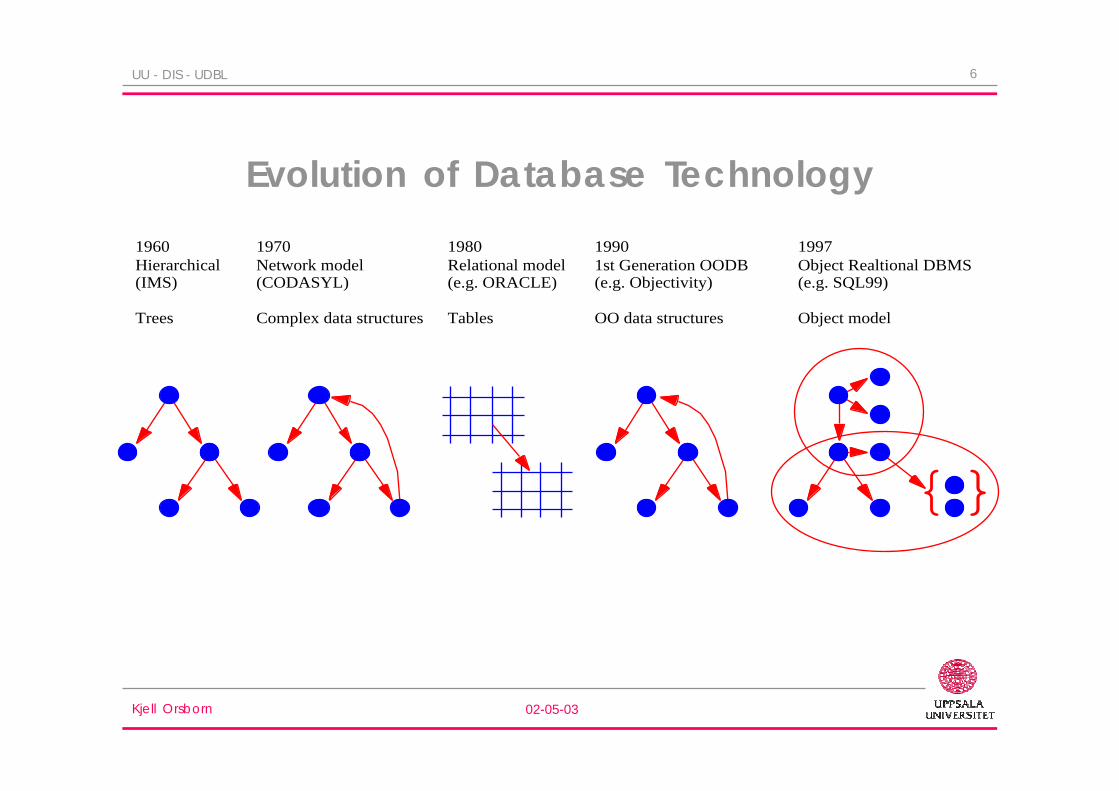
Evolution of Database Technology
{}
1960Hierarchical(IMS)
Trees
1970Network model(CODASYL)
Complex data structures
1980Relational model(e.g. ORACLE)
Tables
19901st Generation OODB(e.g. Objectivity)
OO data structures
1997Object Realtional DBMS(e.g. SQL99)
Object model
Kjell Orsborn 02-05-03
7UU - DIS - UDBL
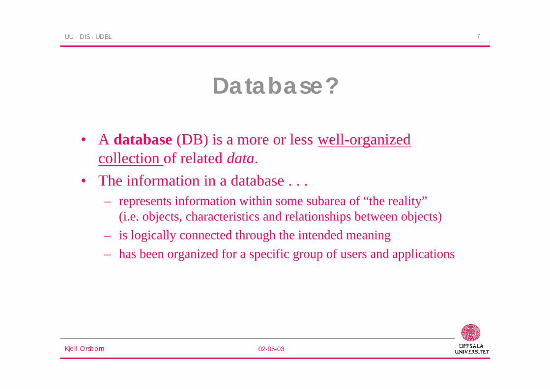
Database?
• A database (DB) is a more or less well-organizedcollection of related data.
• The information in a database . . .– represents information within some subarea of “the reality”
(i.e. objects, characteristics and relationships between objects)
– is logically connected through the intended meaning
– has been organized for a specific group of users and applications
Kjell Orsborn 02-05-03
8UU - DIS - UDBL
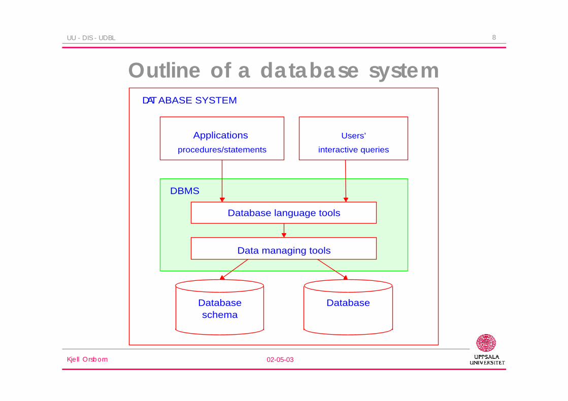
Outline of a database system
Database Databaseschema
DBMS
DATABASE SYSTEM
Users’
interactive queries
Applications
procedures/statements
Data managing tools
Database language tools
Kjell Orsborn 02-05-03
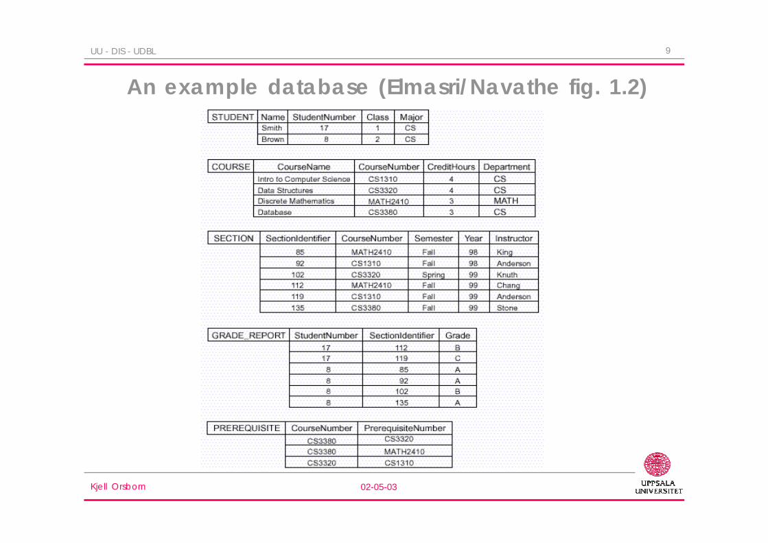
9UU - DIS - UDBL
An example database (Elmasri/Navathe fig. 1.2)

Kjell Orsborn 02-05-03
10UU - DIS - UDBL
Database management system?
• A database management system (DBMS) is one (or several)program that provides functionality for users to develop, use,and maintain a database.
• Thus, a DBMS is a general software system for defining,populating (creating), and manipulating databases for differenttypes of applications.
Kjell Orsborn 02-05-03
11UU - DIS - UDBL
Back to the example ...
• Defining this DB involve– declaration of files, records, fields and data types for each fields.
• Population of the DB means– that the files are filled with data about individual students, courses
etc.
• Manipulation is then carried out by users directly via aquery language or indirectly via application programs:– updates
– queries to the DB

Kjell Orsborn 02-05-03
12UU - DIS - UDBL
Database System?• A database system consists of . . .
– the physical database (instance)
– a database management system
– one or several database languages(means for communicating with the database)
– one or several application program(s)
• A database system makes a simple and efficient manipulationof large data sets possible.
• The term DB can refer to both the content and to the system.The answer to this ambiguity is governed by the context.

Kjell Orsborn 02-05-03
13UU - DIS - UDBL
Why DB?• DB in comparison to manual paper-based registers:
– Better compactness– Faster search– Simpler maintenance– “Greater usability”
• DB in comparison to conventional file management:– Data model - data abstraction– Meta-data– Program- and data independence– Multiple views of the same data– High-level language for managing the database– Efficient search/access of large data sets
Database
Kjell Orsborn 02-05-03
14UU - DIS - UDBL
Problems that can be avoided using adatabase system
• Redundancy and inconsistency
• Slow process to find correct information
• Different formats for data storage
• Erroneous or unreasonable values
• Incomplete updates
• Concurrent access
• Unauthorized access

Kjell Orsborn 02-05-03
15UU - DIS - UDBL
Data model?
• Every DB has a data model which makes it possible to“hide” the physical representation of data.
• A data model is a formalism that defines a notation fordescribing data on an abstract level together with a set ofoperations to manipulate data represented using this datamodel.
• Data models are used for data abstraction - making itpossible to define and manipulate data on an abstract level.

Kjell Orsborn 02-05-03
16UU - DIS - UDBL
Data model continued . . .
• E.g. assume that information about employees in anenterprise exists in a file employees which is a sequencerecords of the type:
record
name: char[30];
manager: char[30]
end
An abstract model of this file is a relation:employees(name, manager)
, where employees is the name of the relation and name andmanager is the attribute of the relation.

Kjell Orsborn 02-05-03
17UU - DIS - UDBL
Data models - examples• Examples of data models within the database field are the:
– Hierarchical (IMS),
– Network (IDMS),
– Relational (ORACLE, SYBASE, DB2, InterBase),
– Object-oriented (O2, ObjectStore) and
– Object-relational ( Informix, UniSQL, Iris/AMOS) data model.
• Conceptual data model– ER-model (Entity-Relationship model)
(not an implementation model since there are no operations defined forthe notation)

Kjell Orsborn 02-05-03
18UU - DIS - UDBL
Meta-data, i.e. “data about data”
• Information about which information that exists
• Information about how/where data is stored– file structures
– records
– data types / formats
– name of files, data types
• Information regarding mapping between different schemas
• Meta-data is stored in the, so called, system catalog or datadictionary.

Kjell Orsborn 02-05-03
19UU - DIS - UDBL
Meta-data cont. ...• Meta-data is used by the DBMS to answer questions such as:
(Users)
– Which information exists in the database?
– Is the information “x” in the database?
– What is the cost to access a specific piece of information.
(Database administrator or DBMS)
– How much is different parts of the database used?
– How long is the response time for different types of queries?
– Has any user tried to break the security system of the database?
– Is optimization required of the physical organization of the database withregards to memory utilization or response times?

Kjell Orsborn 02-05-03
20UU - DIS - UDBL
Schema and instance
To be able to separate data in the database and itsdescription the terms database instance and databaseschema are used.
• The schema is created when a database is defined. Adatabase schema is not changed frequently.
• The data in the database constitute an instance. Everychange of data creates a new instance of the database.

Kjell Orsborn 02-05-03
21UU - DIS - UDBL
Data independence
• Reduces the connection between:– the actual organization of data and
– how the users/application programs process data (or “sees” data.)
• Why?– Data should be able to change without requiring a corresponding
alteration of the application programs.
– Different applications/users need different “views” of the samedata.
Kjell Orsborn 02-05-03
22UU - DIS - UDBL
Data dependenciesConventional systems have, in general, a very low level of data
independence:• Even a small change of the data structure, e.g. the introduction or
reduction of a field in a record structure, usually require that one hasto make changes in several programs or routines.
Programs can be dependent of that:• data is located on a specific storage medium
• data has a specific storage format (binary, compressed)
• fields have been coded according to certain rules (Man = 1, Woman =2)
• the file records are sorted in a specific manneretc . . .

Kjell Orsborn 02-05-03
23UU - DIS - UDBL
Data independence - how? By introducing a multi-level architecture where each level
represents one abstraction level.
Three-schema architecture:– In 1978 the following “standard” architecture (ANSI/SPARC
architecture ) for databases was introduced.
It consists of 3 levels:
1. Internal level
2. Conceptual level
3. External level– Each level introduces one abstraction layer and has a schema that
describes how representations should be mapped to the next lowerabstraction level.
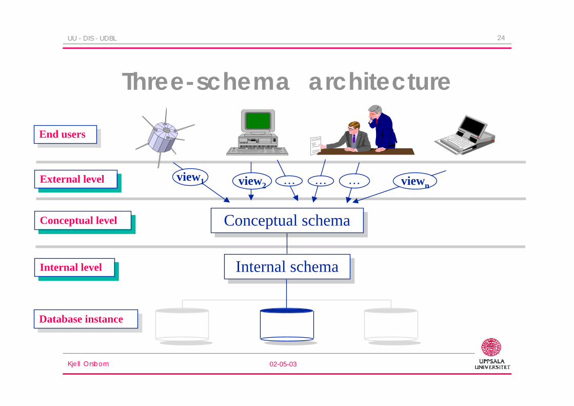
Kjell Orsborn 02-05-03
24UU - DIS - UDBL
Three-schema architecture
Internal schemaInternal schema
Conceptual schemaConceptual schema
Database instanceDatabase instance
Internal levelInternal level
Conceptual levelConceptual level
External levelExternal level
End usersEnd users
view1 view2 viewn

Kjell Orsborn 02-05-03
25UU - DIS - UDBL
Internal schema
• Describes storage structures and access paths for thephysical database.– Abstraction level: files, index files etc.
• Is usually defined through the data definition language(DDL) of the DBMS.
Kjell Orsborn 02-05-03
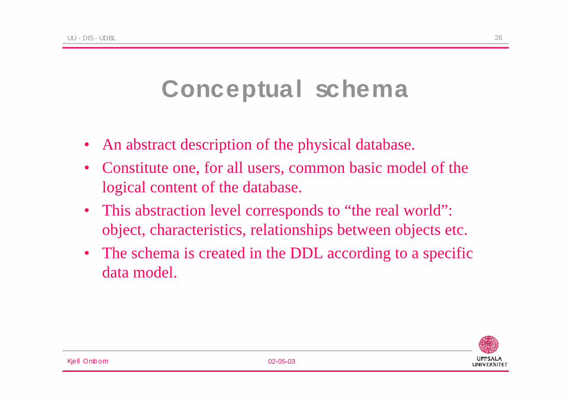
26UU - DIS - UDBL
Conceptual schema
• An abstract description of the physical database.
• Constitute one, for all users, common basic model of thelogical content of the database.
• This abstraction level corresponds to “the real world”:object, characteristics, relationships between objects etc.
• The schema is created in the DDL according to a specificdata model.
Kjell Orsborn 02-05-03
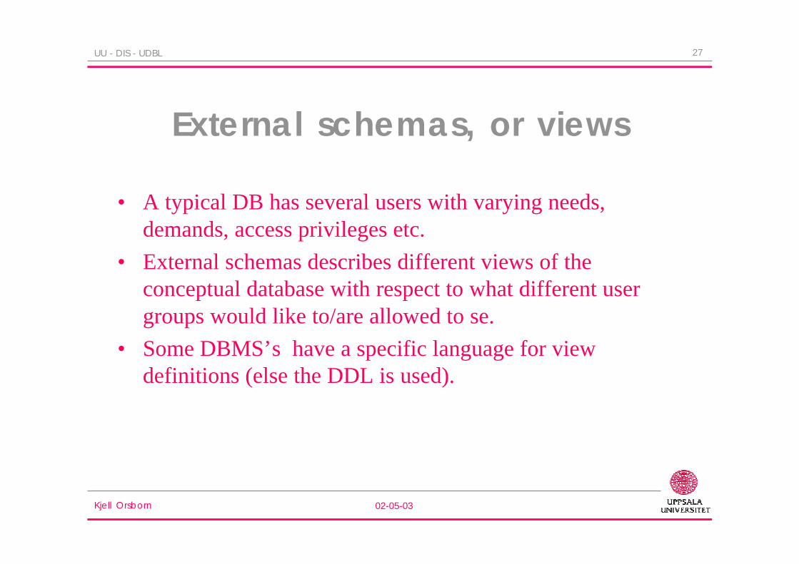
27UU - DIS - UDBL
External schemas, or views
• A typical DB has several users with varying needs,demands, access privileges etc.
• External schemas describes different views of theconceptual database with respect to what different usergroups would like to/are allowed to se.
• Some DBMS’s have a specific language for viewdefinitions (else the DDL is used).
Kjell Orsborn 02-05-03
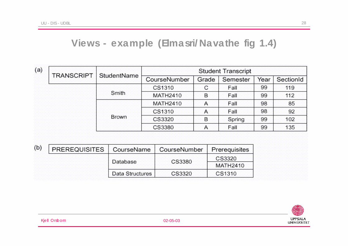
28UU - DIS - UDBL
Views - example (Elmasri/Navathe fig 1.4)

Kjell Orsborn 02-05-03
29UU - DIS - UDBL
Views - example in SQL
• Assume that we have a relation (table) consistinginformation about employees in an enterprise:
employees(name,dept,salary,address)
• and wish to give a user group rights “to see” allinformation in the table except the SALARY field.
• This can be accomplished by the definition of a view calledsafe-emp:
create view safe-emps by
select name, dept, address
from employees;

Kjell Orsborn 02-05-03
30UU - DIS - UDBL
Data independence in the three-schema architecture
1. Logical data independence– The possibility to change the conceptual schema without
influencing the external schemas (views).• e.g. add another field to a conceptual schema.
2. Physical data independence– The possibility to change the internal schema without influencing
the conceptual schema..• the effects of a physical reorganization of the database, such as adding
an access path, is eliminated.

Kjell Orsborn 02-05-03
31UU - DIS - UDBL
Database languages
• The term database language is a generic term for a class oflanguages used for defining, communicating with ormanipulating a database.
• In conventional programming languages, declarations andprogram sentences is implemented in one and the samelanguage.
• A DB system uses several different languages.– Storage Definition Language (SDL)
– Data Definition Language (DDL)
– View Definition Language (VDL)
– Data Manipulation Language (DML)

Kjell Orsborn 02-05-03
32UU - DIS - UDBL
DDL and DML
• DDL is used by the database administrator and others todefine internal and conceptual schema.
• In this manner the database is designed. Subsequentmodifications in the design is also made in DDL.
• DML is used by DB users and application programs toretrieve, add, remove, or alter the information in thedatabase. The term query language is usually used assynonym to DML.

Kjell Orsborn 02-05-03
33UU - DIS - UDBL
DDL example in SQLcreate table
flights(number: int,
Date:char(6),
Seats: int,
from:char(3),
to: char(3));
create index for flights on number;
• The first expression defines a relation, its attribute and theirtypes.
• The second expression creates an index as part of the internalschema making search faster for flights, given a flight no. (e.g.this can be accomplished by creating a hash table with numberas the key).

Kjell Orsborn 02-05-03
34UU - DIS - UDBL
DML example in SQL
update flights
set seats = seats -4
where number = 123 and date = ‘AUG 31’
“Decrease the no. of seats in flight no.. 123 on August 31 with 4.”
insert into flights
values(171,
‘AUG 21’, 100, ‘ROM’, ‘JFK’)
“Add a new flight with flight no.. 171 and 100 seats, from Rom to NewYork (JFK) on August 21”

Kjell Orsborn 02-05-03
35UU - DIS - UDBL
Host language
• Application programs that work with a DB are mainly written ina normal programming language: C, COBOL, PASCAL, C++,Java, etc.
• The part of the program that interact with the DB is normallywritten in a DML.
• The DML commands are embedded in the code that is written inthe host language.
##get(b)
sum := sum + b;
##store(sum)
Kjell Orsborn 02-05-03
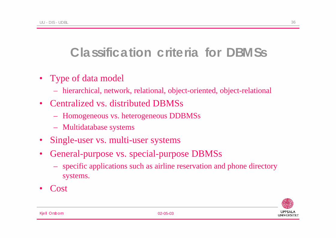
36UU - DIS - UDBL
Classification criteria for DBMSs
• Type of data model– hierarchical, network, relational, object-oriented, object-relational
• Centralized vs. distributed DBMSs– Homogeneous vs. heterogeneous DDBMSs
– Multidatabase systems
• Single-user vs. multi-user systems
• General-purpose vs. special-purpose DBMSs– specific applications such as airline reservation and phone directory
systems.
• Cost
Kjell Orsborn 02-05-03
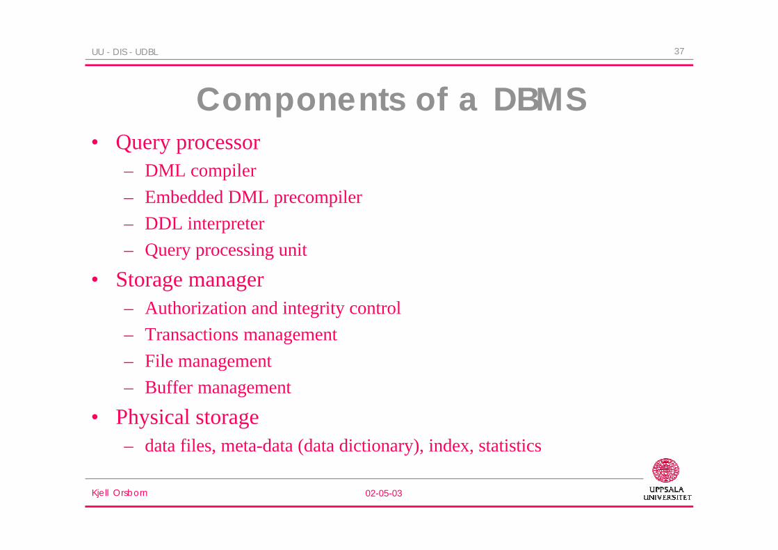
37UU - DIS - UDBL
Components of a DBMS• Query processor
– DML compiler
– Embedded DML precompiler
– DDL interpreter
– Query processing unit
• Storage manager– Authorization and integrity control
– Transactions management
– File management
– Buffer management
• Physical storage– data files, meta-data (data dictionary), index, statistics
Kjell Orsborn 02-05-03
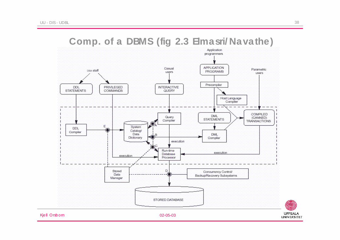
38UU - DIS - UDBL
Comp. of a DBMS (fig 2.3 Elmasri/Navathe)
Kjell Orsborn 02-05-03
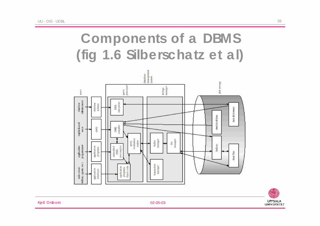
39UU - DIS - UDBL
Components of a DBMS(fig 1.6 Silberschatz et al)

Kjell Orsborn 02-05-03
40UU - DIS - UDBL
Introduction to Database Design UsingEntity-Relationship Modeling
Elmasri/Navathe chs 3-4
Lecture 1Kjell Orsborn
Department of Information Science
Uppsala University, Uppsala, Sweden
Kjell Orsborn 02-05-03
41UU - DIS - UDBL
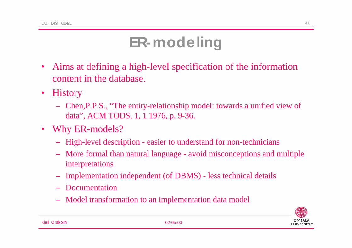
ER-modeling• Aims at defining a high-level specification of the information
content in the database.
• History– Chen,P.P.S., “The entity-relationship model: towards a unified view of
data”, ACM TODS, 1, 1 1976, p. 9-36.
• Why ER-models?– High-level description - easier to understand for non-technicians
– More formal than natural language - avoid misconceptions and multipleinterpretations
– Implementation independent (of DBMS) - less technical details
– Documentation
– Model transformation to an implementation data model

Kjell Orsborn 02-05-03
42UU - DIS - UDBL
ER-modeling cont. ...
• How to do?– Identify:
• Entity types and attributes
• Relationship types
– Normally presented in a graphical ER-diagram
– An ER-model can later be transformed to an implementation data model,such as the relational data model

Kjell Orsborn 02-05-03
43UU - DIS - UDBL
Example of an ER-diagram

Kjell Orsborn 02-05-03
44UU - DIS - UDBL
Terminology in ER-modeling• Entity type - Entity
– Physical or abstract concepts with some sort of identity..
• Attribute– Characteristics or different aspects that describes an entity.
• Relationship type - Relationship– Represents relationships between entities
ER-diagram

Kjell Orsborn 02-05-03
45UU - DIS - UDBL
Entity type
• An entity type represents a set of entities that have thesame set of attributes.– Entity types express the intention, i.e. the meaning of the concept
whereas the set of entities represents the extension of that type.
– Names of entity types are given in singular form.
– The description of an entity type is called its schema.PERSONname, ssn, address, phoneno
– Each attribute in an entity type is associated with a domain thatindicates the allowed values of that attribute.
Kjell Orsborn 02-05-03
46UU - DIS - UDBL
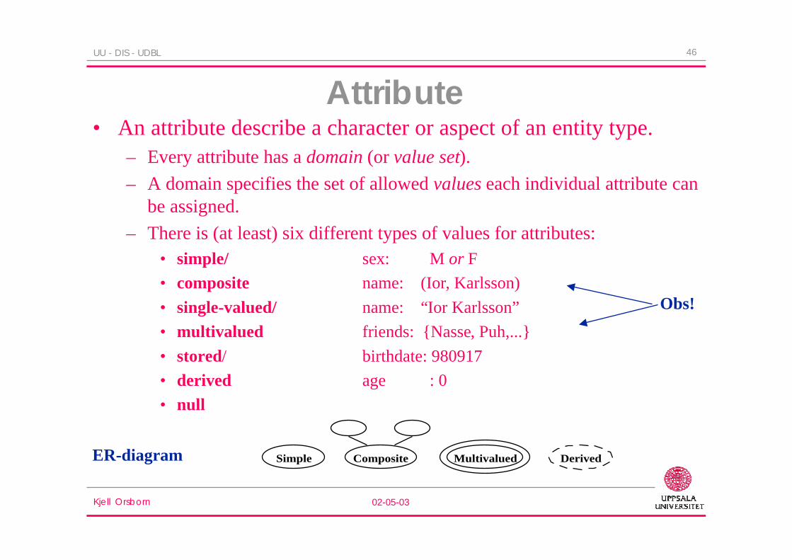
Attribute• An attribute describe a character or aspect of an entity type.
– Every attribute has a domain (or value set).
– A domain specifies the set of allowed values each individual attribute canbe assigned.
– There is (at least) six different types of values for attributes:• simple/ sex: M or F
• composite name: (Ior, Karlsson)
• single-valued/ name: “Ior Karlsson”
• multivalued friends: {Nasse, Puh,...}
• stored/ birthdate: 980917
• derived age : 0
• null
Obs!
ER-diagram Simple Composite Multivalued Derived

Kjell Orsborn 02-05-03
47UU - DIS - UDBL
Key
• An attribute that has unique values for every instance of anentity type is called a key attribute.
• Sometimes several attributes are used together to get a uniquekey.
• An entity type can have more than one key.
key hello
Kjell Orsborn 02-05-03
48UU - DIS - UDBL
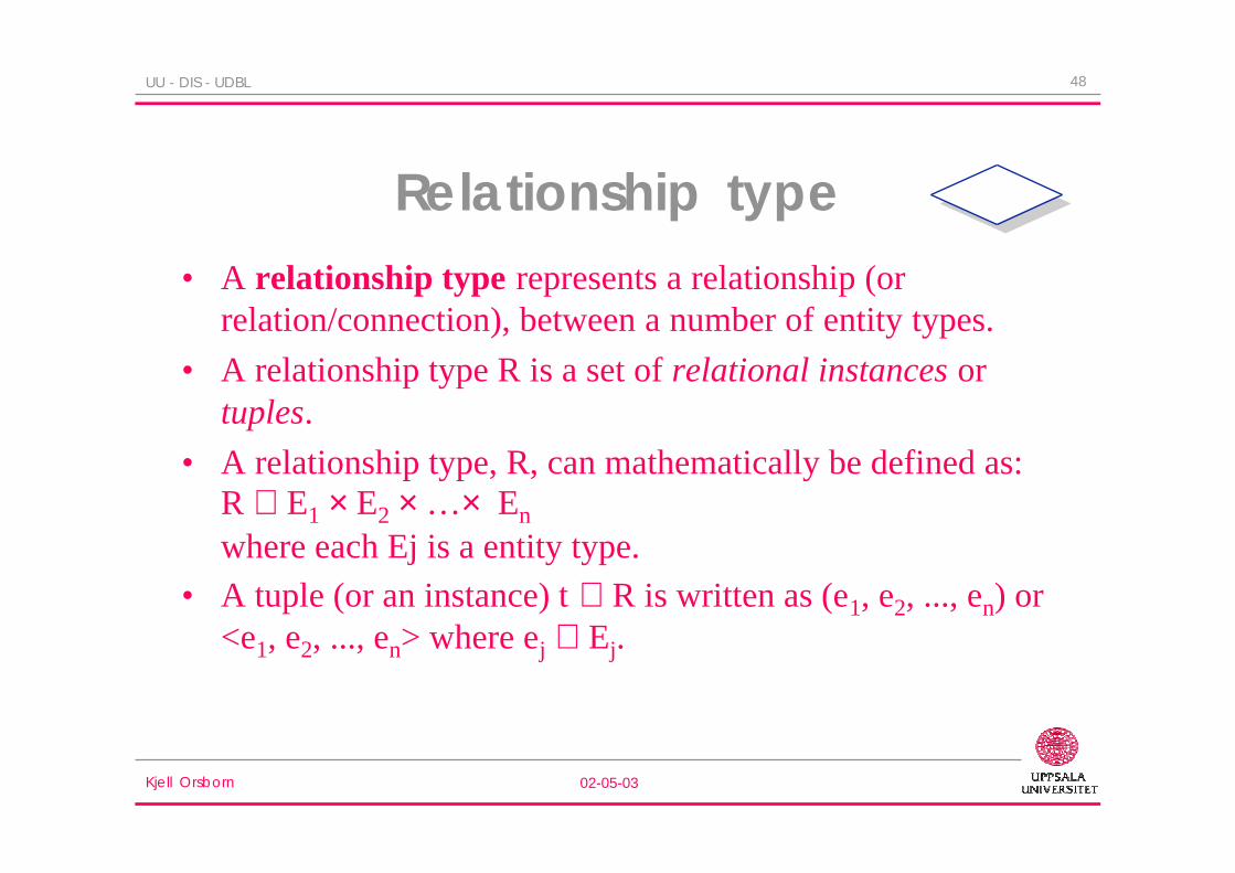
Relationship type• A relationship type represents a relationship (or
relation/connection), between a number of entity types.
• A relationship type R is a set of relational instances ortuples.
• A relationship type, R, can mathematically be defined as:R ⊆ E1 × E2 × …× En
where each Ej is a entity type.
• A tuple (or an instance) t ∈ R is written as (e1, e2, ..., en) or<e1, e2, ..., en> where ej ∈ Ej.

Kjell Orsborn 02-05-03
49UU - DIS - UDBL
Structural constraints forrelationship types
• Cardinality ratio constraint specifies the number ofrelational instances that an entity can take part in.For binary relationship types:
– one-to-one (1:1)
– one-to-many (1:N)
– many-to-many (M:N)
1 1
N
NM
1
Kjell Orsborn 02-05-03
50UU - DIS - UDBL
Structural constraints cont. ...
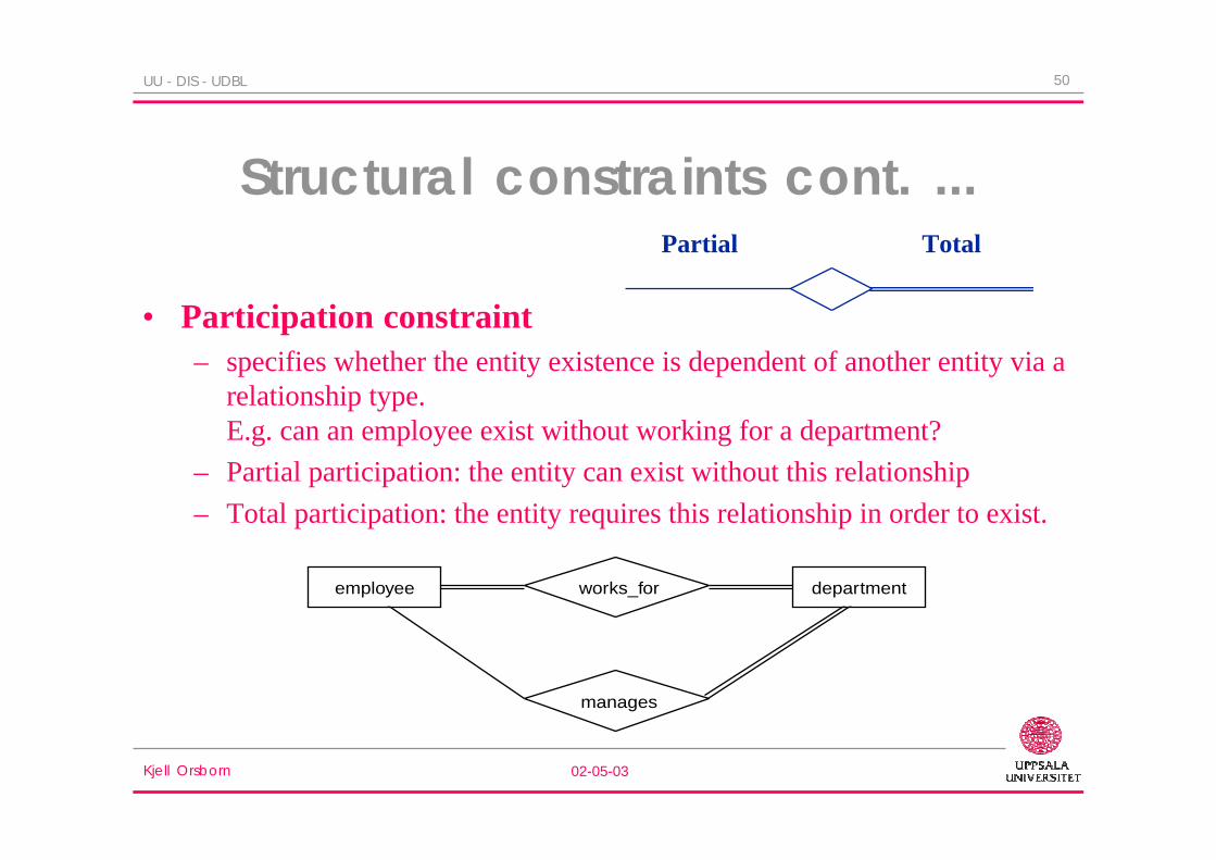
• Participation constraint– specifies whether the entity existence is dependent of another entity via a
relationship type.E.g. can an employee exist without working for a department?
– Partial participation: the entity can exist without this relationship
– Total participation: the entity requires this relationship in order to exist.
Partial Total
works_foremployee department
manages

Kjell Orsborn 02-05-03
51UU - DIS - UDBL
Roles of relationship types
• A role name specifies what role an entity type plays in a specificrelationship
• Role names are sometimes used in ER-diagrams to clarify theroles of the participating entity types.
SupervisionSupervision
EmployeeEmployee
workerN1manager
Kjell Orsborn 02-05-03
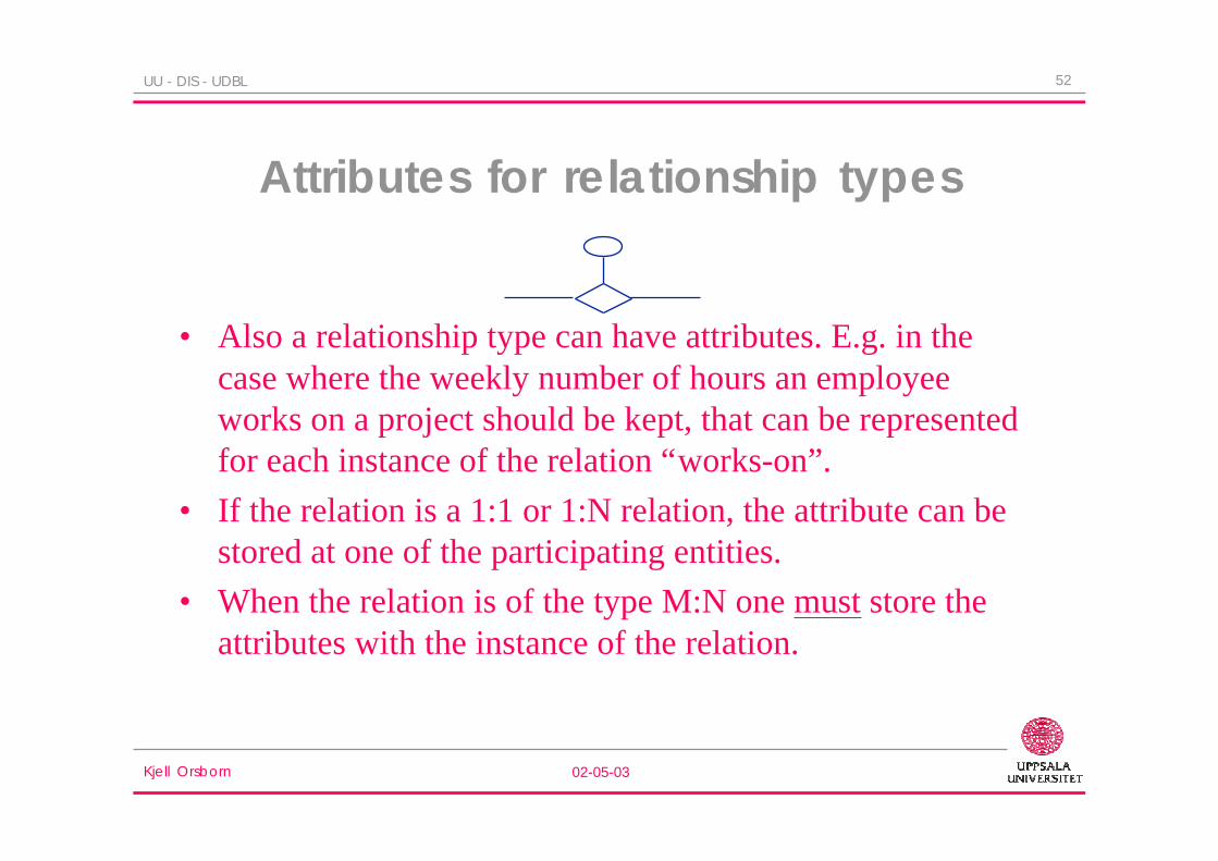
52UU - DIS - UDBL
Attributes for relationship types
• Also a relationship type can have attributes. E.g. in thecase where the weekly number of hours an employeeworks on a project should be kept, that can be representedfor each instance of the relation “works-on”.
• If the relation is a 1:1 or 1:N relation, the attribute can bestored at one of the participating entities.
• When the relation is of the type M:N one must store theattributes with the instance of the relation.

Kjell Orsborn 02-05-03
53UU - DIS - UDBL
Weak entity types• Weak entity types are those that are meaningless without an
owner entity type.
• Weak entities are uniquely identified in the extension with theirowner’s key attributes together with its own (broken) underlinedattribute.
• The relationship to the owner is called the identifyingrelationship.
Kjell Orsborn 02-05-03
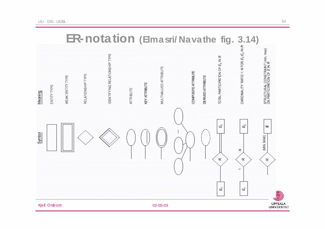
54UU - DIS - UDBL
ER-notation (Elmasri/Navathe fig. 3.14)

Kjell Orsborn 02-05-03
55UU - DIS - UDBL
Another ER diagram

Kjell Orsborn 02-05-03
56UU - DIS - UDBL
ER model transformations
• Replacing multi-valued attributes by an entity type
DEPARTMENTDEPARTMENT
N1
Dept idDept idNameName
Location
Dept idDept idNameName
LOCATIONLOCATION
LocationLocation
located atlocated atDEPARTMENTDEPARTMENT
Kjell Orsborn 02-05-03
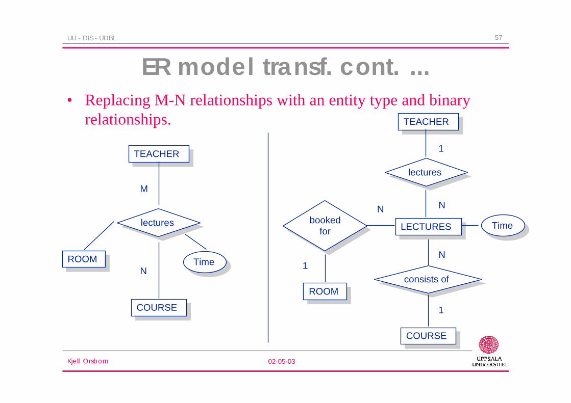
57UU - DIS - UDBL
ER model transf. cont. ...• Replacing M-N relationships with an entity type and binary
relationships.
N
M
TimeTime
COURSECOURSE
lectureslectures
TEACHERTEACHER
ROOMROOM N
N
TimeTime
COURSECOURSE
LECTURESLECTURES
TEACHERTEACHER
ROOMROOMconsists ofconsists of
1
lectureslectures
1
bookedfor
bookedfor
N
1
Kjell Orsborn 02-05-03
58UU - DIS - UDBL
Example ER-modeling
– An enterprise consists of a number of departments. Each department hasa name, a number, a manager, and a number of employees. The startingdate for every department manager should also be registered. Adepartment can have several office rooms.
– Every department finances a number of projects. Each project has aname, a number and an office room.
– For each employee, the following information is kept: name, socialsecurity number, address, salary and sex. An employee works for onlyone department but can work with several projects that can be related todifferent departments. Information about the number of hours (per week)that an employee work with a project should be stored. Information aboutthe employees manager should also be stored.

Kjell Orsborn 02-05-03
59UU - DIS - UDBL
Entity types in the example
EMPLOYEEname(fname,fname), ssn, address,sex, salary, department, manager,{works-on(project, hours)}
DEPARTMENTname, number, {room}, dmanager, startdate
PROJECTname, number , room , department
Kjell Orsborn 02-05-03
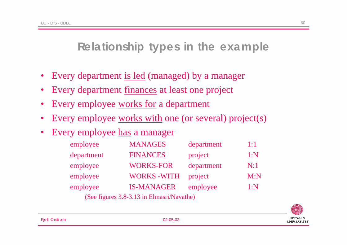
60UU - DIS - UDBL
Relationship types in the example
• Every department is led (managed) by a manager
• Every department finances at least one project
• Every employee works for a department
• Every employee works with one (or several) project(s)
• Every employee has a manageremployee MANAGES department 1:1
department FINANCES project 1:N
employee WORKS-FOR department N:1
employee WORKS -WITH project M:N
employee IS-MANAGER employee 1:N(See figures 3.8-3.13 in Elmasri/Navathe)

Kjell Orsborn 02-05-03
61UU - DIS - UDBL
ER-diagram for the example
M
ANSTÄLLD
kön
adress
lön
personnr
JOBBAR-ÅT
JOBBAR-MED
ÄR-CHEF
startdatum
namn
e-namn f-namn
lokal
nummer
lokal
AVDELNING
PROJEKT
namn
namn
nummer
LEDER
FINANSIERAR
timmar
1 N
N
N
1
N 1
11

Kjell Orsborn 02-05-03
62UU - DIS - UDBL
Extended Entity-Relationship(EER) modeling
• The intention of using an E-R diagram is to use it as a basisfor user communication or for getting to a good designspecification.– i.e. try to make it simple and avoid to much complexity.
• EER (extended or enhanced ER) introduces severalnotational extensions to deal concepts such as:– Superclass /subclass (supertype/subtype, is-a relationship)
• specialization/generalization
• constraints
– Aggregation (whole/part or part-of relationship)
– Union types (category)

Kjell Orsborn 02-05-03
63UU - DIS - UDBL
EER diagram notation for specialization and subclass

Kjell Orsborn 02-05-03
64UU - DIS - UDBL
Subclasses, superclasses & inheritance
• Two generic ideas for creating superclass/subclass relationships– Specialization of superclass into subclasses
– Generalization of subclasses into a superclass
• Constraints and characteristics of spec. & gen.– Constraints
• Predicate-defined (condition-defined) sub-classes
• Attribute-defined
• User-defined
– Disjointness• Disjoint
• Overlapping
– Completeness• Total
• Partial

Kjell Orsborn 02-05-03
65UU - DIS - UDBL
Generalization of subclasses

Kjell Orsborn 02-05-03
66UU - DIS - UDBL
Overlapping (nondisjoint) subclasses
Kjell Orsborn 02-05-03
67UU - DIS - UDBL
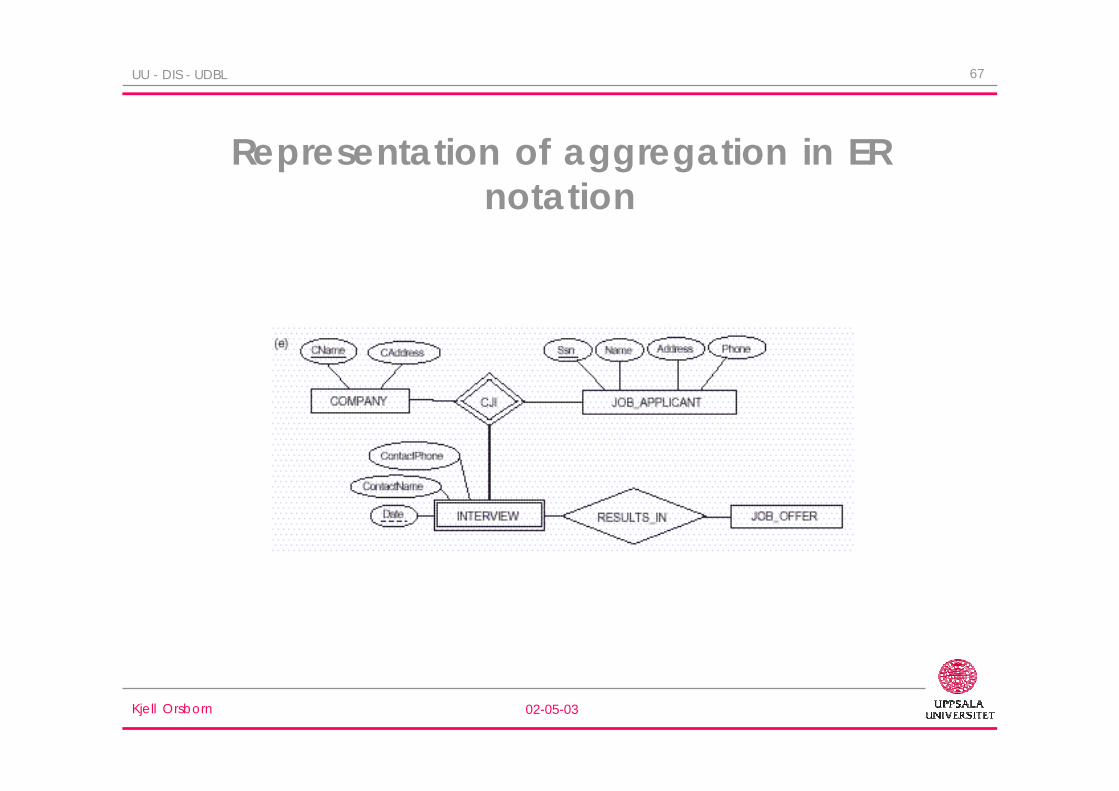
Representation of aggregation in ERnotation

Kjell Orsborn 02-05-03
68UU - DIS - UDBL
A UML conceptual schema

Kjell Orsborn 02-05-03
69UU - DIS - UDBL
Specialization/generalization in UML
Kjell Orsborn 02-05-03
70UU - DIS - UDBL
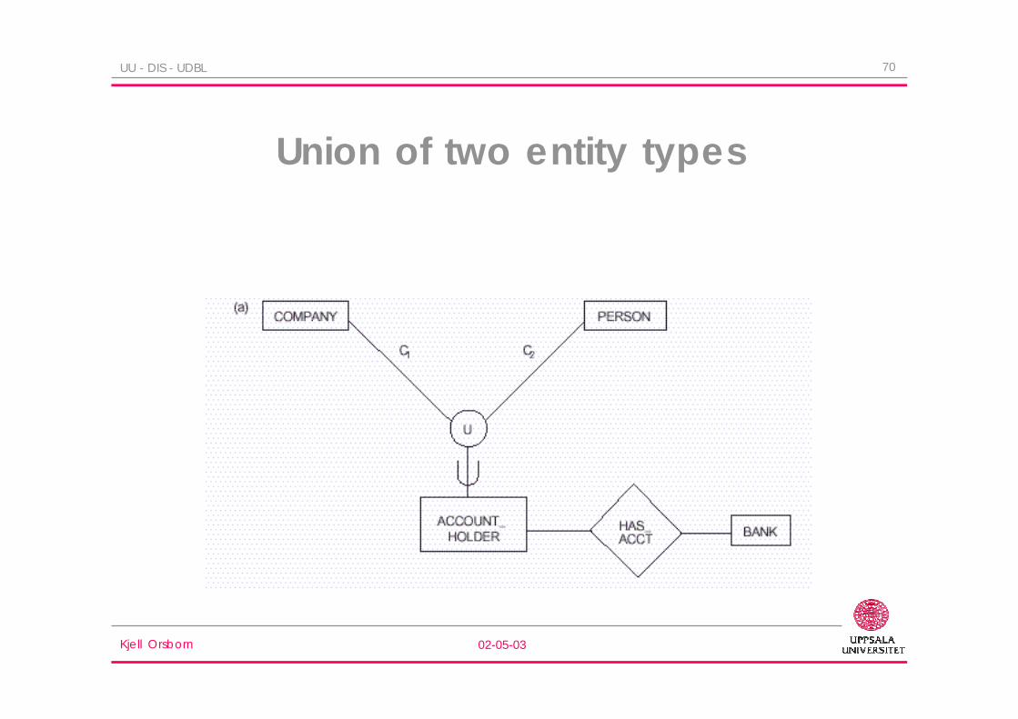
Union of two entity types

Kjell Orsborn 02-05-03
71UU - DIS - UDBL
Alternativediagrammatic
notation forER/EER


