
ORDERING INFORMATIONPART NO DESCRIPTIONLDTC 2/2E Enclosed 2.2 A LD/TEC ControllerLDTC 2/2O Open Frame 2.2 A LD/TEC Controller
WEV-300* Thermal Washer & HeatsinkWEV-301* Thermal Washer, Heatsink, 5 V FanWEV-302* Thermal Washer, Heatsink, 12 V Fan
POWER & STABILITYCombine the drive power of the WLD3343 laser driver (up to 2.2 A) with the temperature stability of the WTC3243 temperature controller (±2.2 A available) on one small board. Available as an open frame or in a chassis mount enclosure.
APPLICATIONSIdeal for integrated laser driver or LED packages that include temperature control, often utilized in medical diagnostic equipment, remote sensing, analytical instrumentation, military, and communications applications.
POWER YOUR APPLICATION WITH THE RIGHT FEATURESThe WTC3243 will control temperature using thermistors, RTDs, or linear temperature sensors such as the LM335 or the AD590. Adjust temperature using the onboard trimpot or a remote voltage input from a panel mount potentiometer, DAC, or other voltage source. A default temperature setpoint configuration provides fault tolerance and avoids accidental damage to system components. Adjustable trimpots configure heat and cool current limits.
The WLD3343 Laser Driver maintains precision laser diode curent (Constant Current Mode) or stable photodiode current (Constant Power mode) using electronics compatible with A/B Type lasers.
FEATURES AND BENEFITS• ±2.2 A of TEC and 2.2 A of LD current (up to 3 A
with product variation)• Small package size• Single supply operation LD: +5 to +12 V• Single supply operation TC: +5 to +28 V• Slow start laser diode protection• Constant Current or Constant Power modes• Adjustable laser diode current limit• Remote TTL Shutdown/Interlock• Ultra-stable PI control loop• Separate heat & cool current limits• Failsafe Setpoint default for D/A remote
temperature setting
PAGE
e
Applies to Product Revisions A – B© January 2019
A
Laser Type
BLaser Type
LM335AD590RTDRT
Pb
RoHS Com
plia
nt
CONTENTSQUICK CONNECT GUIDE 2PIN DESCRIPTIONS 5ELECTRICAL SPECIFICATIONS 7SAFETY INFORMATION & THERMAL DESIGN CONSIDERATIONS 9OPERATING INSTRUCTIONS –
TEMPERATURE CONTROLLER 10LASER DRIVER 12
ADDITIONAL TECHNICAL INFORMATION 15TROUBLESHOOTING –
TEMPERATURE CONTROLLER 20LASER DRIVER 21
MECHANICAL SPECIFICATIONS 23CERTIFICATION AND WARRANTY 26
* Only for 2/2O
406-587-4910www.teamWavelength.com
LDTC2/2E & LDTC2/2OLaser Diode & Temperature Controllers
DATASHEET AND OPERATING GUIDE
© 2018 www.teamWavelength.com 2
LDTC2/2 LASER DIODE DRIVER AND TEMPERATURE CONTROLLER
Tset LIMA LIMB ILIM ISET
J1 J2
J3COMmonSENsor-SENsor+TEC-TEC+COMmonLDAnodePDCathodePDAnodeLDCathode
GNDVS (5-28 V)VDD (5-12 V)
COMmonR TC SETpointSET T MONitorACT T MONitor
LD I MONitorLD P MONitor
COMmonR LDSETpoint
COMmonLD SHD
PD MONitorCOMmon
321
10987654321
121110987654321
LD ENABLETOGGLESWITCH
EXTERNALVOLTMETER
OR
VS
BandgapVoltageReferenceD/A
0 V = OPEN = ENABLE>3 V = CLOSED = DISABLE
AD590
THERMISTOR,RTD, or ICs
OR
10 kΩ
OR
V
EXTERNALVOLTMETER
Like R TC SET (Pin 11)
VSVDD
LD ENABLE
VDD and VS can be tied together if common voltage provides sufficient compliance for laser diode and thermoelectric loads.
Separate VS if higher compliance is required.
+ ++++
CC
CPExtTset Vset PDset
POWERON
CONSTANT CURRENT orCONSTANT POWER Mode
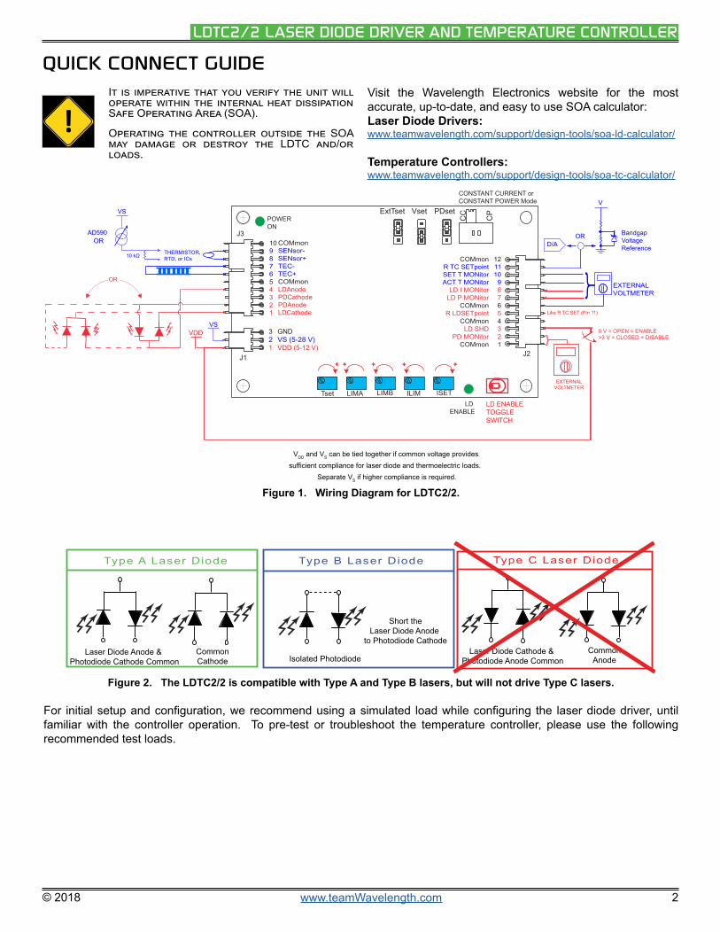
Figure 1. Wiring Diagram for LDTC2/2.
Type A Laser Diode Type B Laser Diode Type C Laser Diode
CommonCathode
Laser Diode Anode & Photodiode Cathode Common Isolated Photodiode
Short theLaser Diode Anode
to Photodiode CathodeCommon
AnodeLaser Diode Cathode &
Photodiode Anode Common
Figure 2. The LDTC2/2 is compatible with Type A and Type B lasers, but will not drive Type C lasers.
For initial setup and configuration, we recommend using a simulated load while configuring the laser diode driver, until familiar with the controller operation. To pre-test or troubleshoot the temperature controller, please use the following recommended test loads.
QUICK CONNECT GUIDE
!It is imperative that you verify the unit will operate within the internal heat dissipation Safe Operating Area (SOA).
Operating the controller outside the SOA may damage or destroy the LDTC and/or loads.
Visit the Wavelength Electronics website for the most accurate, up-to-date, and easy to use SOA calculator:Laser Diode Drivers:www.teamwavelength.com/support/design-tools/soa-ld-calculator/
Temperature Controllers:www.teamwavelength.com/support/design-tools/soa-tc-calculator/

© 2018 www.teamWavelength.com 3
LDTC2/2 LASER DIODE DRIVER AND TEMPERATURE CONTROLLER
RECOMMENDED THERMOELECTRIC TEST LOAD
For the temperature controller, recommended simulated thermoelectric and thermistor circuits are shown in Figure 5 and Figure 6. Configuring the temperature controller using test loads is recommended for setting the thermoelectric controller limits or to check the temperature controller operation.
RLOAD
TEC+(Pin J3-6)
TEC-(Pin J3-7)
RLOAD = 1 Ω, Rated >10 W
TEC Test Load
IMETER
Figure 5. Simulated Thermoelectric Test Load
R1
R1 = 10 kΩ, ¼ W resistor
SEN-(Pin J3-9)
SEN+(Pin J3-8)
Simulated Thermistor
Figure 6. Simulated Thermistor
This circuit simulates a 10 kΩ thermistor operating at 25°C. Use the 100 µA bias current setting to create a 1 V sensor signal. Other resistor values can be used depending on the sensor voltage you wish to simulate. To drive cooling current, set T SET to 1.35 V and to drive heating current, set T SET to 0.85 V.
NOTE: To stay within the Safe Operating Area while using the test load, VS must not exceed 5 V.
RECOMMENDED LASER DRIVER TEST LOAD
For the laser diode driver, recommended simulated laser loads are shown in Figure 3 and Figure 4.
1N4001
1N4001
LDC(Pin J3-1)
LDA(Pin J3-4)
1 Ω, 2 W
Constant Current Mode
Figure 3. Constant Current Mode Test Load
In Constant Power Mode, the setpoint correlates to the photodiode feedback current, which represents a fraction of the light power emitted by the laser diode. Photodiode current is measured by monitoring LD P MON.
24 Ω
1N4001
1N40012N3906
0.33 µF
PDA(Pin J3-2)
LDA(Pin J3-4)
LDC(Pin J3-1)
Constant Power Mode
The 24 Ω resistor typically produces approximately 30 mA laser driver current. Vary the resistor value to change the output current.
1 Ω, 2 W
Figure 4. Constant Power Mode Test Load
NOTE: To determine the actual drive current, measure the voltage drop across the 1 Ω resistor. Do not insert an ammeter in series with the output circuit; doing so may cause instability in the control loop. To stay within the Safe Operating Area while using the test load, VS must not exceed 5 V.

© 2018 www.teamWavelength.com 4
LDTC2/2 LASER DIODE DRIVER AND TEMPERATURE CONTROLLER
PIN DESCRIPTIONSTable 1. Pin Descriptions and Wire Colors
PIN NAME CABLE COLOR PIN DESCRIPTION
Connector J1 – WCB300
1 (VDD)Supply Voltage to Control Electronics and Laser Diode
RedConnect +5 to +12 V between Pins 1 & 3 to power the control electronics and the output drive to the laser diode. Reference the Safe Operating Area Calculator.
2 (VS) Supply Voltage to Output TEC Drive White Connect +5 to +28 V between Pins 2 & 3 to drive the TEC output stage.
Reference the Safe Operating Area Calculator.3 (GND) Power Supply Ground Black Connect power supply ground to this pin.Connector J2 – WCB309
1 (COM) Common Tan Low current GND for monitors, DACs, External VSET, etc.PIN 1 not available on Rev. A
2 (PD MON) PD Monitor in CC mode Pink Photodiode Monitor in Constant Current mode.PIN 2 not available on Rev. A
3 (LD SHD) LD Shutdown/Interlock (TTL-Compatible) Grey Float or GND = Enable Laser Diode Current
Input > 3 V = Disable Laser Diode Current4 (COM) Common Violet Low current GND for monitors, DACs, External VSET, etc.
5 (R LD SET) Remote Laser Diode Setpoint/Modulation Input Yellow Voltage Input range is 0 to 2 V. Transfer function is given in Table 2.
6 (COM) Common Orange Low current GND for monitors, DACs, External VSET, etc.
7 (LD P MON) Photodiode Monitor BlueMonitor the laser diode power. This pin produces a voltage proportional to the current produced by the laser diode monitor photodiode. See Table 2 for the transfer function.
8 (LD I MON) LD Current Monitor BrownMonitor the laser diode forward current. This pin produces a voltage proportional to the current flowing through the laser diode. See Table 2 for the transfer function
9 (ACT T MON) Actual Temperature Monitor Green
Monitor the actual voltage produced by the temperature sensor. The voltage produced and transfer function to temperature is determined by the sensor chosen.
10 (SET T MON) Setpoint Monitor Red Monitor the temperature setpoint voltage. The voltage produced and transfer function to temperature is determined by the sensor chosen.
11 (R TC SET) Remote Temperature Setpoint White
Connect a voltage source between Pin 11 and Pin 12 to control the temperature setting remotely. A default value of 1 V (approximately 25°C with a 10 kΩ thermistor) will be seen by the WTC if the voltage at this pin drops below 0.3 V.
12 (COM) Common Black Low current GND for monitors, DACs, External VSET, etc.Connector J3 – WCB3011 (LDC) Laser Diode Cathode Black Laser diode cathode connection.2 (PDA) Photodiode Anode White Photodiode anode connection.3 (PDC) Photodiode Cathode Blue Photodiode cathode connection.4 (LDA) Laser Diode Anode Red Laser diode anode connection.5 (COM) Common Green Low current GND for monitors, DACs, External VSET, etc.6 (TEC+) TEC+ Connection Red/Black Cooling current flows from this pin when using an NTC sensor.7 (TEC-) TEC- Connection Orange Heating current flows from this pin when using an NTC sensor.
8 (SEN+) [1] Temperature Sensor+ White/Black Positive side of temperature sensor. Bias current is driven from SEN+ to SEN-.
9 (SEN-) [1] Temperature Sensor- Orange/Black Ground connection for the temperature sensor. Refer to Specifications table for input voltage range and damage thresholds.
10 (COM) Common Green/Black Low current GND for monitors, DACs, External VSET, etc.
[1] See page 14 for additional information regarding the use of RTDs, AD590, and LM335 sensors with the LDTC2/2.
© 2018 www.teamWavelength.com 5
LDTC2/2 LASER DIODE DRIVER AND TEMPERATURE CONTROLLER
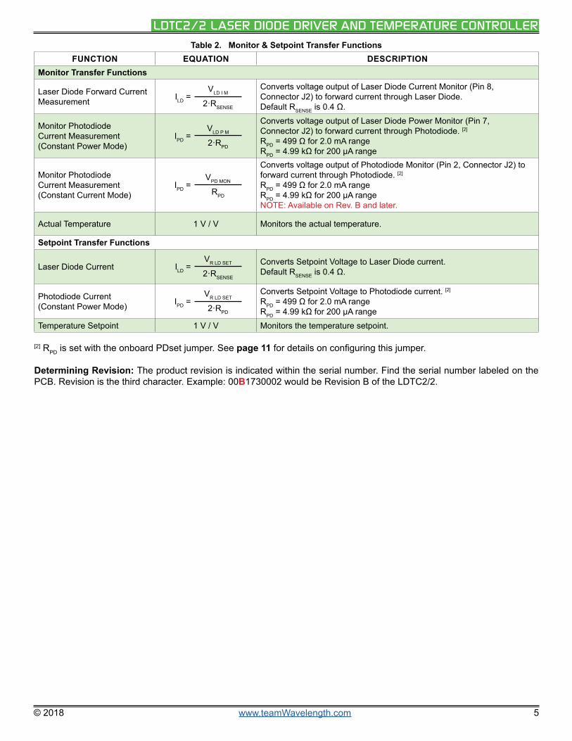
Table 2. Monitor & Setpoint Transfer FunctionsFUNCTION EQUATION DESCRIPTION
Monitor Transfer Functions
Laser Diode Forward Current Measurement ILD =
VLD I M
2·RSENSE
Converts voltage output of Laser Diode Current Monitor (Pin 8, Connector J2) to forward current through Laser Diode. Default RSENSE is 0.4 Ω.
Monitor Photodiode Current Measurement (Constant Power Mode)
IPD =VLD P M
2·RPD
Converts voltage output of Laser Diode Power Monitor (Pin 7, Connector J2) to forward current through Photodiode. [2] RPD = 499 Ω for 2.0 mA rangeRPD = 4.99 kΩ for 200 μA range
Monitor Photodiode Current Measurement (Constant Current Mode)
IPD =VPD MON
RPD
Converts voltage output of Photodiode Monitor (Pin 2, Connector J2) to forward current through Photodiode. [2] RPD = 499 Ω for 2.0 mA rangeRPD = 4.99 kΩ for 200 μA rangeNOTE: Available on Rev. B and later.
Actual Temperature 1 V / V Monitors the actual temperature.
Setpoint Transfer Functions
Laser Diode Current ILD =VR LD SET
2·RSENSE
Converts Setpoint Voltage to Laser Diode current.Default RSENSE is 0.4 Ω.
Photodiode Current (Constant Power Mode) IPD =
VR LD SET
2·RPD
Converts Setpoint Voltage to Photodiode current. [2] RPD = 499 Ω for 2.0 mA rangeRPD = 4.99 kΩ for 200 μA range
Temperature Setpoint 1 V / V Monitors the temperature setpoint.
[2] RPD is set with the onboard PDset jumper. See page 11 for details on configuring this jumper.
Determining Revision: The product revision is indicated within the serial number. Find the serial number labeled on the PCB. Revision is the third character. Example: 00B1730002 would be Revision B of the LDTC2/2.

© 2018 www.teamWavelength.com 6
LDTC2/2 LASER DIODE DRIVER AND TEMPERATURE CONTROLLER
ELECTRICAL SPECIFICATIONS
ABSOLUTE MAXIMUM RATINGS SYMBOL LDTC2/2E LDTC2/2O UNIT NOTELD Supply Voltage & Control Electronics VDD +4.75 to +12 VDC
TC Load Supply Voltage VS +4.5 to +28 VDC
Max LD Output Current ILD 2.2 A
Max TC Output Current IOUT ±2.2 A
Laser Driver Internal Power Dissipation PMAX 9 W TAMBIENT = 25ºC
Temperature Controller Internal Power Dissipation PMAX 9 W TAMBIENT = 25ºC (with fan
and heat sink)
Case Operating Temperature [1] TOPR -40 to 85 ºC
Case Storage Temperature TSTG -65 to 150 ºC
Weight 6.5 2.4 oz 184.3 g (LDTC2/2E)68.0 g (LDTC2/2O)
Size 4.8 × 2.7 × 1.14 4.2 × 2.5 × 1 inches 121.9 × 68.6 × 29.0 mm (2/2E) 106.7 × 63.5 × 25.4 mm (2/2O)
LASER DRIVER SPECIFICATIONS MIN TYP MAX UNIT NOTE
CONSTANT CURRENT CONTROLShort Term Stability, 1 hour 200 ppm TAMBIENT = 25ºC
CONSTANT POWER CONTROLShort Term Stability, 1 hour 0.01 % TAMBIENT = 25ºC
Long Term Stability, 24 hours 0.05 % TAMBIENT = 25ºC
OUTPUTPeak Current, IMAX 1.8 2.0 2.2 A With heat sink and fan.
Compliance Voltage, Laser Diode Load 3.0 V Full Temp. Range, ILD=2.0A, 5V
Rise Time 460 nsec ILD = 2 A
Fall Time 320 nsec ILD = 2 A
Bandwidth, Constant Current 1.6 MHz Sinewave input signal
Bandwidth, Constant Power Depends on Photodiode Bandwidth
Delayed Start 0.25 sec
Slow Start Ramp 0.01 sec
POWER SUPPLYVoltage, VDD 5 12 V
Quiescent Current, VDD 5 10 15 mA
MODULATION INPUTVSET Input Voltage Range 0 2 V
VSET Damage Threshold < -0.5 > 5.4 V
VSET Input Impedance 20 kΩ
[1] With Revision D of the WLD3343, an internal thermostat has been added to activate Shutdown (SHD) when the internal temperature exteeds 105°C. The output will be re-enabled after a 250 to 300 msec slow-start once the internal temperature drops below 95°C.
CAUTION: Operation higher than 5 V on VDD (i.e. 12 V) requires close evaluation of the SOA curves and current limit settings. Damage to the WLD or WTC will occur if they are operated outside their Safe Operating Area. Contact the factory if you plan to use higher than 5 V.

© 2018 www.teamWavelength.com 7
LDTC2/2 LASER DIODE DRIVER AND TEMPERATURE CONTROLLER
ELECTRICAL SPECIFICATIONS (CONTINUED)
TEMPERATURE CONTROLLER SPECIFICATIONS MIN TYP MAX UNIT NOTE
TEMPERATURE CONTROLShort Term Stability, 1 hour [2] 0.0009 °C OFF ambient, 10 kΩ thermistor @ 25°C
Short Term Stability, 1 hour [2] 0.002 °C ON ambient, 10 kΩ thermistor @ 25°C
Long Term Stability, 24 hours [2] 0.002 °C OFF ambient, 10 kΩ thermistor @ 25°C
Control Loop P PI
P (Proportional Gain) 18 20 22 A / V
I (Integrator Time Constant) 2 3 4 sec
Setpoint vs. Actual Temperature Accuracy <0.2% TSET = 25°C using a 10kΩ thermistor (Rev. B)
OUTPUTPeak Current ±1.8 ±2.0 ±2.2 A
Compliance Voltage [3],Full Temperature Range
|VS - 0.1| V TEC, IOUT = 100 mA
|VS - 0.3| V TEC, IOUT = 1.0 A
|VS - 0.3| V TEC, IOUT = 1.5 A
|VS - 0.6| V TEC, IOUT = 2.0 A
|VS - 0.6| V Resistive Heater, IOUT = 2.2 A
POWER SUPPLYVoltage, VDD 4.75 12 V
Quiescent Current, VDD 55 105 mA
Voltage, VS 4.5 28 V
Quiescent Current, VS 20 50 100 mA
TEMPERATURE SENSORSSensor Compatibility Thermistor, RTD, IC Sensors
Sensor Input Voltage Range [4] GND to VDD - 2.0 V
Sensor Input Damage Threshold < -0.7 > VDD+7 V
VSETInput Impedance 500 kΩ
VSET Damage Threshold < -0.7 > VDD+7 V
BIAS CURRENTBias Current Accuracy 1 % Include bias current resister tolerance
THERMALHeatspreader Temperature Rise [5] 28 30 33 °C / W No heatsink, thermal washer, or fan
Heatspreader Temperature Rise [5] 18 21.5 25 °C / W With WHS302 Heatsink and WTW002 Thermal Washer, no fan
Heatspreader Temperature Rise [5] 3.1 3.4 3.9 °C / WWith WHS302 Heatsink, WTW002 Thermal Washer, and 3.5 CFM fan
[2] When using resistive heaters, stability can only be consistently achieved when specified temperatures are 10°C or more above ambient.
[3] Compliance voltage available between Pins 6 & 7 (TEC+ & TEC-) on J3.
[4] The bias source has a compliance up to VDD - 2 V. In normal operation this limits the sensor voltage range from 0 V to VDD - 2 V. While voltages up to ±5 V outside this range on the VSET pin will not damage the unit, it will not provide proper control under these conditions.
[5] TAMBIENT = 25°C. Applies to LDTC2/2O only. Valid for both laser driver and temperature controller (WLD & WTC).

© 2018 www.teamWavelength.com 8
LDTC2/2 LASER DIODE DRIVER AND TEMPERATURE CONTROLLER
THEORY OF OPERATIONThe LDTC2/2 Laser Diode Driver and Temperature Controller combines the drive power of the WLD3343 with the temperature stability of the WTC3243.
The LDTC2/2E is enclosed with a cover and base, while the LDTC2/2O is open frame without cover or base. Accessory heatsinking is required for LDTC2/2O. Both have the same functionality.
LASER DIODE DRIVER CURRENT SOURCEIt may be useful to remember that you do not directly set the laser drive current setpoint; instead, you adjust a voltage signal that represents the output current. The setpoint voltage is controlled by the onboard trimpot or by an an external input.
As current is driven through the load, there is a voltage drop across the load because of the impedance. As the current increases, the voltage drop may increase to the point that it reaches the Compliance Voltage limit of the current source. Once that occurs, the current source is no longer able to increase the current driven to the load, even if you increase the setpoint.
TEMPERATURE CONTROLLERThe WTC3243 delivers bidirectional current to a Peltier Effect thermoelectric cooler, or unidirectional current to a resistive heater. The controller adjusts the output current in order to change the temperature of the sensor that is connected to the thermal load. The goal is to make the voltage across the sensor match the setpoint voltage, and then keep them equal in spite of changes to ambient conditions and variations in thermal load.
FEATURESThe LDTC2/2 integrated laser driver and temperature controller includes features that help protect your laser and make the driver more versatile in a wide array of applications:
• The current limits (laser, heating, cooling) are set by onboard trimpots and protect the laser from over-current and over-/under-temperature conditions.
• Slow-start delays the laser current ramp by 250 msec, and then ramps the current to the setpoint.
• Constant Power operation is available, where the driver adjusts the laser forward current in order to maintain a constant photodiode current.
• Available remote LD & TC setpoint control.• Separate heating and cooling current limits.
SAFETY INFORMATION & THERMAL DESIGN CONSIDERATIONS
SAFE OPERATING AREA — DO NOT EXCEED INTERNAL POWER DISSIPATION LIMITS
Before attempting to operate the LDTC, it is imperative that you first determine that the laser driver and temperature controller will operate within the Safe Operating Area (SOA). Operating the unit outside of the SOA may damage the controller or the load, and will void the warranty.
Go to the Wavelength Electronics website for the most accurate, up-to-date, and easy to use SOA calculators:Laser Diode Drivers:www.teamwavelength.com/support/design-tools/soa-ld-calculator/
Temperature Controllers:www.teamwavelength.com/support/design-tools/soa-tc-calculator/
SOA charts are included in this datasheet for quick reference (page 18), but we recommend you use the online tools instead.
To ensure safe operation of the LDTC controller, it is imperative that you determine if the unit is going to be operating within the internal heat dissipation Safe Operating Area (SOA).
For more information on Safe Operating Area, see our Application Note AN-LDTC01: The Principle of the Safe Operating Area.
When you assemble and mount the TEC (or heater), heatsink, and temperature sensor, make sure the physical connections between the components are solid. We recommend using thermal paste or thermal washers at the load/TEC and TEC / heatsink interfaces. The thermistor must be in firm contact with the load in order to achieve stable and reliable temperature control.
PREVENT DAMAGE FROM ELECTROSTATIC DISCHARGE
Before proceeding, it is critical that you take precautions to prevent electrostatic discharge (ESD) damage to the driver and your laser. ESD damage can result from improper handling of sensitive electronics, and is easily preventable with simple precautions.
For more information regarding ESD, see our Application Note AN-LDTC06: Electrostatic Discharge Basics.
We recommend that you always observe ESD precautions when handling the LDTC controller and loads.
!

© 2018 www.teamWavelength.com 9
LDTC2/2 LASER DIODE DRIVER AND TEMPERATURE CONTROLLER
OPERATING INSTRUCTIONS – TEMPERATURE CONTROLLER
!Operate the LDTC2/2 with all loads attached. If you short either the LD or TC output connections during setup, current will flow and possibly overheat/damage the WLD or WTC.
RECOMMENDED ORDER OF SETUP
WTC configuration should be addressed first, using a simulation diode load in place until the temperature control section is working properly. After the temperature control section is operating according to preferences, then the laser diode load can be configured. Using a simulated diode load until you are comfortable with WLD configuration and operation is recommended in order to avoid any potential damage to an expensive laser diode.
CONFIGURING HEATING AND COOLING CURRENT LIMITS
The LDTC2/2 has two trimpots that independently set the heating and cooling current limits: LIM A & LIM B. These are 12-turn trimpots. Maximum current (2.2 A) is at full CCW position. Table 3 shows the meaning of the trimpots with various sensors and load types. Note that PTC sensors include RTDs, the LM335, and the AD590.
Table 3. Trimpot Function vs. Sensor & Load TypeSENSOR LOAD LIM A LIMITS LIM B LIMITS
Thermistor Thermoelectric Cool Current Heat Current
PTC Thermoelectric Heat Current Cool Current
Thermistor Resistive Heater OFF = Fully CW Heat Current
PTC Resistive Heater Heat Current OFF = Fully CW
WIRE OUTPUT CONNECTION
Use Table 4 to determine the connection from the LDTC2/2 to your thermoelectric or resistive heater.
Table 4. Wiring vs. Sensor & Load Type
SENSOR LOAD TEC+ PIN J3:6
TEC- PIN J3:7
Thermistor Thermoelectric Thermoelectric positive wire
Thermoelectric negative wire
PTC Thermoelectric Thermoelectric negative wire
Thermoelectric positive wire
Thermistor Resistive Heater
Quick Connect: Connect the Resistive Heater to TEC+ & TEC- (polarity doesn’t matter). Adjust the Cooling Current Limit A trimpot to zero - fully CW.Max V Connect: Connect one side of the resistive heater to TEC- and the other side to the voltage source VS. LIM A trimpot setting is then irrelevant. Allows for approximately 1 V less internal voltage drop across the LDTC.
PTC Resistive Heater
Quick Connect: Connect the Resistive Heater to TEC+ & TEC- (polarity doesn’t matter). Adjust the Cooling Current Limit B trimpot to zero - fully CW.Max V Connect: Connect one side of the resistive heater to TEC- and the other side to the voltage source VS. LIM B trimpot setting is then irrelevant. Allows for approximately 1 V less internal voltage drop across the LDTC.
CONNECT TEMPERATURE SENSOR
The LDTC2/2 is configured to operate a 10 kΩ thermistor with a 100 μA bias current. If your application requires a different sensor, please contact Wavelength for details. Wire the thermistor between Pins 8 & 9 (SEN+ & SEN-) on Connector J3.
!Operating the LDTC without a temperature sensor will drive maximum current through the tec or heater, potentially damaging it.
For sensors other than thermistors, see “Configuration For Alternate Temperature Sensors” on page 14.

© 2018 www.teamWavelength.com 10
LDTC2/2 LASER DIODE DRIVER AND TEMPERATURE CONTROLLER
POWER SUPPLY SELECTION
The VDD voltage supply input is common to both the WLD3343 and the WTC3243. This supply furnishes the voltage to the control electronics of the devices as well as the compliance voltage for the WLD3343 laser driver.
The supply should be capable of providing at least 3.0 A of current in applications that use a separate VS supply in the temperature control implementation. Temperature control applications that tie VDD and VS together require a VDD current capacity that equals the sum of the maximum TEC or Resistive Heater current, plus the maximum laser diode current, plus approximately 200 mA for the control electronics of the WTC3243 temperature controller and the WLD3343 laser driver, plus current to an optional fan. Using the maximum potential of the WLD and WTC will not require more than 6.0 A.
VS is the voltage that is applied to the TEC or Resistive Heater. This voltage should be high enough to supply the voltage required by the TEC or Resistive Heater plus the compliance required by the WTC. The voltage available to the TEC will be from between 0.5 to 1.8 V lower than VS. To minimize power dissipation in the WTC, keep VS as low as possible.
Calculate the maximum internal power dissipation of your design before applying power to the LDTC2/2. There are Safe Operating Calculators available on our website.
TEMPERATURE SETPOINT
Wavelength introduces a special setpoint circuit with the LDTC2/2. An onboard trimpot (TSET) will adjust the voltage from 0.3 to 2.5 V. Additionally, Pins 11 (R TC SET) & 12 (COM) of Connector J2 will accept a DAC voltage (from 0.3 to 2.5 V). The new feature - the “Failsafe Setpoint” will default the setpoint to 1 V (~25°C for a 10 kΩ thermistor) if the chosen signal (from the onboard trimpot or DAC) falls below 0.3 V.
A jumper (ExtTset) lets you choose to use only the on-board potentiometer or the external voltage, as shown in Figure 7 below.
Use On-boardtrimpot
OR
Sum ExtTset with trimpot
CC CP
S2
CC CP
S2
Use ExternalVoltage only
ExtTset Vset PDset
ExtTset Vset PDset
Figure 7. Source of setpoint.
The ExtTset jumper configures the Remote Temperature Setpoint choice. There is approximately 100 mV of hysteresis built into the default voltage. The input impedance of R TC SET is greater than 20 kΩ and is fully buffered. If you use a different sensor or would prefer a different default voltage, contact Wavelength.
MONITOR ACTUAL TEMPERATURE & SETPOINT
Pins 9 & 10 of Connector J2 are ACT T MONitor and SET T MONitor, respectively. Measure the actual sensor voltage across Pin 9 and Pin 12 (COM). For a 10 kΩ thermistor with the default 100 μA bias current, the resistance (in kΩ) is given by:
R = 10 · VJ2_PIN9
To monitor the setpoint voltage used by the WTC, use Pins 10 and 12.
ENABLE CURRENT TO TEC
Output current is supplied to the load as soon as power is applied to the controller. The Power LED indicator will light GREEN when power is applied.

© 2018 www.teamWavelength.com 11
LDTC2/2 LASER DIODE DRIVER AND TEMPERATURE CONTROLLER
OPERATING INSTRUCTIONS – LASER DRIVER
!Operate the LDTC2/2 with all loads attached. If you short either the LD or TC output connections during setup, current will flow and possibly overheat/damage the WLD or WTC.
RECOMMENDED ORDER OF SETUP
WTC configuration should be addressed first, using a simulation diode load in place until the temperature control section is working properly. After the temperature control section is operating according to preferences, then the laser diode load can be configured. Using a simulated diode load until you are comfortable with WLD configuration and operation is recommended in order to avoid any potential damage to an expensive laser diode.
CHOOSE OPERATING MODE – CONSTANT CURRENT OR CONSTANT POWER
A sliding switch selects operating mode.
! Do not move the CC/CP switch while power is applied, or you risk damaging or destroying your laser diode.
In Constant Current mode, Laser Diode ISET correlates directly to the laser diode current, regardless of laser diode power intensity.
In Constant Power mode, the LDTC2/2 controls the laser diode using the photodiode to achieve a laser light intensity that is directly proportional to Laser Diode ISET.
Select the mode of operation for the LDTC2/2 with the power off by setting the sliding switch to the CC position for Constant Current mode, or the CP position for Constant Power Mode.
SELECT THE MONITOR PHOTODIODE CURRENT RANGE (CONSTANT POWER OPERATION)
Select between two ranges on the LDTC2/2 board: 2.0 mA or 200 μA. A jumper (PDset) selects the range. Move this jumper only when power is not applied to VDD.
Setting for2.0 mA range
Setting for200 µA range
CC CP
CC CP
ExtTset Vset PDset
Vset PDsetExtTset
Figure 8. Select the photodiode range with the PDset jumper.
The transfer function of the setpoint voltage depends on this setting for Constant Power Operation (see Table 2 on page 5). If you choose the wrong setting, you could overdrive your laser diode.
If you would prefer a different range, contact Wavelength.
POWER SUPPLY SELECTION
!Online Safe Operating Area (SOA)calculators are available for the LDTC2/2. Calculate the maximum power dissipation of your design before applying power to the LDTC2/2.
The VDD voltage supply is common to both the WLD3343 and the WTC3243. This supply furnishes the voltage to the control electronics of the devices as well as the compliance voltage for the WLD3343 Laser Driver.
The supply should be capable of providing at least 3.0 A of current in applications that use a separate VS supply in the temperature control implementation. Temperature control applications that tie VDD and VS together require a VDD current capacity that equals the sum of the maximum TEC or Resistive Heater current, plus the maximum laser diode current, plus approximately 200 mA for the control electronics of the WTC3243 Temperature Controller and the WLD3343 Laser Driver. Using the maximum potential of the WLD and WTC will not require more than 6.0 A.
Performance of the laser driver is very dependent upon the performance of the power supply. The LDTC2/2 does provide some filtering of the power supply input. For optimal performance, a power supply that can provide the appropriate level of noise and ripple for the application at hand should be utilized.
Wavelength Electronics offers a selection of switching power supplies in a range of output voltage and current capacities.

© 2018 www.teamWavelength.com 12
LDTC2/2 LASER DIODE DRIVER AND TEMPERATURE CONTROLLER
DISABLING THE OUTPUT CURRENT
The output current can be enabled and disabled as shown in Figure 9 using the on-board toggle switch. The Enable LED lights green when laser diode current is enabled.
ON OFF
LD ENABLETOGGLESWITCH
LD Enable
Figure 9. Use the on-board toggle switch to enable or disable output current to the laser diode.
A remote voltage signal can be used to control the output status of the laser driver using the laser diode shutdown (LD SHD) pin. Float or connect a zero Volt signal to LD SHD (Pin 3 on Connector J2) to ENABLE output current to the laser diode. A voltage level greater than 3 V, but less than 5 V, will DISABLE output current to the laser diode. This diode was designed for TTL inputs.
The external LD SHD signal to Pin 3 has complete control when the on-board LD Enable switch is in the ENABLE position.
! Do not insert or remove the laser diode from the circuit while power is applied to the LDTC. The laser diode may be damaged or destroyed.
!Always turn off the power to the unit prior to making any circuit modifications and always use proper operator grounding and anti-static procedures.
MONITOR LASER DIODE OR PHOTODIODE CURRENT
Equation 1 provides a transfer function for converting the voltage output of LD I M (Laser Diode Current Monitor - Pin 8 of Connector J2) to the amount of current flowing through the laser diode.
Equation 1. Laser Diode Forward Current Measurement
ILD DEFAULT = 1.25·VLD I M
Equation 2 provides a transfer function for converting the voltage output of LD P M (Laser Diode Power Monitor - Pin 7 of Connector J2) to the amount of current flowing through the photodiode.
Equation 2. Monitor Photodiode Current Measurements in Constant Power Mode
2 mA PD Range: IPD = 0.001·VLD P M
200 μA PD Range: IPD = 0.0001·VLD P M
Photodiode current can be monitored in Constant Current Mode by monitoring J2 Pin 2 (PD MON) with a voltmeter. (NOTE: Pin 1 & Pin 2 on J2 are not available on Rev. A.) The photodiode current is then given by Equation 3:
Equation 3. Monitor Photodiode Current Measurements in Constant Current Mode
2 mA PD Range: IPD = 0.002·VPD MON
200 μA PD Range: IPD = 0.0002·VPD MON
NOTE: Available Rev. B and later.NOTE: LD P MON has a gain of 2. PD MON has a gain of 1.
Determining Revision: The product revision is indicated within the serial number. Find the serial number labeled on the PCB. Revision is the third character. Example: 00B1730002 would be Revision B of the LDTC2/2.

© 2018 www.teamWavelength.com 13
LDTC2/2 LASER DIODE DRIVER AND TEMPERATURE CONTROLLER
CONFIGURE THE LASER DIODE CURRENT LIMIT
The default configuration of the LDTC2/2 uses a trimpot to adjust the Current Limit. The trimpot is labeled ILIM (as opposed to LIM A or LIM B for the temperature control limit current trimpots). Fully CCW sets the limit current to the maximum. A simulated laser diode load is recommended to set the limit current. To set the laser diode current limit:
• Configure for local operation by installing the VSET jumper to the lower position (see Figure 10).
• Set ILIM to zero by turning the trimpot 12 full turns CW.• Set ISET to maximum by turning the trimpot 12 full turns
CW.• Monitor the voltage between LD I MON and COM.• Increase ILIM (turning CCW) until the desired voltage is
reached.• Decrease ISET (turning CCW) until the voltmeter is
affected, then stop.
The LD current limit is now set and the current can be adjusted within the limit range.
LASER DIODE SETPOINT AND MODULATION
The laser diode setpoint voltage determines the amount of current that is delivered to the laser. In Constant Current mode, the setpoint is directly proportional to the laser diode current. In Constant Power mode, the setpoint is directly proportional to the photodiode current, allowing for control of the optical power of the light emitted by the laser diode.
The setpoint voltage can be adjusted either by using the on-board ISET trimpot, by applying an external setpoint voltage, or by summing an external setpoint voltage with the setpoint voltage created by adjustment of the ISET trimpot. The sum of the external setpoint voltage and the voltage created with the on-board ISET trimpot can be from zero to 2.5 V.
To use only the on-board ISET trimpot, place the VSET jumper in the lower position (as shown below in Figure 10), and do not connect an external voltage source to the R LD SET input. The ISET trimpot provides a setpoint adjustment of between zero to 2.5 V.
Use On-boardtrimpot
OR
Sum ExtTset with trimpot
CC CP
CC CPUse External
Voltage only
ExtTset Vset PDset
ExtTset Vset PDset
Figure 10. Laser Diode Setpoint Configuration
To use an external voltage source summed with the voltage supplied by the ISET trimpot, place the VSET jumper in the lower position (as shown in Figure 10). Connect the external voltage, or DAC output, to the R LD SET input (Pin 5 on Connector J2). The final setpoint voltage will be the sum of the external voltage being supplied plus any setpoint voltage created with the on-board SET trimpot.
To use only an external voltage source for the setpoint voltage, place the VSET jumper in the upper position (see Figure 10) and connect the external setpoint voltage via the R LD SET input. In this configuration, any voltage created by the on-board ISET trimpot will not be included in the final setpoint voltage which is applied to the laser driver.
Equation 4 illustrates the relationship between setpoint voltage (VR LD SET) and the current that will be applied to the laser diode.
Equation 4. Current Applied to the Laser Diode
ILD = 1.25 · VR LDSET
Equation 5 and Equation 6 illustrate the relationship between setpoint voltage (VR LD SET) and the resulting photodiode current while operating in Constant Power mode for the two standard photodiode ranges that can be configured on the LDTC2/2.
Equation 5. Photodiode Current in Constant Power Mode (2 mA PD Range)
IPD = 0.001 · VR LDSET
Equation 6. Photodiode Current in Constant Power Mode (200 μA PD Range)
IPD = 0.0001 · VR LDSET
OPERATION NOTES
!MODULATION CAUTION: If operating with VDD at 12 V and you exceed 12 V on R LD SET with the modulation signal for any duration, the WLD will be destroyed
!WARNING: The LDTC2/2 does not support laser diode packages that incorporate a built-in sensor that is connected to or common with the laser case ground.

© 2018 www.teamWavelength.com 14
LDTC2/2 LASER DIODE DRIVER AND TEMPERATURE CONTROLLER
ADDITIONAL TECHNICAL INFORMATIONThis section includes useful technical information on the following topics:
• Steps For Replacing The WTC/WLD• Proportional Gain & Integrator Time Constant – PI
Terms• Configuration For Alternate Temperature Sensors• Changing The Laser Diode Output Current Range• Laser Driver Block Diagram• Temperature Controller Block Diagram• Safe Operating Area Calculation
STEPS FOR REPLACING THE WTC/WLD
Disassemble the LDTC2/2:1. Remove cables from the unit.2. Remove screw from top of unit holding the cover down.3. Lift straight up on the cover to remove it from the base.4. Remove PCB from the base plate by carefully pulling it
straight up off the corner posts. Be sure not to bend the pins on the WTC/WLD, which will not come off with the PCB.
5. Remove the eight screws on the bottom of the baseplate that attach the WLD and WTC to the baseplate.
6. Use a small screwdriver to separate the WLD and WTC from the baseplate.
Reassemble the LDTC2/2:1. Plug the new part(s) into the PCB before attaching it to
the base to ensure that the pins do not get bent.2. Make sure that the thermal sil pad or thermal paste is in
good shape in order to tightly couple the WLD/WTC heat spreader to the mounting plate or heat sinking surface. Replace a questionable sil pad or spread a new thin coat of thermal paste.
3. Seat the holes on the PCB onto the corner posts and press PCB into seated position. Install the eight screws in the WLD and WTC.
4. Install the cover and cables.
PROPORTIONAL GAIN & INTEGRATOR TIME CONSTANT – PI TERMS
The LDTC2/2 is configured to the mid-range positions appropriate for most laser diode loads. To adjust these parameters to optimize the temperature control system time to temperature or stability, contact Wavelength.
CONFIGURATION FOR ALTERNATE TEMPERATURE SENSORS
LM335To use a National Semiconductor LM335 temperature sensor with the LDTC2/2, attach the LM335 cathode to SENSOR+ and the LM335 anode to SENSOR-. RBIAS, shown in Figure 11 should be changed to 2 kΩ for a bias current of 1mA through the sensor.
The voltage output of the LM335 is 10 mV/K.
NOTE: The ExtTset must be used for setting the temperature when using the LM335.
AD590To use an Analog Devices AD590 temperature sensor with the LDTC2/2, first remove RBIAS shown in Figure 11.
Connect the positive lead of the AD590 to a VDD voltage supply ≥8 V and the negative lead to the SENSOR+ pin on the LDTC2/2. The AD590 produces a current of 1 μA/K, giving a transfer function of 10 mV/K with a 10 kΩ resistor connected between SENSOR+ and ground (Pins 8 & 9 on J3).
RTDTo use an RTD, the bias current resistor RBIAS (see Figure 11) must be changed to yield either 1 mA (RBIAS = 2 kΩ) or 10 mA (RBIAS = 200 Ω) bias current depending on the temperature range required. Additionally, reverse the connections to TEC+ and TEC-.
111
CC
CP
+
ON
OFF
Tset LIMA LIMB ILIM ISET
+
+
J1 J2
J3
ExtTset Vset PDset
321
10987654321
121110987654321
R BIASR 35
+ ++++
Figure 11. Location of Sensor Bias Resistor (RBIAS).

© 2018 www.teamWavelength.com 15
LDTC2/2 LASER DIODE DRIVER AND TEMPERATURE CONTROLLER
CHANGING THE LASER DIODE OUTPUT CURRENT RANGE
The output current range of the WLD3343 depends on the selection of resistor RSENSE. Two 2520-sized resistors combine in series to produce this total RSENSE resistance (R14 & R15). See Figure 12 for their location.
RSENSE = R14 + R15
The LDTC2/2 defaults the maximum range to 2.2 A. To change the range, and the sensitivity of the setpoint voltage, use Table 5, Equation 7, or Equation 8, and install the appropriate RSENSE resistance.
Table 5. Laser Diode Current Sense Resistor RSENSE vs. Maximum Laser Diode Current ILDMAX
MAXIMUM OUTPUTCURRENT
ILDMAX
CONSTANT POWER
RSENSE
CONSTANT CURRENT
RSENSE
50 mA 25.00 Ω 20.00 Ω
125 mA 10.00 Ω 8.00 Ω
250 mA 5.00 Ω 4.00 Ω
500 mA 2.50 Ω 2.00 Ω
1.25 Amps 1.00 Ω 0.80 Ω
2.2 Amps 0.57 Ω 0.45 Ω
Equation 7. Calculating RSENSE for Constant Power Mode.
RSENSE =1.25ILDMAX
Equation 8. Calculating RSENSE for Constant Current Mode.
RSENSE =1.00ILDMAX
Helpful hints for choosing RSENSE:
• Never use a carbon film resistor for RSENSE.• Avoid resistors with high parasitic inductance.• Select a resistor with a low temperature coefficient (1%,
<100 ppm/°C).• Use Equation 9 for determining the power rating of
RSENSE.
Equation 9. Calculating the Power Rating for RSENSE.
RATING = 1.25 · (ILDMAX)2 · RSENSE
1
J2
121110987654321R SENSE = R14 + R15
R14
R15
Figure 12. Location of RSENSE

© 2018 www.teamWavelength.com 16
LDTC2/2 LASER DIODE DRIVER AND TEMPERATURE CONTROLLER
LASER DRIVER BLOCK DIAGRAM
SHD
1
VSE
T2
IMO
N3
PMO
N4
MO
DE
5
LIM
6
GN
D7
RS+
8
B9
RS-
10
A11
PD+
12
PD-
13
VD
D14
U2
WLD
3343
R15
0.20
251
2 1.
5W
R14
0.20
251
2 1.
5W
+1
--2
3
VR2
LM40
40AI
M3-
2.5
IMO
N2
13S1
GT1
1MCK
E
PMO
N
VD
D
D1 LE
D
Rem
ote
Enab
le
CW3
W2
CCW 1
R5
500
1 2 3
JP3
HEA
DER
3
Show
n in
CC
LDC
PDA
PDC
LDA
VD
D
VD
D
Ext V
set
LIM
S2 EG22
11
R17
1.00
K 1
%
R7 1.00
K
R19
1.00
K
R18
150
R16
10K
2 31
4 11
U6A
567
4 11
U6B
9 108
4 11
U6C
13 1214
4 11U6D
R11
1.00
K
R10
1.00
KR12
1.00
K
R9 1.00
K
R8
10K
1 2 3
JP2
HEA
DER
3
VD
D
VD
DV
DD
R13
1.00
K
MO
D
1 2
J4 Fan
Pow
er
VD
D
VD
D
1 2 3 4 5 6 7 8 9 10
J3 CON
10
VD
D
Com
mon
Com
mon
TEC+
TEC-
Sens
or+
TEC+
TEC-
Sens
or+
Sens
or-
CW3
W2
CCW 1
R65K
+C1
54.
7UF
16V
C18
0.1U
F
C16
0.1U
F 50
V
+C1
44.
7UF
16V
C7 0.1U
F 50
V
OFF
ON
ISET
PDM
ON
R42
1.00
M
R41
1.00
MR4
01.
00M
R39
1.00
M
R21
4.99
K
R20
499
VD
D
Figure 13. Block Diagram for WLD3343 Connections

© 2018 www.teamWavelength.com 17
LDTC2/2 LASER DIODE DRIVER AND TEMPERATURE CONTROLLER
TEMPERATURE CONTROLLER BLOCK DIAGRAM
VD
D1
VSE
T2
LIM
A3
LIM
B4
P5
+1V
6
I7
SG8
S+9
BIA
S10
OUT
A11
OU
TB12
GN
D13
VS
14U
1
WTC
3243
+1
--2
3
VR1
LM40
40A
IM3-
2.5
VD
D
Set T
ACT
T
CW3
W2
CCW 1R3
5K
CW3
W2
CCW 1
R4
5K
VD
D
VD
D
VD
D
LIM
ALI
MB
VD
D
VS
VD
DV
S
100u
A
VD
DV
S
VCC
D2
pow
er
R24
1.00
K
R25
1.00
K 1%
R34
1.00
K
R29
1.5K
R28
1.5K
VIN
2GND 3
3.3V
1U
8LM34
80IM
3-3.
3V
CC
Vse
t/DA
C
VD
D
VD
D
VD
DV
CC
VCC
VCC
R35
20.0
K
1 2 3 4 5 6 7 8 9 10 11 12
J2 CON
12
ACT
TSE
T T
GN
DA
CT T
SET
T
Com
mon
Com
mon
TEC+
TEC-
Sens
or+
R33
10.0
K
R32
100K
1 2 3
J1 CON
3
VD
D
PMO
NIM
ON
Ext V
set
Rem
ote
Enab
le
PMO
NIM
ON
Ext V
set
Rem
En
Com
mon
PD M
ON
Com
mon
NO
6
COM
5
NC
4
IN1
V+
2
GN
D3
U7
ISL8
4544
R1 1.00
K 1
%
7 4
326
+_U
3O
P777
AR
2 31
8 4
U5A
OP7
27AR
U O
S
567
8 4
U5B
OP7
27A
RU O
S
1 2 3
JP1
HEA
DER
3
R36
348K
1%
R26
10.0
K
R27
4.99
K
CW3
W2
CCW 1
R25K
+C5 68
UF 1
6V
+C2 4.
7UF
50V
+C1 4.
7UF
16V
+C8 4.
7UF
50V
+C9 4.
7UF
50V
C11
0.1U
F 50
VC1
00.
1UF
50V
C60.
1UF
C12
0.1U
F 50
VC1
30.
1UF
50V
C3 0.1U
FC
40.
1UF
R30
24.9
KR3
131
.6K
R23
150
2 31
8 4
U4A
OP7
27A
RU
567
8 4
U4B
OP7
27A
RU
C17
0.1U
F
TSET
R37
1.00
K
C19
0.1U
FR3
81.
00M
PDM
ON
Rbi
as
VD
D
VD
D
* P
IN 1
& 2
NO
T A
VA
ILA
BLE
ON
Rev
. A
Figure 14. Block Diagram for WTC3243 Connections

© 2018 www.teamWavelength.com 18
LDTC2/2 LASER DIODE DRIVER AND TEMPERATURE CONTROLLER
SAFE OPERATING AREA CALCULATION
To determine if the LDTC controller is suitable for your application and if it will be operating in the safe range, consult the instructions for calculating the Safe Operating Area online at: Laser Diode Drivers:www.teamwavelength.com/support/design-tools/soa-ld-calculator/
Temperature Controllers:www.teamwavelength.com/support/design-tools/soa-tc-calculator/
If you have any questions about the Safe Operating Area calculator, call the factory for free and prompt technical assistance.
!It is imperative that you verify the unit will operate within the internal heat dissipation Safe Operating Area (SOA).
Operating the controller outside the SOA may damage or destroy the LDTC and/or LOADS.
We recommend using the online SOA calculators rather than the charts provided here. The online calculators take into consideration operating temperature, heatsinks, and airflow.
Follow these steps to use the SOA Chart to determine if the LDTC will be operating safely. SOA charts for the LDTC2/2 Series are shown in Figure 15 and Figure 16.
• Determine the VDD supply voltage for the laser driver. • Refer to the laser datasheet to find the maximum voltage
(VMAX) and current (IMAX) specifications.• Calculate the voltage drop across the controller:
VDROP = VDD – VMAX • Mark VDROP on the X-axis, and extend a line upward.• Mark IMAX on the Y-axis, and extend a line to the right
until it intersects the VDROP line.• On the X-axis, mark the supply voltage (VDD).• Extend a diagonal line from VDD to the intersection of the
VDROP and IMAX lines; this is the Load Line.• If the Load Line crosses the Safe Operating Area line at
any point, the configuration is not safe.
If the SOA calculator indicates the LDTC will be outside of the Safe Operating Area, the system must be changed so that less power is dissipated within the driver. See Application Note AN-LDTC01: The Principle of the Safe Operating Area for information on shifting the Load Line.
After changing any of the parameters, recalculate the SOA to make sure the controller will operate safely. If you have questions, or run into difficulties calculating the SOA, contact Wavelength Electronics for assistance.
The SOA chart must be examined for both the laser driver and for the temperature controller.
12108642
2.2
2.0
1.8
1.6
1.4
1.2
1.0
0.8
0.6
0.4
0.2
00
Voltage Across LDTC2/2 (V)
Cur
rent
(A)
SAFE OPERATION
UNSAFE OPERATION
Figure 15. Laser Driver SOA Chart, LDTC2/2. With heatsink and fan.
2520151050
2.2
2.0
1.8
1.6
1.4
1.2
1.0
0.8
0.6
0.4
0.2
0
Voltage Across LDTC2/2 (V)
Cur
rent
(A)
SAFE OPERATION
UNSAFE OPERATION
Figure 16. Temperature Controller SOA Chart, LDTC2/2. With heatsink and fan.

© 2018 www.teamWavelength.com 19
LDTC2/2 LASER DIODE DRIVER AND TEMPERATURE CONTROLLER
TROUBLESHOOTING – TEMPERATURE CONTROLLER
PROBLEM POTENTIAL CAUSES SOLUTIONSTemperature is decreasing when it should be increasing.
–OR–
Temperature is increasing when it should be decreasing.
The TEC may be connected backwards to the LDTC.
The convention is that the red wire on the TEC module connects to TEC+ (pin 6) and the black wire to TEC- (pin 5). If your TEC is connected in this manner and the problem persists, the TEC module itself may be wired in reverse. Switch off power to the system, reverse the connections to the LDTC, and then try again to operate the system.
TEC wiring polarity is dependent on temperature sensor type (NTC vs. PTC). Verify that the polarity is correct for the sensor type you are using (Table 4).
Temperature increases beyond the setpoint and will not come down.
The heatsink may be inadequately sized to dissipate the heat from the load and TEC module, and now the system is in a condition called thermal runaway.
Increase the size of the heatsink, add a fan to blow air over the heatsink, and/or reduce the ambient air temperature around the heatsink.
Apply a thin layer of thermal paste or use thermal washers between the load, the TEC surfaces, and the heatsink.
The TEC is not adequately sized for the thermal load.
The heat being generated by the load may be too great for the TEC to pump to the heatsink; a larger TEC may be needed. Consult our technical note TN-TC01: Optimizing Thermoelectric Temperature Control Systems at www.teamwavelength.com/download/applicationtechnotes/tn-tc01.pdf
The temperature of my heater-based system increases without stopping.
The current limits might not be correctly configured.
When using a heater the current limit trimpots LIM A and LIM B must be set according to the temperature sensor type you are using. If the load temperature increases past the setpoint and continues to increase, one of the current limit trimpots may have been improperly set. Refer to Table 3 and “Configuring heating and cooling current limits” on page 9 for more information.
Temperature does not stabilize very well at the setpoint.
Poor thermal contact between components of the thermal load.
Use thermal paste or washers between the load/TEC and TEC/heatsink interfaces. Make sure the temperature sensor is in good thermal contact with the load.
Operating outside of the ideal region of the temperature sensor.
The sensor type and bias current should be selected to maximize sensitivity at the target temperature. Thermistors provide the best performance, particularly for applications where a single setpoint temperature must be accurately maintained. For example, at 25°C a 10 kΩ thermistor has a sensitivity of 43 mV/°C, whereas an RTD sensor has a sensitivity of 4 mV/°C.
Proportional control term is set too high.
Reduce the value of the proportional term. For more information, contact the factory.
Temperature does not reach the setpoint.
Insufficient current driven to the TEC or Heater.
Increase the current limit - but DO NOT exceed the specifications of the TEC or heater.
The controller does not have sufficient compliance voltage to drive the TEC or heater.
Increase the power supply voltage; be certain to verify that the controller is within the Safe Operating Area; the SOA calculator is found at:www.teamwavelength.com/support/design-tools/soa-tc-calculator/
LDTC does not respond to external temperature setpoint input.
The EXT T SET signal is below the minimum signal value of 0.3 V.
If the R TC SET signal falls below 0.3 V, the LDTC defaults to a “safe temperature” setpoint voltage of 1 V (for a 10 kΩ thermistor at 100 µA bias current, the default temperature setpoint is 25°C). The safe temperature setpoint voltage can be changed at the factory if your application requires it. To reset the safety circuit, the R TC SET signal must be greater than 0.4 V.
Temperature is slow to stabilize and is not within the specifications.
Setpoint temperature is set close to the ambient temperature.
Set the temperature at least 10°C above ambient when using a resistive heater. A resistive heater is unable to precisely maintain temperature near ambient because once the temperature overshoots the setpoint, the controller turns off and relies on ambient temperature to cool the load. If setting the temperature 10°C or more above ambient is not possible, then choose a thermoelectric cooler, which can alternately heat and cool the load to maintain a more precise setpoint temperature.
Setpoint is 1 V even when the Tset trimpot is fully OFF.
Failsafe circuit has been activated due to low setpoint.
Increase the temperature setpoint to a value above 0.3 V. Once the Tset value becomes greater than 0.3 V, the failsafe circuit will be disabled and the setpoint will be at the set value.

© 2018 www.teamWavelength.com 20
LDTC2/2 LASER DIODE DRIVER AND TEMPERATURE CONTROLLER
TROUBLESHOOTING – LASER DRIVER
PROBLEM POTENTIAL CAUSES SOLUTIONSDriver will not switch on. Improperly configured power supply. Carefully check the wiring diagram on page 2. Make sure the power
supply polarity is not reversed.
Output will not enable. Improperly configured enable switch on the LDTC.
If the LDTC is configured to use the LD SHD remote enable input, the onboard LD Enable toggle switch must be set to ON (enable). Make sure this switch is properly set.
Remote Enable signal is not correct. To enable the laser output, float or provide a zero Volt signal to LD SHD. Input a 3 to 5 V signal to disable the output.
Laser output power too low in Constant Current mode.
Laser current setpoint too low. Increase the setpoint either by adjusting the I SET trimpot counter-clockwise, or by increasing the signal voltage on the R LD SET input (Pin 5 on Connector J2).
Laser current limit too low. Refer to page 12 for instructions on setting the laser driver current limit.
Laser driver is compliance limited. Check the laser diode specifications to determine the forward voltage (VF). Make sure that the LDTC2/2 is not compliance limited. Refer to the Electrical Specifications table on page 6. If the driver is compliance limited, VDD may need to be increased. Verify that the LDTC2/2 will be operating within the Safe Operating Area if VDD is increased.
Laser does not reach desired output in Constant Power mode.
Laser current limit too low. Check the laser diode datasheet to determine the approximate laser drive current at the desired optical power output level. Then verify that the current limit is set slightly higher than that. Refer to page 12 for instructions on setting the laser driver current limit. Do not exceed the maximum current for the laser diode.
Photodiode feedback current is out of range for the LDTC.
Refer to the laser diode datasheet to determine the approximate photodiode (PD) current at the desired output power level. If the PD current exceeds the LDTC PD current range, the LDTC will require modification. Contact the Wavelength Electronics Sales department for assistance.

© 2018 www.teamWavelength.com 21
LDTC2/2 LASER DIODE DRIVER AND TEMPERATURE CONTROLLER
CABLING SPECIFICATIONS
POWER CABLE – WCB300 (INCLUDED WITH LDTC2/2) – CONNECTS TO J1
WCB-300LDTC2/2 SERIESPOWER CABLE
RED
WHT
BLK
#1#3
MOLEX PART #10-11-2033TERMINAL HOUSING
MOLEX #08-50-00050.100" CRIMP TERMINAL
PIN
1
2
3
NAME
VDD
VS
GND
4 CONDUCTOR 22AWG FOIL SHIELD CABLE36.0" LENGTH
WIRE COLOR
RED
WHITE
BLACK
DESCRIPTION
SUPPLY VOLTAGE -- LASER
SUPPLY VOLTAGE -- TEC
GROUND
OUTPUT CABLE TO TEC & LD – WCB301 (INCLUDED WITH LDTC2/2) – CONNECTS TO J3
10 CONDUCTOR 22AWG FOIL SHIELD CABLE36.0" LENGTH
MOLEX #08-50-00050.100" CRIMP TERMINAL
MOLEX PART #10-11-2103TERMINAL HOUSING
BLK
WHT
BLU
RED
GRN
RED/BLK
ORG
WHT/BLKORG/BLK
GRN/BLK
PIN123456789
10
NAMELDCPDAPDCLDACOMTEC+TEC-SEN+SEN-COM
WIRE COLORBLACKWHITEBLUEREDGREENRED / BLACKORANGEWHITE / BLACKORANGE / BLACKGREEN / BLACK
DESCRIPTIONLASER DIODE CATHODEPHOTODIODE ANODEPHOTODIODE CATHODELASER DIODE ANODELOW CURRENT GROUNDTEC+ CONNECTIONTEC- CONNECTIONSENSOR POSITIVE CONNECTIONSENSOR NEGATIVE CONNECTIONLOW CURRENT GROUND
I/O CABLE – WCB309 (INCLUDED WITH LDTC2/2) – CONNECTS TO J2
12 CONDUCTOR 22AWG CABLE36.0" LENGTH
MOLEX # 08-50-00050.100" CRIMP TERMINAL
MOLEX PART # 10-11-2123TERMINAL HOUSING
TAN
PINK
GREY
VIOLET
YELLOW
ORANGE
BLUE
BROWN
GREEN
RED
WHITE
BLACK
PIN121110987654321
WIRE COLORBLACKWHITEREDGREENBROWNBLUEORANGEYELLOWVIOLETGREYPINKTAN
NAMECOMR TCSETSET T MACT T MLD I MLD P MCOMR LDSETCOMLD SHDPD MONCOM
DESCRIPTIONLOW CURRENT GROUNDREMOTE TEMPERATURE SETPOINTSETPOINT TEMPERATURE MONITORACTUAL TEMPERATURE MONITORLASER DIODE CURRENT MONITORPHOTODIODE MONITORLOW CURRENT GROUNDREMOTE LASER DIODE SETPOINTLOW CURRENT GROUNDLASER DIODE SHUTDOWNPHOTODIODE MONITOR IN CC MODELOW CURRENT GROUND
NOTE: LDTC2/2E & LDTC2/2O Rev. A DO NOT HAVE PINS 1 & 2 of WCB309.These were labeled as spares for Rev. A.

© 2018 www.teamWavelength.com 22
LDTC2/2 LASER DIODE DRIVER AND TEMPERATURE CONTROLLER
MECHANICAL SPECIFICATIONS
DIMENSIONS – LDTC2/2E (WITH ENCLOSURE)
2.70" [68.6 mm]
0.15" [3.8 mm]
2.40" [61.0 mm]
4.80" [121.9 mm]
4.20" [106.7 mm]
0.15" [3.8 mm]
4.50" [114.3 mm]
Ø0.13" [Ø3.2 mm]4 PLACES
0.30" [7.6 mm]
1.14" [29.0 mm]
.5001.27.875
2.22
.1250.32
3.7009.40
.5501.40
4.80012.19
2.4006.10
2.2005.59
.2500.64
2.7006.86
1.3503.43
All tolerances ±5%; units in inches [mm].

© 2018 www.teamWavelength.com 23
LDTC2/2 LASER DIODE DRIVER AND TEMPERATURE CONTROLLER
MECHANICAL SPECIFICATIONS
DIMENSIONS – LDTC2/2O (OPEN FRAME)
1
1 1
CC
CP
+
S2
ON
OFF
TsetLIM
ALIM
BILIM
ISET
+
+
D1
D2J1
J2
J3
J4
ExtTsetVset
PDset
R2
R3
R4
R5
R6
0.15" [3.8 mm]2.20" [55.9 mm]
0.15" [3.8 mm]
3.70" [94.0 mm]
0.062" [1.6 mm]
0.50" [12.6 mm]
0.50" [12.7 mm]
4.00" [101.6 mm]
2.50" [63.5 mm]
4.20" [106.7 mm]Ø0.250" [Ø6.3 mm]
Ø0.156" [Ø4.0 mm]
0.750
2.000
3.7004.000
0.150
2.200
2.500
0.150
4 PLS6-32 UNC-2A X 1/4" SCREW
Wavelength Electronics circuit board
Customer mounting surface
Use the longer standoff when mounting unit with a fan.Use the smaller standoff for mounting directly to instrument.
All tolerances ±5%; units in inches [mm].
© 2018 www.teamWavelength.com 24
LDTC2/2 LASER DIODE DRIVER AND TEMPERATURE CONTROLLER
MECHANICAL SPECIFICATIONS
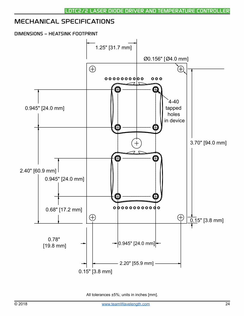
DIMENSIONS – HEATSINK FOOTPRINT
0.78"[19.8 mm] 0.945" [24.0 mm]
0.68" [17.2 mm]
0.945" [24.0 mm]2.40" [60.9 mm]
0.945" [24.0 mm]
1.25" [31.7 mm]
Ø0.156" [Ø4.0 mm]
4-40tappedholes
in device
0.15" [3.8 mm]2.20" [55.9 mm]
0.15" [3.8 mm]
3.70" [94.0 mm]
All tolerances ±5%; units in inches [mm].

© 2018 www.teamWavelength.com 25
LDTC2/2 LASER DIODE DRIVER AND TEMPERATURE CONTROLLER
CERTIFICATION AND WARRANTY
CERTIFICATION
Wavelength Electronics, Inc. (Wavelength) certifies that this product met its published specifications at the time of shipment. Wavelength further certifies that its calibration measurements are traceable to the United States National Institute of Standards and Technology, to the extent allowed by that organization’s calibration facilities, and to the calibration facilities of other International Standards Organization members.
WARRANTY
This Wavelength product is warranted against defects in materials and workmanship for a period of one (1) year from date of shipment. During the warranty period, Wavelength will, at its option, either repair or replace products which prove to be defective.
WARRANTY SERVICE
For warranty service or repair, this product must be returned to the factory. An RMA is required for products returned to Wavelength for warranty service. The Buyer shall prepay shipping charges to Wavelength and Wavelength shall pay shipping charges to return the product to the Buyer upon determination of defective materials or workmanship. However, the Buyer shall pay all shipping charges, duties, and taxes for products returned to Wavelength from another country.
LIMITATIONS OF WARRANTY
The warranty shall not apply to defects resulting from improper use or misuse of the product or operation outside published specifications. No other warranty is expressed or implied. Wavelength specifically disclaims the implied warranties of merchantability and fitness for a particular purpose.
EXCLUSIVE REMEDIES
The remedies provided herein are the Buyer’s sole and exclusive remedies. Wavelength shall not be liable for any direct, indirect, special, incidental, or consequential damages, whether based on contract, tort, or any other legal theory.
REVERSE ENGINEERING PROHIBITED
Buyer, End-User, or Third-Party Reseller are expressly prohibited from reverse engineering, decompiling, or disassembling this product.
NOTICE
The information contained in this document is subject to change without notice. Wavelength will not be liable for errors contained herein or for incidental or consequential damages in connection with the furnishing, performance, or use of this material. No part of this document may be translated to another language without the prior written consent of Wavelength.
SAFETY
There are no user-serviceable parts inside this product. Return the product to Wavelength Electronics for service and repair to ensure that safety features are maintained.
LIFE SUPPORT POLICY
This important safety information applies to all Wavelength electrical and electronic products and accessories:
As a general policy, Wavelength Electronics, Inc. does not recommend the use of any of its products in life support applications where the failure or malfunction of the Wavelength product can be reasonably expected to cause failure of the life support device or to significantly affect its safety or effectiveness. Wavelength will not knowingly sell its products for use in such applications unless it receives written assurances satisfactory to Wavelength that the risks of injury or damage have been minimized, the customer assumes all such risks, and there is no product liability for Wavelength. Examples of devices considered to be life support devices are neonatal oxygen analyzers, nerve stimulators (for any use), auto-transfusion devices, blood pumps, defibrillators, arrhythmia detectors and alarms, pacemakers, hemodialysis systems, peritoneal dialysis systems, ventilators of all types, and infusion pumps as well as other devices designated as “critical” by the FDA. The above are representative examples only and are not intended to be conclusive or exclusive of any other life support device.
REVISION HISTORY
DOCUMENT NUMBER: LDTC2-2-00400
REV. DATE CHANGE
I May 2013 Added the IPD formula for Constant Current mode.
J August 2014 Extended warranty, updated cable drawings and specification table.
K February 2016 Updated WCB301 cable diagram.
L January 2019 Updated to new format. Clarified limit-setting procedure.
51 Evergreen DriveBozeman, Montana 59715
406-587-4910 (tel)406-587-4911 (fax)
Sales & Tech [email protected]


