DE
2S
AF
ET
YS
WIT
CH
ES
DE2_P01-17.fm Page 1 Thursday, December 10, 2015 11:25 PM
Safety Switches
Selection Guide
Contents Descriptions Page
General Information• Features and Benefits 2 - 3
• Product Illustrations
General Duty, Light Duty Safety Switches & Air Conditioning Disconnects• 120/240Vac 4 - 5
Heavy Duty Safety Switches• 240Vac Fusible 6 - 7
• 600Vac Fusible & Non-Fusible 8 - 11
Heavy Duty Special Application Safety Switches• 600Vac Fusible & Non-Fusible 12 - 13
• MD Motor Disconnect Switches 14
• RCD Switches 15
Heavy Duty Receptacle Switches• 600Vac Fusible & Non-Fusible 16
1000 Vdc Photovoltaic Heavy Duty Disconnect Switch• IEC and UL98-B listed 17
• NEMA 3 and IP63 Enclosure 17
Double Throw Safety Switches• 240Vac & 600Vac Fusible & Non-Fusible 18 - 21
Accessories (Field/Factory Installed)• Heavy Duty Safety Switches 22 - 26
• Double Throw Safety Switches - E-Series 27
• Double Throw Safety Switches - F-Series 28
• General Duty Safety Switches 29
Application Information• Safety Switches Enclosures 30
DE2-111/15
DE
2S
AF
ET
YS
WIT
CH
ES
DE2_P01-17.fm Page 2 Thursday, December 10, 2015 11:25 PM
Safety SwitchesGeneral Information
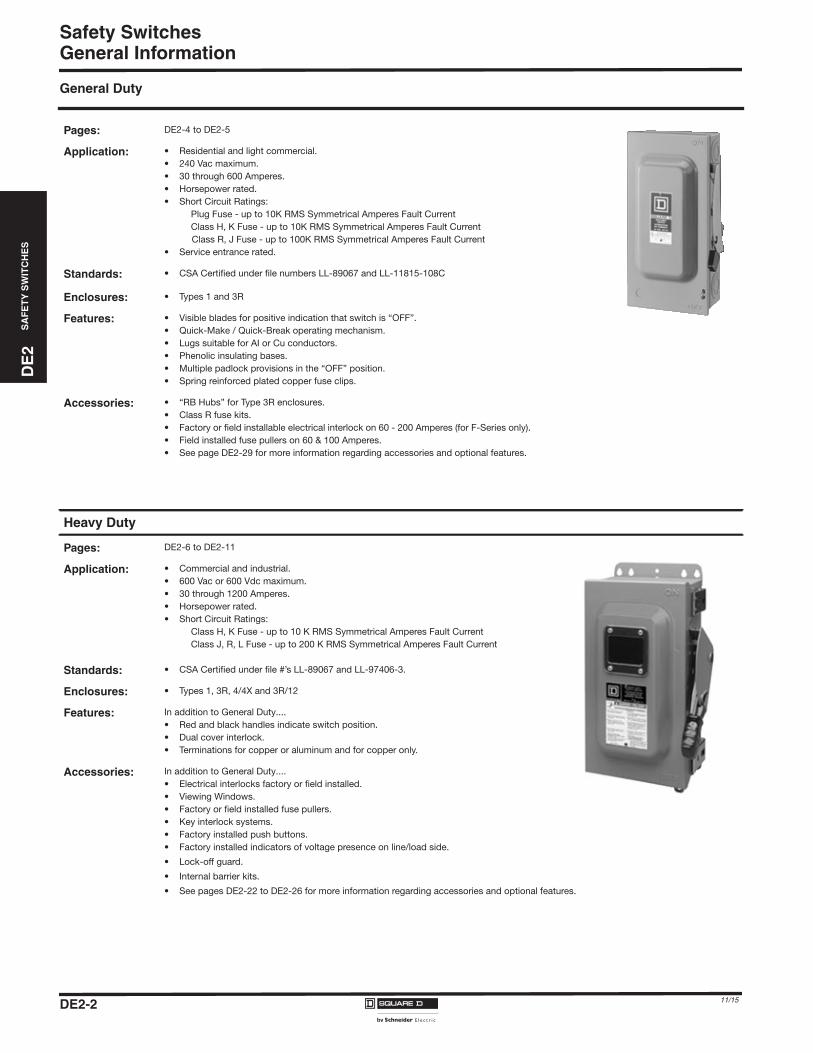
General Duty
Pages: DE2-4 to DE2-5
Application: • Residential and light commercial.
• 240 Vac maximum.
• 30 through 600 Amperes.
• Horsepower rated.
• Short Circuit Ratings:
Plug Fuse - up to 10K RMS Symmetrical Amperes Fault Current
Class H, K Fuse - up to 10K RMS Symmetrical Amperes Fault Current
Class R, J Fuse - up to 100K RMS Symmetrical Amperes Fault Current
• Service entrance rated.
Standards: • CSA Certified under file numbers LL-89067 and LL-11815-108C
Enclosures: • Types 1 and 3R
Features: • Visible blades for positive indication that switch is “OFF”.
• Quick-Make / Quick-Break operating mechanism.
• Lugs suitable for AI or Cu conductors.
• Phenolic insulating bases.
• Multiple padlock provisions in the “OFF” position.
• Spring reinforced plated copper fuse clips.
Accessories: • “RB Hubs” for Type 3R enclosures.
• Class R fuse kits.
• Factory or field installable electrical interlock on 60 - 200 Amperes (for F-Series only).
• Field installed fuse pullers on 60 & 100 Amperes.
• See page DE2-29 for more information regarding accessories and optional features.
Heavy Duty
Pages: DE2-6 to DE2-11
Application: • Commercial and industrial.
• 600 Vac or 600 Vdc maximum.
• 30 through 1200 Amperes.
• Horsepower rated.
• Short Circuit Ratings:
Class H, K Fuse - up to 10 K RMS Symmetrical Amperes Fault Current
Class J, R, L Fuse - up to 200 K RMS Symmetrical Amperes Fault Current
Standards: • CSA Certified under file #’s LL-89067 and LL-97406-3.
Enclosures: • Types 1, 3R, 4/4X and 3R/12
Features: In addition to General Duty....
• Red and black handles indicate switch position.
• Dual cover interlock.
• Terminations for copper or aluminum and for copper only.
Accessories: In addition to General Duty....
• Electrical interlocks factory or field installed.
• Viewing Windows.
• Factory or field installed fuse pullers.
• Key interlock systems.
• Factory installed push buttons.
• Factory installed indicators of voltage presence on line/load side.
• Lock-off guard.
• Internal barrier kits.
• See pages DE2-22 to DE2-26 for more information regarding accessories and optional features.
DE2-2 11/15
DE
2S
AF
ET
YS
WIT
CH
ES
DE2_P01-17.fm Page 3 Thursday, December 10, 2015 11:25 PM
Safety SwitchesGeneral Information
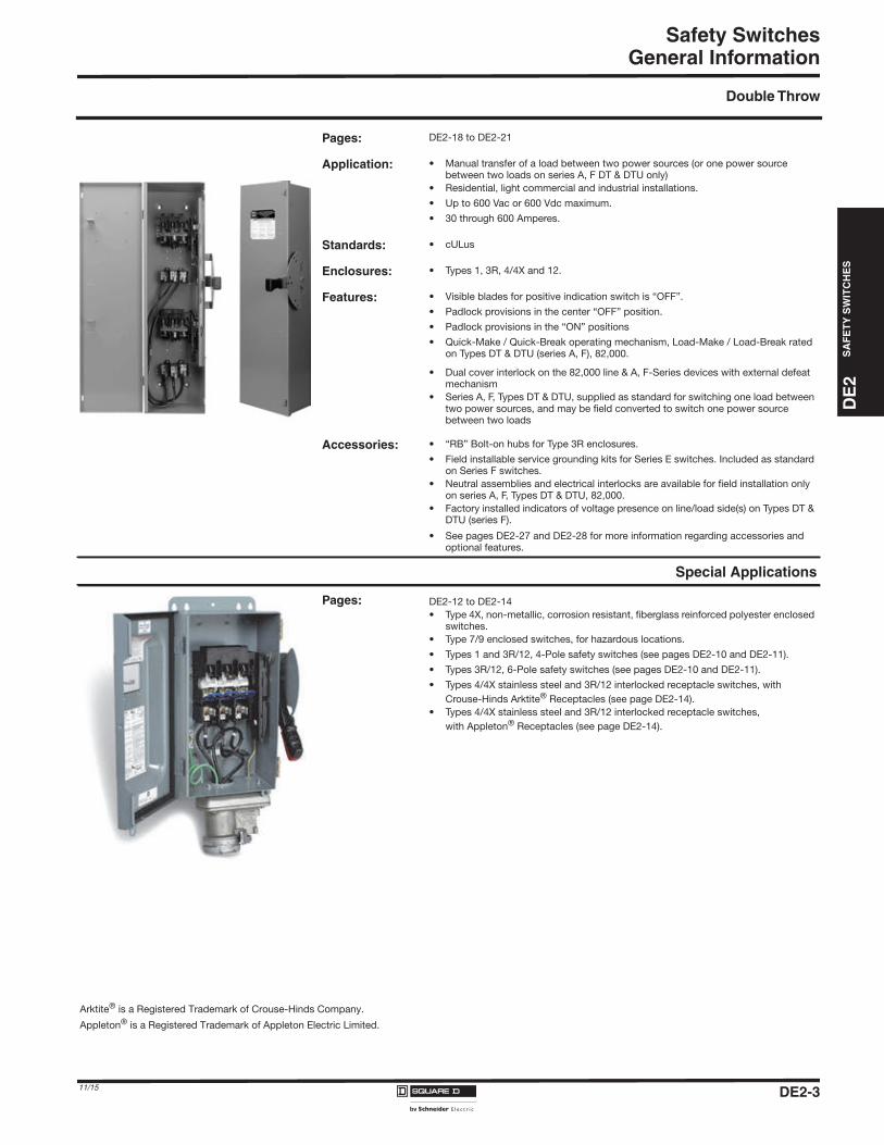
Double Throw
Pages: DE2-18 to DE2-21
Application: • Manual transfer of a load between two power sources (or one power source between two loads on series A, F DT & DTU only)
• Residential, light commercial and industrial installations.
• Up to 600 Vac or 600 Vdc maximum.
• 30 through 600 Amperes.
Standards: • cULus
Enclosures: • Types 1, 3R, 4/4X and 12.
Features: • Visible blades for positive indication switch is “OFF”.
• Padlock provisions in the center “OFF” position.
• Padlock provisions in the “ON” positions
• Quick-Make / Quick-Break operating mechanism, Load-Make / Load-Break rated on Types DT & DTU (series A, F), 82,000.
• Dual cover interlock on the 82,000 line & A, F-Series devices with external defeat mechanism
• Series A, F, Types DT & DTU, supplied as standard for switching one load between two power sources, and may be field converted to switch one power source between two loads
Accessories: • “RB” Bolt-on hubs for Type 3R enclosures.
• Field installable service grounding kits for Series E switches. Included as standard on Series F switches.
• Neutral assemblies and electrical interlocks are available for field installation only on series A, F, Types DT & DTU, 82,000.
• Factory installed indicators of voltage presence on line/load side(s) on Types DT & DTU (series F).
• See pages DE2-27 and DE2-28 for more information regarding accessories and optional features.
Special Applications
Pages: DE2-12 to DE2-14
• Type 4X, non-metallic, corrosion resistant, fiberglass reinforced polyester enclosed switches.
• Type 7/9 enclosed switches, for hazardous locations.
• Types 1 and 3R/12, 4-Pole safety switches (see pages DE2-10 and DE2-11).
• Types 3R/12, 6-Pole safety switches (see pages DE2-10 and DE2-11).
• Types 4/4X stainless steel and 3R/12 interlocked receptacle switches, with
Crouse-Hinds Arktite® Receptacles (see page DE2-14).
• Types 4/4X stainless steel and 3R/12 interlocked receptacle switches,
with Appleton® Receptacles (see page DE2-14).
Arktite® is a Registered Trademark of Crouse-Hinds Company.
Appleton® is a Registered Trademark of Appleton Electric Limited.
DE2-311/15
DE2-4
Safety SwitchesD
E2
SA
FE
TY
SW
ITC
HE
S
11/15
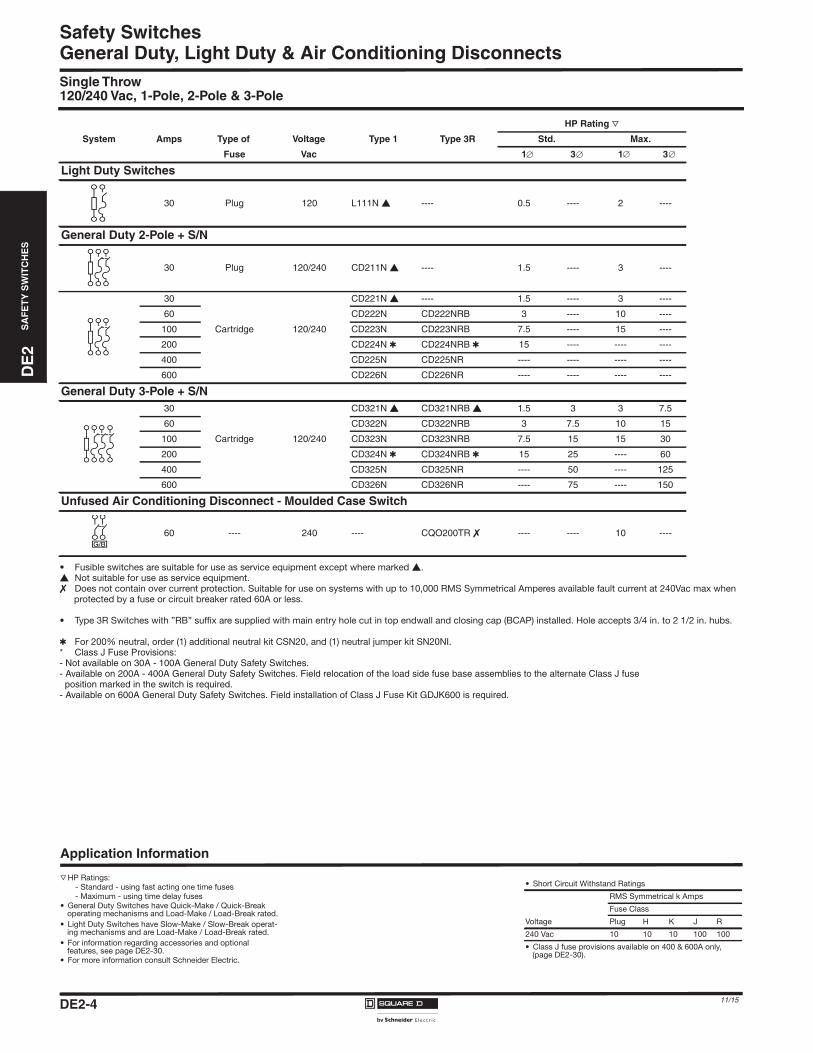
General Duty, Light Duty & Air Conditioning DisconnectsSingle Throw120/240 Vac, 1-Pole, 2-Pole & 3-Pole
• Fusible switches are suitable for use as service equipment except where marked �.� Not suitable for use as service equipment.� Does not contain over current protection. Suitable for use on systems with up to 10,000 RMS Symmetrical Amperes available fault current at 240Vac max when
protected by a fuse or circuit breaker rated 60A or less.
• Type 3R Switches with ”RB” suffix are supplied with main entry hole cut in top endwall and closing cap (BCAP) installed. Hole accepts 3/4 in. to 2 1/2 in. hubs.
� For 200% neutral, order (1) additional neutral kit CSN20, and (1) neutral jumper kit SN20NI.* Class J Fuse Provisions:- Not available on 30A - 100A General Duty Safety Switches.- Available on 200A - 400A General Duty Safety Switches. Field relocation of the load side fuse base assemblies to the alternate Class J fuseposition marked in the switch is required.
- Available on 600A General Duty Safety Switches. Field installation of Class J Fuse Kit GDJK600 is required.
HP Rating r
System Amps Type of Voltage Type 1 Type 3R Std. Max.
Fuse Vac 1 3 1 3
Light Duty Switches
30 Plug 120 L111N � ---- 0.5 ---- 2 ----
General Duty 2-Pole + S/N
30 Plug 120/240 CD211N � ---- 1.5 ---- 3 ----
30 CD221N � ---- 1.5 ---- 3 ----
60 CD222N CD222NRB 3 ---- 10 ----
100 Cartridge 120/240 CD223N CD223NRB 7.5 ---- 15 ----
200 CD224N � CD224NRB � 15 ---- ---- ----
400 CD225N CD225NR ---- ---- ---- ----
600 CD226N CD226NR ---- ---- ---- ----
General Duty 3-Pole + S/N30 CD321N � CD321NRB � 1.5 3 3 7.5
60 CD322N CD322NRB 3 7.5 10 15
100 Cartridge 120/240 CD323N CD323NRB 7.5 15 15 30
200 CD324N � CD324NRB � 15 25 ---- 60
400 CD325N CD325NR ---- 50 ---- 125
600 CD326N CD326NR ---- 75 ---- 150
Unfused Air Conditioning Disconnect - Moulded Case Switch
60 ---- 240 ---- CQO200TR � ---- ---- 10 ----
Application Information
r HP Ratings:- Standard - using fast acting one time fuses- Maximum - using time delay fuses
• General Duty Switches have Quick-Make / Quick-Break operating mechanisms and Load-Make / Load-Break rated.
• Light Duty Switches have Slow-Make / Slow-Break operat-ing mechanisms and are Load-Make / Load-Break rated.
• For information regarding accessories and optional features, see page DE2-30.
• For more information consult Schneider Electric.
• Short Circuit Withstand Ratings
RMS Symmetrical k Amps
Fuse Class
Voltage Plug H K J R
240 Vac 10 10 10 100 100
• Class J fuse provisions available on 400 & 600A only, (page DE2-30).
DE2_P01-17.fm Page 4 Thursday, December 10, 2015 11:25 PM
DE
2SA
FE
TY
SW
ITC
HE
S
DE2_P01-17.fm Page 5 Thursday, December 10, 2015 11:25 PM
Safety SwitchesGeneral Duty
Single Throw120/240 Volt
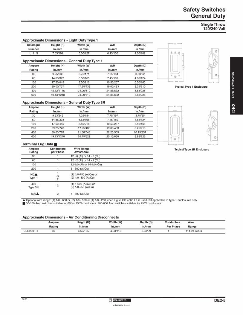
Approximate Dimensions - Light Duty Type 1Catalogue Height (H) Width (W) W/H Depth (D)
Number in./mm in./mm in./mm in./mm
L111N 7.63/194 5.00/127 6.13/156 4.00/102
Approximate Dimensions - General Duty Type 1Ampere Height (H) Width (W) W/H Depth (D)
Rating in./mm in./mm in./mm in./mm
30 9.25/235 6.75/171 7.25/184 3.63/92
60 14.63/372 6.50/165 7.45/189 4.88/124
100 17.50/445 8.50/216 10.50/267 6.50/165
200 29.00/737 17.25/438 19.00/483 8.25/210
400 45.12/1146 24.00/610 24.88/632 8.88/226
600 49.13/1248 24.00/610 24.88/632 8.88/226
Approximate Dimensions - General Duty Type 3RAmpere Height (H) Width (W) W/H Depth (D)
Rating in./mm in./mm in./mm in./mm
30 9.63/245 7.25/184 7.75/197 3.75/95
60 14.88/378 6.63/168 7.45/189 4.88/124
100 17.50/445 8.50/216 10.50/267 6.50/165
200 29.25/743 17.25/438 19.00/483 8.25/210
400 30.63/778 21.38/543 22.25/565 10.13/257
600 49.13/1248 24.75/629 25.13/638 8.88/226
Terminal Lug Data �
AmpereRating
Conductorsper Phase
Wire RangeAWG/Kcmil
30 1 12 - 6 (Al) or 14 - 6 (Cu)
60 1 12 - 2 (Al) or 14 - 2 (Cu)
100 1 12-1/0 (Al) or 14-1/0 (Cu)
200 1 6 - 300 (Al/Cu)
400�Type 1
1or2
(1) 1/0-750 (Al/Cu) or(2) 1/0- 300 (Al/Cu)
400Type 3R
2 (1) 1-600 (Al/Cu) or(2) 1/0-250 (Al/Cu)
600� 2 4 - 600 (Al/Cu)
� Optional wire range: (1) 1/0 - 600 or, (2) 1/0 - 500 or (4) 1/0 - 250 when lug kit GD 4060 LK is used. Kit applicable to Type 1 enclosures only.� 30-100 Amp switches suitable for 60º or 75ºC conductors. 200-600 Amp switches suitable for 75ºC conductors.
Typical Type 1 Enclosure
Typical Type 3R Enclosure
Approximate Dimensions - Air Conditioning DisconnectsAmpere Height (H) Width (W) Depth (D) Conductors Wire
Rating in./mm in./mm in./mm Per Phase Range
CQ0200TR 60 6.50/165 4.63/118 3.88/99 1 #14-#4 Al/Cu
DE2-511/15
DE2-6
Safety SwitchesD
E2
SA
FE
TY
SW
ITC
HE
S
11/15
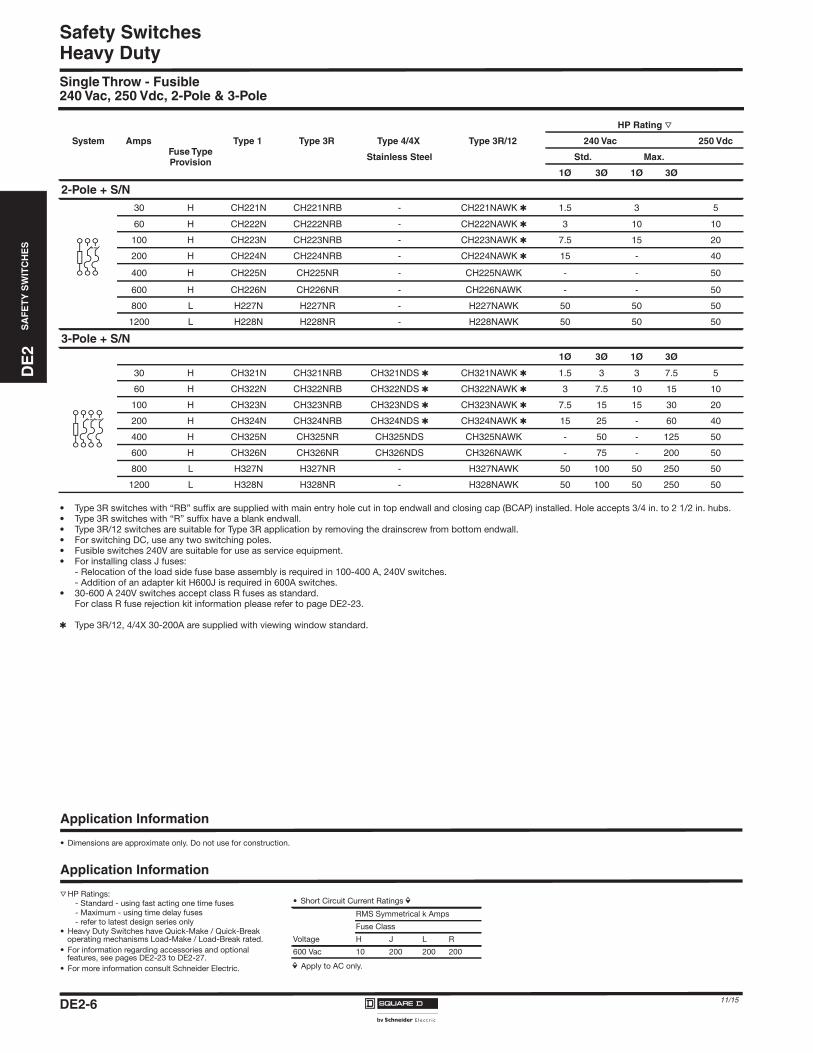
Heavy DutySingle Throw - Fusible240 Vac, 250 Vdc, 2-Pole & 3-Pole
• Type 3R switches with “RB” suffix are supplied with main entry hole cut in top endwall and closing cap (BCAP) installed. Hole accepts 3/4 in. to 2 1/2 in. hubs.• Type 3R switches with “R” suffix have a blank endwall.• Type 3R/12 switches are suitable for Type 3R application by removing the drainscrew from bottom endwall.• For switching DC, use any two switching poles.• Fusible switches 240V are suitable for use as service equipment.• For installing class J fuses:
- Relocation of the load side fuse base assembly is required in 100-400 A, 240V switches.- Addition of an adapter kit H600J is required in 600A switches.
• 30-600 A 240V switches accept class R fuses as standard. For class R fuse rejection kit information please refer to page DE2-23.
� Type 3R/12, 4/4X 30-200A are supplied with viewing window standard.
HP Rating r
System AmpsFuse TypeProvision
Type 1 Type 3R Type 4/4X Type 3R/12 240 Vac 250 Vdc
Stainless Steel Std. Max.
1Ø 3Ø 1Ø 3Ø
2-Pole + S/N30 H CH221N CH221NRB - CH221NAWK � 1.5 3 5
60 H CH222N CH222NRB - CH222NAWK � 3 10 10
100 H CH223N CH223NRB - CH223NAWK � 7.5 15 20
200 H CH224N CH224NRB - CH224NAWK � 15 - 40
400 H CH225N CH225NR - CH225NAWK - - 50
600 H CH226N CH226NR - CH226NAWK - - 50
800 L H227N H227NR - H227NAWK 50 50 50
1200 L H228N H228NR - H228NAWK 50 50 50
3-Pole + S/N1Ø 3Ø 1Ø 3Ø
30 H CH321N CH321NRB CH321NDS � CH321NAWK � 1.5 3 3 7.5 5
60 H CH322N CH322NRB CH322NDS � CH322NAWK � 3 7.5 10 15 10
100 H CH323N CH323NRB CH323NDS � CH323NAWK � 7.5 15 15 30 20
200 H CH324N CH324NRB CH324NDS � CH324NAWK � 15 25 - 60 40
400 H CH325N CH325NR CH325NDS CH325NAWK - 50 - 125 50
600 H CH326N CH326NR CH326NDS CH326NAWK - 75 - 200 50
800 L H327N H327NR - H327NAWK 50 100 50 250 50
1200 L H328N H328NR - H328NAWK 50 100 50 250 50
Application Information
• Dimensions are approximate only. Do not use for construction.
Application Information
r HP Ratings:- Standard - using fast acting one time fuses- Maximum - using time delay fuses- refer to latest design series only
• Heavy Duty Switches have Quick-Make / Quick-Break operating mechanisms Load-Make / Load-Break rated.
• For information regarding accessories and optional features, see pages DE2-23 to DE2-27.
• For more information consult Schneider Electric. i Apply to AC only.
• Short Circuit Current Ratings iRMS Symmetrical k Amps
Fuse Class
Voltage H J L R
600 Vac 10 200 200 200
DE2_P01-17.fm Page 6 Thursday, December 10, 2015 11:25 PM
DE
2S
AF
ET
YS
WIT
CH
ES
DE2_P01-17.fm Page 7 Thursday, December 10, 2015 11:25 PM
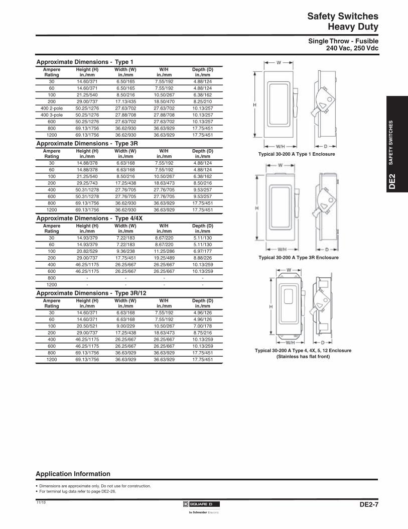
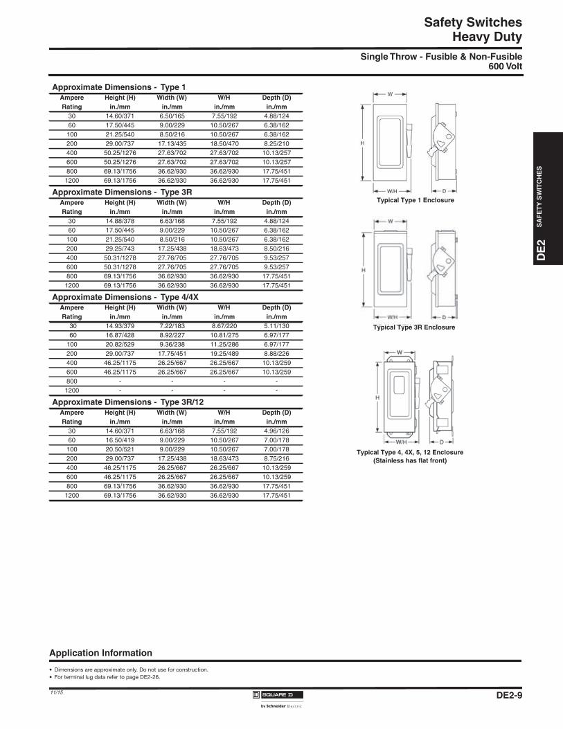
Safety SwitchesHeavy Duty
Single Throw - Fusible240 Vac, 250 Vdc
Approximate Dimensions - Type 1AmpereRating
Height (H)in./mm
Width (W)in./mm
W/Hin./mm
Depth (D)in./mm
30 14.60/371 6.50/165 7.55/192 4.88/12460 14.60/371 6.50/165 7.55/192 4.88/124100 21.25/540 8.50/216 10.50/267 6.38/162200 29.00/737 17.13/435 18.50/470 8.25/210
400 2-pole 50.25/1276 27.63/702 27.63/702 10.13/257400 3-pole 50.25/1276 27.88/708 27.88/708 10.13/257
600 50.25/1276 27.63/702 27.63/702 10.13/257800 69.13/1756 36.62/930 36.63/929 17.75/451
1200 69.13/1756 36.62/930 36.63/929 17.75/451
Approximate Dimensions - Type 3RAmpereRating
Height (H)in./mm
Width (W)in./mm
W/Hin./mm
Depth (D)in./mm
30 14.88/378 6.63/168 7.55/192 4.88/12460 14.88/378 6.63/168 7.55/192 4.88/124100 21.25/540 8.50/216 10.50/267 6.38/162200 29.25/743 17.25/438 18.63/473 8.50/216400 50.31/1278 27.76/705 27.76/705 9.53/257600 50.31/1278 27.76/705 27.76/705 9.53/257800 69.13/1756 36.62/930 36.63/929 17.75/451
1200 69.13/1756 36.62/930 36.63/929 17.75/451
Approximate Dimensions - Type 4/4XAmpereRating
Height (H)in./mm
Width (W)in./mm
W/Hin./mm
Depth (D)in./mm
30 14.93/379 7.22/183 8.67/220 5.11/13060 14.93/379 7.22/183 8.67/220 5.11/130
100 20.82/529 9.36/238 11.25/286 6.97/177200 29.00/737 17.75/451 19.25/489 8.88/226400 46.25/1175 26.25/667 26.25/667 10.13/259600 46.25/1175 26.25/667 26.25/667 10.13/259800 - - - -
1200 - - - -
Approximate Dimensions - Type 3R/12AmpereRating
Height (H)in./mm
Width (W)in./mm
W/Hin./mm
Depth (D)in./mm
30 14.60/371 6.63/168 7.55/192 4.96/12660 14.60/371 6.63/168 7.55/192 4.96/126100 20.50/521 9.00/229 10.50/267 7.00/178200 29.00/737 17.25/438 18.63/473 8.75/216400 46.25/1175 26.25/667 26.25/667 10.13/259600 46.25/1175 26.25/667 26.25/667 10.13/259800 69.13/1756 36.63/929 36.63/929 17.75/451
1200 69.13/1756 36.63/929 36.63/929 17.75/451
Typical 30-200 A Type 1 Enclosure
Application Information
• Dimensions are approximate only. Do not use for construction.
• For terminal lug data refer to page DE2-26.
Typical 30-200 A Type 4, 4X, 5, 12 Enclosure(Stainless has flat front)
Typical 30-200 A Type 3R Enclosure
DE2-711/15
DE2-8
Safety SwitchesD
E2
SA
FE
TY
SW
ITC
HE
S
11/15
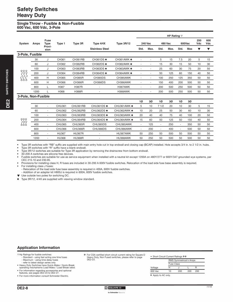
Heavy DutySingle Throw - Fusible & Non-Fusible600 Vac, 600 Vdc, 3-Pole
• Type 3R switches with “RB” suffix are supplied with main entry hole cut in top endwall and closing cap (BCAP) installed. Hole accepts 3/4 in. to 2 1/2 in. hubs.• Type 3R switches with “R” suffix have a blank endwall.• Type 3R/12 switches are suitable for Type 3R application by removing the drainscrew from bottom endwall.• 30-200 A switches are silicone free devices. • Fusible switches are suitable for use as service equipment when installed with a neutral kit except 1200A on 480Y/277 or 600Y/347 grounded wye systems, per
CEC 215.10 and 230.95.• Provisions for installing class H, R fuses are included in 30-200 A 600V fusible switches. Relocation of the load side fuse base assembly is required.• For installing class J fuses:
- Relocation of the load side fuse base assembly is required in 400A, 600V fusible switches.- Addition of an adapter kit H600J is required in 600A, 600V fusible switches.
� Use outside two poles for switching DC.� Type 3R/12, 4/4X are supplied with viewing window standard.
HP Rating r
System AmpsFuseTypeProvi-sion
Type 1 Type 3R Type 4/4X Type 3R/12 240 Vac 480 Vac 600Vac250Vdc
600Vdc
Stainless Steel Std. Max. Std. Max. Std. Max � �
3-Pole, Fusible30 J CH361 CH361RB CH361DS � CH361AWK � - - 5 15 7.5 20 5 15
60 J CH362 CH362RB CH362DS � CH362AWK � - - 15 30 15 50 10 30
100 J CH363 CH363RB CH363DS � CH363AWK � - - 25 60 30 75 20 50
200 J CH364 CH364RB CH364DS � CH364AWK � - - 50 125 60 150 40 50
400 H CH365 CH365R CH365DS CH365AWK - - 100 250 125 350 50 50
600 H CH366 CH366R CH366DS CH366AWK - - 150 400 200 500 50 50
800 L H367 H367R - H367AWK - - 200 500 250 500 50 50
1200 L H368 H368R - H368AWK - - 200 500 250 500 50 50
3-Pole, Non-Fusible1Ø 3Ø 1Ø 3Ø 1Ø 3Ø
30 - CHU361 CHU361RB CHU361DS � CHU361AWK � 5 10 7 1/2 20 10 30 5 15
60 - CHU362 CHU362RB CHU362DS � CHU362AWK � 10 20 25 50 30 60 10 30
100 - CHU363 CHU363RB CHU363DS � CHU363AWK � 20 40 40 75 40 100 20 50
200 - CHU364 CHU364RB CHU364DS � CHU364AWK � 15 60 50 125 50 150 40 50
400 - CHU365 CHU365R CHU365DS CHU365AWK - 125 - 250 - 350 50 50
600 - CHU366 CHU366R CHU366DS CHU366AWK - 200 - 400 - 500 50 50
800 - HU367 HU367R - HU367AWK 50 250 50 500 50 500 50 50
1200 - HU368 HU368R - HU368AWK 50 250 50 500 50 500 50 50
Application Information
r Hp Ratings for fusible switches:- Standard - using fast acting one time fuses- Maximum - using time delay fuses- refer to latest design series only
• Heavy Duty Switches have Quick-Make / Quick-Break operating mechanisms Load-Make / Load-Break rated.
• For information regarding accessories and optional features, see pages DE2-23 to DE2-27.
• For more information consult Schneider Electric.
l For CSA certified short-circuit current rating for Square D Heavy Duty, Non Fused switches, please refer to page DE2-23.
i Apply to AC only.
• Short Circuit Current Ratings l iRMS Symmetrical k Amps
Fuse Class
Voltage H J L R
600 Vac 10 200 200 200
DE2_P01-17.fm Page 8 Thursday, December 10, 2015 11:25 PM
DE
2S
AF
ET
YS
WIT
CH
ES
DE2_P01-17.fm Page 9 Thursday, December 10, 2015 11:25 PM
Safety SwitchesHeavy Duty
Single Throw - Fusible & Non-Fusible600 Volt
Approximate Dimensions - Type 1Ampere Height (H) Width (W) W/H Depth (D)Rating in./mm in./mm in./mm in./mm
30 14.60/371 6.50/165 7.55/192 4.88/12460 17.50/445 9.00/229 10.50/267 6.38/162
100 21.25/540 8.50/216 10.50/267 6.38/162200 29.00/737 17.13/435 18.50/470 8.25/210400 50.25/1276 27.63/702 27.63/702 10.13/257600 50.25/1276 27.63/702 27.63/702 10.13/257800 69.13/1756 36.62/930 36.62/930 17.75/4511200 69.13/1756 36.62/930 36.62/930 17.75/451
Approximate Dimensions - Type 3RAmpere Height (H) Width (W) W/H Depth (D)Rating in./mm in./mm in./mm in./mm
30 14.88/378 6.63/168 7.55/192 4.88/12460 17.50/445 9.00/229 10.50/267 6.38/162
100 21.25/540 8.50/216 10.50/267 6.38/162200 29.25/743 17.25/438 18.63/473 8.50/216400 50.31/1278 27.76/705 27.76/705 9.53/257600 50.31/1278 27.76/705 27.76/705 9.53/257800 69.13/1756 36.62/930 36.62/930 17.75/4511200 69.13/1756 36.62/930 36.62/930 17.75/451
Approximate Dimensions - Type 4/4XAmpere Height (H) Width (W) W/H Depth (D)Rating in./mm in./mm in./mm in./mm
30 14.93/379 7.22/183 8.67/220 5.11/13060 16.87/428 8.92/227 10.81/275 6.97/177
100 20.82/529 9.36/238 11.25/286 6.97/177200 29.00/737 17.75/451 19.25/489 8.88/226400 46.25/1175 26.25/667 26.25/667 10.13/259600 46.25/1175 26.25/667 26.25/667 10.13/259800 - - - -1200 - - - -
Approximate Dimensions - Type 3R/12Ampere Height (H) Width (W) W/H Depth (D)Rating in./mm in./mm in./mm in./mm
30 14.60/371 6.63/168 7.55/192 4.96/12660 16.50/419 9.00/229 10.50/267 7.00/178
100 20.50/521 9.00/229 10.50/267 7.00/178200 29.00/737 17.25/438 18.63/473 8.75/216400 46.25/1175 26.25/667 26.25/667 10.13/259600 46.25/1175 26.25/667 26.25/667 10.13/259800 69.13/1756 36.62/930 36.62/930 17.75/4511200 69.13/1756 36.62/930 36.62/930 17.75/451
Typical Type 1 Enclosure
Typical Type 3R Enclosure
Application Information
• Dimensions are approximate only. Do not use for construction.
• For terminal lug data refer to page DE2-26.
Typical Type 4, 4X, 5, 12 Enclosure(Stainless has flat front)
DE2-911/15
DE2-10
Safety SwitchesD
E2
SA
FE
TY
SW
ITC
HE
S
11/15
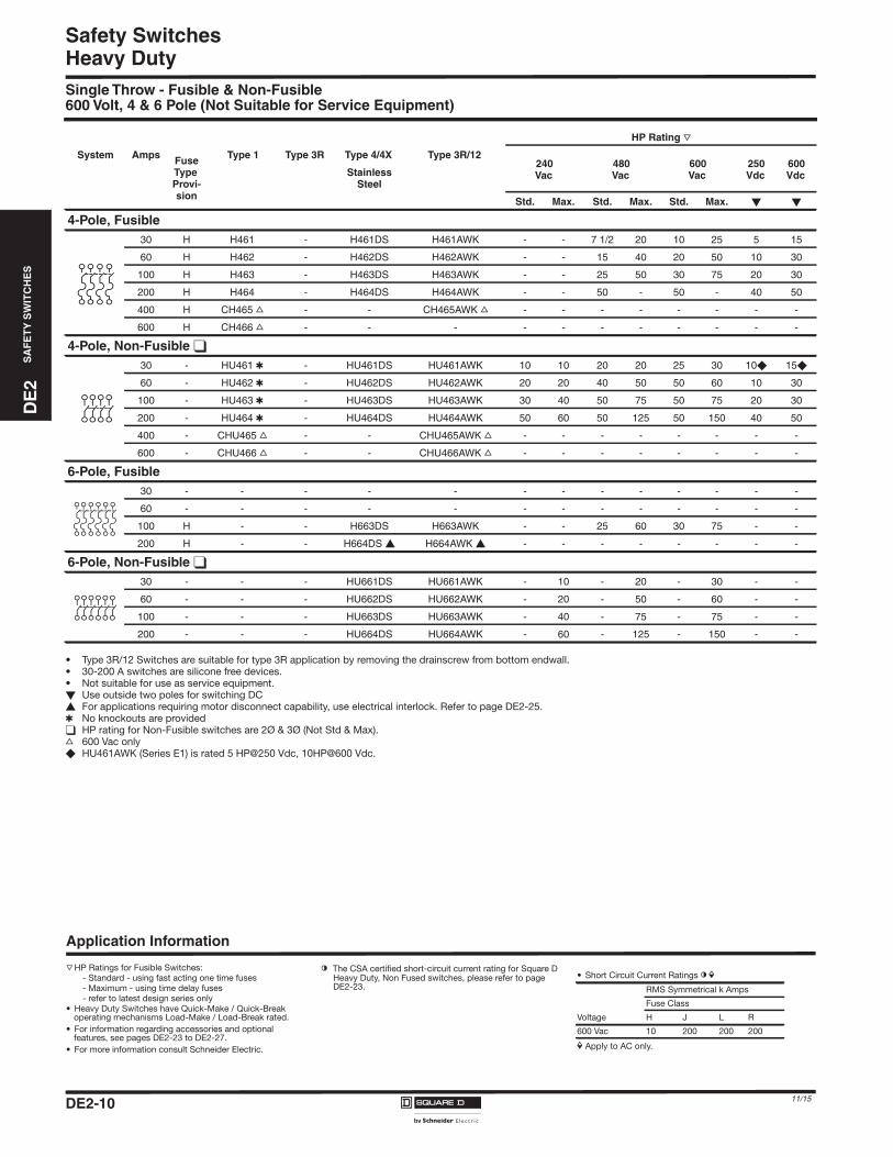
Heavy DutySingle Throw - Fusible & Non-Fusible600 Volt, 4 & 6 Pole (Not Suitable for Service Equipment)
• Type 3R/12 Switches are suitable for type 3R application by removing the drainscrew from bottom endwall.• 30-200 A switches are silicone free devices.• Not suitable for use as service equipment.� Use outside two poles for switching DC� For applications requiring motor disconnect capability, use electrical interlock. Refer to page DE2-25.� No knockouts are provided� HP rating for Non-Fusible switches are 2Ø & 3Ø (Not Std & Max).s 600 Vac only� HU461AWK (Series E1) is rated 5 HP@250 Vdc, 10HP@600 Vdc.
HP Rating r
System Amps FuseTypeProvi-sion
Type 1 Type 3R Type 4/4X Type 3R/12240Vac
480Vac
600Vac
250Vdc
600VdcStainless
Steel
Std. Max. Std. Max. Std. Max. � �
4-Pole, Fusible30 H H461 - H461DS H461AWK - - 7 1/2 20 10 25 5 15
60 H H462 - H462DS H462AWK - - 15 40 20 50 10 30
100 H H463 - H463DS H463AWK - - 25 50 30 75 20 30
200 H H464 - H464DS H464AWK - - 50 - 50 - 40 50
400 H CH465 s - - CH465AWK s - - - - - - - -
600 H CH466 s - - - - - - - - - - -
4-Pole, Non-Fusible �
30 - HU461 � - HU461DS HU461AWK 10 10 20 20 25 30 10� 15�
60 - HU462 � - HU462DS HU462AWK 20 20 40 50 50 60 10 30
100 - HU463 � - HU463DS HU463AWK 30 40 50 75 50 75 20 30
200 - HU464 � - HU464DS HU464AWK 50 60 50 125 50 150 40 50
400 - CHU465 s - - CHU465AWK s - - - - - - - -
600 - CHU466 s - - CHU466AWK s - - - - - - - -
6-Pole, Fusible30 - - - - - - - - - - - - -
60 - - - - - - - - - - - - -
100 H - - H663DS H663AWK - - 25 60 30 75 - -
200 H - - H664DS � H664AWK � - - - - - - - -
6-Pole, Non-Fusible �
30 - - - HU661DS HU661AWK - 10 - 20 - 30 - -
60 - - - HU662DS HU662AWK - 20 - 50 - 60 - -
100 - - - HU663DS HU663AWK - 40 - 75 - 75 - -
200 - - - HU664DS HU664AWK - 60 - 125 - 150 - -
Application Information
r HP Ratings for Fusible Switches:- Standard - using fast acting one time fuses- Maximum - using time delay fuses- refer to latest design series only
• Heavy Duty Switches have Quick-Make / Quick-Break operating mechanisms Load-Make / Load-Break rated.
• For information regarding accessories and optional features, see pages DE2-23 to DE2-27.
• For more information consult Schneider Electric.
l The CSA certified short-circuit current rating for Square D Heavy Duty, Non Fused switches, please refer to page DE2-23.
• Short Circuit Current Ratings l iRMS Symmetrical k Amps
Fuse Class
Voltage H J L R
600 Vac 10 200 200 200
i Apply to AC only.
DE2_P01-17.fm Page 10 Thursday, December 10, 2015 11:25 PM
DE
2S
AF
ET
YS
WIT
CH
ES
DE2_P01-17.fm Page 11 Thursday, December 10, 2015 11:25 PM
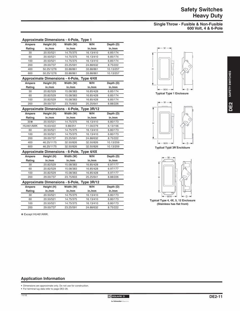
Safety SwitchesHeavy Duty
Single Throw - Fusible & Non-Fusible600 Volt, 4 & 6-Pole
Except HU461AWK.
Approximate Dimensions - 4-Pole, Type 1Ampere Height (H) Width (W) W/H Depth (D)
Rating in./mm in./mm in./mm in./mm
30 20.50/521 14.75/375 16.13/410 6.85/174
60 20.50/521 14.75/375 16.13/410 6.85/174
100 20.50/521 14.75/375 16.13/410 6.85/174
200 29.00/737 23.25/591 24.88/632 8.75/222
400 50.25/1276 33.88/861 33.88/861 10.13/257
600 50.25/1276 33.88/861 33.88/861 10.13/257
Approximate Dimensions - 4-Pole, Type 4/4XAmpere Height (H) Width (W) W/H Depth (D)
Rating in./mm in./mm in./mm in./mm
30 20.82/529 15.08/383 16.85/428 6.85/174
60 20.82/529 15.08/383 16.85/428 6.85/174
100 20.82/529 15.08/383 16.85/428 6.85/174
200 29.00/737 23.75/603 25.25/641 8.88/226
Approximate Dimensions - 4-Pole, Type 3R/12Ampere Height (H) Width (W) W/H Depth (D)
Rating in./mm in./mm in./mm in./mm
30 20.50/521 14.75/375 16.13/410 6.80/173
HU461AWK 16.63/422 9.88/251 11.00/279 6.13/156
60 20.50/521 14.75/375 16.13/410 6.80/173
100 20.50/521 14.75/375 16.13/410 6.80/173
200 29.00/737 23.25/591 24.88/632 8.75/222
400 46.25/1175 32.50/826 32.50/826 10.13/259
600 46.25/1175 32.50/826 32.50/826 10.13/259
Approximate Dimensions - 6-Pole, Type 4/4XAmpere Height (H) Width (W) W/H Depth (D)
Rating in./mm in./mm in./mm in./mm
30 20.82/529 15.08/383 16.85/428 6.97/177
60 20.82/529 15.08/383 16.85/428 6.97/177
100 20.82/529 15.08/383 16.85/428 6.97/177
200 29.00/737 23.75/603 25.25/641 8.88/226
Approximate Dimensions - 6-Pole, Type 3R/12Ampere Height (H) Width (W) W/H Depth (D)
Rating in./mm in./mm in./mm in./mm
30 20.50/521 14.75/375 16.13/410 6.80/173
60 20.50/521 14.75/375 16.13/410 6.80/173
100 20.50/521 14.75/375 16.13/410 6.80/173
200 29.00/737 23.25/591 24.88/632 8.75/222
Typical Type 1 Enclosure
Typical Type 3R Enclosure
Application Information
• Dimensions are approximate only. Do not use for construction.
• For terminal lug data refer to page DE2-26.
Typical Type 4, 4X, 5, 12 Enclosure(Stainless has flat front)
DE2-1111/15
DE2-12
Safety SwitchesD
E2
SA
FE
TY
SW
ITC
HE
S
11/15
Heavy Duty, Special ApplicationSingle Throw600 Volt, 3-Pole
316 Grade Stainless Steel–Type 3, 3R, 4, 4X, 5, 12
Type 316 stainless steel enclosure safety switches offer superior corrosion resistance to a wider range of chemicals than Type 304 stainless switches. Type 316 resists chloride attacks and is often used in marine, waste treatment and transportation applications. Use watertight hubs from page DE2-26. Equipment ground lugs are supplied as standard. (For Type 304 stainless switches see page DE2-8.) Fusible switches are suitable for use as service equipment when installed with a neutral kit.
3-pole 600 Vac, 600 Vdc
Fiberglass Reinforced Polyester Enclosures - Type 4X
Fiberglass Reinforced Polyester enclosures are watertight, corrosion resistant and impervious to windblown dust, rain, and splashing liquid. The moulded fiberglass isextremely stable in a wide range of operating temperatures and can withstand heavy impact. Switches are furnished with hubs and equipment ground lugs. Fusibleswitches are suitable for use as service equipment when installed with a neutral kit.
� Includes PKDB-1, breather and drain kit, required for rain proof application - Type 7 only.Electrical Interlocks not available. For auxiliary switches, add 1212 suffix to standard switch catalogue number and price adder (e.g. H60XFA1212)
Auxiliary Interlocks factory Installed only.
� Not CSA certified or UL listed due to wire bending space requirements.� cULus listed.
HP Rating 3Ø r
System Amps Fuse TypeProvision
CatalogueNumber
480 Vac 600 Vac 600 VdcStd. Max. Std. Max. Max.
Fusible30 H H361SS 5 15 7.5 20 1560 H H362SS 15 30 15 50 30
100 H H363SS 25 60 30 75 50200 H H364SS 50 125 60 150 50
Non-Fusible
30 - HU361SS - 20 - 30 1560 - HU362SS - 50 - 60 30
100 - HU363SS - 75 - 100 50200 - HU364SS - 125 - 150 50
HP Rating 3Ø
System Amps Fuse TypeProvision
CatalogueNumber
480 Vac 600 Vac 600 VdcStd. Max. Std. Max. Max.
Fusible30 H H361DF 5 15 7.5 20 1560 H H362DF 15 30 15 50 30
100 H H363DF 25 60 30 75 50200 H H364DF 50 125 60 150 50
Non-Fusible30 - HU361DF - 20 - 30 1560 - HU362DF - 50 - 60 30100 - HU363DF - 75 - 100 50200 - HU364DF - 125 - - 50
Type 7/9 EnclosuresAn enclosed automatic moulded case switch for use in a Class I, Groups C & D. Division 1 or 2, (Type 7); Class II, Groups E, F, & G, Division 1 or 2, (Type 9); or Class III, Division 1 or 2, (Type 9). Furnished with threaded conduit openings in both top and bottom endwallNot suitable for use as service equipment, and listed as “Raintight” for outdoor applications.3-Pole, Unfused, 600Vac, 250Vdc Maximum, Short Circuit Rating 10 000 AIR.
HP Rating 3Ø
System Amps CatalogueNumber
240 Vac 480 Vac 600 Vac
60 H60XFA �� 15 30 50
100 H100XFA �� 30 60 75
225A H225XJG �� 60 125 150
Application Information
r HP Ratings:- Standard - using fast acting one time fuses- Maximum - using time delay fuses- refer to latest design series only
• Heavy Duty Switches have Quick-Make / Quick-Break operating mechanisms Load-Make / Load-Break rated.
• For information regarding accessories and optional features, see pages DE2-23 to DE2-27.
• For more information consult Schneider Electric.
l The CSA certified short-circuit current rating for Square D Heavy Duty, Non Fused switches is based on the switch being used in conjunction with fuses. Evaluation of not fused switches in conjunction with molded case circuit breakers has not been performed. If a CSA certified short-circuit current rating is required, this not fused switch must be replaced with a SQUARE D Heavy Duty Fusible safety switch equipped with the appropriate class and size fus-ing. Consult the wiring diagram of the switch to verify the CSA certified short-circuit current rating.
• Short Circuit Current Ratings l iRMS Symmetrical k Amps
Fuse Class
Voltage H J L R
600 Vac 10 200 200 200
i Apply to AC only.
DE2_P01-17.fm Page 12 Thursday, December 10, 2015 11:25 PM
DE
2S
AF
ET
YS
WIT
CH
ES
DE2_P01-17.fm Page 13 Thursday, December 10, 2015 11:25 PM
Safety SwitchesHeavy Duty, Special Application
Single Throw600 Volt, 3-Pole
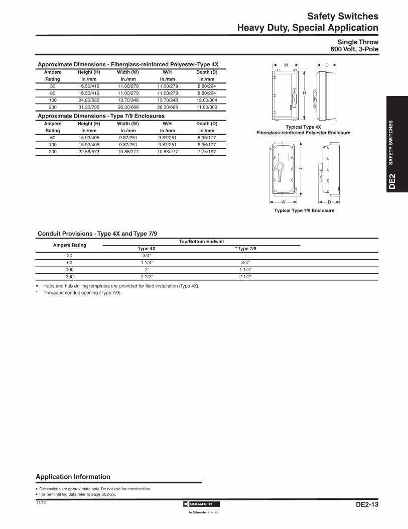
• Hubs and hub drilling templates are provided for field installation (Type 4X).
* Threaded conduit opening (Type 7/9).
Approximate Dimensions - Fiberglass-reinforced Polyester-Type 4XAmpere Height (H) Width (W) W/H Depth (D)
Rating in./mm in./mm in./mm in./mm
30 16.50/419 11.00/279 11.00/279 8.80/224
60 16.50/419 11.00/279 11.00/279 8.80/224
100 24.80/630 13.70/348 13.70/348 12.00/304
200 31.30/795 26.30/668 26.30/668 11.80/300
Approximate Dimensions - Type 7/9 EnclosuresAmpere Height (H) Width (W) W/H Depth (D)
Rating in./mm in./mm in./mm in./mm
60 15.93/405 9.87/251 9.87/251 6.96/177
100 15.93/405 9.87/251 9.87/251 6.96/177
200 22.56/573 10.88/277 10.88/277 7.75/197
Conduit Provisions - Type 4X and Type 7/9
Ampere RatingTop/Bottom Endwall
Type 4X * Type 7/9
30 3/4” -
60 1 1/4” 3/4”
100 2” 1 1/4”
200 2 1/2” 2 1/2”
H
W D
H
W D
Typical Type 4XFibreglass-reinforced Polyester Enclosure
Typical Type 7/9 Enclosure
Application Information
• Dimensions are approximate only. Do not use for construction.
• For terminal lug data refer to page DE2-26.
DE2-1311/15
DE
2S
AF
ET
YS
WIT
CH
ES
DE2_P01-17.fm Page 14 Thursday, December 10, 2015 11:25 PM
Safety SwitchesHeavy Duty, Special Application
Motor Disconnect Switches
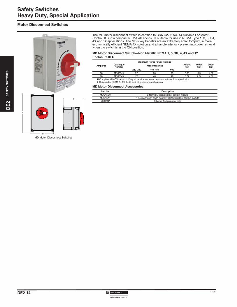
The MD motor disconnect switch is certified to CSA C22.2 No. 14 Suitable For MotorControl. It is in a compact NEMA 4X enclosure suitable for use in NEMA Type 1, 3, 3R, 4,4X and 12 applications. The MD's key benefits are an extremely small footprint, a moreeconomically efficient NEMA 4X solution and a handle interlock preventing cover removalwhen the switch is in the ON position.
■ Complies with OSHA lockout/tagout requirements—accepts up to three 8 mm padlocks.◆ Suitable for NEMA 1, 3R, 4, 4X and 12 enclosure applications.
D
H
W
MD Motor Disconnect Switches
MD Motor Disconnect Switch—Non Metallic NEMA 1, 3, 3R, 4, 4X and 12Enclosure ■ ◆
Amperes CatalogueNumber
Maximum Horse Power RatingsHeight
(in.)Width(in.)
Depth(in.)Three Phase Vac
220–240 440–480 600
30 MD3304X 7.5 20 25 6.38 3.9 4.3760 MD3604X 20 40 40 8.27 4.94 4.37
MD Motor Disconnect AccessoriesCat. No. Description
MDSAN20 2 Normally open auxiliary contact moduleMDSAN11 1 normally open and 1 normally closed auxiliary contact moduleMDS30P 30 Amp Add on power pole
DE2-14 11/15
DE2-15
DE
2S
AF
ET
YS
WIT
CH
ES
Safety Switches
11/15
Heavy Duty, Special Application
RCD Switches
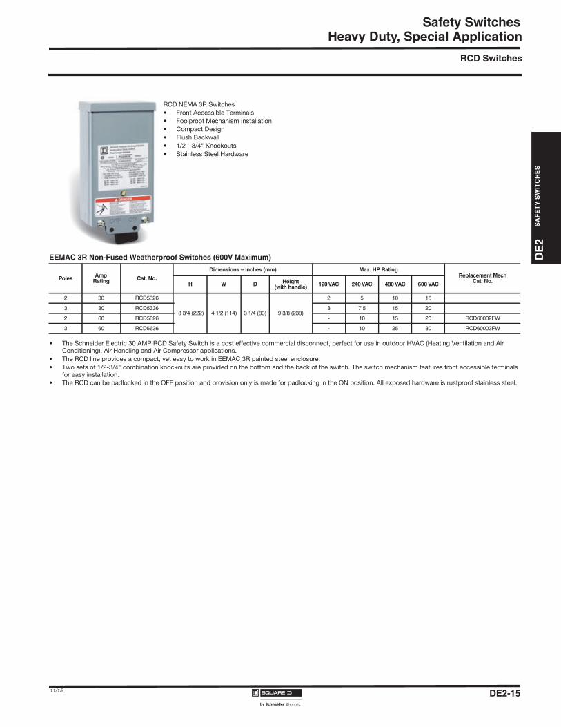
• The Schneider Electric 30 AMP RCD Safety Switch is a cost effective commercial disconnect, perfect for use in outdoor HVAC (Heating Ventilation and Air Conditioning), Air Handling and Air Compressor applications.
• The RCD line provides a compact, yet easy to work in EEMAC 3R painted steel enclosure.
• Two sets of 1/2-3/4" combination knockouts are provided on the bottom and the back of the switch. The switch mechanism features front accessible terminals for easy installation.
• The RCD can be padlocked in the OFF position and provision only is made for padlocking in the ON position. All exposed hardware is rustproof stainless steel.
RCD NEMA 3R Switches
• Front Accessible Terminals
• Foolproof Mechanism Installation
• Compact Design
• Flush Backwall
• 1/2 - 3/4" Knockouts
• Stainless Steel Hardware
EEMAC 3R Non-Fused Weatherproof Switches (600V Maximum)
PolesAmp
RatingCat. No.
Dimensions – inches (mm) Max. HP RatingReplacement Mech
Cat. No.H W D
Height(with handle)
120 VAC 240 VAC 480 VAC 600 VAC
2 30 RCD5326
8 3/4 (222) 4 1/2 (114) 3 1/4 (83) 9 3/8 (238)
2 5 10 15
3 30 RCD5336 3 7.5 15 20
2 60 RCD5626 - 10 15 20 RCD60002FW
3 60 RCD5636 - 10 25 30 RCD60003FW
DE2_P01-17.fm Page 15 Thursday, December 10, 2015 11:25 PM
DE2-16
Safety SwitchesD
E2
SA
FE
TY
SW
ITC
HE
S
11/15
Heavy Duty Receptacle SwitchesSingle Throw600 Volt, 3-Pole
• Type 3R/12 switches are suitable for Type 3R application by removing the drainscrew from bottom endwall.• Interlocking linkage between receptacle and switch mechanism prevents the insertion or removal of the plug while the switch is in the “ON” position, or the insertion of a plug other than
specified. Interlocking linkage also prevents the switch from being thrown into the “ON” position while the plug is removed.• Fusible switches are suitable for use as service equipment.� Type 3R/12, 4/4X are supplied with viewing window standard..
Receptacle Switches with Appleton Receptacles�
3-PoleHP Ratings - 3ø r
Fuse TypeProvision Type 3R/12 Type 4/4X
(Stainless Steel)Use with Apple-
ton Plug480 Vac 600 Vac 250 Vdc
System Amps Std. Max. Std. Max. Std. Max.Fusible
30 H H361AWAVW � H361DSWAVW � ACP3034BC 5 15 7 1/2 20 5 -60 H H362AWAVW � H362DSWAVW � ACP6034BC 15 30 15 50 10 -
100 H H363AWAVW � H363DSWAVW � ACP1034CD 25 60 30 75 20 -Non-Fusible
30 - HU361AWAVW � HU361DSWAVW � ACP3034BC - 20 - 30 - 560 - HU362AWAVW � HU362DSWAVW � ACP6034BC - 50 - 60 - 10100 - HU363AWAVW � HU363DSWAVW � ACP1034CD - 75 - 100 - 20
� Classified for use with Crouse-Hinds Arktite® plugs
Receptacle Switches with Crouse-Hinds Receptacles3-Pole
HP Rating - 3ø r
Fuse TypeProvision Type 3R/12 Type 4/4X
(Stainless Steel)Use with
Crouse-Hinds Plug480 Vac 600 Vac
System Amps Std. Max. Std. Max.Fusible
30 J CH361AWC � CH361DSWC � APJ3485 5 15 7 1/2 2060 J CH362AWC � CH362DSWC � APJ6485 15 30 15 50
100 J CH363AWC � CH363DSWC � APJ10487 - 60 - 75
Non-Fusible30 - CHU361AWC � CHU361DSWC � APJ3485 - 20 - 3060 - CHU362AWC � CHU362DSWC � APJ6485 - 50 - 60100 - CHU363AWC � CHU363DSWC � APJ10487 - 60 - 75
DE2_P01-17.fm Page 16 Thursday, December 10, 2015 11:25 PM
DE
2S
AF
ET
YS
WIT
CH
ES
DE2_P01-17.fm Page 17 Thursday, December 10, 2015 11:25 PM
DE2-17
Safety Switches
11/15
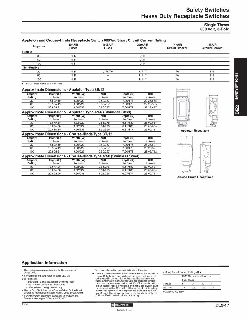
Heavy Duty Receptacle SwitchesSingle Throw
600 Volt, 3-Pole
� SCCR when using 60A Max Fuse.
Appleton and Crouse-Hinds Receptacle Switch 600Vac Short Circuit Current Rating
Amperes 10kAIRFuses
100kAIRFuses
200kAIRFuses
14kAIRCircuit Breaker
18kAIRCircuit Breaker
Fusible30 H, K – J, R – –60 H, K – J, R – –
100 H, K – J, R – –Non-Fusible
30 H, K J, R, T� J, R, T FA FH60 H, K – J, R, T FA FH
100 H, K – J, R, T FA FH
Approximate Dimensions - Appleton Type 3R/12
Appleton Receptacle
Crouse-Hinds Receptacle
AmpereRating
Height (H)in./mm
Width (W)in./mm
W/Hin./mm
Depth (D)in./mm
H/Rin./mm
30 16.50/419 9.00/229 10.50/267 7.00/178 22.25/56560 16.50/419 9.00/229 10.50/267 7.00/178 22.25/565
100 20.50/521 9.00/229 10.50/267 7.00/178 26.25/667
Approximate Dimensions - Appleton Type 4/4X (Stainless Steel)AmpereRating
Height (H)in./mm
Width (W)in./mm
W/Hin./mm
Depth (D)in./mm
H/Rin./mm
30 16.87/428 8.92/227 10.81/275 5.11/130 23.00/58460 16.87/428 8.92/227 10.81/275 5.11/130 23.00/584
100 20.82/529 9.36/238 11.25/286 6.97/177 28.00/711
Approximate Dimensions - Crouse-Hinds Type 3R/12AmpereRating
Height (H)in./mm
Width (W)in./mm
W/Hin./mm
Depth (D)in./mm
H/Rin./mm
30 16.50/419 9.00/229 10.50/267 7.00/178 23.25/59160 16.50/419 9.00/229 10.50/267 7.00/178 23.25/591
100 20.50/521 9.00/229 10.50/267 7.00/178 28.05/712
Approximate Dimensions - Crouse-Hinds Type 4/4X (Stainless Steel)AmpereRating
Height (H)in./mm
Width (W)in./mm
W/Hin./mm
Depth (D)in./mm
H/Rin./mm
30 16.87/428 8.92/227 10.81/275 5.11/130 23.00/58460 16.87/428 8.92/227 10.81/275 5.11/130 23.00/584
100 20.82/529 9.36/238 11.25/286 6.97/177 28.00/711
D
H
H/R
OFF
ON
W
W/H
Application Information
• Dimensions are approximate only. Do not use for construction.
• For terminal lug data refer to page DE2-25.
r HP Ratings:
- Standard - using fast acting one time fuses
- Maximum - using time delay fuses
- refer to latest design series only
• Heavy Duty Switches have Quick-Make / Quick-Break operating mechanisms Load-Make / Load-Break rated.
• For information regarding accessories and optional features, see pages DE2-23 to DE2-27.
• For more information consult Schneider Electric.
l The CSA certified short-circuit current rating for Square D Heavy Duty, Non Fused switches is based on the switch being used in conjunction with fuses. Evaluation of not fused switches in conjunction with molded case circuit breakers has not been performed. If a CSA certified short-circuit current rating is required, this not fused switch must be replaced with a SQUARE D Heavy Duty Fusible safety switch equipped with the appropriate class and size fus-ing. Consult the wiring diagram of the switch to verify the CSA certified short-circuit current rating.
• Short Circuit Current Ratings l iRMS Symmetrical k Amps
Fuse Class
Voltage H J L R
600 Vac 10 200 200 200
i Apply to AC only.
DE2-18
Safety SwitchesD
E2
SA
FE
TY
SW
ITC
HE
S
11/15
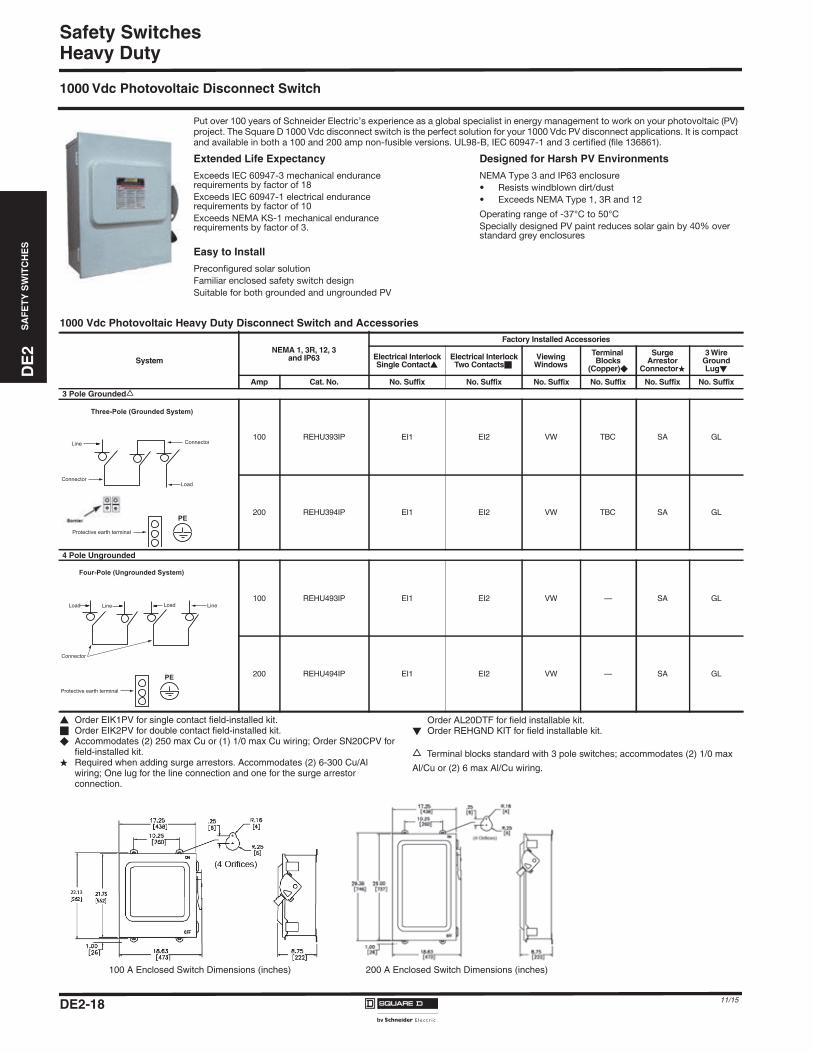
Heavy Duty
1000 Vdc Photovoltaic Disconnect Switch
� Order EIK1PV for single contact field-installed kit.� Order EIK2PV for double contact field-installed kit.� Accommodates (2) 250 max Cu or (1) 1/0 max Cu wiring; Order SN20CPV for
field-installed kit.� Required when adding surge arrestors. Accommodates (2) 6-300 Cu/Al
wiring; One lug for the line connection and one for the surge arrestorconnection.
Put over 100 years of Schneider Electric’s experience as a global specialist in energy management to work on your photovoltaic (PV) project. The Square D 1000 Vdc disconnect switch is the perfect solution for your 1000 Vdc PV disconnect applications. It is compact and available in both a 100 and 200 amp non-fusible versions. UL98-B, IEC 60947-1 and 3 certified (file 136861).
Extended Life Expectancy
Exceeds IEC 60947-3 mechanical endurance requirements by factor of 18
Exceeds IEC 60947-1 electrical endurance requirements by factor of 10
Exceeds NEMA KS-1 mechanical endurance requirements by factor of 3.
Easy to Install
Preconfigured solar solution
Familiar enclosed safety switch design
Suitable for both grounded and ungrounded PV
Designed for Harsh PV Environments
NEMA Type 3 and IP63 enclosure
• Resists windblown dirt/dust
• Exceeds NEMA Type 1, 3R and 12
Operating range of -37°C to 50°C
Specially designed PV paint reduces solar gain by 40% over standard grey enclosures
1000 Vdc Photovoltaic Heavy Duty Disconnect Switch and Accessories
SystemNEMA 1, 3R, 12, 3
and IP63
Factory Installed Accessories
Electrical InterlockSingle Contact�
Electrical InterlockTwo Contacts�
ViewingWindows
TerminalBlocks
(Copper)�
SurgeArrestor
Connector�
3 WireGroundLug�
Amp Cat. No. No. Suffix No. Suffix No. Suffix No. Suffix No. Suffix No. Suffix
3 Pole Groundeds
100 REHU393IP EI1 EI2 VW TBC SA GL
200 REHU394IP EI1 EI2 VW TBC SA GL
4 Pole Ungrounded
100 REHU493IP EI1 EI2 VW — SA GL
200 REHU494IP EI1 EI2 VW — SA GL
PE
Line
Connector
Connector
Load
Protective earth terminal
Three-Pole (Grounded System)
PE
Line
Connector
Line
Protective earth terminal
Four-Pole (Ungrounded System)
LoadLoad
100 A Enclosed Switch Dimensions (inches) 200 A Enclosed Switch Dimensions (inches)
Order AL20DTF for field installable kit.� Order REHGND KIT for field installable kit.
s Terminal blocks standard with 3 pole switches; accommodates (2) 1/0 max
Al/Cu or (2) 6 max Al/Cu wiring.
DE2_P18-20.fm Page 18 Thursday, December 10, 2015 11:26 PM
DE
2S
AF
ET
YS
WIT
CH
ES
DE2_P18-20.fm Page 19 Thursday, December 10, 2015 11:26 PM
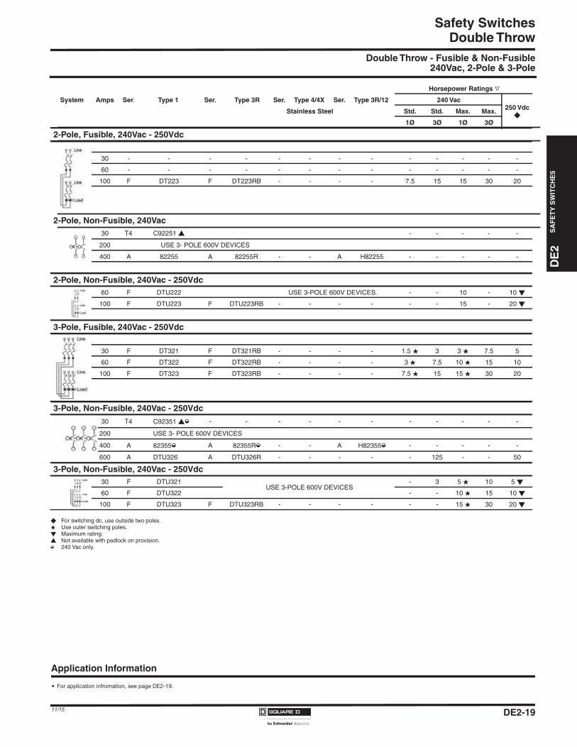
Safety SwitchesDouble Throw
Double Throw - Fusible & Non-Fusible240Vac, 2-Pole & 3-Pole
� For switching dc, use outside two poles.� Use outer switching poles.� Maximum rating.� Not available with padlock on provision.m 240 Vac only.
Type 3R/12
Horsepower Ratings r
System Amps Ser. Type 1 Ser. Type 3R Ser. Type 4/4X Ser. 240 Vac250 Vdc
�Stainless Steel Std. Std. Max. Max.
1Ø 3Ø 1Ø 3Ø
2-Pole, Fusible, 240Vac - 250Vdc
30 - - - - - - - - - - - - -
60 - - - - - - - - - - - - -
100 F DT223 F DT223RB - - - - 7.5 15 15 30 20
2-Pole, Non-Fusible, 240Vac30 T4 C92251 � - - - - -
200 USE 3- POLE 600V DEVICES
400 A 82255 A 82255R - - A H82255 - - - - -
2-Pole, Non-Fusible, 240Vac - 250Vdc60 F DTU222 USE 3-POLE 600V DEVICES. - - 10 - 10 �
100 F DTU223 F DTU223RB - - - - - - 15 - 20 �
3-Pole, Fusible, 240Vac - 250Vdc
30 F DT321 F DT321RB - - - - 1.5 � 3 3 � 7.5 5
60 F DT322 F DT322RB - - - - 3 � 7.5 10 � 15 10
100 F DT323 F DT323RB - - - - 7.5 � 15 15 � 30 20
3-Pole, Non-Fusible, 240Vac - 250Vdc30 T4 C92351 �m - - - - - - - - - - -
200 USE 3- POLE 600V DEVICES
400 A 82355m A 82355Rm - - A H82355m - - - - -
600 A DTU326 A DTU326R - - - - - 125 - - 50
3-Pole, Non-Fusible, 240Vac - 250Vdc30 F DTU321
USE 3-POLE 600V DEVICES- 3 5 � 10 5 �
60 F DTU322 - - 10 � 15 10 �
100 F DTU323 F DTU323RB - - - - - - 15 � 30 20 �
Application Information
• For application infromation, see page DE2-19.
DE2-1911/15
DE
2S
AF
ET
YS
WIT
CH
ES
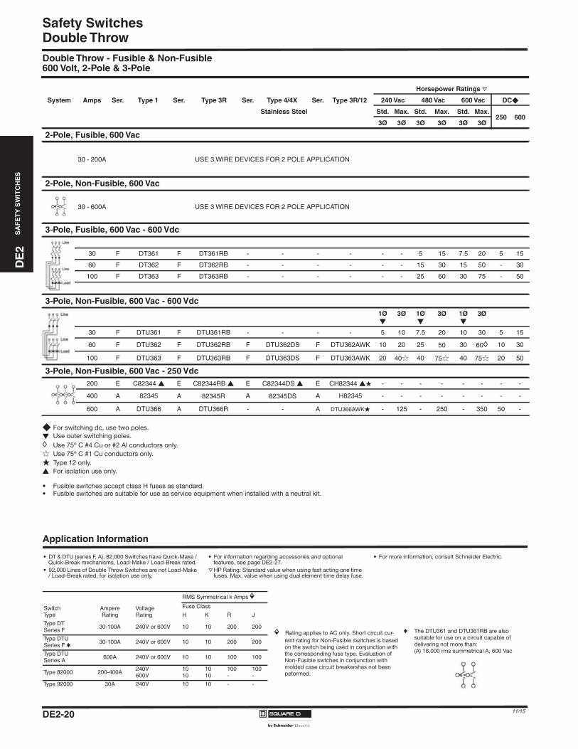
DE2_P18-20.fm Page 20 Thursday, December 10, 2015 11:26 PM
Safety SwitchesDouble ThrowDouble Throw - Fusible & Non-Fusible600 Volt, 2-Pole & 3-Pole
� For switching dc, use two poles.
� Use outer switching poles.
h Use 75º C #4 Cu or #2 Al conductors only.
� Use 75º C #1 Cu conductors only.
� Type 12 only.
� For isolation use only.
• Fusible switches accept class H fuses as standard.• Fusible switches are suitable for use as service equipment when installed with a neutral kit.
Horsepower Ratings r
System Amps Ser. Type 1 Ser. Type 3R Ser. Type 4/4X Ser. Type 3R/12 240 Vac 480 Vac 600 Vac DC�
Stainless Steel Std. Max. Std. Max. Std. Max.250 600
3Ø 3Ø 3Ø 3Ø 3Ø 3Ø
2-Pole, Fusible, 600 Vac
30 - 200A USE 3 WIRE DEVICES FOR 2 POLE APPLICATION
2-Pole, Non-Fusible, 600 Vac
30 - 600A USE 3 WIRE DEVICES FOR 2 POLE APPLICATION
3-Pole, Fusible, 600 Vac - 600 Vdc
30 F DT361 F DT361RB - - - - - - 5 15 7.5 20 5 15
60 F DT362 F DT362RB - - - - - - 15 30 15 50 - 30
100 F DT363 F DT363RB - - - - - - 25 60 30 75 - 50
3-Pole, Non-Fusible, 600 Vac - 600 Vdc1�
3Ø 1Ø�
3Ø 1Ø�
3Ø
30 F DTU361 F DTU361RB - - - - 5 10 7.5 20 10 30 5 15
60 F DTU362 F DTU362RB F DTU362DS F DTU362AWK 10 20 25 50 30 60h 10 30
100 F DTU363 F DTU363RB F DTU363DS F DTU363AWK 20 40� 40 75� 40 75� 20 50
3-Pole, Non-Fusible, 600 Vac - 250 Vdc200 E C82344 � E C82344RB � E C82344DS � E CH82344 �� - - - - - - - -
400 A 82345 A 82345R A 82345DS A H82345 - - - - - - - -
600 A DTU366 A DTU366R - - A DTU366AWK� - 125 - 250 - 350 50 -
Application Information
• DT & DTU (series F, A), 82,000 Switches have Quick-Make / Quick-Break mechanisms, Load-Make / Load-Break rated.
• 92,000 Lines of Double Throw Switches are not Load-Make / Load-Break rated, for isolation use only.
• For information regarding accessories and optional features, see page DE2-27.
r HP Rating: Standard value when using fast acting one time fuses. Max. value when using dual element time delay fuse.
• For more information, consult Schneider Electric.
RMS Symmetrical k Amps iSwitchType
AmpereRating
VoltageRating
Fuse Class
H K R J
Type DTSeries F
30-100A 240V or 600V 10 10 200 200
Type DTUSeries F �
30-100A 240V or 600V 10 10 200 200
Type DTUSeries A
600A 240V or 600V 10 10 100 100
Type 82000 200-400A240V600V
1010
1010
100-
100-
Type 92000 30A 240V 10 10 - -
i Rating applies to AC only. Short circuit cur-
rent rating for Non-Fusible switches is based
on the switch being used in conjunction with
the corresponding fuse type. Evaluation of
Non-Fusible swtches in conjunction with
molded case circuit breakershas not been
peformed.
� The DTU361 and DTU361RB are also
suitable for use on a circuit capable of
delivering not more than:
(A) 18,000 rms summetrical A, 600 Vac
DE2-20 11/15
DE2-21
DE
2S
AF
ET
YS
WIT
CH
ES
Safety Switches
11/15
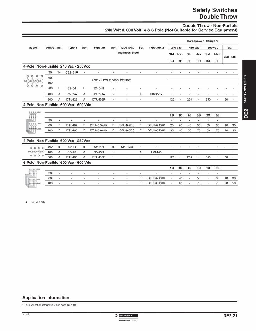
Double ThrowDouble Throw - Non-Fusible
240 Volt & 600 Volt, 4 & 6 Pole (Not Suitable for Service Equipment)
System Amps Ser. Type 1 Ser. Type 3R Type 3R/12
Horsepower Ratings r
Ser. Type 4/4X Ser. 240 Vac 480 Vac 600 Vac DC
Stainless Steel Std. Max. Std. Max. Std. Max.250 600
3Ø 3Ø 3Ø 3Ø 3Ø 3Ø
4-Pole, Non-Fusible, 240 Vac - 250Vdc
30 T4 C92451m - - - - - - - - - - - - - -
60USE 4 - POLE 600 V DEVICE
100
200 E 82454 E 82454R - - - - - - - - - - - -
400 A 82455m A 82455Rm - - A H82455m - - - - - - - -
600 A DTU426 A DTU426R - - - - 125 - 250 - 350 - 50 -
4-Pole, Non-Fusible, 600 Vac - 600 Vdc
2Ø 3Ø 2Ø 3Ø 2Ø 3Ø
30 - - - - - - - - - - - - - -
60 F DTU462 F DTU462AWK F DTU462DS F DTU462AWK 20 20 40 50 50 60 10 30
100 F DTU463 F DTU463AWK F DTU463DS F DTU463AWK 30 40 50 75 50 75 20 30
4-Pole, Non-Fusible, 600 Vac - 250Vdc
200 E 82444 E 82444R E 82444DS - - - - - - - - - -
400 A 82445 A 82445R - - A H82445 - - - - - - - -
600 A DTU466 A DTU466R - - - - 125 - 250 - 350 - 50 -
6-Pole, Non-Fusible, 600 Vac - 600 Vdc1Ø 3Ø 1Ø 3Ø 1Ø 3Ø
30 - - - - - - - - - - - - - -
60 - - - - - - F DTU662AWK - 20 - 50 - 60 10 30
100 - - - - - - F DTU663AWK - 40 - 75 - 75 20 50
Application Information
• For application information, see page DE2-19.
m - 240 Vac only
DE2_P21-31.fm Page 21 Thursday, December 10, 2015 11:28 PM
DE2-22
Safety SwitchesD
E2
SA
FE
TY
SW
ITC
HE
S
11/15
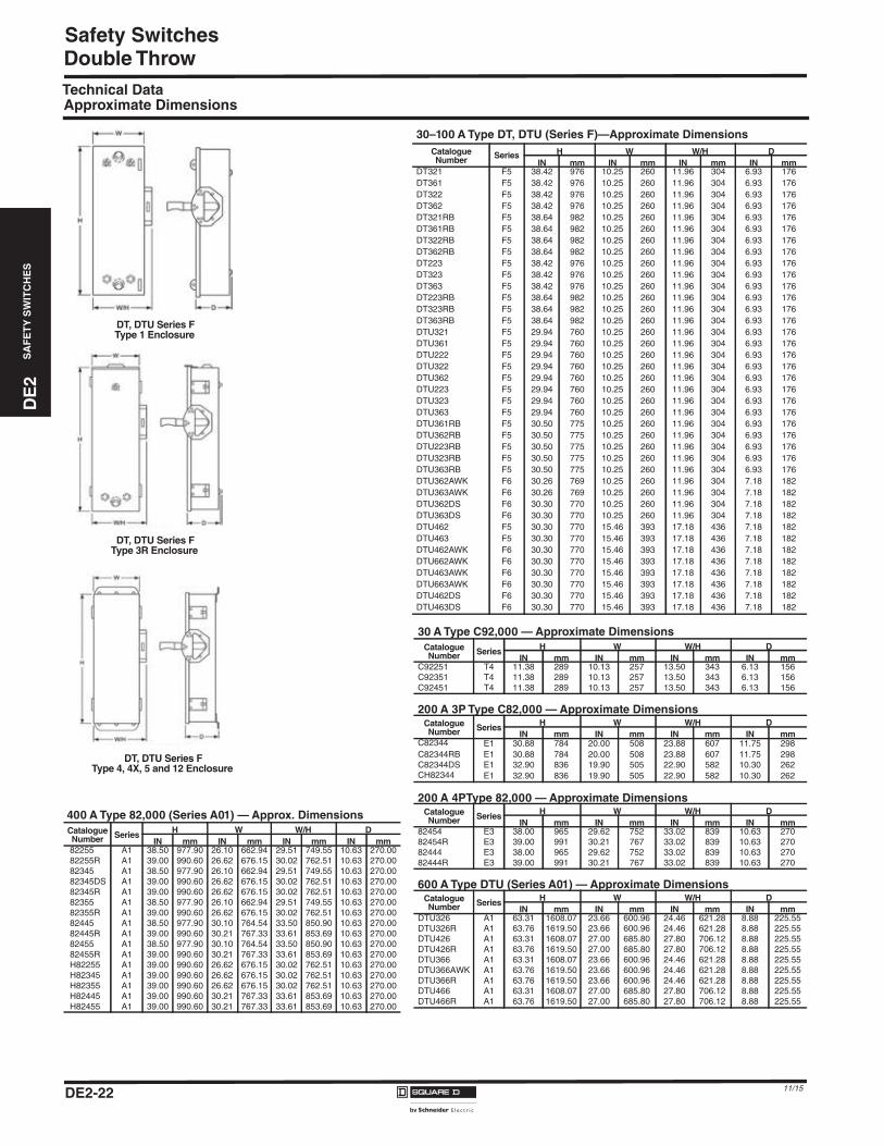
Double ThrowTechnical DataApproximate Dimensions
30–100 A Type DT, DTU (Series F)—Approximate Dimensions
CatalogueNumber Series H W W/H D
IN mm IN mm IN mm IN mmDT321 F5 38.42 976 10.25 260 11.96 304 6.93 176DT361 F5 38.42 976 10.25 260 11.96 304 6.93 176DT322 F5 38.42 976 10.25 260 11.96 304 6.93 176DT362 F5 38.42 976 10.25 260 11.96 304 6.93 176DT321RB F5 38.64 982 10.25 260 11.96 304 6.93 176DT361RB F5 38.64 982 10.25 260 11.96 304 6.93 176DT322RB F5 38.64 982 10.25 260 11.96 304 6.93 176DT362RB F5 38.64 982 10.25 260 11.96 304 6.93 176DT223 F5 38.42 976 10.25 260 11.96 304 6.93 176DT323 F5 38.42 976 10.25 260 11.96 304 6.93 176DT363 F5 38.42 976 10.25 260 11.96 304 6.93 176DT223RB F5 38.64 982 10.25 260 11.96 304 6.93 176DT323RB F5 38.64 982 10.25 260 11.96 304 6.93 176DT363RB F5 38.64 982 10.25 260 11.96 304 6.93 176DTU321 F5 29.94 760 10.25 260 11.96 304 6.93 176DTU361 F5 29.94 760 10.25 260 11.96 304 6.93 176DTU222 F5 29.94 760 10.25 260 11.96 304 6.93 176DTU322 F5 29.94 760 10.25 260 11.96 304 6.93 176DTU362 F5 29.94 760 10.25 260 11.96 304 6.93 176DTU223 F5 29.94 760 10.25 260 11.96 304 6.93 176DTU323 F5 29.94 760 10.25 260 11.96 304 6.93 176DTU363 F5 29.94 760 10.25 260 11.96 304 6.93 176DTU361RB F5 30.50 775 10.25 260 11.96 304 6.93 176DTU362RB F5 30.50 775 10.25 260 11.96 304 6.93 176DTU223RB F5 30.50 775 10.25 260 11.96 304 6.93 176DTU323RB F5 30.50 775 10.25 260 11.96 304 6.93 176DTU363RB F5 30.50 775 10.25 260 11.96 304 6.93 176DTU362AWK F6 30.26 769 10.25 260 11.96 304 7.18 182DTU363AWK F6 30.26 769 10.25 260 11.96 304 7.18 182DTU362DS F6 30.30 770 10.25 260 11.96 304 7.18 182DTU363DS F6 30.30 770 10.25 260 11.96 304 7.18 182DTU462 F5 30.30 770 15.46 393 17.18 436 7.18 182DTU463 F5 30.30 770 15.46 393 17.18 436 7.18 182DTU462AWK F6 30.30 770 15.46 393 17.18 436 7.18 182DTU662AWK F6 30.30 770 15.46 393 17.18 436 7.18 182DTU463AWK F6 30.30 770 15.46 393 17.18 436 7.18 182DTU663AWK F6 30.30 770 15.46 393 17.18 436 7.18 182DTU462DS F6 30.30 770 15.46 393 17.18 436 7.18 182DTU463DS F6 30.30 770 15.46 393 17.18 436 7.18 182
30 A Type C92,000 — Approximate Dimensions
CatalogueNumber Series H W W/H D
IN mm IN mm IN mm IN mmC92251 T4 11.38 289 10.13 257 13.50 343 6.13 156C92351 T4 11.38 289 10.13 257 13.50 343 6.13 156C92451 T4 11.38 289 10.13 257 13.50 343 6.13 156
200 A 3P Type C82,000 — Approximate DimensionsCatalogueNumber Series H W W/H D
IN mm IN mm IN mm IN mmC82344 E1 30.88 784 20.00 508 23.88 607 11.75 298C82344RB E1 30.88 784 20.00 508 23.88 607 11.75 298C82344DS E1 32.90 836 19.90 505 22.90 582 10.30 262CH82344 E1 32.90 836 19.90 505 22.90 582 10.30 262
200 A 4PType 82,000 — Approximate DimensionsCatalogueNumber Series H W W/H D
IN mm IN mm IN mm IN mm82454 E3 38.00 965 29.62 752 33.02 839 10.63 27082454R E3 39.00 991 30.21 767 33.02 839 10.63 27082444 E3 38.00 965 29.62 752 33.02 839 10.63 27082444R E3 39.00 991 30.21 767 33.02 839 10.63 270
600 A Type DTU (Series A01) — Approximate DimensionsCatalogueNumber Series H W W/H D
IN mm IN mm IN mm IN mmDTU326 A1 63.31 1608.07 23.66 600.96 24.46 621.28 8.88 225.55DTU326R A1 63.76 1619.50 23.66 600.96 24.46 621.28 8.88 225.55DTU426 A1 63.31 1608.07 27.00 685.80 27.80 706.12 8.88 225.55DTU426R A1 63.76 1619.50 27.00 685.80 27.80 706.12 8.88 225.55DTU366 A1 63.31 1608.07 23.66 600.96 24.46 621.28 8.88 225.55DTU366AWK A1 63.76 1619.50 23.66 600.96 24.46 621.28 8.88 225.55DTU366R A1 63.76 1619.50 23.66 600.96 24.46 621.28 8.88 225.55DTU466 A1 63.31 1608.07 27.00 685.80 27.80 706.12 8.88 225.55DTU466R A1 63.76 1619.50 27.00 685.80 27.80 706.12 8.88 225.55
DT, DTU Series FType 1 Enclosure
DT, DTU Series FType 3R Enclosure
DT, DTU Series FType 4, 4X, 5 and 12 Enclosure
400 A Type 82,000 (Series A01) — Approx. Dimensions
CatalogueNumber Series H W W/H D
IN mm IN mm IN mm IN mm82255 A1 38.50 977.90 26.10 662.94 29.51 749.55 10.63 270.0082255R A1 39.00 990.60 26.62 676.15 30.02 762.51 10.63 270.0082345 A1 38.50 977.90 26.10 662.94 29.51 749.55 10.63 270.0082345DS A1 39.00 990.60 26.62 676.15 30.02 762.51 10.63 270.0082345R A1 39.00 990.60 26.62 676.15 30.02 762.51 10.63 270.0082355 A1 38.50 977.90 26.10 662.94 29.51 749.55 10.63 270.0082355R A1 39.00 990.60 26.62 676.15 30.02 762.51 10.63 270.0082445 A1 38.50 977.90 30.10 764.54 33.50 850.90 10.63 270.0082445R A1 39.00 990.60 30.21 767.33 33.61 853.69 10.63 270.0082455 A1 38.50 977.90 30.10 764.54 33.50 850.90 10.63 270.0082455R A1 39.00 990.60 30.21 767.33 33.61 853.69 10.63 270.00H82255 A1 39.00 990.60 26.62 676.15 30.02 762.51 10.63 270.00H82345 A1 39.00 990.60 26.62 676.15 30.02 762.51 10.63 270.00H82355 A1 39.00 990.60 26.62 676.15 30.02 762.51 10.63 270.00H82445 A1 39.00 990.60 30.21 767.33 33.61 853.69 10.63 270.00H82455 A1 39.00 990.60 30.21 767.33 33.61 853.69 10.63 270.00
DE2_P21-31.fm Page 22 Thursday, December 10, 2015 11:28 PM
DE
2S
AF
ET
YS
WIT
CH
ES
DE2_P21-31.fm Page 23 Thursday, December 10, 2015 11:28 PM
Safety Switches
Application Information
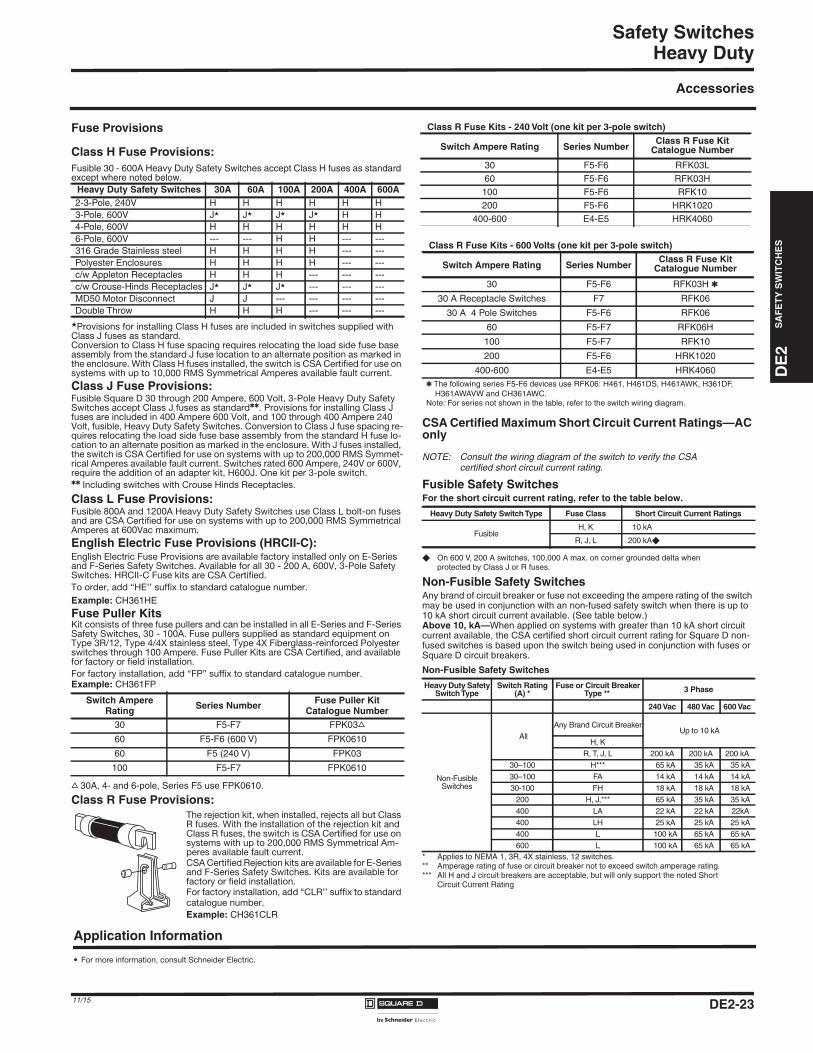
Heavy Duty
Accessories
Fuse Provisions
Class H Fuse Provisions:Fusible 30 - 600A Heavy Duty Safety Switches accept Class H fuses as standardexcept where noted below.
�Provisions for installing Class H fuses are included in switches supplied with Class J fuses as standard. Conversion to Class H fuse spacing requires relocating the load side fuse base assembly from the standard J fuse location to an alternate position as marked in the enclosure. With Class H fuses installed, the switch is CSA Certified for use on systems with up to 10,000 RMS Symmetrical Amperes available fault current.
Class J Fuse Provisions:Fusible Square D 30 through 200 Ampere, 600 Volt, 3-Pole Heavy Duty Safety Switches accept Class J fuses as standard��. Provisions for installing Class J fuses are included in 400 Ampere 600 Volt, and 100 through 400 Ampere 240 Volt, fusible, Heavy Duty Safety Switches. Conversion to Class J fuse spacing re-quires relocating the load side fuse base assembly from the standard H fuse lo-cation to an alternate position as marked in the enclosure. With J fuses installed, the switch is CSA Certified for use on systems with up to 200,000 RMS Symmet-rical Amperes available fault current. Switches rated 600 Ampere, 240V or 600V, require the addition of an adapter kit, H600J. One kit per 3-pole switch.�� Including switches with Crouse Hinds Receptacles.
Class L Fuse Provisions:Fusible 800A and 1200A Heavy Duty Safety Switches use Class L bolt-on fuses and are CSA Certified for use on systems with up to 200,000 RMS Symmetrical Amperes at 600Vac maximum.
English Electric Fuse Provisions (HRCII-C):English Electric Fuse Provisions are available factory installed only on E-Series and F-Series Safety Switches. Available for all 30 - 200 A, 600V, 3-Pole Safety Switches. HRCII-C Fuse kits are CSA Certified.
To order, add “HE’’ suffix to standard catalogue number.
Example: CH361HE
Fuse Puller KitsKit consists of three fuse pullers and can be installed in all E-Series and F-Series Safety Switches, 30 - 100A. Fuse pullers supplied as standard equipment on Type 3R/12, Type 4/4X stainless steel, Type 4X Fiberglass-reinforced Polyester switches through 100 Ampere. Fuse Puller Kits are CSA Certified, and available for factory or field installation.
For factory installation, add “FP” suffix to standard catalogue number.Example: CH361FP
s 30A, 4- and 6-pole, Series F5 use FPK0610.
Class R Fuse Provisions:The rejection kit, when installed, rejects all but Class R fuses. With the installation of the rejection kit and Class R fuses, the switch is CSA Certified for use on systems with up to 200,000 RMS Symmetrical Am-peres available fault current. CSA Certified Rejection kits are available for E-Series and F-Series Safety Switches. Kits are available for factory or field installation.For factory installation, add “CLR’’ suffix to standard catalogue number.
Example: CH361CLR
CSA Certified Maximum Short Circuit Current Ratings—AConly
NOTE: Consult the wiring diagram of the switch to verify the CSAcertified short circuit current rating.
� On 600 V, 200 A switches, 100,000 A max. on corner grounded delta whenprotected by Class J or R fuses.
Non-Fusible Safety SwitchesAny brand of circuit breaker or fuse not exceeding the ampere rating of the switchmay be used in conjunction with an non-fused safety switch when there is up to10 kA short circuit current available. (See table below.)Above 10, kA—When applied on systems with greater than 10 kA short circuitcurrent available, the CSA certified short circuit current rating for Square D non-fused switches is based upon the switch being used in conjunction with fuses orSquare D circuit breakers.
Heavy Duty Safety Switches 30A 60A 100A 200A 400A 600A2-3-Pole, 240V H H H H H H3-Pole, 600V J� J� J� J� H H4-Pole, 600V H H H H H H6-Pole, 600V --- --- H H --- ---316 Grade Stainless steel H H H H --- ---Polyester Enclosures H H H H --- ---c/w Appleton Receptacles H H H --- --- ---c/w Crouse-Hinds Receptacles J� J� J� --- --- ---MD50 Motor Disconnect J J --- --- --- ---Double Throw H H H --- --- ---
Switch AmpereRating Series Number Fuse Puller Kit
Catalogue Number30 F5-F7 FPK03s
60 F5-F6 (600 V) FPK0610
60 F5 (240 V) FPK03
100 F5-F7 FPK0610
Class R Fuse Kits - 600 Volts (one kit per 3-pole switch)
Switch Ampere Rating Series NumberClass R Fuse Kit
Catalogue Number
30 F5-F6 RFK03H �
30 A Receptacle Switches F7 RFK06
30 A 4 Pole Switches F5-F6 RFK06
60 F5-F7 RFK06H
100 F5-F7 RFK10
200 F5-F6 HRK1020
400-600 E4-E5 HRK4060� The following series F5-F6 devices use RFK06: H461, H461DS, H461AWK, H361DF,
H361AWAVW and CH361AWC.Note: For series not shown in the table, refer to the switch wiring diagram.
Fusible Safety SwitchesFor the short circuit current rating, refer to the table below.
Heavy Duty Safety SwitchType Fuse Class Short Circuit Current Ratings
FusibleH, K 10 kA
R, J, L 200 kA�
Non-Fusible Safety Switches
Heavy Duty SafetySwitchType
Switch Rating(A) *
Fuse or Circuit BreakerType ** 3 Phase
240 Vac 480 Vac 600 Vac
Non-FusibleSwitches
AllAny Brand Circuit Breaker
Up to 10 kAH, K
R, T, J, L 200 kA 200 kA 200 kA30–100 H*** 65 kA 35 kA 35 kA30–100 FA 14 kA 14 kA 14 kA30-100 FH 18 kA 18 kA 18 kA
200 H, J,*** 65 kA 35 kA 35 kA400 LA 22 kA 22 kA 22kA400 LH 25 kA 25 kA 25 kA400 L 100 kA 65 kA 65 kA600 L 100 kA 65 kA 65 kA
* Applies to NEMA 1, 3R, 4X stainless, 12 switches.** Amperage rating of fuse or circuit breaker not to exceed switch amperage rating.*** All H and J circuit breakers are acceptable, but will only support the noted Short
Circuit Current Rating
Class R Fuse Kits - 240 Volt (one kit per 3-pole switch)
Switch Ampere Rating Series NumberClass R Fuse Kit
Catalogue Number
30 F5-F6 RFK03L60 F5-F6 RFK03H
100 F5-F6 RFK10200 F5-F6 HRK1020
400-600 E4-E5 HRK4060
DE2-2311/15
• For more information, consult Schneider Electric.
DE
2S
AF
ET
YS
WIT
CH
ES
DE2_P21-31.fm Page 24 Thursday, December 10, 2015 11:28 PM
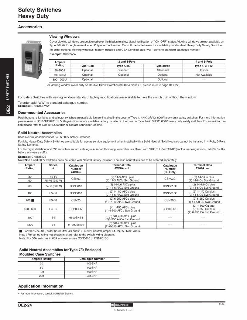
Safety SwitchesHeavy Duty
Accessories
For Safety Switches with viewing windows standard, factory modifications are available to have the switch built without the window.
To order, add “WW” to standard catalogue number. Example: CH361DSWW
Door-mounted AccessoriesPush buttons, pilot lights and selector switches are available factory installed in the cover of Type 1, 4/4X, 3R/12, 600V heavy duty safety switches. For more informationplease refer to D3110HO0701BP. Voltage indicators are available factory installed in the cover of Type 4/4X, 3R/12, 600V heavy duty safety switches. For more informa-tion please refer to D3110HO0601BP or contact Schneider Electric.
Solid Neutral AssembliesSolid Neutral Assemblies for 240 & 600V Safety Switches
Fusible, Heavy Duty Safety Switches are suitable for use as service equipment when installed with a Solid Neutral. Solid Neutrals cannot be installed in 4-Pole, 6-Pole Safety Switches.
For factory installation, add “N” suffix to standard catalogue number. If catalogue number is suffixed with “RB”, “DS” or “AWK” (enclosure designations), add “N” suffix before enclosure suffix.
Example: CH361NDSNote:Non fused 600V switches does not come with Neutral factory installed. The solid neutral kits has to be ordered separately.
Viewing WindowsCover viewing windows are positioned over the blades to allow visual verification of “ON-OFF’’ status. Viewing windows are not available on
Type 7/9, 4X Fiberglass-reinforced Polyester Enclosures. Consult the table below for availability on standard Heavy Duty Safety Switches.
To order optional viewing windows, factory installed and CSA Certified, add “VW’’ suffix to standard catalogue number.
Example: CH365VW
AmpereRating
2 and 3-Pole 4 and 6-Pole
Type 1, 3R Type 4/4X Type 3R/12 Type 1, 3R/12
30-200A Optional Standard Standard Optional
400-600A Optional Optional Optional Not Available
800-1200 A Optional ---- Optional ----
AmpereRating
Series#
CatalogueNumber(AI/Cu)
Terminal DataAWG/kcmil
CatalogueNumber
(Cu Only)
Terminal DataAWG/kcmil
30 F5-F6CSN03 (2) 14-3 Al/Cu plus
(1) 14-3 Al/Cu Svc Ground CSN03C (2) 14-6 Cu plus(1) 14-6 Cu Svc Ground60 F5-F6 (240 V)
60 F5-F6 (600 V) CSN0610 (2) 14-1/0 Al/Cu plus(2) 14-6 Al/Cu Svc Ground CSN0610C (2) 14-1/0 Cu plus
(2) 14-6 Cu Svc Ground
100 F5-F6 CSN0610 (2)14-1/0 Al/Cu plus(2) 14-6 Al/Cu Svc Ground CSN0610C (2)14-1/0 Cu plus
(2) 14-6 Cu Svc Ground
200 � F5-F6 CSN20 (2) 6-250 Al/Cu plus(1) 14-10 Al/Cu Svc Ground CSN20C (2) 6-250 Cu plus
(1) 14-1/0 Cu Svc Ground
400 - 600 E4-E5 CH600SN (4) 1-750 Al/Cu plus(1) 4-300 Al/Cu Svc Ground CH600SNC
(2) 1-600 Cu and(2) 4-350 Cu plus
(2) 6-250 Cu Svc Ground
800 E4 H800SNE4 (6) 3/0-750 Al/Cu plus(2)6-350 Al/Cu Svc Ground ---- ----
1200 E4 H1200SNE4 (8) 3/0-750 Al/Cu plus(2) 6-350 Al/Cu Svc Ground ---- ----
� For 200% neutral, order (2) neutral kits and (1) SN20NI neutral jumper kit. (2) 350 Max. Al/Cu.Note : For series rating not shown in chart refer to the switch wiring diagram.Note: For 30A switches in 60A enclosures use CSN0610 or CSN0610C
Solid Neutral Assemblies for Type 7/9 EnclosedMoulded Case Switches
Ampere Rating Catalogue Number
30 100SNA
60 100SNA100 100SNA200 225SNA
Application Information
• For more information, consult Schneider Electric.
For viewing window availability on Double Throw Switches 30-100A Series F, please refer to page DE2-27.
DE2-24 11/15
DE
2S
AF
ET
YS
WIT
CH
ES
DE2_P21-31.fm Page 25 Thursday, December 10, 2015 11:28 PM
Safety SwitchesHeavy Duty
Accessories
Electrical Auxillary Interlock KitsElectrical interlocks for Heavy Duty 30-1200 Ampere Safety Switches are avail-able factory installed or in kit form for field installation. Each kit contains instruc-tions for proper field mounting. A pivot arm operates from switch mechanism, breaking the control circuit before the main switch blades break. Electrical inter-lock kits are CSA Certified.
For factory installation add “EI” or “EI2” suffix to standard catalogue number.
Example: CH361EI
• Electrical interlock kit catalogue numbers with -1 suffix indicates one normally open and one normally closed contact; -2 indicates two normally open and two normally closed contacts.
• Not suitable for Elevator use.� HU461AWK uses EK306-1,2; H461, H461 DS, H461AWK, HU461,
HU461DS, HU661DS, HU661AWK, H361AWAVW, CH361AWC,CHU361AWA, CHU361AWC use EIK-1,2.
� Safety switches complete with voltage monitors use EIK1 or EIK2.
� Single pole throw interlock kits are rated 1/2 HP @ 110 and 220Vac.• -1 Suffix utilizes a 9007A01 limit switch.• -2 Suffix utilizes a 9007C03 limit switch.
Elevator Rated Electrical Interlocks*These interlocks are CSA approved, field installable and can be used in switches with date codes starting with 06454 (year 2006, week 45, day 4 of week) or later.
* CSA approved for Type 1, 3R, 4/4X & 3R/12 applications
Key Interlock SystemsFactory installed only on Heavy Duty Safety Switches and Double Throw Safety Switches.
Interlocks are used to prevent the authorized op-erator from making an unauthorized operation. Not available on hazardous location devices (Type 7/9) or fibreglass reinforced polyester (Type 4X).
The Key Interlock System is a simple and easy method of applying individual key interlock units and assemblies to the above equipment so as to require operation in a predetermined sequence.
Quoting: Contact Schneider Electric for catalog number, availability, and pricing prior to quoting a job. Detailed information is re-quired before an order can be processed.
Before preparation of construction equipment with key interlocks can begin, the following information must be known:
1. Ultimate user –name and address
2. Key number, ‘SO’ number and item number from lock assemblies on any existing locks to be interlocked with.
3. Sketch of sequence of operations to be accomplished and name and phone number of specifying engineer. Confirmation from customer is required before an order is released for production.
4. Other Square D equipment interlocked – order point, order numbers, etc. for coordination.
5. Schneider Electric key interlocks will be furnished unless otherwise specified.
To order, add “KI”, “KI2” or “KIKI” suffix to standard catalogue number. Contact your local Schneider Electric office for a reference number prior to entering the order.
Example: CH364KIKI = 1 lock per switchKI2 = 1 lock with 2 cylinders per switchKIKI = 2 separate locks per switch
Lock-On ProvisionsProvision for one 3/8 inch hasp padlock is available factory installed on Types 1, 3R, 4/4X stainless steel and 3R/12 switches. This modification will allow the switch to be locked in the “ON’’ position.
To order, add “SPLO” suffix to standard catalogue number.
Example: CH361SPLO
Lock-Off GuardDesigned for use with safety switches in commercial and industrial settings, Lock-Off Guard enhances the reliability of lockout procedures to isolate power in daily activities and provide an effective way to interrupt power in an emergency.The innovative Lock-Off Guard works by covering the lockout/tag-out opening whenever the switch is in the “ON” position, preventing a padlock from being inadvertently inserted into the switch lockplate.
This device is designed to help prevent accidents caused by an untrained or distracted employee, who could inadvertently attempt to apply a lockout device to a switch without turning the switch to “OFF.”- Installs on Square D 30A to 200A F series Type 1, 3R and 12 switches in less than 30 seconds.- Bright red colour reminds users of the seriousness of lockout/tag-out procedures.
60A 600V and 100A 240V or 600V switches prior to series F05 require the handle and mechanism be upgraded in order to install the kits.These kits are marked cURus for field or factory installation.
Field Installation KitsAmpere rating Catalogue number30A LOGK160A 240V LOGK160A 600V LOGK2100A and 200A LOGK2
Factory Installed option is availableOrder using “LOG” suffix on standard switch catalogue numbers.
Electrical Interlock Kit �
Ampere Rating Series Catalogue Number
30 F5-F6 EIK031 or EIK032 �60
(600 V) F5-F6 EIK1 or EIK2 �
60(240 V) F5-F6 EIK031 or EIK032 �
100-200 F5-F6 EIK1 or EIK230-100
Receptacle Switches F5-F7 EIK1 or EIK2
30-2004 and 6 Pole Switches F5-F6 EIK1 or EIK2
400-1200 E4-E5 EIK40601 or EIK40602
� Electrical Interlock Kit(Type 4X Fiberglass-reinforced Polyester Enclosure)
AmpereRating
Catalogue Number(1NO/1NC)
Catalogue Number(2NO/2NC)
30A(F-Series) 9999TC10 9999TC20
60A(F-Series) 9999TC10 9999TC20
100A(F-Series) 9999TC10 9999TC20
200A 9999R8 9999R9
Electrical Interlock Contact Ratings �
InterlockType
AC - 50 or 60 Hz DC
Volts Make Break Cont. Volts Make &Break Cont.
1 NO/1 NCCONTACT(-1 Suffix)
120 40A 15A 15A 115 .50A 15A240 20A 10A 15A 230 .25A 15A480 10A 6A 15A - - -600 8A 5A 15A 600 .05A 15A
2 NO/2 NCCONTACTS(-2 Suffix)
120 30A 3.0A 10A 115 1.0A 10A240 15A 1.5A 10A 230 .30A 10A480 7.5A .75A 10A - - -600 6.0A .60A 10A 600 .10A 10A
AmpereRating
Type 1,240VAC
ElevatorInterlock
Type 1,600VAC
ElevatorInterlock
30 CH321N EIK031EV CH361 EIK031EV60 CH322N EIK031EV CH362 EIK06101EV
100 CH323N EIK06101EV CH363 EIK06101EV200 CH324N EIK201EV CH364 EIK201EV
Application Information
• For more information, consult Schneider Electric.
DE2-2511/15
DE
2S
AF
ET
YS
WIT
CH
ES
DE2_P21-31.fm Page 26 Thursday, December 10, 2015 11:28 PM
Safety SwitchesHeavy Duty
Accessories
Rainproof Bolt-On Hubs —
For Use On Type 3R Enclosures
Watertight Hubs —
For Use On Type 4/4X Stainless Steel and Type 3R/12 Enclosures
Note: Gaskets are provided.
� Two required if grounding conductors are run in parallel.* Optional Copper equipment grounding kit for the 4and 6 Pole 30A F series : H461DS, H461AWK, HU461DS, HU661DS and HU661AWK accepts GTK03C and
HU461AWK accepts GTK0610C.
Note: For equipment grounding kits for the 30A switches inside 60A enclosures please refer to the switch wiring diagram.
ConduitSize
3/4 1 1 1/4 1 1/2 2 2 1/2 3 3 1/2 4 ClosingCap
RainproofHub Cat. No. B075 B100 B125 B150 B200 B250 B300 B350 B400 BCAP
• Type 3R rainproof enclosures have a bolt-on closing cap factory installed. Order bolt-on hubs separately from table above. Hubs thru size 2 1/2 can be directly installed on RB devices. Devices requiring 3" or larger hubs must have holes cut in the field. Gaskets are provided on 3" and larger hubs.
• All hubs are CSA Certified for indoor and rainproof applications.
Conduit Trade Size 1/2 3/4 1 1 1/4 1 1/2 2 2 1/2 3 3 1/2 4
Standard-ZincHub Catalogue Number H050 H075 H100 H125 H150 H200 H250 H300 H350 H400
Chrome PlatedHub Catalogue Number H050CP H075CP H100CP H125CP H150CP H200CP
AmpereRating Series Catalogue Number
(AI/Cu)Terminal Data
AWG/kcmilCatalogue Number
(Cu Only)Terminal Data
AWG/kcmil
30 F5-F6GTK03 (2) 14-4 Cu or (2) 12-4 Al or
(4) 14-12 Cu or (4) 12-10 Al GTK03C * (2) 14-6 Cu
60F5-F6 (240 V)
F5-F6 (600 V)GTK0610 (2) 14-1/0 Cu or (2) 12-1/0 Al and
(2) 14-6 Cu or (2) 12-6 Al GTK0610C (2) 14-1/0 Cu and(2) 14-6 Cu100 F5-F6
200 F5-F6 PKOGTA2 (2) 10-2/0 Cu or (2) 6-2/0 Al PKOGTC2 (2)-14-4 Cu
400-600 E4-E5PKOGTA2
(2 Required) �(2) 10-2/0 Cu or
(2) 6-2/0 Al PKOGTC3 (4) 14-1/0 Cu
800 E4 PKOGTA7 (4) 4-350 Al/Cu ---- ----
1200 E4 PKOGTA8 (8) 4-350 Al/Cu ---- ----
Terminal Lug Data �
AmpereRating
ConductorsPer Phase
Type 1, 3R, 4/4X & 3R/12Wire Range AWG/Kcmil
Type 7/9Wire Range AWG/Kcmil
30 � 1 12-2 (Al) or 14-2 (Cu)
60 1 12-2 (Al) or 14-2 (Cu) Use 75 'c copper wire only. #6 AWG Copper wirerequired for 60A rating
100 1 12 - 1/0 (Al) or 14 - 1/0 (Cu) Use 75' C copper wire only. #3 AWG copper wirerequired for 100A rating.
200 1 6 - 300 (Al/Cu)Use 75' C copper wire only. Lug wire range is #3AWG-350 kcmil. not UL/CSA listed due to inade-
quate wire bending space.
400 1 or 2 1/0 - 750 (Al/Cu)� or 1/0 - 300 (Al/Cu)
600 2 3/0 - 500 (Al/Cu)
800 3 3/0 - 750 (Al/Cu)
1200 4 3/0 - 750 (Al/Cu)
Application Information
• For more information, consult Schneider Electric.
“RB Hub”
� 30-100 Amp switches suitable for 60°C or 75°C conductors. 200-1200 Amp switch suitable for 75°C conductors.� Option sized lugs not available.� HU461AWK - #14 - 6 AWG (Cu).� Max. wire range (1) 600 kcmil or (2) 300 kcmil Al/Cu on Type 4/4X Stainless and Type 12.
Equipment Grounding KitsCanadian Safety Switches come complete with factory installed Grounding Kits. Additional Grounding Kits are available for field or factory installation in 30-1200 Am-
pere, 240 & 600 Volt Heavy Duty Switches.
For factory installation, add “GL” suffix to standard catalogue number.
Example: CH361GL
DE2-26 11/15
DE
2S
AF
ET
YS
WIT
CH
ES
DE2_P21-31.fm Page 27 Thursday, December 10, 2015 11:28 PM
Safety SwitchesHeavy Duty
Accessories
Copper Lugs
Note: One kit includes all phase line/load lugs for a 3-pole switch.CL0306F, CL10F and CL20F includes six lugs.CL40F and CL60F includes 12 lugs
Double Lug Kits200 A heavy duty F-series switches are supplied standard with lugs suitable for one wire per phase. For two wires per phase and neutral, order the Double Lug Kit.
Not listed on switch’s wiring diagram as an accessory.
Compression Lug Kits (800 and 1200A)Compression lug kits are available for field and factory installation. Each kit con-sists of VCEL-075-12H1 VERSA- CRIMP compression Lugs and lug landing con-nectors capable of converting line and loadside of one switch pole or neutral.
CSA certified.
Order one field - installable kit per pole or neutral.
Example: 3-pole, 3 wire requires 3 kits; 3-pole, 4 wire requires 4 kits.
For factory installation, add “LK” suffix to standard catalogue number.Example: CH367LK
Switch LubricantCatalogue Number SWLUB is a field maintenance lubricant for servicing blade/jaw components in safety switches, 600V and below. SWLUB consists of one 5.3 ounce of BJ20 High Performance Synthetic Grease by Dow Corning®, which has an operating temperature range from -45° to 180° Celsius.
Square D Grey Touch-up Paint
Phenolic Legend PlatesAvailable engraved and mounted on all Heavy Duty Safety Switches except Type 7/9. Legend engraved in 1/4 inch high white letters on black background. Cus-tomer must provide legend.
To order, add “NP” suffix to standard catalogue number.
Example: CH361NP(Pump)
Special PaintCSA Certified Heavy Duty Switches are available painted with special safety co-lours. Special colours available are safety red, safety orange, safety yellow, safety green, safety blue, radiant purple, black and white. The special epoxy chemical resistant finish paint is applied over our standard grey finish.
Not available on NEMA 4X Fiberglass, NEMA 4/4X/5 Stainless steel nor NEMA 7 and 9.
A minimum quantity of 10 is required.Order by description.Example: CH361SP
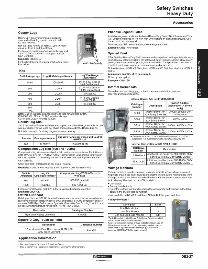
Internal Barrier KitsThese barriers provide added protection when a switch door is open.cUL recognized components.
Voltage MonitorsVoltage monitors installed on safety switches indicate when voltage is present,helping to prevent arc-flash hazards and electric shocks during maintenance work.Voltage monitors can be combined with other safety features such as Key Inter-lock, Viewing Windows or Lock-ON provisions• CSA Listed• Factory installed only• Order the voltage monitors by adding the appropriate suffix shown in the table
below to the switch catalog number• Not available on NEMA 7 and 9 and NEMA 4X Fiberglass switches.
Voltage Monitors *
Heavy Duty safety switches are supplied standard with Al lugs, which accept both Cu and Al wires.
Not available for use on NEMA Type 4X Fiber-glass, or Type 7 and 9 switches.
For factory installation of copper only lugs add “SLC” suffix to standard catalogue number.CSA Certified.
Example: CH361SLCFor field installation of copper only lug kits, order kits below.
Kits
Switch Amperage Lug Kit Catalogue Number Lug Wire RangeAWG/kcmil
30-60 CL0306F (1) 14-8 Cu Solid or14-4 Cu Standard
100 CL10F (1) 14-8 Cu solid or14-1/0 Cu standard
200 CL20F (1) 6-250 Cu
400 CL40F (1) 1-600 Cu plus(1) 6-250 Cu
600 CL60F (1) 4-350 Cu
800 – –
1200 – –
Ampere Catalogue Number Lug Wire Range per Phase and NeutralAWG/ kcmil
200 AL20DTF (2) 6-300 Cu/Al
SwitchAmperage
Lug KitCatalogue Number
Compression Lug(VCEL-075-12H1)Wire Size
800 H8LKE2 500-750 Kcmil(Al)or
500 Kcmil(Cu)1200 H12LKE2
Description Catalogue Number
Field Maintenance Lubricant SWLUB
Description Catalogue Number
12 oz. Aerosol Paint Can, Square D ANSI-49Gray Touch-Up Paint PK49SP
Internal Barrier Kits for 30-200A HDSS
CatalogueNumber Description
Switch AmpereApplication (F Series
only)
SS03 Interior Barrier for30A Safety Switch�
240Vac, 600Vac–30A240Vac–60A
SS06 Interior Barrier for60A Safety Switch 600Vac–60A
SS10 Interior Barrier for100A Safety Switch 240Vac, 600Vac–100A
SS20 Interior Barrier for200A Safety Switch 240Vac, 600Vac–200A
� Requires arc shield on 240V switches be changed to 600V arcsuppressor. Arc suppressor must be purchased separately.
Internal Barrier Kits for 800-1200A HDSS
CatalogueNumber Description
SS80120LI Additional line barrier for 800-1200A, 600VSeries E04 Heavy Duty Safety Switch
SS80120LO Additional load barrier for 800-1200A, 600VSeries E04 Heavy Duty Safety Switch
Description SuffixLine Side Monitor SILoad Side Monitor LI
Line and Load Side Monitor LI2*Available on 30-1200 A Heavy Duty Safety Switches and 30-400 A Double Throw Safety SwitchesNote: For switches 60 amps or less, indicators require use of100A size enclosure. Add “3” to the catalog number prior tosecond set of alphabetical characters (e.g., CH361AWKbecomes CH3613AWKLI for load indicator).
Application Information
• For more information, consult Schneider Electric.
• Dow Coming® is a Registered Trademark of Dow Corning Corporation.
Al/Cu To Cu only
DE2-2711/15
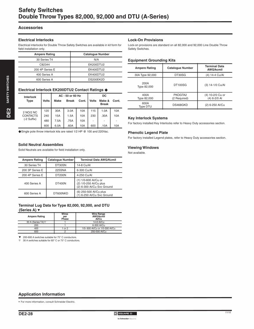
DE
2S
AF
ET
YS
WIT
CH
ES
DE2_P21-31.fm Page 28 Thursday, December 10, 2015 11:28 PM
Safety SwitchesDouble Throw Types 82,000, 92,000 and DTU (A-Series)
Accessories
Electrical InterlocksElectrical interlocks for Double Throw Safety Switches are available in kit form forfield installation only.
Electrical Interlock EK200DTU2 Contact Ratings �
�Single pole throw interlock kits are rated 1/2 HP @ 100 and 220Vac.
Solid Neutral AssembliesSolid Neutrals are available for field installation only.
p 200-600 A switches suitable for 75° C conductors.
r 30 A switches suitable for 60° C or 75° C conductors.
Lock-On ProvisionsLock-on provisions are standard on all 82,000 and 92,000 Line Double ThrowSafety Switches.
Equipment Grounding Kits
Key Interlock SystemsFor factory installed Key Interlocks refer to Heavy Duty accessories section.
Phenolic Legend PlateFor factory installed Legend plates, refer to Heavy Duty accessories section.
Viewing WindowsNot available.
Ampere Rating Catalogue Number
30 Series T4 N/A
C82344 EK200DTU2
200 4P Series E EK400DTU2
400 Series A EK400DTU2
600 Series A DS200EK2D
InterlockType
AC - 50 or 60 Hz DC
Volts Make Break Cont. Volts Make &Break
Cont.
2 NO/2 NCCONTACTS(-2 Suffix)
120 30A 3.0A 10A 115 1.0A 10A
240 15A 1.5A 10A 230 .30A 10A
480 7.5A .75A 10A - - -
600 6.0A .60A 10A 600 .10A 10A
Ampere Rating Catalogue Number Terminal Data AWG/Kcmil
30 Series T4 DT30SN 14-8 Cu/Al
200 3P Series E 225SNA 6-300 Cu/Al
200 4P Series E DT200N 4-250 Cu/Al
400 Series A DT400N(1) 1/0-600 Al/Cu or(2) 1/0-250 Al/Cu plus(2) 6-300 Al/Cu Svc Ground
600 Series A DT600NKD (6) 250-500 Al/Cu plus(1) 6-250 Al/Cu Svc Ground
Ampere Rating Catalogue Number Terminal DataAWG/kcmil
30A Type 92,000 DT30SG (4) 14-4 Cu/Al
200AType 82,000 DT100SG (3) 14-1/0 Cu/Al
400AType 82,000
PKOGTA2(2 Required)
(4) 10-2/0 Cu or(4) 6-2/0 Al
600AType DTU DS468GKD (2) 6-250 Al/Cu
Application Information
• For more information, consult Schneider Electric.
Terminal Lug Data for Type 82,000, 92,000, and DTU(Series A) p
Ampere RatingWires
perPhase
Wire RangeAWG/kcmil
Al/Cu30 A (Series T4) r 1 14-8 Al/Cu
200 1 6-300 Al/Cu400 1 or 2 1/0- 600 Al/Cu or 1/0-300 Al/Cu600 2 250-500 Al/Cu
DE2-28 11/15
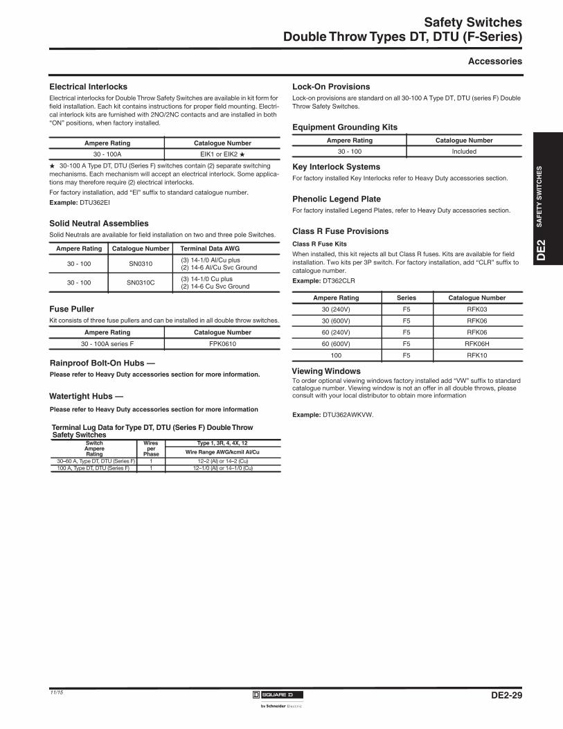
DE
2S
AF
ET
YS
WIT
CH
ES
DE2_P21-31.fm Page 29 Thursday, December 10, 2015 11:28 PM
Safety SwitchesDouble Throw Types DT, DTU (F-Series)
Accessories
Electrical InterlocksElectrical interlocks for Double Throw Safety Switches are available in kit form for
field installation. Each kit contains instructions for proper field mounting. Electri-
cal interlock kits are furnished with 2NO/2NC contacts and are installed in both
“ON” positions, when factory installed.
� 30-100 A Type DT, DTU (Series F) switches contain (2) separate switching
mechanisms. Each mechanism will accept an electrical interlock. Some applica-
tions may therefore require (2) electrical interlocks.
For factory installation, add “EI” suffix to standard catalogue number.
Example: DTU362EI
Solid Neutral AssembliesSolid Neutrals are available for field installation on two and three pole Switches.
Fuse PullerKit consists of three fuse pullers and can be installed in all double throw switches.
Lock-On ProvisionsLock-on provisions are standard on all 30-100 A Type DT, DTU (series F) DoubleThrow Safety Switches.
Equipment Grounding Kits
Key Interlock SystemsFor factory installed Key Interlocks refer to Heavy Duty accessories section.
Phenolic Legend PlateFor factory installed Legend Plates, refer to Heavy Duty accessories section.
Class R Fuse Provisions
Viewing WindowsTo order optional viewing windows factory installed add “VW” suffix to standard catalogue number. Viewing window is not an offer in all double throws, please consult with your local distributor to obtain more information
Example: DTU362AWKVW.
Ampere Rating Catalogue Number
30 - 100A EIK1 or EIK2 �
Ampere Rating Catalogue Number Terminal Data AWG
30 - 100 SN0310 (3) 14-1/0 Al/Cu plus(2) 14-6 Al/Cu Svc Ground
30 - 100 SN0310C (3) 14-1/0 Cu plus(2) 14-6 Cu Svc Ground
Ampere Rating Catalogue Number
30 - 100A series F FPK0610
Ampere Rating Catalogue Number
30 - 100 Included
Class R Fuse Kits
When installed, this kit rejects all but Class R fuses. Kits are available for field
installation. Two kits per 3P switch. For factory installation, add “CLR” suffix to
catalogue number.
Example: DT362CLR
Ampere Rating Series Catalogue Number
30 (240V) F5 RFK03
30 (600V) F5 RFK06
60 (240V) F5 RFK06
60 (600V) F5 RFK06H
100 F5 RFK10Rainproof Bolt-On Hubs —
Please refer to Heavy Duty accessories section for more information.
Watertight Hubs —
Please refer to Heavy Duty accessories section for more information
Terminal Lug Data forType DT, DTU (Series F) DoubleThrowSafety Switches
SwitchAmpereRating
Wiresper
Phase
Type 1, 3R, 4, 4X, 12
Wire Range AWG/kcmil Al/Cu
30–60 A, Type DT, DTU (Series F) 1 12–2 (Al) or 14–2 (Cu)
100 A, Type DT, DTU (Series F) 1 12–1/0 (Al) or 14–1/0 (Cu)
DE2-2911/15
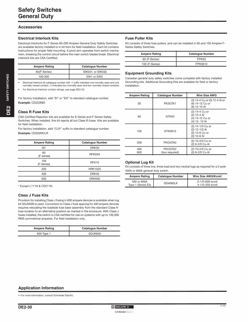
DE
2S
AF
ET
YS
WIT
CH
ES
DE2_P21-31.fm Page 30 Thursday, December 10, 2015 11:28 PM
Safety SwitchesGeneral Duty
Accessories
Electrical Interlock KitsElectrical interlocks for F-Series 60-200 Ampere General Duty Safety Switches
are available factory installed or in kit form for field installation. Each kit contains
instructions for proper field mounting. A pivot arm operates from switch mecha-
nism, breaking the control circuit before the main switch blades break. Electrical
interlock kits are CSA Certified.
• Electrical interlock kit catalogue number with -1 suffix indicates one normally open and one
normally closed contact; -2 indicates two normally open and two normally closed contacts.
• For Electrical Interlock contact ratings, see page DE2-23.
For factory Installation, add “EI” or “EI2” to standard catalogue number.
Example: CD223NEI
Class R Fuse KitsCSA Certified Rejection kits are available for E-Series and F-Series Safety
Switches. When installed, this kit rejects all but Class R fuses. Kits are available
for field installation.
For factory installation, add “CLR’’ suffix to standard catalogue number.
Example: CD222NCLR
* Except L111N & CD211N
Class J Fuse KitsProvision for installing Class J fusing in 600 ampere devices is available when lug
kit GDJK600 is used. Conversion to Class J fuse spacing for 400 ampere devices
requires relocating the loadside fuse base assembly from the standard Class H
fuse location to an alternative position as marked in the enclosure. With Class J
fuses installed, the switch is CSA certified for use on systems with up to 100,000
RMS symmetrical amperes. For field installation only.
Fuse Puller KitsKit consists of three fuse pullers, and can be installed in 60 and 100 Ampere F-
Series Safety Switches.
Equipment Grounding KitsCanadian general duty safety switches come complete with factory installed
Grounding kits. Additional Grounding Kits are available for field or factory
installation.
Optional Lug KitKit consists of three line, three load and two neutral lugs as required for a 3-pole
400A or 600A general duty switch.
Ampere Rating Catalogue Number
60(F-Series) ElK031, or ElK032
100-200 EIK1 or EIK2
Ampere Rating Catalogue Number
30* DRK30
60 (F-series)
RFK03H
100(F-Series)
RFK10
200 HRK1020
400 DRK40
600 DRK600
Ampere Rating Catalogue Number
600 Type 1 GDJK600
Application Information
• For more information, consult Schneider Electric.
Ampere Rating Catalogue Number
60 (F-Series) FPK03
100 (F-Series) FPK0610
Ampere Rating Catalogue Number Wire Size AWG
30 PK3GTA1(3) 14-4 Cu or (3) 12-4 Al or (6) 14-12 Cu or (6) 12-10 Al
60 GTK03
(2) 14-4 Cu or (2) 12-4 Al(4) 14-12 Cu or(4) 12- 10 Al
100 GTK0610
(2) 14-1/0 Cu or (2) 12-1/0 Al(2) 14-6 Cu or (2) 12-6 Al
200 PKOGTA2(2) 10-2/0 Cu or (2) 6-2/0 Cu Al
400600
PKOGTA2(two required)
(2) 10-2/0 Cu or(2) 6-2/0 Cu Al
Ampere Rating Catalogue Number Wire Size AWG/Kcmil
400 or 600A Type 1 (Series E3)
GD4060LK2-1/0-600 kcmil4-1/0-250 kcmil
DE2-30 11/15
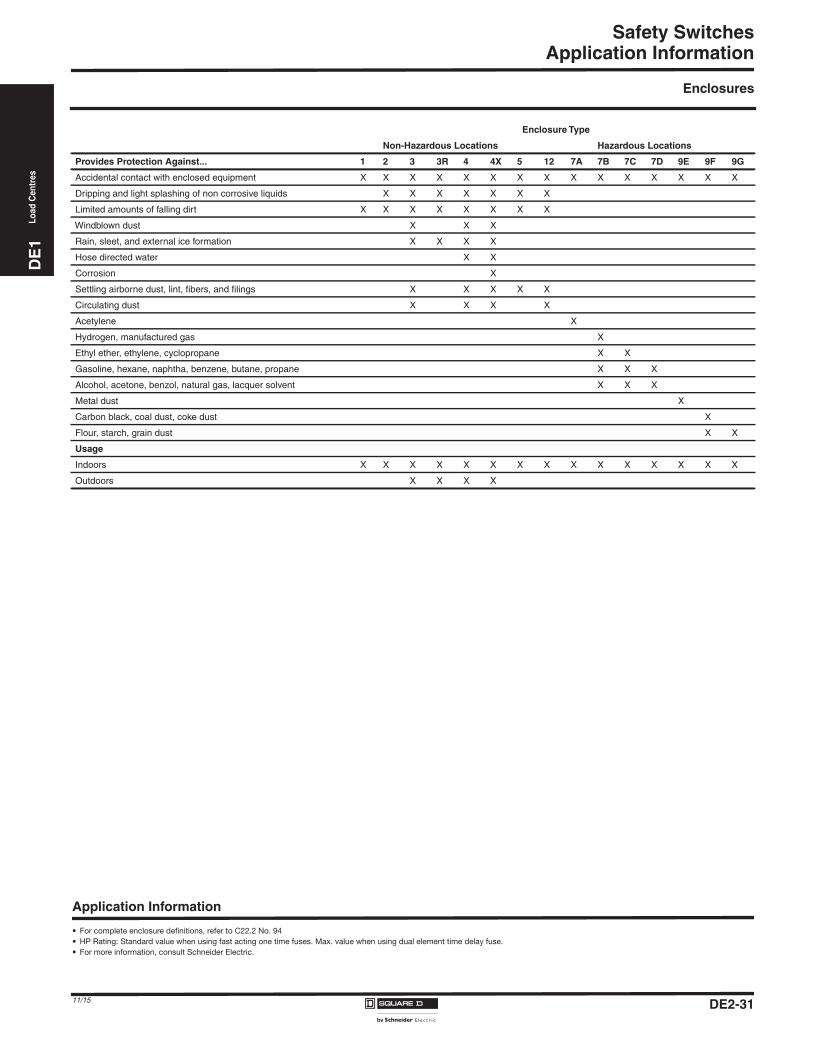
DE
1Lo
adC
entr
es
DE2_P21-31.fm Page 31 Thursday, December 10, 2015 11:28 PM
Safety SwitchesApplication Information
Enclosures
Enclosure Type
Non-Hazardous Locations Hazardous Locations
Provides Protection Against... 1 2 3 3R 4 4X 5 12 7A 7B 7C 7D 9E 9F 9G
Accidental contact with enclosed equipment X X X X X X X X X X X X X X X
Dripping and light splashing of non corrosive liquids X X X X X X X
Limited amounts of falling dirt X X X X X X X X
Windblown dust X X X
Rain, sleet, and external ice formation X X X X
Hose directed water X X
Corrosion X
Settling airborne dust, lint, fibers, and filings X X X X X
Circulating dust X X X X
Acetylene X
Hydrogen, manufactured gas X
Ethyl ether, ethylene, cyclopropane X X
Gasoline, hexane, naphtha, benzene, butane, propane X X X
Alcohol, acetone, benzol, natural gas, lacquer solvent X X X
Metal dust X
Carbon black, coal dust, coke dust X
Flour, starch, grain dust X X
Usage
Indoors X X X X X X X X X X X X X X X
Outdoors X X X X
Application Information
• For complete enclosure definitions, refer to C22.2 No. 94
• HP Rating: Standard value when using fast acting one time fuses. Max. value when using dual element time delay fuse.
• For more information, consult Schneider Electric.
DE2-3111/15


