
International Journal of Scientific & Engineering Research Volume 10, Issue 8, August-2019 1195 ISSN 2229-5518
IJSER © 2019 http://www.ijser.org
Deformation monitoring of structural elements using terrestrial laser scanner
Zaki M. Zeidan1 ,Ashraf A. Beshr2, Ashraf G. shehata3 1 Prof. of applied geodesy, Public Works department, Faculty of Engineering, Mansoura
University, [email protected]
2 Ph.D., Assistant Prof., Public Works department, Faculty of Engineering, Mansoura University, [email protected]
3 B. Sc., Demonstrator, Civil Engineering department, Delta University for Science and Technology,
Abstract:
Civil infrastructure systems is important in terms of both safety and serviceability. So, large
structure have been monitored using surveying techniques, while fine-scale monitoring of
structural components has been done with geotechnical instrumentation. The advantages and
disadvantages of using remote sensing methods, such as terrestrial laser scanning and digital close
range photogrammetry, for the purposes of precise 3D reconstruction and the estimation of
deflections in structural elements. This paper investigate that terrestrial laser scanner can be used
for the monitoring of concrete beams subjected to different loading conditions. The system used
does not require any physical targets. The setup was tested, and the beam deflections resulted from
the 3D model from terrestrial laser scanner system were compared to the ones from ANSYS
program. The experiments proved that it was possible to detect sub-millimeter level deformations
given the used equipment and the geometry of the setup. Calculations and analysis of results are
presented.
1. Introduction: Health monitoring of infrastructure systems is an important task and is usually done for two
reasons. The first one is safety (i.e. testing structural components or down-scaled models of
designed structures in order to estimate their maximum loading capacity), and the second one is
IJSER

International Journal of Scientific & Engineering Research Volume 10, Issue 8, August-2019 1196 ISSN 2229-5518
IJSER © 2019 http://www.ijser.org
serviceability (i.e. performing regularly scheduled monitoring procedures in order to assess
whether any maintenance is required on an already built structure.[1]
Traditionally, large structures such as dams, bridges, open-pit mines or high-rise buildings have
been monitored for overall deformations through ground based surveying techniques, i.e.
measurement of horizontal angles (or directions), zenith angles, slope distances and height
differences using precision grade total stations or theodolites and precision levels.
Recently, these techniques have been complemented by the use of global positioning methods,
where geodetic grade receivers and antennas collect signals from all visible satellites in a static
mode over long periods of time. [2].
Despite the wide variety of available surveying instruments and the well-established data
processing and network adjustment techniques, they can only observe a limited number of points,
which need to be carefully selected at the specific areas of anticipated deformation.
On the fine-scale side of structural health monitoring, the appearance of cracks and the failure of
foundations, walls, support columns or structural components in general, have been measured via
geotechnical techniques, for example using tilt meters, micrometers, inclinometers, wire strain
gauges or extensometers. [3].
In order to avoid the above mentioned problems in large structure and in fine-scale deformation
monitoring, remote sensing techniques can be used. In the last decade or so, sensors in the realm
of digital photogrammetry and laser scanning have started to be integrated into structural health
monitoring systems. The potential advantages of such remote sensing methods using cameras or
laser scanners, are that the object of interest does not have to be accessed while being measured,
and that permanent visual records (either images or point cloud scenes) of it are established for
each observed epoch of time. [4]
Also, objects can be reconstructed and deformations can be detected in 3D with a great amount of
redundancy, and the overall precision can be evaluated through a least squares adjustment. The
monitoring of building structures have an increasingly important role in the engineering field,
above all because they are concerned with the impact that such structures have in the area where
they were built. Often, when walking through the old town centers, we realize just how obsolete
and dangerous some buildings (even historic-cultural ones) are. The interest of some local
governments in this problem has led, in the last few years, to the study and the trying out of
measuring and monitoring methods which, quickly and at low cost, allow to define the extent of
IJSER

International Journal of Scientific & Engineering Research Volume 10, Issue 8, August-2019 1197 ISSN 2229-5518
IJSER © 2019 http://www.ijser.org
the deformation and the degrade in an accurate and reliable way. [5] The most frequent cases of
monitoring and control can be classified as follows: verification of the deformation and damage
caused by natural calamities (e.g. earthquakes), or malicious (e.g. fires); verification of the de
grade caused by weather conditions; verification of the present precarious state of a structure with
respect to its initial project; verification of the result of bad workmanship. The requirement,
therefore, is to identify techniques that are able to carry out accurate and reliable measuring of
structural deformation, and that are easy to obtain and are not too expensive. Moreover, in case of
the unstable buildings, especially if this are historic and cultural buildings, instruments are required
that do not make direct contact with the structure itself. Among all the geomatic techniques, that
have some of these characteristics, there are the following: measurement with Total Stations,
measurement with GNSS technology, close range photogrammetry and Terrestrial Laser Scanning.
[6]
one of studying the potential of Terrestrial Laser Scanning (TLS) in terms of monitoring structures
and buildings that have been damaged by natural calamities or by malicious intent.
2. TERRESTRIAL LASER SCANNER (TLS): The scanning of an object, or a building, consists of a series of scansions of the whole building,
both internally and externally. The result obtained is a multitude of points which allow for a 3D
reconstruction of the object with high accuracy.
FIG.1 Faro 3D laser scanner
IJSER
International Journal of Scientific & Engineering Research Volume 10, Issue 8, August-2019 1198 ISSN 2229-5518
IJSER © 2019 http://www.ijser.org
The Faro 3D laser Focus (fig. 1). It is a compact scanner characterized by an operative range that
varies between 0.6 m and 120 m with a linear distance error of ±2 mm for scanner object distances
comprised between 10 m and 25 m, and a noise (that is to say, the standard deviation of the values
with respect to the best-fit plan) which varies from between 0.6 mm and 10 mm with a reflectivity
of 90% and 2.2 mm to 25 mm with a reflectivity of 10%. It has a vertical visual field of 305° and
a horizontal one of 360°. The vertical and horizontal resolution is 0.009°. It has a scanning speed
of 976.000 points/sec, and a reduced weight. Incorporated into the laser is a color digital camera
with a resolution of 70 megapixels The laser scanning provides a point cloud with a high density
points, each one of them having the coordinates x, y, z, relative to an intrinsic reference system to
the instrument and the reflectivity, which is indicative of the physical characteristics of the surface
scanned. [7]
3. Monitoring the structural deformation of reinforced concrete beam:
This section discusses an application of structural member monitoring. It presents a real time
monitoring of a reinforced concrete simple beam subjected to specified concentrated loads. The
three geodetic techniques have been applied to determine the values and directions of the actual
deformations at specified sections and points under cases of loading. In deformation analysis, the
functional relationship between the acting forces and the resulting deformations should be
established. [8]
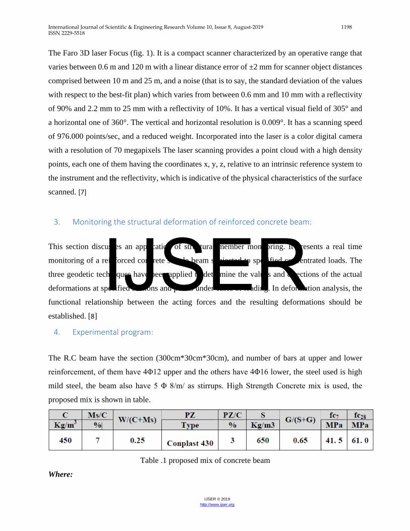
4. Experimental program:
The R.C beam have the section (300cm*30cm*30cm), and number of bars at upper and lower
reinforcement, of them have 4Φ12 upper and the others have 4Φ16 lower, the steel used is high
mild steel, the beam also have 5 Φ 8/m/ as stirrups. High Strength Concrete mix is used, the
proposed mix is shown in table.
Table .1 proposed mix of concrete beam
Where:
IJSER

International Journal of Scientific & Engineering Research Volume 10, Issue 8, August-2019 1199 ISSN 2229-5518
IJSER © 2019 http://www.ijser.org
C= Cement, Ms= Micro silica, PZ= Super plasticizer, S= Sand, G=Gravel
Fc = 7, 28 days Cube Compressive Strength.
Composition of High Strength Concrete and selective mixture and Cube Compressive Strength
Ordinary Portland cement and natural sand with high fineness modulus of 2.65 and Coarse
aggregate (natural gravel) with a maximum of 12 mm are used. Powder silica fume with SiO2 of
92%, specific gravity of 2.2 and specific surface area of 16.8 m2/g is used. High Range Water
Reducers super plasticizers) are used to improve both fresh and hardened concrete properties. The
use of High Strength Concrete in the construction industry has steadily increased over the past
years, which leads to the design of smaller sections. This is in turn reduces the dead weight,
allowing longer spans and more area of buildings. High Strength Concrete has many applications
as classical and non-classical applications. For these reasons, the High Reinforced Concrete is
applied.
Fig.3 R.C Beam from TLS
5. Analysis of observations:
IJSER

International Journal of Scientific & Engineering Research Volume 10, Issue 8, August-2019 1200 ISSN 2229-5518
IJSER © 2019 http://www.ijser.org
The beam is tested by using terrestrial laser scanner, the beam face is divided into 75 monitoring
points. The spatial distribution of these points should provide complete coverage of the beam as
shown in figure (4). A local three-dimensional rectangular coordinates system is needed to
calculate the spatial coordinates of any monitoring point. Such a system, presumably, has Xaxis is
chosen as a horizontal line parallel to the beam, the Y-axis is a horizontal line perpendicular to the
base direction and positive in the direction towards the beam, the Z- axis is a vertical line
determined by the vertical axis of the instrument.
Fig (4) monitoring point on the beam
6. Executive Summary:
The main objective of this experiment is to monitor for deformations resulting from the loading
test applied on 2 different beams material. (RC, Steel).
The scope of this document includes the results which will deliver reliable data prior to and after
applying every load which will be compared with three different techniques.
7. Experimental work by using TLS:
The last beam is tested by using the terrestrial laser scanner technique, the beam face is divided
into five critical monitoring points, and the spatial distribution of these points should provide
IJSER

International Journal of Scientific & Engineering Research Volume 10, Issue 8, August-2019 1201 ISSN 2229-5518
IJSER © 2019 http://www.ijser.org
complete coverage of the beam. The selected monitoring points are located where the maximum
deformations have been predicted such as point (3), plus a few points which are depending on
previous experience could signal any potential unpredictable behavior such as points (1, 2, 4 and
5).
Fig (5) critical Points to be monitored with the RC Beam
The adjusted coordinates and its surveying accuracy of each monitoring point to the case of loading
(0 ton) can be calculated. Table (2) shows a sample output of the adjusted coordinates (for Load P
= 0 ton).
IJSER

International Journal of Scientific & Engineering Research Volume 10, Issue 8, August-2019 1202 ISSN 2229-5518
IJSER © 2019 http://www.ijser.org
Fig (6) the RC beam in case of 0 ton load
Table (2) shows a sample output of the adjusted coordinates (for Load P = (0 ton)
point ID Coordinates
X (m) σX (mm) Y(m) σy (mm) Z(m) σz (mm) 1 -1.069 0.012 2.145 0.147 93.664 0.097 2 -0.455 0.124 2.239 0.216 93.677 0.028 3 -0.305 0.231 2.264 0.165 93.673 0.065 4 -0.175 0.021 2.285 0.187 93.661 0.032 5 0.386 0.178 2.378 0.098 93.664 0.014
Table (2) Adjusted coordinates of beam critical points and its accuracy (At P=0 ton)
The resulting surveying coordinates must be converted into meaningful engineering values. Point
displacements in three dimensions are calculated by differencing the adjusted coordinates at each
case of loading and the coordinates obtained at unload case.
IJSER

International Journal of Scientific & Engineering Research Volume 10, Issue 8, August-2019 1203 ISSN 2229-5518
IJSER © 2019 http://www.ijser.org
Fig (7) R.C beam from point cloud of TLS.
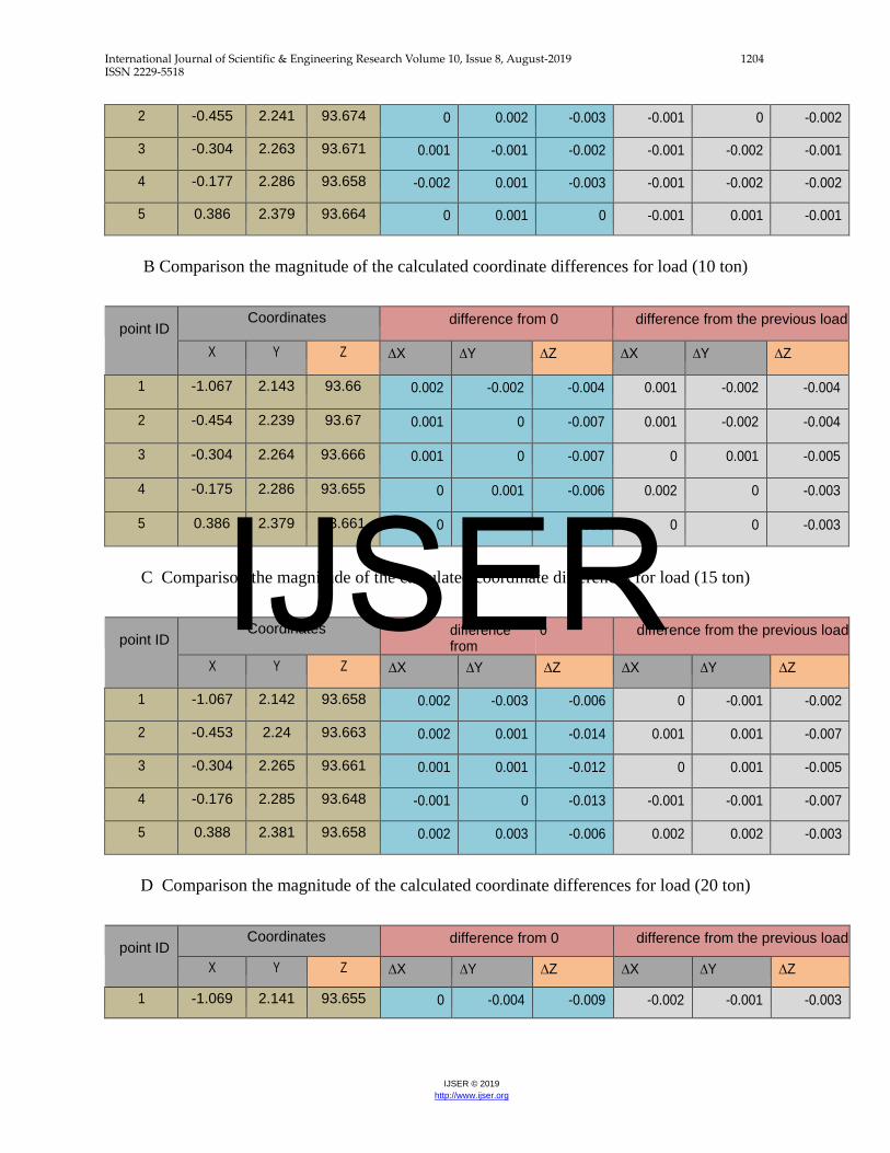
A comparison between the magnitudes of the calculated coordinate differences especially in Z
direction for all loads with the UN loaded case.
point ID Coordinates difference from 0 difference from the previous
load X Y Z ∆X ∆Y ∆Z ∆X ∆Y ∆Z
1 -1.067 2.146 93.662 0.002 0.001 -0.002 0.002 0.001 -0.002
2 -0.454 2.241 93.676 0.001 0.002 -0.001 0.001 0.002 -0.001
3 -0.303 2.265 93.672 0.002 0.001 -0.001 0.002 0.001 -0.001
4 -0.176 2.288 93.66 -0.001 0.003 -0.001 -0.001 0.003 -0.001
5 0.387 2.378 93.665 0.001 0 0.001 0.001 0 0.001
A Comparison the magnitude of the calculated coordinate differences for load (5 ton)
point ID Coordinates difference
from 0 difference from the previous load
X Y Z ∆X ∆Y ∆Z ∆X ∆Y ∆Z
1 -1.068 2.145 93.664 0.001 0 0 -0.001 -0.001 0.002
IJSER
International Journal of Scientific & Engineering Research Volume 10, Issue 8, August-2019 1204 ISSN 2229-5518
IJSER © 2019 http://www.ijser.org
2 -0.455 2.241 93.674 0 0.002 -0.003 -0.001 0 -0.002
3 -0.304 2.263 93.671 0.001 -0.001 -0.002 -0.001 -0.002 -0.001
4 -0.177 2.286 93.658 -0.002 0.001 -0.003 -0.001 -0.002 -0.002
5 0.386 2.379 93.664 0 0.001 0 -0.001 0.001 -0.001
B Comparison the magnitude of the calculated coordinate differences for load (10 ton)
point ID Coordinates difference from 0 difference from the previous load
X Y Z ∆X ∆Y ∆Z ∆X ∆Y ∆Z
1 -1.067 2.143 93.66 0.002 -0.002 -0.004 0.001 -0.002 -0.004
2 -0.454 2.239 93.67 0.001 0 -0.007 0.001 -0.002 -0.004
3 -0.304 2.264 93.666 0.001 0 -0.007 0 0.001 -0.005
4 -0.175 2.286 93.655 0 0.001 -0.006 0.002 0 -0.003
5 0.386 2.379 93.661 0 0.001 -0.003 0 0 -0.003
C Comparison the magnitude of the calculated coordinate differences for load (15 ton)
point ID Coordinates difference
from 0 difference from the previous load
X Y Z ∆X ∆Y ∆Z ∆X ∆Y ∆Z
1 -1.067 2.142 93.658 0.002 -0.003 -0.006 0 -0.001 -0.002
2 -0.453 2.24 93.663 0.002 0.001 -0.014 0.001 0.001 -0.007
3 -0.304 2.265 93.661 0.001 0.001 -0.012 0 0.001 -0.005
4 -0.176 2.285 93.648 -0.001 0 -0.013 -0.001 -0.001 -0.007
5 0.388 2.381 93.658 0.002 0.003 -0.006 0.002 0.002 -0.003
D Comparison the magnitude of the calculated coordinate differences for load (20 ton)
point ID Coordinates difference from 0 difference from the previous load
X Y Z ∆X ∆Y ∆Z ∆X ∆Y ∆Z
1 -1.069 2.141 93.655 0 -0.004 -0.009 -0.002 -0.001 -0.003
IJSER

International Journal of Scientific & Engineering Research Volume 10, Issue 8, August-2019 1205 ISSN 2229-5518
IJSER © 2019 http://www.ijser.org
2 -0.455 2.24 93.652 0 0.001 -0.025 -0.002 0 -0.011
3 -0.303 2.264 93.647 0.002 0 -0.026 0.001 -0.001 -0.014
4 -0.173 2.287 93.635 0.002 0.002 -0.026 0.003 0.002 -0.013
5 0.388 2.379 93.653 0.002 0.001 -0.011 0 -0.002 -0.005
E Comparison the magnitude of the calculated coordinate differences for load (23 ton)
Table (3) Comparison the magnitude of the calculated coordinate differences for all loads
It is obvious that the displacements of points (1and 5) are less than the displacement of points (2,
3 and 4). The difference appears because of the rotation of the beam. The upper surface of the
beam rotates more than the lower surface.
The max deformation for this beam from the initial coordinate at zero load and the final case of
load (23 ton) is 26 mm at the mid span (point 3).
8. R.C beam deformation from software (ANSYS):
The analysis and behavior of normal and high strength concrete beams under axial load will be
presented. This analysis predicts the behavior of system in elastic and post elastic stage, also drift
at each story, stress and strain for both concrete and reinforcement, cracks propagation, bending,
shear strength and deflection. The three dimensional nonlinear Finite element modeling of the
system was performed using “ANSYS (15)” Program. In this model, the nonlinearity of concrete
and reinforcement are considered. Concrete is modeled using a three dimensional reinforced
concrete element named “SOLID”, which is capable of cracking in tension and crushing in
compression. The main and web reinforcements are modeled using “STEEL” bar element within
the concrete “SOLID” one.
Organization of this Clause included review on the material model for concrete and reinforcement,
the input data (geometry, mesh data, loads, and boundary conditions), and finally discussed the
behavior of system under load increasing.
IJSER
International Journal of Scientific & Engineering Research Volume 10, Issue 8, August-2019 1206 ISSN 2229-5518
IJSER © 2019 http://www.ijser.org
9. Finite element model:
The finite element method using “ANSYS (15)” package can be used to closely predict the
behavior of normal and high strength concrete beams under axial load. The load-deflection
behavior, crack propagation, and first crack load, failure load and failure mode can be predicted
using the finite element method with an accuracy that is acceptable for engineering purposes.
10. Meshing:
To obtain good results from the Solid element, the use of a rectangular mesh is recommended.
Therefore, the mesh was set up such that square or rectangular elements were created (Figure 4.14).
The volume sweep command was used to mesh the steel plate and support. This properly sets the
width and length of elements in the plates to be consistent with the elements and nodes in the
concrete portions of the model.
The necessary element divisions are noted. The meshing of the reinforcement is a special case
compared to the volumes. No mesh of the reinforcement is needed because individual elements
were created in the modeling through the nodes created by the mesh of the concrete volume.
However, the necessary mesh attributes as described above need to be set before each section of
the reinforcement is created.
IJSER

International Journal of Scientific & Engineering Research Volume 10, Issue 8, August-2019 1207 ISSN 2229-5518
IJSER © 2019 http://www.ijser.org
Fig (8) mesh from ANSYS IJSER

International Journal of Scientific & Engineering Research Volume 10, Issue 8, August-2019 1208 ISSN 2229-5518
IJSER © 2019 http://www.ijser.org
FIG (9) MAX Deflection from ANSYS program
The beam, plates, and supports were modeled as volumes. Since the beam is being modeled, the
model is 3000mm. long, with a cross-section of 300*300mm. The zero values for the Z-
coordinates coincide with the center of the cross-section for the concrete beam and the max
deflection of the beam as shown in fig (9).
IJSER
International Journal of Scientific & Engineering Research Volume 10, Issue 8, August-2019 1209 ISSN 2229-5518
IJSER © 2019 http://www.ijser.org
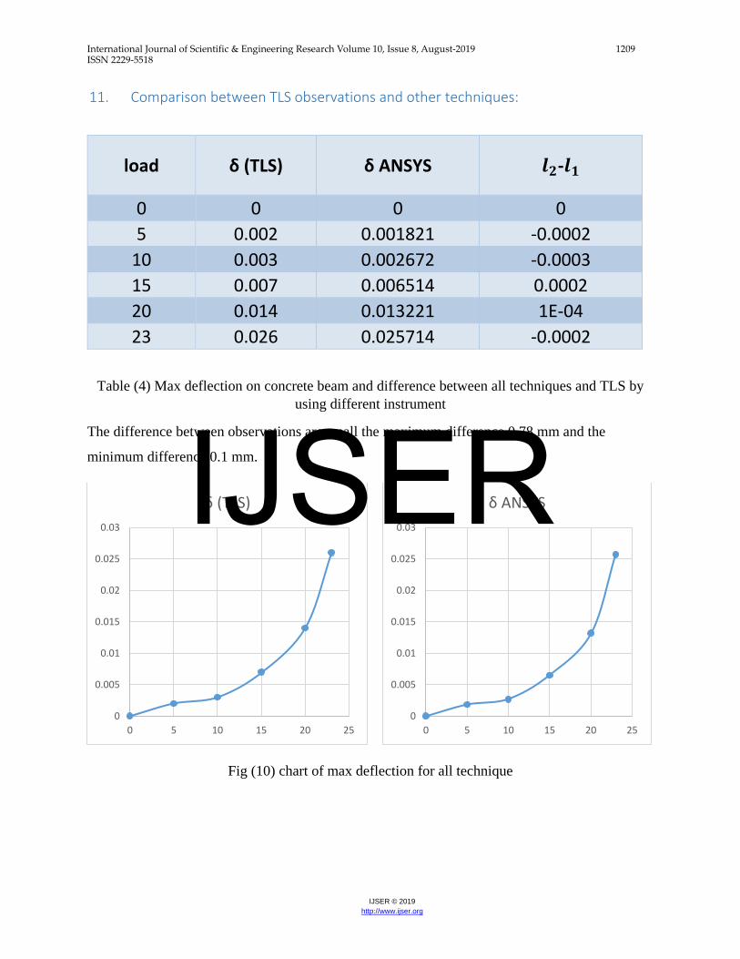
11. Comparison between TLS observations and other techniques:
load δ (TLS) δ ANSYS 𝒍𝒍𝟐𝟐-𝒍𝒍𝟏𝟏
0 0 0 0 5 0.002 0.001821 -0.0002
10 0.003 0.002672 -0.0003 15 0.007 0.006514 0.0002 20 0.014 0.013221 1E-04 23 0.026 0.025714 -0.0002
Table (4) Max deflection on concrete beam and difference between all techniques and TLS by using different instrument
The difference between observations are small the maximum difference 0.78 mm and the
minimum difference 0.1 mm.
Fig (10) chart of max deflection for all technique
0
0.005
0.01
0.015
0.02
0.025
0.03
0 5 10 15 20 25
δ (TLS)
0
0.005
0.01
0.015
0.02
0.025
0.03
0 5 10 15 20 25
δ ANSYSIJSER

International Journal of Scientific & Engineering Research Volume 10, Issue 8, August-2019 1210 ISSN 2229-5518
IJSER © 2019 http://www.ijser.org
12. Experimental program for Steel beam:
The steel beam section is I beam 180 mm shown in fig (16)
Fig (11) Steel I Beam dimensions
Fig (12) Steel Beam from TLS
IJSER

International Journal of Scientific & Engineering Research Volume 10, Issue 8, August-2019 1211 ISSN 2229-5518
IJSER © 2019 http://www.ijser.org
13. Analysis of observations:
The beam is tested by using terrestrial laser scanner, the beam face is divided into 9 monitoring
points. The spatial distribution of these points should provide complete coverage of the beam as
shown in figure (13). A local three-dimensional rectangular coordinates system is needed to
calculate the spatial coordinates of any monitoring point. Such a system, presumably, has X axis
is chosen as a horizontal line parallel to the beam, the Y-axis is a horizontal line perpendicular to
the base direction and positive in the direction towards the beam, the Z- axis is a vertical line
determined by the vertical axis of the instrument.
Fig (13) monitoring point on the beam
IJSER

International Journal of Scientific & Engineering Research Volume 10, Issue 8, August-2019 1212 ISSN 2229-5518
IJSER © 2019 http://www.ijser.org
14. Experimental work by using TLS:
The last beam is tested by using the terrestrial laser scanner technique, the beam face is divided
into five critical monitoring points, and the spatial distribution of these points should provide
complete coverage of the beam as shown in figure (14). The selected monitoring points are located
where the maximum deformations have been predicted such as point (3), plus a few points which
are depending on previous experience could signal any potential unpredictable behavior such as
points (1, 2, 4 and 5).
Fig (14) critical Points to be monitored with the RC Beam
The adjusted coordinates and its surveying accuracy of each monitoring point to the case of loading
(0 ton) can be calculated. Table (5) shows a sample output of the adjusted coordinates (for Load P
= 0 ton).
IJSER
International Journal of Scientific & Engineering Research Volume 10, Issue 8, August-2019 1213 ISSN 2229-5518
IJSER © 2019 http://www.ijser.org
point ID
Coordinates X (m) σX (mm) Y(m) σy (mm) Z(m) σz (mm)
1 -1.069 0.012 2.145 0.147 93.664 0.097 2 -0.455 0.124 2.239 0.216 93.677 0.028 3 -0.305 0.231 2.264 0.165 93.673 0.065 4 -0.175 0.021 2.285 0.187 93.661 0.032 5 0.386 0.178 2.378 0.098 93.664 0.014
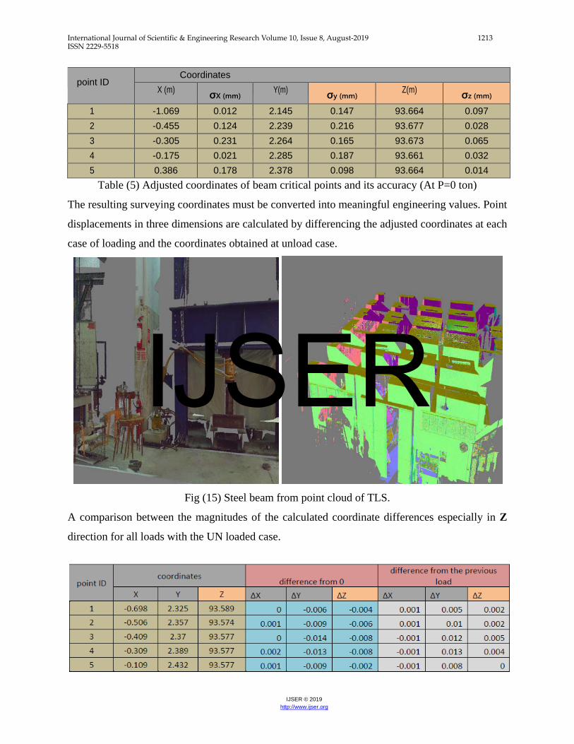
Table (5) Adjusted coordinates of beam critical points and its accuracy (At P=0 ton)
The resulting surveying coordinates must be converted into meaningful engineering values. Point
displacements in three dimensions are calculated by differencing the adjusted coordinates at each
case of loading and the coordinates obtained at unload case.
Fig (15) Steel beam from point cloud of TLS.
A comparison between the magnitudes of the calculated coordinate differences especially in Z
direction for all loads with the UN loaded case.
IJSER

International Journal of Scientific & Engineering Research Volume 10, Issue 8, August-2019 1214 ISSN 2229-5518
IJSER © 2019 http://www.ijser.org
Table (6) Comparison the magnitude of the calculated coordinate differences for failure load The vertical displacements at all loads and the failure load (P = 35 ton) is illustrated must be
compared.
It is obvious that the displacements of points (1and 5) are less than the displacement of points (2,
3 and 4). The difference appears because of the rotation of the beam. The upper surface of the
beam rotates more than the lower surface.
The max deformation for this beam from the initial coordinate at zero load and the final case of
load (35 ton) is 8 mm at the mid span (point 3).
15. Steel beam deformation from software (ANSYS):
The analysis and behavior of normal and high strength concrete beams under axial load will be
presented. This analysis predicts the behavior of system in elastic and post elastic stage, also drift
at each story, stress and strain for both concrete and reinforcement, cracks propagation, bending,
shear strength and deflection. The three dimensional nonlinear Finite element modeling of the
system was performed using “ANSYS (15)” Program. In this model, modeled using “STEEL”. IJSER

International Journal of Scientific & Engineering Research Volume 10, Issue 8, August-2019 1215 ISSN 2229-5518
IJSER © 2019 http://www.ijser.org
Fig (16) mesh from ANSYS
FIG (17) MAX Deflection from ANSYS program
IJSER

International Journal of Scientific & Engineering Research Volume 10, Issue 8, August-2019 1216 ISSN 2229-5518
IJSER © 2019 http://www.ijser.org
16. Comparison between TLS observations and other techniques:
load δ (TLS) δ ANSYS 𝒍𝒍𝟐𝟐-𝒍𝒍𝟏𝟏
0 0 0 0 10 0.004 0.003788 -0.00021 30 0.008 0.007646 -0.00035
Table (6) Max deflection and difference between all techniques and TLS on steel beam
The difference between observations are small the maximum difference 0.35 mm and the
minimum difference 0.2 mm.
Fig (18) chart of max deflection for all technique
0
0.001
0.002
0.003
0.004
0.005
0.006
0.007
0.008
0.009
0 10 20 30 40
δ (TLS)
0
0.001
0.002
0.003
0.004
0.005
0.006
0.007
0.008
0.009
0 10 20 30 40
δ ANSYSIJSER

International Journal of Scientific & Engineering Research Volume 10, Issue 8, August-2019 1217 ISSN 2229-5518
IJSER © 2019 http://www.ijser.org
17. Conclusion:
1. TLS is a very fast acquisition method and does not require deployment of any targets on
the object. Since the measurements are carried out touchless the performance and accuracy
of the measurements depend on the surface properties of the object.
2. The max deformation for R.C beam from the initial coordinate at zero load and the final
case of load (23 ton) is 26 mm at the mid span (point 3).
3. The max deformation for steel beam from the initial coordinate at zero load and the final
case of load (35 ton) is 8mm at the mid span (point 3).
4. TLS is considered as valuable tool for monitoring the structure elements deformation with
sufficient accuracy. It has also the ability to create 3D models of monitored object through
loading.
5. Using TLS is better than any other geometric instrument for monitor the structure elements
because its capability to draw and compare 3D model of element according to loading.
6. For R.C beam the maximum deformation from TLS observation (26 mm) and the
maximum difference between TLS and other technology (0.78 mm) and the minimum
difference (0.1 mm).
7. For steel beam the maximum deformation from TLS observation (8 mm) and the maximum
difference between TLS and other technology (0.35 mm) and the minimum difference (0.2
mm).
18. Acknowledgment:
It was our honor to deal with very helpful company (micro engineering technology in Egypt).
Thanks for all staff members for helping in the experimental works and field observations
collection data.
19. Reference:
1. Bond et al., (2008)”system and method for remote asset monitoring” worldtelemetry inc.
IJSER

International Journal of Scientific & Engineering Research Volume 10, Issue 8, August-2019 1218 ISSN 2229-5518
IJSER © 2019 http://www.ijser.org
2. I. Detchev a,*, A. Habib a, M. El-Badry b, (2011)” ESTIMATION OF VERTICAL DEFLECTIONS IN CONCRETE BEAMS THROUGH DIGITAL CLOSE RANGE PHOTOGRAMMETRY” International Archives of the Photogrammetry, Remote Sensing and Spatial Information Sciences.
3. I. Detchev a,*, A. Habib a, M. El-Badry b, (2014)” DEFORMATION MONITORING WITH OFF-THE-SHELF DIGITAL CAMERAS FOR CIVIL ENGINEERING FATIGUE TESTING” International Archives of the Photogrammetry, Remote Sensing and Spatial Information Sciences.
4. I. Wilczyńska, K. Ćmielewski, (2016)” Modern measurements techniques in structural monitoring on example of ceiling beams” Wroclaw University of Environmental and Life Sciences, Wroclaw, Poland.
5. K. L. El-Ashmawy, (2015)”A comparison between analytical aerial photogrammetry, laser scanning, total station and global positioning system surveys for generation of digital terrain model,” Geocarto International.
6. Morteza Daneshmand et al , (2018) ” 3D Scanning: A Comprehensive Survey ” arXiv:1801.08863v1 [cs.CV].
7. park, richard d. miller, jianghai xia, and julian ivanov, (2007) ”multichannel analysis of surface waves (masw)—active and passive methods” kansas geological survey, lawrence, usa.
8. S. El-Omari and O. Moselhi, (2008)”Integrating 3d laser scanning and photogrammetry for progress measurement of construction work, ”Automation in construction.
IJSER


