
1
A Flexible Control Architecture for Mobile Robots: An Application for a Walking Robot
Rowel O. Atienza Dept. of Electrical and Electronics Engineering University of the Philippines-Diliman 1101 Quezon City Philippines Email: [email protected]
Marcelo H. Ang Jr. Dept. of Mechanical and Production Engineering National University of Singapore 10 Kent Ridge Crescent Singapore 119260 Email: [email protected]
Abstract
To get the best features of both deliberative and reactive controllers, present mobile robot control
architectures are designed to accommodate both types of controller. However, these architectures
are still very rigidly structured thus deliberative modules are always assigned to the same role as a
high-level planner or sequencer while low-level reactive modules are still the ones directly
interacting with the robot environment. Furthermore, within these architectures communication
and interface between modules are if not strongly established, they are very complex thus making
them unsuitable for simple robotic systems. Our idea in this paper is to present a control
architecture that is flexible in the sense that it can easily integrate both reactive and deliberative
modules but not necessarily restricting the role of each type of controller. Communication
between modules is through simple arbitration schemes while interface is by connecting a
common communication line between modules and simple read and/or write access of data
objects. On top of these features, the proposed control architecture is scalable and exhibits
graceful degradation when some of the modules fail, similar to the present mobile robot
architectures. Our idea has enabled our four-legged robot to walk autonomously in a structured
uneven terrain.
1.0 Introduction
Early works in mobile robot control architecture emphasized building modules for sensing the
environment, modeling it, planning based on this perceived model and executing the planned
action to achieve a certain task. Brooks [Brooks, 1991] named this design approach sense-model-
plan-act (SMPA) while Maes [Maes, 1993] called it knowledge-based. A mobile robot employing
a knowledge-based controller tries to achieve its goal by following closely the sense-model-plan-
act procedure. Although the resulting overall behavior is predictable, the controller becomes slow
and complex as it deals with a dynamic environment. Most of the controller processing time is

2
consumed in building a model, doing general perception and planning [Maes, 1993]. There is
little amount of computation done in acting [Brooks, 1991]. In the six-legged Ambler for
example, as the robot walks its forceful interaction with the environment causes rapidly evolving
events like bumps, slips and tips which it can not easily keep up with [Wettergreen and Thorpe,
1992; Wettergreen and Thorpe, 1993]. A knowledge-based mobile robot also tends to react
differently when confronted with a situation that is not part of its knowledge base.
In 1986, Brooks [Brooks, 1986] proposed a radically different approach in the design of
mobile robot control architecture to address the drawbacks of knowledge-based controllers. Using
subsumption architecture, he built a controller for mobile robots made up of several layers that
operate at increasing level of competence. Each level of competence is composed of several task-
achieving behaviors or modules interacting with each other and the environment to achieve a
certain goal. This design approach was later called behavior-based [Brooks, 1991; Maes, 1993].
In the field of walking robots, at around 1989 Brooks implemented this approach to a six-legged
robot Genghis [Brooks, 1989]. Since it was introduced behavior-based approach gained
considerable success because it can deliver solutions that were expected from a knowledge-based
controller. When confronted by a dynamic environment, a behavior-based robot can react fast
because of the direct coupling between its behaviors and the sense states. It can also handle
unpredictable situations to a large extent because its behaviors try to achieve a common goal
without restricting themselves within a predefined set of rules. The robot controller can be built
incrementally, thus making it highly modular and easy to construct. However, this reactive
approach still suffers some limitations. As pointed out in the eight-legged Dante II [Wettergreen
and Thorpe, 1996] for example, the behavior-based controller lacks the foresight to be productive
and efficient in an unstructured environment. Actions are confined to reactions to sensors and
change of state of other behavioral modules. When encountering an insurmountable obstacle, the
behavior-based controller maneuvers over it only after the obstacles is detected by bump sensors.
If additional sensing and planning are incorporated, the direction of the robot can be changed
early and before the obstacle is encountered thus avoiding inefficient and unproductive
maneuvers. Another shortcoming of behavior-based controllers is the difficulty in predicting the
system’s overall behavior when the interaction between behaviors increases [Simmons, 1994]. In
the six-legged Genghis for example, it is difficult to predict the resulting global behavior as the
number of behavior grows and the interaction between them increases.
During the last decade, attempts to design robot control systems utilizing both types of
controllers have gained much interest to address the problems involved when either controller is
implemented independently. Two prominent examples in the field of walking robots are the eight-

3
legged robot Dante II [Wettergreen and Thorpe, 1996] and the six-legged robot Ambler [Simmons,
1994]. The Dante II control architecture integrates planning by parameterizing each behavior in
the originally formulated behavior-based controller [Wettergreen, et. al., 1995]. With a narrowly
focused planner examining the internal and external states, it can avoid unnecessary collisions
and it can increase walking speed when the terrain condition improves. On the other hand, by
layering reactive behaviors onto deliberative components, the walking rover Ambler is able to
navigate autonomously on outdoor rough terrain. In this technique called structured control
approach, knowledge-based components handle nominal situations and the reactive behaviors
handle exceptional situations. The deliberative components plan for safe and efficient moves
based on a host of robot and environment constraints. The reactive components detect and handle
deviations arising from sensor and actuator uncertainty. To support the structured control
approach, the Task Control Architecture (TCA) was formulated.
Although both the control systems of Ambler and Dante II are unique on their own ways,
they derive inspiration from control architectures originally formulated for wheeled mobile
robots. Most notable examples are the works of Firby [Firby, 1989] on Reactive Action Packages
Architecture (RAP), Connell [Connel, 1992] on Servo, Subsumption and Symbolic Systems
Architecture (SSS) and Gat [Gat, 1992] on ATLANTIS Architecture. In these architectures,
lower-level reactive behaviors operate under the supervision of a higher-level deliberative planner
or sequencer. To the best of its knowledge, the planner supplies information on a certain set of
reactive behaviors to accomplish a task. The lower-level reactive behaviors, however, can still
operate the robot though less intelligently even without instructions from the higher-level planner.
In this case, the controller degenerates to a purely reactive one. All of these four architectures
allow incremental development of the overall control system. Thus, complex systems can be
developed step by step.
However, the main limitation of the above control architectures is that the role of the
deliberative components is still confined to high-level planning or sequencing of tasks of lower-
level reactive modules. The control architectures are rigidly structured that it is difficult to
accommodate reactive modules to do planning or sequencing or to try deliberative modules to
interact directly with the environment. Since there has been no definitive study claiming that
reactive components are ineffective planner or sequencer or that at all cases, deliberative
components can not handle direct interaction with dynamic environments, then robot control
architectures should be flexible.
In addition to this main limitation, communication and interface between modules in
these hybrid architectures are if not well structured, they are very complex for simple robotic

4
systems. For example, in the ATLANTIS [Gat, 1992] there is no mention on how the sequencer
communicates via channels. There is also no mention on the structure of the parameter being
passed on this channel. The interface between the controller, sequencer and deliberator is also not
well defined. On the other hand in TCA [Simmons, 1994] although communication and interface
between modules are very defined, they are also very complex. Modules pass complex data that
include structures, pointers, arrays, strings, etc. This information is converted to a byte stream
that is passed to a Central Control Module via Ethernet sockets. In most cases, most robotic
systems do not need such complex communication and interface between controller modules.
Meanwhile, the SSS [Connel, 1992] architecture has a very well defined communication between
modules through the use command transformations between servo, subsumption and symbolic
layers. However, the interface between modules is not very clear.
In this paper, we present a control architecture that is flexible in terms of its ability to
accommodate both deliberative and reactive controllers without restricting the role of deliberative
modules to planning and sequencing or the reactive modules to direct interaction with the
environment. Deliberative and reactive modules are embedded within the control architecture.
They do not follow a three-layer architecture similar to SSS or ATLANTIS or several
independent modules connected to a Central Control Module similar to TCA. To make an
analogy, the proposed control architecture is like a jigsaw puzzle where each piece can be a
deliberative or reactive controller playing a certain role in the whole control system. This can
only be done only if the communication and interface between modules and controllers are well
defined. Communication within a controller is done by passing around a common data object
using simple arbitration schemes with proper read and/or write access to each member of data
object. Communication with other controllers is done by giving a proper read access to each
member of the data objects of the two controllers. Interface within a controller is done through a
common communication channel connecting all modules in a controller while interface with
another controller is through a shared module. To make an analogy, communication and interface
within a controller is similar to a Local Area Network (LAN) composed of several terminals (the
modules) connected by a common cable. Communication and interface with another controller is
like connecting to another LAN using a common terminal (the shared module) with two network
interface cards. The overall control system can be seen as an interconnected network of different
controllers working on different tasks yet still acting as a whole
The proposed control system has been successfully implemented on a real four-legged
robot. As will be discussed in the following sections, the National University of Singapore (NUS)
quadruped is able to walk with some sense of direction using a control system that is partly

5
behavior-based and partly knowledge-based. The implementation only needs a high-level
programming language like C and a real-time operating system. Since ordinary real-time system
primitives are used for control and communication between modules, there is no need to create a
special programming language. There is also no dilemma in selecting the reactive modules
needed to accomplish a certain task unlike the hybrid systems mentioned earlier such as the
ATLANTIS or TCA. Since reactive modules have been carefully selected and optimized, they
are always allowed to run whenever possible.
The results of the implementation of the proposed control system are presented before
this paper is concluded. Experimental data show the effectiveness of the proposed architecture.
2.0 A Flexible Control Architecture Applied to Legged Robot
In this section a mobile robot control architecture where both reactive and deliberative
controllers can be easily integrated and tested is discussed. The idea also includes how to build a
complex control system that is easy to upgrade and maintain. The first task is defined and its
controller is built. An example of a task is enabling the legged robot to walk autonomously on
uneven terrain. The controller can either be one of the two types of controller. In either case, it is
composed of a group of modules. The group of modules can either be a collection of task-
achieving behaviors/modules or it can be modules of the sense-model-plan-act procedure. Within
a group, modules compete or cooperate in the use of their single communication line. If the group
constitutes a reactive controller, the communication line connects all modules similar to network
of different computer terminals connected by a common cable. The communication line is always
connected to a module that directly executes the action to achieve the task. We call this module
the job processor module (JPM). It is one of the modules in the group of the reactive controller
that is directly responsible for the task delegated to the group. In case the group represents a
deliberative controller, the sensing, modeling, planning and acting modules are connected in
series in a single loop using a common communication line. The “act” module serves as its JPM.
Competition happens between task-achieving behaviors while cooperation exists between
modules of the sense-model-plan-act procedure. When modules compete in the use of
communication line, arbitration is done through priority or first-come-first serve basis.
Every module generates an output message or data based on the current information in
hand. It may be used by another module or it may become a job request for the JPM. Whenever
the JPM receives a job request, it performs necessary actions to achieve the task. An example of
JPM is a servo control system positioning the legs of the walking robot. It receives job requests

6
in the form of desired leg positions. In the SMPA procedure, the JPM receives pure job requests
from the “plan” module. Some modules generate non-job requests. For example, sensor modules
generate sensor data instead of desired leg positions. Other modules may use the non-job request
data in order to generate a new output. For example, an obstacle avoiding module needs the non-
job request data from an obstacle detecting module in order to generate an avoid obstacle job
request for the JPM.
Since a group of modules has only one task, it has only one JPM. However, any of the
other modules can become the JPM of another group of modules. In this way, the JPM also serves
as an interface between different groups or tasks similar to the role of a terminal that has two
network interface cards connecting two separate LANs. As a module, the JPM can also generate
its own output and send it in broadcast mode. For example, it can send the current leg positions to
other modules.
Once a suitable controller has been built for the first task, additional goals can be set.
Therefore, through the continuous process of upgrading the original set of task(s), the capabilities
of the robot are improved. For example, if we want to incorporate navigational capability to a
legged robot that knows how to walk on uneven terrain, we create a second group of modules
with the navigator as their JPM. The navigator is in turn incorporated as a higher priority module
in the first group of modules controlling walking on uneven terrain. It dictates the direction the
walking robot should take. This results in a legged robot that knows not only how to walk on
uneven terrain but also which direction to take.
The control architecture has allowed the NUS quadruped to develop its capability to walk
on uneven terrain. We use behavior-based control to implement reactive control because it is
known to be more suitable for this task and it is easier to design [Brooks, 1989]. The levels of
competence are identified through horizontal task decomposition. The components of each level
of competence (the task-achieving behaviors or modules) are then built one by one. The JPM is
assigned to the servo control system module that moves the legs (and body) to their desired
positions. All modules are run in parallel. The first batch of modules is connected together in a
simple priority-based architecture to form the first level of competence. The higher levels of
competence are formed when lower levels of competence are upgraded. The architecture uses two
simple arbitration schemes between modules, one for modules of different priorities (priority
basis) and one for modules of equal priorities (first-come-first-serve basis). The communication
between modules within a controller is through a shared memory. The shared memory contains
all relevant information on the task. The resulting representation of the architecture is more
concise as only one communication line is needed.

7
Using a real-time multi-tasking system, RTKernel [RTKernel Version 4.5 Manual], the
parallel processing requirement of the controller is simulated. Each module is a C function. All of
them are run in parallel in a non-preemptive scheduling system. The arbitration schemes are
implemented through the real-time kernel primitives.
When the behavior-based controller is employed, the NUS quadruped can manage to
walk on a flat surface with artificial obstacles as shown by the experimental results. Although the
quadruped knows how to walk along different directions, it does not have a direction-generating
module. Therefore, a navigator module is added. This forms the second JPM. A simple
deliberative (a knowledge-based) module controls the navigator. It dictates the direction based on
the current status of the robot. In order to get information on the status of the robot, the simple
knowledge-based module is allowed to read the data the navigator has. Only the navigator is
permitted to write on the output line since it is also a member of the first group of modules. In
this way, privacy of data between groups is maintained.
The second group of modules shows that the two types of controller can coexist together
in one control architecture. A knowledge-based controller is in charge on a small portion of the
overall control system that is dominated by a behavior-based controller. The second group of
modules can also be removed without causing total disruption in the operation of the overall
control system thus exhibiting the maintainability of the proposed architecture.
The next sections present the NUS quadruped and the development of its controller using
the proposed architecture. The task-achieving behaviors used are enumerated first. Then, the first
group is incrementally developed.
3.0 The NUS Quadruped
A photograph of the NUS quadruped is shown in Figure 1. The robot body is 50 cm wide,
50 cm long and 30 cm high. Attached to the body are four pantograph legs, each with three
degrees of freedom. The workspace volume of each leg is 20 cm wide, 28 cm long and 20 cm
high corresponding to x, y and z degrees of freedom. A 72W DC servomotor through a ball or
lead screw actuates each joint of a leg.
Shaft position is measured using an optical encoder connected at the other end of the
motor. On top of the robot, a digital roll and pitch sensor is placed. The power, control and
communication signals are transmitted through a 4m umbilical cable connected at the rear of the
quadruped. At the other end of the umbilical cord are a host Pentium 90MHz PC, 12 DC motor
power drives and 3 DC power supplies. Inside the host PC are auxiliary cards for the 12 D/A
converters, 12 optical encoder counters and several I/O ports. The controller gathers data from the

8
quadruped through the counters and I/O ports. Then, it moves the robot to a new desired position
by issuing a voltage to each motor through its D/A converter and motor drive.
Figure 1. The NUS Quadruped maneuvering an obstacle. The corresponding leg number assignment is shown.
4.0 The Task-achieving Behaviors of the NUS Quadruped
Using horizontal task decomposition of enabling the NUS quadruped to walk on uneven terrain,
the following levels of competence are identified:
• Rest
• Standup pose
• Walking on even terrain
• Detecting and maneuvering obstacles
The task-achieving behaviors comprising these levels of competence are built as follows. (The
variable x below can be 1, 2, 3 or 4 corresponding to legs 1, 2, 3 and 4.)
To be able to move the legs and body, module ServoControl is developed. It is a low-level
fuzzy logic control system that drives all joints in a synchronized manner to achieve their desired
positions [Atienza and Ang, 1998]. The second behavior developed named GoHome enables the
robot to achieve home or rest position during start up by locating the origin of each joint. Standup
module is built next so that the quadruped can assume standing up posture from its rest position.
Once the quadruped can already stand up, the next set of behaviors enables it to walk on even
terrain. This includes UpLegx, AdvanceLegx, DownLegx, Walk and Balance. To be able to walk
leg 3 leg 2
leg 4
leg 1

9
on uneven terrain, an additional set of modules is developed to detect and maneuver obstacles. To
collect data from sensors, FSensor, IRSensor and RPSensor are added. By analyzing these data,
the quadruped is able to detect, step over and avoid obstacles while maintaining its body plane
normal to the gravitational vector using CollideLegx, FootxForce, RPxBalance and AdjustRPH.
Each of these modules can be described in terms of its function(s) or behavior(s). Each has at
least one input (the data object called robot information) and one output (for updated robot
information). The term robot information includes as members:
• current position of each axis
• desired position of each axis
• force exerted on each foot
• status of infrared sensors
• roll and pitch data
• current direction of the robot
• wake up/trigger or enable signal and its destination module
• suspend or suppress signal and its destination module
• current state of each module (e.g. active, suspended, etc.)
The modules communicate with each other by passing member(s) of robot information in the
form of message or data. Each module uses the copy of its robot information to determine its
action. Every module has its own timer and it may have additional inputs and/or outputs. The
representation of a typical module is shown in Fig. 2.
Figure 2. A typical module in the proposed control architecture
Below is a summary of the description of each of these task-achieving behaviors. These
behaviors will comprise the first group of modules in the proposed control architecture.
1. ServoControl implements the fuzzy logic control engine that moves all joints from the current
to the desired positions in a smooth and synchronized manner. Additional input: optical encoder
count from each motor. Additional output: voltage for each joint’s DC motor.
2. GoHome sets the target positions of all joints causing the robot to assume home or rest
position. This behavior is activated during power up and remains dormant after home or rest
position is reached.
Moduleadditional output
updated robot information
additional input
robot information
10
3. Once the robot assumes home or rest position, Standup sets the target positions of all joints
causing it to achieve standing up posture.
4. Once UpLegx receives a trigger or wake up signal, it sets the target position of leg x causing it
to lift up.
5. Once leg x is lifted up from the ground by some distance, AdvanceLegx sets the target position
of leg x causing it to advance to the general direction of the robot. The six possible directions the
robot can go are forward, backward, to the right, to the left, clockwise and counterclockwise.
6. Once leg x is advanced by some amount, DownLegx sets the target position of leg x causing it
to lower down.
7. If the center of gravity is not within the support triangle and a leg is to be lifted up, Balance
sets the target positions of all legs causing the robot body to shift its center of gravity (CG) to a
stable location.
8. Walk generates the gait pattern for a particular direction of motion of the robot by sending a
trigger signal to the leg that should transfer.
9. IRSensor gathers data from the eight infrared sensors mounted on top of each foot. Additional
input: infrared sensor status.
10. FSensor collects data from the force sensor mounted on each foot. Additional Input: force
sensor data.
11. RPSensor gathers roll and pitch data from the attitude sensor. Additional input: attitude sensor
data.
12. Once an object along the direction of advance of foot x is detected from the infrared sensor
data, CollideLegx sets the target position of leg x causing it to lift up and avoid the obstacle.
13. Once the force on foot x exceeds a certain threshold, FootxForce sets the target position of
leg x causing it to stop. Also, if the force exerted against foot x is insufficient and leg x has
already reached its lowest position, FootxForce sets the target positions of all other legs causing
the body of the robot to lower down until enough force is exerted against foot x.
14. Once the roll and pitch of the body go beyond their thresholds (error windows) because leg x
was lowered down too far, BalanceRPx sets its new target position causing it to retract and adjust
the attitude if possible.
15. AdjustRPH sets the target positions of all legs causing the body to be lifted up when it is
sagging down. Afterwards, AdjustRPH adjusts the target positions of all legs, one pair at a time, if
the roll and pitch go beyond their thresholds.

11
5.0 The Interaction of Behavior Modules within the Control Architecture
In this section, we integrate and test all modules discussed previously using the proposed control
architecture. The first JPM is assigned to ServoControl. Therefore, the goal of every module is
to grab the communication line and pass its output message (an update on robot information). If
the message is a job request, it is immediately processed by the JPM. Other types of message are
used by other modules. The JPM also sends data in the form of current leg positions. Arbitration
on which module can use the communication line is determined though priority or first-come-
first-serve basis. We use an encircled ‘s’ to implement the priority basis. It means that the output
line of the module without an arrow entering ‘s’ can be suppressed/enabled by the upper level
module’s output line. The upper module can also suspend/wake up the operation of the lower
module. On the other hand, an encircled ‘e’ means that all modules connected to it have equal
priorities. When a module is writing on the output line, the rest waits for its completion (first-
come-first-serve basis).
Using the proposed architecture, the four levels of competence are developed
incrementally as follows.
1. Rest . By connecting module GoHome to ServoControl, the quadruped assumes home or rest
position during power up. Fig. 3 illustrates the control architecture. GoHome sends its job request
(all joints go to their origins) to the JPM. ServoControl in turn moves all joins towards their
origins (rest position).
Figure 3. Rest Competence
2. Standup pose competence is developed by the quadruped when the Standup module is added as
shown in Fig. 4. Once Standup notices the robot is in rest position, it grabs the communication
line and sends a job request (extend all legs and lift up the body) to the JPM. ServoControl in turn
processes the job request and the quadruped assumes standing up posture.
ServoControl
GoHomeDC motor
optical encoder

12
Figure 4. Standup pose competence
3. Walking on even terrain competence is evolved when the UpLegx, AdvanceLegx, DownLegx,
Balance and Walk modules are added as shown in Fig. 5. . When this figure is expanded for all
legs, the group of behaviors for legs 1, 2, 3 and 4 (i.e. x=1, 2, 3 and 4) can be put side by side in
any order. Arbitration between these four groups can be through first-come-first-serve basis.
Figure 5. Walking on even terrain competence
If the robot is in standing up position, Walk momentarily suppresses all outputs coming from
the lower-level modules and sends a trigger signal through the communication line to the UpLegx
associated with the first leg to move. The message passes through the JPM to reach its destination
(UpLegx). Issuing the trigger signal signifies the start of walk.
To illustrate the situation, suppose the quadruped wants to move forward (+y type or 2(rear-
left)-1(front-left)-3(rear-right)-4(front-right) leg sequence) and the rear left leg is selected, Walk
momentarily suppresses all lower-level outputs and sends a trigger signal to UpLeg2. If Balance
sees that it will not be possible to lift up leg 2, it suppresses the output of UpLeg2. Then, it sends
a job request to the JPM to stop lifting up leg 2 and move the CG to well within the support
triangle (legs 1, 3 and 4) while advancing the body. Afterwards, Balance releases the output line
and UpLeg2 continues. When leg 2 reaches some distance from the ground, AdvanceLeg2 sends a
suspend signal to UpLeg2. Then, it issues a job request to the JPM to stop leg 2 from lifting up
ServoControl
GoHomeDC motor
Standup
DownLegx
AdvanceLegx
UpLegx
Walk
Balance
s
s
s
s
s
s
optical encoder
ServoControl
GoHomeDC motor
Standup
s
optical encoder

13
further and advance it in the direction of motion of the robot. When leg 2 reaches some distance,
DownLeg2 suppresses the output of AdvanceLeg2 and it sends its own job request to the JPM to
stop leg 2 from advancing and start lowering it down. After leg 2 has reached the ground,
DownLeg2 releases the output line. Notice that at this point, although AdvanceLeg2 is still active,
it is no longer sending a job request. The condition, leg 2 is lifted up from the ground, is no
longer satisfied. Also, UpLeg2 is already in a wait state ready to receive a new trigger signal.
After transferring leg 2, Walk continues on sending trigger signals to legs 1, 3 and 4 in that order.
In each case, the same sequence of events happens as in leg 2. When the trigger goes back to leg
2, one full forward gait pattern has just completed. Notice that the effect of advancing the legs
and body is translating the quadruped forward. The robot can also move in a different direction
using the corresponding gait pattern [McGhee and Frank, 1968]. Since the different gait patterns
are already known to Walk, it is just a matter of changing the default direction (forward) so that
the robot can change its course.
4. Developing the competence to detect and maneuver obstacles is developed when RPSensor,
FSensor, IRSensor, FootxForce, CollideLegx, BalanceRPx and AdjustRPH modules are added as
shown in Fig. 6. RPSensor, FSensor and IRSensor are the modules that collect data from the
sensors. They are given a higher priority to eliminate incorrect outputs to be generated by other
modules because of outdated sensor data. BalanceRPx, FootxForcex, CollideLegx and
AdjustRPH detect the obstacle and enable the robot to maneuver around it.
To illustrate this competence, suppose during the time when leg 1 is advancing (forward
walk), if CollideLeg1 detects an obstacle along the direction of motion, it suppresses the output of
AdvanceLeg1. Then, it sends a job request to the JPM to stop leg1 from advancing and lift it up
further until the obstacle is no longer seen. Afterwards, CollideLeg1 releases the output line and
AdvanceLeg1 continues as if nothing happened. If the object is wide enough, leg 1 steps on it. In
that case, if the force on foot 1 exceeds the threshold when DownLeg1 requested the JPM to
lower it down, Foot1Force sends its own job request to stop leg 1. In this way, the robot roll and
pitch are prevented from deviating excessively. When leg 1 stops moving down, BalanceRP1
performs further attitude adjustment to maintain the body plane horizontal. This is done by
issuing ‘retract leg 1 incrementally’ request to the JPM until it is still possible to improve the
attitude. The Walk module continues sending trigger signal to UpLeg3 only when BalanceRP1
has finished its job.

14
Figure 6. Detecting and maneuvering obstacles competence. When this figure is expanded for all legs, the group of behaviors for legs 1, 2, 3 and 4 (i.e. x=1, 2, 3 and 4) can be put side by side in any order. Arbitration between these four groups can be through first-come-first-serve basis. When this competence is added, the quadruped is able to walk on uneven terrain. Navigate and NavigatorKB can be connected as an upgrade to give navigational capability to the robot.
AdjustRPH complements BalanceRPx by making sure that the minimum body height and the
desired roll and pitch are maintained every half-gait pattern execution (after every two legs are
moved). It is activated before or after Balance shifts the CG. Once it gets activated, it sends job
requests to the JPM to adjust the attitude and maintain the minimum body height.
With this additional competence, the quadruped is able to walk on uneven terrain. It can also
climb up and descend a wide stair with small steps because of AdjustRPH and FootxForce. For
example, in case all legs have already reached the top of the first step, the bottom part of the
quadruped’s body will be very near the new flat surface. This happens because when the robot is
climbing, it can be noticed that body unlike all feet is still on the same elevation with respect to
the floor surface. When AdjustRPH notices that the body height is below minimum, it sends a job
request to the JPM to regain the desired height so that the quadruped can scale up another step.
On the other hand, suppose the robot is about to descend the stair say for example with leg 4
advancing. When Foot4Force sees that DownLeg4 has already given the lowest level for leg 4
but the force is still insufficient, it sends a job request to the JPM to lower down the body until
foot 4 registers sufficient force reading. In this way, the robot is able to descend the stair.
ServoControl
GoHomeDC motor
Standup
UpLegx
Balance
s
s
s
s
s
s
DownLegx
AdvanceLegx
CollideLegx
BalanceRPx
FootxForce
Walk
Navigate
AdjustRPH
RPSensor
FSensor
IRSensor
s
s
ss
ss
attitudesensor
forcesensor
infraredsensor
e
e
optical encoder
NavigatorKB

15
However, in the present situation in case the body has been lowered down fully but there is still
no sufficient force on foot 4, the robot stops moving and will not try to recover.
5.1 A Simple Upgrade
Using the behavior-based controller developed above, the quadruped is able to walk
autonomously on uneven terrain. However, when it encounters an insurmountable obstacle, it gets
stuck. To solve this problem, an additional module to the first group, Navigate, is incorporated. It
is given a higher priority. Since Navigate is only a mechanism that receives robot information and
sends job request to the JPM, another module that controls it is built. NavigatorKB is a simple
knowledge base that tells Navigate the direction it should send given the current situation. (In the
current implementation, NavigateKB is a simple if-else ladder that changes the direction of the
robot when it gets stuck). In order to get information on the status of the robot, the NavigateKB
module is allowed to read the copy of robot information in the Navigate module. Using the
control architecture, these two modules comprising the second group can be easily incorporated
as shown by the broken line in Fig. 6. A more complex group of behaviors can replace
NavigateKB if needed. It can be composed of explicit sense-model-plan-act modules or a group
of task-achieving behaviors trying to control Navigate. In either case, the flexibility of the
proposed control architecture is demonstrated.
6.0 Implementation Using a real-time multi-tasking system RTKernel, the parallel processing requirement of the
controller is simulated. The controller is implemented in C language. The inter-module
communication is executed through a shared memory. A collection of global variables containing
the robot information is shared and modified accordingly. All modules (tasks) run on the
processor by getting a timeshare through a non-preemptive scheduling. All modules are queued in
a first-in-first-out round robin basis. Deadlock that occurs when one module does not want to
release the resources (CPU, memory and I/O), is prevented by making sure every module has
primitives for task switching. These primitives are called whenever the current module has done
its job or is waiting for fresh sensor outputs or for something to happen on another module. These
will also make sure that a failure of one module will only cause degradation and not total
disruption in the performance of the controller.

16
Data integrity of the shared memory is preserved because no two tasks are using the
shared memory at the same time. The current state of any module can be known by a call to a get
task state primitive. All I/O ports can be accessed through dedicated built-in I/O functions.
The encircled ‘s’ arbitration scheme that determines which module can use the shared
communication line is implemented by a call to suspend primitive with the lower level module as
the parameter. Afterwards, the upper level module changes the robot information. Waking up a
suspended task is done by a call to resume primitive with the lower level module as the
parameter. The encircled ‘e’ arbitration scheme is implemented the same way. The only
difference is that since all modules connected to it are of the same priority level, any module can
suspend and wake up the rest.
The CPU, in a multitasking mode, processes a total of 35 tasks. In the current
implementation, tasks that are leg specific are being turned off by Walk when they are not needed
to conserve processor computing resources. For example, if leg 1 is to be transferred, modules
UpLegx, AdvanceLegx, DownLegx, CollideLegx, BalanceRPx and FootxForce for x=2,3 and 4 are
suspended. The only problem with this scheme is when the ground where the other leg is standing
moved or changed, the robot will not be able to respond appropriately because the necessary
behaviors were suspended. This scheme therefore assumes that the ground where the three legs
are in contact is not moving.
7.0 A Walking Robot Experiment
The quadruped walked forward (2-1-3-4 sequence) on a 2-m path with a 5cm high, 1m wide and
1.5m long obstacle.
The following illustrates an experimental result when the quadruped walked forward
autonomously. In this case, only the first group (task-achieving behaviors) is controlling the
robot. Fig. 7 is offset plots of the height of all legs as the quadruped walked over the 2-m path.
The maximum height a foot can reach is 12 cm. Fig. 8 contains the offset plots of the responses of
ir sensors installed on all feet. A spike indicates a possible presence of an obstacle near the foot.
Force exerted against each foot is drawn as an offset plot in Fig. 9. On each ir and force sensor
plot, data is valid only for the segment of time from the instant the leg is selected for transfer to
the instant a new leg is selected due to selective activation of modules by Walk.
Roll and pitch data are plotted in Fig. 10. The reference attitude is the roll and pitch values at 0
sec. The roll and pitch data are valid only near the instants before a leg is lifted up and after it is
placed down. The reason why roll and pitch data can not be gathered at all times is because the

17
slow RS232 data transmission between the attitude sensor and the host PC affects timing
constraints of the ServoControl.
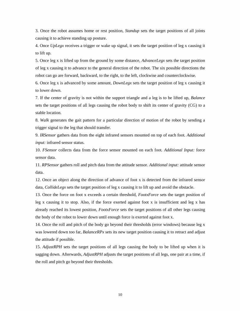
Fig. 11 illustrates side views of the quadruped climbing up and down the obstacle.
Figure 7. Foot elevations on a walking experiment
Figure 8. IR sensor responses on a walking experiment
Figure 9. Force sensor responses on a walking experiment
00 20 40 60 80 100 120 140 160 180 200 220 240 260 280 300 320 340
time (sec)
ir sensoron
foot 4
foot 3
foot 2
foot 1
0
12
24
36
48
0 20 40 60 80 100 120 140 160 180 200 220 240 260 280 300 320 340time (sec)
height of
foot 4
foot 3
foot 2
foot 1(cm)
0
40
80
120
160
0 20 40 60 80 100 120 140 160 180 200 220 240 260 280 300 320 340time (sec)
force on
foot 4
foot 3
foot 2
foot 1(force unit)

18
Figure 10. Roll and pitch sensor data on a walking experiment
The quadruped started with standing up posture at 0 sec. Looking at Fig. 7, leg 2 was the first one
selected for transfer. It was followed by legs 1, 3 and 4 in that sequence. Until after transferring
leg 2 for the second time, the quadruped was on the flat ground. But at 44.2 sec, foot 1
encountered an obstacle as can be seen in Fig. 8 plot of its ir sensors. Leg 1 was lifted up further
until the obstacle can no longer be seen. Afterwards, it continued moving forward. When it was
being placed down, foot 1 force sensor observed a sudden jump in its reading as seen in Fig. 9 at
47.2 sec where force reading changed from 0 to around 18 force units. Leg 1 was stopped and it
was retracted a bit because the roll and pitch exceeded the ±0.2° error window. After doing the
attitude adjustment, foot 1 settled on top of the obstacle as indicated by a higher value of its
height. It can be noticed that from the instant leg 1 was lifted up until it has been placed and
settled down again, there is a “valley” on the plot of force sensor reading. This “valley” is an
example of the duration of time when ir and force sensor readings on leg 1 (as well as the roll and
pitch reading) are valid.
Immediately after 60 sec when leg 4 was selected for transfer, foot 4 encountered an obstacle
as shown in Fig. 8. After foot 4 was placed down, the roll and pitch also exceeded the error
window, thus activating the attitude balancing behavior. It can be seen on Fig. 7 that both legs 3
and 4 were lowered down further with respect to the bottom part of the body frame to correct the
error.
Legs 3 and 2 (the two rear legs) encountered the same obstacle at 125.6 sec and 147.4 sec
respectively. After placing down foot 2 this time, the quadruped had already climbed up the
obstacle. However, it was only after 160 sec when leg 1 was lowered down that the robot realized
that its body height was below minimum. Body level readjustment was done at around 167.5 sec
as can be seen in Fig. 7. After this time, the robot walked again as if it was on the flat ground.
-8
-6
-4
-2
0
2
4
0 20 40 60 80 100 120 140 160 180 200 220 240 260 280 300 320 340
time (sec)
roll
pitch(degree)
19
Figure 11. Side views of the NUS quadruped climbing up and down the obstacle
obstacle
The NUS Quadruped
floor
1 423
0 sec
obstacle
The NUS Quadruped
floor
1
423
44+ sec
obstacle
The NUS Quadruped
floor
1423
60+ sec
obstaclefloor
The NUS Quadruped
1 423
160+ sec
obstaclefloor
The NUS Quadruped1 423
168+ sec
obstaclefloor
The NUS Quadruped
1423
197.5 sec
obstaclefloor
The NUS Quadruped
1
423
200+ sec
obstaclefloor
The NUS Quadruped
1 423
227+ sec
obstacle
floor
The NUS Quadruped
23
310+ sec
1 4
obstacle
The NUS Quadruped
floor
1 423
332+ sec

20
Since the obstacle is only 1 m wide, when the quadruped continued moving forward, it would
reach the end of its “new” flat ground. This happened at around 197.5 sec. As can be seen in Figs.
7 and 9, when foot 1 was lowered down no force was detected. The quadruped reached the lower
ground by retracting legs 2, 3 and 4. When the minimum force was already present against foot 1,
the robot continued walking. At time just after 226.8 sec, leg 4 was also placed to the lower
ground. Legs 3 and 2 followed at 309.3 sec and 331.8 sec respectively. After which, the
quadruped had already successfully descended the obstacle.
Looking back at Fig. 8 again, it can be noticed that there are extra spikes on ir sensor signal on
feet 1 and 4. For foot 1, the extra spike at 190.9 sec was due to edge of the obstacle as seen by the
back ir sensors. For foot 4, the extra spikes at 100.4, 137.6 and 221.7 sec were due to noise
generated by the bright sunlight entering our lab. The quadruped simply ignored these extra
spikes when they were verified as noise or not on the direction of motion. This is done by the
window filter of the IRSensor module. Knowing the current direction of the quadruped, the
IRSensor module considers three bits of the one-byte data only. The three bits correspond to the
three ir sensors facing the direction of motion of the quadruped. However, if the noise triggered
any of these three ir sensors, it can be considered a failure on the part of the IRSensor module. In
Fig. 9, it can be noticed that the foot 1 force sensor reading is lower after 200 sec while foot 2
force sensor reading is higher after 240 sec. The deviation in force sensor readings is due some
imbalance in force distribution on the four feet. It happens when the quadruped has just
maneuvered a wide obstacle. However, the force distribution on all feet can return to normal (of
nearly equal values) after few strides as can be seen on foot 2 foot sensor reading in Fig. 9 after
about 330 sec. In Fig. 10, any significant deviations in roll and pitch were corrected at once by
the controller. The attitude was maintained within the narrow band of error from its reference
value throughout the 2-m journey.
8.0 Conclusion
This paper proposes an architecture for robot control systems that allows both reactive and
deliberative controllers to be integrated and tested easily. The overall control system is composed
of different groups of controller performing different but related tasks. Each group can be a
collection of task-achieving modules of a reactive controller or it can be modules from the
knowledge-based controller sense-model-plan-act procedure. All modules pass messages through
a common communication line that is connected to the group’s job processor module (JPM). A

21
message contains some relevant information related to the group’s task. Each module in a group
cooperates or competes with one another to accomplish the task.
Our four-legged robot is currently using the proposed control architecture to run both the
behavior-based and the (simple) knowledge-based parts of its controller. With this control system,
the quadruped can walk on a structured uneven terrain with a simple navigational capability. To
enable the robot perform other tasks, the control system can be easily upgraded. For example,
foothold selection capability can be added by controlling how far a leg is advanced.
The proposed control architecture is a design approach that allows robot control systems
to be built, upgraded and maintained conveniently. A suitable type of controller for a certain task
can be determined easily since the platform is flexible. The modular approach, the common
communication line and a well-defined interface used result into a simple implementation and
representation of the overall control systems. Both single and multiprocessor implementations are
also possible.
References
[1] R. O. Atienza and M. H. Ang Jr., “A low-level control system of a four-legged robot using
fuzzy logic,” In Proc. of ISIAC ’98 2nd International. Symposium. on Intelligent Automation and
Control, Alaska, USA, May 1998.
[2] R. A. Brooks, “A robust layered control system for a mobile robot,” IEEE Journal of Robotics
and Automation, vol. 2, no. 1, pp. 14-23, 1986.
[3] R. A. Brooks, “A robot that walks: Emergent behaviors from a carefully evolved network,”
Neural Computation, vol. 1, no. 2, pp. 365-382, 1989.
[4] R. A. Brooks, “Intelligence without reason,” Proceedings of IJCAI-91, 1991.
[5] J. Connell, “SSS: A Hybrid Architecture Applied to Robot Navigation,” In Proc. of the IEEE
International Conference on Robotics and Automation, Los Alamitos, CA, USA, pp. 2719-2724,
1992.
[6] J. R. Firby, “Adaptive Execution in Complex Dynamic Worlds,” Technical Report
YALEU/CSD/RR #672, Computer Science Department, Yale University, 1989.
[7] E. Gat, “Integrating Planning and Reacting in a Heterogeneous Asynchronous Architecture for
Controlling Real-World Mobile Robots,” In Proc. of the Tenth National Conference on Artificial
Intelligence, Menlo Park, CA, USA: AAAI Press, 1992.
[8] P. Maes, “Behavior-based artificial intelligence,” Proceedings of the Second Conference on
Adaptive Behavior, MIT Press, 1993.

22
[9] R. B. McGhee and A. A. Frank, “On stability properties of quadruped creeping gaits,” Math.
Biosci., vol. 3, pp. 331-351, 1968.
[10] RTKernel Version 4.5 Manual.
[11] R. G. Simmons, “Structured control for autonomous robots,” IEEE Transactions on
Robotics and Automation, vol. 10, no. 1, 1994.
[12] D. Wettergreen and C. Thorpe, “Gait generation for legged robots,” IEEE International
Conference on Intelligent Robots and Systems, July, 1992.
[13] D. Wettergreen, C. Thorpe and R. Whittaker, “Exploring Mount Erebus by walking robot,”
Robotics and Autonomous Systems, vol. 11, pp. 171-185, 1993.
[14] D. Wettergreen, H. Pangels and J. Bares, “Behavior-based gait execution for the Dante II
walking robot,” International Conference on Intelligent Robots and Systems, pp. 274-279, August
1995.
[15] D. Wettergreen and C. Thorpe, “Developing planning and reactive control for a hexapod
robot,” In Proc. of the 1996 IEEE International Conference on Robotics and Automation, pp.
2718-2723, 1996.


