Depth Selective Camera: A Direct, On-chip, Programmable Technique for Depth
Selectivity in Photography
Ryuichi Tadano
Sony Corporation
Tokyo, Japan
Adithya Kumar Pediredla, Ashok Veeraraghavan
Rice University
Houston, TX, USA
[adithya.k.pediredla, vashok] @rice.edu
Abstract
Time of flight (ToF) cameras use a temporally modu-
lated light source and measure correlation between the re-
flected light and a sensor modulation pattern, in order to
infer scene depth. In this paper, we show that such cor-
relational sensors can also be used to selectively accept or
reject light rays from certain scene depths. The basic idea is
to carefully select illumination and sensor modulation pat-
terns such that the correlation is non-zero only in the se-
lected depth range – thus light reflected from objects outside
this depth range do not affect the correlational measure-
ments. We demonstrate a prototype depth-selective camera
and highlight two potential applications: imaging through
scattering media and virtual blue screening. This depth-
selectivity can be used to reject back-scattering and reflec-
tion from media in front of the subjects of interest, thereby
significantly enhancing the ability to image through scatter-
ing media- critical for applications such as car navigation
in fog and rain. Similarly, such depth selectivity can also
be utilized as a virtual blue-screen in cinematography by
rejecting light reflecting from background, while selectively
retaining light contributions from the foreground subject.
1. Introduction
Time of flight (ToF) cameras, which acquire a three-
dimensional (3D) representation of a scene based on the
travel time of illuminating photons, have come of age over
the last several years and are poised to revolutionize imag-
ing capabilities. A ToF camera consists of a modulated
light source and a specialized image sensor that correlates
the waveform received from the scene with the modulation
function in order to estimate the amount of time taken, and
hence the depth, for light to travel.
ToF cameras provide unique benefits over competing 3D
scene acquisition technologies. They do not require the
computation of image/feature correspondences, an element
of both multi-view and structured light techniques. They
also do not require a complicated scanning mechanism as
in LIDAR systems. Most importantly, ToF sensors can be
fabricated using traditional CMOS fabrication techniques,
thereby benefiting enormously from the scaling, cost and
efficiency advantages offered through the advances in semi-
conductor fabrication techniques.
The inexpensive ToF cameras, such as the Kinect from
Microsoft, the CamBoard from PMD Technologies, and
Swissranger from MESA imaging has revolutionized a
range of consumer imaging applications. The 3D imaging
capability offered by these sensors has enabled a new era of
untethered and unconstrained game play in modern video
gaming consoles [4, 23]. In addition, the environment sens-
ing capabilities of these devices makes many head-mounted
augmented, virtual and mixed reality [14] applications re-
alistic and perceptually engaging, without the physiological
discomfort associated with previous generation systems that
were constrained by the effect of small errors in range and
ego motion estimation. Much of the work in ToF sensors
and their potential applications have focussed solely on the
3D imaging capabilities provided by these sensors.
Correlational Sensors for 2D Imaging: We explore an in-
teresting alternate question. Can these modern ToF sensors
that exploit active illumination and correlational sensors be
used to enhance the capabilities of 2D imaging and photog-
raphy? In this paper, we address two important limitations
of traditional photography, (a) imaging in scattering media
and (b) accurate segmentation of foreground objects for vir-
tual blue-screening. We show that while these two limita-
tions are seemingly unrelated, they both stem from the same
fundamental handicap that plagues traditional imaging: the
inability to reject contributions from photons that are not
from the desired depth range. We show that careful de-
sign of the illumination and the sensor codes in correlational
sensors will allow us to accept light contributions from a
user-controlled, selective, programmable depth range while
rejecting all other light. Such depth selectivity may poten-
tially lead to a wide range of imaging and photography ap-
plications hitherto not possible as shown in figure 1.
Technical Contributions:
• Enhance 2D imaging using correlational sensors: We
13595
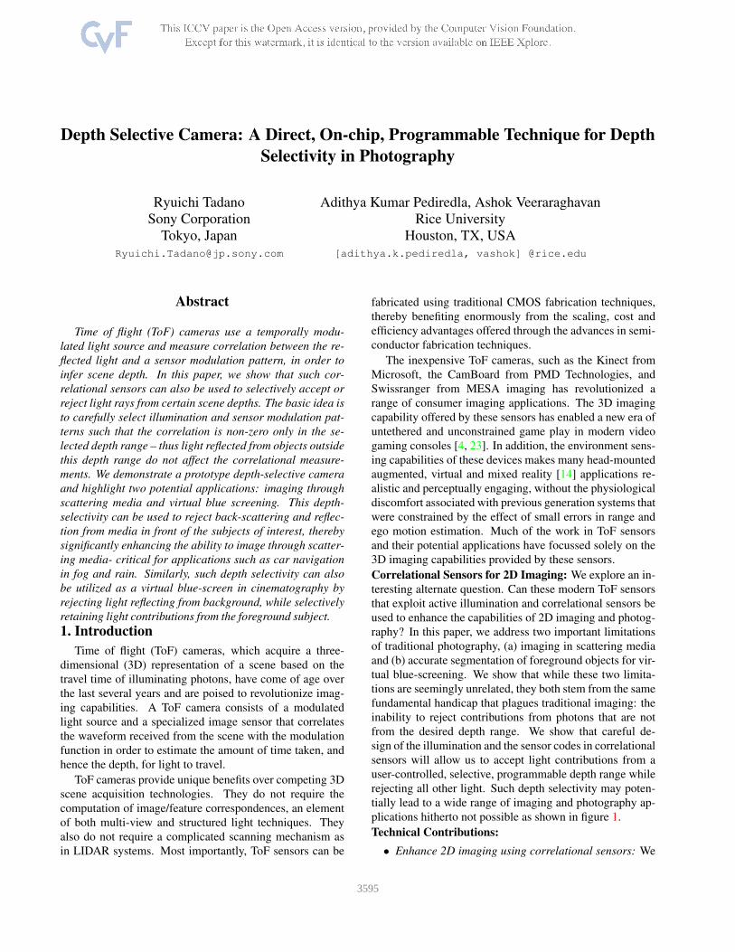
Normal camera
Sensitivity
Depth
Our camera
Normal camera
Sensitivity
Depth
Our camera
Figure 1. Two example applications of Depth Selective Camera. In our system, we can selectively image objects of interest by controlling
the depth sensitivity of the camera. (Left) The sensitivity is designed to suppress the backward reflection from scattering media. (Right)
Unwanted objects behind the subject are suppressed. In the plot on the bottom, blue line shows the sensitivity of our camera and red line
shows the sensitivity of normal camera.
show that proper design of illumination and sensor
codes in correlational sensors can overcome some lim-
its of traditional 2D imaging.
• Depth Selective Camera: We show careful design
of the illumination and the sensor codes in correla-
tional sensors will allow us to accept light contribu-
tions from a user-controlled, selective, programmable
depth range while rejecting light contributions from
outside this range. In addition, we demonstrate tech-
niques to sharpen the range of interest beyond the limit
imposed by the modulation frequency, by using multi-
ple image captures with different codes.
• Back-scatter resistant photography: We demonstrate
back-scatter resistant photography using our camera
and demonstrate several examples where back-scatter
from occluders is rejected increasing the range of
imaging in highly scattering environments.
• Virtual blue-screening: We demonstrate that such
depth-selective cameras can be used for virtual blue-
screening in teleconference and other applications,
since it provides an effective means to segment the
subject from its background without the need for any
color or texture information.
Limitations:
• Decrease in Light efficiency: As the proposed tech-
nique rejects light contributions outside the selected
range, it suffers from a decrease in light efficiency and
consequently SNR.
• Pixel saturation: Higher light intensities can saturate
the PMD sensor resulting in wrong cross-correlation
value and hence, the depth selection. However, in
some specific cases especially in indoor scenes (like
our experiments), the dynamic range of the PMD sen-
sor is good enough.
• Limited range precision: The precision of range selec-
tion we can achieve is limited by the peak modulation
frequency of the light source and PMD sensor.
• Spatial Resolution: The spatial resolution of the sensor
we use in our experiments is 160×120 pixels, resulting
in low resolution images. Over the last few years there
is an explosion of work in ToF sensors and higher reso-
lution ToF sensors are slowly entering the mainstream
(Kinect 2.0 is a 640×480 sensor). The current low res-
olution images can be improved with the use of these
and other higher resolution ToF sensors.
2. Related work
In this section, we compare our camera with state-of-the-
art techniques employed for imaging in scattering media.
Gated imaging: Many applications such as automobile
night vision and safety [9, 11], surveillance system [22, 27,
3], long distance identification [1], and mammography [8]
use gated imaging for selective range imaging.
In gated imaging system, a short pulsed laser light is
emitted and a synchronized super high speed shutter in the
camera is opened for a brief duration to allow light reflected
back only from the range of interest. These systems suf-
fer from poor light efficiency just like the proposed camera.
However, these cameras are not robust to ambient light and
also suffer from interference problems. On the contrast, the
PMD sensor in our camera subtracts the ambient light mak-
ing it a more robust solution compared to gated imaging. In
addition, single pulsed operation requires heat management
of light source as large currents are needed to create suffi-
cient amount of light for low duty pulsed light emission.
Adaptive illumination: Tamburo et al. [24] have built a
programmable automotive headlight system to increase the
visibility during rain or snow. Their system first estimates
the location of rain drops or snow flakes by detecting their
motion. The illumination pattern of the programmable pro-
jector is adapted to carefully avoid these rain drops or snow
flakes. This decreases the back scatter of the light, increas-
ing the visibility range. The main draw back of their system
is its inability to handle a homogeneous scattering medium
such as fog. On the contrast, our technique is impervious to
the nature of the scattering medium.
Post processing: To remove rain drops in a video, a com-
prehensive model for the visual appearance of rain was pro-
posed by Garg and Nayar [10]. They took advantage of the
3596
temporal information in both detecting and removing rain
drops. Barnum et al. [2] utilized spatial-temporal frequency
information to detect and remove rain and snow in captured
videos. These techniques strongly rely on a specific model
of rain or snow and cannot handle scenes having fog or mist.
To remove the effect of haze from captured images,
Schechner et al. [19] introduced a method based on polar-
ization effect of atmospheric scattering. Shwartz et al. [21]
proposed a blind estimation method for separating the light
(haze component) from measurement. He et al. [12] pro-
posed dark channel prior, to recover haze-less image. None
of these techniques can suppress the backward reflection
from haze.
Time of Flight Camera: Kadambi et al. [15] employed
pseudo random code both for illumination and reference
signal of a ToF camera. Using such a setup, they were
able to do transient imaging, ranging of transparent objects,
looking through diffuse materials, and increasing the ac-
curacy of depth maps. Though the application of looking
through diffuse materials is similar to our technique, our
method is based on straight forward cross correlation de-
sign and can be done with only one measurement.
Heide et al. [13] also unveiled subjects sinked in scat-
tering medium. They proposed a modified exponential
reflection model that describes the impulse response of
light reflection from a scattering medium. However, their
method requires hundreds of measurements at different
phases/frequencies of sinusoidal wave. Thus, their method
cannot be applied to real time applications.
Primal-Dual Coding: The goal of our technique is direct
on-chip suppression of light from regions outside the se-
lected depth range. Conceptually our work is similar to
primal-dual coding for direct on-chip direct-only imaging.
O’Toole et al. [18] present a technique that uses a spatio-
temporal modulator as a projector to illuminate the scene
and synchronously modulate the exposure duration of each
pixel in the sensor. By carefully selecting the spatial-codes
on the projector and the sensor, one can ensure that only di-
rect paths contribute to the sensor measurements while indi-
rect light does not affect the sensor measurements. Unlike
primal dual coding which requires a spatio-temporal cod-
ing both on the illumination and on the sensor, we require
only temporal modulation both on the illumination and the
sensor, resulting in much simpler hardware requirements.
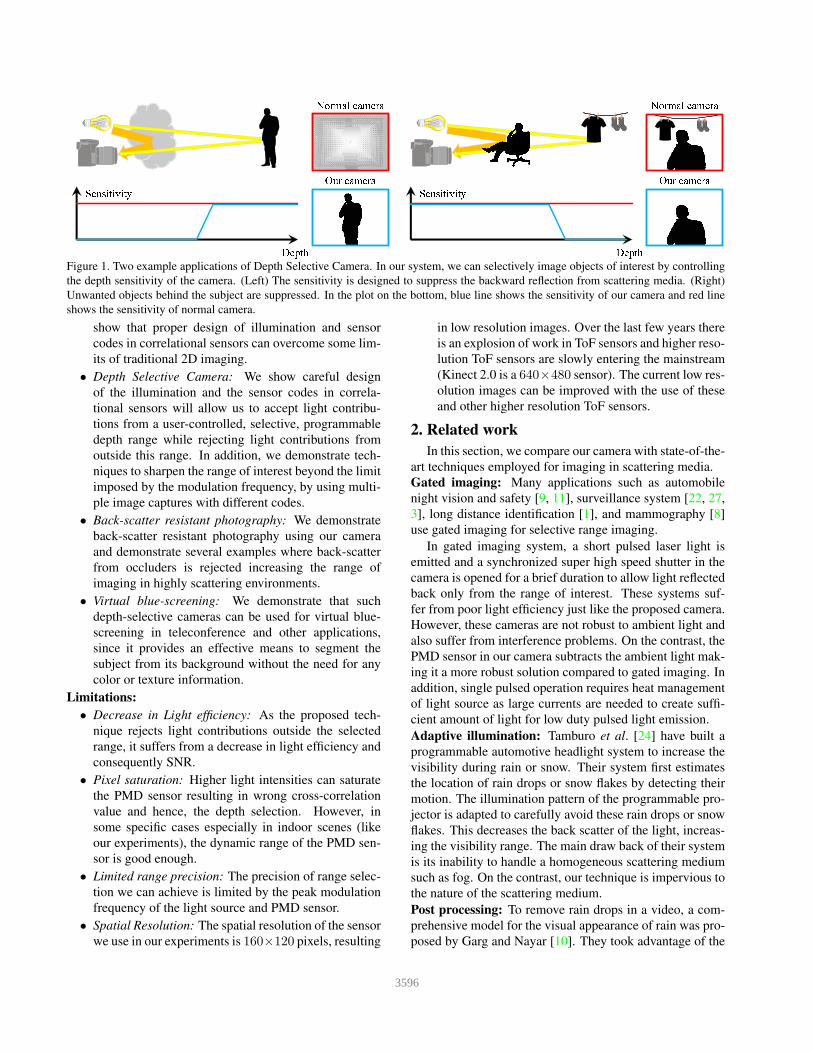
3. Temporal coding in illumination and sensor
We will explain the principles of Photon Mixer Device
(PMD) sensor based ToF camera and proceed to our design
of a depth selective camera. ToF camera [25, 17, 16, 20, 7]
consists of a light source that emits coded illumination
(g(t)). As illustrated in figure 2, the illumination signal
from the light source g(t) hits the object surface, gets scat-
tered and reaches the sensor pixel with a delay τ due to the
finite speed of light. The received signal can be given as
illumination
reference signal
illumination code
object
lens
Controller
PMD sensor
Figure 2. ToF camera system. The system controller sends two
binary signals: reference signal f(t) to the PMD sensor and illu-
mination code g(t) to the light source. For each pixel, the PMD
sensor measures correlation between the reference signal and inci-
dent light coming to the sensor.
βg(t − τ), where β represents the albedo of that particular
scene pixel. The PMD sensor calculates the cross corre-
lation between a reference signal (f(t)) and received signal
βg(t−τ). This process is repeated for different phase shifts
φ between the coded illumination and the reference signal,
and these multiple measurements bi(φ). The output of PMD
sensor at each pixel is given by
bi(φ) =
∫
∞
0
αi(τ) ·
∫ T
0
βg(t+ φ− τ)f(t) dt dτ, (1)
where αi(τ) =∫
pαi,pδ(|p| = τ) dp is attenuation coef-
ficient that is uniquely determined by the path traveled by
light, T is exposure time, and φ is phase offset for g(t). The
attenuation coefficient αi(τ), accounts for the d2 propoga-
tion loss of light intensity: without this attenuation com-
pensation the intensity (albedo: β) of objects farther away
will be under-estimated, though their depth would still be
correctly estimated.
In ToF camera used in Kinect to capture depth informa-
tion, f(t) and g(t) are both sinusoidal waves. The frequen-
cies of both the signals are usually the same. Three or four
measurements with different amounts of phase shift are re-
quired to generate depth information. When multiple cam-
eras are in operation, custom code such as pseudo random
sequence can be utilized as in [5, 26] so as to avoid interfer-
ence between the cameras.
4. Range selection via cross correlation design
Given that the sensor measurements can be given as the
cross-correlation between illumination codes g(t) and sen-
sor codes f(t), one can control the depth-selectivity prop-
erties of such a measurement by appropriately designing il-
lumination and sensor codes.
General Problem Definition: In this section, we pro-
pose a Depth Selectivity camera based on ToF technol-
ogy. We pose it as the problem of designing the illumi-
nation signal g(t) and reference signal f(t) such that the
cross-correlation provides the desired depth selectivity. In
3597
general, lets assume that we would like to acquire an im-
age with an arbitrary depth-dependent attenuation function
γ(τ): i.e., given a scene with albedo β(x, y) and depth-
map z(x, y), we would like to directly acquire an image
I(x, y) = γ(τz(x,y))β(x, y). Without loss of generality, lets
drop the pixel identifier (x, y) since all operations are per-
formed independently at each pixel. Mathematically,
find f and g such that:∫ T
0
g(t+ φ− τ)f(t) dt = γ(τ); f(t), g(t) ∈ Z. (2)
i.e., find codes f and g such that their cross-correlation is
the desired depth-dependent attenuation function γ. Rewrit-
ing the above problem statement as minimization problem,
{f, g} = argminf, g
(
∫ T
0
g(t+ φ− τ)f(t) dt− γ(τ)
)2
such that: f(t), g(t) ∈ Z. (3)
The discrete version of the optimization problem in equa-
tion 3 has the same constraints of the integer programming
problem and further, the cost function is quadratic in both f
and g. Hence, the optimization problem is NP-hard and we
resort to heuristics to solve equation 3.
4.1. Code design
In this section, we describe a heuristic to design illu-
mination signal g and reference signal f that minimizes
the cost function in equation 3 with out violating the de-
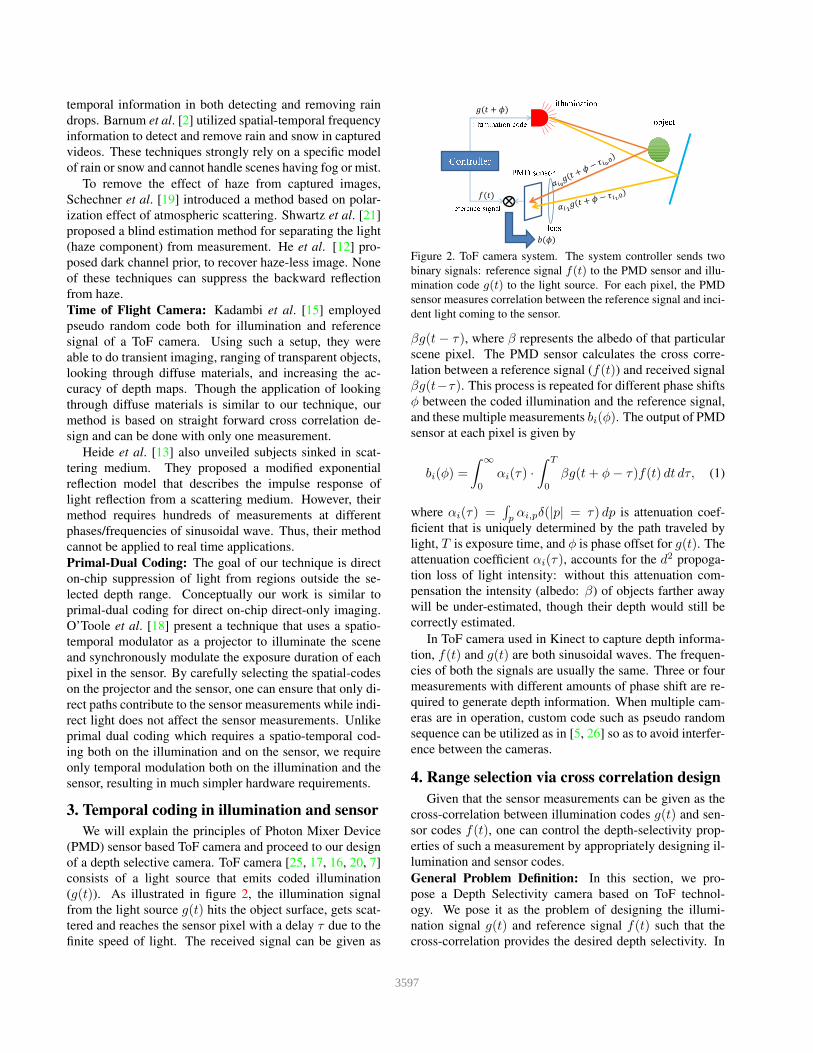
sign constraints. We use m-sequences [6] that have trian-
gle shaped auto correlation as shown in figure 3 as basis
for code design. The horizontal axis “shift amount” corre-
sponds to the distance light travels. This means that when
we send the same m-sequence as f(t) and g(t) in equation
1, only the objects whose distance correspond to the peaks
in this cross correlation can be seen. The interval between
the peaks is controlled by the bit length of the m-sequence.
We design a code with desired cross correlation func-
tion by superimposing phase shifted m-sequences. We can
implement the superimposition by re-writing either f(t) or
g(t) as a linear combination of shifted versions of the other
code and using m-sequence for the other code. For example,
if we superimpose f(t) to get g(t), we have:
f(t) =∑
i
βig(t+ φi). (4)
By controlling βi, we can separate the scene into layers
based on the depth and observe them independently. These
layers allow us to recreate arbitrary range of interest just by
stacking them (see figure 4).
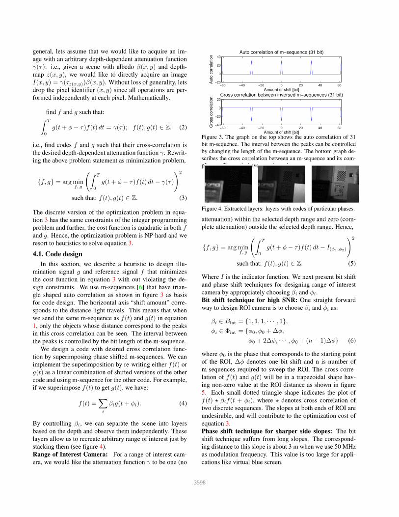
Range of Interest Camera: For a range of interest cam-
era, we would like the attenuation function γ to be one (no
−60 −40 −20 0 20 40 60−20
0
20
40
Auto correlation of m−sequence (31 bit)
Amount of shift [bit]
Auto
corr
ela
tion
−60 −40 −20 0 20 40 60−40
−20
0
20
Cross correlation between inversed m−sequences (31 bit)
Amount of shift [bit]
Cro
ss c
orr
ela
tion
Figure 3. The graph on the top shows the auto correlation of 31
bit m-sequence. The interval between the peaks can be controlled
by changing the length of the m-sequence. The bottom graph de-
scribes the cross correlation between an m-sequence and its com-
pliment. The peaks have negative value.
Figure 4. Extracted layers: layers with codes of particular phases.
attenuation) within the selected depth range and zero (com-
plete attenuation) outside the selected depth range. Hence,
{f, g} = argminf, g
(
∫ T
0
g(t+ φ− τ)f(t) dt− I(φ1,φ2)
)2
such that: f(t), g(t) ∈ Z. (5)
Where I is the indicator function. We next present bit shift
and phase shift techniques for designing range of interest
camera by appropriately choosing βi and φi.
Bit shift technique for high SNR: One straight forward
way to design ROI camera is to choose βi and φi as:
βi ∈ Bint = {1, 1, 1, · · · , 1},
φi ∈ Φint = {φ0, φ0 +∆φ,
φ0 + 2∆φ, · · · , φ0 + (n− 1)∆φ} (6)
where φ0 is the phase that corresponds to the starting point
of the ROI, ∆φ denotes one bit shift and n is number of
m-sequences required to sweep the ROI. The cross corre-
lation of f(t) and g(t) will be in a trapezoidal shape hav-
ing non-zero value at the ROI distance as shown in figure
5. Each small dotted triangle shape indicates the plot of
f(t) ⋆ βif(t + φi), where ⋆ denotes cross correlation of
two discrete sequences. The slopes at both ends of ROI are
undesirable, and will contribute to the optimization cost of
equation 3.
Phase shift technique for sharper side slopes: The bit
shift technique suffers from long slopes. The correspond-
ing distance to this slope is about 3 m when we use 50 MHz
as modulation frequency. This value is too large for appli-
cations like virtual blue screen.
3598
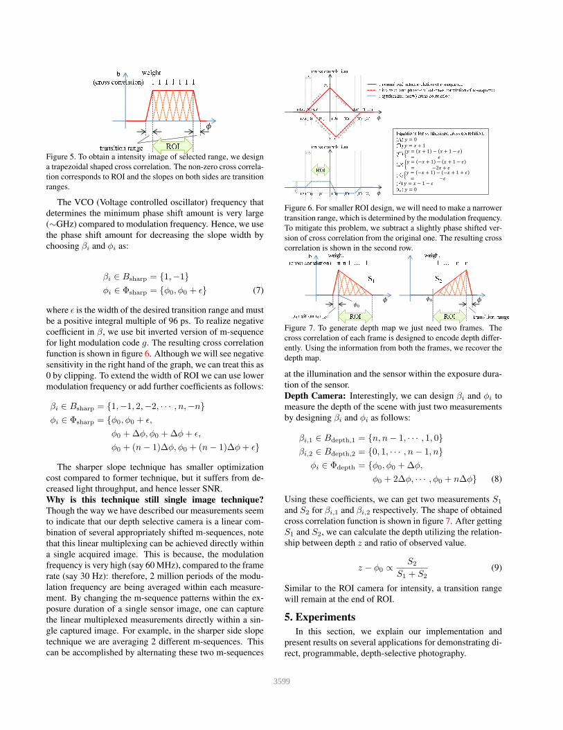
b
(cross correlation)
transition range
1 1 1 11 1 1
weight
ROI
Figure 5. To obtain a intensity image of selected range, we design
a trapezoidal shaped cross correlation. The non-zero cross correla-
tion corresponds to ROI and the slopes on both sides are transition
ranges.
The VCO (Voltage controlled oscillator) frequency that
determines the minimum phase shift amount is very large
(∼GHz) compared to modulation frequency. Hence, we use
the phase shift amount for decreasing the slope width by
choosing βi and φi as:
βi ∈ Bsharp = {1,−1}
φi ∈ Φsharp = {φ0, φ0 + ǫ} (7)
where ǫ is the width of the desired transition range and must
be a positive integral multiple of 96 ps. To realize negative
coefficient in β, we use bit inverted version of m-sequence
for light modulation code g. The resulting cross correlation
function is shown in figure 6. Although we will see negative
sensitivity in the right hand of the graph, we can treat this as
0 by clipping. To extend the width of ROI we can use lower
modulation frequency or add further coefficients as follows:
βi ∈ Bsharp = {1,−1, 2,−2, · · · , n,−n}
φi ∈ Φsharp = {φ0, φ0 + ǫ,
φ0 +∆φ, φ0 +∆φ+ ǫ,
φ0 + (n− 1)∆φ, φ0 + (n− 1)∆φ+ ǫ}
The sharper slope technique has smaller optimization
cost compared to former technique, but it suffers from de-
creased light throughput, and hence lesser SNR.
Why is this technique still single image technique?
Though the way we have described our measurements seem
to indicate that our depth selective camera is a linear com-
bination of several appropriately shifted m-sequences, note
that this linear multiplexing can be achieved directly within
a single acquired image. This is because, the modulation
frequency is very high (say 60 MHz), compared to the frame
rate (say 30 Hz): therefore, 2 million periods of the modu-
lation frequency are being averaged within each measure-
ment. By changing the m-sequence patterns within the ex-
posure duration of a single sensor image, one can capture
the linear multiplexed measurements directly within a sin-
gle captured image. For example, in the sharper side slope
technique we are averaging 2 different m-sequences. This
can be accomplished by alternating these two m-sequences
(A) (B) (C) (D) (E) (F)
(0,1)
(-1,0) (-1+ε,0)
(ε,1)
(1,0) (1+ε,1)
ε
(G)
(A) (B) (C) (D) (E) (F)
ε
(G)
ε
ε
: normalized autocorrelation of m-sequence
: inversed and phase-shifted cross correlation of m-sequence
: synthesized (new) cross correlation
Equations for synthesized cross correlation:
(A)
(B)
(C)
(D)
(E)
(F)
(G)
cross correlation
cross correlation
ROI
Figure 6. For smaller ROI design, we will need to make a narrower
transition range, which is determined by the modulation frequency.
To mitigate this problem, we subtract a slightly phase shifted ver-
sion of cross correlation from the original one. The resulting cross
correlation is shown in the second row.b
(cross correlation)
transition range
n n-1 … 1
transition range
n… n-11
S
1
S
2
weight weight
ROI ROI
Figure 7. To generate depth map we just need two frames. The
cross correlation of each frame is designed to encode depth differ-
ently. Using the information from both the frames, we recover the
depth map.
at the illumination and the sensor within the exposure dura-
tion of the sensor.
Depth Camera: Interestingly, we can design βi and φi to
measure the depth of the scene with just two measurements
by designing βi and φi as follows:
βi,1 ∈ Bdepth,1 = {n, n− 1, · · · , 1, 0}
βi,2 ∈ Bdepth,2 = {0, 1, · · · , n− 1, n}
φi ∈ Φdepth = {φ0, φ0 +∆φ,
φ0 + 2∆φ, · · · , φ0 + n∆φ} (8)
Using these coefficients, we can get two measurements S1
and S2 for βi,1 and βi,2 respectively. The shape of obtained
cross correlation function is shown in figure 7. After getting
S1 and S2, we can calculate the depth utilizing the relation-
ship between depth z and ratio of observed value.
z − φ0 ∝S2
S1 + S2(9)
Similar to the ROI camera for intensity, a transition range
will remain at the end of ROI.
5. Experiments
In this section, we explain our implementation and
present results on several applications for demonstrating di-
rect, programmable, depth-selective photography.
3599
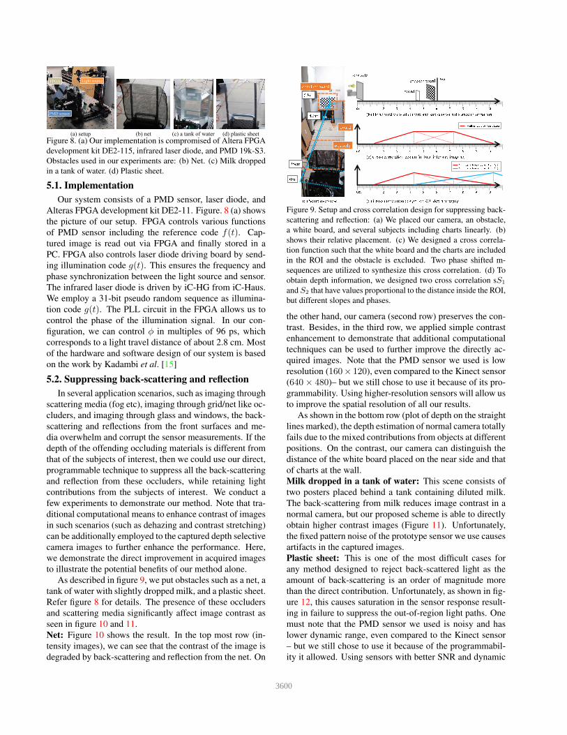
PMD sensor
Light sourceFPGA
(b) net (d) plastic sheet(c) a tank of water(a) setup
Figure 8. (a) Our implementation is compromised of Altera FPGA
development kit DE2-115, infrared laser diode, and PMD 19k-S3.
Obstacles used in our experiments are: (b) Net. (c) Milk dropped
in a tank of water. (d) Plastic sheet.
5.1. Implementation
Our system consists of a PMD sensor, laser diode, and
Alteras FPGA development kit DE2-11. Figure. 8 (a) shows
the picture of our setup. FPGA controls various functions
of PMD sensor including the reference code f(t). Cap-
tured image is read out via FPGA and finally stored in a
PC. FPGA also controls laser diode driving board by send-
ing illumination code g(t). This ensures the frequency and
phase synchronization between the light source and sensor.
The infrared laser diode is driven by iC-HG from iC-Haus.
We employ a 31-bit pseudo random sequence as illumina-
tion code g(t). The PLL circuit in the FPGA allows us to
control the phase of the illumination signal. In our con-
figuration, we can control φ in multiples of 96 ps, which
corresponds to a light travel distance of about 2.8 cm. Most
of the hardware and software design of our system is based
on the work by Kadambi et al. [15]
5.2. Suppressing backscattering and reflection
In several application scenarios, such as imaging through
scattering media (fog etc), imaging through grid/net like oc-
cluders, and imaging through glass and windows, the back-
scattering and reflections from the front surfaces and me-
dia overwhelm and corrupt the sensor measurements. If the
depth of the offending occluding materials is different from
that of the subjects of interest, then we could use our direct,
programmable technique to suppress all the back-scattering
and reflection from these occluders, while retaining light
contributions from the subjects of interest. We conduct a
few experiments to demonstrate our method. Note that tra-
ditional computational means to enhance contrast of images
in such scenarios (such as dehazing and contrast stretching)
can be additionally employed to the captured depth selective
camera images to further enhance the performance. Here,
we demonstrate the direct improvement in acquired images
to illustrate the potential benefits of our method alone.
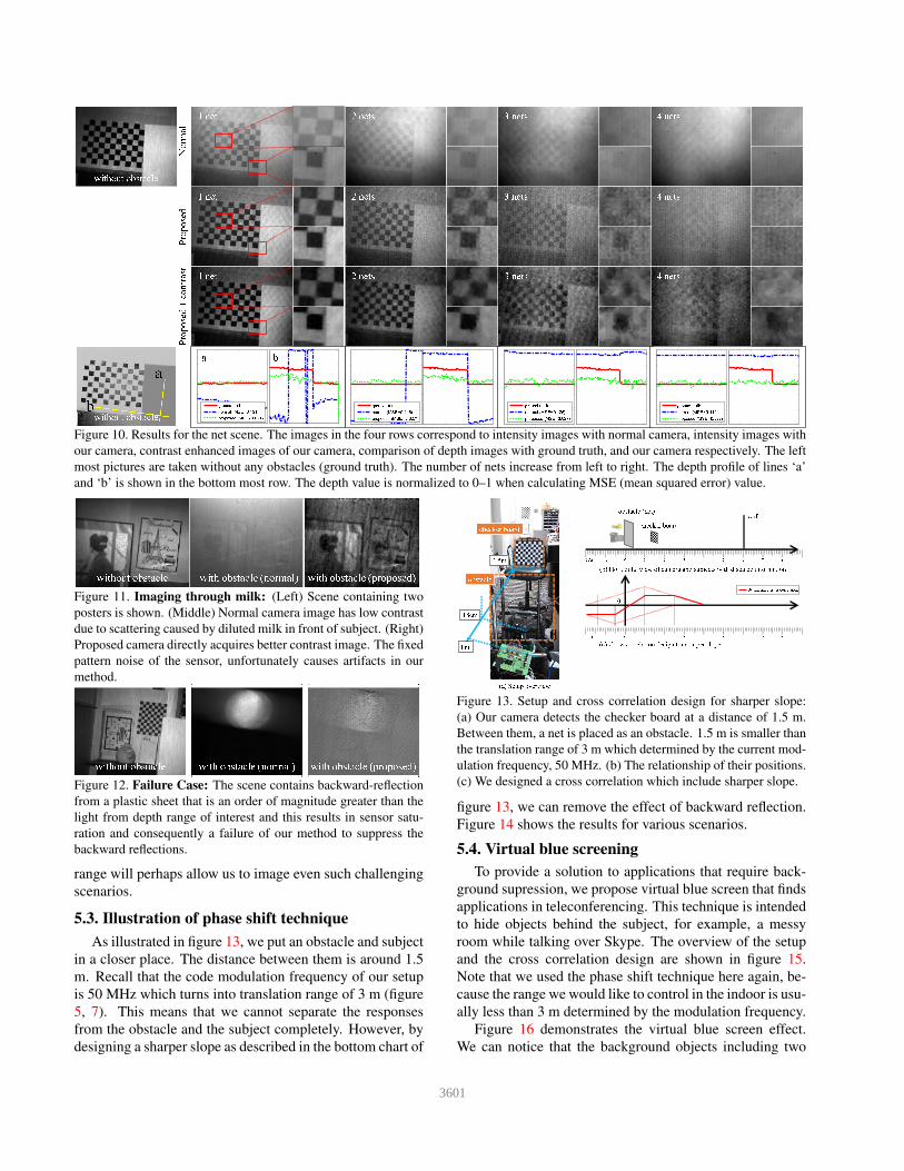
As described in figure 9, we put obstacles such as a net, a
tank of water with slightly dropped milk, and a plastic sheet.
Refer figure 8 for details. The presence of these occluders
and scattering media significantly affect image contrast as
seen in figure 10 and 11.
Net: Figure 10 shows the result. In the top most row (in-
tensity images), we can see that the contrast of the image is
degraded by back-scattering and reflection from the net. On
0m
35cm
5.8m
4.6m
board
obstacle
obstacle
board
checker board
8 9 106 70 1 2 3 4 5
8 9 106 70 1 2 3 4 5
8 9 106 70 1 2 3 4 5
m
m
m
wall
Synthesized cross correlation
Synthesized cross correlation (S
1
)
Synthesized cross correlation (S
2
)
(a) Setup overview
(b) Horizontal view of camera and subjects with distance information
(c) Cross correlation design for ROI intensity imaging
(d) Cross correlation design for ROI depth imaging
checker board
Figure 9. Setup and cross correlation design for suppressing back-
scattering and reflection: (a) We placed our camera, an obstacle,
a white board, and several subjects including charts linearly. (b)
shows their relative placement. (c) We designed a cross correla-
tion function such that the white board and the charts are included
in the ROI and the obstacle is excluded. Two phase shifted m-
sequences are utilized to synthesize this cross correlation. (d) To
obtain depth information, we designed two cross correlation sS1
and S2 that have values proportional to the distance inside the ROI,
but different slopes and phases.
the other hand, our camera (second row) preserves the con-
trast. Besides, in the third row, we applied simple contrast
enhancement to demonstrate that additional computational
techniques can be used to further improve the directly ac-
quired images. Note that the PMD sensor we used is low
resolution (160× 120), even compared to the Kinect sensor
(640× 480)– but we still chose to use it because of its pro-
grammability. Using higher-resolution sensors will allow us
to improve the spatial resolution of all our results.
As shown in the bottom row (plot of depth on the straight
lines marked), the depth estimation of normal camera totally
fails due to the mixed contributions from objects at different
positions. On the contrast, our camera can distinguish the
distance of the white board placed on the near side and that
of charts at the wall.
Milk dropped in a tank of water: This scene consists of
two posters placed behind a tank containing diluted milk.
The back-scattering from milk reduces image contrast in a
normal camera, but our proposed scheme is able to directly
obtain higher contrast images (Figure 11). Unfortunately,
the fixed pattern noise of the prototype sensor we use causes
artifacts in the captured images.
Plastic sheet: This is one of the most difficult cases for
any method designed to reject back-scattered light as the
amount of back-scattering is an order of magnitude more
than the direct contribution. Unfortunately, as shown in fig-
ure 12, this causes saturation in the sensor response result-
ing in failure to suppress the out-of-region light paths. One
must note that the PMD sensor we used is noisy and has
lower dynamic range, even compared to the Kinect sensor
– but we still chose to use it because of the programmabil-
ity it allowed. Using sensors with better SNR and dynamic
3600
without obstacle
1 net 2 nets 3 nets 4 nets
1 net 2 nets 3 nets 4 nets
1 net 2 nets 3 nets 4 nets
N
o
r
m
a
l
P
r
o
p
o
s
e
d
P
r
o
p
o
s
e
d
+
c
o
n
t
r
a
s
t
without obstacle
ground truth
normal (MSE=0.191)
proposed (MSE=0.021)
a
b
a
ground truth
normal (MSE=0.145)
proposed (MSE=0.027)
ground truth
normal (MSE=0.125)
proposed (MSE=0.027)
ground truth
normal (MSE=0.114)
proposed (MSE=0.033)
b
Figure 10. Results for the net scene. The images in the four rows correspond to intensity images with normal camera, intensity images with
our camera, contrast enhanced images of our camera, comparison of depth images with ground truth, and our camera respectively. The left
most pictures are taken without any obstacles (ground truth). The number of nets increase from left to right. The depth profile of lines ‘a’
and ‘b’ is shown in the bottom most row. The depth value is normalized to 0–1 when calculating MSE (mean squared error) value.
with obstacle (normal) with obstacle (proposed)without obstacle
Figure 11. Imaging through milk: (Left) Scene containing two
posters is shown. (Middle) Normal camera image has low contrast
due to scattering caused by diluted milk in front of subject. (Right)
Proposed camera directly acquires better contrast image. The fixed
pattern noise of the sensor, unfortunately causes artifacts in our
method.
with obstacle (normal) with obstacle (proposed)without obstacle
Figure 12. Failure Case: The scene contains backward-reflection
from a plastic sheet that is an order of magnitude greater than the
light from depth range of interest and this results in sensor satu-
ration and consequently a failure of our method to suppress the
backward reflections.
range will perhaps allow us to image even such challenging
scenarios.
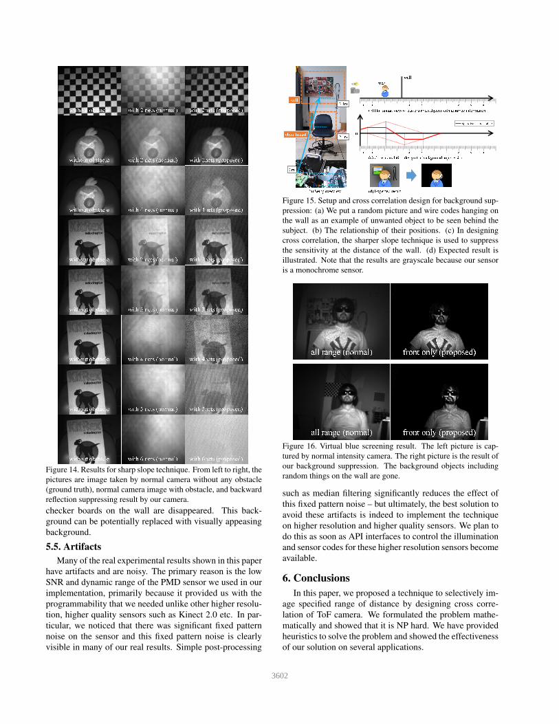
5.3. Illustration of phase shift technique
As illustrated in figure 13, we put an obstacle and subject
in a closer place. The distance between them is around 1.5
m. Recall that the code modulation frequency of our setup
is 50 MHz which turns into translation range of 3 m (figure
5, 7). This means that we cannot separate the responses
from the obstacle and the subject completely. However, by
designing a sharper slope as described in the bottom chart of
1.5m
checker board
(a) Setup overview
obstacle (net)
wall
Synthesized cross correlation
(b) Horizontal view of camera and subjects with distance information
(c) Cross correlation design for sharper slope
0
18cm
obstacle
0m
checker board
-1-2 4 5 6 7 80 1 2 3m
-1-2 4 5 6 7 80 1 2 3m
Figure 13. Setup and cross correlation design for sharper slope:
(a) Our camera detects the checker board at a distance of 1.5 m.
Between them, a net is placed as an obstacle. 1.5 m is smaller than
the translation range of 3 m which determined by the current mod-
ulation frequency, 50 MHz. (b) The relationship of their positions.
(c) We designed a cross correlation which include sharper slope.
figure 13, we can remove the effect of backward reflection.
Figure 14 shows the results for various scenarios.
5.4. Virtual blue screening
To provide a solution to applications that require back-
ground supression, we propose virtual blue screen that finds
applications in teleconferencing. This technique is intended
to hide objects behind the subject, for example, a messy
room while talking over Skype. The overview of the setup
and the cross correlation design are shown in figure 15.
Note that we used the phase shift technique here again, be-
cause the range we would like to control in the indoor is usu-
ally less than 3 m determined by the modulation frequency.
Figure 16 demonstrates the virtual blue screen effect.
We can notice that the background objects including two
3601
without obstacle with 2 nets (normal) with 2nets (proposed)
without obstacle with 2 nets (normal) with 2nets (proposed)
without obstacle with 4 nets (normal) with 4nets (proposed)
without obstacle with 3 nets (normal) with 3nets (proposed)
without obstacle with 2 nets (normal) with 2nets (proposed)
without obstacle with 4 nets (normal) with 4nets (proposed)
without obstacle with 5 nets (normal) with 5nets (proposed)
without obstacle with 6 nets (normal) with 6nets (proposed)
Figure 14. Results for sharp slope technique. From left to right, the
pictures are image taken by normal camera without any obstacle
(ground truth), normal camera image with obstacle, and backward
reflection suppressing result by our camera.
checker boards on the wall are disappeared. This back-
ground can be potentially replaced with visually appeasing
background.
5.5. Artifacts
Many of the real experimental results shown in this paper
have artifacts and are noisy. The primary reason is the low
SNR and dynamic range of the PMD sensor we used in our
implementation, primarily because it provided us with the
programmability that we needed unlike other higher resolu-
tion, higher quality sensors such as Kinect 2.0 etc. In par-
ticular, we noticed that there was significant fixed pattern
noise on the sensor and this fixed pattern noise is clearly
visible in many of our real results. Simple post-processing
8 9 106 70 1 2 3 4 5
8 9 106 70 1 2 3 4 5
m
m
wall
Synthesized cross correlation
(a) Setup overview
(b) Horizontal view of camera and subjects with distance information
(c) Cross correlation design for background suppression
0
(d) Expected result
man
0m
2.1m
chair (man)
wall
3.4m
Figure 15. Setup and cross correlation design for background sup-
pression: (a) We put a random picture and wire codes hanging on
the wall as an example of unwanted object to be seen behind the
subject. (b) The relationship of their positions. (c) In designing
cross correlation, the sharper slope technique is used to suppress
the sensitivity at the distance of the wall. (d) Expected result is
illustrated. Note that the results are grayscale because our sensor
is a monochrome sensor.
all range (normal) front only (proposed)
all range (normal) front only (proposed)
Figure 16. Virtual blue screening result. The left picture is cap-
tured by normal intensity camera. The right picture is the result of
our background suppression. The background objects including
random things on the wall are gone.
such as median filtering significantly reduces the effect of
this fixed pattern noise – but ultimately, the best solution to
avoid these artifacts is indeed to implement the technique
on higher resolution and higher quality sensors. We plan to
do this as soon as API interfaces to control the illumination
and sensor codes for these higher resolution sensors become
available.
6. Conclusions
In this paper, we proposed a technique to selectively im-
age specified range of distance by designing cross corre-
lation of ToF camera. We formulated the problem mathe-
matically and showed that it is NP hard. We have provided
heuristics to solve the problem and showed the effectiveness
of our solution on several applications.
3602
References
[1] I. M. Baker, S. S. Duncan, and J. W. Copley. A low-noise
laser-gated imaging system for long-range target identifica-
tion. In Proc. SPIE 5406, Infrared Technology and Applica-
tions XXX, volume 5406, pages 133–144, 2004. 2
[2] P. Barnum, T. Kanade, and S. Narasimhan. Spatio-Temporal
Frequency Analysis for Removing Rain and Snow from
Videos. Proceedings of the First International Workshop
on Photometric Analysis For Computer Vision - PACV 2007,
2007. 3
[3] D. Bonnier and V. Larochelle. A range-gated active imaging
system for search-and-rescue and surveillance operations.
In Proc. SPIE 2744, Infrared Technology and Applications
XXII, volume 2744, pages 134–145, 1995. 2
[4] T. F. Braeunig. Body-mounted video game exercise device,
1990. 1
[5] B. Buttgen and P. Seitz. Robust optical time-of-flight range
imaging based on smart pixel structures. IEEE Transac-
tions on Circuits and Systems I: Regular Papers, 55(6):1512–
1525, 2008. 3
[6] M. Cohn and A. Lempel. On fast M-sequence trans-
forms (Corresp.). IEEE Transactions on Information Theory,
23(1):135–137, Jan. 1977. 4
[7] R. M. Conroy, A. a. Dorrington, R. Kunnemeyer, and M. J.
Cree. Range imager performance comparison in homo-
dyne and heterodyne operating modes. Proc. SPIE 7239,
Three-Dimensional Imaging Metrology, 723905 (January
19, 2009), 7239:723905–723905–10, 2009. 3
[8] B. B. Das, K. M. Yoo, and R. R. Alfano. Ultrafast time-gated
imaging in thick tissues: a step toward optical mammogra-
phy. Optics letters, 18(13):1092, 1993. 2
[9] O. David, N. S. Kopeika, and B. Weizer. Range gated ac-
tive night vision system for automobiles. Applied optics,
45(28):7248–7254, 2006. 2
[10] K. Garg and S. Nayar. Detection and removal of rain from
videos. Proceedings of the 2004 IEEE Computer Society
Conference on Computer Vision and Pattern Recognition,
2004. CVPR 2004., 1, 2004. 2
[11] Y. Grauer and E. Sonn. Active Gated Imaging for Automo-
tive Safety Applications. In Proc. SPIE 9407, Video Surveil-
lance and Transportation Imaging Applications 2015, vol-
ume 9407, pages 1–18, 2015. 2
[12] K. He, J. Sun, and X. Tang. Single image haze removal using
dark channel prior. IEEE Transactions on Pattern Analysis
and Machine Intelligence, 33(12):2341–2353, 2011. 3
[13] F. Heide, L. Xiao, A. Kolb, M. B. Hullin, and W. Hei-
drich. Imaging in scattering media using correlation image
sensors and sparse convolutional coding. Optics Express,
22(21):26338, 2014. 3
[14] S. Izadi, A. Davison, A. Fitzgibbon, D. Kim, O. Hilliges,
D. Molyneaux, R. Newcombe, P. Kohli, J. Shotton,
S. Hodges, and D. Freeman. Kinect Fusion: Real-time 3D
Reconstruction and Interaction Using a Moving Depth Cam-
era. Proceedings of the 24th annual ACM symposium on
User interface software and technology - UIST ’11, page
559, 2011. 1
[15] A. Kadambi, R. Whyte, A. Bhandari, L. Streeter, C. Barsi,
A. Dorrington, and R. Raskar. Coded Time of Flight Cam-
eras : Sparse Deconvolution to Address Multipath Inter-
ference and Recover Time Profiles. ACM Transactions on
Graphics, 32(6):1–10, 2013. 3, 6
[16] R. Lange and P. Seitz. Solid-state time-of-flight range cam-
era. IEEE Journal of Quantum Electronics, 37(3):390–397,
2001. 3
[17] R. Lange, P. Seitz, A. Biber, and S. Lauxtermann. Demod-
ulation pixels in CCD and CMOS technologies for time-of-
flight ranging. Proceedings of SPIE, 3965:177–188, 2000.
3
[18] M. O’Toole, R. Raskar, and K. N. Kutulakos. Primal-dual
coding to probe light transport, 2012. 3
[19] Y. Schechner, S. Narasimhan, and S. Nayar. Instant dehazing
of images using polarization. Proceedings of the 2001 IEEE
Computer Society Conference on Computer Vision and Pat-
tern Recognition. CVPR 2001, 1:325–332, 2001. 3
[20] R. Schwarte. New electro-optical mixing and correlating
sensor: facilities and applications of the photonic mixer de-
vice (PMD). Proceedings of SPIE, 3100:245–253, 1997. 3
[21] S. Shwartz, E. Namer, and Y. Y. Schechner. Blind haze sep-
aration. Proceedings of the IEEE Computer Society Confer-
ence on Computer Vision and Pattern Recognition, 2:1984–
1991, 2006. 3
[22] K. J. Snell, A. Parent, M. Levesque, and P. Galarneau. Active
range-gated near-IR TV system for all-weather surveillance.
In Proc. SPIE 2935, Surveillance and Assessment Technolo-
gies for Law Enforcement, volume 2935, pages 171–181,
1997. 2
[23] J. Suarez and R. R. Murphy. Hand gesture recognition with
depth images: A review. 2012 IEEE RO-MAN: The 21st
IEEE International Symposium on Robot and Human Inter-
active Communication, pages 411–417, 2012. 1
[24] R. Tamburo, a. Chugh, E. Nurvithadhi, M. Chen, a. Rowe,
T. Kanade, and S. G. Narasimhan. Programmable Automo-
tive Headlights. European Conference on Computer Vision
(submitted), pages 1–16, 2014. 2
[25] M. Tobias, K. Holger, F. Jochen, A. Martin, and L. Robert.
Robust 3D Measurement with PMD Sensors. Range Imaging
Day, Zurich, 7:8, 2005. 3
[26] R. Z. Whyte, A. D. Payne, A. a. Dorrington, and M. J. Cree.
Multiple range imaging camera operation with minimal per-
formance impact. Image (Rochester, N.Y.), 7538:75380I–
75380I–10, 2010. 3
[27] W. Xin-Wei, Z. Yan, F. Song-Tao, H. Jun, and L. Yu-Liang.
Range-Gated Laser Stroboscopic Imaging for Night Remote
Surveillance. Chinese Physics Letters, 27(9):094203, 2010.
2
3603


