Small Bridges Conference, Melbourne, Victoria, 2015
P a g e 1 | 25
DESIGN AND CONSTRUCTION OF BR1449 VICTORIA PARK DRIVE
MODIFICATIONS, BURSWOOD, WA
Brian Lord, Arup Pty Ltd, Australia
ABSTRACT
Arup was lead designer for Lend Lease on the Victoria Park Drive Modifications project procured by
Main Roads Western Australia on behalf of the Public Transport Authority. The upgrade project
facilitates road, rail and pedestrian access to the new Perth Stadium. This paper outlines some of
the key issues and considerations in both the design and construction of Bridge No. 1449 (BR1449).
BR1449 required widening and lengthening of the existing single 19m span bridge to a three span
bridge over an extended rail station and new rail lines. Rail services and road access along Victoria
Park Drive were required throughout construction resulting in complex design and construction co-
ordination. The northern abutment of BR1449 required widening immediately adjacent to a live
electrified rail line. The existing southern abutment required temporary strengthening and complex
construction staging to modify to a three column pier, located on a future rail platform. 4D BIM
modelling was used to assist the construction staging and resulting design methodology. Earthing
and bonding and allowance for rail collision loading and deflection walls were required for both the
existing and new structure.
INTRODUCTION
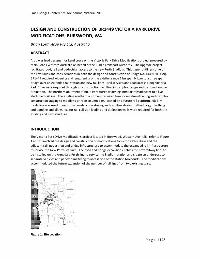
The Victoria Park Drive Modifications project located in Burswood, Western Australia, refer to Figure
1 and 2, involved the design and construction of modifications to Victoria Park Drive and the
adjacent rail, pedestrian and bridge infrastructure to accommodate the expanded rail infrastructure
to service the New Perth stadium. The road and bridge expansion enables the new railway lines to
be installed on the Armadale-Perth line to service the Stadium station and create an underpass to
separate vehicles and pedestrians trying to access one of the station forecourts. The modifications
accommodated the future expansion of the number of rail lines from two existing to six.
Figure 1: Site Location
Small Bridges Conference, Melbourne, Victoria, 2015
P a g e 2 | 25
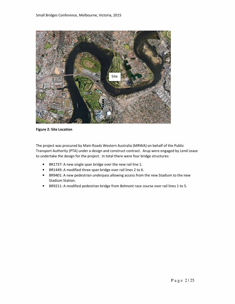
Figure 2: Site Location
The project was procured by Main Roads Western Australia (MRWA) on behalf of the Public
Transport Authority (PTA) under a design and construct contract. Arup were engaged by Lend Lease
to undertake the design for the project. In total there were four bridge structures:
• BR1737: A new single span bridge over the new rail line 1.
• BR1449: A modified three span bridge over rail lines 2 to 6.
• BR9401: A new pedestrian underpass allowing access from the new Stadium to the new
Stadium Station.
• BR9211: A modified pedestrian bridge from Belmont race course over rail lines 1 to 5.
Site
Small Bridges Conference, Melbourne, Victoria, 2015
P a g e 3 | 25
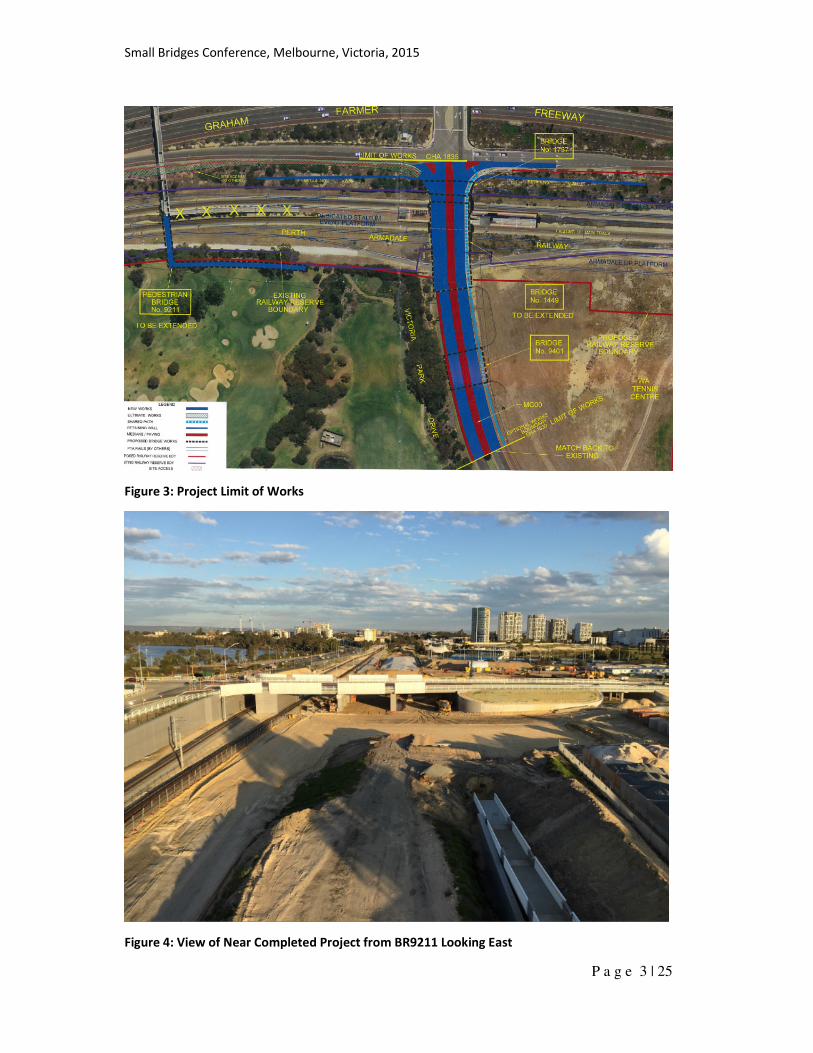
Figure 3: Project Limit of Works
Figure 4: View of Near Completed Project from BR9211 Looking East
Small Bridges Conference, Melbourne, Victoria, 2015
P a g e 4 | 25
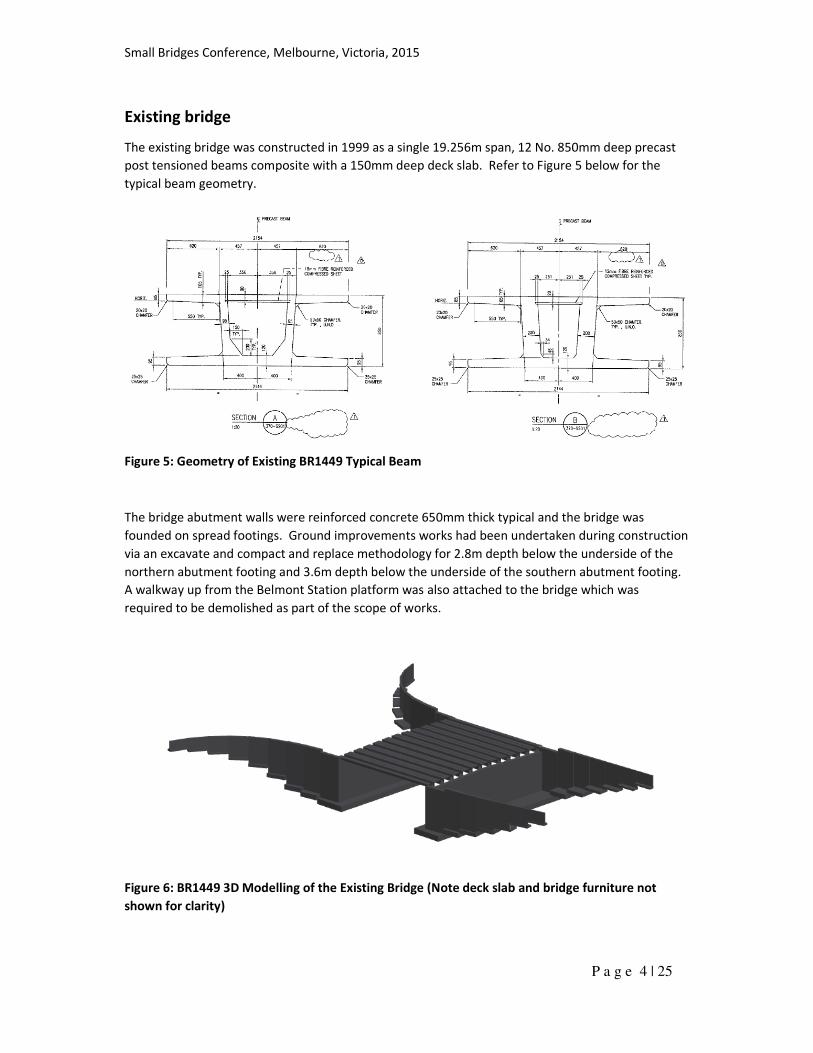
Existing bridge
The existing bridge was constructed in 1999 as a single 19.256m span, 12 No. 850mm deep precast
post tensioned beams composite with a 150mm deep deck slab. Refer to Figure 5 below for the
typical beam geometry.
Figure 5: Geometry of Existing BR1449 Typical Beam
The bridge abutment walls were reinforced concrete 650mm thick typical and the bridge was
founded on spread footings. Ground improvements works had been undertaken during construction
via an excavate and compact and replace methodology for 2.8m depth below the underside of the
northern abutment footing and 3.6m depth below the underside of the southern abutment footing.
A walkway up from the Belmont Station platform was also attached to the bridge which was
required to be demolished as part of the scope of works.
Figure 6: BR1449 3D Modelling of the Existing Bridge (Note deck slab and bridge furniture not
shown for clarity)
Small Bridges Conference, Melbourne, Victoria, 2015
P a g e 5 | 25
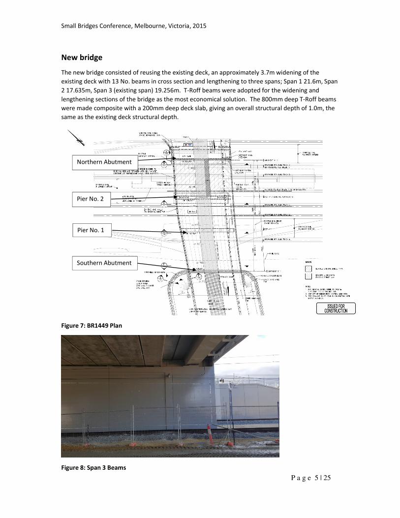
New bridge
The new bridge consisted of reusing the existing deck, an approximately 3.7m widening of the
existing deck with 13 No. beams in cross section and lengthening to three spans; Span 1 21.6m, Span
2 17.635m, Span 3 (existing span) 19.256m. T-Roff beams were adopted for the widening and
lengthening sections of the bridge as the most economical solution. The 800mm deep T-Roff beams
were made composite with a 200mm deep deck slab, giving an overall structural depth of 1.0m, the
same as the existing deck structural depth.
Figure 7: BR1449 Plan
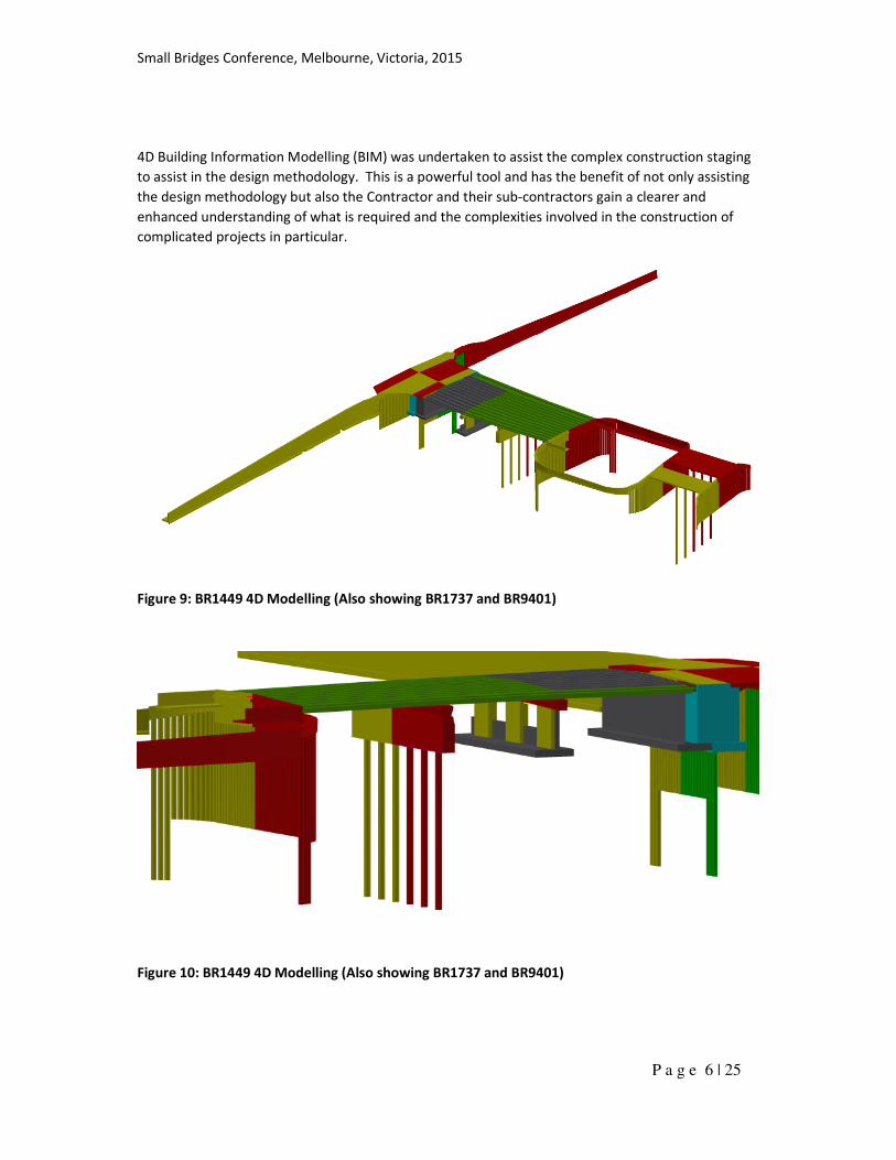
Figure 8: Span 3 Beams
Northern Abutment
Pier No. 2
Pier No. 1
Southern Abutment
Small Bridges Conference, Melbourne, Victoria, 2015
P a g e 6 | 25
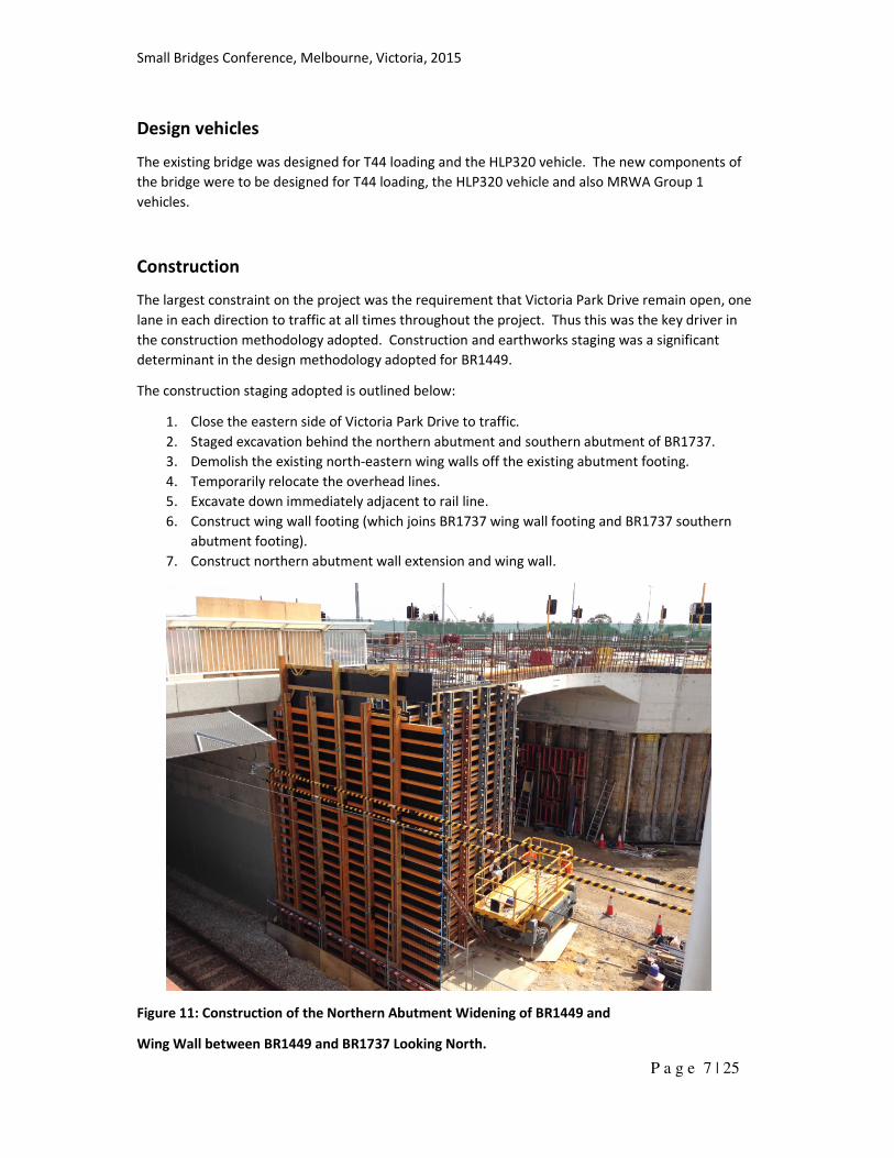
4D Building Information Modelling (BIM) was undertaken to assist the complex construction staging
to assist in the design methodology. This is a powerful tool and has the benefit of not only assisting
the design methodology but also the Contractor and their sub-contractors gain a clearer and
enhanced understanding of what is required and the complexities involved in the construction of
complicated projects in particular.
Figure 9: BR1449 4D Modelling (Also showing BR1737 and BR9401)
Figure 10: BR1449 4D Modelling (Also showing BR1737 and BR9401)
Small Bridges Conference, Melbourne, Victoria, 2015
P a g e 7 | 25
Design vehicles
The existing bridge was designed for T44 loading and the HLP320 vehicle. The new components of
the bridge were to be designed for T44 loading, the HLP320 vehicle and also MRWA Group 1
vehicles.
Construction
The largest constraint on the project was the requirement that Victoria Park Drive remain open, one
lane in each direction to traffic at all times throughout the project. Thus this was the key driver in
the construction methodology adopted. Construction and earthworks staging was a significant
determinant in the design methodology adopted for BR1449.
The construction staging adopted is outlined below:
1. Close the eastern side of Victoria Park Drive to traffic.
2. Staged excavation behind the northern abutment and southern abutment of BR1737.
3. Demolish the existing north-eastern wing walls off the existing abutment footing.
4. Temporarily relocate the overhead lines.
5. Excavate down immediately adjacent to rail line.
6. Construct wing wall footing (which joins BR1737 wing wall footing and BR1737 southern
abutment footing).
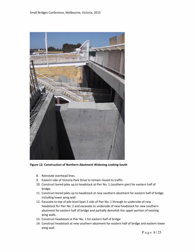
7. Construct northern abutment wall extension and wing wall.
Figure 11: Construction of the Northern Abutment Widening of BR1449 and
Wing Wall between BR1449 and BR1737 Looking North.
Small Bridges Conference, Melbourne, Victoria, 2015
P a g e 8 | 25
Figure 12: Construction of Northern Abutment Widening Looking South
8. Reinstate overhead lines.
9. Eastern side of Victoria Park Drive to remain closed to traffic.
10. Construct bored piles up to headstock at Pier No. 1 (southern pier) for eastern half of
bridge.
11. Construct bored piles up to headstock at new southern abutment for eastern half of bridge
including lower wing wall.
12. Excavate to top of pile level Span 2 side of Pier No. 1 through to underside of new
headstock for Pier No. 2 and excavate to underside of new headstock for new southern
abutment for eastern half of bridge and partially demolish the upper portion of existing
wing walls.
13. Construct headstock at Pier No. 1 for eastern half of bridge.
14. Construct headstock at new southern abutment for eastern half of bridge and eastern lower
wing wall.
Small Bridges Conference, Melbourne, Victoria, 2015
P a g e 9 | 25
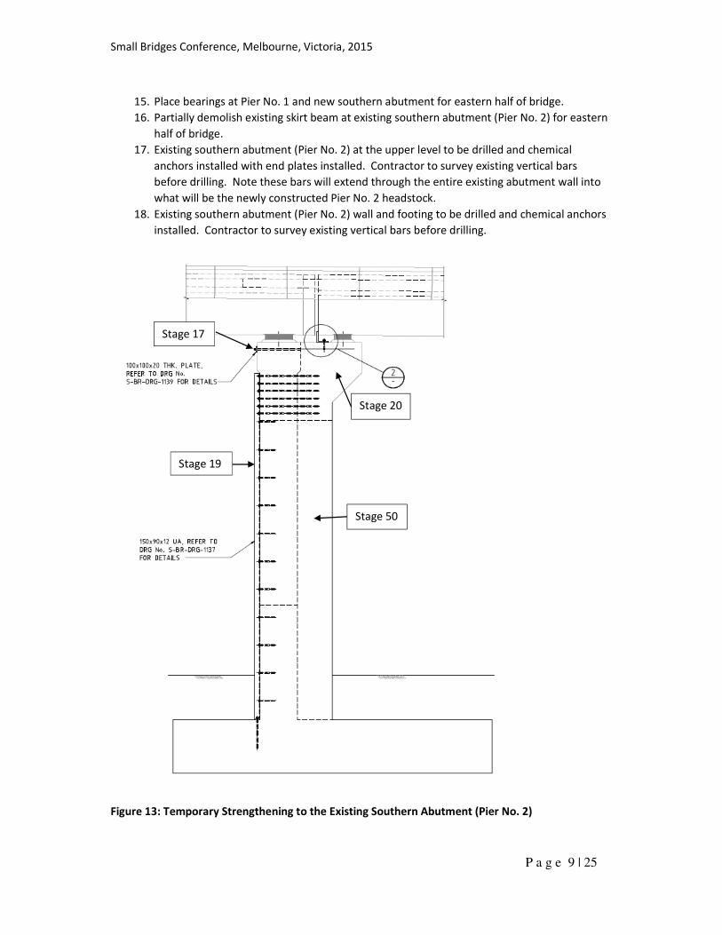
15. Place bearings at Pier No. 1 and new southern abutment for eastern half of bridge.
16. Partially demolish existing skirt beam at existing southern abutment (Pier No. 2) for eastern
half of bridge.
17. Existing southern abutment (Pier No. 2) at the upper level to be drilled and chemical
anchors installed with end plates installed. Contractor to survey existing vertical bars
before drilling. Note these bars will extend through the entire existing abutment wall into
what will be the newly constructed Pier No. 2 headstock.
18. Existing southern abutment (Pier No. 2) wall and footing to be drilled and chemical anchors
installed. Contractor to survey existing vertical bars before drilling.
Figure 13: Temporary Strengthening to the Existing Southern Abutment (Pier No. 2)
Stage 50
Stage 19
Stage 20
Stage 17
Small Bridges Conference, Melbourne, Victoria, 2015
P a g e 10 | 25
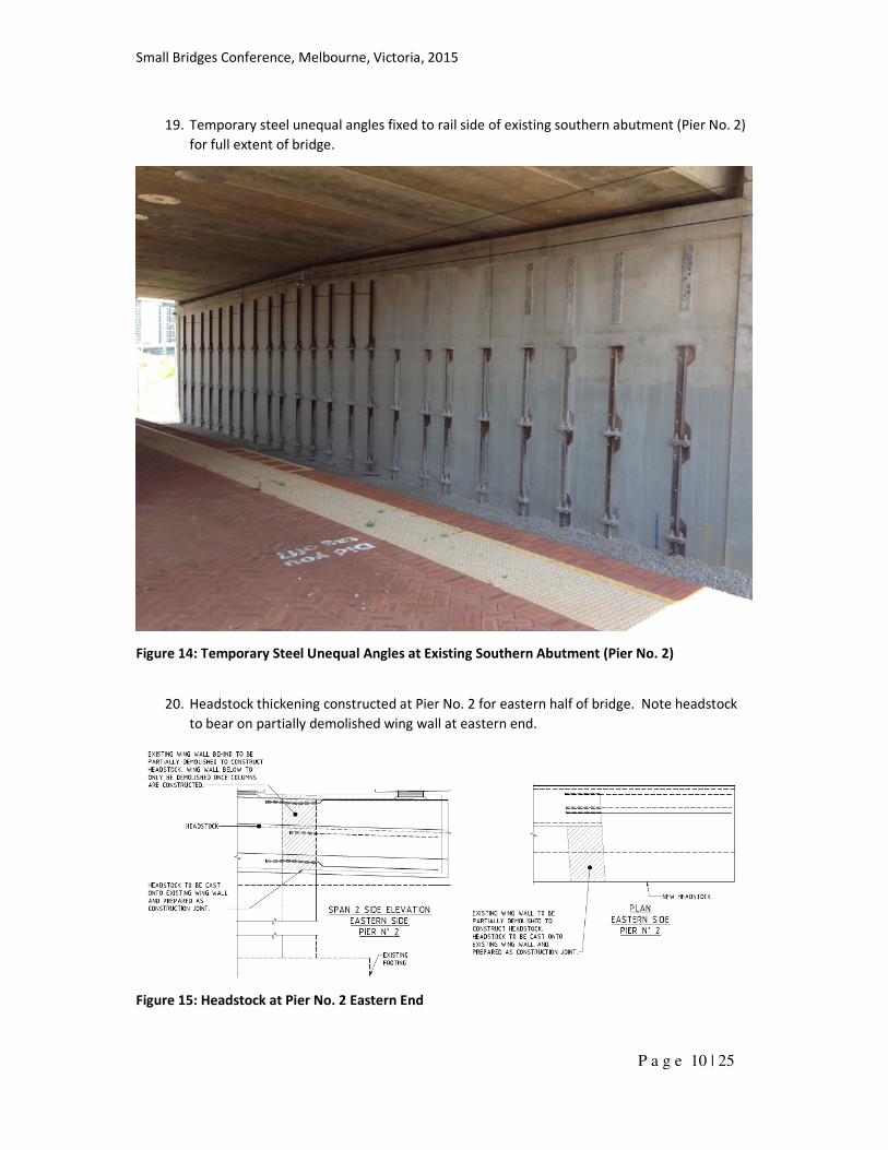
19. Temporary steel unequal angles fixed to rail side of existing southern abutment (Pier No. 2)
for full extent of bridge.
Figure 14: Temporary Steel Unequal Angles at Existing Southern Abutment (Pier No. 2)
20. Headstock thickening constructed at Pier No. 2 for eastern half of bridge. Note headstock
to bear on partially demolished wing wall at eastern end.
Figure 15: Headstock at Pier No. 2 Eastern End
Small Bridges Conference, Melbourne, Victoria, 2015
P a g e 11 | 25
21. Concrete to cure in accordance with project specification.
22. Place bearings at Pier No. 2 for eastern half of bridge.
23. T-Roff beams landed for Span 1, Span 2 and Span 3 for eastern half of bridge, after 14 days
and headstock concrete has reached its full design strength.
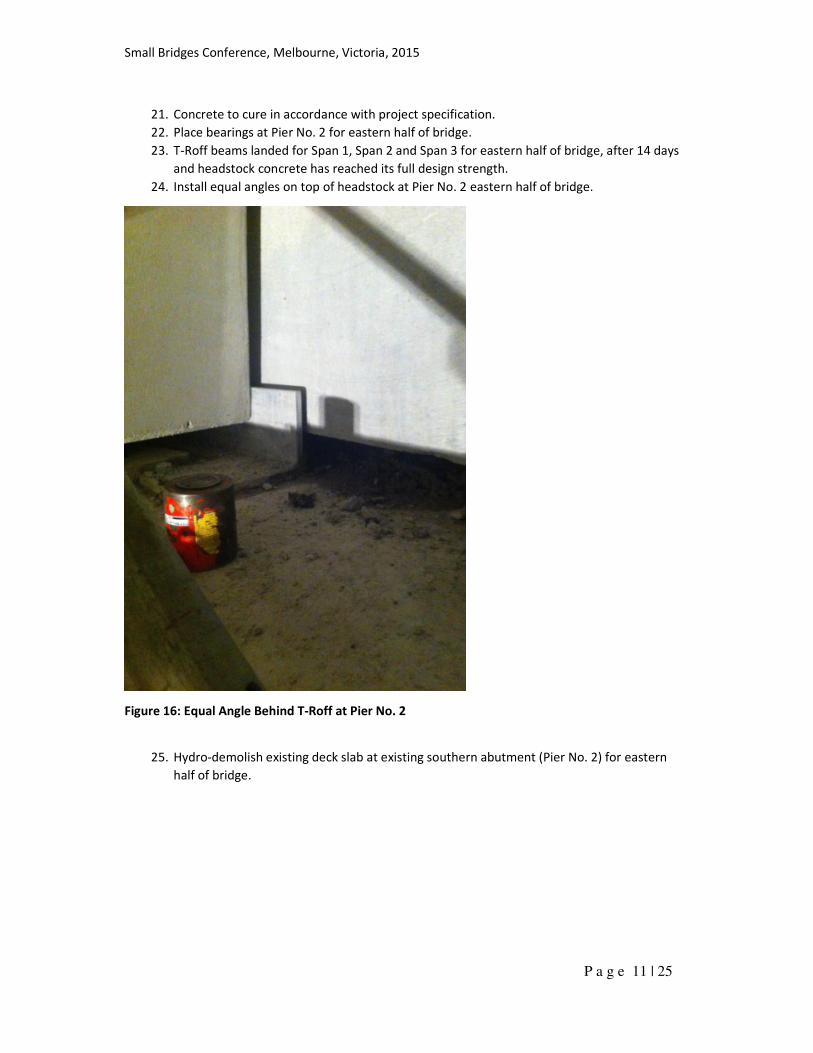
24. Install equal angles on top of headstock at Pier No. 2 eastern half of bridge.
Figure 16: Equal Angle Behind T-Roff at Pier No. 2
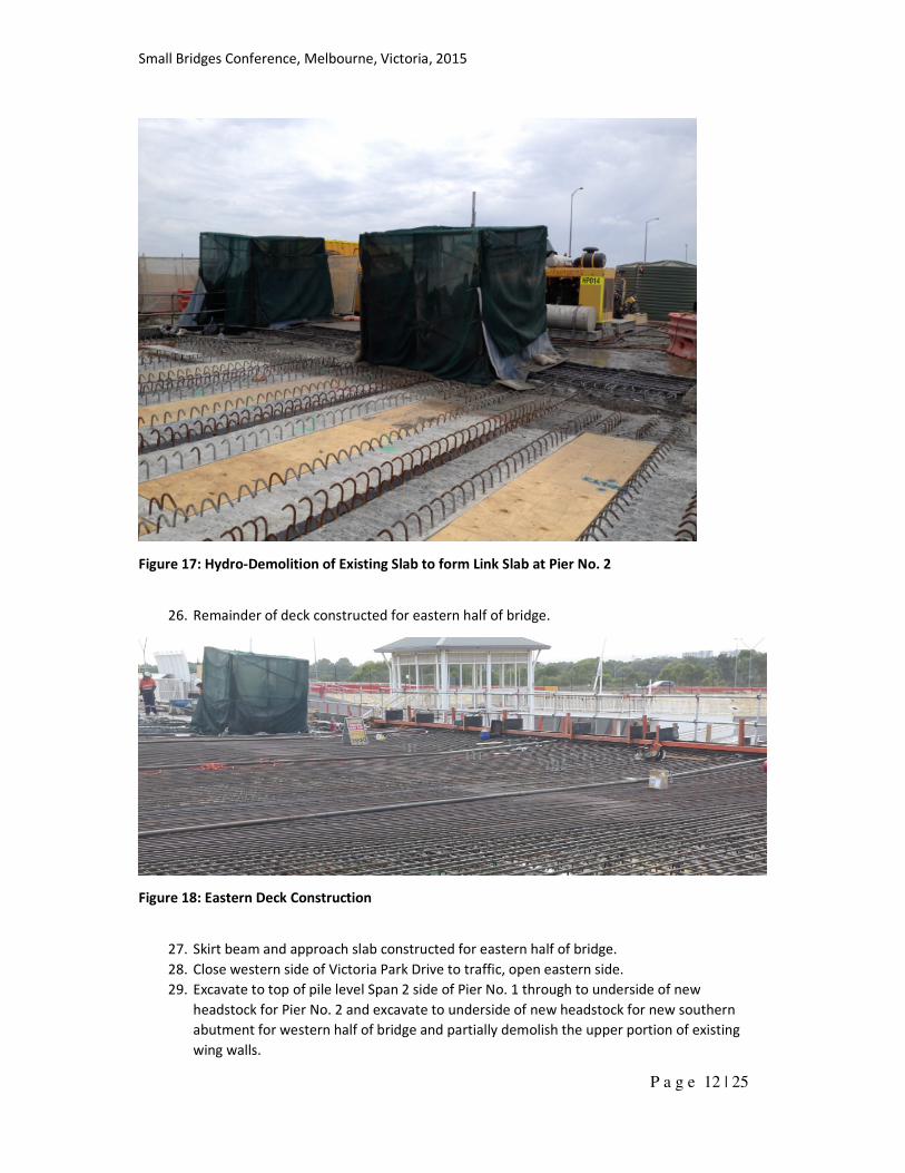
25. Hydro-demolish existing deck slab at existing southern abutment (Pier No. 2) for eastern
half of bridge.
Small Bridges Conference, Melbourne, Victoria, 2015
P a g e 12 | 25
Figure 17: Hydro-Demolition of Existing Slab to form Link Slab at Pier No. 2
26. Remainder of deck constructed for eastern half of bridge.
Figure 18: Eastern Deck Construction
27. Skirt beam and approach slab constructed for eastern half of bridge.
28. Close western side of Victoria Park Drive to traffic, open eastern side.
29. Excavate to top of pile level Span 2 side of Pier No. 1 through to underside of new
headstock for Pier No. 2 and excavate to underside of new headstock for new southern
abutment for western half of bridge and partially demolish the upper portion of existing
wing walls.
Small Bridges Conference, Melbourne, Victoria, 2015
P a g e 13 | 25
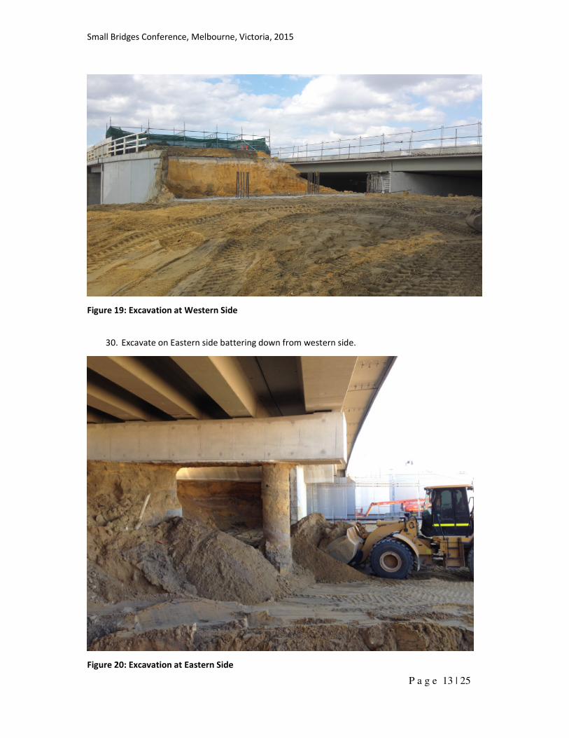
Figure 19: Excavation at Western Side
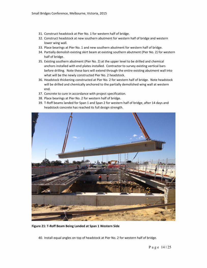
30. Excavate on Eastern side battering down from western side.
Figure 20: Excavation at Eastern Side
Small Bridges Conference, Melbourne, Victoria, 2015
P a g e 14 | 25
31. Construct headstock at Pier No. 1 for western half of bridge.
32. Construct headstock at new southern abutment for western half of bridge and western
lower wing wall.
33. Place bearings at Pier No. 1 and new southern abutment for western half of bridge.
34. Partially demolish existing skirt beam at existing southern abutment (Pier No. 2) for western
half of bridge.
35. Existing southern abutment (Pier No. 2) at the upper level to be drilled and chemical
anchors installed with end plates installed. Contractor to survey existing vertical bars
before drilling. Note these bars will extend through the entire existing abutment wall into
what will be the newly constructed Pier No. 2 headstock.
36. Headstock thickening constructed at Pier No. 2 for western half of bridge. Note headstock
will be drilled and chemically anchored to the partially demolished wing wall at western
end.
37. Concrete to cure in accordance with project specification.
38. Place bearings at Pier No. 2 for western half of bridge.
39. T-Roff beams landed for Span 1 and Span 2 for western half of bridge, after 14 days and
headstock concrete has reached its full design strength.
Figure 21: T-Roff Beam Being Landed at Span 1 Western Side
40. Install equal angles on top of headstock at Pier No. 2 for western half of bridge.
Small Bridges Conference, Melbourne, Victoria, 2015
P a g e 15 | 25
41. Hydro-demolish existing deck slab at existing southern abutment (Pier No. 2) for western
half of bridge.
42. Remainder of deck constructed for western half of bridge.
43. Skirt beam and approach slab constructed for western half of bridge.
44. Excavate to RL+2.6m underneath bridge for Span 1 and Span 2. Contractor to survey top of
southern abutment wall and bearings prior to excavation in front of the wall. Contractor to
monitor deflection of the top of the wall and bearings during excavation. If the deflection
reaches 30mm, the Contractor shall stop the excavation, notify the design engineer and re-
set the bearings individually one at a time.
45. Demolish remaining wing walls (note return wing walls on Pier No. 2 spread footing to
remain).
46. Locally excavate to RL+2.25m at Pier No. 1.
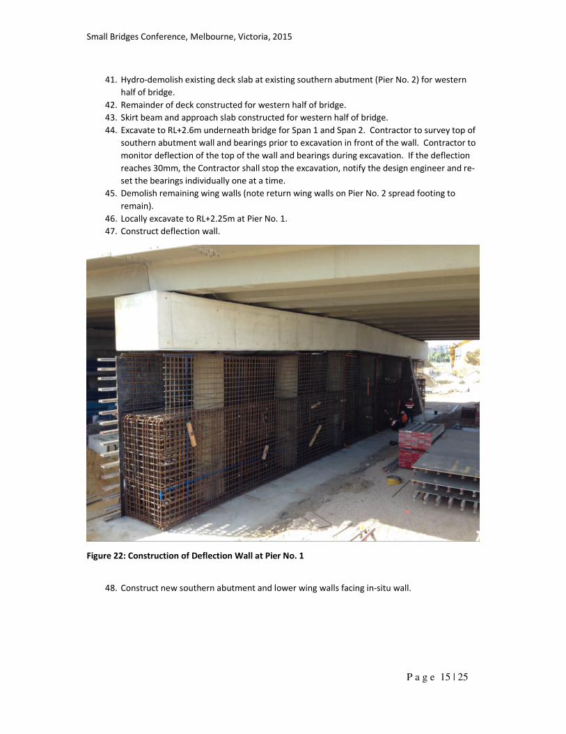
47. Construct deflection wall.
Figure 22: Construction of Deflection Wall at Pier No. 1
48. Construct new southern abutment and lower wing walls facing in-situ wall.
Small Bridges Conference, Melbourne, Victoria, 2015
P a g e 16 | 25
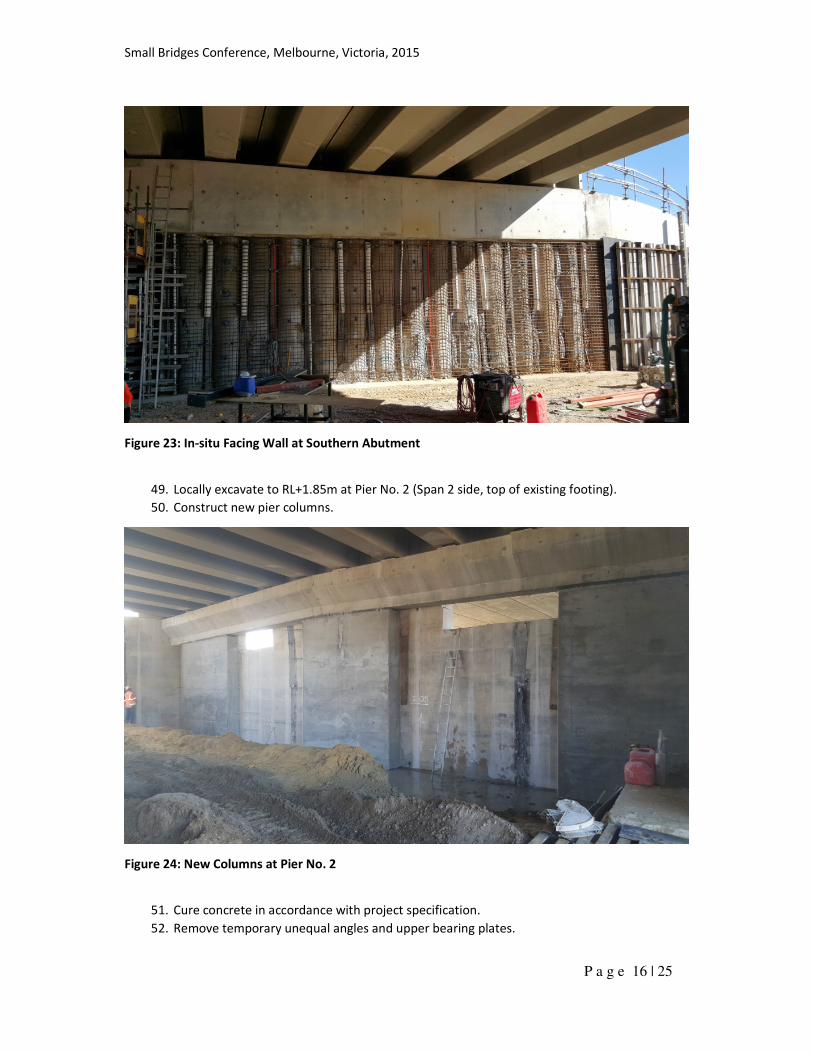
Figure 23: In-situ Facing Wall at Southern Abutment
49. Locally excavate to RL+1.85m at Pier No. 2 (Span 2 side, top of existing footing).
50. Construct new pier columns.
Figure 24: New Columns at Pier No. 2
51. Cure concrete in accordance with project specification.
52. Remove temporary unequal angles and upper bearing plates.
Small Bridges Conference, Melbourne, Victoria, 2015
P a g e 17 | 25
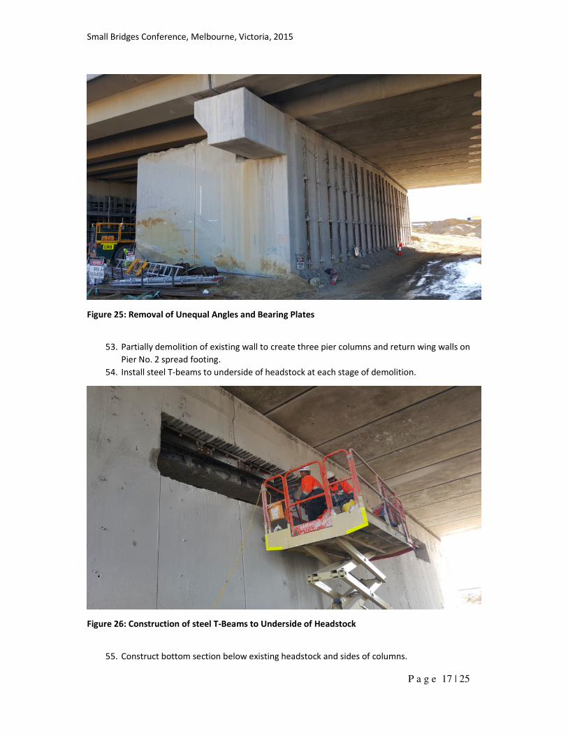
Figure 25: Removal of Unequal Angles and Bearing Plates
53. Partially demolition of existing wall to create three pier columns and return wing walls on
Pier No. 2 spread footing.
54. Install steel T-beams to underside of headstock at each stage of demolition.
Figure 26: Construction of steel T-Beams to Underside of Headstock
55. Construct bottom section below existing headstock and sides of columns.
Small Bridges Conference, Melbourne, Victoria, 2015
P a g e 18 | 25
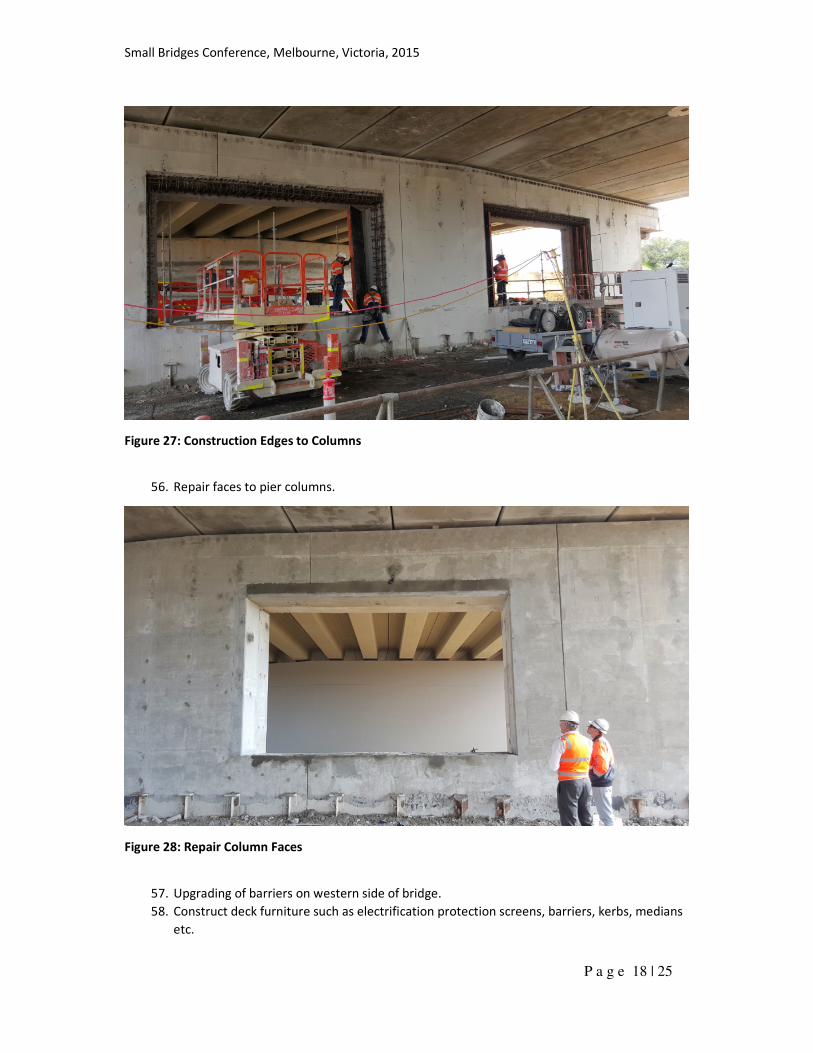
Figure 27: Construction Edges to Columns
56. Repair faces to pier columns.
Figure 28: Repair Column Faces
57. Upgrading of barriers on western side of bridge.
58. Construct deck furniture such as electrification protection screens, barriers, kerbs, medians
etc.
Small Bridges Conference, Melbourne, Victoria, 2015
P a g e 19 | 25
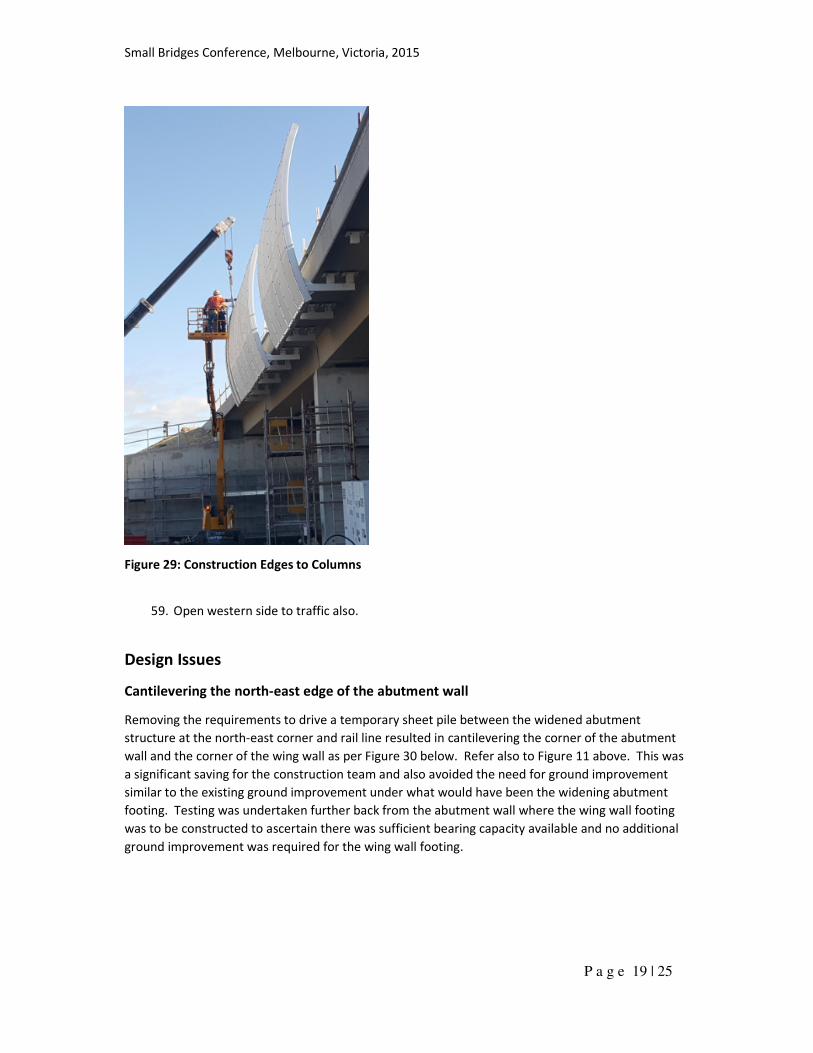
Figure 29: Construction Edges to Columns
59. Open western side to traffic also.
Design Issues
Cantilevering the north-east edge of the abutment wall
Removing the requirements to drive a temporary sheet pile between the widened abutment
structure at the north-east corner and rail line resulted in cantilevering the corner of the abutment
wall and the corner of the wing wall as per Figure 30 below. Refer also to Figure 11 above. This was
a significant saving for the construction team and also avoided the need for ground improvement
similar to the existing ground improvement under what would have been the widening abutment
footing. Testing was undertaken further back from the abutment wall where the wing wall footing
was to be constructed to ascertain there was sufficient bearing capacity available and no additional
ground improvement was required for the wing wall footing.
Small Bridges Conference, Melbourne, Victoria, 2015
P a g e 20 | 25
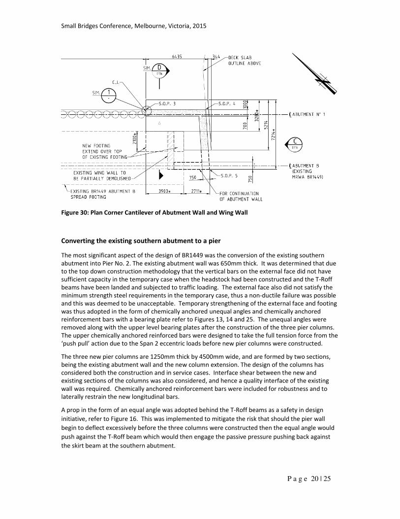
Figure 30: Plan Corner Cantilever of Abutment Wall and Wing Wall
Converting the existing southern abutment to a pier
The most significant aspect of the design of BR1449 was the conversion of the existing southern
abutment into Pier No. 2. The existing abutment wall was 650mm thick. It was determined that due
to the top down construction methodology that the vertical bars on the external face did not have
sufficient capacity in the temporary case when the headstock had been constructed and the T-Roff
beams have been landed and subjected to traffic loading. The external face also did not satisfy the
minimum strength steel requirements in the temporary case, thus a non-ductile failure was possible
and this was deemed to be unacceptable. Temporary strengthening of the external face and footing
was thus adopted in the form of chemically anchored unequal angles and chemically anchored
reinforcement bars with a bearing plate refer to Figures 13, 14 and 25. The unequal angles were
removed along with the upper level bearing plates after the construction of the three pier columns.
The upper chemically anchored reinforced bars were designed to take the full tension force from the
‘push pull’ action due to the Span 2 eccentric loads before new pier columns were constructed.
The three new pier columns are 1250mm thick by 4500mm wide, and are formed by two sections,
being the existing abutment wall and the new column extension. The design of the columns has
considered both the construction and in service cases. Interface shear between the new and
existing sections of the columns was also considered, and hence a quality interface of the existing
wall was required. Chemically anchored reinforcement bars were included for robustness and to
laterally restrain the new longitudinal bars.
A prop in the form of an equal angle was adopted behind the T-Roff beams as a safety in design
initiative, refer to Figure 16. This was implemented to mitigate the risk that should the pier wall
begin to deflect excessively before the three columns were constructed then the equal angle would
push against the T-Roff beam which would then engage the passive pressure pushing back against
the skirt beam at the southern abutment.
Small Bridges Conference, Melbourne, Victoria, 2015
P a g e 21 | 25
Chemically anchored reinforcement bars were also designed to transmit the full loads from the
existing top of wall section into new headstock section between columns. This was for robustness,
as the extended portion of the headstock was designed to take the full loads from Span 2 and 3.
When considering shear and torsion, the headstock section was designed as a rectangular section of
equal depth and approximately equivalent area and torsional modulus. Torsion was assumed
through the new section only as once the section cracks the existing section has minimal torsion
capacity, with no closed ligatures, or large corner bars. Torsion was designed considering steel
contribution only, and considering combined bending, shear and torsion. The wing walls on the
existing abutment footing were left in place until the columns were constructed as they allowed an
alternative load path, through torsion in the headstock beam back to the return walls.
Cast in steel T-beam sections were required in the temporary case and were also considered for
strength in the permanent case. The temporary section was designed for dead load only, whilst the
in service case section was designed for the full loading, considering the contribution of the
concrete/rebar cast around the section. The splice connection between T-beam sections was
designed to transmit the full tension load, and required TF bolts to ensure there was no slippage,
which would likely cause excessive cracking in the concrete. Interface shear capacity between
concrete sections was not considered as the new concrete was0 cast below the existing and hence a
good quality interface could not be ensured. Bolts were adopted to ensure longitudinal shear
capacity over the construction joint.
Upgrading the existing barriers
As part of the scope the existing barriers were required to be upgraded to regular performance
levels barriers. The original barriers had been previously designed for a lateral outwards collision
load of 90kN in accordance with ’92 Austroads Bridge Design Code. The regular performance level
barrier was required to be designed for a lateral outwards collision load of 250kN in accordance with
AS 5100. This was complicated by the existing deck slab only being 150mm deep. The existing
transverse reinforcement consisted of a layer of Y16-200 top and bottom. It was deemed the slab
only should be considered in the capacity as it could not be guaranteed that composite action would
be achieved with the top flange of the beam. The analyses determined that there was insufficient
capacity. The Contractor expressed a desire to minimise the extent of hydro-demolition thus a
design solution was determined to minimise the extent of hydro-demolition whilst providing a
solution which was relatively easy to construct on site.
The design solution relied on a strut and tie model where the design compression was taken via the
barrier into the L-shape plate and into the top flange of the beam. The design tension was taken via
the barrier into the reinforcement through welded connecting plates. The connecting plates were
welded on site at one end to the longitudinal 60mm thick main plate and at the other end to the
existing reinforcement. This solution thus provided the Contractor the flexibility of locating the
connecting plates relative to the existing reinforcement, whose location was not exactly known until
the deck slab had been hydro-demolished.
Rail collision loading/Deflection walls
A deflection wall was designed at Pier No. 1 refer to Figure 22. The deflection wall was constructed
from the ground up once the deck had been constructed above. AS5100 required the deflection wall
to be a minimum 3.6m above top of rail level. Thus initially there was a gap proposed between the

Small Bridges Conference, Melbourne, Victoria, 2015
P a g e 22 | 25
top of the deflection wall and the underside of the headstock. After consultation with the
independent project architect it was recommended that the gap between the deflection wall and
headstock be in filled with reinforced concrete for aesthetic purposes. Pier No. 2 was designed for a
collision load of 500kN as per AS 5100 as the SWTC allowed the future platform that would surround
the pier to be considered as a deflection wall.
The design methodology of the northern abutment was that the abutment was checked on either
side such that a 2m length of wall is removed for a height of 3.6m above top of rail level for a head
on collision and was found to be structurally adequate. Thus the first 2m length of wall for a height
3.6m above top of rail level was deemed to be acting as an integral deflection wall in accordance
with AS 5100. The northern abutment was also designed for a 1500kN normal collision load in
accordance with AS 5100 with passive resistance provided from the soil block behind the abutment
wall.
Earthing and bonding
Earthing is the practice of connecting exposed metallic components to the earth, such that currents
are diverted to the earth and dissipate. A correctly design earthing system will:
• Provide a safe return path for current in the event of an electrical fault and ensure that
sufficient current flows to cause the protective devices to trip out;
• Prevent conductors and components from reaching potentials higher than the rated
insulation voltage;
• Prevent a dangerous potential occurring between simultaneously accessible metallic
components;
• Prevent the generation of excessive voltages around the earthing system itself during fault
conditions;
• Provide a common reference potential that may be necessary for the correct functioning of
data processing or communications equipment.
Bonding is the practice of connecting exposed metallic components such that dangerous potential
differences do not occur between metallic components during a fault, even though these
components may be independently connected to the protective earthing system.
The overhead contact line zone and pantograph zone are zones in which structures and trackside
equipment could accidentally become live due to contact with broken overhead line equipment or
pantograph. If the contact wire were to snap and hit the above bridge soffit, the electrical current
would flow through to the bridge barriers and other metallic components, posing a high risk safety
hazard.
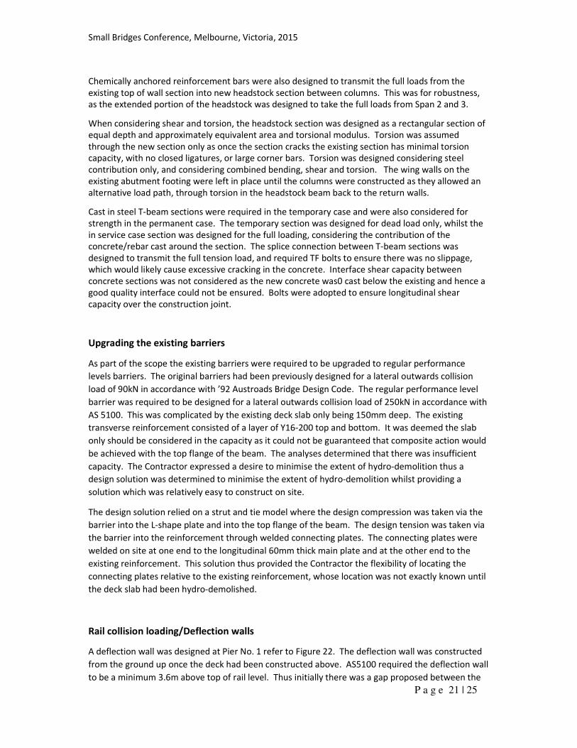
The zone in which such contact is considered probable is defined in Figure 31, where:
• HP is the highest point of the overhead contact line
• x = 4.0m (extended to 5.0m for tracks with curves less than 1000m)
• y = 2.0m
• SH = 8.0m above top of the rails
Small Bridges Conference, Melbourne, Victoria, 2015
P a g e 23 | 25
Figure 31: Overhead Contact Line and Pantograph Zone
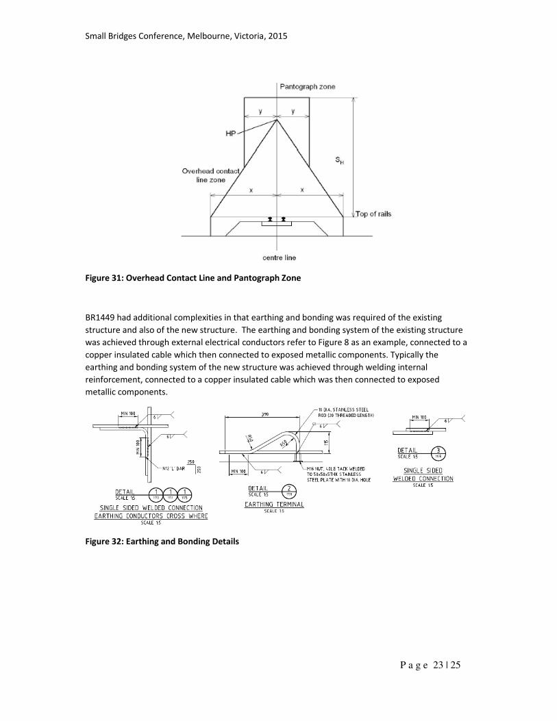
BR1449 had additional complexities in that earthing and bonding was required of the existing
structure and also of the new structure. The earthing and bonding system of the existing structure
was achieved through external electrical conductors refer to Figure 8 as an example, connected to a
copper insulated cable which then connected to exposed metallic components. Typically the
earthing and bonding system of the new structure was achieved through welding internal
reinforcement, connected to a copper insulated cable which was then connected to exposed
metallic components.
Figure 32: Earthing and Bonding Details
Small Bridges Conference, Melbourne, Victoria, 2015
P a g e 24 | 25
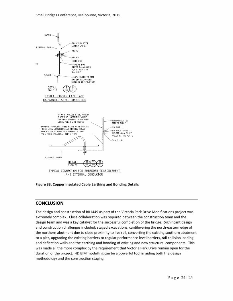
Figure 33: Copper Insulated Cable Earthing and Bonding Details
CONCLUSION
The design and construction of BR1449 as part of the Victoria Park Drive Modifications project was
extremely complex. Close collaboration was required between the construction team and the
design team and was a key catalyst for the successful completion of the bridge. Significant design
and construction challenges included; staged excavations, cantilevering the north-eastern edge of
the northern abutment due to close proximity to live rail, converting the existing southern abutment
to a pier, upgrading the existing barriers to regular performance level barriers, rail collision loading
and deflection walls and the earthing and bonding of existing and new structural components. This
was made all the more complex by the requirement that Victoria Park Drive remain open for the
duration of the project. 4D BIM modelling can be a powerful tool in aiding both the design
methodology and the construction staging.
Small Bridges Conference, Melbourne, Victoria, 2015
P a g e 25 | 25
REFERENCES
1. Standards Australia, (2004). Australian Standard AS 5100 – Bridge Design, Parts 1-7,
Standards Australia International Ltd, Australia.
2. Standards Australia, (1992). ‘92 Austroads Bridge Design Code, Parts 1-7, Standards Australia
International Ltd, Australia.
3. Scope of Works and Technical Criteria (SWTC), Contract 87/12, Victoria Park Drive
Modifications, Main Roads Western Australia.
4. Structures Engineering, Bridge Branch Design Information, Main Roads Western Australia.
5. Technical Instruction 228E – Guidelines for Earthing and Bonding in the 25kV AC Electrified
Areas”, Government of Western Australia, Public Transport Authority
ACKNOWLEDGEMENTS
• Arup; Julia Summers – Associate Principal; Kai Tan – Engineer; Peter Lees – Senior Drafter
• Lend Lease; Travis Tremain – Senior Project Engineer; Daniel Hamilton – Site Engineer
• MRWA; Steve Cole – Project Manager
• PTA; Kym Hockley
AUTHOR BIOGRPAHY
Brian Lord is a chartered Senior Civil Structural Engineer with an MBA in Arup’s Transport and
Resources team in Perth with approximately 11 years’ experience. During this time Brian has
worked on numerous road, rail and pedestrian bridges and a variety of maritime structures through
concept stage through to construction. Brian was the Structural Lead and then later the Project
Manager for the Victoria Park Drive Modifications project.


