
Volume 3, Issue 8, August – 2018 International Journal of Innovative Science and Research Technology
ISSN No:-2456-2165
IJISRT18AG69 www.ijisrt.com 60
Design and Construction of Bridge Embankment using
R.E. Wall Panels
S.Sandana Socrates1, Dr. S. Lavanya Prabha2, & S.Raja3
1PG Scholars, Department of Civil Engineering, Easwari Engineering College, India 2Professor& Head, Department of Civil Engineering, Easwari Engineering College, India
Abstract:- In this paper the analyses and design for the
bridge embankment have been made and the study of its
construction techniques is also explained. Excel and Plaxis
2D software are used for analysis of stabilities and
response of the structure. The bridge embankment consists
of skin, fill and soil reinforcement. The stability of
embankment depends on surcharge load, soil fill and soil
reinforcement. Para-web technology is a modern method
for soil reinforcement in embankment to replace Geo-grid.
Mechanically Stabilized Earth method is adopted for
construction of artificial embankment and Precast RE wall
panels are used as skin. Different types of filling materials
can be used of which fly ash is found to have higher
strength than other alternative materials. This paper can
help the future to construct artificial bridge embankment
in a simple and faster ways where less skilled labours are
required.
Keywords:- Embankment, Mechanically Stabilized Earth, Soil
reinforcement, Geo-grid.
I. INTRODUCTION
A. General
Bridge embankment is a combination of earth fill, linear
reinforcing strips and facing panels that are capable of bearing
highway load and large tensile stresses. In earlier method,
granular materials and soil were used as fill. The soil
reinforcements used in earlier method were steel bars and geo-
synthetic materials. The reinforcement provided by these
strips enable the soil mass to resist the tension in a way which
the soil alone could not resist. The source of this resistance to
tension is the internal friction of soil, because the stresses that
are created within the mass are transferred from soil to the reinforcement strips by friction.CIP Cantilever/ Counterfort
Retaining walls, Gravity Blocks Retaining wall and Sheet-
pile/Anchored walls were used as skin of the structure.
There is necessary for modernisation of bridge embankment using the results from the above construction
method. The factors considered for modernisation are faster
construction, pore water pressure, corrosion of soil
reinforcement, differential settlement, construction cost and
economical usage of land.
B. Objectives
To analyse and design the bridge embankment using the
design principle of reinforced earth structure.
To study on effective alternate components used for
embankment to replace the materials used in existing
method.
To study about the stability of embankment such as
External stability, Internal stability and Seismic stability.
To find out the forces and stresses produced in soil
reinforcement.
C. Advantages
Alternate construction materials (fly ash, polymeric strap
and pre-cast wall panels) used are light, easy to transport
and quick to construct.
The only machinery required is excavator and compactor.
Differential settlement is eliminated & bearing capacity is
increased.
Rapid construction is expected.
This technique can result in saving the area of land.
D. Important materials for embankment
1. Fly ash
2. Skin
3. Reinforcement
E. Fly ash
Soil or fly ash is the important component for
embankment to carry highway loads. It may be natural or
artificial material which depends on the location of
construction. It should be granular, cohesion less material and
for the case of silt or clay the particle size should not more
than 125 mm. The earth reinforcement coefficient of friction
to be either higher than or equal to 0.4 and Plasticity Index
should be less than 6. The soil must have moisture content
suitable for compaction. Fly ash (Class F) to be used as fills in
this method.
Fig 1:- Fly ash fill

Volume 3, Issue 8, August – 2018 International Journal of Innovative Science and Research Technology
ISSN No:-2456-2165
IJISRT18AG69 www.ijisrt.com 61
F. Facing elements (skin) Skin is the facing element of the reinforced soil wall.
This element keeps the reinforcement at a desired elevation in
the reinforced soil wall and also protects the granular material
at the edge of the soil mass from falling off. These are made of
either metal units or pre-cast concrete panels. It should be able
to deform without distortion.
Fig 2:- Precast RE wall panels
Fig 3:- Panel placement for initial course
G. Reinforcement for fill
A variety of materials can be used as reinforcing
materials such as Steel, Concrete, Glass fibre, Wood, Rubber
and Aluminium. Reinforcement may take the form of strips,
grids, anchors & sheet material, chains, planks, rope,
vegetation and combinations of these or other material forms.
The main aim of providing reinforcement in soil is to bear
large tensile stresses and to carry the facing elements from
falling off. For developing countries, polymeric strap is used
as soil reinforcement.
Fig 4:- Polymeric Strap as reinforcement
II. CONSTRUCTION METHODOLOGY
Fig 5:- Construction Procedure
Form and pour levelling pad
Set and brace the initial course of facing panels
Spread and compact backfill
Connect reinforcing strips to panel tie strips
Place bearing pads and set the second course of
full panels
Repeat cycle of backfilling and compacting in
lifts, connecting strips
Install traffic barriers
Excavation

Volume 3, Issue 8, August – 2018 International Journal of Innovative Science and Research Technology
ISSN No:-2456-2165
IJISRT18AG69 www.ijisrt.com 62
Existing method Modern method
Payments laid on natural
earth for transportation
purpose.
Embankment can be
raised artificially using
filler materials similar to
mechanically stabilised
earth.
Steel rods/meshes were
used as soil reinforcement.
Geo-grid/polymeric strap
can be used as soil
reinforcement.
Clay/silty soil or granular
materials were used as fill
for reinforced earth
structure.
Fly ash can be used as
filler material inside the
structure.
For facing of the structure,
gravity retaining
walls/cantilever retaining
walls were used.
Pre-cast wall panels can
be used as skin of the
structure and these are
interconnected to soil
reinforcement.
It needs large equipments
and construction area for filling and compaction
purposes.
It needs only simple
equipments for panel lifting, backfilling and
compaction processes.
Require high skilled
person.
Since it is a simple
technique, the structure can be completed with
less-skilled person.
Table 1. Comparison of methodology
A. Equipments
Panel lifting – A hydraulic crane, boom truck or similar
equipment is required.
Backfilling – Dump trucks, scrapers, dozers, graders, front-
end loaders, water trucks, etc, are used for hauling
dumping and spreading backfill. (Specific equipment
selection will depend on backfill, lift thickness,
compaction specifications, etc).
Compaction – Large smooth-drum vibratory rollers are
used for mass compaction of most backfills. Fine uniform
fills are compacted using a smooth-drum static roller.
Fig 6:- Sample c/s of Reinforced earth structure
III. STEPS INVOLVED IN DESIGN PROCESS
Load calculation
Design of reinforced earth structure
Fig 7:- Design steps
IV. ANALYSIS AND DESIGN
Design of reinforced earth structure consists of three
phases – 1.Stability, 2.Reinforcement strips & 3.RE wall.
A. Load
For 4-lane highway road (i) Class A & (ii) Class 70 R
are used (IRC: 6-2014 ‘STANDARD SPECIFICATIONS
AND CODE OF PRACTICE FOR ROAD BRIDGES’)
Table 2. Load comparison
Table 3. Partial Load Factors
B. Stability analysis
The stability analyses (External, Internal and Seismic)
are made using BS 8006: 1995- ‘CODE OF PRACTICE FOR
STRENGTHENED REINFORCED SOIL AND OTHER FILLS’.
DEAD LOAD 12 kN/m2
LIVE LOAD (
CLASS A )
23.23 kN/m2
LIVE LOAD (
CLASS 70 R)
20.46 kN/m2
Effects Load combination
A B C
Earth pressure behind
the structure
1.5 1.5 1.0
Traffic load behind
reinforced soil block
1.5 1.5 0.0
DESIGN STEPS
STABILITY REINFORCEMENT
STRIPS RE
WALL
Volume 3, Issue 8, August – 2018 International Journal of Innovative Science and Research Technology
ISSN No:-2456-2165
IJISRT18AG69 www.ijisrt.com 63
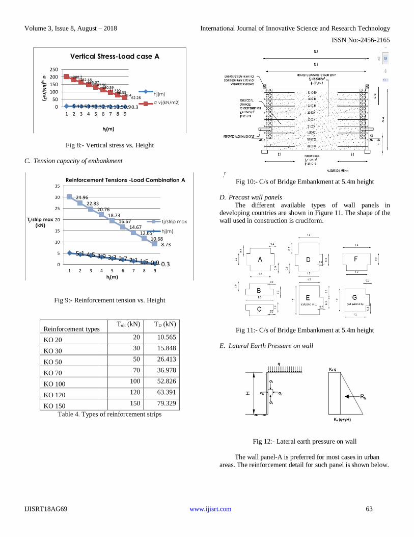
Fig 8:- Vertical stress vs. Height
C. Tension capacity of embankment
Fig 9:- Reinforcement tension vs. Height
Reinforcement types Tult (kN) TD (kN)
KO 20 20 10.565
KO 30 30 15.848
KO 50 50 26.413
KO 70 70 36.978
KO 100 100 52.826
KO 120 120 63.391
KO 150 150 79.329
Table 4. Types of reinforcement strips
Fig 10:- C/s of Bridge Embankment at 5.4m height
D. Precast wall panels
The different available types of wall panels in developing countries are shown in Figure 11. The shape of the
wall used in construction is cruciform.
Fig 11:- C/s of Bridge Embankment at 5.4m height
E. Lateral Earth Pressure on wall
Fig 12:- Lateral earth pressure on wall
The wall panel-A is preferred for most cases in urban
areas. The reinforcement detail for such panel is shown below.
5.14.53.93.32.72.11.50.90.3
200.2182.48
165.07147.96
130.59113.65
96.3379.4
62.28
0
50
100
150
200
250
1 2 3 4 5 6 7 8 9
σ v
j (kN
/m2)
hj(m)
Vertical Stress-Load case A
hj(m)
σ vj(kN/m2)
5.1 4.5 3.9 3.3 2.7 2.1 1.5 0.9 0.3
24.9622.83
20.7618.73
16.6714.67
12.6510.68
8.73
0
5
10
15
20
25
30
35
1 2 3 4 5 6 7 8 9
Tj/strip max
(kN)
hj(m)
Reinforcement Tensions -Load Combination A
Tj/strip max
hj(m)

Volume 3, Issue 8, August – 2018 International Journal of Innovative Science and Research Technology
ISSN No:-2456-2165
IJISRT18AG69 www.ijisrt.com 64
Fig 13:- Reinforcement details of RE wall
V. ANALYSIS USING PLAXIS 2D
Plaxis is a special purpose two-dimensional finite
element computer program used to perform deformation and
stability analyses for types of Geo-technical applications.
Typical PLAXIS applications include stability analysis of
embankments, displacements around an excavation pit, and
dam stability during different water levels. The applicability of
PLAXIS has been extended to solve problems dealing with
excavations in soft soils, piled-raft foundations, embankments
or dams with creep behaviour and its interaction with
consolidation and large deformation analysis. The challenges
that remain are the stability of embankments under conditions of drawdown, designing embankments on soft compressible
soils with low permeability of the underlying deposit together
with low undrained shear strength, dynamic movements of
embankments that determine the train speed, and migration of
finer materials during the long-term operation of an
embankment or a dam.
Fig 14:- Input data
Fig 15:- Total displacement of structure
Fig 16:- Distribution of axial forces on wall
Fig 17:- Shear force diagram
Fig 18:- Bending moment diagram

Volume 3, Issue 8, August – 2018 International Journal of Innovative Science and Research Technology
ISSN No:-2456-2165
IJISRT18AG69 www.ijisrt.com 65
Fig 19:- Total stresses
Fig 20:- Pore Pressures
VI. RESULTS & DISCUSSION
Analysis and design of embankment is done with the help
of Excel and Plaxis 2D.
The stabilities of structures are safe with safety factor
calculation.
The shape of Pre-cast wall panel used- cruciform.
The maximum tension capacity of reinforcement strips –
52.86kN.
The maximum stress produced in structure- 200kN/m2.
Plaxis 2D output- Extreme active pore pressure=60kN/m2, Extreme total principal stress= 91kN/m2, Total
displacement = 18x10-3mm.
VII. CONCLUSIONS
The most common application of reinforced earth is in
Mechanical Stabilized Earth Wall (MSEW) and Reinforced
soil slope (RSS).
Reinforced earth walls have evolved as viable technique
and contributed to infrastructure in terms of speed, ease of
construction, economy, aesthetics, etc.
It need little space in front of the structure for construction operations.
Do not need rigid, unyielding foundation support, because
reinforced or multi anchored structures are tolerant to
deformations.
A cast-in-place or precast unreinforced concrete levelling
pad serves as a smooth, level surface for placing panels.
The construction of reinforced earth structure has become
wide spread in Geotechnical engineering practice in the last two decades owing to their ease of construction and
economy compared to those of conventional methods.
Corrosion of steel reinforcing elements and deterioration of
reinforcement rods inside the fill will be unexpected to
occur due to the usage of polymeric strap.
The usage of Pre-cast wall panels aids in faster
construction and avoids the failure of wall in terms of
cracks and drainage.
Fly ash fill can overcome the deficiency of soil stability
with the influence of pore water pressure. It tends to give
higher compressive strength than soil.
The durability of Reinforced earth structure can be
expected up to more than 100 years than conventional
method.
VIII. ACKNOWLEDGEMENT
The author would like to thank the staffs Dr.S.Lavanya
Prabha and S.Raja for their continuous determination in
assisting the author to gather research materials for this paper
work and for those who had contributed to the cause of this
project. It is of great respect to all staffs who have also
contributed directly and indirectly to this paper and the whole research work.
REFERENCES
[1] Harangad Singh, Dr. Saleem Akhtar, Study of Cost
Economics of Retaining Wall over Reinforced Earth
Wall. International Journal of Emerging Technology and
Advanced Engineering Website: (ISSN 2250-2459, ISO
9001:2008 Certified Journal, Volume 5, Issue 11,
November 2015).
[2] Hj. Mohd Idrus, Overview and Preliminary Study of Approach - Slab Design Concept for Bridges, 2nd
International Conference on Rehabilitation and
Maintenance in Civil Engineering, Procedia Engineering
54 (2013) 774 – 784.
[3] D. Kishan, Analysis & design of 44 meter M.S.E.
(mechanically stabilized earth) wall by using plaxis 8.2.
International Journal of Advanced Engineering
Technology E-ISSN 0976- 3945, 2010.
[4] Edward J. Hoppe, Ph.D, Guidelines for the use, design
and construction of bridge approach slabs. P.E.Senior
Research Scientist, Charlottesville, Virginia, VTRC 00-R4, November 1999.
[5] Carmo Cardoso, Design and Analysis of Approach
Embankment Bridges over SoftSoils. Department of Civil
Engineering, Institute Superior Técnico, Universidade
Técnica de Lisboa, Portugal, 2006.
[6] Ioannis Zevgolis, Philippe Bourdeau, Mechanically
stabilized earth wall abutments for bridge support,
PublicationNo. FHWA/IN/JTRP-2006/38, SPR-285, April
2007.

Volume 3, Issue 8, August – 2018 International Journal of Innovative Science and Research Technology
ISSN No:-2456-2165
IJISRT18AG69 www.ijisrt.com 66
[7] Harangad Singh, A Review on Economic Analysis of
Reinforced Earth Wall with Different Types of Reinforcing Materials. Department of Civil Engineering,
UIT RGPV-Bhopal, Volume IV, Issue XII, IJLTEMAS
ISSN 2278 – 2540, December 2015.
[8] Construction and Quality Control Procedures Manual.
Corporate Headquarters, The Reinforced Earth Company
12001 Sunrise Valley Drive, Ste 400 Reston, VA 2019
(February 25, 2014).


