Download - DESIGN LUNAR SAMPLE CONTAINERS - NASA


i j
DESIGN STUDIES AND PROTOTYPE FABRICATION
OF
LUNAR SAMPLE CONTAINERS
December, 1965
for
NATIONAL AERONAUTICS AND SPACE ADMINISTRATION
Prepared under Contract NAS 9-4338
by
RALPH STONE AND COMPANY, INC.
ENGINEERS
Los Angeles, California

FOREWORD
The work reported herein was performed for the National Aeronautics and
Space Administration, Manned Spacecraft Center, Houston, Texas, under Con-
tract NAS 9-4338. The contract authorized a six-month study commencing
May 22, 1965, for continuing work in lunar geologic and biologic sample
acquisition, packaging and return. The study was conducted under the cog-
nizance of the Lunar Sample Receiving Laboratory with Donald A. Flory serving
as the NASA Technical Representative.
Acknowledgement is extended to members of the Early Apollo Sciences Teams
who contributed time and advice, including Drs. Clifford Frondel, James R.
Arnold, P. R. Bell, A..J. Tousimis, and Klaus Bieman.
All work on the contract was performed under the overall cognizance of
Ralph Stone, President. Directly assisting the contractor's staff on the
details of the study were Drs. Gregory Jann, (bacteriology), John C. Simons, Jr.,
@acuum technology), and Lewis D. Felton, (structures and dynamics). Members
of the contractor's staff assigned to the work were E. T. Conrad, D. A. Link,
and H. J. Steinberg. 3. A. Borges, Jr., M. S. Israel, H. F. Newman, and
A. W. Dickinson, Jr., Senior Staff Engineers, were also assigned to perform
specialized phases of the study. E. A. Webster directed the program and
served as Project Manager.
Corporation, Chula Vista, California,
RALPH STONE AND COMPANY, INC.
ENGINEERS

TABLE OF CONTENTS
FOREWORD
CONTENTS
LIST OF FIGURES
SUMMARY
INTRODUCTION
RECOMMENDATIONS
PART I - PROGRAM OBJECTIVES
PART II - SAMPLE BOX DESIGN STUDIES _
Size and Shape
Guides and Self-Centerlng Pins
Cover
Pin Retraction and Handle Mechanisms
Thermal Control
Instrumentation
Receiving Station Interface Considerations
PART III - STRUCTURAL DESIGN STUDIES
Basic Material Selection
Structural System Design Selection
Mounting Systems
Page
li
ill
v
I
3
5
12
12
15
\
16
17
19
21
22
28
28
31
32
iii

TABLEOF CONTENTS (Cont.)
PART IV - SEAL SELECTION
Candidate Seals
Final Selection (Indlum-Solder Seal)
PART V- - PACKAGING STUDIES AND
SPECIAL PURPOSE INNER CONTAINERS
l
Canister Concept
Flexible Bags
Gas Sampling Container
Protobiological Sampling Container
Storage Provisions
PART VI - PROTOTYPE HARDWARE FABRICATION
Wall Configuration
Framing Configuration
Joining Techniques
Penetrations
Handle and Pin Retraction Mechanisms
Internal Canisters
Seal Hardware
APPENDIX A
APPENDIX B
APPENDIX C
APPENDIX D
- Structural Calculations
- Comments from the Scientific Community
- Test Results and Special Analyses
- Bibliography
iv
Page
38
38
42
48
48
50
53
57
60
61
61
62
62
63
63
63
64
65
89
98
109

LIST OFFIGURES
l,
2.
3.
4.
Cover Latches
Initial Mockup
Mockupof Straight-Pull Handle and Pin Retraction System
Final Mockup
5. Weight Indication Alternatives
6. Outbound (translunar) Seal Configuration
7. Proposed Sterilization Manifold
8. G-Loading Diagram A
9, G-Loadlng Diagram B
I0. Single-Mass System Model
ii. Spring Force Diagram
12. Crush Gasket Design
13. Indium-Solder Seal Design
14, Packaging System Evolution
15. Preferred Sample Stowage Arrangements
16, Proposed Flexible Bag Dispenser
17, G_s Sampling Inner Container
18.
19.
20.
21.
22.
23,
24.
Protobiological Sampler
Aseptic Sample Container
Cold Weld Seal Test Coupons
Seal Test Equipment
Seal Test Fixture
Indium Test Fixture
Vacuum Test Data
Page
16 _
18
18
20
23
25
26
'33'
34
35
36
40
43
49
51
54, 55
56
58
59
99
102
102
102
105

DESIGN STUDIES AND PROTOTYPE FABRICATION
OF
LUNAR SAMPLE CONTAINERS
RALPH STONE AND COMPANY, INC.
ENGINEERS
SUMMARY
The prior study contract, reported in NASA document CR65000, established
basic objectives and constraints for the sample return container program.
Particular emphasis was placed during the study phase on scientific mission
requirements, working within applicable mission-oriented definitions of phy-
sical and climatic environments supplied by NASA, including astronaut limi-
tations and spacecraft interfaces.
The current work emphasized design optimization of the sample box.
Detailed evaluations were completed on such phases as structural and fabri-
cation techniques, cover and latching systems, handle configurations and
seal designs, as well as a review and design study of the sample protection
system, inner containers and a bag dispensing system.
The study also encompassed fabrication of four mockups of the sample
return box and internal canister arrangement, showing progressive design
improvements as the program matured. In addition, two prototype boxes were
fabricated to permit tess and evaluations by NASA of the various design
concepts finalized during the current phase of work.
The sample box designs now call for a stainless steel honeycomb paral-
lelepiped, approximately 7 1/4 by Ii by 18 3/4 in., having a full-opening
ii x 18 3/4 in. lid. Access to the vacuum-sealed box on the lunar surface •
will be accomplished by pulling a cable through the ductile nickel membrane
seal. The return or transearth seal is a unique indium-solder design per-
mitting zero leakage and requiring little effort on the part of the astronaut.
The outside of the box is coated with white zlncIoxide for passive ther-
mal control, while the inside is selectively fluorocarbon-coated to prevent
metal to metal contact. The inside of the box is filled with open-topped
canisters approximately 2 1/2 in. square which can be removed as required to
accommodate any desired sample configuration. With the canisters in place,
optimum protection is provided for individual samplesf
- i -
t
Rock samples will first be packaged in flexible laminated metal foil
bags, which are packed into the canisters by the astronaut. A bag dispensing
device is proposed for opening, closing, and sealing without intermediate
handling by the astronaut. The device consists e§sentlally of a clean bag
storage cylinder, guide rails and seal crush-rollers mounted with a pistol
grip configuration. Being battery-operated all functions except filllng
occur automatically on a single trigger squeeze_
The proposed inner container intended for gas sampling is a polished
stainless steel cylinder utilizing an indium crush gasket. ' Access for the
analyzer sensing probe is through a port sealed by a foil rupture diaphragm.
The proposed protobiological sampling device is a double-barreled pointed
probe designed to obtain samples from 6 to 18 in. beneath the lunar surface.
Sample material is acquired in a specially designed telescoping cartridge which
is capped and returned to a storage container without exposure to astronaut-
or surface-orlginatedcontaminants.
Throughout the design and fabrication phases coordination was maintained
with leading members of the Early Apollo Sciences Teams, as well as experts
at NASA-MSC and various manufacturers of special materials and equipment.
-2-
ip

INTRODUCTION
The samplereturn programencompassesvarious packaging techniques andequipmentrequired to preserve lunar surface material until ready for pro-cessing in the Lunar SampleReceiving Laboratory. Guidelines for a protec-tion systemwere evolved in mid 1964, whenpackaging of geologic samples inflexible bags, preservation of special purpose specimensin small, rigidinner containers, and storage of all sample-containing units within a rigid,drawer-like samplebox aboard the LEM_ere proposed.
The first study contract on lunar sampling and samplereturn methodswas completed in March 1965. The study described morespecifically certaindesign recommendationsfor maintaining minimumcontainer weight, controllingcontamination sources, optimizing sampleprotection, andminimizing demandson the astronaut throughout the acquisition and packaging activities. Thecurrent contract extendedthe prior activities to include detailed engineer-ing and prototype fabrication of certain specific items of container hard-ware. Details of the work performedunder the presenti phaseof the contractare presented in six technical sections, the contents of which are as follows:
PARTI: PROGRAMOBJECTIVES.- This section describes the scope of thecurrent programand includes a tabulation of specific design criteria andconstraints applicable to the samplebox and inner container hardware.
PARTII: SAMPLEBOXDESIGNSTUDIES.- Overall design features of thesamplebox are summarized,including size and shape, cover and fastener
design, mountingprovisions, pin retraction and handle mechanisms,temperature,pressure andweight instrumentation, and receiving station interface conside-rations.
PARTIII: STRUCTURALDESIGNSTUDIES.- A synopsis is presented of thedesign approachfor materials selection, wall and framing structural design,and weight optimization. Dynamicand static considerations are also revie-wedwith respect to box mountingprovisions.
PARTIV: SEALSELECTION.- Various candidate seals are analyzed, rang-ing from elastomers and crush gaskets to the indium-solder concept. A com-parison is presented betweenthe seal concepts and the mission design goals,together with a description of problemareas to be evaluated during prototypetests.
PARTV: PACKAGINGSTUDIESANDSPECIALPURPOSEINNERCONTAINERS.- Thebasic packaging and special container studies are reviewed, including thecanister concept for sampleprotection, the flexible inner bags for packaging
L
-3 -

rock • samples, metal cylinders proposed for samples to be used for gas analysis,
and the protobiological sampling system. The section also summarizes the
problems of maintaining sufficient packaging flexibility to accommodate a
wide range of possible sample types, and methods are proposed for minimizing
dependence upon the astronaut's limited time and dexterity for dispensing
sample bags and obtaining aseptic subsurface samples.
PART VI: PROTOTYPE HARDWARE FABRICATION. - Fabrication methods and
techniques for the two prototype boxes are discussed including details On
wall and framing configurations, joining technique s , and seal hardware.
Appendices include structural calculations, a summa£y of the comments
of the scientific community relative to box and packaging requirements, test
results and a bibliography. A Drawing Supplement is provided • under separate
cover containing reduced scale reproductions of pertinent •prototype hardware
designs, as well as a List of Materials.
- 4 "

RECOMMENDATIONS
Test Program
Comprehensive test procedures should be defined to evaluate the proto-
type hardware fabricated during the current work. The intent of the initial
series of tests should be to determine the suitabRity of the•proposed hard-
ware in terms of mission requirements. Subsequent review and coordination
with the scientific community are recommended to verify design judgment in
areas •of specific experimental interest.
While not a formal qualification series, the evaluations should be
designed to uncover physical deficiencies quickly and efficiently by con-
centrating on those areas of traditional weakness or greatest susceptibility
to failure. A summary of the recommended test program follows.
Seal_ return. - The seal test program should define the criteria and
test instrumentation for evaluating leakage throughout the functional en-
vironments expected during the mission.
Specifically, the studies to be completed in a 10 -5 torr or lower vacuum
environment should include susceptibility of the seal to contamination and
the effectiveness of the protective fluorocarbon shields, the melting tempe-
rature, the time required for heating and cooling the indium, the heater
wattage required, the effectiveness of the indicator light to determine the
indium melting point, the suitable time lag established before shutting off
the power source. Since penetrations are not provided on the as-delivered
prototypes, suitable instrumentationmust be specified and adapted to the
test unit. The possibility of using radioactive gas as a means of leak
detection should also be evaluated.
Seal_ outbound. - Similar instrumentation and techniques devised for
the return seal study program should be adapted to test the leakage charac-
teristics during the outbound mission profile. In addition, further tests
are needed to determine the susceptibility of the cover to cold welding
during long storage periods, the ease of removal of the outbound tear-away
seal under high vacuum, and the probability of seal rupture and failure due
to accidental rough handling.
Structural tests. - Uniform 14. 7 psi atmospheric loading will provide
3/4 of design load for static structural evaluations. Structural design
verification tests include determinations of wall and cover deflections in
a hyper-baric chamber at 20 psi differential pressure.
- 5 -

Dynamic tests should be performed if possible with the boxes mounted
in the same frame configuration as will be used in the LEM and Command
Module. Tests to specification dynamic environments should be performed on
the empty and loaded box in both the outbound and inbound seal configurations.
Such evaluations should include individual samples_packaged in flexible bags
to study wear and abrasion characteristics.
LEM interface. - Tests in thermal vacuum equipment at the time the LEM
prototype is evaluated would be useful in determining ease of installation
and handling characteristics on the loaded and unloaded box.
Human factors. - An evaluation of the outbound box configuration should
be accomplished to study the effectiveness of the tear-away seal and the
outbound cover spacer. In addition, the handle and pin retraction system
should be tested by space suit technicians, together with coverhandllng
and latching characteristics.
Additional Designs and Fabrication
Wei_ht-optlmized prototype. - Current calculations indicate up to eight
pounds of additional samples can be returned by utilizing advanced concepts
evolved as a result of this study. Final designs and selection of materials
for such a welght-optimized prototype should be commenced immediately.
Design improvements, if any, evolved during structural tests of the current
prototypes should be included on this unit for study prior to releasing
proof hardware for fabrication.
Manufacturing specifications. - Following design verlfication tests on
the current and weight-optimizedprototypes, manufacturing specifications
delineating materials, dimensions, assembly and cleaning techniques should
be prepared for the fabrication of proof hardware.
Protoblological sample container and dispenser. - Designs_ould be com-
pleted for a protobiological sampling system to obtain asceptic samples, from
..................... w _== _ULL_ surface. Mockups would be helpful in
obtaining early design evaluation and appKoval by MSC and advisers in the
Early Apollo Sciences Teams. Prototype hardware should be fabricated illu-
strating design characteristics and permitting full evaluation of the physi-
cal and -aseptic characteristics of the sampling dispenser and containers.
Gas samplin8 container. - Current recommendations for the container to
be used for gas analysis should be analyzed and mockups prepared for MSC
evaluation. Prototypes should be fabricated at an early date to permit
detailed evaluations by scientific advisers.
-6 -
i"
I

Drive tube. - A simple device for obtaining surface samples, consisting
of a cartridge-like cylinder driven by foot into the lunar surface, should
be studied and design recommendations evolved for consideration by MSC.
Packaging tools. - Current design analyses should be completed and a
mockup of a packaging tool for use with flexible bags prepared. The device
should be designed to minimize the astronaut's activity by semi-automatically
(I) dispensing open sample bags, (2) positioning the bags for easy filling,
and (3) sealing after filling.
Flexible bags. - Flexible bags compatible with the packaging tool
equipment should be designed and prototypes fabricated in i, 3, and 7 in.
diameter sizes.
- 7 "
f
!i

i •
I
PART I
PROGRAM OBJECTIVES
INTRODUCTION
The purpose of the Lunar Sample Container Program is to integrate the
needs of the scientific community with Apollo mission objectives and con-
straints to produce optimum designs for the return of lunar samples.
In general, the consensus of scientific requirements centered on the
return of the maximum possible payload, packaged in such a manner as to
minimize physical damage and contamination. Fabrication of the boxes from
materials of known and suitable chemical composition was considered essen-
tial to ensure accurate differentiation between samples and packaging trace
contamination during post-mission analysis and study programs.
Mission-oriented design requirements included: (I) configuration, weight,
and mounting interface constraints; (2) pre-launch, Command Module, LEM, and
lunar climatic environments; (3) functional environments such as vibration
and shock; (4) astronaut mobility, dexterity and time limitations; and (5)
pre- and post-mission _ isolation and sterilization precautions.
Work under this phase of the program followed the completion of basic
feasibility studies and was broadened to include special purpose container
designs, studies of problems in seal and structural optimization, and manu-
facturing techniques, tentatively identified in the initial investigations,
PRIOR WORK
The initial study contract produced the basic criteria for sample con-
tainer design, including the outer container, flexible inner bags for geologic
samples, and special purpose inner containers intended for scientific experi-
ments such as gas analysis and biological investigations.
The study also analyzed the practical impact of the extremely low con-
tamination levels demanded by scientific constraints and the extent of these
limitations on the choice of container materials and as-manufactured cleanli-
ness. The problems of protecting against contamination of the sample and
packaging systems due to external sources such as descent engine effluent,
astronaut outgassing and the transearth environments of the LEM and Command
Module were reviewed. The results of that study were published in April, 1965,
under the title "Investigations of Lunar Sampling and Sample Return Methods_'_
NASA Document CR65000.
" 8 --
i

.P
CURRENT WORK
To minimize confusion in the report due to terminology, the technical
presentation will refer to the large outer sample return containers as
"boxes," the inner packaging modules described in Part V as "canisters,"
the flexible containers as "bags," and the special purpose gas and proto-
biological sample containers as "inner containers."
Work Performed
The principal objectives of the current study were to optimize seal
and structural designs for the overall sample return system and to fabricate
two prototypes of the large, vacuum-sealed sample boxes. Concurrent with
this work was further study to define designs for (I) weight, temperature,
and pressure monitors, (2) bag dispensing techniques, (3) a gas sampling
inner container, and (4) a protobiological sample inner container.
Additionally, overall design support was provided in the area of manu-
facturing technology, as well as interface coordination with scientific
experimenters and Early Apollo Sciences Team members.
Design Goals
Guidelines for the design and selection of prototype hardware were
derived from applicable NASA specifications and scientific requirements.
The objectives, grouped and tabulated according to major study areas, are
defined in Table I.
- 9 -L

TABLE I
Item Design Objectives
1. MaxlmumUnloaded Container Weight
2. Maximum Loaded Container Weight
11.5 pounds, as defined in GrummanICD LTS-360-22102.
50 pounds, per above reference.
3. Maximum Container Size As definedby LEM, CIM interface
drawings, Grumman LID 360-22802,
NAAMH01-12001-116.
4. Apollo Engineering MaterialsConstraints
Materials to be compatible with
Grumman ICD LIS-360-22101 or approved
exception.
5. Structural Integrity Samples to be retained but vacuum may
fall under 78 g impact. Hold vacuumunder randomvibration.
6. Sample Packaging Materials To be compatible in all respects with
scientific requ_ements, as well as
Grumman ICD LIS-360-22101 or approved
exceptions.
. Miscellaneous Environmental
Specification Compliance
8' Environmental Compatibility
Per NASA General Working Paper
No. 10,030, "Environmental Specifi-
cations for Apollo Scientific
Equipment," dated August iI_ 1964.
All parts and materials to retain
their essential functions and proper-ties in the lunar environment_
9. Thermal Range -64°F to +i87_.
i0. Passive Thermal Control
II. Lunar Vacuum
12. Passive Vacuum Retention
150°F maximum.
I0 -I0 tort.
10 -5 tort.
13. Seal Redundancy Secondary seal to prevent grosscontamination and retain vacuum
integrity to 10-2 tort.
- I0 -

15.
TABLE I -
Pre-Misslon Vacuum Preparatlon
Pre- and Post-Mission
Sterilization
16. Crew Requirements
17. Packaging Flexibility
18. Sample Damage Protection
i9. Lunar Materlals Effects
20. Contamination
Concluded
Desi_q Objectives
Following solvent wash and normal
vacuum vessel cleaning, box internal
materials to be baked 96 hours,250oF under 10-9 tort vacuum to
minimize further outgasslng. Follow
with electron brushing.
Materials and configurations to be
compatible with methods of steril-
ization selected for post-misslon
handling. In general, pre- and
post-mission high temperature baketo be limited to 250oF.
Handles,latches, seal caps, packag-
ing, and stowage equipment to be
readily operable by gloved astronauts
as designated by MSC Crew Systems
personnel.
Design to be fully adaptable size,
configuration and degree of protection
to range of materials likely to befound on lunar surface.
To be designed for 78 g impact, plus
random vibration per Apollo mission
requirements.
Seals, mating and sliding surfaces
to be protected from or insensitiveto lunar dust or debris.
Box and packaging of lunar samples
to provide control of contamination
from foreign compounds or organisms,
whether oflunar or non-lunar origin.
- ii-

PART II
.I
SAMPLE BOX DESIGN STUDIES
INTRODUCTION
The configuration and maximum size of the envelope in which the sample
boxes are transported within the spacecraft were defined to the Contractor
by Command Module and LEM interface drawings, together with the general
method of attachment and the location of the box-to-structure mounting points.
The objective of the configuration study was to place an optimum payload
within these envelope constraints consistent with the scientific and mission
objectives described in Part I.
Descriptions of overall design features only are included in Part II.
Specialized structural implications 0f various alternate configurations
are described in Part III, "Structural Design," while the development of
final designs for the vacuum seal are described in Part IV, "Seal Selection."
The design of special purpose inner containers and the management of internal
box space for sample protection are included in Part V, "Packaging Studies
and Special Purpose Inner Containers."
SIZE AND SHAPE
Table II summarizes clearances, overall dimensions, and volume utili-
zation. It will be noted that additional clearance allowances over the
minimum specified on the interface drawings have been provided. One reason
for this is to permit shock mounts to be evaluated on the prototypes, if
comprehensive dynamic testing proves them to be needed. Full utilization
of the allowable envelope for box structure would have precluded this degree
the volume may be added to the proof hardware boxes without jeopardizing the
usefulness of present test hardware.
The second reason for retaining the extra clearance was to allow more
flexibility in the choice of certain peripheral hardware such as electrical
or instrumentation connectors, the vacuum probe penetration, outbound welded
- 12 -

TABLE II
DIMENSIONAL SUMMARY
NO.
l.
2.
3.
Item
Width
Height
Depth
Box Dimension Requirements, InchesA B C D
Ship's Current ShockStructure Permissible Box Mount
(C/M) Box Envelope Dimensions Clearances
19.160 19.00 18.91 0.250 (I)
8.160 8.00 7.41 0.750 (2)
11.600 11.50 11.45 0.150 (3)
(I) Clearance divided equally on both sides, 0.125 per side.
(2) Height clearance divided 0.250 above, 0.500 below box.
(3) Depth clearance divided 0.130 to the rear of the box,
0.020 front clearance behind flush edge of structure.
External and Internal
Volumes, Cubic Inches
Weight-
Optimized
Weight- Prototype
Current Optimized with Min.
Prototype Prototype Clearance
. (E) Total volume, ship's
storage compartment,(dimensions from
column A, above) ........ 1814 1814 1814
. External volume of
maximum permissible
box (dimensions from
column B, above) ........ 1748 1748 1748
6. (G) External volume of
box as designed ........ 1604 1604 1748 (4)
7. (H) Gross internal volume
of box as fabricated ... 1299 1349 1482
8. (i) Useful internal volume
of canisters ........... 1243 1293 1426
(4) Assuming shock mounts not required.
- 13 -

TABLE II - Concluded
DIMENSIONAL SUMMARY
No. Item
9.
10.
11.
12.
13.
Volume Utilization,Cubic Inches
Specification clear-ances, (E-F_
Additional clearances
for possible futureshock mount deflections
and external hardware,
(F-G)
Volume of box walls,
Handle and latch
protrusions
Volume lost in canisterwalls and clearances
Useful volume
TOTAL VOLUME, in. 3
Current
Prototype
66
144
275
30
56
1243
1814
Weight-
OptimizedPrototype
66
144
225
30
56
1293
1814
Weight-
Optimized
Prototypewith Min.
Clearance
66
236 ,
30
56
1426
1814
- 14 -

m
exterior seals, tethers, or other protrusions. In addition, the 0.5 in.
bottom clearance provides a potentially useful storage space for a collaps-
ible sunshade, weighing stand, or other hardware currentlY under consideration
but not yet defined. The inclusion of these parts within the box would in
part defeat cleanliness objectives by requiring the outbound seal to be
broken early in the mission and might necessitate a revision in the internal
sample protection canister scheme to make room for non-modular items.
GUIDES AND SELF-CENTERING PINS
Fluorocarbon guide rails 0.420 in. high are provided to bring the mounting
pins to within normal self-centering distance of the holes. Should it be
desired to use flexible shock isolation in place of the current mounts, other
suitable guide members will be provided. Alternatively , if the space is not
required for deflection clearance or hardware storage, the final box dimension
will be enlarged and thin (0.010 in.) fluorocarbon strip runners will replacethe 0.420 in. rails.
Centering rails are not required for the 0.125 in.•side clearances,
since the end taper on the mounting pins is sufficient to accommodate the
maximum sideways positioning dimension.
COVER
Configuration
Recommendations from the previous study for a circular or oval-shaped '
lid were based on anticipated difficulties in providing a reliable seal,
particularly if high unit loading crush-gaskets were to be used. The indium-
solder seal concept described in Part IV made it possible to reconsider the
cover design, resulting in a full-opening plate concept. The seal design,
being self-centering and relatively uncritical dimensionally, eliminated the
requirement for a hinge or articulated cover swing mechanism. During the
first mockup design review, preference was shown by NASA-MSC for an unhinged
lid, possibly using a tether between cover and body.
Redundant Fasteners
Nearly 700 Ib force is exerted on the top of the box lid by the gas
pressure in the Command Module.
However, in the event the two heater elements fail to melt the indium, '
redundant latches (see Fig. i) are provided to hold the lid in place and to
- 15 -

FIGUREi
INDANT SEAL
SPRING LATCHDETAIL
INDIUM (MELTED)
LATCH SHOWN IN INBOUND
(TRANSEARTH) POSITION
MECHANICAL SPRING LATCH
( PREFERRED METHOD)
[] Ii
___,\ J
_LOCAL HEATING- ,
,__-1 °__'"Tu_"-_-'1.,
PARALLEL ._7 py-I_)_T'EcHN/c _)WIRES PILLOW HEATERS
DETAIL_
PYROTECHNIC HEATERSPOT WELDS
(ALTERNATE METHOD)
RALPH STONE _ CQ, INC.ENGINEERS
DECEMBER 1965
REDUNDANT COVERSECURING CONCEPTS
- 16 -

allow the secondary elastomeri¢ seal to function while the box is returned
to the LEM and later transferred to the Command Module.
The redundant fasteners also provide additional structural protection
to the indium seal, preventing the edges of the lld from rotating due to
static loads. By preventing edge rotation, lid deflection is also minimized.
An alternate system which was considered but later rejected for struct-
ural reasons consisted of a series of pyrotechnic "pillows." These units
were intended to spot-weld the indium at six locations around the seal peri-
meter in the event the heaters failed to function (see Fig. I). The pillows
would be fabricated of welded stainless steel hollow wafers, approximately
0.2 in. by 0.2 in. to retain all products of the exothermal reaction. The
pyrotechnics would be activated simultaneously by closing the initiating
circuit with a panel-mounted switch connected to a small, separate battery
stored in the limited-use space beneath the handle well in the front of the
box.
Box Level Indication
To seal the cover to the box, the indium in the seal gland must be heated
to slightly above its melting point and allowed to freeze. To make certain
that the indium height remains reasonably constant over the length of the
seal gland, it will be necessary to level the box. This can be done by pla-
cing one of the astronaut's hand tools, equipped with a level, on the flat
provided for that purpose in the center of the cover and adjusting the con-
tainer orientation as required.
PINRETRACTION AND HANDLE MECHANISMS
Preliminary Designs
The principal constraints on handle designs were that it be (i) stowed
mmu_. w_L. L.= _u_mau= um L.= box a,Lu _m) r_a_y _=u_zD_ and =orre=
sized for the heavily glove astronaut. The first designs submitted for
mockup review utilized soft fabric for the handle and separate latches on
either side of the box to retract the front mounting pins (see Fig. 2).
While the strap was of minimal weight and volume, its flexibility detracted
from the astronaut's ability to manipulate and steer the box. The latches,
while efficient and easy to actuate, required two large wells for finger
access and made it necessary for the astronaut _shift his hand from one
side to the other when removing or storing the box.
- 17 -

FIGURE 2
INITIAL MOCK-UP
FIGURE 3
RALPH STONE a co., INC. MOCK-UP OF STRAIGHT-PULL ENGINEERS HANDLE AND PIN RETRACTION
DECEMBER 1965 SYSTEM
- 18 -

The second unit (see Fig. 3) submitted for evaluation was a straight-
pull handle which retracted the two front mounting pins when extended from
the "stowed" to the "carry" position. While being an improvement of the
two-latch concept in terms of volume use and astronaut handling, locking
characteristics were considered deficient.
Final Design
The combination 90 ° rotation handle and pin retraction assembly shown
in Fig. 4 was efficient from a volume and weight standpoint, had positive
latching characteristics, provided more positive feel for carrying and steer-
ing, and had better handle access than either of the previous designs.
To ensure positive latching, each of the tandle positions is fully
detented, requiring the handle _ be depressed against a positivespring
load before rotating from the "latch' to the "carry" position. In the
"carry' position the weight of the box aids the spring load in ho!ding
the handle in detent, preventing inadvertent rotation while maneuvering.
Construction and manufacturing details of the latch assembly are presented
in the Drawing Supplement.
THERMAL CONTROL
The optimum thermal control is a passive coating which would be used
to maintain the box at an equilibrium temperature of 120-150OF when exposed
tosunlight. However, even with reflectivlty factors of .9 and higher, the
box temperature is expected to exceed 150°F over a period of several hours.
Additional polishing to improve the thermal balance was considered, but the
resultant glare would make the box difficult to use while handling and pack-
aging samples. In addition, the thermal coating efficiency may be expected
to degrade noticeably due to deposition of layers of lunar dust, making itseffectiveness doubtful.
An alternate solution which could be used in addition to Coating is to
provide a collapsible or inflatable sunshade. Either concept might be
combined with a stand containing a weighing device.
- 19 -

FIGURE 4
INTERIOR VIEW SHOWING CENTER CANISTERS REMOVED
HANDLE IN STORED POSITION CARRYING POSITION ( MOUNTING PINS RETRACTED)
RALPH STONE 8 CO.,INC. ENGINEERS
DECEMBER 1965 FINAL MOCK -UP
- 20 -

INSTRUMENTATION
Seal Melt Indicator
A simple means of determining when the indium-solder seal has melted
(reference Part IV, "Seal Designs") is to use the melted indium to complete
an electrical circuit. The schematic of this system consists of a 250 milli-
ampere light on the front handle well, wired in series to a suitable battery
and with two open junctions five inches apart in the indium seal well The
ends of the open Junction wires_are inserted in small cavities within the
indium and protected from shorting by insulated spacers, until submerged by
the melted indium. No other switch or circuit component is required, the
light remaining on until the battery burns out.
Temperature Indicator
The primary design objective for temperature indication was to provide
a readout instrument on the surface of the box to show the average temperature
of the payload space. Various mechanical schemes such as bi-metallic elements
proved impractical because of lack of sensitivity and because they were diff-
icult to position in areas indicating sample payload temperature, rather than
that of the conducting walls near the element. Various self-contained thermo-
couple devices were evaluated but were rejected primarily because the readout
indicators were too large and heavy. In addition, the sophistication of the
equipment greatly exceeded the requirement for an average, gross indication
of the equilibrium temperature of the payload.
Several alternate solutions were considered. One, thermal indicating
paint, could h_ applied at various points to the outside of the boxes to
indicate gross maximum temperature at such locations. A second alternative
was to install several permanent thermocouple junctions within the payload
space, connected through a penetration to a plug in the front of the box.
Meaningful data could then be ob£alned by the use of recording instruments,
either during the missioncr upon return to earth. Finally, sample temper-
ature could be determined on the lunar surface by the astronau_ with a port-
able sensor, indexing samples to specific bag numbers by voice recording.
Pressure Indicator
At the present time there is no requirement to instrument the boxes
for hard vacuum pressure indication. However, it would be useful to have
a means of determining if gas pressure were increasing, whether from seal
- 21 -
failure or sublimation of samples. A most promising design for gross pressureindication employsa metallic bellows which flexes with pressure changesandextends a direct-connected red-tipped probe 1/8 in. from the face of the re-cessedhandle well. In the event the internal pressure should exceedby i psithe external pressure on the box, a pointed extension on the bellows wouldrupture a thin metal diaphragm.
Weight Measurement
Themaximumweight permitted in either box by LEMand CommandModuleinterface specifications is 50 ib, while the maximumfor both boxes togetheris 70 lb. Thus, a simple go, no-go weight indicator is insufficient, anda reasonably accurate (_ 2%)scale must be provided.
Building the weight indicator into the box handle is feasible froma design standpoint, andwould require very little addedweight. However,becausethe sampleswould have to be secured from falling out as suggestedby the alternative shownin Fig. 5, other techniques are being explored. Forinstance, a separate NASAcontract to develop hand tools includes investigat-ing meansof weighing individual samples. The samedevice might be adaptableto weighing the entire samplecontainer in its loading orientation by use ofthe sling concept illustrated in Fig. 5.
RECEIVINGSTATIONINTERFACECONSIDERATIONS
Final Pre-mission Cleaning and Outgassing
An intermediate sized vacuumchamberfive to six feet in diameter shouldbe equippedwith an infrared array designed to apply even, controlled heat •to the inner surfaces of the box, the seal cavity, and the individual canis-ters. The handling assemblyshould be designed so that the aluminumcanisterscan be bakedat approximately 450°F, while the box itself should be maintainedbelow 200°F so as not to induce permanentchangesin the shapeof variousfluorouarbon bearing assemblies. It is recommendedthat, if possible, pres-sures lower than I x 10-9 torr be maintained during this period. Whengasload sensing instrumentation has indicated that sufficient pumpinghas beendone to have cleaned the surfaces (estimated to be ten to fourteen days), thecanisters should be placed within the box and the lid positioned for weldingof the outboundseal without removingany of the parts from the vacuum.
- 22 -

FIGURE 5
PICK OR OTHER HAND TOOL
IN FLIGHT
STORAGES
POSITION OF
SLING
BETWEEN
WEIGHINGS
I
WEIGHING SLING
USING HAND-HELD SCALE
i
SHROUD SHOWN_ f---BETWEEN WEIGHINGS-_IN WEIGHING _ t L. ........... __T..\\POSITION _ ........... _'_'_ I
°il -I <
HANDLE SCALE
RALPH STONE 8_ CO. INC.ENGINEERS
DECEMBER 196,5
ALTERNATE
WEIGHING CONCEPTS
- 23 -

Outbound Seal Installation
As described in Part IV, the indlum-solder seal will be used only for
the return flight. The outbound seal will be a thin strip of metal between
the body and lid which will be sheared on the moon with the aid of a thin
cable and ring (see Fig. 6). The metallic shear strip must be electron-
beam welded in a special holding fixture in the aforementioned vacuum cham-
ber. Since this procedure will produce the final closure of the container,
the degree of vacuum and Cleanliness achieved will largely be determined by
the quality of the vacuum equipment and chamber in which the seal welding
is accomplished. The protective elastomeric cover assembly used to prevent
sharp edges from being exposed can be installed at any time prior to launch.
Sterilization
Many'concepts for solving the complicated sterilization problems have
been investigated. One step toward pre-sterilizing the interior of the
assembly will have been accomplished in the hard vacuum bake-out procedure
described in the paragraph on pre-mission cleaning. Following the handling
and check-out of the box after welding, final pre-mission sterilization will
be accomplished with a combination of procedures to be determined by NASA.
To aid in reaching internal cavities in the pin retract mechanism and mount-
ing holes, a system of small diameter tubes manifolded to a single fitting
in the front of the box is recommended to permit liquid or gaseous disinfec-
tants to be utilized. Following the use of such procedures, boil-off of
residual disinfectants should be accomplished under protracted mild heat
and vacuum (8 hours, 150°F, 10 -6 torr). Similar problems exist in handling
the boxes at the completion of the mission, except that biological contami-
nation will be minimized by the use of remote manipulators. The complete
sterilization process, including connection to the suggested manifold fitting,
must be accomplished by remote means. (Reference Fig. 7)
Gas Sampling
A gas sampling port will, when defined by NASA, be provided in the
front of the box. A pointed probe will be inserted into the port to rupture
a thin metal diaphragm prior to opening the box lid at the receiving station
laboratory.
Unsealing
The indium-solder seal simplifies the problem of lid removal, since the
same electrical connection used for sealing on the lunar surface can be uti-
lized to reheat the indium. Should this circuit fail, a secondary heater
- _' -

OUTBOUND
COVER SPACER
( PROTECTIVEFLUOROCARBON
FILM NOT SHOWN)
CABLE
i
RALPH STONE 8 CO.,INC.ENGINEERS "
DECEMBER 1965
FIGURE 6
WELDEDBODY
NICKEL STRIP
TO COVER AND
"_ PULL TAB
OUTBOUND (TRANSLUNAR)SEAL CONFIGURATION
- 2.5 -

'i
r
I
_----- ,,II
II
], ltl/ ,,- _lli J_> .tJ
__q,
i!II
"IL
,/
<7>
• _E
,_1
W
m
o
W
z_
°zl,.,o_-z
oo
u.
.>.
F- 00
N
.J
O"hlF-O_
Z
O
z_o_
n-
- 26 -

can be readily applied in the form of a band around the outside of the lid.
Should both means fail, the shear strength of the indium is sufficiently
low that a force of 15 Ib per lineal inch will remove the lid. If the
redundant hook-detent fasteners are used as recommended, a means of cutting
or prying these from the box perimeter must be provided. In all cases,
either the lid should be removed within a vacuum, or the container vacuum
must first be broken by admission of inert, purified gas through the gas
sampling port.
Lid Removal
Interface coordination between the box designers and the Receiving
Laboratory will establish the configuration, size and location of the lid
removal attach points. Since the structural backup for these fittings can
be supplied between the sandwich layers without penetrating the inner liner,
it may be possible to retrofit the attach points upon receipt of detailed
interface requirements. The boxes have been designed to limit stresses on
the indium seal and thereby avoid vacuum failure. Maintaining the integrity
of the seal at the receivingstation depends in part upon avoiding excessiveor concentrated tension loads on the cover.
Canister and Special Purpose Container Removal
The design of the remote manipulators should take into account the
presence of the removable canisters and special purpose inner containers.
The canisters have been designed with 0.25 in. diameter holes on all four
walls, 0.25 in. from the top, to accept hooks. Threaded connectors or other
attachment aids will be provided on special purpose inner containers when
these requirements have been defined.
-27.-

I
PART III
STRUCTURAL DESIGN STUDIES
INTRODUCTION
The objective of this phase of the program was to select the most pro-
mising structural concept for prototype fabrication of the large sample return
boxes. Work performed during the prior study contract served to identify the
• nature and extent of volume and weight trade-offs for various basic structural
shapes and systems. The earlier decision to use a rectangular parallelepiped
configuration, making maximum useof the volume available, was retained through-
out.the current work. The structural system design problem was then to pro-
vide the largestpossible box consistent with the physical demands and scienti-
fic constraints of the mission andcontaining maximum storage volume.
Physically, the boxes must be capable of functioningsatisfactorily in a
design load environment consisting primarily of a net external pressure of
20 psi, a shock and vibration spectrum, and a maximum anticipated shock loadof 78 G. The performance goal under these conditions was complete box inte-
grity except under 78 G impulse. For this latter condition the possibility
of vacuum degradation was accepted, provided there were no catastrophic
failures leading to loss of contents.
The remaining basic structural constraints were the overall envelope
dimensions, a rectangular parallelepiped 8 by 11.5 by 19 in., and the four-
pin suspension system located on a horizontal plane at the geometric center
of the mounting space; Minimum clearances, as well as mounting pln hole sizes
and shapes, were also specified as a part of the spacecraft fabricator's
interface control documentation.
BASIC MATERIAL SELECTION
The preliminary studies which established the rectangular geometry also
recognized that at the relatively low normal load intensity of 20 psi good
structural efficiencies could be obtained from Sandwich construction. This
type of material allows the use of thin gauge inner and outer walls while
providing a structure with a high overall stiffness to weight ratio. Factors
influencing the selection of basic sandwich materials and the structural design
of the prototype containers are discussed in the following sections. More
detailed methodology and synopsis of structural calculations may be found in
Appendix A.
- 28 -
II

Materials
The two aluminum alloys which were considered were 6061-T4 and 6061-T6.
While attractive from a density standpoint, problems in effecting an adequate
vacuum-tight Joint by welding the inner liner panels, seal glands, penetra-
tions, and attach points were critical. In addition, the initial optimum heat
treatment was adversely affected by the weldingprocess, and dimensional dis-
tortions following post-assembly heat treatment procedures could not be tole-
rated. Assembly of an aluminum box by brazing was not practical because of
the necessity for using very low secondary temperatures.
Titanium offered the most attractive strength to weight ratio for this
application of all the materials considered. An evaluation of the current
status of titanium honeycomb manufacturing as well as a study of the diffi-
culties in fabricating and joining peripheral hardware, such as seal glands
and box penetrations, left the decision to bypass titanium for the initial
prototype boxes and proceed with more readily obtainable materials which
offered fewer engineering and manufacturing problems. A titanium prototype
has been proposed which will reduce the weight Of the boxes by an estimated
407.. With construction phased to parallel the laboratory evaluations of the
existing prototypes, design changes found to be. advantageous during the forth-
coming comprehensive human factors and environmental test programs could be
included without sacrificing the critical time schedule set for the overall
sample return project.
Another promising concept was studied, applicable to the weight-optimized
version, for utilizing a gas-tight inner liner to which the required core
material, structural stiffeners, penetrations, and outer skins would be brazed
or bonded. Weight reduction by this technique was anticipated by elimination
and simplification of structural frame members as well as by the use of tita-nium.
Inconel 718 was attractive because of its relatively low notch sensiti-
vity. Two factors which influenced the decision not to proceed with this
material were (i) relatively few suppliers were found who were skilled in its
use, and (2) the thin gauge material requi_ed fo_ honeycomb manufacture was
not readily available and would have delayed fabrication an additional eight
weeks. In other respects, the Inconel appeared to be competitive with stain-
less steel in terms of weightladvantage and structural integrity.
The stainless steel selected for honeycomb fabrication was PHIS-7MO.
Factors favorable to this selection were its compatibility with the scientific
mission requirements, its availability and relative ease of manufacture, and
its favorable physical properties, particularly with respect to heat treatment
and secondary brazing characteristics.
-29,

i •
Structural Characteristics
The specific honeycomb and framing system construction selected for the
prototypes was designed to be compatible with static and dynamic loading con-
ditions described in NASA environmental specifications and mission require-
ments.
Each panel was considered as being loaded by a uniform pressure of 20 psi,
as well as by the edge support provided for contiguous panels. Depending upon
the degree of fixity between panels and frame members at various intersections,
the edge m nditions for each panel varied between simply supported and built-
in. The total static load on each panel was obtained from the sum of direct
loads resulting from in-plane reactions of adjacent panels and bending moments
(primary moments due to normal loads and secondary due to in-plane loads).
The lid was assumed to have edge constraints most closely approaching
simple supports and therefore was assumed to have the greatest static bending
moment due to external pressure. The magnitude of the bending moment (see
Appendix A), coupled with in-plane loads, resumed in a required sandwich panel
consisting basically of 0.006 in. face sheets brazed to a 0.3 in. honeycomb
Core, having 0.25 in. square cell size. Core ribbons werel 0.002 in. foil. To
simplify fabrication of the prototypes, all panels were identically designed
even though loading conditions varied from panel to panel. To further simplify
fabrication as well as enhance the structural integrity of the assembly all
honeycomb was fabricated initially of 0.020 in. face sheets and selectively
etched to 0.006 in., leaving 0.020 in. reinforcing in required areas by masking
(Reference Part Vl and "Drawing Supplement" for details).
The stiffness of each panel was such that the possibility of the box
collapsing under external pressure was virtually eliminated. As will be seen
from Appendix A, the local_behavior of the sandwich (core shear properties,
face wrinkling due to biaxial load, shear crimping, and face dimpling) was
evaluated to ensure that none would cause failure.
Construction Techniques
Welded, brazed, and bondedhoneycomb construction was studied. While of
considerable structural promise, the welded honeycomb was rejected for this
application, because of the tendency for pin holing with thin, gauge face sheet
material. Also characteristic of the welded honeycomb were discontinuities
between cell walls due to the spot welding technique, eliminating the possibi-
lity of intracellular vacuum redundancy, such as would be available with con-
tinuous brazing. Organic adhesives were rejected partially on the basis of
physicalpropertles but primarily because of the desire on the part of the
scientific community to eliminate all organic matarlals from the sample box.
- 30 -

Brazed honeycomb for the stainless steel constructlonwas found to
offer the best combination of advantages. A silver-lithium brazing alloy
having a melting polnt of in excess of 1800°F was selected, allowing an
ample temperature margin above the 1450°F secondary brazing temperature for
overall box assembly.
The brazed honeycomb not only offered the advantage of added vacuum
protection due to independently seaied cells but was a comparatively stiff,
light-weight structure with a high natural vibration frequency. The inclusion
of 0.8 in. diameter stainless steel disks in place of the honeycomb between
the face sheets at the mounting pin locations provided additional structural
reinforcing.
STRUCTURAL SYSTEM DESIGN SELECTION ."
Framing System
The six flat honeycomb panels were brazed to a system of light-weight,
rectangularcross-section, rigid tubular frames to which T-sections were
attached to accommodate the inner skin of the honeycomb panels. This was
done in preference to integral edge members fabricated with the honeycomb
panels to facilitate dimensional control of the box durlngfinal assembly.
Partitioning Systems
The internal canisters described in Part V are not considered a part of
the structural stiffening for the boxes, since they may be removed by the
astronaut at his option as a.part of the packaging program. Various bulk-
head configurations were proposed and analyzed as possible means for supplying
structural support. However, these designs placed unacceptable limitations
on the maximum sample size which could be accommodated as well as astronaut
handling, sample protection, and packaging techniques.
Lid Design
The success of the indium seal described in Part IV depends largely upon
the degree of structural isolation or protection from stress which can be
afforded the seal combination. The full opening•lld, being simply supported
at its edges, may be expected to rotate several degrees about its support
unless additional attachment means were provided to stiffen the lid at its
edges. The irreversible latching system designed for the transearth phase.
- 31 -

places the outer edges of the i id in tension, decreasing to approximately 20%
the calculated nominal lid deflection and minimizing tension stresses on the
male seal member which might produce structural failures in the indium.
MOUNTING SYSTEMS
Dynamic Environment and Analysis
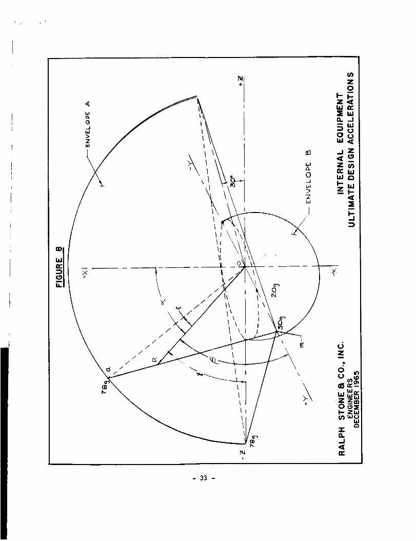
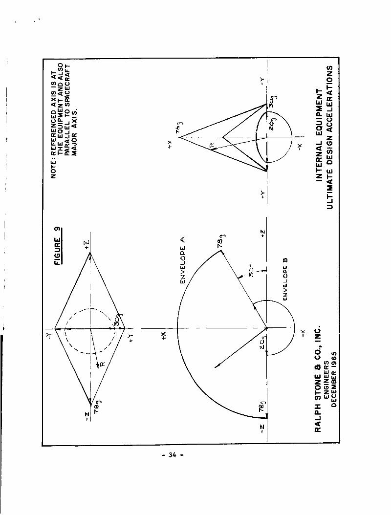
The most severe dynamic load, which the box must be designed to with-
stand, was defined by Apollo environmental specifications and interface struc-
tural documents as an ii millisecond impulse of 78 G peak amplitude (see Figs.
8 and 9) applied to the box support frame. The interfaces between the ship's
structure and the box frame have been established at four specifically desig-
nated points in the mid plane_ of the box envelope.
Actual interfaces were defined by Command Module and LEM interface docu-
ments to consist of 0.375 in. diameter pins and pin receptacles compatible with
the frame configuration.
The dynamic response of the box was therefore directly dependent upon the
structural characteristics of the mounting system and upon the mass of the
box and its contents. The maximum weight of a single container including its
contents was defined by interface documents to be 50 lb.
An initial study of flexible shock mounting systems was conducted to
determine whether container acceleration could be reduced below the 78 G peak
acceleration. Two different conceptualmodels of the dynamic system were con-
sidered: (a) the container and contents as an elastically supported single
mass system; (b) the container and contents as an elastically supported mul-
tiple mass system.
The term "elastic supports" in this context includes both linear and non-
linear springs. In addition, the effect of viscous damping was consideredt
in case (a). Significant features of this analysis are outlined uL_ _L_= full
owing page. Fig. I0 shows the model for the single mass system, consisting of
a rigid mass, m, representing container and contents, connected by an elastic
spring to a base, s, representing the support frame. The possible inclusion
of a viscous damping system in parallel with the spring is also illustrated.
The base is subjected to the 78 G impulse shown in Figs. 8 and 9.
- 32-
i
+
o)
uJ_
d
uJ W• zoo
ZwO_wU
T
J
- 33 -
01-_,, z__n,,
,nou _ 0--ZW
,.,._ ..........
w _oz Z I--
il l
_-_._ _.- .
l_ I'-!
4-4-
o..J
_: " tO O_I
I
× d' Z
m
c_
f,_w w
Z ,r_o,.-I
n,,
- 34 -

R R////
_ k2
J, U _-'-_ RI _ U
Figure i0. Force-Deflection Characteristics
of Mounting System (k = spring constant)
The impulse considered was a half sine wave of 2td equal to 0.022 sec.
The quantities y and Ys represent mass deflection and base deflection, res-
pectively, from the equilibrium position.
The differentialequatlon describing the dynamic resposes of such a
system was represented as:
R c {:+ _sO fa(t) = 0_+N+N
where U
r =
c =
Ys =
fa_j =
Y " YS
spring force at any value of u
damping coefficient
measure of impulse amplitude
impulse as a function of time
Note that this is sin (286t) for 0 _ t _ td, and 0 for t _ td.
Spring force was considered .to be either linear or non-linear, as shown in
Fig. ii.
- 35 -

It is recognized, however, that the foregoing analysis is largely
theoretical, while actual shock mount design is essentially an empirical
art dependent upon comprehensive dynamic tests. For this reason, the proto-
type box is designed to accommodate tests of flexible mounting devices if
required to establish final proof and flight hardware design criteria.
-37 -

PARTIV
SEALSELECTION
INTRODUCTION
Applications for high vacuumseals in configurations approximating thoseof the sampleboxesmaybe found in existing laboratory apparatus and herme-tically sealed flight-weight hardware. The latter designs are characterizedby small, closely-spaced bolts on a clamping flange around the seal perimeter.This provides uniform, high compressionunit loadings, butwith a slight _attendant weight penalty.
The seals for conventional laboratory high-vacuumapparatus are critical,since seal leakage detracts from the capacity of a pumpto scavengegasmole-cules from the test part or materials. Becauseof this, laboratory equipmentusually employswide, heavy flanges with multiple tie-down bolts to apply highunit loading uniformly over the length of the seal. Under these circumstancesit is possible to establish an efficient mechanical bond utilizing malleablemetal gaskets having very low outgassing rates.
The lunar samplebox is a passive or unpumpedvacuumchamberin whichseal leakage or gas diffusion would result in vacuumdegradation and serve asa potential source of samplecontamination. The fact that the box is a flight-weight container in which tare weight detracts from the quantity of returnedlunar material further differentiates the problem from conventional laboratorypractice, where the weight of the gland and its clamping devices are of littleconsequence.
The seai under discussion in the paragraphs to follow is the trans-earthor return seal. The selection of materials for this seal wasmadesomewhateasier by the fact that the tear-away outboundseal will be applied while thebox is at high vacuum,preventing oxygenor other potentially deterioratingsubstancesfrom being able to contact the return seal material or gland wallsprior to opening on the lunar surface.
CANDIDATE SEALS
Vacuum technologists have at their disposal a wide variety of proven con-
cepts ranging from ceramic and epoxy potting techniques for permanent joints
to metallic and elastomeric crush gaskets for removable ports and penetrations.
The philosophy of the seal selection program was that existing designs would
be examined first to determine their suitability to the objectives of the
box design.
- 38 -

As previously indicated, certain seals commonly used in pumped systems
were unsuitable for passive vacuum use because of relatively high outgassing
and gas transmissibility characteristics. The following paragraphs deal only
with the more promising candidates on which detailed studies were accomplished.
Metallic Gaskets
Crush gaskets of copper, aluminum, and gold are often employed in labo-
ratory test apparatus to produce vacuum seals. The most effective are capable
of applying one to two thousand pounds squeeze per lineal inch, crushing the
malleable seal material into the interstices of the mating surfaces.
At first rejected because of the weight penalty implied by supplying
uniform high unit loading, the concept was re-examined using the wedging
action of an inclined gland wall to provide the necessary crush loading for
a gold gasket. To avoid the addedweight and complexity of internal hardware
to apply sufficient lid loading, a pry-bar was considered. A rim around the
edge of the box provided the force reaction point and served to detent the
lid in place once sufficient crush action had been attained (see Fig. 12).
Seal integrity depended largely on the evenness of loading, which is difficult
to control. Also the pry-bar lld attach system implied added demands upon
the astronaut's time and physical resources.
While the wedge crush design avoided some of the characteristic weight
and complexity disadvantages attributed to standard laboratory configurations,
the high unit loading necessary to deform the gold was transferred to the _
opposite gland wall, making the design potentially susceptible to cold weld-
ing. Numerous research programs are currently active to determine the con-
ditions under which cold welding occurs ina vacuum. The diversified nature
of these programs suggests the magnitude of uncertainties still associated
with the problem, and the prospect of prematurely welding the lid at random
locations prior to affecting a vacuum seal became a major design concern with
the crush gasket approach. In addition_ the susceptibility of the design to
leakage by excessive contamination or accidental surface damage was considered
a major deficiency.
For the high unit load seal approach various schemes were investigated
to relieve the astronaut of excessive manipulation of tools or hardware.
Among these were rotating cams and inflatable balloons or bellows actuated
by a small compressed gas cylinder. While the designs had merit, each added
an element of uncertainty to the question of overall seal reliability, often
contributing potential mechanical problems such as cold welding or differen-
tial thermal expansion which appeared to outweigh their advantages.
- 39 -

(
- 40 -

Foil Seals
A second attractive seal design evolved fromstudles of various methods.
of sealing the inner foil bags (see Part V, "Packaging Studies and Special
Purpose Inner Containers"). It became apparent that the characteristic of
cold welding In vacuum, which was detrimental in the case of the crush gasket,
might be made to work advantageously in various forms to seal layers of foil.
The application of this principle to the primary vacuum seal was first prQ-
posed as a redundant backup, using the wedging action of the previously
designed gasket seal (see Fig. 12, lower inserts) to effect a crush bond
between layers of foil.
A common laboratory technique for vacuum sealing of copper tubing is to
cut it with a blunt-edged shear. Several experiments were successfully per-
formed demonstrating this technique on a much smaller scale using .001 in.
copper and aluminum foil. While encouraging, the results showed the vulner-
ability of the approach to any type of physical stress, the bond between the
loll layers being fragile. In addition, the surfaces, though not required
to be free of oxides or chemlcally clean in the case of the shearing seal,
nevertheless had to be free of dust or other gross physical impurities.
It was concluded that, while the approach would be pursued in the case
of the inner foll bags, its susceptibility to failure due to contamination
and vulnerability to accidental damage made it impractical to consider
further as a backup seal for the boxes.
Elastomeric Seals
By far the easiest approach to the sealing problem would have been
to select one of the conventional elastomers now in use for pumped vacuum
systems and attempt to protect the interior of the box from seal outgassing
and gas diffusion.
The more attractive features of the elastomeric seal include relatively
low susceptibility to imperfections, low unit loading requirements, and a
wide choice of available standard sizes and materials. The possibility of
using elastomers received considerable design attention during the period
when a foil backup appeared to be a practical means of eliminating outgassing
products from the box interior (see preceeding section).
In this connection, the use of two O-rings, while providing redundant
protection against catastrophic seal failure, was considered relatively in-
effective as means of improving vacuum. The double seal has often been used
where either the guard vacuum between the seals is large, or where a separate
pumping system can be utilized to draw off leakage and outgassing products
- 41 -

from the guard vacuum space. Since neither of these features could be in-
corporated in the sample container, the sealing effectiveness of para]_l
elastomers was considered to approximate that of a single O-ring.
Though discarded for the primary vacuum seal, the elastomer was re-
considered for the secondary or redundant backup seal. Referring to the
previously described design goal (10-2 torr) for seal redundancy, which
eliminated the hard vacuum requirement, the elastomeric seal appeared to
be an optimum choice as a barrier against gross contamination. In this
regard, fluorocarbon is relatively non-compliant, requiring high unit load f
ing and considerable design finesse to achieve an effective seal throughout
its length.
FINAL SELECTION (INDIUM-SOLDER PRIMARY SEAL)
Examinatlonsof the types of seals commonly used in vacuum practice
revealed continued reference to indium as a practical gasket material.
Being considerably more malleable than gold, it flows easily into inter-
stices, and surface imperfections. This feature was at first considered to
be its most attractive attribute, and it was studied for adaptation to the
then existing crush gasket design. It later developed that its low (330°F)
melting temperature might be utilized to advantage for producing a seal
requiring little effort on the part of the astronaut.
An examination of the seal revealed certain design uncertainties in
its application, yet the prospect of achieving near-zero leakage made the
risks appear minimal.
Design Configuration (Reference Fig. 13)
The indium will be molded in place in the female (lower) gland to form
a cavity. At the bottom of the indium space are two 1/16 in. diameter elec-
trical heater units connected to a receptacle _n the front of the box. The
male, which is connected to the lld of the container, is designed to accom-
modate the redundant elastomeric seal, yet to remain flexible so as not to
transmit lid deflection forces to the indium. Both male and female seal
members are protected by a film of fluorocarbon to help protect them from
accidental damage and assure against unwanted sticking during the period of
vacuum storage before use. The protective fluorocarbon film will also reduce
the exposure of the seal to contamination by rock particles and lunar dust
and will protect the metallic surface until the last possible moment before
replacing the box lid.
- 42 -
I

FIGURE 15
OUTBOUND COVERSPACER
FLUOROCARBONPROTECTIVE FIL M
NOTE,.
SEAL SHOWN WITH OUTBOUNDAA, op ...._,uv_ _'Au_ AND PROTECTIVE
FLUOROCARBON FILM IN PLACE.INBOUND CONFIGURATION HAS
ICOVER DROPPED I/8", SPRINGILATCHES ENGAGEDI O-RING
IN CONTACTI INDIUM MELTED
J
I
RALPH STONE a CO., INC.ENGINEERS
DECEMBER 1965
REDUNDANTELASTOMERIC SEAL
INDIUM (SHOWN BEFORE
MELTING)
SPRING LATCHES
HEATERS
EFLON HEAT SHIELD
SEALCONFIGURATION
- 43 -

To apply the seal a power source must be connected to the electrical
receptacle on the front of the box and held for approximately one minute.
A signal light will then indicate the seal has melted at two separate loca-
tions and is ready for cooling. It is estimated that five minutes will be
required for the seal to solidify in sunlight and two minutes in shade.
Comparison With Design Goals
The following sections compare the optimized indium seal to the project
design goals outlined in Part I. In some cases, an accurate appraisal of the
compliance of the seal to these criteria will be not possible until after the
prototypes areevaluated under simulated lunar environmental conditions.
Leakage. - A properly seated indium seal is expected to approach zero gas
transmissihility. Surface outgassing should approach that of the adjacent
stainless steel surfaces. Preliminary tests completed for this contract de-
monstrated that such leakage goals were realized in the laboratory.
Ease of application. - As in any seal configuration, the astronaut must
first tear_ay the protective fluorocarbon shields. He must then (i) replace
the lid, (2) level the box, (3) plug in the electrlcalconnection, and (4)
press the switch in the connecting cable. When the signal on the front of
the box lights, power should be disconnected and the seal allowed to cool.
Mission compatibility. - The acceptance of indium as a primary seal
material has not aroused serious concern to date in the scientific community
except to the extent it might contain impurities such as lead. Experiments
with 99.9Y% pure indium were performed in which the material was heated for
several days at 500oF without depositing detectable contaminants on the sur-
face of a glass-liquid nitrogen trap. However, on being raised to 700°F at
2 x 10 -8 tort, a faint deposit was picked up after 12 hours.
Protection against this possibility takes several forms: (i) the flight
hardware will contain the purest form of indium attainable, monitored from
its point of origin and specially packaged to preserve purity; (2) the indium
and seal gland will be subject to the same thorough precleaning under heat
and vacuum as the rest of the container, prior to electron-beam welding the
outbound seal strip in place; (3) the total heat cycle is not expected to be
more than 7 minutes including cooling time; (4) the top of lthe gland is gas-
keted so as to provide a trap for containing and condensing vapors; (5) the
vapor pressure of indium is approximately i0 -I0 torr at 700OF, a 400OF safety
margin over that temperature necessary to melt and form the seal.
- 44 -

Should evaluations of the prototype hardware reveal these features to beinadequate, a special thin-film protective shroud of laminated aluminumfoilwill cover the tops of all storage canisters. This shroudwill provide alarge area for heat dissipation andcondensation of indium vapors.
Contamination. - Assuming problems having to do with seal surface weft-
ability are overcome during manufacturing and subsequent processing, the
contamination source of greatestconcern will be that introduced on the lunar
surface. As described in the "Design Configuration" section, a protective
fluorocarbon film will be installed over the seal glands at the time of box
manufacture and retained until just prior to resealing on the lunar surface.
Even with this provision, there is a strong possibility that lunar dust, if
it is present, will be attracted electrostatically to the box. Because of
the high specific gravity (7.3) of indium, most of the dust will float quickly
to the surface. The probability that sufficient contamination will occur
during the short time between removal of the fluorocarbon caps and activation
of the seal to interfere with the wetting characteristic of the melted indium
is considered slight. In laboratory experiments, the tendency was for conta-
mination to form a surface layer of slag, leaving the pure indium-solder ma-
terial beneath. Withthe 0.2 in. depth of penetration designed for the male
member, careful astronaut closuretraining should minimize the lunar dust
problem.
Weight. - The weight of the indium is an unattractive feature, approxi-
mately 0.85 ib being required to fill the gland. However, because the indium
seal does not require large compression forces, weight was saved in both the
male and female gland assemblies, making the overall design weight competitive
with other concepts.
Complexity. - The female member of the seal assembly is a simple U-shape.
It does not require high surface finish or close tolerance for proper operation,
and is probably the least susceptible to malfunction by damage of any of the
configurations studied. The male, on the other hand, is designed to be flex-
ible, minimizing forces transmitted from the lid into the indium. It is
therefore more susceptible to damage, and a protective skirt has been provided
around the_erimeter of the cover, extending below the seal tip. Again_ th_
fluorocarbon cap covering both seal members will also be useful for protection
against accidental damage.
- 45 -
P

Disadvantages
Preliminary laboratory tests and discussions with various indium users
have revealed certain shortcomings of the material as a seal. In evaluating
these, design judgment was required to determine whether these adverse cha-
racteristics would pose problems in the one-shot application under study,
since most experience involved designs intended for continuous or repetitiveseal use.
One difficulty with indium is in preparing gland surfaces to ensure
proper wetting. Various users report problems ranging from amalgamation with
gold or silver coatings to a need for elaborate surface preparation proce-
dures such as hydrogen firing to ensure wettability. Most report that with
a hyper-clean surface, that is one cleaned mechanically of all dirt, oil,
oxides, or other impurities, little wetting difficulty was experienced with
indium. Since such precautions will be a normal consequence of eliminating
contamination from the box regardless of what seal configuration or material
is used, the problem may not be of practical significance in this application.
A second disadvantage is the tendency of the material to form surface
oxides. As a precaution against this, it is expected that all of the box
manufacturing operations subsequent to final cleaning will be done either
in an inert atmosphere or under vacuum, including the molding of the indium
in the female gland. Immediately following these steps, the tear-away out-
bound seal strip will be welded in place in the vacuum chamber, not to be
removed until on the lunar surface. The seal will thus be protected from
oxygen or other outside contaminants.
A third disadvantage lies in the extremely weak physical properties
of indium. Tensile strength in the order of 380 psi and compres_on of 300
psi make the material structurally unattractive. For that reason the lid
has been designed as if it were a hinged plate, resting on top of the inner
wall of the seal cavity with the seal carrying no moment. The male seal
gland is a straight, flexible section of 0.010 in. stainless steel. Stresses
at the edges due to atmospheric loading on the lid are carried by the latching
system, preventing edg_ rotation and attendant seal stress.
The box will be sealed while still exposed to the lunar vacuum and
subsequently exposed to external pressure only. However, as described in
Part If, a pressure-relleving port will be provided to protect the structure
against possible build-up of internal pressure from sample 0utgassing orsublimation.
- 46 -

Another problem is the low thermal coefficient of expansion of indium.
To help ensure against separation as tbe indlum cools, gland walls were
designed to be flexible by using 0.020 in. stainless steel. Laboratory
tests wlth similar configurations were successful.
A final problem is that the indium seal we have _oposed representsan advanced application that has not bean commonly employed in high vacuumsystems. However, current test experience and data indicate the aforemen-tioned negative factors can be surmounted in the prototype box design concepts.
- 47 -

PART V
PACKAGING STUDIES AND SPECIAL PURPOSE INNER CONTAINERS
CANISTER CONCEPT
Sample and Container Advantages
A single, uninterrupted volume within the sample box, while providing
the most flexible overall use of available space, places the entire burden
of sample protection on the flexible packaging bags. The prior study con-
sidered employing a series of truncated baffles lining the sides and bottom
of the box to protect the smaller samples. The larger rocks were to be
supported by the baffle edges in the open center cavity. One difficulty
with this design was that the center cavity had to be sized to accommodate
the largest anticipated sample, requiring that additional packaging material
be placed around rocks of lesser dimensions to prevent excessive movement.
In addition, the large center cavity afforded little intrasample protection.
The removable canister concept evolved during the present study avoids
these difficulties. First, it affords maximum physical protection to indi-
vidual samples and protects the inner walls of the vacuum box from puncture
by sharp rock projections during periods of impact or vibration. Second,
storage space for larger specimens may be arranged and altered as required
by the astronaut byremoving various canisters.
Sizing and Configuration
Tha basic canister sizing criterion was to provide suitable protection
for small geologic hand specimens. Secondary criteria were (i)the canisters
should be modular for interchangeability; (2) rocks too large to be placed
within a single canister should be accommodated by removing two or more
_anisters to orovide _ l_g_ _-,,_y; o_A t_ --_ _. - .............. ,_s large Lu_k_ should be sepa-
rated from the box walls by at least one row of canisters.
Considering the plan view of the box (reference Fig. 14), two rows
of canisters would not meet the latter design criteria. Three rows provide
the desired outer wall protection, but samples larger than I/3 the width of
the box (3½ in.) would require removal of one or more canisters from the
outer rows, exposing the vacuum Jacket to potential hazard. The four row
configuration allows two inner rows, or slightly over 5 in.,to be removed
if required for larger rocks. With five rows, the modular canister size
drops to approximately 2 in., which was considered too small for practical
sample storage.
- 48 -
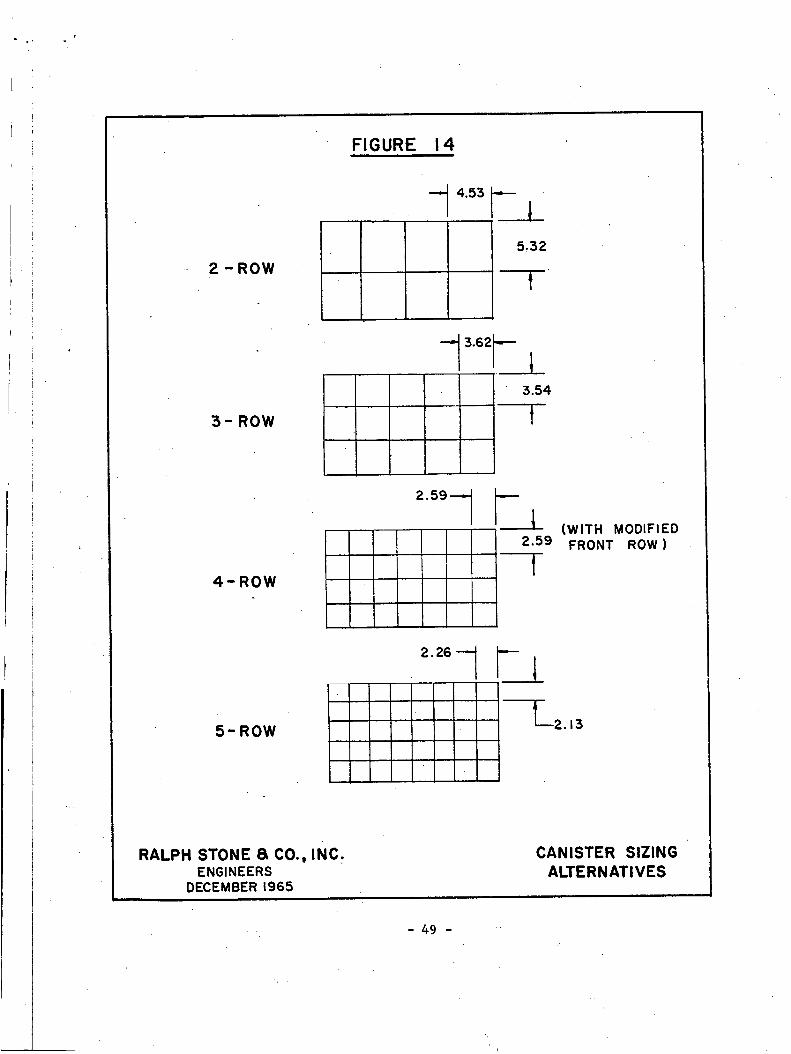
2 - ROW
3- ROW
4-ROW
5-ROW
RALPH STONE 8 CO.o INC.ENGINEERS
DECEMBER 1965
FIGURE 14
4.55 --,,--
15,3_'
3.54
2.59---_
2.59(WITH MODIFIED
FRONT ROW )
CANISTER SIZING
ALTERNATIVES
- 49 -

The four row configuration thus is optimum. Allowing 0.010 in. clearance
between canisters, the row at the box front is 2.93 in. wide and the other
three rows are each 2.59 in. wide.
To provide bottom protection against penetration by larger rock specimens,
the ten center canisters occupying the aforementioned large sample storage
position have each been divided into separate upper and lower canisters, the
upper being 5.01 in., or 3/4 of the total available storage height, and the
lower 1.67 in., or 1/4 of the height. The lower canisters have a 0.30 in.
flange around their opening to form a ledge for the large rock samples to
rest upon, minimizing cutting and abrasion problems.
Loading Sequence
Fig. 15 illustrates the preferred loading arrangement for various pay-
loads. In general, it is considered more desirable to have a few filled
canisters than many which are half empty, so that vertical movement of the
cargo will be minimized. The cargo should be distributed so that the corner
canisters nearest the mounting pins are loaded first, followed in turn. by
the end and side canisters. The center rows should be reserved for final
loading and/or large specimens.
FLEXIBLE BAGS
Materials
The previous design study recommended multiple laminations of thin,
flexible material to reduce the possibility of gas diffusion or contamination
transmittal through the bag walls. A successful material consisted of four
0.0005 in. laminations of alumlnum/polyester film/polyester film/alumlnum,
making a 0.002 in. sandwich. The Manned Space Science Lunar Working Group
at Falmouth, Massachusetts, recommended in July, 1965, that polyester film
be eliminated from the sample bag and TFE fluorocarbon substituted in its
place. Although the manufacture of prototype inner bags was not included
with the current work, investigations of manufacturing problems showed that
a two layer lamination, using an inner liner of aluminum loll and an outer
layer of fluorocarbon film, is a practical combination. The aluminum liner
provides an optimum material for direct contact with the sample, while the
outer fluorocarbon layer is expected to prevent the bag s from sticking to-
gether in vacuum. As recommended in the prior study, each bag should be
serially numbered to enable the astronaut to record surface conditions and
other acquisition information pertinent to each sample.
- 50 -

Configuration
Packaging studies performed under the previous study contract indicated
that the minimum practical bag size for astronaut handling was 3 in. in dia-
meter at the opening by 5 in. in length for small samples. Bags 7 in. in
diameter by 9 in. in length for larger rocks were recommended. Further
recent packaging studies with these configurations showed that excessive bag
tare weight would result unless each bag were filled to near capacity. Thus,
sample mixing within the same bag would be required for specimens under 2½ in.
in diameter which is undesirable for certain post-mission scientific evalua-
tions.
An alternate solution would be to provide small bags in the 1 to 2 in.
size for pebble or marble-sized samples. In the previous study this was
avoided because the astronaut could not efficiently handle bags of this size
and because several hundred would have to be filled to make efficient use of
the available storage volume. Under the current contract, a seml-automatic
means of efficiently accomplishing this type of packaging has been stu_ed,
as described below under "Bag Dispensing Systems".
Seal Concepts
The flexible inner containers are adaptable to two basic sealing
approaches. Since the recommended material has an aluminum foil inner liner,
a cold weldlng or fusion bonding seal can be considered. Also, using a
dispensing tool with resealing capabilities_ a crimp-over or canning tech-
nique: might be employed to produce more positive seals.
The laminated fluorocarbon and aluminum material also lends itself to
various plastic seal configurations. Among the most promising to date has
been a conventional interlocking zipper, which is convenient to apply and
relatively tight up to i00 tort differential pressure. Considering the bag
seal as a molecular migration barrier between differential vacuums of 10 -5
to 10"9tort, the zipper configuration should be effective. On the other
hand, if the design criterion is to protect the samples with an effective
redundant seal in the event the primary box vacuum fails, a more positive
seal would be required.
Bag Dispensing Systems
The design of the flexible containers and the choice of sealing methods
are both dependent upon the time and dexterity constraints of the astronaut.
Without a semi-automatic bagging mechanism the larger, less efficient bags
recommended in the previous study appear to be optimum.
- 52 -

Fig. 16 shows a design for automatically opening and resealing small
(2 in.) flexible bags. Each squeeze of the handle trigger advances a newlyopened bag to the filling hopper position, where sample material is droppedin by the astronaut. The next trigger pull advancesan empty bag to thehopper position and seals the filled bag between two crimp-seal rollers.
A I in. continuous strip along the top opening of the bags serves as aguide for the sample material when under the bopper and protects the critical
sealing interface from dust and debris. The strip is torn away from the bagmouth along a perforation Just before entering the crimp-seal roller closure.
GAS SAMPLING CONTAINEK
Materials
Highly polished 410 stainless steel is a recommended material for bake-
out and vacuum degasslng to minimize residual molecular gas traces from _the
interior of the container intended for transporting samples to be used later
for gas analysls. Among the available candidate seal materials, indium iS
attractive from the standpoint of being (1) consistent with the existing box
seal and (2) readily deformable as a crush gasket.
Configuration
A configuration design is shown in Fig. 17. The overall assembly is
2.5 in. in diameter by 6.0 in. long. For outbound transportation, the lidand body are loosely packaged in foil untll ready for use. After strippingaway the foil, the two halves are brought together and twisted to exert the
necessary crushing force on the gasket. The ball at the end of the cover
assembly transmits axial force from the screw without causing rotation against
the gasket surface.
The gas sampling port in the recessed hole in the base of the container
is designed to accept a sampling probe from the mass spectrometer. A loll
diaphragm, ruptured by the insertion of the analyzer probe, is used to ensure
positive sealing of the container.
- 53 -

hlli:
m
14.
e_(nZn-<I w
- 54 -
O0
m
Z
bJ
.J
n,"

FIGURE 16-B
-SWITCH
CRIMP-SEAL ANDDRIVING ROLLERS
MOTOR
o:sPosi_ 'LOADING
s..oupI
1
h
--BAG IN LOADING POSITION
..... _:_'_'.X ',
•....__-i-,,:_,-i---,--,F_,--F_i i .. I p" _ _" :
LOADING .__/ L GUIDE RAILS FORHOPPER LOADING SHROUD
RALPH STONE & CO.,INC.ENGINEERS
DECEMBER 1965
BAG DISPENSING ANDRESEALING DEVICE
- 55 -
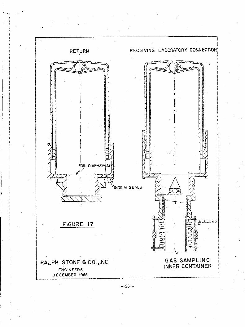
I
RETURN
1_1 FOIL DIAPHRAGM
FIGURE 17
RALPH STONE I_ CO.,INC
ENGINEERS
DECEMBER 1965
RECEIVING LABORATORY CONNECTION
S E ALS
_ELLOWS
GAS SAMPLING
INNER CONTAINER
W-
-.56 -
i

• PROTOBIOLOGICAL SAMPLING CONTAINER
Requirements
The protobiological sampling container must be adaptable to a system of
obtaining material from 6 to 18 in. beneath the contaminated lunar surface.
Every precaution must be taken to ensure aseptic handling of the container
before, during, and after the sampling operation. Thirty to fifty samples,
each I to 5 grams in weight, are desired. The seal must provide an effective
barrier agaihst transmission of contaminants from within or without and must
be protected against pollution by the astronaut's suit, gloves, or LEMwastes.
Dispensing Tools
Because of the necessity for isolating the sampling operation, the design
of the sampling container cannot be effectively isolated from the dispensing
tool. A concept for such a combination is shown on Fig. 18, depicting a
double-barreled probing tool in which the right-hand barrel dispenses empty,
clean sample cartridges, while the left-hand barrel returns filled and capped
units. The pointed end of the probe remains closed until the desired depth
has been reached, at which time a trigger mechanism retracts the probe cover
and permits the empty cartridge to be pushed forward for filling. This action
also scrapes aside any surface contaminants left on the probe tip, exposing
only the virgin lunar material.
The design of the cartridge assembly must be predicated almost entirely
upon the probing, retract, and capping action occurring at the probe tip. A
slngle-walled cartridge would not be acceptable, because it could be contami-
nated during the retract cycle by debris from previous probings. The double-
walled cartridge, enclosed by a foil diaphragm, avoids this by keeping the
inner sampling unit covered until the last possible moment, whenthe probe
cap is retracted (see Fig. 19).
Having been thrust through the foil diaphragm into the lunar material,
the sampling unit is then withdrawn into the outer cartridge and held in an
inverted position until capped. In this way the inner sample container does
not contact at any time the contaminated elements within the probe tip, see-
ing only the inside of the outer cartridge.
The sample container cartridges are designed with an internal flap or
iris which serves as a check-valve against loss of material during the re-.
traction and capping operations. An indexing lug on the side of the container
- 57 -
!;

BARREL TELESCOPE
CLOSED OVERALL
DIMENSION 15" /
/ ......
////..__._ UN,TCOULDLOADA.D//// UNLOADTHRUTUBULAR
MAGAZ,NES
iiii}:,o 'a
f
EMPTY CARRIER LOADED CARRIER
IS PLUGGED INTO IS WITHDRAWN AND
MOVES TO RETURNSTRATA
CHAMBER
'_ !2
CARRIER IS CAPPED AND
READY FOR RETURN
FIGURE 18
RALPH STONE 8_ CO., INC.ENGINEERS
DECEMBER 1965
SCHEMATIC
BIOLOGICAL SAMPLE CONTAINER DISPENSER

k
I:
I,li
ii
MOVEMENT SEQUENCE
WITHIN PROBE
FIGURE 19|J
(_ ADVANCING CARTRIDGE
- (_ INITIAL POSITION
(_ EMPTY CARRIER PLUNGEDINTO STRATA
(_) LOADED CARRIER • WITH-DRAWN AND CAPPED
(_ LOADED CARRIER INRETURNCHAMBER
\
II_
II
SEECARTRIDGEDETAIL
ASEPTIC,SHROUDRUPTURED
CARTRIDGE
-EXTENSION AND
RETRACTING LUG
RALPH STONE 8= CO.,INC.ENGINEERS
DECEMBER 1965
ASEPTIC SAMPLE
CARTRIDGE
- 59 -

allows the operation to be oriented to lunar north or any other desired refer-
ence direction.
Upon further retraction of the probe the cartridge unit is then ejected"
into the left-hand return barrel in a manner similar to the action of an
expended rifle cartridge. At the same time, the pointed cap over the open
sampling port is again closed. The next triggering operation, during which
a new sample cartridge is thrust forward, also presses the filled unit into
its capping mechanism. When the probe is retracted, the capped container moves
up the left-hand barrel just ahead of the incoming uncapped, newly-filled
cartridge.
While external power is not a design necessity, a low-amplitude vibrator
working from a battery in the handle would help keep the device free from
the effects of accumulated debris in the probe tip and would be of modest
assistance in penetrating surface materials other than hard rock which could
not be bored with this configuration.
STORAGE PROVISIONS
Jl '
The canister concept is readily adaptable to the storage requirements of
the various speclal-purpose inner containers discussed in this section. For
instance, the smaller flexible bags are intended to be inserted directly into
the canisters. For larger samples, selective removal of canisters serves as
a means of sizing the storage cavity.
The former storage plan for gas sampling containers involved clips on
the side walls of thebox. This concept was not consistent with the modular
canister packaging system, and the alternative was to treat the small gas
sample inner containers as if they were rock specimens, packaging them with-
in flexible bags and storing them in the modular canisters. The inner con-
tainers will thus receive maximum physical protection as well as redundant
vacuum sealing, while not requiring special clips or storage provisions.
Similarly, the small protobiologlcal cartridges can be stored within _exible
bags and placed in one of the modular canisters.
- 60 -

iL
fi
J
!
t
PART Vl
PROTOTYPE HARDWARE FABRICATION
INTRODUCTION
Two prototypes of the sample container and internal canisters were fab-
ricated to permit subsequent tests and evaluations of critical design features.
Investigations leading to theconstruction of the prototypes covered all facets
of configuratlonal, structural, seal, handle and latch, sample protection,
and special purpose appendages described in Par_s II, Ill, IV, and V. Special
purpose inner containers, while included in the design studies, were not a
part of the prototype fabrication program.
Inasmuch as minimum design development and release time was estimated to
be 3% months and manufacturing 2% months, particular emphasis at the beginning
of the current 6-month phase was placed on those nmterials and processes al-
ready developed. For example, when it was determined that honeycomb construc-
tion would be an optimum structural choice, various alternate materials, core
depths, cell sizes, and skin thicknesses were evaluated in terms of meeting
technical as well as schedule commitments. The choice of stainless steel
honeycomb was strongly influenced by the latter consideration, yet other att-
ractive alternatives were noted and parallel efforts made to determine the
best nmnufacturing system and the minimum time needed for development. One
such investigation resulted in recommendations to NASA for an optimized unit
possibly weighing 40% less than the initial prototypes described in the foll-
owing sections. Evaluations of these alternatives are expected to continue
and be completed prior to the release of manufacturing specifications for
proof and flight hardware.
The following sections discuss the general design philosophy and manu-
facturing techniques used for producing the prototype hardware. Drawings and
a list of materials are available under separate cover, "Lunar Sample Container
Prototype - Drawing Supplements, containing specific engineering designs.
WALL CONFIGURATION
Honeycomb Configuration
The basic wall structural material was honeycomb fabricated of PHIb-TMO
stainless steel, initially fabricated of 0.020 in. face sheets (see chemical
milllng description in the following paragraph). Core thickness was 0.300 in.,fabricated of 0.002 in. PH15-7MO stainless steel loll in 1/4 in. cells. Braz-
ing was accomplished at 1800°F with 0.001 in. silver-lithium (99.8% silver,
- 61 -

0_.27. lithium) alloy.
200,000 psi ultimate.
The heat treatment condition was 170,000 psi yield,
Chemical Milling
Stress calculations for the stainless steel honeycomb walls showed that
0.005 in. wall thickness was adequate, but manufacturing and handling diffi-
culties with honeycomb of such thin face sheet gauge were considerable.
Therefore, it was decided to use heavier gauge material (0.020 in.) initially
and rely upon subsequent chemical milling for weight reduction.
A secondary advantage of the chemical milling process was that areas near
penetrations and points of load concentrationwere masked to retain the ori-
ginal 0.020 in. thickness which provided better local stress distribution with-
out the necessity of doublers or secondary structural members. In general,
0.5 in. borders were left around all attach points, utilizing a tapered edging
process to minimize notch effects.
Nominal thickness following
^^.+0.002ings as 0. uUoL0.001 in. depth.
chemical milling was speclfied on the draw-
FRAMING CONFIGURATION
The honeycomb panels were manufactured without edge members with the
outer face sheet extending 1/4 in. in all directions beyond the edge of the
inner sheet and core. The framing system was designed of square cross-section
tubes to which T-sectlons were tack-welded. All frame members and seal glands
were then Jigged to proper configuration, tack-welded, and vacuum furnace
brazed at 1800°F. Honeycomb panels were then inserted from the outside, rest-
ing both the inside and outside skins against surfaces at least 0.200 in. wide
towhich they were vacuum furnace brazed at 1450OF. Interior corner caps were
used for additional vacuum integrity at each 3-wall intersection.
: Framing details and dimensions may be found'_in the Drawing Supplement.
JOINING TECHNIQUES
The high temperature (1800°F) silver-lithium brazing alloy was selected
for the honeycomb panel manufacture as well as the basic framing_stem to
permit the use of a secondary, 1450OF brazing technique in joining the panels,
penetrations, and attachments to the box during a single final Joining
- 62 -
operatio n . A heat treat and aging (stress relief) cycle established by the
honeycomb manufacturer was used subsequent to brazing to provide the 160,000
psi yield and 190,000 psi ultimate strengths described in the design calcu-
lations. Vacuum weld repair subsequent to brazing was done with hell-arc
welding following helium leak detection techniques.
PENETRATIONS
Mounting point stress concentrations were minimized by placing stainless
steel plugs at the location of the mounting pin penetrations during the manu-
facture of the sandwich panels. The only other penetration into the vacuum
chamber provided on the present prototypes was the handle and latch mechanism
well which was installed with internal and external flanges brazed in place
during the overall box assembly.
HANDLE AND PIN RETRACTION MECHANISMS
The mounting pins on either side of the box must be retracted to permit
removal of the container. To achieve this, the handle assembly is first
pressed inward, then rotated. Detents are provided in both the mounting and
carrying positions. The unit was designed so that all rotating and recipro-
cating parts slideon fluorocarbon bushings with the exception of the rod
bearing ends whichare standard precision miniature bronze bushings.
The push rodswhich actuate the mounting pins were fabricated of alumi-
num, while the mounting pins are stainless steel to provide maximum shear
strength. The handle and most interconnecting parts were fabricated of hollow
aluminum to minimize weight.
Steel snap rings were used for retaining pin assemblies, while threaded
parts were assembled with lock-tight compound and lock washers. The handle
INTERNAL CANISTERS
' [
The internal canisters used for sample p;otection were fabricated of
6061-T6 aluminum, 0.015 in. thick at the upper edges, chemical milled to 0.005
in. on the side walls and bottoms. The chemical milling of the exterior sur-
faces of the canisters was done subsequent to forming and hell-arc welding.
The internal surfaces are smooth and free from projections which might snag
on the flexible sample bags.
- 63 -

SEALHARDWARE• !L
The female gland is a formed section of 0.030 in. PHI5-TMO stainless
steel. The i internal gland wall which supports the lid has a 0.060 in. fluoro-
carbon cap. The external wall has a 5° outward bend to minimize the danger
of cutting the redundant silicone rubber 0-ring seal.
The male_is a formed section of 0.010 in. PHI5-7MO stainless steel. The
heater unit consists of two parallel stainless steel tubes, 1/16 in. o.d. con-
taining ceramic insulation and nichrome resistance wire each producing slight-
ly under 5 watts per lineal inch. The total power of both heaters in parallel
is 800 watts. The connector is a standard AN series unit used on an interim
basis until the interface between the sample box and the LEM power cable has
been defined.
Dimensions and material specifications may be found in the Drawing
Supplement.
- 64 -

APPENDIXA
STRUCTURALCALCULATIONS
1.0 Material Properties - Stainless Steel PHI5-7MO
Ultimate Tensile Strength
0.2%Tensile Yield Strength
Shearing Strength
Elongation, % in 2 in.
Hardness,Rockwell
Modulus of Elasticity
Density (Solid Material)
= 220 000 psi
= 190 000 psi
= 6_%of Tensile Strength
= 5
= C45
= 30 x 106 psi
= 0.3 ib/in. 3
2.0 SandwichDesign
2.i Lid
2.1.i Primary Moment
To determine honeycombsection required, consider the lid as asimply supported plate under uniformly distributed load of 20 psidue to external pressure.
b_ : 18.91 : 1.65a ii .45
M : _qa 2
Mma x = 0.0908 x 20 x 11.452
primary= 238 in .-Ib/in.
at center of plate
(IA)
- 65 -

where _ = momentcoefficient
q = uniform pressure = 20 psi
a = short edge dimension = 11.45 in.
b = long edge dimension = 18.91 in.
A basic design objective was to minimize wall thickness to make
available maximum box volume. With core thickness of 0.3 in.
(minimum practical fabrication dimension), the maximum primary
bending stress in sandwich facings is
where
Mf
tft c
f = calculated stress
(2A)
M = bending moment
tf = • facing thickness
tc = core depth
For stainless steel facing of 0.006 in. thickness
f = 0.3 x 0.006 0.30Oin
= 132 200 psi #
Weight of basic panel t o.oo6in
The core density for stainless steel honeycomb is 8.3 ib/ft 3.
This is equivalent to 0.0014 Ib/in. 2 for 0.3 in. core. The
density of .......
2 x 0.006 x 0.3 = 0.0036 ib/in. 2
The density of the stainless steel sandwich
= 0.0050 Ib/in. 2 of panel
- 66 -

2 .i .2 Secondary Stresses in Lid
In addition to the primary moment, effects Of in-plane loads must
be considered. These loads are due to the pressure on side plates.
Taking a unit strip from the center of the box and considering it:
as a rigid frame with hinged lid supports under 20 psi exterior
pressure, maximum reactions on the lid may be calculated by the
moment distribution method. Horizontal components of the react-
ions will be equivalent to shear forces at the seal and in-plane
loading on the lid.
Fixed end moments
M
MAB = MBA
MBC = MCB
MCD = MDC
= _L 2 (3A)
I °- x 20 x ---7.002 = 82 in.-ib
i-f
= i----x 20 x 11.452 = 219 in.-ib12
= i___x 20 x 7.002 = 82 in.-ib12
Stiffness coefficient
KI
= L
I
7.00= 0.143 1
KBCI - 0.087 1
11.4s
Modified stiffness coefficient
K' 3AB = [ x 0.143 I =
IK'BC = _ x 0.087 1 =
20 psi
0.107 1
due to hinged end
0.044 1
due to symmetry
(4A)
(5A)
- 67 -

MOMENT DISTRIBUTION DIAGRAM
0.71 B 0.29
-82 2i9
-41
-68 -28
-191 191
8_--A,____HA-82
0
0.29
-2i9
28
-191
C 0.71
41
68
191
-82
82
0
D
MB -- HA x 7.00 - Ix 20 x 7.002
HA = 97.3 ib/in.
191 in.-ib/in.
This is the shear force at the seal or the in-plane loading at
the lid. For conservative design, the buckling strength of the
lid is calculated by considering it to be a simply supported
rectangular plate compressed by uniformlydistributed loads
of equal magnitude (approximately 90 ib/in.) in two perpendi-
cular directions.
Consider general biaxial compression buckling
where _ = Pdsson's ratio
s = core cell size
= 0.30
ffi0.25 in.
FORCE DIAGRAM
90 Ib/in(opprox)
18_91 in
TTI"TT
fx
fy =
D =
U =
G =
calculated stress :_
parallel to x-axis
calculated stress
parallel to y-axis
sandwich bending stiffness .
transverse shear stiffness
shear modulus of elasticity = 11.5 x 10⁶ psi
GC ! =modified shear modulus of
elasticity of core
• 68-

°" i
CORE
1"TTT
GENERAL
BUCKLING
y
Yi =
PC w =
Gc ! _-
fx =
f_
fx
_i - y+yz =
(6A)
(7A)
theoretical square cell
core _ensity
material density
core ribbon gauge
= •0.3 ib/in. 3.
= 0.002 in.
2tc' 2 x 0.002 x 0.3 (8A)Pc =
s 0.25
0.0048 ib/in. 3 = 8.3 ib/ft 3
[Oc'_l542.43 \_'cc/ g if Pc' < 1'6.7 ib/ft 3
1.54 x\u.J /
(9A)
48 _000 psi
90 = 7500 psi = fy2 x 0.006
bm
c
U
D
-- 38.2
G c' (c + 2tf) = 48 000 (0.3 + 2 x 0.006)
= 15 000 Ib/in.
Eta (c + if) 2
2 (1 - u 2)
(IOA)
_n _ lnu _ n nn_ /n _n_%_
2 (1 - 0.3 2)
= 9250 Ib-in.2/in.
b2U = 11.452 x 15 000
= _ _2 x 9250= 21.6
(hA)
(12A)
K x = 1.5 determined from empirical data
- 69 -

Kxcr = KxU = 1.5 x 15 000
--_- J2tf 21.6 x 0.012
= 87 000 psi
FXcr
Fxcr
= critical stress parallel to x-axis
= 190 000 x 0.6 = 114 000 psi
determined from empirical data
Margin of safety
Fxcr I 114 000= - = -1 = 14fx 7500
(13A)
Multiply primary moments by
I
i - f/fcr
as an estimate of secondary effects.
(14A)
I = 255 in.-IbMmax = 238 x i - 7500/114 D00
255 = 142 000psifm = 0.3 x 0.006
Combined stress due to moment and in-plane load
= f-m+ fx = 142 000 + 7500 = 149 500 psi
2.2 Bottom
Since the honeycomb plate is brazed to the frame, the examination
of the bottom demands more rigorous treatment due to boundary con-
ditions which are somewhere between simply supported and built-in.
For a conservative design for moment a simply supported rectangular
plate under Uniformly distributed load is considered.
- 70 -

Note that for fixed edges, Mmax = 0.08 qa2. This coefficient is
less than that for a comparable simply supported plate.
Dimensions are the same as those of thelid. Therefore, the pre-
viously calculated honeycomb section is adequate for the bottompanel.
2.3 Sides
Based on the same concepts, the stresses on the side plates were
calculated and the same honeycomb section was determined to be
adequate.
2.4 Local Behavior of Sandwich
2.4.1 Core Shear Properties
Isotropic square celled_honeycomb core is considered.
, f Pc' _i.34 Fsu •F s = 1.307 _'-_c/ c0.44
where
for Pc' < 18 ib/ft 3
FS! _=
FSU =
F s' =
design core shear strength
ultimate allowable stress of core
/0.0048_ 1"34 220 0001.307 \ 0.3 / 0.3 U-44
= 1920 ib/in./in.
(15A)
Shearing stress is assumed to be taken by honeycomb core.
Shearing force = Vma x -= 0.496 qa (16A)
= 0.496 x 20 x 11.45
= 114 ib/in.
Shearing •force per unit Area =
I= 114 x 0.3 x i
< 1920 ib/in./in.
- 71 -
Vmaxbc
-- 380 ib/in./in.
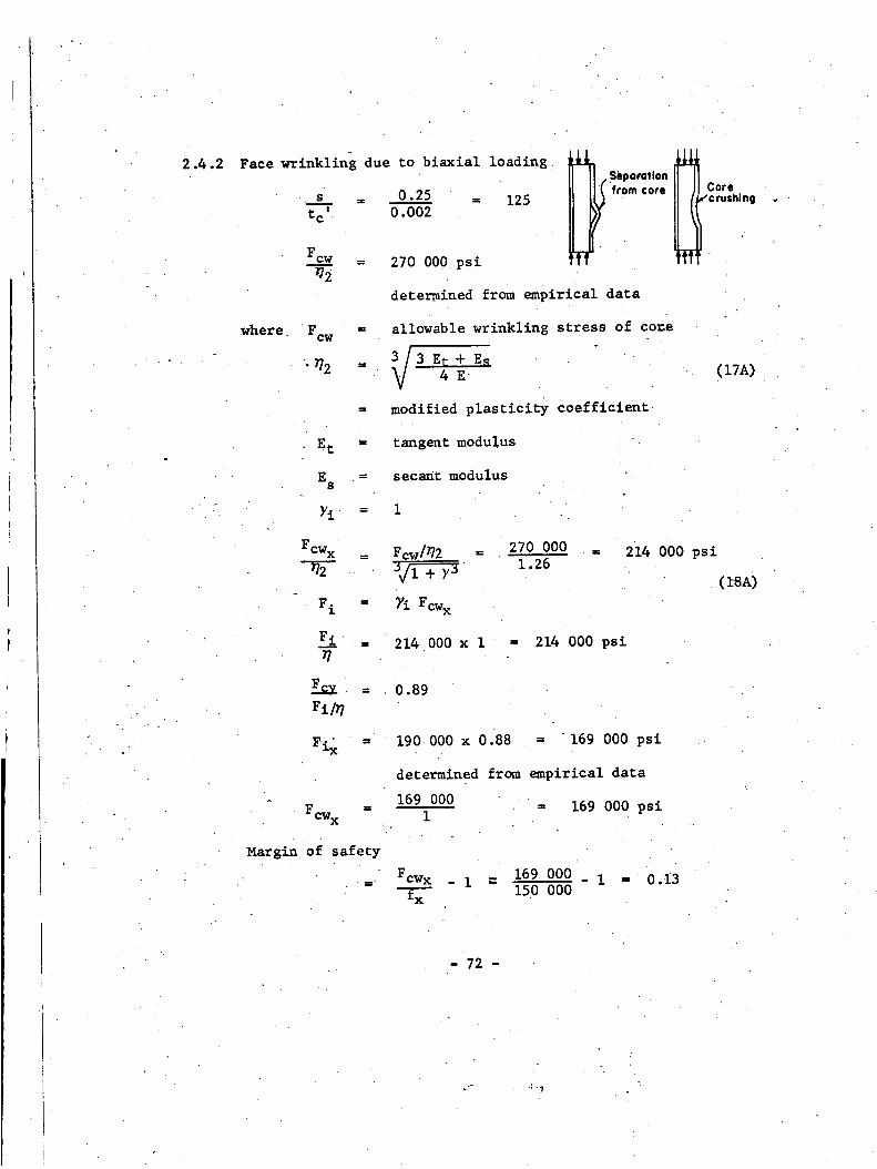
i,
II
1
I
Ii
2.4.2 Face wrinkling due to biaxial loading •
s = 0.25 = 125
tc' 0.002
Fcw = 270 000 psi92
determined from empirical data
Core_"c rushing +.
where. allowable wrinkling stress of co=e
/-_--_ E_ + Es3
V4E"
modified plasticity coefficient
(I_A)
E t
Es
Yi
tangent modulus
secant modulus
I
cw x
F i
F_i
l=
Fcw x
Fcw/_2 = 270 000
3_-_-_ 1.26
7i Fcw x
214 000 x I = 214 000 psi
214 000 psi
= . 0.89
190 000 x 0.88 ffi 169 000 psi
determined from empirical data
169 000169 000 psi
(_SA)
Margin of safety
Fcwx - i - 169 000
f--_ 150 000
- I = 0.i3
- 72 -
j_ •:. ?

2.4.3 Shear Crimping
s x tc = 0.25 x 0_002 = 0.0005
Gc' ffi 48 000 psi
Then the maximum allowable shear crimping stress in the direction
of the maximum principle stress is
ffi Gc' (c + 2tf) = 48 000 (0.3 + 0.012)
Fcsmax 2tf 0.012.(19A)
ffi 1 250 000 psi
Margin of safety
Fcsma x 1 250 000= - I ffi - i "ffi8215 000
fmax
2.4.4 Dimpling of Facings
Fc i ffi intracell buckling strength of core
Rxn + RyD = i for critical condition
2.4.4.1 For skin thickness of 0.006 in.
J
_k4
s = 0.3 ffi 50 > 15.63
_f 0.006
therefore
n = 3
_Honeycombtype core
Fc i
Fci_ -
64 000 psi
determined from empirical 'data0.006 In1-
190 OOO = .2.97i
64 000 . . ' u.o^_'OOin
• ii,'i
- 73 -
.v
(2oA)
(21A)
i
¢,

J°
I*
L.
LJ fX t combined stress (bending and in-plane load)
parallel to x-axis
fy ' combined stress (bending and in,plane load)
parallel to y-axis
Fci =
Ry =
Rx n + _n =
2.4.4.2
190 000 x 0.365 = 67 500 psi
fx' _ 150 000= 2.22
Fci 67 500
fv' ffi 2.22
Fci
2.223 + 2.223 = 22
For 'skin thickness of 0.020 in. (at edges)
ffi 0.___3 = 15 < 15.63tf 0.02
therefore
L_
F=__!
_15.63_ 22 Ci-f-) = 3.o9
390 000 psi
determined from empirical data
Fci/_
ffi 190 000 = 0.49390 000
Fci
RE
Pv
P_n+ PVn
ffi 190 000 x 0.945 = 180 000 psi
determined from empirical data
fx-- _ 150 000 , 0.833
Fci 180 000
= ffi 0.833
Fci
= 0.833 3.09 + 0.8303.09 = i.i
(22A)
(20A)
- 74 -

• i
• .
2.4.4.3 It is• recognized, therefore, that intracell buckling may occur
in regions of maximum stress. This does not constitute failure,
however, and is an indication of efficient design in this appli-
cation.
2.5 Interior Loading on Panels
Inner containers are allowed to collapse during shock load. How-
ever, the effect of contents on the bottom and side panels of the
container must be checked.
During the impulse of 85 G (78 G maximum plus any effects of elasti-
city of supports etc.) the load reacted by the panel due to the con-
tents under the above impulse is maximum, considering that 40 Ib
of samples are contained in the box.
Maximum load = 85 x 40 = 3400 Ib
Equivalent uniform distributed load on bottom panel is:
3400 = 15.7 Ib/in. 218.91 x 11.45
Note:
This provides a safety factor of 20/15.7 = 1.27 over design
for uniform pressure of 20 psi.
Equivalent uniform distributed load on front panel is:
3400 = 28.8 Ib/in. 26.24 x 18.91
b = 18.91 = 3.04a 6.24
Mma x = 0.1189 x 28.8 x 6.242
= 133 in.-ib/in.
(1A)
Note:
This provides a safety factor of 255 = 1.9 over the.design moment133
at the center of the lid. Hence the honeycomb section is
capable of sustaining the load.
- 75 -

i
3.0 Latch
! )Latch rod J I _- Lotch rod
Latch Rod End (stainless steel) O.251n I.D._ end3.1
Total weight of box = 50 Ib O.361inO.D.
When the box is under 85 G impulse the total force acting at the
pins is
50 x 85 = 4250 lb" (each pin takes 2125 ib)
The cross section area of the pin is
(0.3612 - 0.252 ) = 0.067 in.24
Allowable shearing force
0.067 x 10⁵ 000 = 7000 ib
Margin of safety
7000 _ 1 = 2.3
2125
3.2 Latch Rod (aluminum)
The friction of the pin during operation is assumed to be 20 lb.
This force is transferred to the latch rod as compression.
= 0.0000955 in.4 (23A)_d4 = F x 0.214
B_- 64
_2 E1
• Pcr = L_
Margin of safety
x i0 x 106 x 0.0000955
6.752
= 208 Ib
3.3 Push Rod Pivot Pin
208 1 9.420
o.d. = 0.Ii in.
(24A)
0.21
A = _ x 0.112 = 0.0095 in. 2
- 76 -

i
For double shear use aluminum. Allowable shearing force
2 x.0.0095 x 9000 = 171 ib > 20 Ib
For single shear use stainless steel. Allowable shearing force
0.0095 x I051;000 = I000 ib
Margin of safety
I00___01 : 4920
iSINGLE SHEAR PUSH
/ROD PIVOT PIN
, _..
__-___=_=__=;,_-__ __,_.=-_ ......__c--_il I 1 I I , _ _ _1 _-" LLATCH ROD
::°
- 77 "

4.0
3.4
Seal
4.1
Latch Anchor Base Ring
Check the bearing stress of the base ring. For conservative
design, assume half of thering is cut out.
Bearing area
x _ (2.92 - 1.92 ) = 1.88 in. 2
The bearing materials are aluminum and stainless steel. The
bearing strength of aluminum is less and is therefore critical.
Allowable bearing strength for aluminum
' = 15 000 psi
Allowable bearing force
15 000 x 1.88 = 28 200 Ib
All other members have been checked using the smme concepts.
Load Distribution
Considering the container lid asa simply supported rectangular
plate (i.e., assuming failure of secondary latching mechanism),
the distribution of reactions will be approximately as shown
below.
b b2 2
/ /" 7''T----i t A
- 78 -

Note that the simply supported plate has concentrated reactions
at corners. The corners of the lid will be held firmly inplace
by the latching device discussed in Section 4.2.
Magnitude of reactions is:
R = 0.088 qa 2 = 0.088 (20)(11.45) 2.
= 230 Ib
(25A)
(Vx)mmx = 0.496 x 20 x 11.45
= 114 ib
(16A)
(Vy)max = 0.488 x 20 x II.45
= 112 ib
These reactions will be transmitted to sides of container as
shown below:
230 Ib 114 Ib/in 2301b .
27,0 Ib T_ _ 230!_7"] 97"I/' :3 Ib/in
- 79-
Note also that across the seal there will be a shear force from
the side panels. The magnitude of this force will be 97.3 ib/in.
maximum. This force is transferred to the shear member.
_q
fl._1
RedundantSeal
>'TensionMembers
_lndlum
U ,
= 804 Ib
od
CO_V_RESSION MEMBER
Assume coefficient of friction between fluorocarbon and polishedsteel = 0.05
F = fN = 0.05 x 804 = 40.2 ib (26A)
Therefore net shear force
97.3 - 40.2 = 57.1 ib
Shear stress on clip:
Force per in.of clip •
57.1 x 18.56= 118 ib
4 x 2.25
Shear stress118
0.010 X I= ii 800 psi
- 80 -

I
ShearScress on 0.045 in. member57.I
0.045 x 1
Check0.045 in. compressionmember
1270psi
Mmax = 57.1 (o.730 - 0.040)
= 39.4 in.-ib
bh 3 I x 0.0453 0.000091
12 12 12
= 0.0000076 in.4/in.
Mc 39..4 x 0.0225fb = -- =
I 0.0000076
= 117-000 psi
(27A)
(28A)
The distributed compressive load is 114 Ib/in. Add to this the com-
..... • . _ ...... _ _on i_I-. induced by the secondary .........
mechanism (see Section 4.3).
This member will behave as a w_de colt_nn.
P = 114 + 690 = 804 Ib/in.
P 8O4
fc = _ - 0.045 x I = 17 850 psi
For elastic behavior
2 Et 3
qe = ,,,-, .'. 2 x-r 2
Where qe = critical distributed force in Ib/in.
L e = 0.73 in. (simply supported)
- 81 -

qe3.142 x 30 x 106 x 0.0453
12 (i - 0.32 ) 0.7302
= 4600 ib/in.
qe 4600 = 102 000 psiFcrc = _- = 0.045 x i
4.2
fc + fb___
For c Fcy
17 850 + 117 000
102 000 190 000
= 0.790 < 1.0 (20A)
Secondary Latching Mechanism
A secondary latching mechanism is provided around circumference of
lid to prevent rotation of edges. This will decrease both lid
deflection and seal stresses (indium). The maximum fixed-end
momentwhich can be developed is:
M = (0.079)(20)(11'45) 2 = 207 in,-Ib/in. (IA)
This moment will be developed as a 0.30 in. couple.
therefore
°
F = 207 = 690 Ib/in.0.30
Compression
Member (See ___Sect, 4, I )
Tension " Member no, I
nsion Member no.2
etch
- 81a -

Increase thic_esses in vicinity of latches
690 = 1150Ibq =0.6----O
Use thickness = 0.020 in.
f = 1150 = 57 500 psi0.020
Margin of safety190 000
57 500I = 2.30
690 Ib/in
1'1' !"l't1'tl'
.400in .600in )
q q
TENSION _MBER NO. i
A high margin of safety is required due to the s_ss concen-
tr at ions •
Bearing stress
690 = 103 600 psi _._
0.333 X 0.020 lV_'_V}
Single shear force
V = 690 =2
Allowable shear stress =
Area required to resist shear
345 =
115 000
0.003
• min t
.010 in
L'
345 !b TENSION M_M_ER NO. I
115 000 psi
0.003 in. 2
0.003 _ 0.150 in.%.o2o
0,6 in
l
"..'-.O,020in
690 Ib
-,020 ,n
"T0325 in
I_
Shear force on latch = 690 Ib
Minimum thicl_less of latch = tmi n
690 = 0.018 in.tm = 0.333 x 115 000
Moment M = 690 x 0.020 = 13.8 in.-ib
- 82 -

12_5tn 13.8 in-lb P
. L
LOADING DIAGRAMS
J___._ 15.8 in-lb
_ 0.538in PL __r-]_,p_,_
t _. L=O.6Oin .J
MOMENT D IAGP_MS
13.01b 6.16in-lb 13.0 Ib
t lo
deflection at right hand = 0
13.8 x 0.125
E1x 0.538
1 2 2_PL x 3 L
E1
n .q_ = Iv 63_._ _.xO.
P = 13.0 ib/in.
Mmax 13.0 x 0.475 = 6.16 in.-Ib
over an area of 0.333 in.
Reinforce tension member #2 to distribute the load over the
entire width
I = I x 0.0203 = 0.00000067 in.4/in.
12
A _1_
fb = 7.64 x ..... = 114 000 psi0.00000067
690
fa - i x 0.020
f = fb + fa
Margin of safety
190 000 i
148 500
= 34 500 psi
= 148 500 psi
= 0.27
(29A)
(27A)
(28A)
- 83 -

4.3 hid Deflection
The latch mechanism provides a form of edge fixity. For fixed
edges thedeflection at the center of the lid isi
= 0.0023 qa_ = 0.085 in. _ 0.I in. (30A)D
5.0 Chemical Milling
+I
an
Sandwich panels will be fabricated using 0.020 in. face sheets which
will then be chemical milled to desired nominal gauge. This will also
allow the incorporation of reinforced sheet in areas of stress concen-
tration by using a selective chemical milling process. Increased Skin
thicknesses will be maintained at the panel edges and at the pin mountingareas to resist these stress concentrations.
5.1 Side Panel Pin Support
The two side panel pins are assumed to carry the total 85 G impulse
load. Load P per pin does not exceed
50 x 85 = 2100 ib2
Reinforce the sandwich core with a solid plug and a thicker skin
•in the vicinity of the hole.
--4 _ ----.30in Core
A A ' ' a• .220 inT
k _ | = , " lR--.440in
• ; qN I I/ /I--- _Olug ]
Skin t=.O2Oin_ ]1,25in
,=,o2o,o ITronsition _'_'_. L- R=t.25in _ ')0.170 in - ,' Skm t=,OO6in __'_-Detoil B
t:.O06i Deto" - 20in Section A-A
- 84 -

!i•
Assume the force due to pin reaction is distributed outward from
the pin• to the skin over an area subtended by an arc of length L.
therefore
Then at a distance R from the pin center, and for an arc defined
by a 45 ° angle
N = 2100 _ 2680 ib/in. (31A)
At the inner edge of the solid plug
R = 0.220 in.
N = 2100 = 9540 Ib/in.
0.220
Bearing stress
= 954___00= 28000 psit n _nVe_V
At the inner edge of 0.020 in. skin (outer edge of plug)
Compressivestress• ,
R = 0.440 in.
N = 2100 = 4780 ib/in.0.440
fa =t
4780= 2 x 0.020 = 120000 psi
At the outer edge of the 0.020 in. skin (where it begins
the transition to a 0.006 in. skin)
R = 1.250 in.
•2100N = =
1.250
fa =t
1680 ib/in.
- 85 -

I
1680 = 140 000 psifa < 2 x 0.006
At the inner edge of the 0.006 in. skin (where the transition
endS)
R = 1.250 + 0.170 = 1.420 in.
N = 2i0____0 = 1480 ib/in.i .42
N 1480
fa t 2 x 0.006- 123 000 psi
Add to the compressive stresses the stresses due to the exterior
pressure of 20 psi, assuming the edges are fixed.
b _ l-!l _ 1.4a 8
Mma x = 0.0568 x 20 x 64 = 73 in,-Ib/in. (1A)
At the inner edge 0f the 0.020 in. skin
fb - M = ?3_ft c 0.020 x 0.3
= 12 200 psi
f = fa + fb = 120 000 + 12 200
= 132 200 psi
2A)
At the inner edge of the 0.006 in. skin
fb < 73 = 40 600 psi0.006 x0.3
f < 123 000 + 40 600 : 163 600 psi
- 86 -
At the beginning of the transition to the 0.006 in. skim73
fb < = 40 600 psi0.006 x 0.3
f < 140 000+ 40 600 = 180 600 psi
5.2 Rear Mounting Pins
The major load on rear pins will result from transverse impulse
of 30 G. As an approximation, it will be assumed that these pins
react entire force of container (although, for equilibrium under
transverse acceleration, side pins must also be loaded)
P = 50 x 30 = 750 ib per pin2
For simplification in fabrication and additional safety, the same
plugs are used for the rear pin mounts as were used to reinforce
the sandwich core at the side pins.
81n_
t = .020in
Rm
_ t = .006 in _.
18in +-
Transition
O. 170in _ .L
i It=.O06 in __t
R =.750m
t= .0:>0 in
- 87 -

5.3
Use the same method employed in Section 5.1 and with
M = _qa 2 = 0.0571 x 20 x 64 (IA)
-- 73 in .-!b/in.
At the inner edge of the 0.020 in. skin
f = fa + fb = 54 200 + 12 000 = 66 200 psi
At the inner edge of the 0.006 in. skin
f < 86 500 + 40 600 = 127 I00 psi
At the beginning of the transition to the 0.006 in. skin
f < 106 000 + 40 600 = 146 600 psi
Inner Latch Housing
As an approximation, consider it as a rectangular plate under 20 psiunifo_-_ _o_,._A load, ,,_ _.... dg.................... e es fixed.
b 6,4-- ==
a 3.75
_'max
t
I = Ii--_x I x 0.0323 =
fb =22.2 x 0.016
0.0000027
= 1.7
= 0.0799 x 20 x 3.752 (IA)
= 22.2 in.-Ib/in.
0.032 in. (stainless steel)
0.0000027 in. 4 (27A)
133 000 psi < 190 000 psi (28A)
- 88 -

APPEhrOIX B
SUMMARY OF OPINIONS FROM SCIENTIFIC COMMUNITY
INTRODUCTION
The opinions of scientific experts are an essential component in the
solution of the lunar sample acquisition problem. This appendix reports a
sampling of con_nents and suggestions by various members of the Early Apollo
Sciences Teams and other persons suggested byNASA. It should be noted that
the following su_mmary is the contractor's best attempt to present often di-
verse opiniorsof the experts interviewed, each of whom spoke principally from
the viewpoint of his own discipline. The material is segregated into the
following categories:
Box Material Selection
S_ple Protection System
Sterilization
Bacteriological Sampling
Gas Sampling
General Design Considerations
Each section has been arranged in sub-sections according to the fields
of interest of the contributors. Those contacted included:
Dr. James R. Arnold, Univ. of Calif., San Diego, Calif.
Dr. P. R. Bell, Oak Ridge National Laboratories, Oak Ridge, Tenn.
Dr. Klaus Bieman, MIT, Cambridge, Mass.
Dr. M. Calvin, Univ. of Calif., Berkeley, Calif.
Dr. clifford Frondel, Harvard Univ., Cambridge, Mass.
Dr. V. W. Green (for Dr. Gaylord Anderson), Univ. of Minn.
Dr. A. J. Haagen-Smit, Calif. Inst. of Tech., Pasadena, Calif.
Dr. Kurt Hemenway, Dudley Observatory, Albany, N. Y.
Dr. R. V. Hoffman (for Dr. C. R. Phillips), Ft. Detrich, Frederick, Md.
Dr. R. M. Lemon, Univ. of Calif., Berkeley, Calif.
Dr. J. Hoover Mackin, Univ. of Texas, Austin, Texas
Dr. Brian Mason, _m. Museum of Natural History, N_ York, N. Y.
Dr. Wayne Meinke, National Bureau of Standards, Washington, D. C.
Dr. John W. Salisbury, Air Force Cambridge Research Laboratories, Mass.
Dr. Peter Signor (for Dr. Paul Gast), Univ. of Minn., Minneapolis, Minn.
Dr. Karl Turekian, Yale Univ., New Haven, Conn.
Dr. Aaron Waters, Univ. of Calif., Santa Barbara, Calif.
- 89 -

Con_nentsby individual contributors are noted by separate numberswith-in the sub-headings. Letters in parentheses (A), (B), etc., following eachcon_nent,maybe keyed to the disciplines of the individual contributor asfollows:
(A) Bio-Sciences(B) Geo-Chemistry(C) Mineralogy and Petrology(D) Geology(E) Other Sciences
BOXMATERIALSELECTIONi
i. Any container contaminant shouldbe a common identifiable material.
The most undesirable contaminants would be uranium, thorium, lithium, ber-
rilium, boron, and lead. Next in importance would be rubidium, strontium,
and the rare earths. In general, all contamination by elements with higher
molecular weights than nickel should be avoided if possible. (A)
2. Iron, aluminum, and silica would be satisfactory packaging conta-
minants. Packaging materials should be gas-free. (A)
3. Catalysts used in the manufacture of many plastics may contain
trace metals which would mask parts of the investigations. (A)
4. No plastics of any kind should be used except compounds such as
fluorocarbons with known signatures. Polyester films would have to be very
carefully analyzed and identified. Gold, aluminum, titanium are satisfactory
minerals. (A)
5. Suggest a high purity aluminum for inner bag liner. (B)
6. Fluorocarbon or polyethylene are satisfactory as sample containers.
No strict constraints except container should notgenerate particles. It
would be a good idea to have two kinds of containers, such as stainless steel
and fluorocarbon, to check one against the other. Should not use silicone
or titanium. (E)
7. Polyester films must be degassed before coating. (E)
- 90 -

8. Should not use lead, gold, or indium for seal. Avoid rare gases. (E)
9. Pure TFEfluorocarbon, monitored from factory and cookedin a massspectrometer for signature checkout, is acceptable. It should be degassedbyfrying in vacuum.(B)
I0. Extensive work should be doneon signature identification of fluoro-carbon, particularly after subject to bombardment.Extremecare must be exer-cised controlling the manufacture of the fluorocarbon used in thesampiingmaterial. (B)
ii. Thoroughcontrols must be exercised of all materials used in the con-tainer system and such controls must be extended to the element and compound
level as required for quality assurance. (B)
12. Inconel 718, stainless steel, and titanium are all acceptable for
container materials. Copper is satisfactory for inner Sags. (B)
13. Fluorocarbon is acceptable provided that it is pure. (B)
14. Gasket material in order of preference is (i) fluorocarbon, (2) gold,
(3) indium. (B)
SAMPLE_PROTECTION SYSTEM
I. The amount of packing materials depends on the ratio of dust versus
hard rocks. If primarily dust, only a small mmount (I00 cc) needs be preser-
ved in structural form. Changes in sample make-up with depth are important
to preserve and identify. (A)
2. The physical condition of the samples is important only from a surf-
dp .......... _-- _- _ ..... +_ace contamination stan oint, i.e. the smaller u_L_ m_H_ _L= _6_ _._
ratio of surface area to volume. (A)
3. Protect samples by keeping them rigidly fixed, not cushioned. (B)
4. Rock protection is not a primary concern. Broken rock samples will
be acceptable. (B)
5. Rock samples are apt to be either very fragile or very tough. (B)
- 91-
F

6. Most of project objectives will be met even with unprotected
samples. (C)
7. At least one special sample should be protected against vibration
to preserve surface texture. (C)
8. Abrasion important from standpoint of sample container strength,
not the effect on samples. (D)
9. Lunar surface may be covered with a thick dust layer which is
structurally weak. Except to preserve a structural sample, packaging
should not be critical. (E)
i0. Low density dust material is not anticipated since particles should
fall back to lunar surface at high velocity due to lack of atmosphere. (E)
II. Doubt that trace contamination in a reasonably protected sample will _
impede analysis work. (B)
12. Maintain 2-10 Ib of samples in ultra-high vacuum. Remainder of
samples should have reasonable protection. Suggest that high purity or equi-
valent is adequate for all but the ultra-high vacuum canister. (B)
13 =. Contamination from packaging materials could be a serious problem.
Aluminum is one of the materials which would be satisfactory for an inner bag.
(B)
14. Diffusion of gas from one bag into another is not a serious problem.
(B)
15. Bags should be carried to the moon in a hyper-clean state. Ion
bombardment is a much better method than electron bombardment for precleaning
due to higher energy levels. (B)
16. Effective outgassing of container cannot be done at temperatures
below 600-800°C. Recommend copp_ ........._L.=Lthan _7._: .... _^..I __o_........ v_¢ _
(B)
17. Interaction between samples, individually bagged in rock box is
likely to be negligible. (C)
18. Inner sample bags need not maintain vacuum. However, special con-
tainers should be provided for lunar gas samples. (C)
19. Very particular about sample orientation - which side up, lunar
north, etc. (B)
o 92

t
20. Sample orientation (up, north) and temperature not too important. (B)
21. Several hundred 1-1/2 in. diameter bags should be provided. Five-
gram samples (pebble size) are adequate. Generally prefer a large number of
small samples about 1/2 in. The astronaut should have a device for determin-
ing the temperature of smmples. (C)
22. Special sampling tubes should be provided for dust samples, gas
samples, and surface texture preservation. (C)
23. Orientation (up, north, etc.) is important for geophysical but not
for most geological purposes. (D)
24. Anticipate high electrostatic charge. (E)
25. Rather see more weight of smnple brought back than trade payload for
sophisticated packaging techniques. Want a representative sample. (B)
26. Thermal protection between high and low temperature samples is not
important for first mission. (B)
27. Most important to have at least one large rock 8 to i0 lb. (C)
28. Thermal conditions not important - temperature cycling has occurred
on the moon surface. (D)
29. Age determination will require a large bulk sample. (D)
30. Samples Should impart no particular radioactive hazard. However,
warming of cold samples may anneal dislocations or crystallization due to
radiation. (E)
31. Specific gravity is expected to vary from 1.5 to 3.0. (E)
32. Expect to see high electrostatic forces, adhesion through Van der
Wahl's forces. Otherwise, low physical characteristics have been exhibited
_-. _^_ _,,_ layers ,,o=A _ !aboratory _p_r_m_nt_ (E_
33. Special containers should hold the specimens in a compass orientation.
Prefer that some samples be maintained under slight pressure to hold the
laminates or laminations of the specimen. (B)
- 93 -

ii
I
STERILIZATION
I. Satisfactory sterilization procedure would be to heat innermost
components to 135°C for 24 hours, with correspondingly higher temperatures
on outer walls. (A)
2. Five (5) percent of spacecraft electronic components have been
found to be contaminated. (A)
3. The exterior 9f sample box could be sterilized upon return to earth
by washing with fuming nitric acid, then washing with distilled water. (A)
4. The technology for sterilization and acquisition of lunar biologic
samples is similar to earth procedures. Sample containers must be sterilized
by classical techniques. Baking at 600-800°C is satisfactory. (A)
5. The entire box must be sterilized before shipment. (A)
6. When sample boxes arrive they should be checked to see if leakage
has occurred either from outside in or from inside out. Boxes should then
be disinfected and placed in secondary containers at 10 -6 tort, to minimize
chances of further terrestrial contamination. (B)
BACTERIOLOGICAL SAMPLING
I. A small inner container should suffice for ultra-hard vacuum preser-
vation of the biological samples. All other samples should be stowed in the
vacuum sample container. (A)
2. Inert gas atmosphere in sample boxis satisfactory. A few spores
would not particularly hurt organic chemical evaluation. Silicone _ouid be
avoided. Rocket fuel combustion products are very important. A single batch"
should be made sufficiently large such that the spacecraft requirements and
subsequent evaluations can be completed on the same batch.(A)
3. Probably will not find any germs on moon. (A)
- 94 -

4. Viruses are not likely to be found because of their specialized
nature. Sterilization is aimed at bacteria, not virus. (A)
5. Samples should be packed in containers in which experiments will
later be done, rather than risk transferring samples. Ports for the insert-
ion of a syringe for innoculation of broth directly into s_mples would be
helpful. It would also be helpful if these sample containers were trans-
parent. (A)
6. Biological findings are likely to be prejudiced by minimal pack-
aging protection - but this is small'part of overall objective. (C)
7. The spacecraft appears to be the major contamination source. (C)
8. Acquisition of microbiological samples might be done with a hollow
coring tube, using fluorocarbon plugs as spacers, and keeping the tube as
a storage device. (A)
9. It is more important to obtain reliable samples than to maximize
returned sample weight. Would prefer, for bioscienees purposes, 25 l-grmn
samples, 5 or i0 samRles weighing I00 to 250 grams, and one sample weighing
i000 grams. (A)
i0. Astronaut training is a most important facet of acquiring biologic
samples. Microbiological data may also be acquired from geological samples.
Configuration of sample container'is not a constraint, but transparency would
be useful. Initial acquisition sample containers should be designed to accom-
modate later laboratory experiments. (A)
II. Microbiologists must have access to samples first in order to examine
for presence of organisms. Need only 5 to I0 samples weighing a few grams
for microbiological tests. Formaldehyde and alcohol or ethylene oxide in
gaseous form can be used to sterilize the outside of the container. (A)
GAS SAMPLING
iI
ii
I. Should not use getters, and containers should not be pumped. Other-
wise, gas production analysis would be invalidated. (B)
2. Control bags identical to those in the sample box should be analyzed
for outgassing during the mission. High vacuum samples should equal five
° 95 -

percent of total sample weight. Would prefer these to be in many two to
four-gram containers rather than one large container. Glass breakoff con-
tainers should be designed to weigh under 30 grams, and would provide a
total of 50 samples in the 57o weight allowance. (B)
3. Interested in analyzing gases in the sample, as well as on the
sample. Therefore, would like one surface sample and several at increasing
depths. (B)
4. Must have several gas sample containers so experiments can be re-
peated to check for reproducibility and quality of work. (B)
5. Suggest copper foil rather than aluminum for bags, since copper can
be degassed at 800oc while the temperature limimtion for aluminum is 450°C.
In addition, copper is better for pinch sealing, since aluminum must have a
clean surface which is highly reactive, and copper can be crimped without
special surface treatment. Suggest manufacturing technique investigations
involving dipping copper mesh into copper. (B)
6. Signal to noise ratio for gas studies is bad with small bags, and
must have several iarge bags for higher quality experiments. Bags must have
navel with puncture diaphragm 1/8 to 3/8 in. diameter for gas sampling•. (B)
7. Gas sampling port should be provided in the sample box for preli-
minary check of interior at receiving laboratory. Suggest fitting to accept
pointed probe from analyzing equipment which would rupture disk in vacuum
liner. (B)
GENERAL DESIGN CONSIDERATIONS
I. A pressurized box with inert atmosphere would not be harmful. Satis-
factory inert gases are helium, argon, and nitrogen. (A)
2. Partial pressures of suit and gloves may be important source of con-
taminating gases. (B)
3. Pressure of 10 -7• tort is adequate for most samples. Preserving
the lunar environment is important for only a very small percentage of sam-
pies. (B)
- 96 -
!,

4. A pressure relieving device is probably essential, since a possibi-
lity exists that certain samples could evolve large volumes of gas. (B)
5. If 10 "14 torr cannot be maintained in box or around samples, then
10 -3 or 10 -2 may be as acceptable as 10 -8 or 10 -9 . (C)
6. Sample box should maintain 10 -8 torr vacuum. Another approach may
be to use a contrQlled atmosphere of nitrogen. (C)
7. Anticipate difficulty in achieving seal due to flying dust particles.
Recommend seal be protected with a non-sticky gas or liquid film• (E)
8. During the first mission, general reconnaissance is of prime import-
ance. Therefore, many small containers should be used so as to get repre-
sentative materials. Samples must be labeled. Notation of orientation may
be important to ascertain cosmic ray and solar wind activity, and the astro-
naut should therefore attempt to denote vertical and north orientation.
Try to bring back coherent and semi-coherent dust layers in separate bags,
if possible. (A)
9. Fill one box first, then the other to simplify packaging. (B)
I0. Rupture disk should be provided in the smmple box as a gas relief
valve. (B)
II. Receiving laboratory will want to place four hooks on top of box
for handling purposes. (B)
12. Carrying handle should be kept flush with face of box• (B)
13. Passive thermal coatings may degrade due to electrostatic dust
layers deposited on box surface. Advise use of sunshade rather than ther-
mal coatings if elevated box temperature is a problem. (E)
14. Doubt that sticking within the container is a serious problem• (B)
15 Designers -_....I_I i.... _ _4_ e_=e t_= ,,an moh_l_tv and simnlicitv
are uppermost. (B)
16. Rare gas as a storage preservative should not be used. Clean nitro-
gen, if used, would have to be superclean, but would prefer no gas. (B)
- 97 -

APPENDIXC
SUMIitdIYOFTESTSANDSPECIALANALYSES
INTRODUCTION
Four areas of special significance in supplying data in support of thehardware designs presented in this report are summarizedin the sections tofollow. (I) Cold welding tests were performedwith a variety of materialsand loading conditions. (2) A series of indium seal tests wasperformed toevaluate the melting, wetting, adhesion, sealing, and vapor pressure charac-teristics of the material under a variety of conditions. (3) An outgassinganalysis wasperformed to determine the pressure rise due to the release ofsorbed gases from lunar material of an assumedphysical characteristic whenpackagedwithin the samplecontainer. (4) A series Of packaging analyseswas performed in support of the bag dispenser preliminary design program.
Eachsection is arranged independently and contains applicable des-criptions, remarks, and conclusions.
COLD WELDING TESTS
Purpose
The objective of the cold welding or foil seal test program was to
determine_ if an effective means could be found to seal layers of metallic
foil together for possible use as a backup to the principal box seal, as
well as providing an effective closure for the flexible foil bags.
Equipment and Procedures
For this purpose, coupon tests were evolved, in which one inch square
pillows were fabricated using a standard copper pinch-off tool and effecting
an extrusion type compression seal. The pinch-off tool resembled a large
bolt cutter with the contact edges fitted with a roller of hard steel.
Using this technique, 25 pillows were fabricated Of the following materials:
,- 98 -

FIGURE 20
I 2 3
1. 2 . 3 . 4 . 5. 6 .
4 5 6
0.004 i n . copper f o i l , shear s e a l 0.003 i n . copper f o i l , v i b r a t i o n t o o l 0.002 in. aluminum f o i l , v i b r a t i o n t o o l 0.005 i n . aluminum f o i l , shear s e a l 0.003 i n . copper f o i l , shear seal 0 .OO4 i n . copper f o i l , shear seal
RALPH STONE a co., INC. ENGINEERS
DECEMBER 1965
COLD WELDING TEST S E A L P I L L O W S
- 99 -

0.003 in. copper
0.004 in. copper
0.002 in. al_ninum
0.005 in. al_ninum
Leakage tests were perform.ed by placing these s&n_ple pillows in a vacuum
ch&mber, evacuating the chs__Lber to approximately 500 microns, pressurizing
with Krypton 85 gas to one atmosphere (zero differential), evacuating to 2 nnn,
and then backfilling with air. By this technique parts which had gross leak-
age would be first evacuated and then backfilled with Krypton gas.
Following the above procedure, the samples were taken to a sodium iodized
inhalation counter, where they were measured to determine the amount of gas
which was admitted. The test was repeated with a 15 psi gauge pressure applied
tO the part for an 18 hour soak. This technique pemnitted 10-8 standard cc
per second leak rate sensitivity to be obtained with the ss_nple pillows.Test results were as follows:
Test No. I (0.003 and 0.004 in. copper). - The copper foil appeared to
be too thick to perform effectively in the test configuration. As each edge
was compression welded, the corner of the previous weld yielded. Although
the technique used for these tests has been applied for many years to seal
vacu,._, chm_.ber tubulations, the stiffness of the materia! contributed to the
leaks by concentrating forces from adjacent sealing activities. This was
particularly true in areas work-hardened by compression sealing.
Test No. 2 (0.002 and 0.005 in. aluminum). - Test results for the alumi-
num samples were excellent. The 0.002 in. foil was successful , with 25
pillows passing the gross leakiest and 21 passing a I0_ 8 leak test. The
0.005 in. foil gave similar results with 22 Pillows passing the gross leaktest and20 passing the 10 -8 test. _
Test No. 3 (copper and aluminum foil). - Qualitative experiments were
performed to determine if a pointed vibration tool could be used to effect
a bond between two layers of foil. Using a hard substrate to back up the
foil, reliable seals were obtained with both thicknesses of aluminum but
were unsuccessful with the copper. While of some interest; the application
appeared limited, and further tests t0_optimize the frequency and shape ofvibration head tool were not conducted.
Test No. 4 (canning apparatus). - In addition to the foil evaluations,
a series of tests was performed using commercial canning apparatus to deter-
mine if a reliable seal could be evolved using copper and gold plate and
standard canning geometry. Considerable difficulty was encountered in
- i00 -

obtaining reproducible results, a probl_n common to many cold welding experi-
ments currently reported in the literature. Because of the satisfactory
results obtained with the aluminum foil crush tests, further activities in
the direction of adapting canning.techniques did not appear warranted and the
project was discontinued. •
Conclusions
The quantitative results contained in this test series, while not elimi-
nating copper, demonstrate that considerable work may be required to evolve
a satisfactory technique. Results with aluminum demonstrated that a reliable
compression weld could be obtained using compression techniques at ambient
conditions. Translated to hard vacuum usage, there appears little doubt that
an effective compression seal can be evolved for the flexible sample bags.
INDIUM SEAL TESTS
Purpose
The objective of this phase of the laboratory investigation was to
evaluate the use of high purity indium metal as a sealing medium. Phases
of this program included handling, cleaning, wetting, adhesion, and heating
characteristics in a gland containing a heater unit similar to that proposed
for the final design. A second test series was designed to check sealing
and reliability characteristics, while a third group was performed at high
temperature to determine vapor pressure characteristics of the metal at hard
vacut_1.
Equipment•
The ion p_unp test _ .... o_ _me helium mass spectrometer combination
are shown in Fig." 2L Details of the test fixture, less cover, used during
early indium heating and Wettingevaluations are shown in Fig. 22 without
the surrounding bell jar vacuum container. The flange was fabricated as a
cover plate for an ultra-high vacuum system normally operating in the 10-9
to i0 -I0 t0rr range.
- I01 -

FIGURE 21
SEAL TEST VACUUM EQUIPMENT AND MASS SPECTROMETER
LEAK DETECTOR
FIGURE 22 FIGURE 23
SEAL TEST FIXTURE UNCOVERED
RALPH STONE S CO.,INC. ENGl NE ER S
DECEMBER 1965
I NDlUM COND ENS AT10 N TEST FIXTURE
SEAL TESTS
- 102 -

°z
i.
.!
i
Test No. i (me.lting and. wettin$ characteristics). - The first series
of tests, aimed at experimenting with the indium in a directly heated seal
gland, uncovered several areas of potential difficulty. For instance, it
was discovered that the area under the heated glands had not been sufficient-
ly cleaned because of poor accessibility, and.considerable slag was formed
on the surface of the indium which had to be scraped away mechanically.
Following the removal of this material, and by performing subsequent melts
under vacuum or with an inert gas purge, further slag forming tendencies
were virtually eliminated.
Difficulties were also encountered in the mild steel test fixture due
to excessive differential expansion and contraction compared to the indium.
Further, the mass of the flange and lid configuration detracted from the
thermal studies, making it difficult to establish valid heat-time profiles.
Test No. 2 (seal leakage, test). - IndiL_n-solder Seal tests were per-
formed Using a revised seal gland combination of thin-walled stainless steel.
Wetting characteristics, although unsatisfactory on bare metal, were found
to be considerably improved over those of the plated carbon steel, heavier
fixture used in Test No. I. Several plating combinations were used to im-
prove wetting efficiency. With gold, excellent wetting occurred during the
first melt, although almost irm-aediate amalgamation with the indium was noted.
Using the inert gas purge or vacuum melt conditions established for the
previous test, nickelplate was found to be acceptable for establishing good
wetting characteristics.
Although subject _ mechanical difficulties, such as centering and
leveling, the well-wetted indium-solder seal was found to have zero leakage
characteristics as measured by the helium mass spectrometer equipment used
for these tests.
Test No. 3 <indium vapor pressure and purification evaluations). - The
apparatus: shown in Fig. 23 consisted of a small ion p_np, a liquid helium
condensation trap, and a glass tube surrounded at the test section by a fiber-
glass insulated .......L_=L=_ _=_._..-- wi_h externally mounted thermocouple temper-
ature sensors located at several points close to the test specimen.
A sample of 99.99% indium metal was placed in the system, next to the
heater blanket and evacuated to 2 x 10 -8 tort, at which time the specimen
was heated through its melting point to a temperature of 500°F. At this
time, an equiiibriu_n pressure of 8 x 10 -8 torr was reached due to the out-
gassing of the indium. The vacuum equipment was designed to allow the test
chamber to be evacuated through a liquid nitrogen condensation jacket.
- 103-

The specimenwasheld for a total of 72 hours without evidence of Sublimationor recondensation of the liquid metal_
The samplewas then heated to a temperature of 700°F in two increments.The first step was an increase in t_mperatureto 625oEheld for 24 hours ata chmnbetpressure of 2.5 x 10⁻⁸ torr. The next increnent raised tile t_upe-rature to 700°F at a vacu_ of 7 x 10⁻⁹ torr which washeld for 72 hoursWithout evidence of sublimation or volatilization of the indium. The tempe-rature was then raised, to 725°F and a pressure rise to 2 x 10⁻⁸ torr wasnoted. This pressure slowly reducedto approximately 7 x 10⁻⁹ tort for a24 hour period. During this time there was a slow deposition of metallicvapor on the walls of the glassware. A deposit of approximately 2 mmwidthby 3 cm length occurred on the wall of the g!assware immediately adjacent tothe heated zone. A pressure plateau of approximately 7 x 10⁻⁹ torr washeldfor five days, as shown in Fig. 24.
A second deposit was noted during these tests at the bend in the glass
tubing i_ediately above the liquid nitrogen condensation trap. The depo-
sition occurred simultaneously with the deposit in the glass ware adjacent
to the heated zone and continued for a total of approximately one week,
after which time it appeared to cease. This specimen was retained at this"
pressure and t_nperauure for an addi__ona! five days without any detectable
change.
The physical properties of indi_nn indicate the vapor pressure at these
temperatures is in the vicinity of I0 -!I torr (based on the R.C.A. vapor
pressure curves). Although no chemical analyses were performed on the _epo-
sit, the extremely small amount present could easily represent all or part
of the 0.01% impurity.
Conclusions
I. The difficulties experienced with slag formation on top of the
indium were apparently due to improper cleaning procedures and were not
continuing problem.
2. The difficulties experienced with wetting characteristics indicate
care should be exercised in the physical cleaning of the parts. Plating of
gland surfaces by gold is excellent for the first melt and should be consi-
dered for the male seal member. Nickel plate, properly protected by inert
or vacuum atmosphere prior to use, should be adequate preparation for the
female indium seal gland walls.
- 104 -

_10Js9
• 876
• 54
3
2
10-69
.... 8Q::- 7
0I- 5"" 4L_
3
W 2n,,n
10-7
II
8?
Ref. p _ge 104
-I
I
215 20TIME { DAYS)
25
VACUUM
30
TESTDATA
t
.... I
5 0
FIGURE 24
o
RALPH STONE _&" CO., INC.ENGINEERS
DECEMBER 1965
- 105 -

r
t
3. Differential expansion may be minimized by utilizing materials with
as low a coefficient of expansion as possible and by using designs allowing
some flexibility,
4. Sealing tests with thin wall. stainless steel glands indicated that
with proper wetting highly effective vacu_n seals can be achieved.
5. Vaporization of significant quantities of contaminants, if present,
may be expected from the indium at temperatures of 700°F. The highest purity
of indium possible should be used to minimize this effect.
PACKAGING AN_ILYSI S
Purpose
_nile not a contractual objective during the current phase of work, a
study was made on the effect on total sample bag tare weight of using very
small (i in. diameter by I in. long) bags for individually packaging double-
size samples as opposed to the multiple packaging of 3 in. di&-aeter by 5 in.
long bags recommended during th e prior study contract. The work was done
in connection with studies of the semi-automatic dispensing devices for flex-
ible bags ,proposed in Part V of this report, Results of the study are sum-
marized in Table ili.
Conclusions
Individually packaging small samples in large bags results in _he ex-
pected gross reduction in available smnple weight and excessive bag weight,
An alternate solution is to individually package small samples in small bags
which may now be'practical using the packaging tool. Packaging efficiencyresults were obtained which were reasonably comparable tO those achieved
in the prior study contract, where many samples were packaged together in
the large sample bag.
Ob_£GAS SING ;%NALYSIS
Introduction
The sample box design as now proposed contains relatively large amounts
of fluorocarbon coating to help ensure against unwanted sticking between
metal parts. In addition, the outside of the flexible bags will be of
fluorocarbon film. Until the practical results of minimizing outgassing
- 106 -

H
H
<
_9
a_
f3_
O_
0
Z0
ta3
0o2
_ _ "4"
t
-,-4 _ _
ca_
tr_
o
oo o
c_
co _D
_.v I_ _-I
o,
_ _-
• .'_"
O4 C_3
O
l_ v.m
CO
ce_
O
C_
CO
CO
_D
u_
u'_, CO
co ._-
I O0
CO
ir_ tr_
c_ c_
bO
• 0
OD -,-1
Oq
CO
oh
o_
0
o3
C_ t_
4J
_3
0
4_
,,;J
0
t_
0
Z
- 107 -

of the fluorocarbon by pretreatment, control during manufacturing, heat and
vacu_ applications can be assessed, further work on estimating the passive
vacuum level to be retained within the box will not be attempted. }{owever,
a request was received to estimate the amount of pressure increase which
might occur within the box due to the presence of a large mmount of samples
having an arbitrary surface exposure of 25 square feet per gram of weight.
Discussion
At density of 1.14 _a/cm 3, one _a occupies appr0ximately one cm 3.
Assume one cm 3 is cut up into N 3 smaller cubes of identical size. The
surface area is then
iz_-_A = N 3 x 6 x _ = 6 N [cm 2]
If total surface area is about 25 ft 2, then
N = _A = 25 x 144 x (2.54) 26 6
= 3900
Since the average dimension of a particle is about
I
3900 cm ---+ 2.5 x 10 -6 meter
2.5 microns
For the JPL experiments, the average particle size was about an order
of magnitude larger. For speculative estimates (as both of these are), this
is a remarkably good agreement.
This is very little infol_ation on which to estimate gas sorption, and
too much importance should not be attached to the calculation.
We can calculate the amount of gas corresponding to a monolayer coverage.
For reactive gases (not noble gases) the unit coverage is about 10 "15 atoms/
cm 2. For i _ of lunar dust as above, we have
_A = 3900 x 6 = 23 000 cm 2
- 108 -

The sorbed gas is1015 x 23 000
x 22.4 = 8 x 10 -4 torr liters/gm6 x 1023
A box of volume 14 liters (850 in. 3) containing 23 kg (50 Ib) of lunar dust
will develop a pressure of
8 x 10 -4 x 23 x 103= 1.6 t0rr
P = 14
Dust on the exposed surface of the moon which periodically exceeds 200°F
for 14 days is likely to have substantially less absorbed gas - probably none
detectable compared to outgassing of bag materials.
On the other hand, at depths of several feet, where the t_nperature is
perhaps -30°F, there may possibly be acc_nulated ice (not necessarily water)
which could develop into appreciable _ gas voh_nes on warming.
It may be seen from the speculative nature of t_e assumptions used in
the foregoing calculations, conclusions based on this analysis would be pre-
mature. The figures are therefore presented fo= information only and areoffered without further comment.
- 109-

APPENDIX D
BIBLIOGRAPHY
Adinolfi, P. J., Heinz, Jr., F. A., Design study of special purpose systemsfor the lunar surface° Report NASA CR-61077, 1965.
Albright, G. A., Helvey, W. M., Rind, H., Beck, A. I., Man-rating a spaceenvironmental simulator. American Pocket Society, November 1962.
Arens, Wayne E., Heat sterilization of pyrotechnics and on-board propulsionsystems. NASA National Conference on Spacecraft Sterilization Tech-
nology, Jet Propulsion Laboratory, Pasadena, California, November 16,17, and 18, 1965.
Arena, Wayne E., Sterilizable communications and data handling systems.NASA National Conference on Spacecraft Sterilization Technology, JetPropulsion Laboratory, Pasadena, California, November 16, 17, and 18,1965..
Arthur, D. W. G., Agnieray, Alice P., Horvath, Ruth A., Wood, C. A., Chapl
man, C. R., The system of lunar craters, quadrant II. Communications
of the Lunar and Planetory Laboratory, Vol. 3, No. 40, NASA CR 57208,
Lunar and Planetory Laboratory, The University of Arizona, Tucson,
Arizona, 1964.
Baldwin, R. B., The moon. Annual Review of Astronomy and Astrophysics, _,
L. Goldber8, A. J. Deutach, and D. Layzer, eds., 73-94, 1964.
Beier, W. H., Campbell, J. A., Slater, P. N., Petrographic studies in
extraterrestrial explorations. Proceedings of the 13th International
Astronautical Congress, Varna, September 1962, _, N. Boneff and
I. Hersey, eds., Springer Verlag, 88-118, 1964.
B_ndix Products Aerospace Division, Interim report of lunar landing dynamics.
Report MM-65-2, The Bendix Corporation, South Bend, indiana, 1965.
Bensko, J., Cortez, J. L., The variability of lunar surface models and sur-face considerations for the lunar logistics vehicle study. Report
NASA TMX 56328, Marshall Space Flight Center, Huntsville, Alabama,October 1962.
Bernett, E. C., Jaffe, L. D., Frink, E. P., Martens, H. E., Scott, R. F.,Bearing capacity of simulated lunar surfaces in vacuum. AIAA Journal,
_, 93-98, 1964 (Jet Propulsion Laboratory Technical Report No. 32-326,12p., 1963).
- ii0 -

r
Bruch, Carl W., Dry heat sterilization in the planetary quarantine program.
NASA National Conference on Spacecraft Sterilization Technology, Jet
Propulsion Laboratory, Pasadena, California, November 16, 17, and 18,1965.
Bruch, Carl W., Sterilization of scientific payloads for exploration
missions. NASA National Conference on Spacecraft Sterilization
Technology, Jet Propulsion Laboratory, Pasadena, California, November
16, 17, and 18, 1965.
Brentjes, I., Energy absorbing characteristics of srushable aluminum struct-
ures in a space environment - development and fabrication. NASA CR-
65095, Hexcel Products, Inc., Berkeley, California, June 1965.
Brueschke, E. E., Suess, R. H., Willard, M., The viability of mlcro-orga-
nisms in ultra-high vacuum. Plant. Space Sci., Vol. 8, Pergamon Press,
1961, pp 30-34.
Burns, E. A., Lyon, R. J. P., Feasibility of remote compositional mappingof the lunar surface - Effects of surface roughness. The Lunar Surface
Layer, J. W. Salisbury and P. E. Glaser, eds., Academic Press, 469-90,1964.
Burns, E. A., Lyon, R. J. P., Errors in the measurement of the lunar tem-
perature. Journal of Geophysical Research, 69, 3771-78, 1964.
Christie, Robert S., Transmitting motion through a vacuum wall. NASA N65-
30596, Princeton University, Princeton, N. J., June 1965.
Clayton, Robert N., Gast, Paul W., Mason, Briam, Mainke, W. Wayne, Turekian,
Karl, Arnold, James R., Reports of the Apollo Geochemistry Planning
Team, December 15, 1964.
Cohen, A. J., Source of evolution of gas from the lunar crater Alphonsus.
Nature, 20_._I,1015-16, 1964.
Cooley, William C., Schalkowsky, Samuel, Special problems in spacecraft
sterilization. NASA National Conference on Spacecraft SterilizationTechnology, Jet Propulsion Laboratory, Pasadena, California, November
16, 17, and 18, 1965.
Craven, Charles W., McDade, Joseph S., Light , Jay 0., Sterilization and
quarantine parameters for consideration during the control design of
planetary vehicles. NASA National Conference on Spacecraft Sterili-
zatlon Technology, Jet Propulsion Laboratory, Pasadena, California,
November 16, 17, and 18, 1965.
- 111 -

Cr_ford, R. G., Marshall, George C., Kepple, R. J., Criteria for typical
planetary spacecraft to be sterilized by heating. NASA National Con-
ference on Spacecraft Sterilization Technology, Jet Propulsion Labora-
tory, Pasadena, California, November 16, 17, and 18,1965.
Decker, Herbert M., Filtration in spacecraft sterilization. NASA National
Conference on Spacecraft Sterilization Technology, Jet Propulsion
Laboratory, Pasadena, California, November 16, 17, and 18, 1965.
Drummond, D., Angelotti, Robert, Lewis, Keith H., Visual monitoring as an
assay technique. NASA National Conference on Spacecraft Sterilization
Technology, Jet Propulsion Laboratory, Pasadena, Cal_ ornia, November16, 17, and 18, 1965.
Dryden, Hugh L., Foot prints on the moon. Nat. Geog., March 1964, pp 357-401.
Dunbar, L. E., Development of an omnidirectional accelerometer. Report NASA
N65 20315, GrummanAircraft Engineering Corporation, Bethpage, N. Y.
Elliott, William E., Huff, James R., Adler, Robert W., Towle, Warren L.,
A program to develop a high-energy density primary battery with a
minimum of 200 watt-hours per pond of total battery weight. NASA
CR-54450, Globe Union, Inc., Applied Research, Milwaukee, Wisconsin_
August 9, 1965.
Elmer, M., Lunar environment. Lunar Missions and Exploration, C. T. Leondes
and R. W. Vance, eds., Wiley, 60-85, 1964.
Ellis, J. N._ Collins, F. A., Brushless rotating electrical generators for
space auxiliary power systems. NASA CR 54320, Lear Siegler, Inc.,Cleveland, Ohio, Vol. 5, April 26, 1965.
Fitak, Alvan G., Michal, Leonard M., Holtze, Robert F., Sterillzable elec-
tronic packaging, connectors, wires, and cabling accessories. NASA
National Conference on Spacecraft Sterilization Technology, Jet Pro-
pulsion Laboratory, Pasadena, California, November 16, 17, and 18, 1955.
Fleisig, R., ed., Advances in the astronautical sciences, 18: Lunar FlightPrograms; Proceedings of the 10th Annual Meeting of the American
Astronautical Society, New York, May 4-7, 1964, Western Periodicals,
620p., 1964.
Gehring, J. W., Warnica, R. L., Investigation of the reaction of the lunar
surface to the impact of a lunar probe. NASA CR 64363, General Motors
Corporation, Santa Barbara, California, June 1963.
- 112 -

_ I _
Gerrad, George, Introduction to structural stability theory. McGrow Hill
Book Co., Inc., New York, 1962. (See also NACA TN 3781 to 5786 and
NASA TND-163. )
Gold, T., Outgassing processes on the moon and Venus. The Origin and Evo-
lution of Atmosphere and Oceans, P. Jo Brancazio and A. G. W. Cameron,
ed., Wiley, 1964.
Gold, T., New evidence concerning the lunar surface. Advances in the Astro-
nautical Sciences, 18: Lunar Flight Program, R. Flelsig, ed., Western
Periodicals, 64-91, 1964.
Gold, T., The implications of the ranger moon pictures. NsG-382, CESR 176,
Cornell University, Ithaca, N. Y., August ii, 1964.
Gold, T., Structure of the lunar surface. School of Aerospace Medicine
Lectures in Aerospace Medicine, Brooks Air Force Base, 239-71, 1964.
Gold, T., Structure of the moon's surface. The Lunar Surface Layer,
J. W. Salisbury and P. E. Glaser, eds., Academic Press, 3¢5-53, 196¢.
Goudas, C. L., Moments of inertia and gravity field of the moon. Icarus,
_, 375-409, 1964 (Boeing Scientific Research Laboratories Mathematlcal
Note No. 362, 84p., 196¢).
Halajian, J. D., Soil behavior in a low and ultrahigh vacuum. Report NASA
N65 16939, Grumman Research Dept., Bethpage, N. Y., December 1964.
Halajian, J. D., Gravity effects on soil behavior. The Lunar Surface Layer,J. W. Salisbury and P. E. Glaser, eds., Academic Press, 67-91, 1964.
Ham, John L., Mechanisms of surface removal from metals in space. Aerospace
Engineering, Vol. 20, No. 5, May 1961, pp 20-21, 49-52.
Ham, John L., Metallic cohesion in high vacuum. NASA Contract NA-SR-48,
ASLE Transactions b, 20-28 (i963).
Ham, John L., The structure of metal surfaces exposed to oxygen and their
relationship to cohesion, adhesion, friction and wear. National
Research Corporation, Cambridge, Massachusetts, March 13, 1963.
Harvey, H., Kohorst, D. P., Polymers for sterilized spacecraft. NASA
National Conference on Spacecraft Sterilization Technology, Jet Pro-
pulsion Laboratory, Pasadena, California, November 16, 17, and 18, 1965.
- 113 -

Hemenvay, C. L., Soberman, R. K., Witt, G., Sampling of noctilucent cloudparticles. Tellus, Vol. 16, No. 1, 1964, pp 84-117.
Hemenway, C. L., Soberman, R. K., Studies of micrometeorites obtained from
recoverable sounding rocket. Astron. J., Vol. 67, No. 5, June 1962,pp 256-266.
Hordon, M. J., Allen, L. R., Adhesion and fatigue properties of materials
in vacuum. McDonnell Aircraft Corp., St. Louis, Missouri.
Horr, K. S., Fulk, M. M., Sublimation of some polymene materials in vacuum.
Transactions of the Ninth Vacuum Symposium, AmerlcanVacuum Society,
1962.
Hunt, C. R., Salisbury, J. W., Lunar surface features: Mid-infrared spectral
observations. Science, 146, 641-42, 1964.
Irons, Alexander S., Sterility indicators and their use. NASA NationalConference on Spacecraft Sterilization Technology, Jet Propulsion
Laboratory, Pasadena, California, November 16, 17, and 18, 1965.
Jaffe, L. D., Mechanical and thermal measurements on simulated lunar surface
materials. The Lunar Surface Layer, J. W. Salisbury and P. E. Glaser,eds., Academic Press, 355-80, 1964.
Jaffe, L. D., Sterilization of unmanned planetary and lunar space vehicles -an engineering examination. Contract NAS 7-100, Jet Propulsion Labora-
tory, Pasadena, California, Rev. March 25, 1963.
Jet Propulsion Laboratory, Press conference on Ranger VIII post impact.NASA N65 18145, Jet Propulsion Laboratory, Pasadena, California,
February 1965.
Jet Propulsion Laboratory, Press conference on Ranger IX post impact.NASA N65 20724, Jet Propulsion Laboratory, Pasadena, California,March 24, 1965.
Johnson, J. D., A mathematical model of the sterilization problem. NASA
National Conference on Spacecraft Sterilization Technology, Jet Pro-
pulsion Laboratory, Pasadena, California, November 16, 17, and 18, 1965.
Johnson, R. W., Environmental test criteria for lunar and planetary soils.
AIAA Space Simulation Testing Conference, Pasadena, November 16-18,
1964, Technical Papers, AIAA Publication CP-II, 267-74, 1964.
- 114 -

'
Leondes, C. T., Vance, E. W., eds., Lunar Missions and Exploration, JohnWiley & Sons, New York, 669p., 1964.
Liuj N. C., Dobar, W. l., The nature of the lunar surface - The thermalconductivity of dust and pumice. The Lunar Surface Layer, J. W. Salis-
bury and P. E. Claser, eds., Academic Press, 381-97, 1964.
Lockyear, W. H. _ The electronic parts sterilization program at the JetPropulsion Laboratory. NASA National Conference on Spacecraft Steril-ization Technology, Jet Propulsion Laboratory, Pasadena, California,
November 16, 17, and 18, 1965.
Lowman, Paul D., Beattle, Donald A., Lunar scientific operations. American
Astronautical Society, May 1964.
Lutwack, Ralph, Heat sterilizablebattery. NASA National Conference on
Spacecraft Sterilization Technology, Jet Propulsion Laboratory, Pasa-dena, California, November 16, 17, and 18, 1965.
Magistrale, V,J., Engineering problems of sterilization of spacecraft.
NASA National Conference on Spacecraft Sterilization Technology, Jet
Propulsion Laboratory, Pasadena, California, November 16, 17, and 18,.1965,
Mann, A. E., et al., A solar simulator with spectral fidelity. Spectrolab,Div. of Textron Electronics, Inc., Sylmar, California.
Marshall, George C., Beyerle, F., Lorsch, H. G., Manufacturing and handlingprocedures for planetary spacecraft to be sterilized by heating, NASANational Conference on Spacecraft Sterilization Technology, Jet Propul-
sion Laboratory, Pasadena, California, November 16, 17, and 18, 1965.
McCracken, C. W., Dubin, M., Dust bombardment on the lunar surface. The
Lunar Surface Layer, J. W. Salisbury and P. E. Glaser, eds., Academic
Press, 179-214, 1964 (NASA Technical Note D-2100, 21p., 1963).
McDade, Joseph J., Favero, Martin S., Michaelson, George S., Control ofmicrobial contamination. NASA National Conference on Spacecraft
Sterilization Technology, Jet Propulsion Laboratory, Pasadena, California,November 16, 17, and 18, 1955.
Metzger, A. E., An x-ray spectrograph for lunar surface analysis. Jet Pro-pulslonLaboratory TechnlcalEeport No. 32-669, 30p., 1964.
Miles, James g., St., A program to develop sterilizable hardware, and
facilities and procedures for the manufacture of sterile spacecraft.
NASA National Conference on Spacecraft SterillzatlonTechnology, Jet
Propulsion Laboratory, Pasadena, California, November 16, 17, and 18,1965.
- 115 -

Hiller, George P., et al., Summary report - Future programs task group.NASA N65-23029, NASA, Wash., D.C.i April 1965.
Morelli, Frank A., Effect of ultra-high vacuum on bacillus subtilis vat.
niger. Nature, Vol. 196, October 13, 1962, pp 106-107.
Murray, B.I C., Wildey, E. L., Surface temperature variations during thelunar nighttime. Astrophysical Journal, 139, 734-50, 1964.
NASA, News conference on initial scientific interpretation of Mariner IVphotography. N65-29786, NASA, Washington, D.C., July 29, 1965.
Nicklas, John C., et al., Guidance and control system sterilization. NASANational Conference on Spacecraft Sterilization Technology, Jet Propul-sion Laboratory, Pasadena, California, November 16, 17, and 18, 1965.
Nininger, H. H., The lunar surface. Science, 146, 173, 1964.
Novozhilov, V. V., The theory of thin shells. (Translated by P. G. Lowe,edited by 3. R. M. Radok), P. Noordhoff, Ltd., Groningen, The Nether-
lands, 1959.
Peckham, A., Dalls, 3. P., Development of a lunar rock drill and subsurface
sampling system. IEEE Transactions on Aerospace, AS-2. 388-95, 1964.
Peters, John D., Lt. Colonel, USAF, Suitable lunar landing system consider-
ing the bearing capacity and failure modes of lunar surface materials.
Report NASA N65-18374, Arnold Engineering Development Center (AFSC),
Arnold AF STN, Tennessee.
Phillips, Briggs G., Microbiological barrier techniques. NASA NationalConference on Spacecraft Sterilization TechnOlogy, Jet PropulsionLaboratory, Pasadena, California, November 16, 17, and 18, 1965.
Phillips, Charles E., Gaseous Sterilization. NASA National Conference on
Spacecraft _£1i_ti_. _-_.^1_.v .7_t Prooulsion Laboratory, Pasa-
dena, California, November 16, 17, and 18, 1965.
Phillips, Charles E., Hoffman, Robert K., Sterilization of interplanetary
vehicles. Science, Vol. 132, 14 October 1960, pp 991-995.
Pot:net, Dorothy M., Spinet, David E., Hoffman, Robert K., Phillips, Charles
E., Effect of ultrahigh vacuum on viability of mlcro-organisms. Science,
Vol. 134, December 22, 1961, p. 2047.
- 116 -
Quimby, F. H., ed., Concepts for detection of extraterrestrial llfe. ReportNASA SP-56, Scientific and Technical Information Division, NASA, Wash.,
D.C., 1964.
Pea, D. G., The evidence for life on Mars: Nature and uncertainties. NASACR 58430, Space Sciences Laboratory, University of California, Berkeley,California.
glemensnlder, Dick K., Quantitative aspects of shedding of micro-organism
by humans. NASA National Conference on Spacecraft Sterilization
Technology, Jet Propulsion Laboratory, Pasadena, California, November
16, 17, and 18, 1965.
Eoark, Raymond J., Formulas for stress strain. 2rid ed., McGraw-Hill Book
Co., Inc., New York, 1943.
Roberts, L., Exhaust jet-dust layer interaction during a lunar landing.
Proceedings of the 13th International Astronautical Congress, Varna,
September 1962, I_ N. Boneff and I. Hersey, eds., Springer Verlag,
21-37_ 1964.
Rogers, J. E., Vaughan, O. H., Lunar environment: An interpretation of the
surface of the moon and its atmosphere. HASA Technical Memorandum
X-53124, 126p., 1964.
Eonca, Luciano B., An introduction to the geology of the moon. NASA N65-
30883, Report Nos. AFCEL-65-357, SR-23, Air Force Cambridge Research
Laboratories, Bedford, Massachusetts, May 1965.
Eyan, J. A., et al., Experimental investigation of ultra-high vacuum ad-hesion as related to the lunar surface. Second Quarterly Progress
Report, Oct. i, 1964 Through Dec. 31, 1964, and Third Quarterly Pro-
gress Report, Jan. I, 1965 Through March 31, 1965. Contract NAS 7-307,
Douglas Aircraft Company, _nc., Santa Monica, Californla, June 26, 1964.
Salisbury, Jo W., Adhesive behavio_ o£ _,_ _ ............ _........Journal of Geophysical Research, Vol. 69, No. 2, January 15, 1964, pp
235-242.
Salisbury, J. W., Glaser, P. E., eds., Studies of the characteristics of
probable lunar surface materials. Air Force Cambridge Research Labo-ratories Special Report No. 20, Bedford, Massachusetts, 309p., 1964.
Seybold, P. G., A survey of exobiology. Report EM,3178-PR, Rand Corp.,
Santa Monica, California, March 1963.
- 117 -

Shanley, F. R., Strength of materials. McGraw-Hill Book Co., Inc., 1957.
Shanley, F. R., Weight strength analysis of aircraft structures. Dover
Publications, Inc., New York, 1960.
Shoemaker, E. M., The geology of the moon. Scientific American,
38-47, December 1964.
Silverman, G., Survey of non-thermal methods of decontamination and steril-
ization. NASA National Conference on Spacecraft Sterilization Tech-
nology, Jet Propulsion Laboratory, Pasadena, California, November 17,
16, and 18, 1965.
Sjaastad, C. D., An experimental study in lunar soil mechanics. The Lunar
Surface Layer, J. W. Salisbury and P. E. Glaser, eds., Academic Press,
23-65, 1964.
Small, John, et al., Systems engineering in space exploration seminar pro-ceedings. NASA CR-64081, Jet Propulsion Laboratory, Pasadena, Califor-nia, June I, 1965.
Soltis, D. G., Alternate approaches to sterilizable power sources. NASANational Conference on Spacecraft Sterilization Technology, Jet Propul-
sion Laboratory, Pasadena, California, November 16, 17, and 18, 1965.
Spencer, D., Effects of sterilization on the separation, descent and landing
phases of a capsule mission from an engineering mechanics perspective.
NASA National Conference on Spacecraft Sterilization Technology, Jet
Propulsion Laboratory, Pasadena, California, November l6, 17, and 18,
1965.
Spinrad, H., Lunar luminescence in the near ultraviolet. Icarus, 3__ 500-501,1964.
Stein, B. A., Johnson, P. C., Investigation of soil adhesion under highvacuum. The Lunar Surface Layer, J. W. S_lisbury and P. E. Glaser,
eds., Academic Press, 93-110, 1964.
Tarver, P., Kautz, Gordon, A plan for the sterilization of the voyager cap-sule. NASA National Conference on Spacecraft Sterilization Technology,
Jet Propulsion Laboratory, Pasadena, California, November 16, 17, and
18, 1965.
Taylor, J., M.A., Potentialities of research into detail design. Report
NASA N65 26466, Royal Aircraft Establishment, Farnborough, England,
June 1948.
- 118 -

Tilson, S., The surface of the moon° Space/Aeronautics, _ 62-69, March1964.
Timoshenko, Stephen P., Gere, James M., Theory of elastic stability.2nd ed., McGraw-Hill Book Co., Inc., New York, 1959.
Timoshenko, Stephen P., Woinowsky-Krieger, S., Theory of plates and shells.
2nd ed., McGraw-Hill Book_ Co., Inc., New York, 1959.
Ulrich, J. A., Skin carriage of bacteria in the human. NASA National
Conference _on Spacecraft Sterilization Technology, Jet Propulsion
Laboratory, Pasadena, California, November 16, 17, and 18, 1965.
Vacca, G. A., Instruments of space. NASA N65-23287, Office of Advance
Research and Technology, Wash., D.C., 1964.
Van Tassel, R. A., Simon, I., Thermal emission characteristics of mineral
dusts. The Lunar Surface Layer, J. W° Salisbury and P. E. Clasers,
eds., Academic Press, 445-68, 1964.
Vasilik, Michael Vincent, Ist Lt. USAF., Exploitation of lunar water re-
sources. NASA N65-20442, Air University, Wright-Patterson Air Force
Base, Ohio, __gust 1964.
Vesley, D., Survey of microbiological techniques for recovery from surfaces.
NASA National Conference on Spacecraft Sterilization Technology,
Jet Propulsion Laboratory, Pasadena, California, November 16, 17, and
18, 1965.
Vesley, D., Ruschmeyer, Orlando R., Bond, Richard G., Spacecraft contamina-tion resulting from human contact. NASA National Conference on Space-craft Sterilization Technology, Jet Propulsion Laboratory, Pasadena,
California, November 16, 17, and 18, 1965.
Vey_ E., Nelson, J. D., Studies in lunar soil mechanics. Final Report,
Contract NAS V-65(02), NASA, Wash., D.Co, February !965.
Wechsler, A. E., Glaser, P. E., Thermal properties of postulated lunar
surface materials. The Lunar Surface Layer, J. W. Salisbury andP. E.
Glaser, eds., Academic Press, 389-410.
Wehner, G. K., Sputtering effects on the lunar surface. The Lunar Surface
Layer, J. W. Salisbury and P. E. Glaser, eds., Academic Press, 313-22,1964.
Well, N. A., Lunar and planetary surface conditions. Advances in Space
Science and Technology, Supplement 2, F. I. Ordway I11, ed., Academic
Press, 190p., 1964. • .
• - 119 -

Wiuterkorn, H. F., Johnson, Ro W., Consideration of properties of simulated
lunar soil with possible stabilization techniques. The Lunar SurfaceLayer, J. W. Salisbury and P. E. Glaser, eds., Academic Press, 491-
530, 1964.
Apollo " A Program Review: Proceedings of the National Aeronautic and Space
Engineering and Manufacturing Meeting, Los Angeles, October 5-9, 1964,
Society of Automotive Engineers, Inc., SP-257, New York, 124p., 1964.
Zhukova, A. I., Kondrat'yev, I. I., A chamber simulating the conditions ofMars for microbiological research. Report NASA N65-27138, NASA, Wash.,D.C.
Anon., Cartographic Reproduction of Ranger VII mission. NASA N65 19656,
Aeronautical Chart and Information Center, St. Louis, Missouri, Decem-
ber 1964.
Anon., Cold welding helpful. Science News Letter, 88:181, September 18, 1965.
Anon., Contributions of MSC personnel to the manned lunar exploration sym-
posium. NASAManned Spacecraft Center, Houston, Texas, June 15, 1964.
Anon., Space Exploration programs and space sciences, SPS 37-26, Vol. VI.
Report NASA CR 60926, Jet Propulsion Laboratory, Pasadena, California,
March 31, 1964.
Anon., Handbook of shock and vibration control, Vol. 1, Lord Manufacturing
Co., Los Angeles, California.
Anon., Recommended safety practices for manned space chambers: ARTC-41,National Standards Association, Inc., Wash., D.Co, July 1964.
Anon., US in space. C & EN, Special Report, September 23' 1963, pp 98-128,
September 30, 1963, pp 70-100,
- 120 -
-- I


