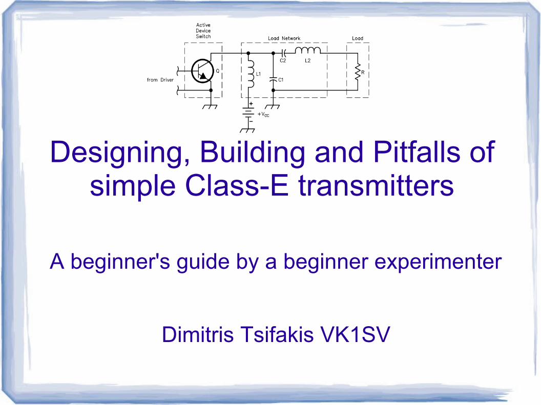
Designing, Building and Pitfalls of simple Class-E transmitters
A beginner's guide by a beginner experimenter
Dimitris Tsifakis VK1SV
Overview
● Introduction to Class-E● Design and implementation of a Class-E
amplifier● Selecting a FET● Other component selection● Good and not so good waveforms● Special topics● Ideas

Introduction to Class-E
● Class A (360°), B(180°) and C(120°)● Class D: Switching amplifier● Class E: Read the Sokal article!
– General concept is high voltage and high current do not exist at the same time across the switching device (FET)
– High efficiency (typically much better than 80%)
– Easy to design, works every time!
– Suitable for single FET transmitters
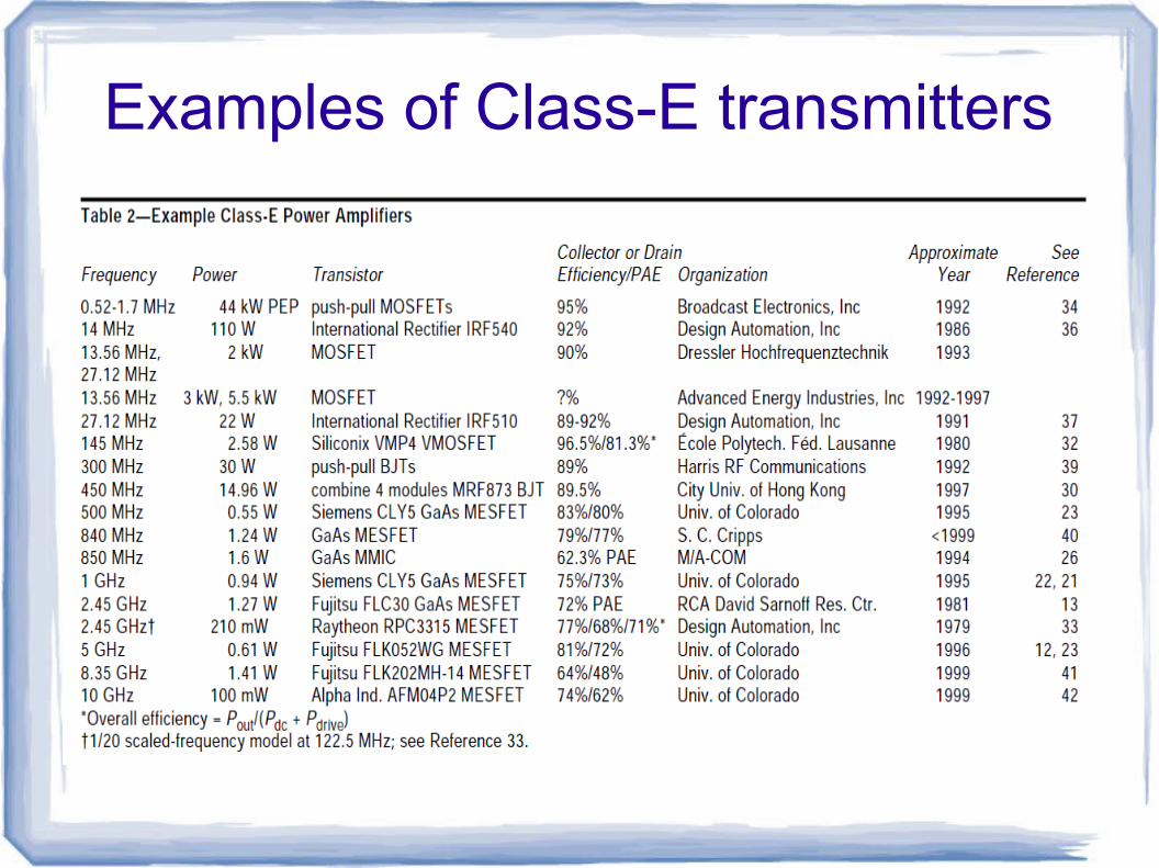
Examples of Class-E transmitters
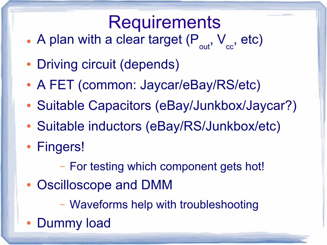
Requirements● A plan with a clear target (P
out, V
cc, etc)
● Driving circuit (depends)● A FET (common: Jaycar/eBay/RS/etc)● Suitable Capacitors (eBay/Junkbox/Jaycar?)● Suitable inductors (eBay/RS/Junkbox/etc)● Fingers!
– For testing which component gets hot!
● Oscilloscope and DMM– Waveforms help with troubleshooting
● Dummy load


Sokal article (the important bits)

Design● Sokal article● VK2ZAY online calculator● Alan Melia G3NYK spreadsheet
– http://www.alan.melia.btinternet.co.uk/classepa.htm
● Driving circuit– Square wave, ~50% duty cycle, drive FET to
saturation (8 or 9 volts, depends on FET)
– MOSFET drivers
– CMOS – TTL -DDS – Signal generator
– The capacitive reactance of Ciss
will determine the
driving requirements

Driving the FET
● Ferrite bead on gate pin or a few ohms in series to avoid parasitic VHF oscillations
● Driving a capacitor (Ciss)● Xc=1/2*pi*f*C● For low C, F drive directly from CMOS IC?● Dedicated MOSFET driver ICs
– TC4420, TC4427, etc
● A FET to drive the FET?
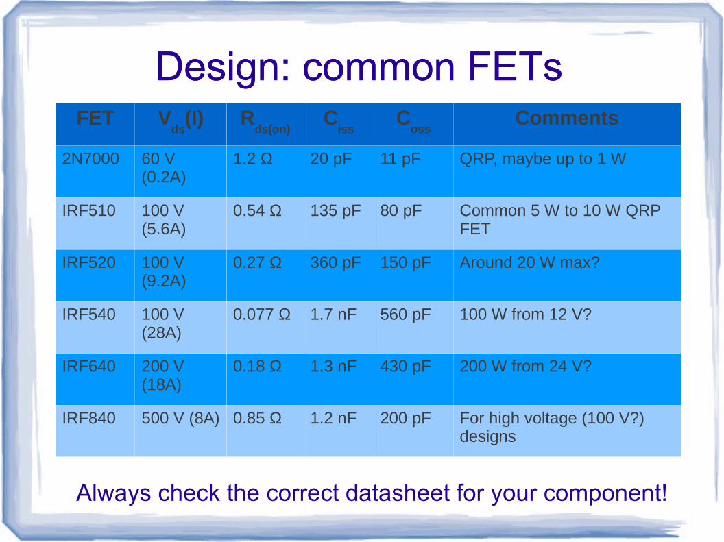
Design: common FETsFET V
ds(I) R
ds(on)C
issC
ossComments
2N7000 60 V (0.2A)
1.2 Ω 20 pF 11 pF QRP, maybe up to 1 W
IRF510 100 V (5.6A)
0.54 Ω 135 pF 80 pF Common 5 W to 10 W QRP FET
IRF520 100 V (9.2A)
0.27 Ω 360 pF 150 pF Around 20 W max?
IRF540 100 V (28A)
0.077 Ω 1.7 nF 560 pF 100 W from 12 V?
IRF640 200 V (18A)
0.18 Ω 1.3 nF 430 pF 200 W from 24 V?
IRF840 500 V (8A) 0.85 Ω 1.2 nF 200 pF For high voltage (100 V?) designs
Design: common FETs
Always check the correct datasheet for your component!
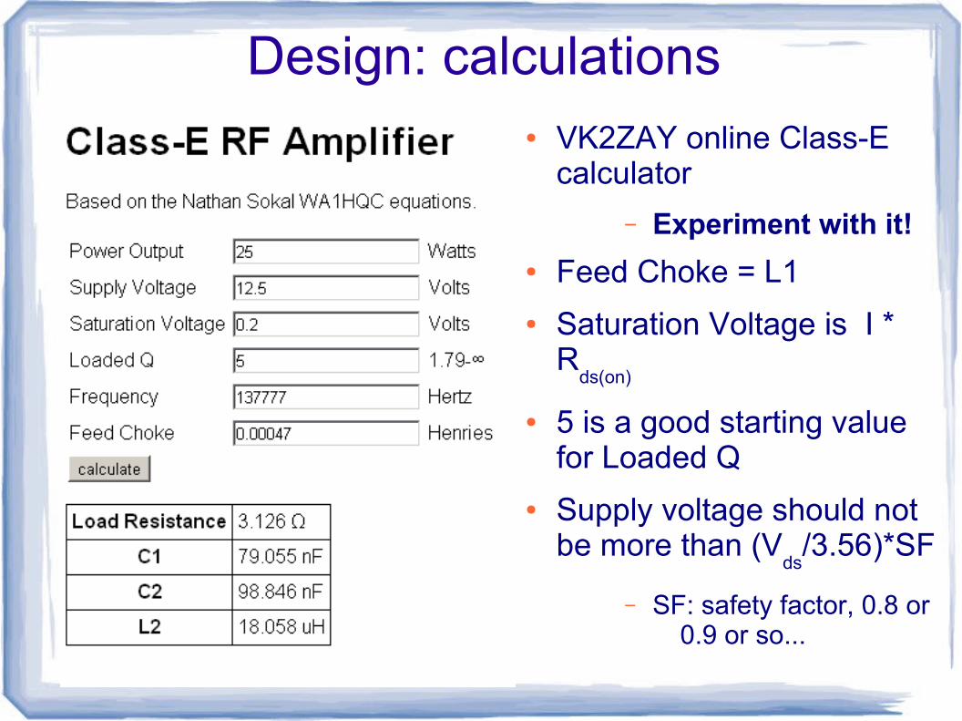
Design: calculations● VK2ZAY online Class-E
calculator
– Experiment with it!
● Feed Choke = L1
● Saturation Voltage is I * R
ds(on)
● 5 is a good starting value for Loaded Q
● Supply voltage should not be more than (V
ds/3.56)*SF
– SF: safety factor, 0.8 or 0.9 or so...

Implementation: L1
● Not critical!● 30x the load impedance● Ferrite toroid
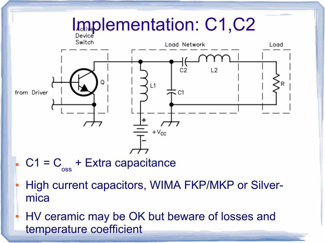
Implementation: C1,C2
● C1 = Coss
+ Extra capacitance
● High current capacitors, WIMA FKP/MKP or Silver-mica
● HV ceramic may be OK but beware of losses and temperature coefficient

Implementation: L2
● Amidon mix 2 for LF to 40m, mix 6 for higher frequencies
● Critical

Implementation: impedance transformer
● Primary: 3x or more the load impedance
– XL=2*pi*f*L
● Secondary according to formula:– N1/N2=SQRT(Z1/Z2)
● Ferrite– High AL RFI ferrites seem to work OK
– Experiment
● Finger test for efficiency!

Waveforms
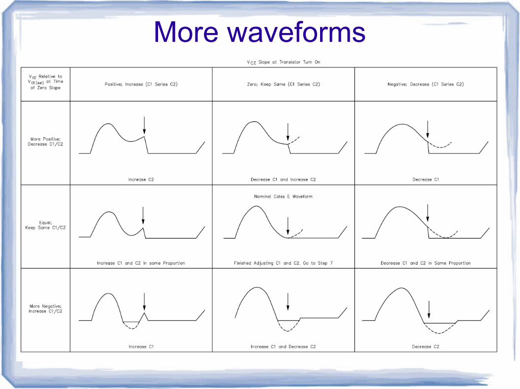
More waveforms
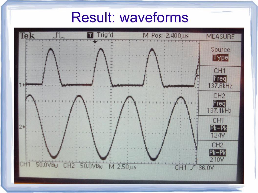
Result: waveforms

Finishing touch, hints and tips
● Harmonics are -20 dBc or better● An LPF is needed (but it's not going to work
very hard!)– WA4DSY web site
– SM caps and -2 or -6 mix
● Heat sink on FET● Toroid calculator
– http://toroid.info/T50-2
Special topics: Amplitude modulation● Easiest option: drain modulation
– Voltage should swing between 0 V and 2x Vcc
for
100% modulation
– Design for 2x Vcc
, ensure FET and other
components are suitable for that power
– Modulation transformer: dare I suggest a big power toroid with appropriate turns ratio?
● Other maybe interesting option: modulation by duty cycle change of the gate driving signal
– Homework for high achieving students!
– (I have not tried this, but I think it's a valid way of doing this)
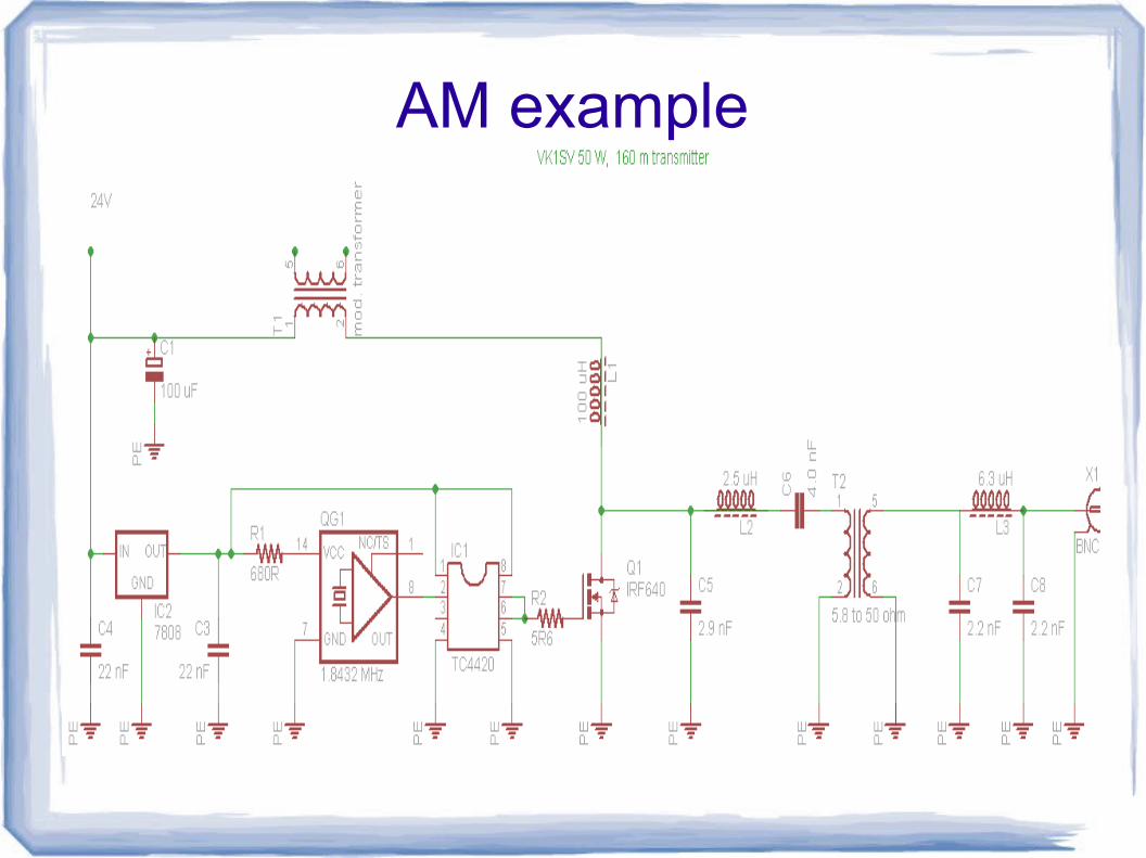
AM example
Ideas● LF/MF transmitter of course!
● 10.140 MHz QRSS beacon (other freqs too!)
● AM transmitter for 160m/80m/40m– 7.125 MHz AM hobebrewer's network every Saturday morning
– Combine with super simple single conversion superhet receiver,based on AM-radio-in-a-chip (a topic for a future presentation?)
● High power CW transmitter that fits in your pocket– Watch those key clicks!
● QRP CW transmitter for field/fun use!– Xtal oscillator
● Dedicated WSPR beacon (combine with DDS)
● Opera beacon (like WSPR only single freq – CW TX)
Questions?


![[PSS 2A-1Z9 E] Pressure Transmitters Options and Accessories · 2016-01-14 · Product Specifications PSS 2A-1Z9 E I/A Series® Electronic Pressure Transmitters Options and Accessories](https://cdn.vdocument.in/doc/165x107/5f622fe7c4491f1a270fecee/pss-2a-1z9-e-pressure-transmitters-options-and-accessories-2016-01-14-product.jpg)


