Designing OSPF
Networks
284_045/c2 1
284_045/c23
Agenda
• Technical Overview
• Protocol Functionality
• Design Considerations
• Case Studies
284_045/c24
OSPF Technical Overview
• Background
• Features
• Hierarchical Organization
284_045/c25
Why OSPF: Advantages
• Fast re-routing
• Minimizes routing protocol traffic
• Multi-vendor

284_045/c26
Why OSPF: Disadvantages
• Topology restrictive
• Not easily centrally controlled
Security transmitted in clear
No route filtering

284_045/c27
Link State Technology
Topology information iskept in a database separatefrom the routing table
Q’s Link State
X’s Link State
Z’s Link States
Y
ABC
QZX
21313
284_045/c28
OSPF Background
• Dynamic routing protocol
• Link state or SPF technology
• Developed by OSPF Working Group of IETF
• Intra-autonomous system (IGP)
• Designed expressly for TCP/IP Internet environment

284_045/c29
OSPF Background (Cont.)
• Runs directly over IP (Protocol 89)
• Each router maintains an identical database (within areas)
• Each router constructs a tree of shortest paths by running SPF algorithm on the database
• Tree provides route to each known destination
• Cisco’s implementation is fully compliant with the specification as of software release 9.1 (November, 1992)
284_045/c210
OSPF Technical Overview
• Background
• Features
• Hierarchical Organization
284_045/c211
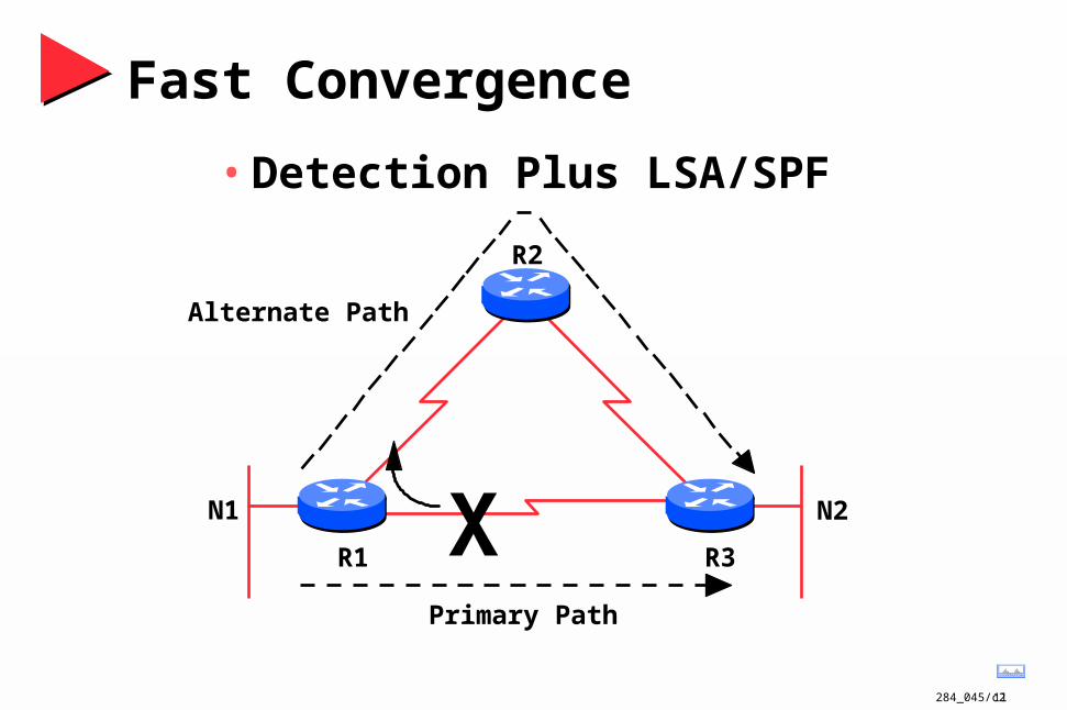
Fast Convergence
• Detection Plus LSA/SPF
XR1 R3
R2
Alternate Path
Primary Path
N1 N2
284_045/c212
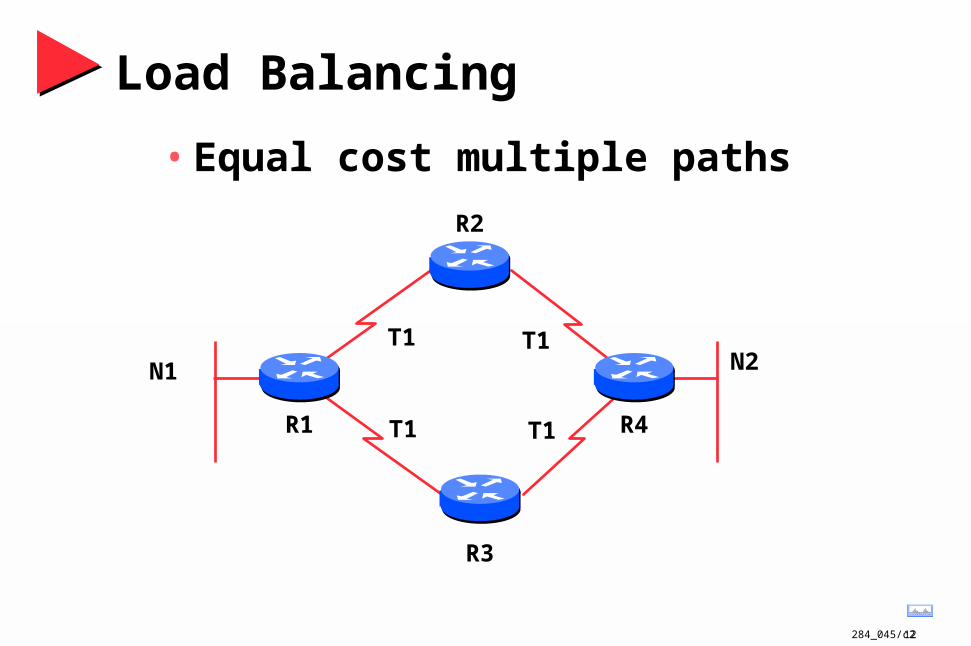
Load Balancing
• Equal cost multiple paths
R1 R4
N2N1
R3
R2
T1 T1
T1 T1
284_045/c213
FDDIDual Ring
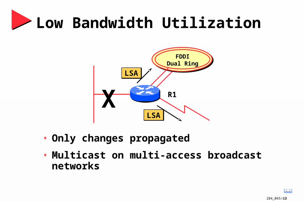
Low Bandwidth Utilization
• Only changes propagated
• Multicast on multi-access broadcast networks
R1
LSAX
LSA
284_045/c214
FDDIDual Ring
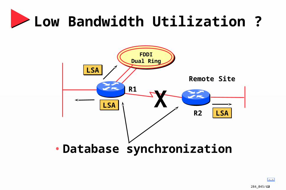
Low Bandwidth Utilization ?
• Database synchronization
R1
LSA X
LSARemote Site
R2 LSA
284_045/c215
FDDI Dual Ring
FDDI Dual Ring
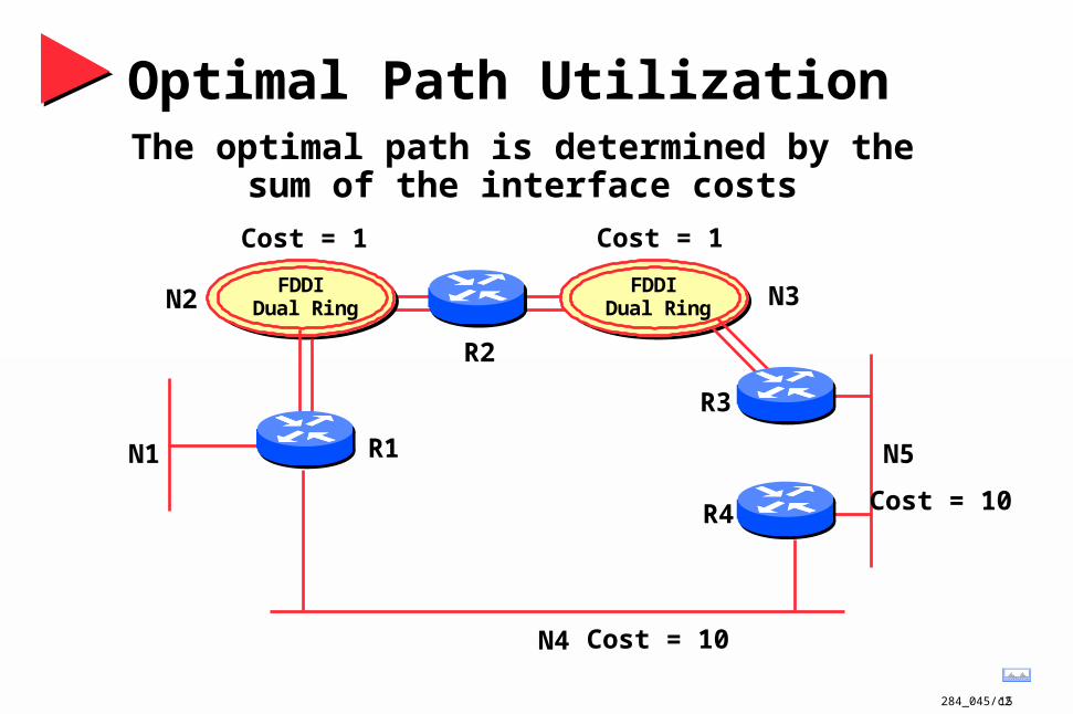
Optimal Path Utilization
N1
N2 N3
N4
N5R1
R2
R3
R4
Cost = 1 Cost = 1
Cost = 10
Cost = 10
The optimal path is determined by thesum of the interface costs
284_045/c216
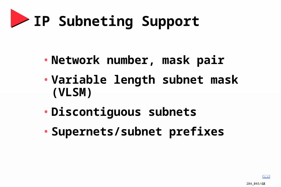
IP Subneting Support
• Network number, mask pair
• Variable length subnet mask (VLSM)
• Discontiguous subnets
• Supernets/subnet prefixes
284_045/c217
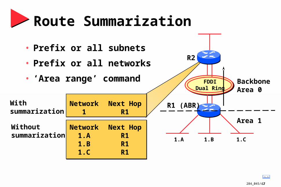
Route Summarization
• Prefix or all subnets
• Prefix or all networks
• ‘Area range’ command
1.A 1.B 1.C
FDDIDual Ring
R1 (ABR)
R2
Network1
Next HopR1
Network1.A1.B1.C
Next HopR1R1R1
With summarization
Withoutsummarization
BackboneArea 0
Area 1
284_045/c218
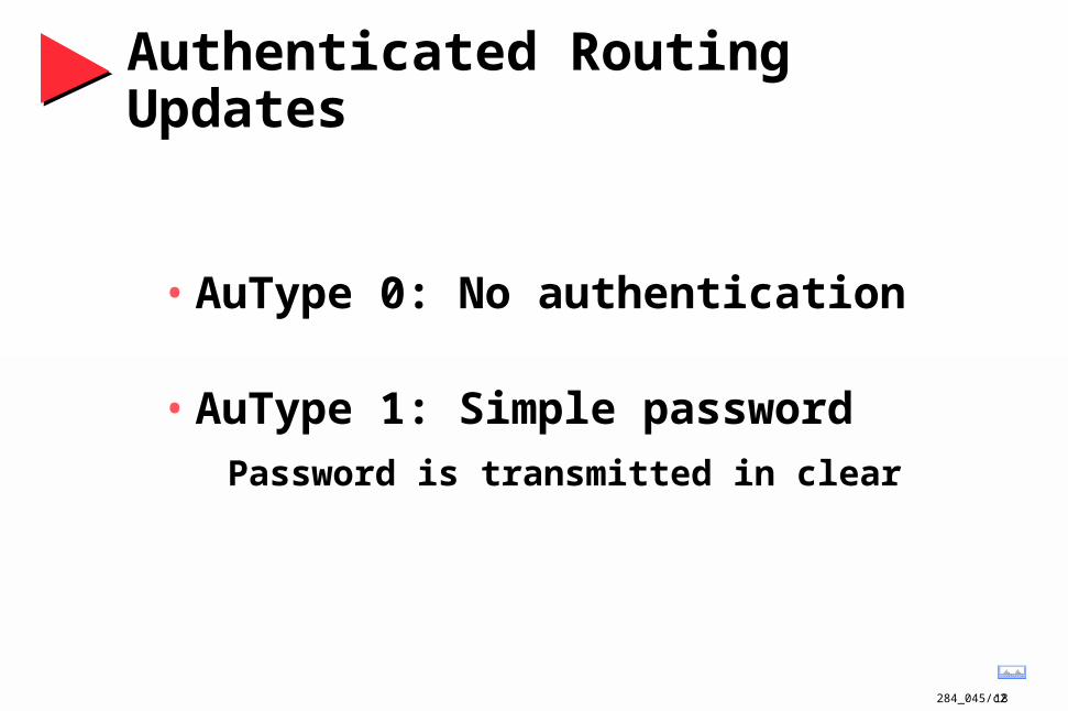
Authenticated Routing Updates
• AuType 0: No authentication
• AuType 1: Simple password
Password is transmitted in clear
284_045/c219
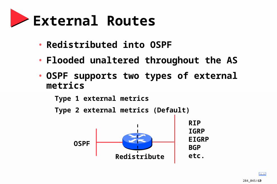
External Routes
• Redistributed into OSPF
• Flooded unaltered throughout the AS
• OSPF supports two types of external metricsType 1 external metrics
Type 2 external metrics (Default)
RIPIGRPEIGRPBGPetc.
OSPF
Redistribute

284_045/c220
External Routes
• Type 1 external metric
NetworkN1N1
Type 11110
Next HopR1R2
Cost = 10
to N1External Cost = 1
to N1External Cost = 2R2
R3
R1
Cost = 8
Selected Route
284_045/c221
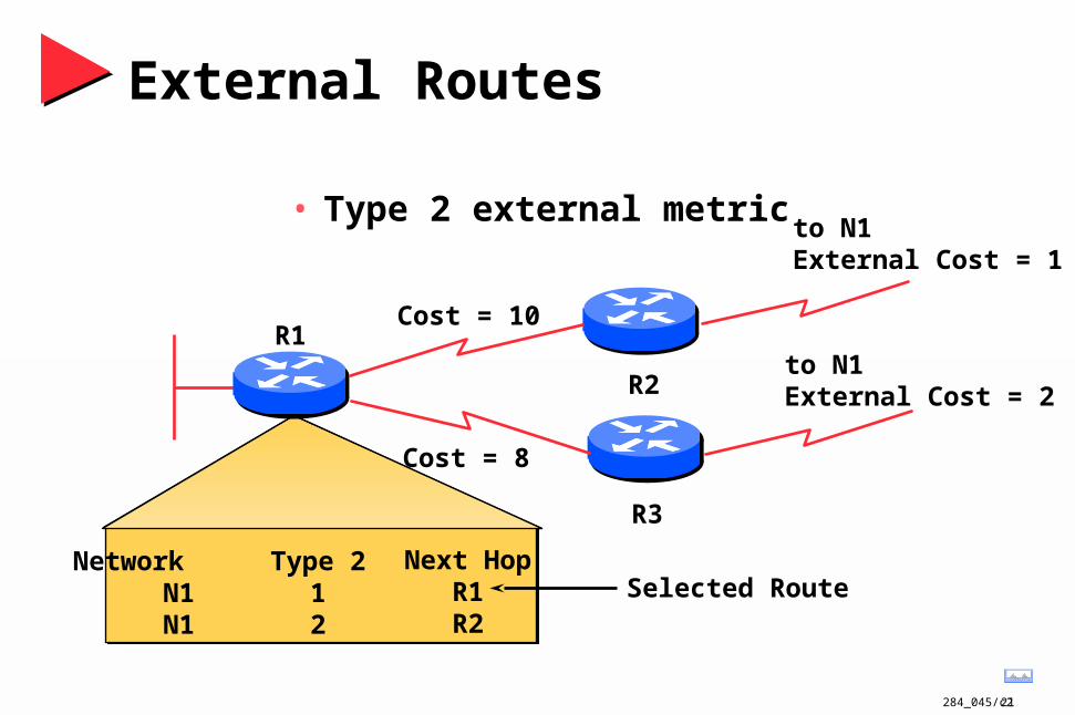
External Routes
• Type 2 external metric
NetworkN1N1
Type 212
Next HopR1R2
Cost = 10
to N1External Cost = 1
to N1External Cost = 2R2
R3
R1
Cost = 8
Selected Route

284_045/c222
External Routes• Forwarding Address on shared/common network
(Field in AS external links advertisement)
AS#2R1
R2
R3
AS#1
FDDIDualRing
N1
N2N3OSPF
BGP
TokenRing
NetworkN3
Next HopR3

284_045/c223
Route Tagging
A
BC
D• Autonomous System B wants toPropagate routes from A —> D,
but NOT propagate routes from C —> D• OSPF tags routes with AS input
This info can be used when redistributing routes

284_045/c224
TOS Based Routing
• IP header supports 3 bit priority field
• IP header supports 4 special types of serviceBandwidth
Delay
MTU
Cost
• Currently only TOS 0 supported

284_045/c225
Utilizes IP Multicast for Sending/Receiving Updates
• Broadcast networksDR and BDR —> AllSPFRouters (224.0.0.5)
All other routers —> AllDRRouters (224.0.0.6)
• Hello packets sent to AllSPFRouters (Unicast on point-to-point and virtual links)
284_045/c226
OSPF Technical Overview
• Background
• Features
• Hierarchical Organization

284_045/c227
BackboneArea #0
Area #1 Area #2 Area #3
Hierarchical Structure
• Structure must exist or be created• Explicit topology has precedence over addressing

284_045/c228
OSPF Areas
• OSPF areasGroup of contiguous hosts and networks
Per area topological database
Backbone area (contiguous)
Virtual links
Inter-area routing Area 1Area 4
Area 0
Area 2 Area 3

284_045/c229
OSPF Areas
• RulesBackbone area must be present
All other areas must have connection to backbone
Backbone must be contiguous
BackboneArea #0
Area #1 Area #2 Area #3
284_045/c230
BackboneArea #0
Area #1 Area #2 Area #3
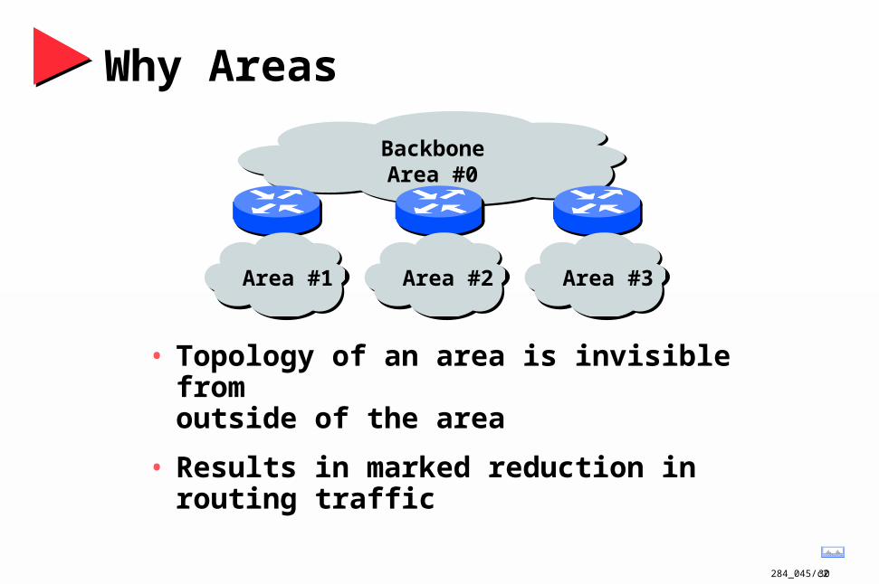
Why Areas
• Topology of an area is invisible from outside of the area
• Results in marked reduction in routing traffic

284_045/c231
Topology/Link State Database
• A router has a separate LS database for each area to which it belongs
• All routers belonging to the same area have identical database
• SPF calculation is performed separately for each area
• LSA flooding is bounded by area

284_045/c232
Area Link State Database
• Area database is composed of:
Router links advertisements
Network links advertisements
Summary links advertisements (IP network, ASBR)
AS external advertisements (in non-stub areas)

284_045/c233
Area 1
Area 0
Area 2 Area 3
Classification of Routers
IR
ABR/BR
IR/BR
To other AS
ASBR • Internal Router (IR)
• Area Border Router (ABR)
• Backbone Router (BR)
• Autonomous System Border Router (ASBR)
284_045/c234
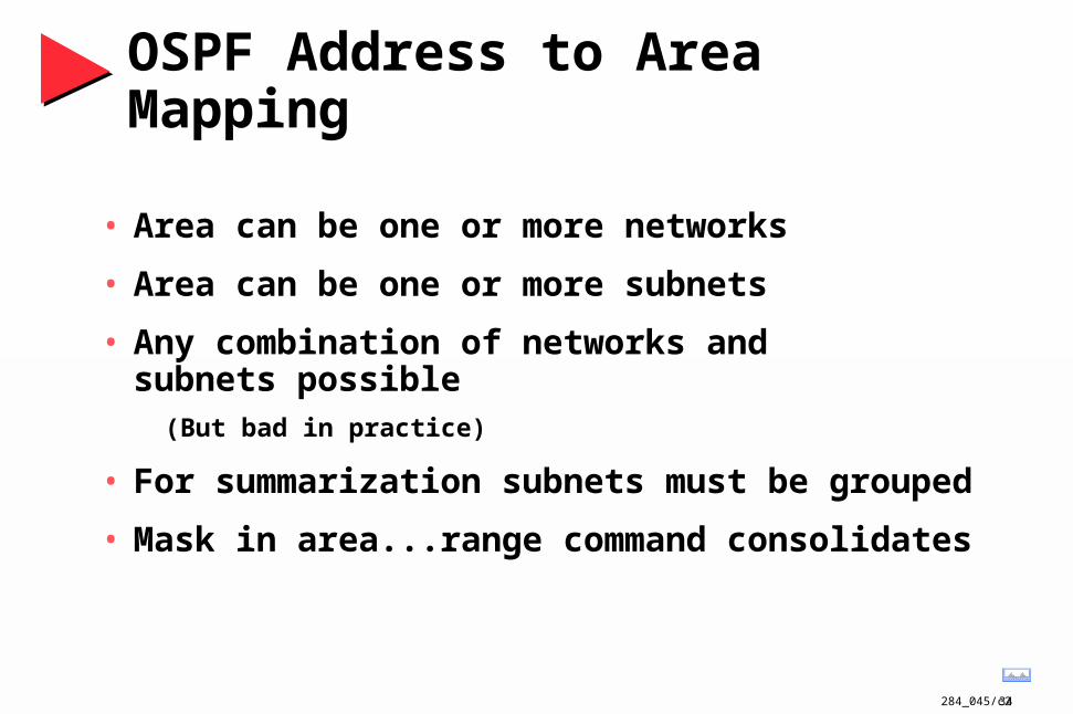
OSPF Address to Area Mapping
• Area can be one or more networks
• Area can be one or more subnets
• Any combination of networks and subnets possible
(But bad in practice)
• For summarization subnets must be grouped
• Mask in area...range command consolidates

284_045/c235
Virtual Links
BackboneBackboneArea 0Area 0
BackboneBackboneArea 0Area 0
Area 3
Area 1
Area 2
• Virtual links configured between any two backbone routers that have an interface to a common non-backbone area
• A router connected to two or more areas is considered to be a backbone router

284_045/c236
Agenda
• Technical Overview
• Protocol Functionality
• Design Considerations
• Case Studies

284_045/c237
Protocol Functionality
• Bringing up adjacencies
• Convergence
• Subneting
• Route summarization
• Area classification
284_045/c238
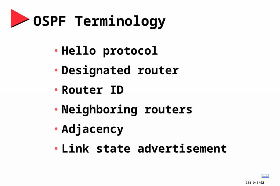
OSPF Terminology
• Hello protocol
• Designated router
• Router ID
• Neighboring routers
• Adjacency
• Link state advertisement
284_045/c239
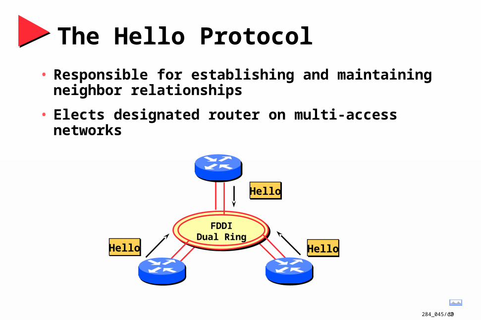
The Hello Protocol
• Responsible for establishing and maintaining neighbor relationships
• Elects designated router on multi-access networks
FDDIDual Ring
Hello
HelloHello

284_045/c240
The Hello Packet
• Router priority
• Hello interval
• Router dead interval
• Network mask
• Options: T-bit, E-bit
• List of neighbors
FDDIDual Ring
Hello
HelloHello
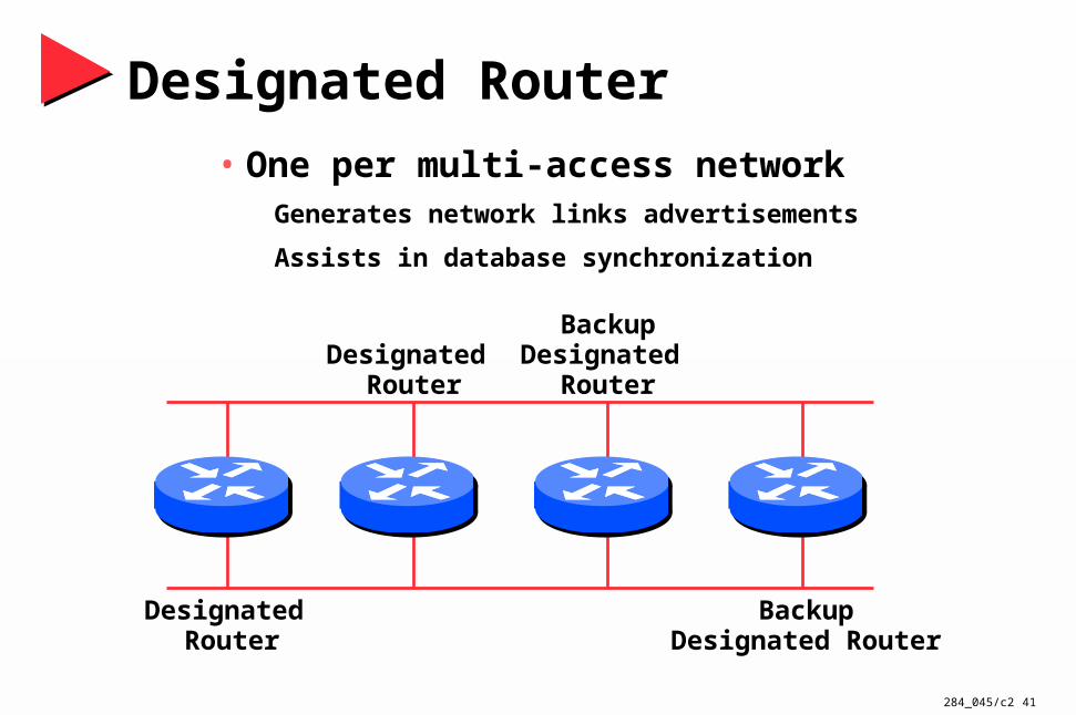
Designated Router
• One per multi-access networkGenerates network links advertisements
Assists in database synchronization
Designated Router
Designated Router
BackupDesignated Router
BackupDesignated
Router
284_045/c2 41

284_045/c242
Designated Router by Priority
• Configured priority (per interface)
• Else determined by highest router ID
Router ID is the highest IP address on the box
144.254.3.5
R2 Router ID = 131.108.3.3
131.108.3.2 131.108.3.3
R1 Router ID = 144.254.3.5
DR
284_045/c243
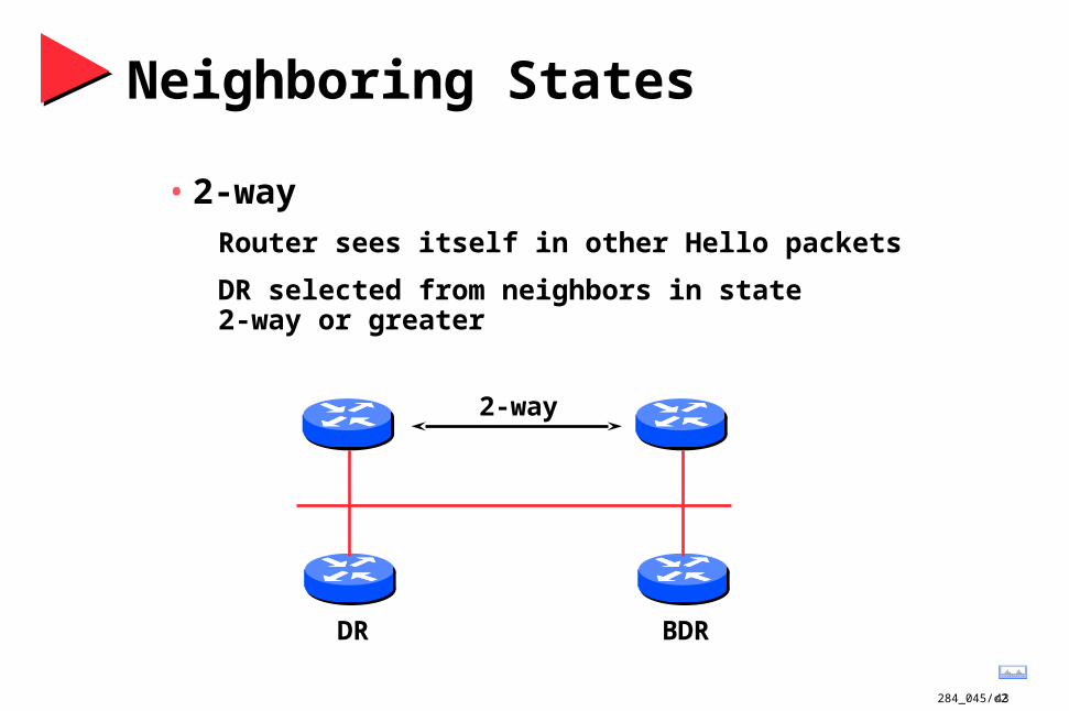
Neighboring States
• 2-way
Router sees itself in other Hello packets
DR selected from neighbors in state 2-way or greater
DR BDR
2-way
284_045/c244
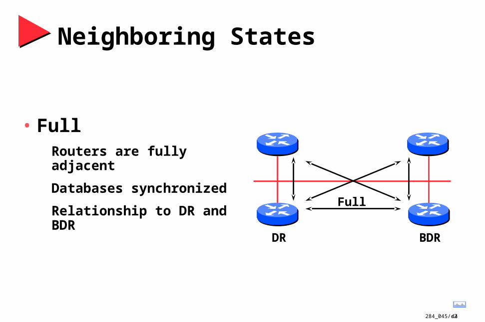
Neighboring States
• FullRouters are fully adjacent
Databases synchronized
Relationship to DR and BDR
DR BDR
Full

284_045/c245
When to Become Adjacent
• Underlying network is point to point
• Underlying network type is virtual link
• The router itself is the designated router
• The router itself is the backup designated router
• The neighboring router is the designated router
• The neighboring router is the backup designated router
284_045/c246
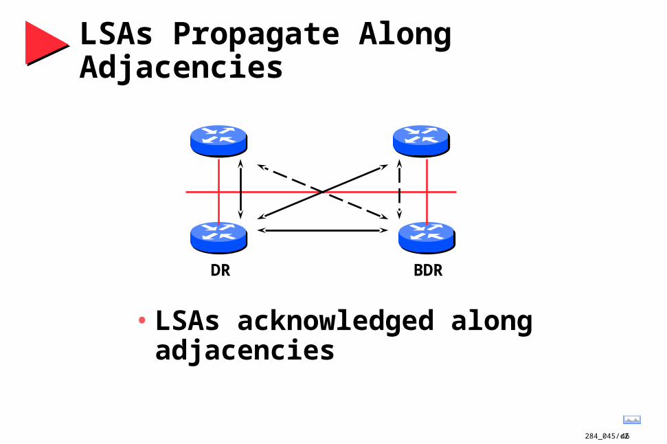
LSAs Propagate Along Adjacencies
• LSAs acknowledged along adjacencies
DR BDR
284_045/c247
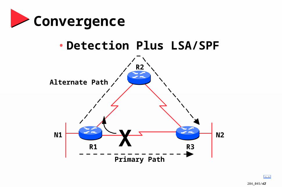
Convergence
• Detection Plus LSA/SPF
XR1 R3
R2
N2
Alternate Path
Primary Path
N1

284_045/c248
Convergence
• Fault detectionSerial lines
Detection immediate for carrier loss
2 to 3 times keepalive otherwisekeepalive 10 seconds by default
Token Ring and FDDI immediate
Ethernet
2 to 3 times keepalive
Hello can supersede keepalive
Dead timer is 40 sec by default
XR1
N1
Primary Path
Alternate Path

284_045/c249
Convergence
• Finding a new route
LSA flooded throughout area
Acknowledgment based
Topology database synchronized
Each router derives routing table
Tree to each destination network
LSA
XR1
N1

284_045/c250
Convergence
• Finding a new routeLoad balancing provides immediate convergence
Equal cost paths only
R1
R4
N2N1
R3
R2
T1 T1
T1 T1
284_045/c251
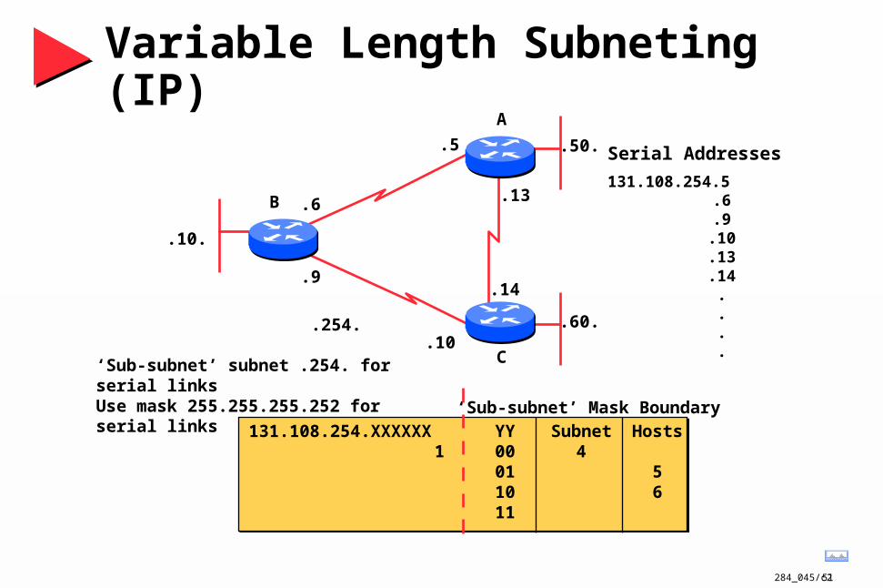
Variable Length Subneting (IP)
.10.
.6
.50.
.13
.60..254.
‘Sub-subnet’ subnet .254. for serial linksUse mask 255.255.255.252 for serial links
‘Sub-subnet’ Mask Boundary
131.108.254.XXXXXX YY Subnet Hosts1 00 4
01 510 611
.9
.10
.14
.5 Serial Addresses
131.108.254.5.6.9
.10
.13
.14....
A
C
B
284_045/c252
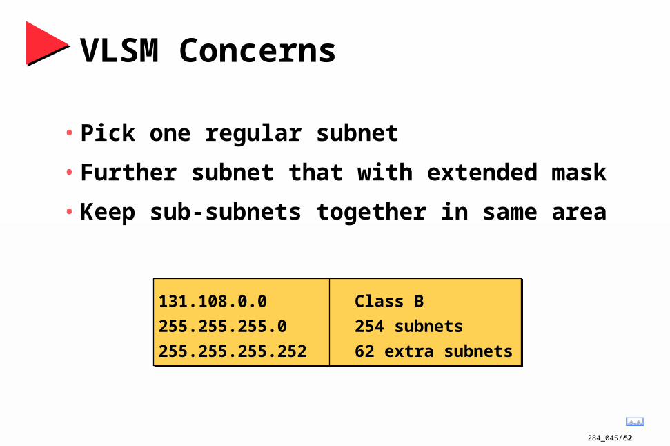
VLSM Concerns
• Pick one regular subnet
• Further subnet that with extended mask
• Keep sub-subnets together in same area
131.108.0.0
255.255.255.0
255.255.255.252
Class B
254 subnets
62 extra subnets

284_045/c253
Discontiguous Subnets
Area 1network 131.108.0.0subnets 17-31range 255.255.240.0
Area 2network 131.108.0.0subnets 33-47range 255.255.240.0
Area 3network 131.108.0.0subnets 49-63range 255.255.240.0
Area 0network 192.117.49.0range 255.255.255.0
284_045/c254
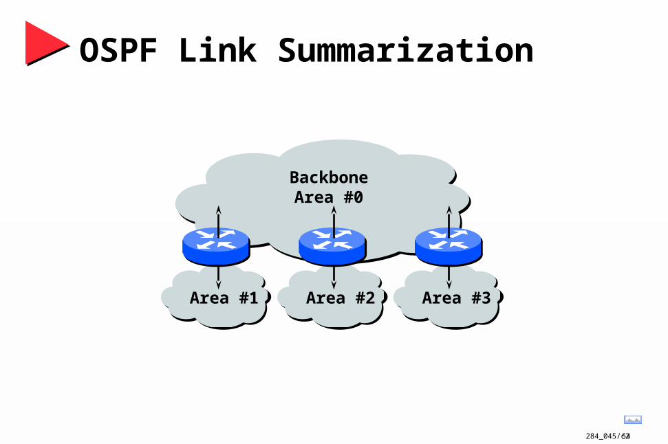
BackboneArea #0
Area #1 Area #2 Area #3
OSPF Link Summarization

284_045/c255
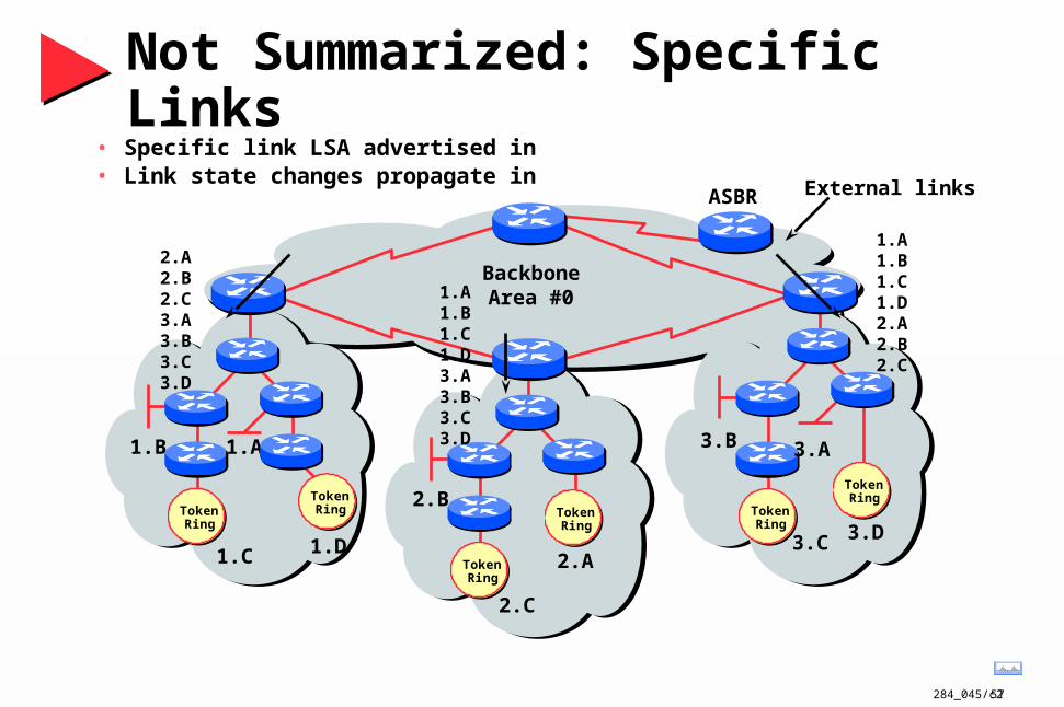
Not Summarized: Specific Links
BackboneArea #0
External links
1.A
1.C
1.B
1.D
TokenRing
TokenRing Token
Ring
TokenRing
3.D
3.A
3.C
3.B
1.A1.B1.C1.D
3.A3.B3.C3.D
2.A2.B2.C
2.A
2.C
2.B
TokenRing
TokenRing
• Specific link LSA advertised out• Link state changes propagate out
ASBR

284_045/c256
Summarized: Summary Links
BackboneArea #0
ASBR
External links
1.A
1.C
1.B
1.D
TokenRing
TokenRing
TokenRing
TokenRing
3.D
3.A
3.C
3.B
2.A
2.B
TokenRing
TokenRing
• Only summary LSA advertised out• Link state changes do not propagate
1 3
2
284_045/c257
BackboneArea #0
External links
1.A
1.C
1.B
1.D
TokenRing
TokenRing Token
Ring
TokenRing
3.D
3.A
3.C
3.B
2.A
2.C
2.B
TokenRing
TokenRing
ASBR
Not Summarized: Specific Links
2.A2.B2.C3.A3.B3.C3.D
1.A1.B1.C1.D3.A3.B3.C3.D
1.A1.B1.C1.D2.A2.B2.C
• Specific link LSA advertised in• Link state changes propagate in

284_045/c258
Summarized: Summary Links
BackboneArea #0
ASBR
External links
1.A
1.C
1.B
1.D
TokenRing
TokenRing
TokenRing
TokenRing
3.D
3.A
3.C
3.B
2.A
2.B
TokenRing
TokenRing
2,3
1,3
• Only summary LSA advertised out• Link state changes do not propagate
1,2
284_045/c259
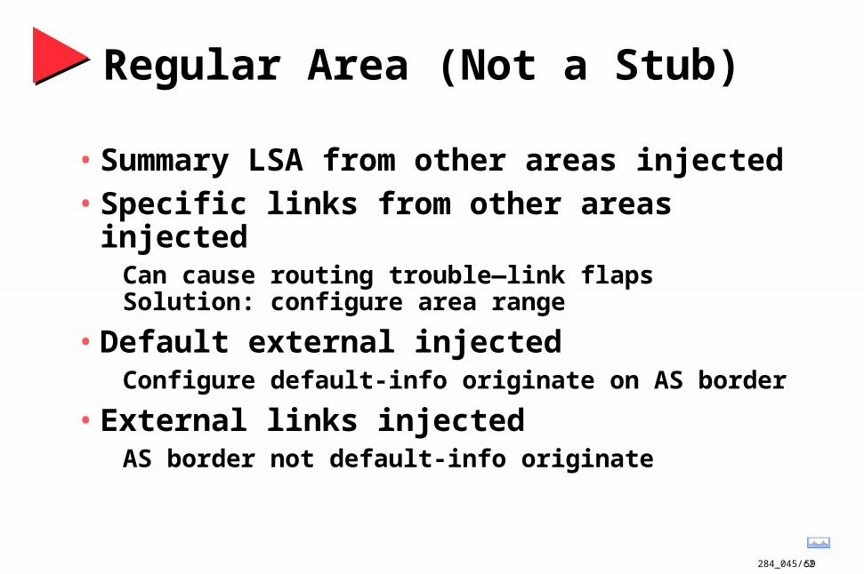
Regular Area (Not a Stub)
• Summary LSA from other areas injected• Specific links from other areas injected
Can cause routing trouble—link flaps Solution: configure area range
• Default external injectedConfigure default-info originate on AS border
• External links injectedAS border not default-info originate
284_045/c260
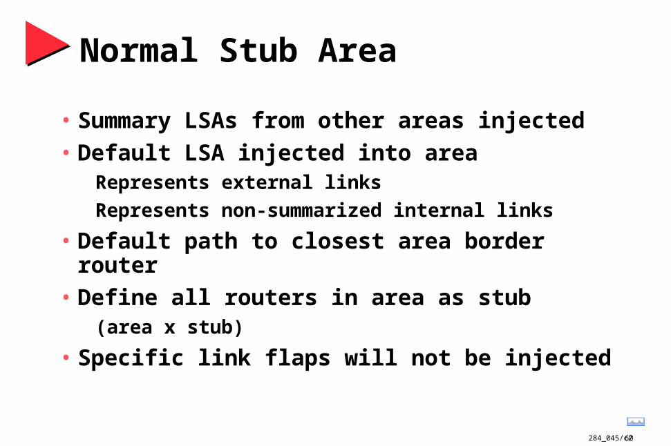
Normal Stub Area
• Summary LSAs from other areas injected
• Default LSA injected into areaRepresents external links
Represents non-summarized internal links
• Default path to closest area border router
• Define all routers in area as stub (area x stub)
• Specific link flaps will not be injected

284_045/c261
Totally Stubby Area
• Configure ‘area x stub no-summary’
• Default LSA injected into areaRepresents all external links
Represents all summarized internal links
Represents non-sumarized internal links
• Default path to closest area border router
• Define all routers totally stubby
• Specific link flaps will not be injected
284_045/c262
Agenda
• Technical Overview
• Protocol Functionality
• Design Considerations
• Case Studies

284_045/c263
Design Considerations
• Network hierarchy
• Addressing

284_045/c264
Hierarchical Network Structure
Distribution
Core
Access
Optimal TransportBetween Sites
Policy Based Connectivity
Local/Remote Workgroup Access

284_045/c265
Hierarchical Network Structure
S S
SS
Distribution
Access
FDDI Dual Ring
FDDI Dual Ring
FDDI Dual Ring
FDDI Dual Ring
Core
284_045/c266
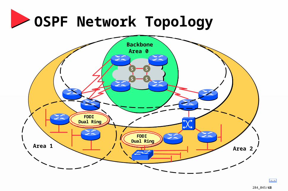
OSPF Network Topology
S S
SS
BackboneArea 0
Area 1
FDDI Dual Ring
FDDI Dual Ring
Area 2
FDDI Dual Ring
FDDI Dual Ring
284_045/c267
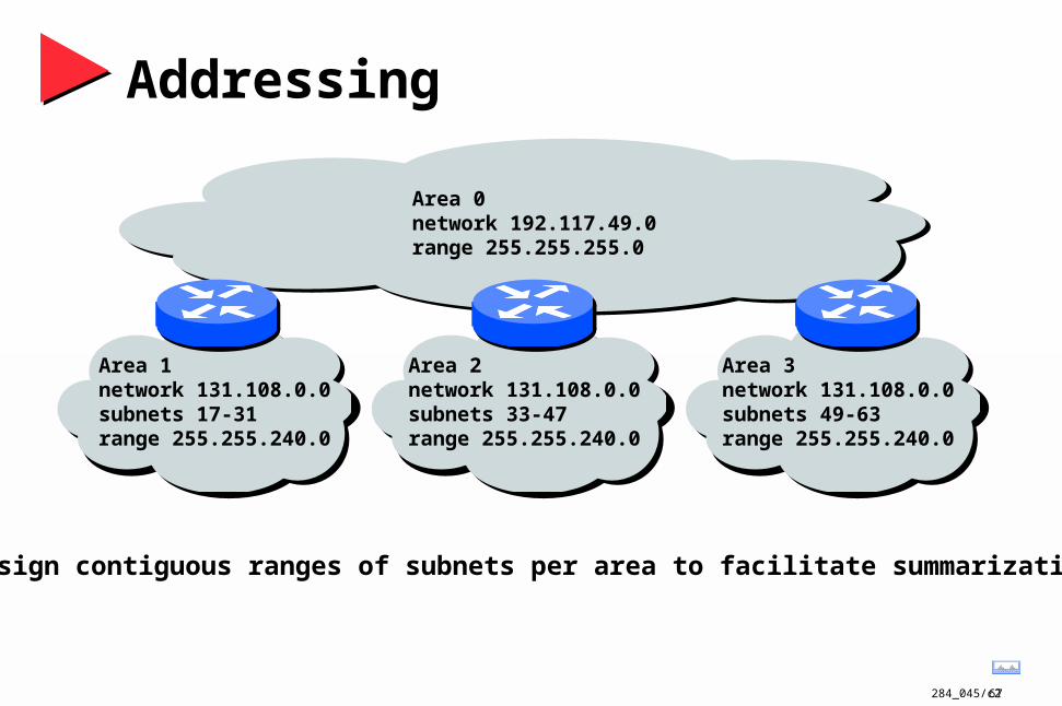
Addressing
Area 1network 131.108.0.0subnets 17-31range 255.255.240.0
Area 2network 131.108.0.0subnets 33-47range 255.255.240.0
Area 3network 131.108.0.0subnets 49-63range 255.255.240.0
Area 0network 192.117.49.0range 255.255.255.0
Assign contiguous ranges of subnets per area to facilitate summarization
284_045/c268
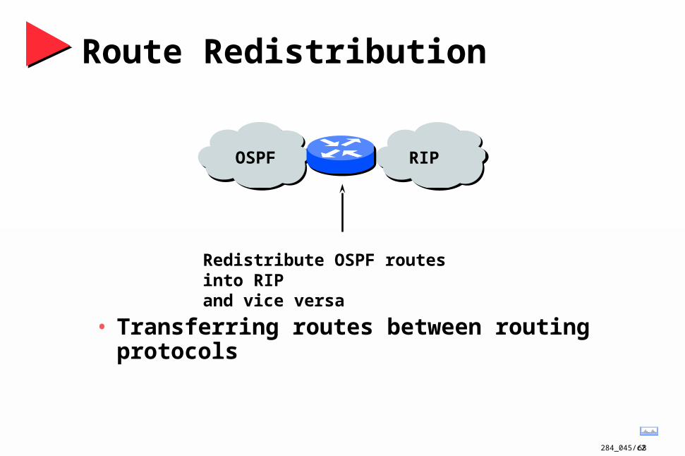
OSPF RIP
Route Redistribution
• Transferring routes between routing protocols
Redistribute OSPF routes into RIPand vice versa
284_045/c269
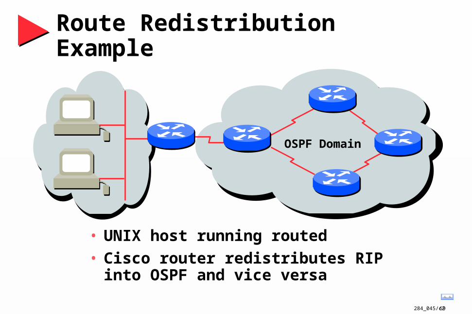
Route Redistribution Example
• UNIX host running routed
• Cisco router redistributes RIP into OSPF and vice versa
OSPF Domain

284_045/c270
Good OSPF Backbone Design
• Avoid large mesh backbones
• Best—collapsed LAN backbone
FDDI Dual Ring
FDDI Dual Ring

284_045/c271
Scalable OSPF Network Design
• Area hierarchy
• Stub areas
• Addressing
• Route summarization

284_045/c272
Agenda
• Technical Overview
• Protocol Functionality
• Design Considerations
• Case Studies
284_045/c273
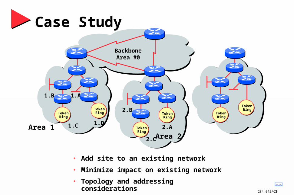
Case Study
• Add site to an existing network
• Minimize impact on existing network
• Topology and addressing considerations
BackboneArea #0
1.A
1.C
1.B
1.D
TokenRing
TokenRing Token
Ring
TokenRing
2.A
2.C
2.B
TokenRing
TokenRing
Area 1Area 2
284_045/c274
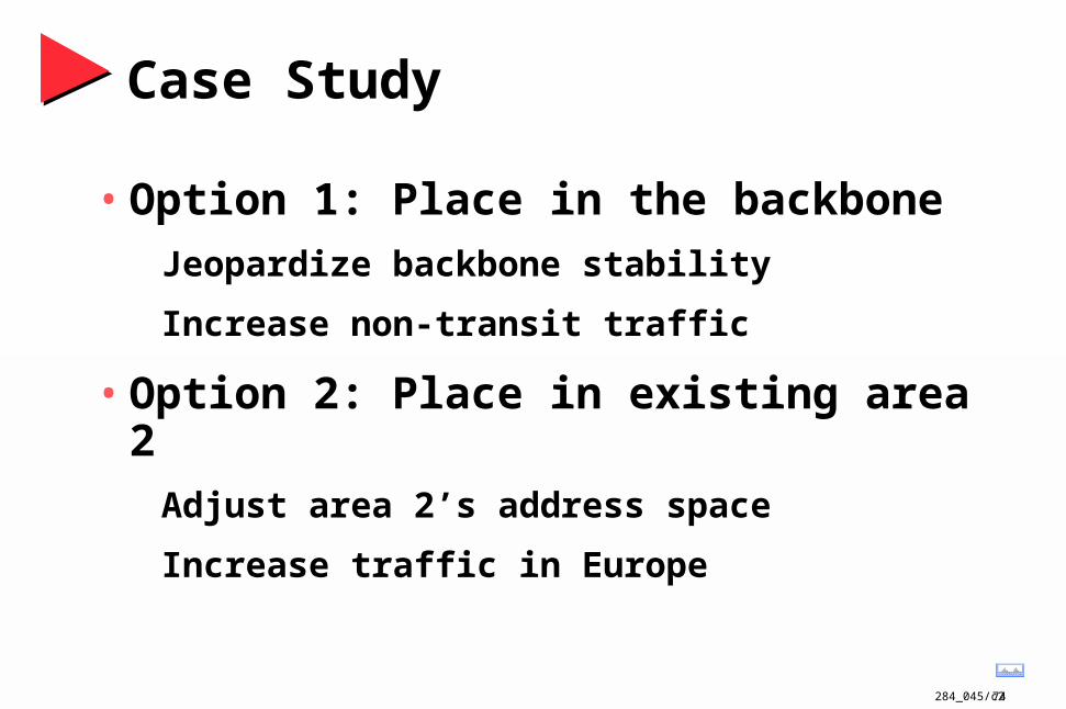
Case Study
• Option 1: Place in the backbone
Jeopardize backbone stability
Increase non-transit traffic
• Option 2: Place in existing area 2
Adjust area 2’s address space
Increase traffic in Europe

284_045/c275
Case Study
• Option 3: Create new area
Requires unique address space
Logically easy
Optimizes routing

284_045/c276
Case Study
• Option 3: Create new area
Requires unique address space
Logically easy, optimizes routing
BackboneArea #0
1.A
1.C
1.B
1.D
TokenRing
TokenRing Token
Ring
TokenRing
2.A
2.C
2.B
TokenRing
TokenRing
Area 1Area 2 Area 3
284_045/c277
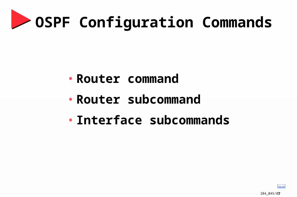
OSPF Configuration Commands
• Router command
• Router subcommand
• Interface subcommands

284_045/c278
Router Command
• router ospf {as}
Multiple OSPF processes can be configured
Autonomous system must be on unique interfaces
as# not transmitted
284_045/c279
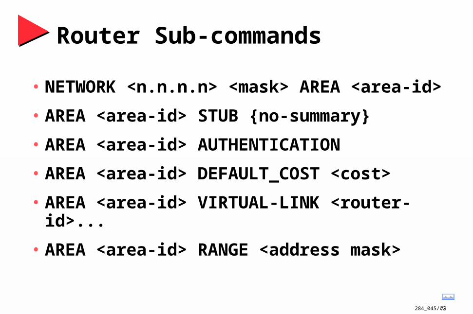
Router Sub-commands
• NETWORK <n.n.n.n> <mask> AREA <area-id>
• AREA <area-id> STUB {no-summary}
• AREA <area-id> AUTHENTICATION
• AREA <area-id> DEFAULT_COST <cost>
• AREA <area-id> VIRTUAL-LINK <router-id>...
• AREA <area-id> RANGE <address mask>
284_045/c280
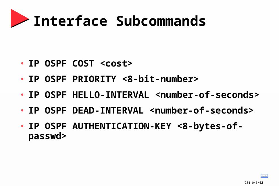
Interface Subcommands
• IP OSPF COST <cost>
• IP OSPF PRIORITY <8-bit-number>
• IP OSPF HELLO-INTERVAL <number-of-seconds>
• IP OSPF DEAD-INTERVAL <number-of-seconds>
• IP OSPF AUTHENTICATION-KEY <8-bytes-of-passwd>

284_045/c281
Redistributing Routes into OSPF
ROUTER OSPF <as#x>
REDISTRIBUTE {protocol} <as#y>
<metric>
<metric-type (1 ro 2)
<tag>
<subnets>
<default>
284_045/c282
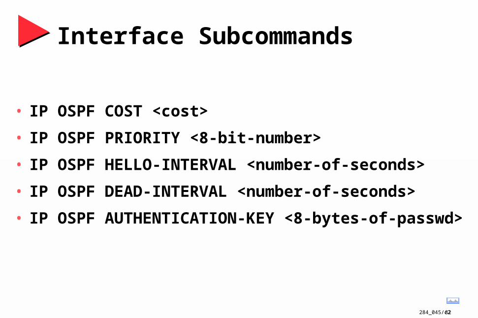
Interface Subcommands
• IP OSPF COST <cost>
• IP OSPF PRIORITY <8-bit-number>
• IP OSPF HELLO-INTERVAL <number-of-seconds>
• IP OSPF DEAD-INTERVAL <number-of-seconds>
• IP OSPF AUTHENTICATION-KEY <8-bytes-of-passwd>
284_045/c283
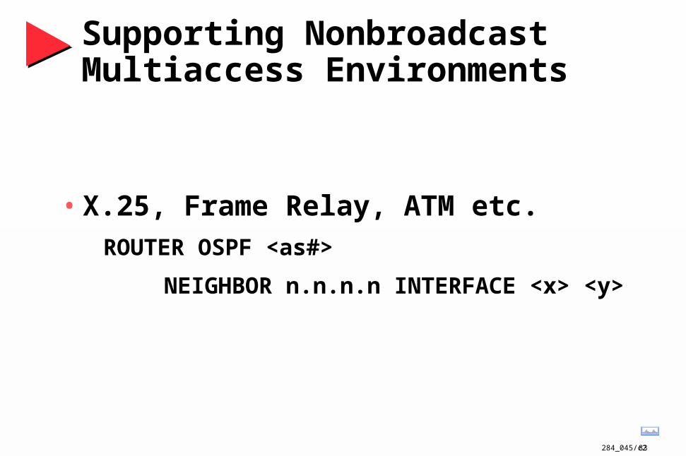
Supporting Nonbroadcast Multiaccess Environments
• X.25, Frame Relay, ATM etc.
ROUTER OSPF <as#>
NEIGHBOR n.n.n.n INTERFACE <x> <y>


