
Cathedral Square Police Kiosk
BU 1217-001 EQ2
Detailed Engineering Evaluation
Quantitative Assessment Report
Christchurch City Council
Cathedral Square Police Kiosk
Detailed Engineering Evaluation
Quantitative Assessment Report Cathedral Square, Christchurch
Christchurch City Council
Opus International Consultants Limited Christchurch Office 20 Moorhouse Avenue PO Box 1482, Christchurch Mail Centre, Christchurch 8140, New Zealand
Telephone: +64 3 363 5400 Facsimile: +64 3 365 7858
Date: October 2012 Reference: 6-QUCCC.43 Status: Final
© Opus International Consultants Limited 2011
Cathedral Square Police Kiosk
Cathedral Square
6-QUCCC.43
October 2012 i
Contents
Executive Summary ...................................................................................................................... ii
1 Introduction .......................................................................................................................... 1
2 Compliance .......................................................................................................................... 1
3 Earthquake Resistance Standards ..................................................................................... 4
4 Background Information ..................................................................................................... 6
5 Structural Damage ............................................................................................................... 8
6 General Observations .......................................................................................................... 8
7 Detailed Seismic Assessment............................................................................................. 8
8 Summary of Geotechnical Appraisal ................................................................................ 11
9 Remedial Options .............................................................................................................. 12
10 Conclusions ....................................................................................................................... 12
11 Recommendations ............................................................................................................. 12
12 Limitations.......................................................................................................................... 12
13 References ......................................................................................................................... 13
Appendix 1 – Photographs
Appendix 2 – Geotechnical Appraisal
Appendix 3 – CERA DEE Spreadsheet

Cathedral Square Police Kiosk
Cathedral Square
6-QUCCC.43
October 2012 ii
Executive Summary
Christchurch City Council appointed Opus International Consultants to carry out a detailed seismic
assessment of the police kiosk in the northern half of Cathedral Square, Christchurch. The key
outcome of this assessment was to ascertain the anticipated seismic performance of the structure
and to compare this performance with current design standards.
Findings of the assessment are:
1. The seismic performance of the police kiosk exceeds 100%NBS. The building is therefore
considered to be of low risk in accordance with the NZSEE 2006 Guidelines for
Assessment and Improvement of the Structural Performance of Buildings in Earthquakes.
2. Liquefaction hazard at the site is considered to be low, therefore the current shallow
foundations are considered appropriate.
It is recommended that the occupancy of the building be allowed to continue.
Cathedral Square Police Kiosk
Cathedral Square
6-QUCCC.43
October 2012 1
1 Introduction
Opus International Consultants Limited has been engaged by Christchurch City Council (CCC) to
undertake a detailed seismic assessment of the police kiosk, located in the northern half of
Cathedral Square, following the M6.3 Christchurch earthquake on 22 February 2011.
The purpose of the assessment is to determine if the building is classed as being earthquake
prone in accordance with the Building Act 2004.
The seismic assessment and reporting have been undertaken based on the qualitative and
quantitative procedures detailed in the Detailed Engineering Evaluation Procedure (DEEP)
document (draft) issued by the Structural Engineering Society (SESOC) on 19 July 2011.
2 Compliance
This section contains a brief summary of the requirements of the various statutes and authorities
which control activities in relation to buildings in Christchurch at present.
2.1 Canterbury Earthquake Recovery Authority (CERA)
CERA was established on 28 March 2011 to take control of the recovery of Christchurch
using powers established by the Canterbury Earthquake Recovery Act enacted on 18 April
2011. This act gives the Chief Executive Officer of CERA wide powers in relation to building
safety, demolition and repair. Two relevant sections are:
Section 38 – Works
This section outlines a process in which the chief executive can give notice that a building is
to be demolished and if the owner does not carry out the demolition, the chief executive can
commission the demolition and recover the costs from the owner or by placing a charge on
the owners’ land.
Section 51 – Requiring Structural Survey
This section enables the chief executive to require a building owner, insurer or mortgagee
to carry out a full structural survey before the building is re-occupied.
We understand that CERA will require a detailed engineering evaluation to be carried out
for all buildings (other than those exempt from the Earthquake Prone Building definition in
the Building Act). It is anticipated that CERA will adopt the Detailed Engineering Evaluation
Procedure (DEEP) document (draft) issued by the Structural Engineering Society (SESOC)
on 19 July 2011. This document sets out a methodology for both initial qualitative and
detailed quantitative assessments.
It is anticipated that a number of factors, including the following, will determine the extent of
evaluation and strengthening level required:
1. The importance level and occupancy of the building.
Cathedral Square Police Kiosk
Cathedral Square
6-QUCCC.43
October 2012 2
2. The placard status and amount of damage.
3. The age and structural type of the building.
4. Consideration of any critical structural weaknesses.
We anticipate that any building with a capacity of less than 34% of new building standard
(including consideration of critical structural weaknesses) will need to be strengthened to a
target of 67% as required by the CCC Earthquake Prone Building Policy.
2.2 Building Act
Several sections of the Building Act are relevant when considering structural requirements:
Section 112 - Alterations
This section requires that an existing building complies with the relevant sections of the
Building Code to at least the extent that it did prior to the alteration.
This effectively means that a building cannot be weakened as a result of an alteration
(including partial demolition).
Section 115 – Change of Use
This section requires that the territorial authority (in this case Christchurch City Council
(CCC)) is satisfied that the building with a new use complies with the relevant sections of
the Building Code ‘as near as is reasonably practicable’.
This is typically interpreted by CCC as being 67% of the strength of an equivalent new
building. This is also the minimum level recommended by the New Zealand Society for
Earthquake Engineering (NZSEE).
Section 121 – Dangerous Buildings
This section was extended by the Canterbury Earthquake (Building Act) Order 2010, and
defines a building as dangerous if:
1. In the ordinary course of events (excluding the occurrence of an earthquake), the
building is likely to cause injury or death or damage to other property; or
2. In the event of fire, injury or death to any persons in the building or on other property is likely because of fire hazard or the occupancy of the building; or
3. There is a risk that the building could collapse or otherwise cause injury or death as a result of earthquake shaking that is less than a ‘moderate earthquake’ (refer to Section 122 below); or
4. There is a risk that other property could collapse or otherwise cause injury or death; or

Cathedral Square Police Kiosk
Cathedral Square
6-QUCCC.43
October 2012 3
5. A territorial authority has not been able to undertake an inspection to determine whether the building is dangerous.
Section 122 – Earthquake Prone Buildings
This section defines a building as earthquake prone if its ultimate capacity would be
exceeded in a ‘moderate earthquake’ and it would be likely to collapse causing injury or
death, or damage to other property.
A moderate earthquake is defined by the building regulations as one that would generate
loads 33% of those used to design an equivalent new building.
Section 124 – Powers of Territorial Authorities
This section gives the territorial authority the power to require strengthening work within
specified timeframes or to close and prevent occupancy to any building defined as
dangerous or earthquake prone.
Section 131 – Earthquake Prone Building Policy
This section requires the territorial authority to adopt a specific policy for earthquake prone,
dangerous and insanitary buildings.
2.3 Christchurch City Council Policy
Christchurch City Council adopted their Earthquake Prone, Dangerous and Insanitary
Building Policy in 2006. This policy was amended immediately following the Darfield
Earthquake on 4th September 2010.
The 2010 amendment includes the following:
1. A process for identifying, categorising and prioritising Earthquake Prone Buildings,
commencing on 1 July 2012;
2. A strengthening target level of 67% of a new building for buildings that are Earthquake
Prone;
3. A timeframe of 15-30 years for Earthquake Prone Buildings to be strengthened; and,
4. Repair works for buildings damaged by earthquakes will be required to comply with the
above.
The council has stated their willingness to consider retrofit proposals on a case by case
basis, considering the economic impact of such a retrofit.
If strengthening works are undertaken, a building consent will be required. A requirement of
the consent will require upgrade of the building to comply ‘as near as is reasonably
practicable’ with:
• The accessibility requirements of the Building Code;
Cathedral Square Police Kiosk
Cathedral Square
6-QUCCC.43
October 2012 4
• The fire requirements of the Building Code. This is likely to require a fire report to be
submitted with the building consent application.
2.4 Building Code
The building code outlines performance standards for buildings and the Building Act
requires that all new buildings comply with this code. Compliance Documents published by
The Department of Building and Housing can be used to demonstrate compliance with the
Building Code.
After the February Earthquake, on 19 May 2011, Compliance Document B1: Structure was
amended to include increased seismic design requirements for Canterbury as follows:
• 36% increase in the basic seismic design load for Christchurch (Z factor increased for
0.22 to 0.3)
• Increased serviceability requirements.
3 Earthquake Resistance Standards
For this assessment, the building’s earthquake resistance is compared with the current New
Zealand Building Code requirements for a new building constructed on the site. This is expressed
as a percentage of new building standard (%NBS). The loadings are in accordance with the current
earthquake loading standard AS/NZS1170.5 [1].
A generally accepted classification of earthquake risk for existing buildings in terms of %NBS that
has been proposed by the NZSEE 2006 [2] is presented in Figure 1 below.
Table 2.2 NZSEE Risk Classifications and Improvement Recommendations
Description Grade Risk %NBS
Existing Building
Structural
Performance
Improvement of Structural Performance
Legal Requirement NZSEE Recommendation
Low Risk
Building A or B Low Above 67
Acceptable
(improvement may
be desirable)
The Building Act sets
no required level of
structural improvement
(unless change in use)
This is for each TA to
decide. Improvement is
not limited to 34%NBS.
100%NBS desirable.
Improvement should
achieve at least 67%NBS
Moderate
Risk
Building
B or C Moderate 34 to 66
Acceptable legally.
Improvement
recommended
Not recommended.
Acceptable only in
exceptional circumstances
High Risk
Building D or E High
33 or
lower
Unacceptable
(Improvement
required under
Act)
Unacceptable Unacceptable
Figure 1: NZSEE Risk Classifications Extracted from table 2.2 of the NZSEE 2006 AISPBE
Guidelines
Cathedral Square Police Kiosk
Cathedral Square
6-QUCCC.43
October 2012 5
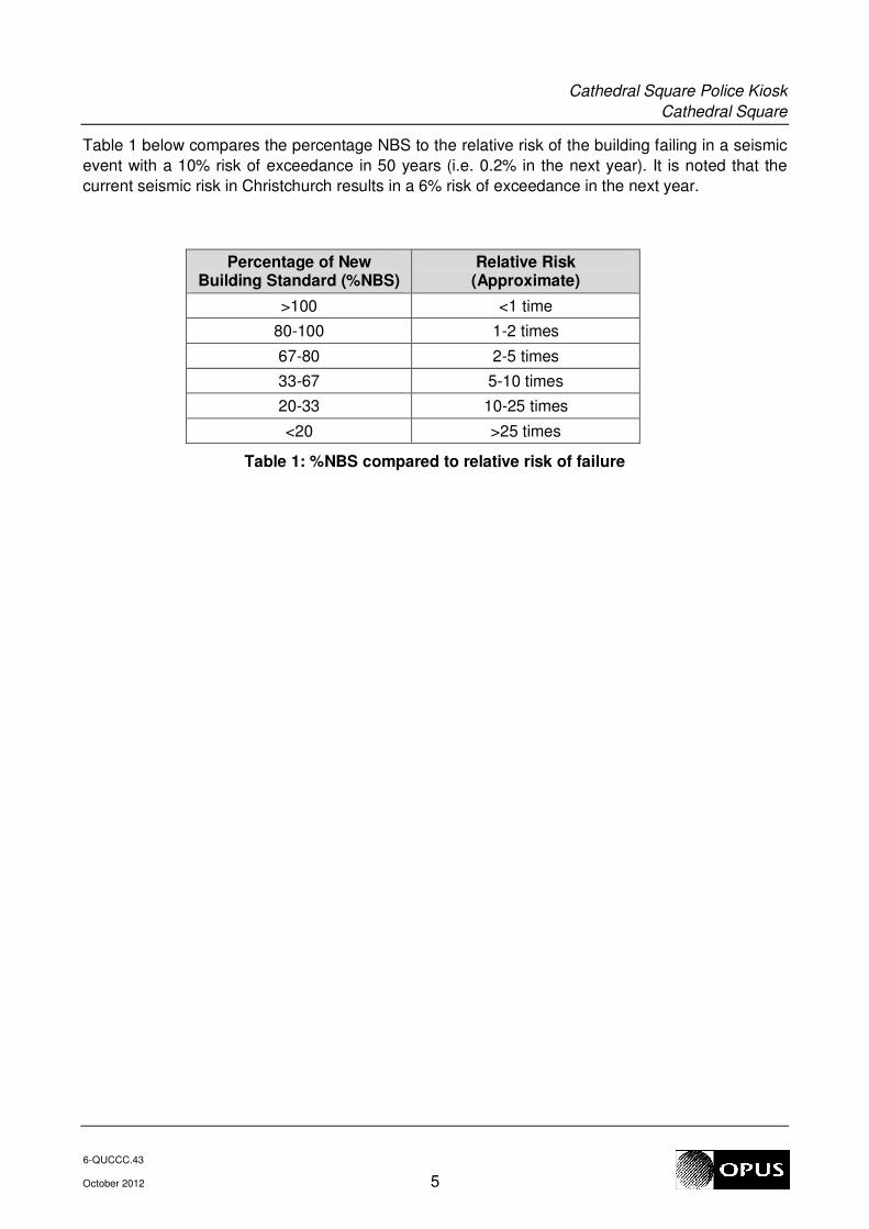
Table 1 below compares the percentage NBS to the relative risk of the building failing in a seismic
event with a 10% risk of exceedance in 50 years (i.e. 0.2% in the next year). It is noted that the
current seismic risk in Christchurch results in a 6% risk of exceedance in the next year.
Percentage of New Building Standard (%NBS)
Relative Risk (Approximate)
>100 <1 time
80-100 1-2 times
67-80 2-5 times
33-67 5-10 times
20-33 10-25 times
<20 >25 times
Table 1: %NBS compared to relative risk of failure

Cathedral Square Police Kiosk
Cathedral Square
6-QUCCC.43
October 2012 6
4 Background Information
4.1 Building Description
The Cathedral Square Police Kiosk is located in the northern half of Cathedral Square
around 30m south-west from the intersection of Worcester and Colombo Streets in Central
Christchurch. The building was constructed in 1973.
The kiosk is a single storey octagonal shaped reinforced concrete frame structure with a
pitched timber roof. The perimeter wall segments are 3.8m long, and the peak roof height
is 5.7m.
The building has rectangular 600x200mm precast concrete columns at each of the eight
vertices. A rectangular 300x250mm concrete tension ring beam runs between the
perimeter columns 2.4m above floor level. The roof has pitched glulam roof beams
supporting timber rafters under 10mm thick plywood sheathing. At the centre of the roof, the
pitched glulams are supported by a 100x100mm steel compression ring beam.
There are some partial and full height infill blockwork walls around the perimeter of the
kiosk. The only full height blockwork wall is on the east face of the kiosk. All other
perimeter faces have partial height blockwork. On the interior, there are also partial height
blockwork partitions.
The foundation system consists of spread footings connected around the perimeter by
200mm thick cast-in-place reinforced concrete ground beams with varying depths. The
ground beams have a single layer of reinforcing steel while the cast-in-place concrete
spread footings are unreinforced. The slab-on-grade is 100mm thick mesh reinforced in-
situ concrete.
Lateral load resistance is presumed to be provided by out-of-plane flexural cantilever action
in the columns. It has been assumed that bending about the strong axis did not contribute
to the lateral resistance of the kiosk. This is because there is only one dowel into the
unreinforced concrete footing, so it did not appear that the flexural strength of the column
could be developed at the base. In the weak direction, the columns are fixed on both sides
by the perimeter ground beams. The point of fixity is taken at the top of the grade beam.
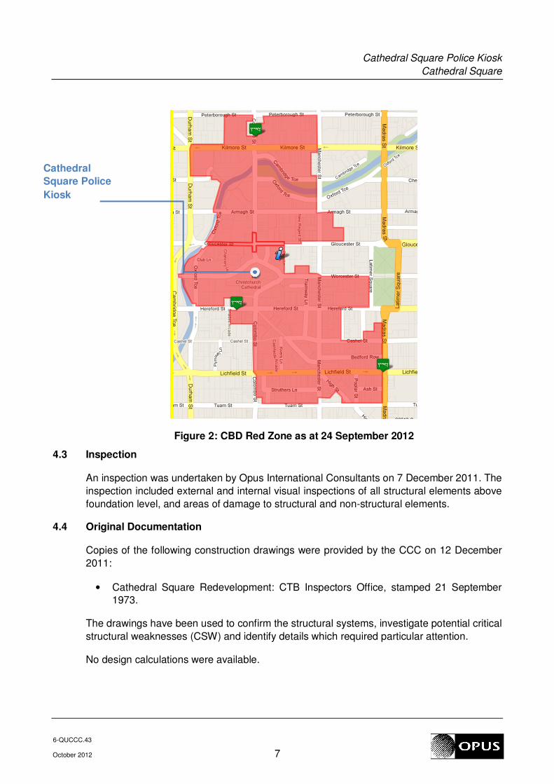
4.2 CBD Red Zone Cordon
Following the Lyttelton Earthquake of 22 February 2011, the central business district (CBD)
suffered major damage to a large proportion of its building stock and so a central area of
the city was cordoned off and closed to the public, forming what is known as the red zone.
Some outskirts of the red zone cordon have now been lifted and Oxford Terrace is currently
on the perimeter of the red zone. The red zone extent, as of 24 September 2012, is
displayed below in Figure 2.
Cathedral Square Police Kiosk
Cathedral Square
6-QUCCC.43
October 2012 7
Figure 2: CBD Red Zone as at 24 September 2012
4.3 Inspection
An inspection was undertaken by Opus International Consultants on 7 December 2011. The
inspection included external and internal visual inspections of all structural elements above
foundation level, and areas of damage to structural and non-structural elements.
4.4 Original Documentation
Copies of the following construction drawings were provided by the CCC on 12 December
2011:
• Cathedral Square Redevelopment: CTB Inspectors Office, stamped 21 September
1973.
The drawings have been used to confirm the structural systems, investigate potential critical
structural weaknesses (CSW) and identify details which required particular attention.
No design calculations were available.
Cathedral
Square Police
Kiosk

Cathedral Square Police Kiosk
Cathedral Square
6-QUCCC.43
October 2012 8
5 Structural Damage
Only very minor damage was observed to the kiosk. The damage noted is as follows:
• Cracking at the gib wall intersection with the pitched roof.
• 10-20mm differential settlement in the ground floor slab in the southeast corner.
6 General Observations
The kiosk appears to have performed well during the earthquakes. Only very minor damage was
noted to structural elements. The observed damage is consistent with the expected building
performance following a review of the structural drawings and site investigations.
7 Detailed Seismic Assessment
The detailed seismic assessment has been based on the NZSEE 2006 [2] guidelines for the
“Assessment and Improvement of the Structural Performance of Buildings in Earthquakes”
together with the Detailed Engineering Evaluation Procedure [3] (DEEP) document (draft) issued
by the Structural Engineering Society (SESOC) on 19 July 2011.
7.1 Critical Structural Weaknesses
The term Critical Structural Weakness (CSW) refers to a component of a building that could
contribute to increased levels of damage or cause premature collapse of a building. During
the initial qualitative stage of the assessment the following potential CSW was identified:
• Limited ductility in the lateral force resisting system.
7.2 Quantitative Assessment Methodology
Hand calculations were performed to assess the %NBS for various design actions resulting
from lateral loading. Because the building is expected to resist lateral load via cantilever
action in the weak direction of the columns, the building is expected to remain nominally
elastic. Lateral load demand was established in accordance with the static method in
NZS1170.5, with an updated Z factor of 0.3 (B1/VM1). Based on the actions determined
from the analyses, an assessment of the building capacities was made.
It was determined that weak axis bending in the columns controlled over strong axis
bending in the columns due to the detailing at the column base. Sheet 2 of the foundation
sheet shows only one dowel on one side of the column into the spread footing. Thus, the
column can only resist flexural loads in one direction. However in the weak axis, ground
beams frame into the column on either side, thus providing flexural rigidity. The point of
fixity was taken to be the top of the ground beams.
For each direction of loading, four columns resist the lateral load. Figure 3 shows an
example of loading in the north-south direction. In this case, two columns on the east and
two columns on the west resist the lateral load. Columns were checked for flexure, shear,
and drift.

Cathedral Square Police Kiosk
Cathedral Square
6-QUCCC.43
October 2012 9
In addition to the columns, there is one full height concrete masonry block wall on the east
side of the kiosk. Due to the stiffness of this lateral element, we checked the flexural and
shear capacity for the full base shear of the building.
The ring beam was checked to ensure that it could drag the lateral load into the lateral load
resisting columns. The dowels from the ring beam to the column were checked for shear
friction.
The moment from the columns is resisted by the ground beams on either side of the
columns. The moment is then resolved into a tension and compression couple which is
then taken into the spread footings below. The ground beams were checked for flexure and
shear. The shear demand at the intersection of the ground beam with the column was
checked against the shear friction capacity of the dowels.
The bearing pressure on the footings was determined by the resolving the lateral load
moment on the grade beams into an axial load on the footing and adding in the dead loads
from the roof. The moment and shear demand in the unreinforced concrete footing due to
the bearing pressure was checked against the unreinforced concrete capacities.
Figure 3: Lateral Load Distribution, North-South Direction
7.3 Limitations and Assumptions in Results
Our analysis and assessment is based on an assessment of the building in its undamaged
state. Given the low level of damage to the building, this assumption is not un-conservative.
The results have been reported as a %NBS and the stated value is that obtained from our
analysis and assessment. Despite the use of best national and international practice in this
analysis and assessment, this value contains uncertainty due to the many assumptions and
simplifications which are made during the assessment. These include:
− Simplifications made in the analysis, including boundary conditions such as
foundation fixity.
Cathedral Square Police Kiosk
Cathedral Square
6-QUCCC.43
October 2012 10
− Assessments of material strengths based on limited drawings, specifications and
site inspections
− The normal variation in material properties which change from batch to batch.
− Approximations made in the assessment of the capacity of each element, especially
when considering the post-yield behaviour.
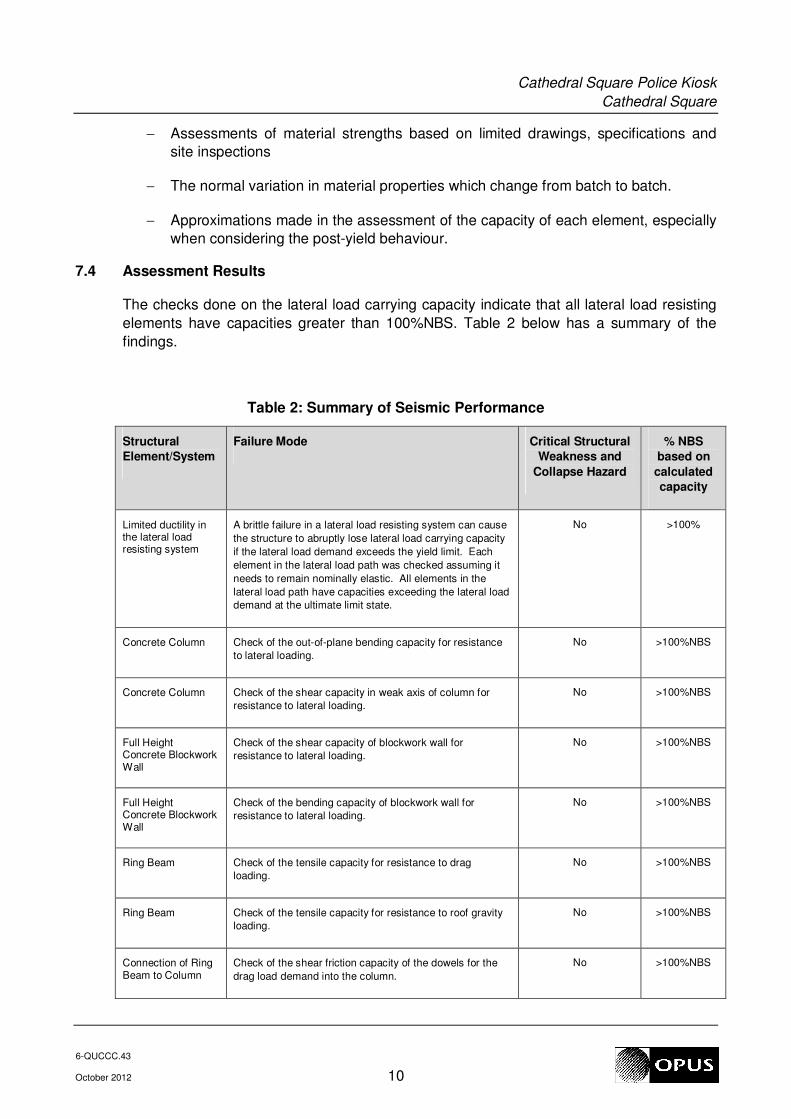
7.4 Assessment Results
The checks done on the lateral load carrying capacity indicate that all lateral load resisting
elements have capacities greater than 100%NBS. Table 2 below has a summary of the
findings.
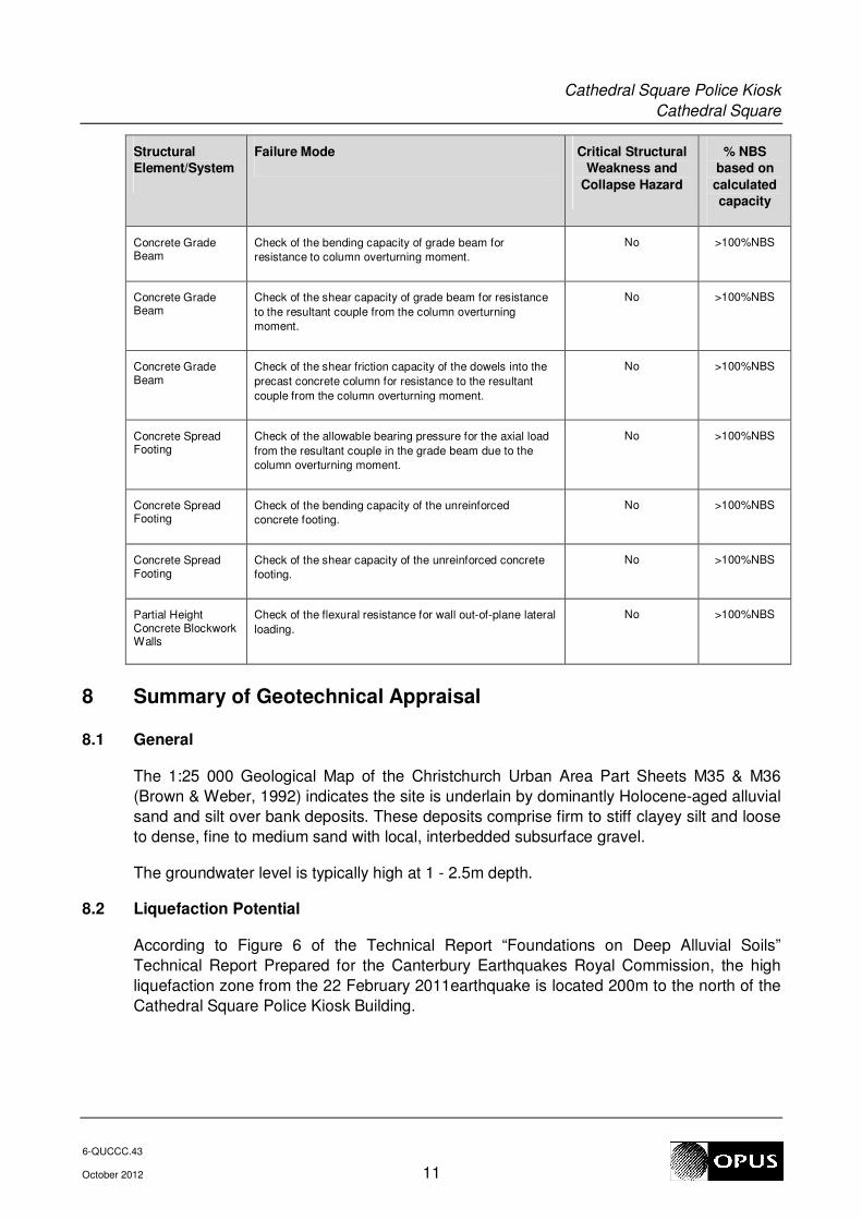
Table 2: Summary of Seismic Performance
Structural
Element/System
Failure Mode Critical Structural
Weakness and
Collapse Hazard
% NBS
based on
calculated
capacity
Limited ductility in the lateral load resisting system
A brittle failure in a lateral load resisting system can cause
the structure to abruptly lose lateral load carrying capacity
if the lateral load demand exceeds the yield limit. Each
element in the lateral load path was checked assuming it
needs to remain nominally elastic. All elements in the
lateral load path have capacities exceeding the lateral load
demand at the ultimate limit state.
No >100%
Concrete Column Check of the out-of-plane bending capacity for resistance
to lateral loading.
No >100%NBS
Concrete Column Check of the shear capacity in weak axis of column for
resistance to lateral loading.
No >100%NBS
Full Height Concrete Blockwork Wall
Check of the shear capacity of blockwork wall for
resistance to lateral loading.
No >100%NBS
Full Height Concrete Blockwork Wall
Check of the bending capacity of blockwork wall for
resistance to lateral loading.
No >100%NBS
Ring Beam Check of the tensile capacity for resistance to drag
loading.
No >100%NBS
Ring Beam Check of the tensile capacity for resistance to roof gravity
loading.
No >100%NBS
Connection of Ring Beam to Column
Check of the shear friction capacity of the dowels for the
drag load demand into the column.
No >100%NBS
Cathedral Square Police Kiosk
Cathedral Square
6-QUCCC.43
October 2012 11
Structural
Element/System
Failure Mode Critical Structural
Weakness and
Collapse Hazard
% NBS
based on
calculated
capacity
Concrete Grade Beam
Check of the bending capacity of grade beam for
resistance to column overturning moment.
No >100%NBS
Concrete Grade Beam
Check of the shear capacity of grade beam for resistance
to the resultant couple from the column overturning
moment.
No >100%NBS
Concrete Grade Beam
Check of the shear friction capacity of the dowels into the
precast concrete column for resistance to the resultant
couple from the column overturning moment.
No >100%NBS
Concrete Spread Footing
Check of the allowable bearing pressure for the axial load
from the resultant couple in the grade beam due to the
column overturning moment.
No >100%NBS
Concrete Spread Footing
Check of the bending capacity of the unreinforced
concrete footing.
No >100%NBS
Concrete Spread Footing
Check of the shear capacity of the unreinforced concrete
footing.
No >100%NBS
Partial Height Concrete Blockwork Walls
Check of the flexural resistance for wall out-of-plane lateral
loading.
No >100%NBS
8 Summary of Geotechnical Appraisal
8.1 General
The 1:25 000 Geological Map of the Christchurch Urban Area Part Sheets M35 & M36
(Brown & Weber, 1992) indicates the site is underlain by dominantly Holocene-aged alluvial
sand and silt over bank deposits. These deposits comprise firm to stiff clayey silt and loose
to dense, fine to medium sand with local, interbedded subsurface gravel.
The groundwater level is typically high at 1 - 2.5m depth.
8.2 Liquefaction Potential
According to Figure 6 of the Technical Report “Foundations on Deep Alluvial Soils”
Technical Report Prepared for the Canterbury Earthquakes Royal Commission, the high
liquefaction zone from the 22 February 2011earthquake is located 200m to the north of the
Cathedral Square Police Kiosk Building.

Cathedral Square Police Kiosk
Cathedral Square
6-QUCCC.43
October 2012 12
8.3 Conclusions
ECan well logs indicate the building is likely founded on a 3.7m to 11.5m thick layer of
GRAVEL (medium dense) possibly overlain by a shallow layer of fine SAND up to 1.75m
thick. The shallow foundations are likely within the gravel layer, which will provide some
liquefaction resilience.
No differential settlement or evidence of liquefaction was observed during the site walkover,
which reflects the expected ground conditions.
Based on the current external evidence, the existing shallow foundations are considered
appropriate for the building in ULS and SLS seismic events.
8.4 Recommendations
No further site investigations are recommended at this stage.
9 Remedial Options
No remedial options are required.
10 Conclusions
a) The seismic performance of the police kiosk exceeds 100%NBS. The building is
therefore considered to be of low risk in accordance with the NZSEE 2006 Guidelines
for Assessment and Improvement of the Structural Performance of Buildings in
Earthquakes.
b) Liquefaction hazard at the site is considered to be low, therefore the current shallow
foundations are considered appropriate.
11 Recommendations
a) It is recommended that the occupancy of the building be allowed to continue.
12 Limitations
a) This report is based on an inspection of the structure of the buildings and focuses on
the structural damage resulting from the 22 February Canterbury Earthquake and
aftershocks only. Some non-structural damage is described but this is not intended to
be a complete list of damage to non-structural items.
b) Our professional services are performed using a degree of care and skill normally
exercised, under similar circumstances, by reputable consultants practicing in this field
at this time.
c) This report is prepared for CCC to assist with assessing the remedial works required
for council buildings and facilities. It is not intended for any other party or purpose.
Cathedral Square Police Kiosk
Cathedral Square
6-QUCCC.43
October 2012 13
13 References
[1] NZS 1170.5: 2004, Structural design actions, Part 5 Earthquake actions, Standards
New Zealand.
[2] NZSEE: 2006, Assessment and improvement of the structural performance of
buildings in earthquakes, New Zealand Society for Earthquake Engineering.
[3] Engineering Advisory Group, Guidance on Detailed Engineering Evaluation of
Earthquake Affected Non-residential Buildings in Canterbury, Part 2 Evaluation
Procedure, Draft Prepared by the Engineering Advisory Group, Revision 5, 19 July
2011.
Cathedral Square Police Kiosk
Cathedral Square
6-QUCCC.43
October 2012
Appendix 1 – Photographs
Cathedral Square Police Kiosk
Cathedral Square
6-QUCCC.43
October 2012
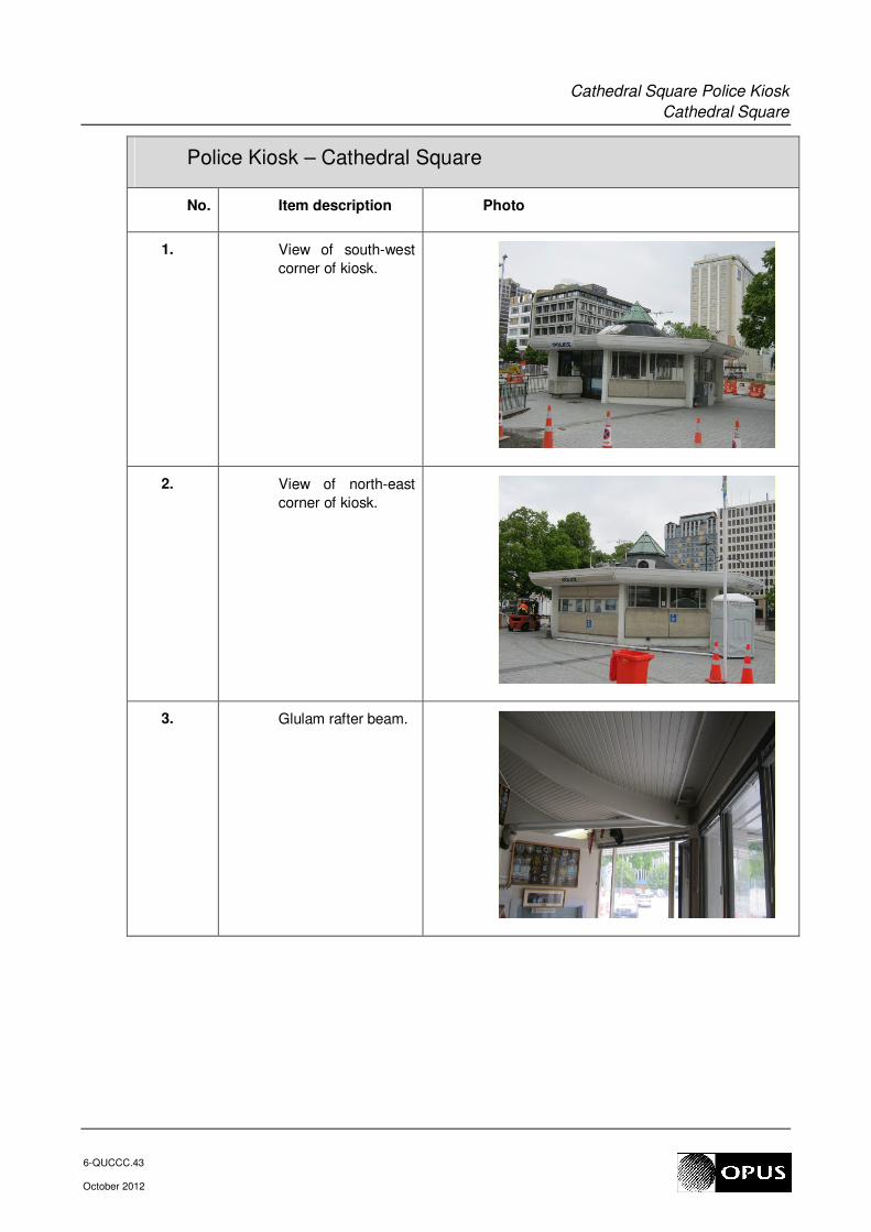
Police Kiosk – Cathedral Square
No. Item description Photo
1. View of south-west
corner of kiosk.
2. View of north-east
corner of kiosk.
3. Glulam rafter beam.

Cathedral Square Police Kiosk
Cathedral Square
6-QUCCC.43
October 2012
4. Connection of
glulam rafter to
precast column.
5. Interface of partial
height blockwork
walls and precast
column.
6. Steel compression
ring beam.
7. Cracking at the
intersection of the
partition wall with the
ceiling.

Cathedral Square Police Kiosk
Cathedral Square
6-QUCCC.43
October 2012
Appendix 2 – Geotechnical Appraisal

Opus International Consultants Limited 20 Moorhouse Avenue Telephone: +64 3 363 5400 Christchurch Office PO Box 1482, Christchurch Mail Centre, Facsimile: +64 3 365 7858 Christchurch 8140, New Zealand Website: www.opus.co.nz
15 December 2011 Lindsay Fleming Christchurch City Council 53 Hereford St PO Box 237 Christchurch 8140
6-QUCCC.43/005SC
Dear Lindsay Cathedral Square Police Kiosk - Geotechnical Desktop Appraisal 1. Introduction
The Cathedral Square Police Kiosk was subjected to severe ground shaking during the Darfield 2010 and Christchurch 2011 earthquakes and subsequent aftershocks. This report summarises the findings of a geotechnical desk study and site walkover completed by Opus International Consultants (Opus) for the Christchurch City Council (CCC) on 1 November 2011. This desk study assesses the ground conditions and performance of the building and identifies potential geotechnical hazards that may be present. It is our understanding this is the first inspection by a Geotechnical Engineer following the earthquakes. A structural inspection was carried out by Opus on 12 October 2011. 2. Desktop Study
2.1 Site Description
The Police Kiosk is located on the northern half of Cathedral Square around 30m south west from the intersection of Worcester and Colombo Streets. The ground profile is flat, level with the surrounding streets and Cathedral Square area. All surfaces in the vicinity of the kiosk are paved or asphalted. 2.2 Regional Geology
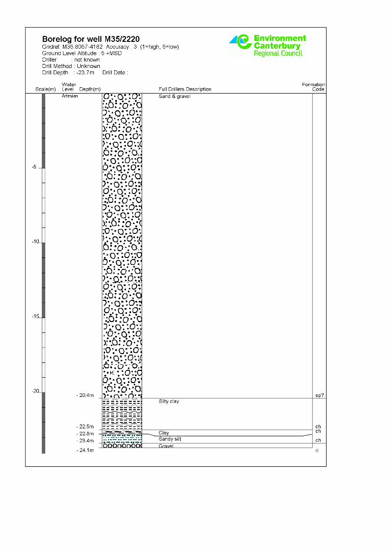
The 1:25 000 Geological Map of the Christchurch Urban Area Part Sheets M35 & M36 (Brown & Weber, 1992) indicates the site is underlain by dominantly Holocene-aged alluvial sand and silt over bank deposits. These deposits comprise firm to stiff clayey silt and loose to dense, fine to medium sand with local, interbedded subsurface gravel. The groundwater level is typically 1m - 2.5m below ground level (bgl). 2.3 Ground Conditions
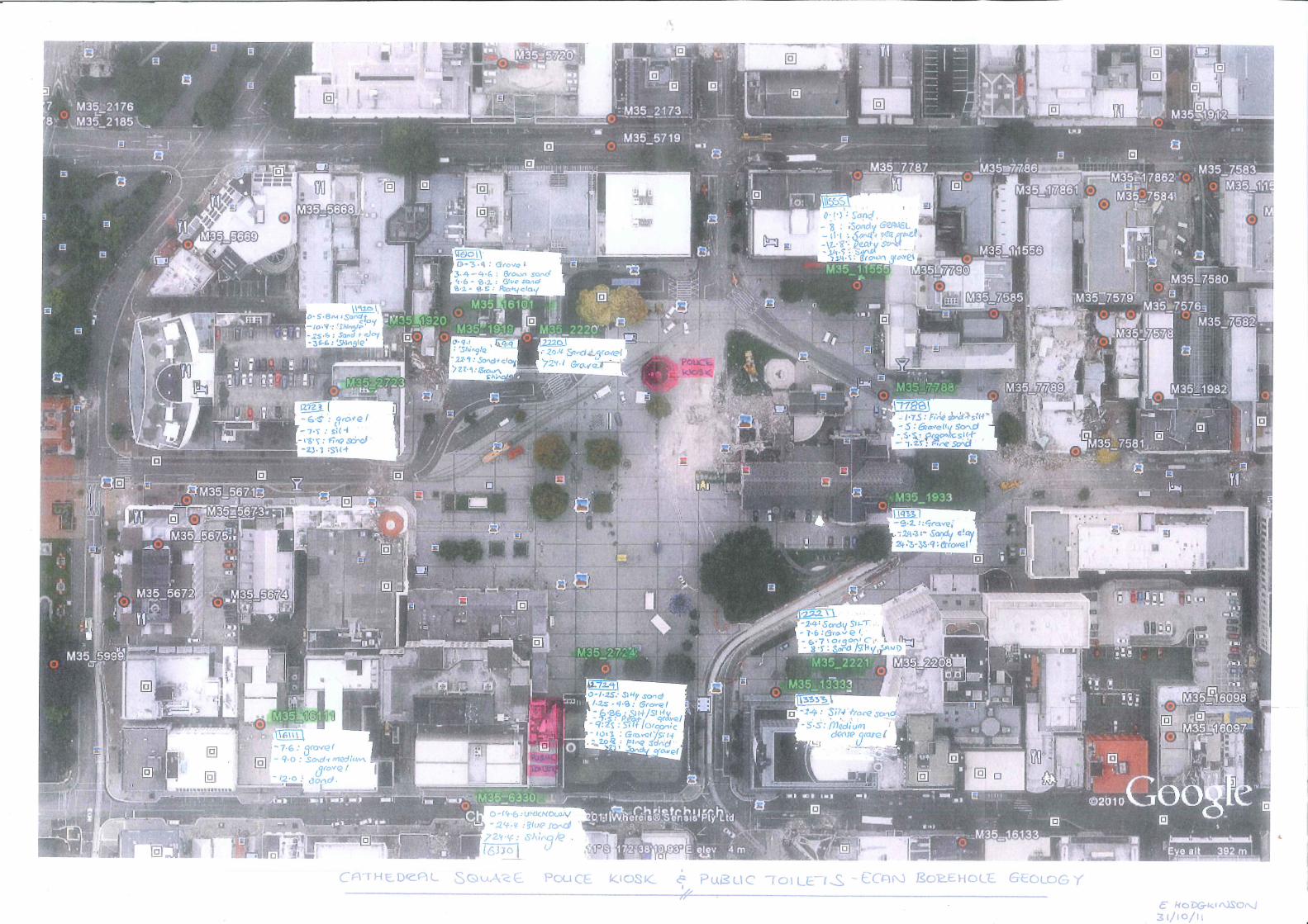
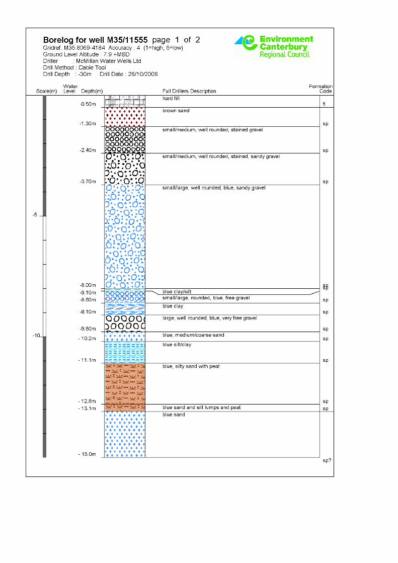
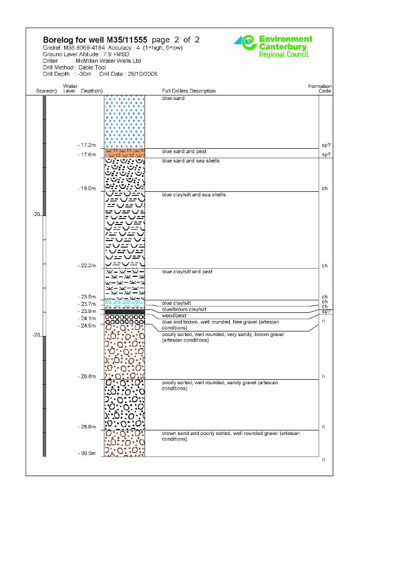
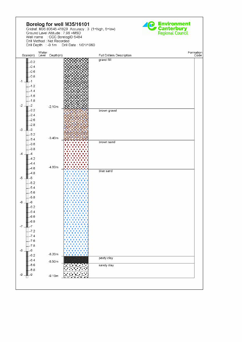
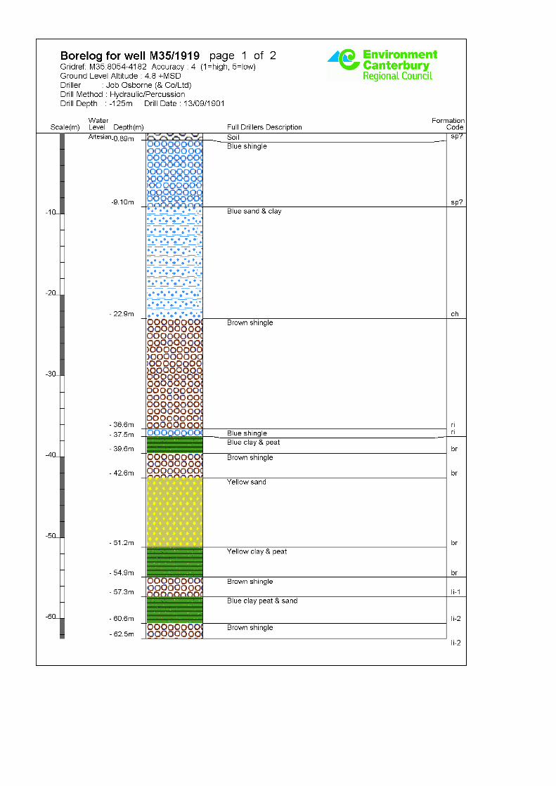
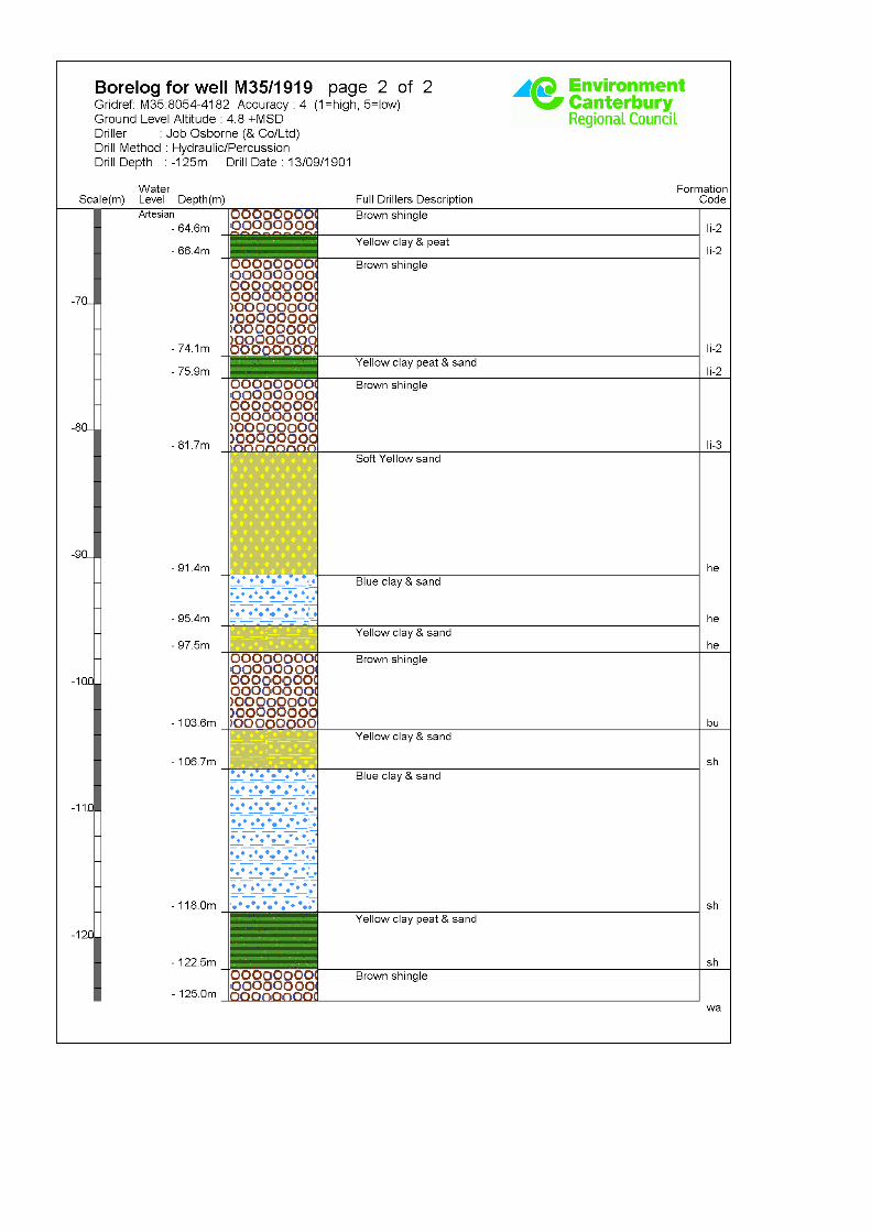
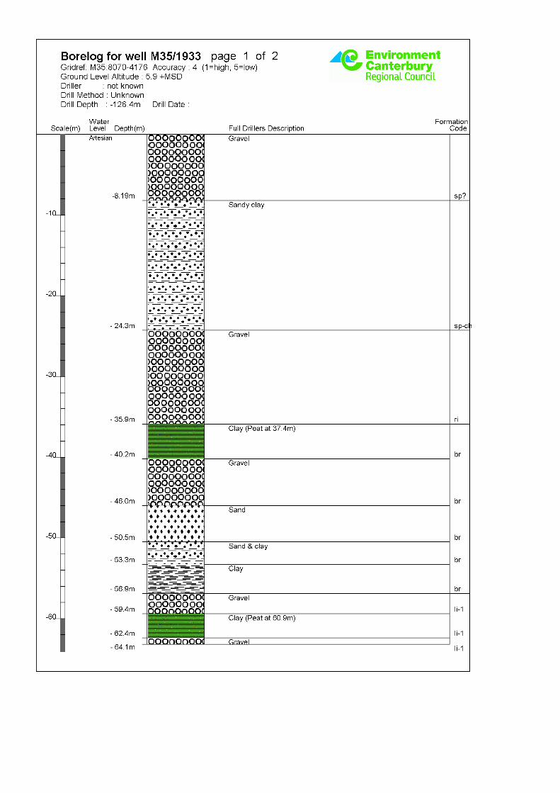
Seven well logs were selected from the Environment Canterbury (ECan) website that are in close proximity to the Police Kiosk. The following ground conditions are interpreted from the ECan logs near the kiosk building site:

Page - 2
Stratigraphy Thickness (m) Initial Depth
Encountered From (m) bgl
Fine SAND 1.3 – 1.75 0
GRAVEL / Sandy GRAVEL 3.7 – 11.5 1.25 – 2.4
SILT / Fine SAND 14.9 – 16.8 6.5 - 10.7
Gravel (Riccarton) - 24 – 25.6
Table 1 Interpreted Ground Conditions
The approximate locations of the boreholes relative to the Police Kiosk are shown on the attached Site Location Plan. The logs of the ECan borehole records are also included in Appendix A.
Groundwater is described in the logs as artesian but no exact water levels were found in these logs or others in the vicinity.
No CPT data was identified near the site. 2.4 Ground Damage
No evidence of liquefaction was observed in aerial photographs in the immediate vicinity of the Police Kiosk taken after the 4 September 2010 and 22 February 2011 earthquakes. According to Figure 6 of the Technical Report “Foundations on Deep Alluvial Soils” Technical Report Prepared for the Canterbury Earthquakes Royal Commission, the high liquefaction zone from the 22 February 2011earthquake is located approximately 200m north of the Cathedral Square Police Kiosk Building. A walkover inspection of the exterior and interior of the building was completed by Emily Hodgkinson, an Opus Geotechnical Engineer on 3 November 2011.
There was no sign of liquefaction or significant differential settlement of the Police Kiosk observed during the walkover survey. The interior floor level in the eastern corner of the south east room in the kiosk appeared to be higher than the rest of the room by approximately 10mm to 20mm. There was no sign of differential settlement observed in the perimeter of the building foundation. The possible ground heave appears to be isolated and it is not conclusive if the heave is associated with liquefaction.
There appears to be no damage to the building has resulted from settlement or liquefaction. Lateral spreading is not considered to be a risk at this site.
2.5 Structural Drawings
Structural drawings of the police kiosk dated September 1973 have been obtained. The building is single level and comprises one octagonal structure in plan. The building is a reinforced concrete frame, with concrete wall frames, a concrete ring beam around the top of walls and a timber glulam beam roof structure. The drawings indicate the internal walls and floor slab are supported on strip footings around 400mm deep and 100mm to 150mm wide. Shallow reinforced concrete piles


Page - 4
Photos of the Cathedral Square Police Kiosk Building taken 3 November 2011
Photograph 1. View of the Police Kiosk looking north towards Colombo Street.
Photograph 2. Internal view of the east side of the Police Kiosk, where around 10-20mm elevation in floor level was observed (position shown in Photograph 1)
Photograph 2 location
Page - 5
APPENDIX A: ECAN BOREHOLE LOGS


Cathedral Square Police Kiosk
Cathedral Square
6-QUCCC.43
October 2012
Appendix 3 – CERA DEE Spreadsheet
Detailed Engineering Evaluation Summary Data V1.11
Location
Building Name: Cathedral Square Police Kiosk Reviewer: Alistair Boyce
Unit No: Street CPEng No: 209860
Building Address: Cathedral Square Company: Opus International Consultants
Legal Description: Company project number: 6QUCCC.43
Company phone number: 03 363 5400
Degrees Min Sec
GPS south: Date of submission: 16-Oct-12
GPS east: Inspection Date: 7-Dec-11
Revision: Final
Building Unique Identifier (CCC): BU 1217-001 EQ2 Is there a full report with this summary? yes
Site
Site slope: flat Max retaining height (m):
Soil type: Soil Profile (if available):
Site Class (to NZS1170.5): D
Proximity to waterway (m, if <100m): If Ground improvement on site, describe:
Proximity to clifftop (m, if < 100m):
Proximity to cliff base (m,if <100m): Approx site elevation (m): 10.00
Building
No. of storeys above ground: 1 single storey = 1 Ground floor elevation (Absolute) (m):
Ground floor split? no Ground floor elevation above ground (m):
Storeys below ground
Foundation type: strip footings if Foundation type is other, describe:
Building height (m): 5.70 height from ground to level of uppermost seismic mass (for IEP only) (m): 6Floor footprint area (approx):
Age of Building (years): 39 Date of design: 1965-1976
Strengthening present? no If so, when (year)?
And what load level (%g)?
Use (ground floor): commercial Brief strengthening description:
Use (upper floors):Use notes (if required):
Importance level (to NZS1170.5): IL2
Gravity Structure
Gravity System: frame system
Roof: timber framed rafter type, purlin type and cladding TimberFloors:
Beams: timber type Glulam
Columns: precast concrete typical dimensions (mm x mm) 600x200
Walls: partially filled concrete masonry thickness (mm) 190
Lateral load resisting structure
Lateral system along: other (note) describe system Cantilevered columnsDuctility assumed, µ: 1.25
Period along: 0.50 0.00 estimate or calculation?
Total deflection (ULS) (mm): estimate or calculation?
maximum interstorey deflection (ULS) (mm): estimate or calculation?
Lateral system across: other (note) describe system Cantilevered columnsDuctility assumed, µ: 1.25
Period across: 0.50 0.00 estimate or calculation?
Total deflection (ULS) (mm): estimate or calculation?
maximum interstorey deflection (ULS) (mm): estimate or calculation?
Separations:
north (mm): leave blank if not relevant
east (mm):
south (mm):
west (mm):
Non-structural elements
Stairs:
Wall cladding: exposed structure describe
Roof Cladding: Other (specify) describe Butynol over plywood
Glazing: aluminium frames
Ceilings:
Services(list):
Available documentation
Architectural full original designer name/date
Structural full original designer name/date CTB Inspectors Office, September 1973
Mechanical none original designer name/date
Electrical none original designer name/date
Geotech report original designer name/date
Damage
Site: Site performance: Describe damage:
(refer DEE Table 4-2)
Settlement: 0-25mm notes (if applicable): 20mm settlement at south-east corner
Differential settlement: 0-1:350 notes (if applicable):
Liquefaction: notes (if applicable):
Lateral Spread: none apparent notes (if applicable):
Differential lateral spread: none apparent notes (if applicable):
Ground cracks: notes (if applicable):
Damage to area: notes (if applicable):
Building:
Current Placard Status: green
Along Damage ratio: Describe how damage ratio arrived at:
Describe (summary):
Across Damage ratio: #DIV/0!
Describe (summary):
Diaphragms Damage?: no Describe:
CSWs: Damage?: no Describe:
Pounding: Damage?: no Describe:
Non-structural: Damage?: yes Describe: Cracking of internal gib board walls
Recommendations
Level of repair/strengthening required: none Describe:
Building Consent required: no Describe:
Interim occupancy recommendations: full occupancy Describe:
Along Assessed %NBS before: ##### %NBS from IEP below Quantitative
Assessed %NBS after: 100%
Across Assessed %NBS before: ##### %NBS from IEP below
Assessed %NBS after: 100%
IEP Use of this method is not mandatory - more detailed analysis may give a different answer, which would take precedence. Do not fill in fields if not using IEP.
Period of design of building (from above): 1965-1976 hn from above: 6m
Seismic Zone, if designed between 1965 and 1992: not required for this age of building
not required for this age of building
along across
Period (from above): 0.5 0.5
(%NBS)nom from Fig 3.3:
Note:1 for specifically design public buildings, to the code of the day: pre-1965 = 1.25; 1965-1976, Zone A =1.33; 1965-1976, Zone B = 1.2; all else 1.0
Note 2: for RC buildings designed between 1976-1984, use 1.2
Note 3: for buildngs designed prior to 1935 use 0.8, except in Wellington (1.0)
along across
Final (%NBS)nom: 0% 0%
2.2 Near Fault Scaling Factor Near Fault scaling factor, from NZS1170.5, cl 3.1.6:
along across
Near Fault scaling factor (1/N(T,D), Factor A: #DIV/0! #DIV/0!
2.3 Hazard Scaling Factor Hazard factor Z for site from AS1170.5, Table 3.3:
Z1992, from NZS4203:1992
Hazard scaling factor, Factor B: #DIV/0!
2.4 Return Period Scaling Factor Building Importance level (from above): 2
Return Period Scaling factor from Table 3.1, Factor C: 1.00
along across
2.5 Ductility Scaling Factor Assessed ductility (less than max in Table 3.2)
Ductility scaling factor: =1 from 1976 onwards; or =kµ, if pre-1976, fromTable 3.3:
Ductiity Scaling Factor, Factor D: 0.00 0.00
2.6 Structural Performance Scaling Factor: Sp:
Structural Performance Scaling Factor Factor E: #DIV/0! #DIV/0!
2.7 Baseline %NBS, (NBS%)b = (%NBS)nom x A x B x C x D x E %NBSb: #DIV/0! #DIV/0!
Global Critical Structural Weaknesses: (refer to NZSEE IEP Table 3.4)
3.1. Plan Irregularity, factor A: insignificant 1
3.2. Vertical irregularity, Factor B: insignificant 1
3.3. Short columns, Factor C: insignificant 1
3.4. Pounding potential Pounding effect D1, from Table to right 1.0
Height Difference effect D2, from Table to right 1.0
Therefore, Factor D: 1
3.5. Site Characteristics insignificant 1
Along Across
3.6. Other factors, Factor F For ≤ 3 storeys, max value =2.5, otherwise max valule =1.5, no minimum
Rationale for choice of F factor, if not 1
Detail Critical Structural Weaknesses: (refer to DEE Procedure section 6)
List any: Refer also section 6.3.1 of DEE for discussion of F factor modification for other critical structural weaknesses
3.7. Overall Performance Achievement ratio (PAR) 0.00 0.00
4.3 PAR x (%NBS)b: PAR x Baselline %NBS: #DIV/0! #DIV/0!
4.4 Percentage New Building Standard (%NBS), (before) #DIV/0!
Note: Define along and across in
detailed report!
If IEP not used, please detail assessment
methodology:
Table for selection of D1 Severe Significant Insignificant/none
Separation 0<sep<.005H .005<sep<.01H Sep>.01H
Alignment of floors within 20% of H 0.7 0.8 1
Alignment of floors not within 20% of H 0.4 0.7 0.8
Table for Selection of D2 Severe Significant Insignificant/none
Separation 0<sep<.005H .005<sep<.01H Sep>.01H
Height difference > 4 storeys 0.4 0.7 1
Height difference 2 to 4 storeys 0.7 0.9 1
Height difference < 2 storeys 1 1 1
)(%
))(%)((%_
beforeNBS
afterNBSbeforeNBSRatioDamage
−=


