1
DEVELOPMENT OF A PID CONTROLLER FOR DC MOTOR USING
MICROSOFT VISUAL BASIC
MOHD AIZUDDIN BIN ABU BAKAR
A report submitted in partial fulfillment of the
requirements for the award of the degree of
Bachelor of Electrical (Electronics) Engineering
Faculty of Electrical and Electronics Engineering
Universiti Malaysia Pahang
NOVEMBER 2008

2

4
“I hereby acknowledge that the scope and quality of this thesis is qualified for the award of
the Bachelor Degree of Electrical Engineering (Electronics)”
Signature : ______________________
Name : HASZURAIDAH BINTI ISHAK
Date : 17 NOVEMBER 2008
DEVELOPMENT OF A PID CONTROLLER FOR DC MOTOR USING
MICROSOFT VISUAL BASIC

5
MOHD AIZUDDIN BIN ABU BAKAR
A report submitted in partial fulfillment of the
requirements for the award of the degree of
Bachelor of Electrical (Electronics) Engineering
Faculty of Electrical and Electronics Engineering
Universiti Malaysia Pahang
NOVEMBER 2008
I declare this thesis entitled Develop a PID controller for DC motor using Microsoft
Visual Basic is the result of my own research except as cited in the references. This
thesis has not been accepted for any degree and is not concurrently submitted in
candidature of any other degree

6
Signature: _________________________________
Name: MOHD AIZUDDIN BIN ABU BAKAR
Date: 17 NOVEMBER 2008

7
ACKNOLEDGEMENT
I am greatly indebted to my supervisor, Puan Haszuraidah binti Ishak for her
advice and guidance throughout my project. Thank you.
I would like to thank my family member for giving me their loves and supports
throughout my study in Universiti Malaysia Pahang.
Special thanks to FKEE staffs for helping me to complete my project.
Suggestions and criticisms from my friends have always been helpful in finding
solutions to my problems. Thank you all.
Finally, I would like to express my thanks to those who involves directly or
indirectly in completion of my project.
ABSTRACT

8
This main of this project is to develop a PID (Proportional, Integral, Derivatives)
controller and interface with a device. The controller is PID and the software is
Microsoft Visual Basic 6.0. The MATLAB software is used for simulation of this
system. The methodology is divided into two parts which is software and hardware. The
first part is simulation for this system by using Matlab software to determine the value
of Kp, Ki and Kd. The range value for PID is determined by using Ziegler Nichols
method. For second part is to interface the controller with hardware. The controller is
using Microsoft visual basic 6.0 software. Then, the controller need to interface with
DAQ card first. After interfacing success, the system can be implementing to servo
motor. The feedback value can be received from servo motor encoder. After finished the
first and second part, this system can be tuned up by using the PID value from
simulation.
ABSTRAK
Tujuan utama projek ini adalah untuk membangunkan sebuah pengawal PID
(Proportional, Integral, Derivatives) yang boleh berantaramuka dengan peralatan.
Pengawal yang digunakan adalah PID dan perisian yang digunakan adalah Microsoft

9
Visual Basic 6.0. Perisian Matlab digunakan untuk membuat simulasi pada sistem ini.
Metodologi dibahagikan kepada dua bahagian iaitu perkakasan dan perisian. Bahagian
pertama adalah simulasi kepada sistem ini dengan menggunakan perisian Matlab untuk
menentukan nilai Kp, Kid an Kd. Julat nilai PID ditentukan dengan menggunakan
kaedah Ziegler Nicholes. Bahagian kedua adalah untuk antaramuka dantara pengawal
dan perkakasan.Pengawal menggunakan perisian Microsoft Visual Basic 6.0.
Kemudian, pengawal perlu berantaramuka dengan kad DAQ (Data Acquisition).
Selepas berjaya berantaramuka, sistem ini akan diimplementasikan pada motor servo.
Nilai suapbalik akan diterima dari pengekod motor servo. Setelah selesai bahagian
pertama dan kedua, sistem ini akan dilaraskan dengan menggunakan nilai PID dari
proses simulasi.
TABLE OF CONTENTS
CHAPTER TITLE PAGE

10
1
2
3
INTRODUCTION
1.1 Overview
1.2 Project Objectives
1.3 Scope of Project
1.4 Problem Statement
1.5 Thesis Organization
LITERATURE REVIEW
2.1 PID controller
2.2 Direct Current motor
2.3 Microsoft Visual Basic 6.0
2.4 Data acquisition card
METHODOLGY
3.1 Introduction
3.2 Hardware development
3.2.1. Servo motor
3.2.2. Modelling DC servo motor
3.2.3. DAQ card
3.3 Software Development
3.3.1. Matlab
3.3.2. Microsoft Visual Basic 6.0
3.3.3. PID Method
1
1
2
2
3
3
4
4
7
8
9
11
11
14
16
17
20
21
21
21
23
11
4
5
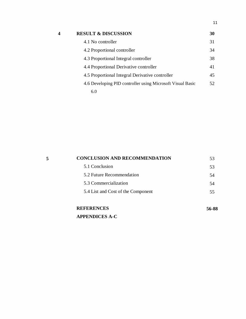
RESULT & DISCUSSION
4.1 No controller
4.2 Proportional controller
4.3 Proportional Integral controller
4.4 Proportional Derivative controller
4.5 Proportional Integral Derivative controller
4.6 Developing PID controller using Microsoft Visual Basic
6.0
CONCLUSION AND RECOMMENDATION
5.1 Conclusion
5.2 Future Recommendation
5.3 Commercialization
5.4 List and Cost of the Component
REFERENCES
APPENDICES A-C
30
31
34
38
41
45
52
53
53
54
54
55
56-88
12
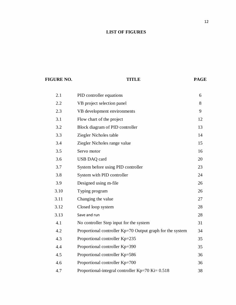
LIST OF FIGURES
FIGURE NO.
TITLE PAGE
2.1
2.2
2.3
3.1
3.2
3.3
3.4
3.5
3.6
3.7
3.8
3.9
3.10
3.11
3.12
3.13
4.1
4.2
4.3
4.4
4.5
4.6
4.7
PID controller equations
VB project selection panel
VB development environments
Flow chart of the project
Block diagram of PID controller
Ziegler Nicholes table
Ziegler Nicholes range value
Servo motor
USB DAQ card
System before using PID controller
System with PID controller
Designed using m-file
Typing program
Changing the value
Closed loop system
Save and run
No controller Step input for the system
Proportional controller Kp=70 Output graph for the system
Proportional controller Kp=235
Proportional controller Kp=390
Proportional controller Kp=586
Proportional controller Kp=700
Proportional-integral controller Kp=70 Ki= 0.518
6
8
9
12
13
14
15
16
20
23
24
26
26
27
28
28
31
34
35
35
36
36
38

13
4.8
4.9
4.10
4.11
4.12
4.13
41.4
4.15
4.16
4.17
4.18
4.19
4.20
4.21
4.22
4.23
Proportional-integral controller Kp=700 Ki= 0.518
Proportional-integral controller Kp=70 Ki= 51.8
Proportional-integral controller Kp=700 Ki= 51.8
Proportional-derivative controller Kp=140 Kd= 2.59
Proportional-derivative controller Kp=700 Kd= 2.59
Proportional-derivative controller Kp=140 Kd= 51.8
Proportional-derivative controller Kp=700 Kd= 51.8
PID controller Kp=70 Ki=5.18 Kd=2.59
PID controller Kp=700 Ki=5.18 Kd=2.59
PID controller Kp=70 Ki=518 Kd=51.8
PID controller Kp=700 Ki=518 Kd=51.8
PID controller Kp=70 Ki=5.18 Kd=51.8
PID controller Kp=700 Ki=5.18 Kd=51.8
PID controller Kp=70 Ki=518 Kd=2.59
PID controller Kp=700 Ki=518 Kd=2.59
PID controller using Microsoft Visual Basic 6.0
39
39
40
42
42
43
43
45
46
46
47
48
48
49
50
52

14
LIST OF EQUATIONS
FIGURE NO.
3.1
3.2
3.3
3.4
3.5
3.6
3.7
4.1
4.2
4.3
PAGE
17
17
17
18
18
18
19
31
32
32
15
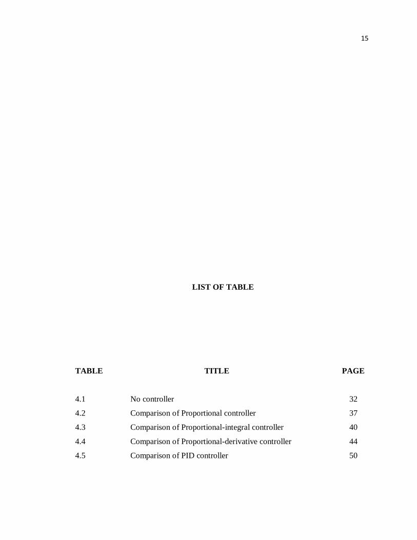
LIST OF TABLE
TABLE
TITLE PAGE
4.1
4.2
4.3
4.4
4.5
No controller
Comparison of Proportional controller
Comparison of Proportional-integral controller
Comparison of Proportional-derivative controller
Comparison of PID controller
32
37
40
44
50

16
LIST OF APPENDICES
APPENDIX
TITLE PAGE
A
B
C
DAQ card manual
Servo motor manual installation
Microsoft Visual Basic programmed
30
52
61

17

18
CHAPTER 1
INTRODUCTION
1.1 Overview
In 18th century, James Watt invented the flyball speed governer to control the
speed of steam engines. In this device, two spinning fliballs rise as rotational speed
increases. A steam valve connected to the flyball mechanism closes with the ascending
flyballs and opens with the descending flyballs, thus regulating the speed.
PID Control (proportional-integral-derivative) is by far the widest type of
automatic control used in industry nowadays. Even though it has a relatively simple
algorithm/structure, there are many subtle variations in how it is applied in industry. PID
control action allows the process control to accurately maintain set point by adjusting
the control outputs.
In order to eliminate this problem, PID controller is introduce to the system.
There‟s few type of controller but in this project, PID controller is chosen to interfaces

19
with the DC motor. This is because PID controller helps get the output, where we want
it in a short time, with minimal overshoot and little error.
1.2 Project Objectives
At the end of this project:-
i. To develop a PID controller design for DC motor speed using Microsoft
visual basic.
ii. To control the speed of DC motor with PID controller using Microsoft
Visual Basic (Design the PID controller and tune it).
1.3 Scope of Project
The scope of this project is:-
i. To derive mathematical model of dc motor and develop PID controller
for the motor.
ii. To develop GUI in Vb as an environment to applied the PID controller
for the motor.
iii. Perform computer simulation of the PID controller by using Matlab
simulink to investigate the effectiveness of PID controller.

20
1.4 Problem Statements
The speed controller works by varying the average voltage sent to the motor. It
could do this by simply adjusting the voltage sent to the motor, but this is quite
inefficient to do.
A better way is to switch the motor's supply on and off very quickly. However, if the
switching is fast enough, the motor doesn't notice it, it only notices the average effect.
By using PID controller, it can overcome this problems because it is sensitive to
disturbances and able to correct this error quickly.
1.5 Thesis Organization
This thesis will consist of five chapters including this chapter. The contents of
each chapter are outlined as follows;
Chapter 2 will present the detailed description of the PID system, Microsoft
Visual Basic software, DC motor and DAQ card. Chapter 3 will describe the
methodology used in the project, including how the project is organized and flow of the
project. Chapter 4 will discuss about the results and all of this will be concluded in
Chapter 5.

21
CHAPTER 2
LITERATURE REVIEW
2.1 PID controller
The PID controller (Proportional, Integral and Derivative) has been known for
several decades in many fields of automatic control. It has had powerful applications
and several modifications anywhere where automatic control has been applicable. In
spite of its many modified structures and forms the basic idea has remained the same.
The underlying working principle relies on feedback control and the PID controller is
the most common embodiment of feedback control. It involves three different terms,
each of which have a specific purpose. Proportional and integral terms were known in
the 1930s but derivative control was not invented until the 1940s. In basic terms, the
PID controller is a numerical recipe, an algorithm. The algorithm may be implemented,
that is, programmed using any programming language supporting numerical
computation. It can be written in Visual Basic, Fortran, Pascal, C or Java. Also, there are
numerous platforms for the algorithm such as personal computers, distributed control
systems (DCS), programmable logic controllers (PLC), and field devices or microchips

22
enabling embedded solutions. In spite of the PID controller syntax language and its
platform or even application, there are some essential features that should be involved in
the PID controller algorithm: The basic calculation covering arithmetic around three
different terms is not enough. Other issues of automatic feedback control must also be
taken care of. In addition to this, there are potential characteristics that may be added to
increase functionality and to improve applicability of the PID controller. There are
different types of PID controllers such as ratio, cascade or split range controllers -and
there are different algorithm types such as position or incremental (velocity) algorithms.
The position algorithms can be categorized into ISA, series and parallel algorithms. The
most typical operation modes for PID controllers are automatic, manual, cascade and
remote. Some manufacturers hide their algorithms, but they should be available so that
users can properly tune the instrument. The PID controller is not a secret and it should
not he treated as one, although it is very rare for the numerical robustness of the
algorithm to be available at all.[1]
A proportional–integral–derivative controller (PID controller) is a generic control
loop feedback mechanism widely used in industrial control systems. A PID controller
attempts to correct the error between a measured process variable and a desired set point
by calculating and then outputting a corrective action that can adjust the process
accordingly.[2]
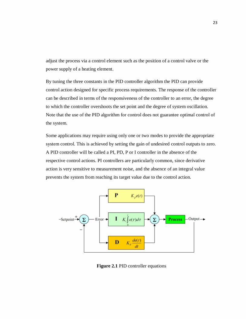
Figure 2.1 shows the PID controller calculation (algorithm) involves three separate
parameters; the Proportional, the Integral and Derivative values. The Proportional value
determines the reaction to the current error, the Integral determines the reaction based
on the sum of recent errors and the Derivative determines the reaction to the rate at
which the error has been changing. The weighted sum of these three actions is used to
23
adjust the process via a control element such as the position of a control valve or the
power supply of a heating element.
By tuning the three constants in the PID controller algorithm the PID can provide
control action designed for specific process requirements. The response of the controller
can be described in terms of the responsiveness of the controller to an error, the degree
to which the controller overshoots the set point and the degree of system oscillation.
Note that the use of the PID algorithm for control does not guarantee optimal control of
the system.
Some applications may require using only one or two modes to provide the appropriate
system control. This is achieved by setting the gain of undesired control outputs to zero.
A PID controller will be called a PI, PD, P or I controller in the absence of the
respective control actions. PI controllers are particularly common, since derivative
action is very sensitive to measurement noise, and the absence of an integral value
prevents the system from reaching its target value due to the control action.
Figure 2.1 PID controller equations

24
2.2 Direct current motor
Almost every mechanical movement is caused by a DC (direct current) electric
motor. An electric motor is a device that transforms electrical energy into mechanical
energy by using the motor effect.
Every DC motor has six basic parts which is axle, rotor (armature), stator,
commutator, field magnet, and brushes. In most common DC motors, the external
magnetic field is produced by high-strength permanent magnets. The stator is the
stationary part of the motor which includes the motor casing, as well as two or more
permanent magnet pole pieces. The rotor rotates with respect to the stator. The rotor
consists of windings and the windings being electrically connected
to the commutator .Industrial applications use dc motors because the speed-torque
relationship can be varied to almost any useful form which is for both dc motor and
regeneration applications in either direction of rotation. Dc motors are often applied
where they momentarily deliver three or more times their rated torque. In emergency
situations, dc motors can supply over five times rated torque without stalling. Dc motors
feature a speed, which can be controlled smoothly down to zero, immediately followed
by acceleration in the opposite direction. Dc motors respond quickly to changes in
control signals due to the dc motor's high ratio of torque to inertia.[3]
25
2.3 Microsoft Visual Basic (VB)
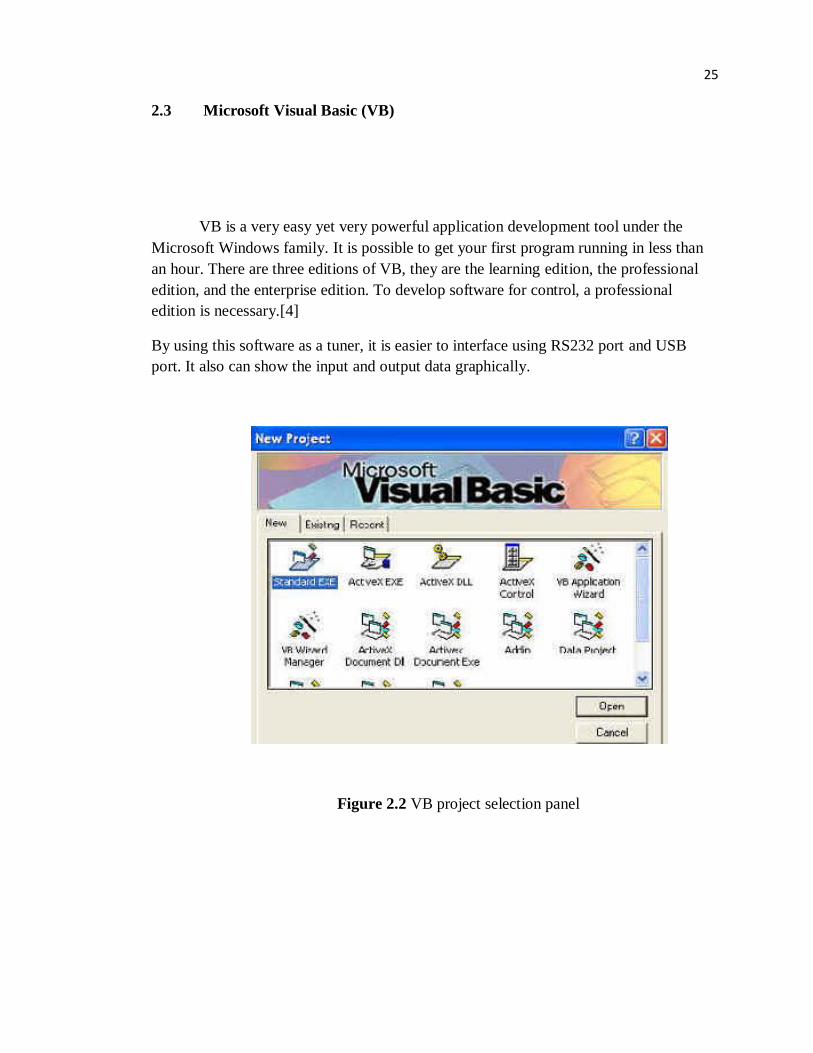
VB is a very easy yet very powerful application development tool under the
Microsoft Windows family. It is possible to get your first program running in less than
an hour. There are three editions of VB, they are the learning edition, the professional
edition, and the enterprise edition. To develop software for control, a professional
edition is necessary.[4]
By using this software as a tuner, it is easier to interface using RS232 port and USB
port. It also can show the input and output data graphically.
Figure 2.2 VB project selection panel

26
Figure 2.3 VB development environments
2.4 Data acquisition card
DAQ is an abbreviation for data acquisition. Therefore a DAQ card is a basic A/D
converter coupled with an interface that allows a personal computer to control the
actions of the A/D, as well as to capture the digital output information from the
converter. A DAQ card is designed to plug directly into a personal computer's bus. All
the power required for the A/D converter and associated interface components is
obtained directly from the PC bus.

27
A DAQ card today is more than a simple A/D function on a board. A data acquisition
card can offer measurements of up to 64 channels at a resolution of 16 bits, (one part in
65,536) with data throughput rates up to 20 million samples per second. A data
acquisition card can often include discrete digital bi-directional I/O lines, counter timers,
and D/A converters for outputting analog signals for control applications.
A high-performance DAQ card will work in a very wide range of test and measurement,
and control applications. Combined with powerful software, DAQ cards will turn a
personal computer into powerful measurement system that may be used to automate
experiments, construct product test stands, monitor and control production equipment or
be embedded in products ranging from medical monitoring systems to automobile test
simulators.
A DAQ card converts analog signals into a digital output form, which can be
manipulated with software. Using software in conjunction with a personal computer,
analog data can be displayed, logged, charted, graphed, or stored in memory as needed.
Stored data can later be used and compared with a set of established limits. Control
decisions are made if the stored data is at the limit, above or below the limit. A DAQ
card can make repetitive measurements, for continuous monitoring and controlling.[5]

28
CHAPTER 3
METHODOLOGY
3.1 Introduction
This chapter will explain the methodology used in this project. The methodology
is divided into two parts which is hardware and software. The first part is simulation for
this system by using Matlab software to determine the value of Kp, Ki and Kd. The
range value for PID is determined by using Ziegler Nicholes method.
The second part is to interface the controller with hardware. The controller is using
Microsoft visual basic 6.0 software. Then, the controller need to interface with DAQ
card first. After interfacing success, the system can be implementing to servo motor.
The feedback value can be received from servo motor encoder.
Figure 3.1 shows the flow chart of the project. After finished the first and second part,
this system can be tuned up by using the PID value from simulation.

29
Figure 3.1 Flow chart of the project
Find motor transfer function
Simulation in Matlab
Find PID value using Ziegler Nicholes
Develop Visual Basic
Interface with DAQ card
Implement PID onto VB
Interface with servo motor
Finish

30
The DAQ card is used as an interface within Visual Basic software and servo
motor. It has analog input, digital input, analog output and digital output port. For this
system, only analog input and output port is used. Servo motor is used to show the
output from controller. It also has a decoder which is used to give a feedback voltage to
the controller. This servo motor input voltage is 5V to 80V.
feedback
Figure 3.2 Block diagram of PID controller
Figure 3.2 shows the block diagram of PID controller. The controller software is
Microsoft Visual Basic 6.0. The PID system is implement in this software where user
can tune the value of Kp, Ki and Kd manually. The value of feedback voltage and error
value shows in this software.
DAQ card
Visual
Basic
Servo
motor

31
3.2 Hardware Development
Before starting develop the hardware, the value of P,PI,PD and PID need to
determine first. It is determine using Ziegler Nicholes method. This value is very
important because it will be used as a reference value to tune dc motor using visual
basic software. Figure 3.3 shows Ziegler Nicholes table;
Controller Kp Ki Kd
PID Kpt [0.1 0.5]
Kp max
Kit [0.1 10]
Kp max Tosc
Kdt [0.05 1]
Kp max Tosc
PD Kpt [0.1 0.5]
Kp max
0 Kdt [0.05 1]
Kp max Tosc
PI Kpt [0.1 0.5]
Kp max
Kit [0.01 1]
Kp max Tosc
0
P Kpt [0.05 0.5]
Kp max
0 0
Tosc value: 0.037s
Kp max value: 1400
Figure 3.3 Ziegler Nicholes table

32
The Tosc and Kp max value is fixed for this dc motor model [6]. Figure 3.4 shows the
result of Ziegler Nicholes range value;
Controller Kp Ki Kd
PID 140 - 700 5.18 - 518 2.59 – 51.8
PD 140 - 700 0 2.59 – 51.8
PI 140 - 700 0.518 – 51.8 0
P 70 - 700 0 0
Figure 3.4 Ziegler Nicholes range value
The hardware is used after the PID value determined. The hardware used is dc
motor and daq card.
33
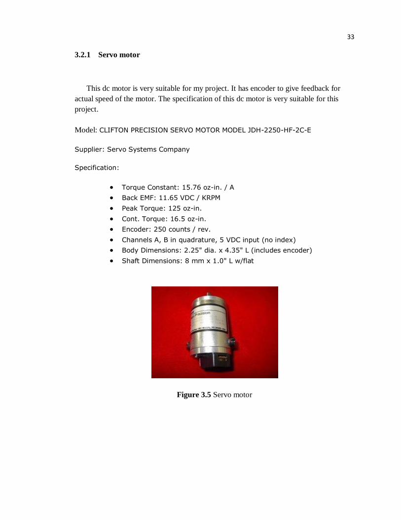
3.2.1 Servo motor
This dc motor is very suitable for my project. It has encoder to give feedback for
actual speed of the motor. The specification of this dc motor is very suitable for this
project.
Model: CLIFTON PRECISION SERVO MOTOR MODEL JDH-2250-HF-2C-E
Supplier: Servo Systems Company
Specification:
Torque Constant: 15.76 oz-in. / A
Back EMF: 11.65 VDC / KRPM
Peak Torque: 125 oz-in.
Cont. Torque: 16.5 oz-in.
Encoder: 250 counts / rev.
Channels A, B in quadrature, 5 VDC input (no index)
Body Dimensions: 2.25" dia. x 4.35" L (includes encoder)
Shaft Dimensions: 8 mm x 1.0" L w/flat
Figure 3.5 Servo motor

34
3.2.2 Modeling DC Servo Motor
The first step of this project is modeling the DC servo motor. Motor modeling is
required in order to obtain the transfer function of the motor which is providing the open
loop system of this project. Then PID controller is adding to changing the system to
closed loop system. Below is the step of the motor modeling.
R= 2.7 Ω
L= 0.004 H
K=0.105 Vs rad-1
K= 0.105 Nm A-1
J= 0.0001 Kg m2
B= 0.0000093 Nms rad-1
araa V
LL
Ki
L
R
dt
di 1 (3.1)
rar
J
Bi
J
K
dt
d
(3.2)
a
r
a
r
a
VLi
J
B
J
K
L
K
L
R
dt
d
dt
di
0
1
(3.3)

35
a
r
aV
iy 010
(3.4)
a
r
a
r
a
Vi
dt
d
dt
di
0
004.0
1
0001.0
0000093.0
0001.0
105.0
004.0
105.0
004.0
7.2
093.01050
25.26675A
0
250B
10C 0D
093.01050
25.26675
0
0
s
sAsI
093.01050
25.26675
s
s
From )(
)(1
AsIdef
AsIadjAsI
(3.5)
If
ac
bd
bcadA
dc
baA
11; (3.6)
ad-bc = (s-675)(s+0.093)-(26.25)(1050)
= s2 + 0.093s – 675s + 62.775 + 27562.5
= s2 + 675.093s + 27625.275

36
6751050
25.26093.0
27625.275 675.093s s
12
1
s
sAsI
27625.275 675.093s s
6751050
25.26093.0
2
s
s
(3.7)
27625.275 675.093s s
262500
)(
)()(
2
sU
sYsT
27625.275 675.093s s
262500
00
250
27625.275 675.093s s
6751050
25.26093.0
10
)(
)()(
2
2
1
s
s
DBAsICsU
sYsT

37
3.2.3 DAQ card
This is the best DAQ card that can support Microsoft Visual Basic software. This
DAQ card use USB port to interface within pc and dc motor. The specification is;
Model: USB 4716
Supplier: Advantech Co. Ltd.
Main Features:
Supports USB 2.0
Portable
Bus-powered
16 analog input channels
16-bit resolution AI
Sampling rate up to 200 kS/s
8DI/8DO, 2 AO and 1 32-bit counter
Wiring terminal on modules
Suitable for DIN-rail mounting
Lockable USB cable for rigid connection
Figure 3.6 USB DAQ card

38
3.3 Software Development
3.3.1 Matlab
Before run the VB programming, a simulation of controller using Ziegler Nicholes
value and Matlab software. With this simulation, we can determine the best value for
Kp, Ki and Kd.
3.3.2 Microsoft Visual Basic 6.0
There are many methods to implement into PID controller such as speed, angular
and acceleration. This controller only measure speed (RPM) by using Microsoft Visual
Basic 6.0 edition as a tuner.
Microsoft Visual Basic 6.0 is an object-oriented computer language that can be viewed
as an evolution of Microsoft's Visual Basic (VB) implemented on the Microsoft .NET
framework. Its introduction has been controversial, as significant changes were made
that broke backward compatibility with older versions and caused a rift within the
developer community.
VB Advantage is a powerful VB development productivity utility that enhances VB's
design time environment. VB Advantage has many powerful, helpful, and easy-to-use
features and tools that were conceived to support software engineering development
activities that developers do as they create and test application code.
Like the BASIC programming language, Visual Basic was designed to be easy to learn
and use. The language not only allows programmers to create simple GUI applications,
but can also develop complex applications. Programming in VB is a combination of
visually arranging components or controls on a form, specifying attributes and actions of
those components, and writing additional lines of code for more functionality. Since
default attributes and actions are defined for the components, a simple program can be

39
created without the programmer having to write many lines of code. Performance
problems were experienced by earlier versions, but with faster computers and native
code compilation this has become less of an issue.
Although programs can be compiled into native code executables from version 5
onwards, they still require the presence of runtime libraries of approximately 2 MB in
size. This runtime is included by default in Windows 2000 and later, but for earlier
versions of Windows or Windows Vista, it must be distributed together with the
executable.
Forms are created using drag-and-drop techniques. A tool is used to place controls on
the form. Controls have attributes and event handlers associated with them. Default
values are provided when the control is created, but may be changed by the
programmer. Many attribute values can be modified during run time based on user
actions or changes in the environment, providing a dynamic application. For example,
code can be inserted into the form resize event handler to reposition a control so that it
remains centered on the form, expands to fill up the form. By inserting code into the
event handler for a keypress in a text box, the program can automatically translate the
case of the text being entered, or even prevent certain characters from being inserted.
Visual Basic can create executables (EXE files), ActiveX controls, DLL files, but is
primarily used to develop Windows applications and to interface web database systems.
Dialog boxes with less functionality can be used to provide pop-up capabilities.
Controls provide the basic functionality of the application, while programmers can
insert additional logic within the appropriate event handlers. For example, a drop-down
combination box will automatically display its list and allow the user to select any
element. An event handler is called when an item is selected, which can then execute
additional code created by the programmer to perform some action based on which
element was selected, such as populating a related list.
Alternatively, a Visual Basic component can have no user interface, and instead provide
ActiveX objects to other programs using Component Object Model (COM). This allows
for server-side processing or an add-in module.
The language is garbage collected using reference counting, has a large library of utility
objects, and has basic object oriented support. Since the more common components are
included in the default project template, the programmer seldom needs to specify
additional libraries. Unlike many other programming languages, Visual Basic is
generally not case sensitive, although it will transform keywords into a standard case
configuration and force the case of variable names to conform to the case of the entry
within the symbol table entry. String comparisons are case sensitive by default, but can
be made case insensitive if so desired.
The Visual Basic compiler is shared with other Visual Studio languages (C, C++), but
restrictions in the IDE do not allow the creation of some targets (Windows model
DLL's) and threading models.
40
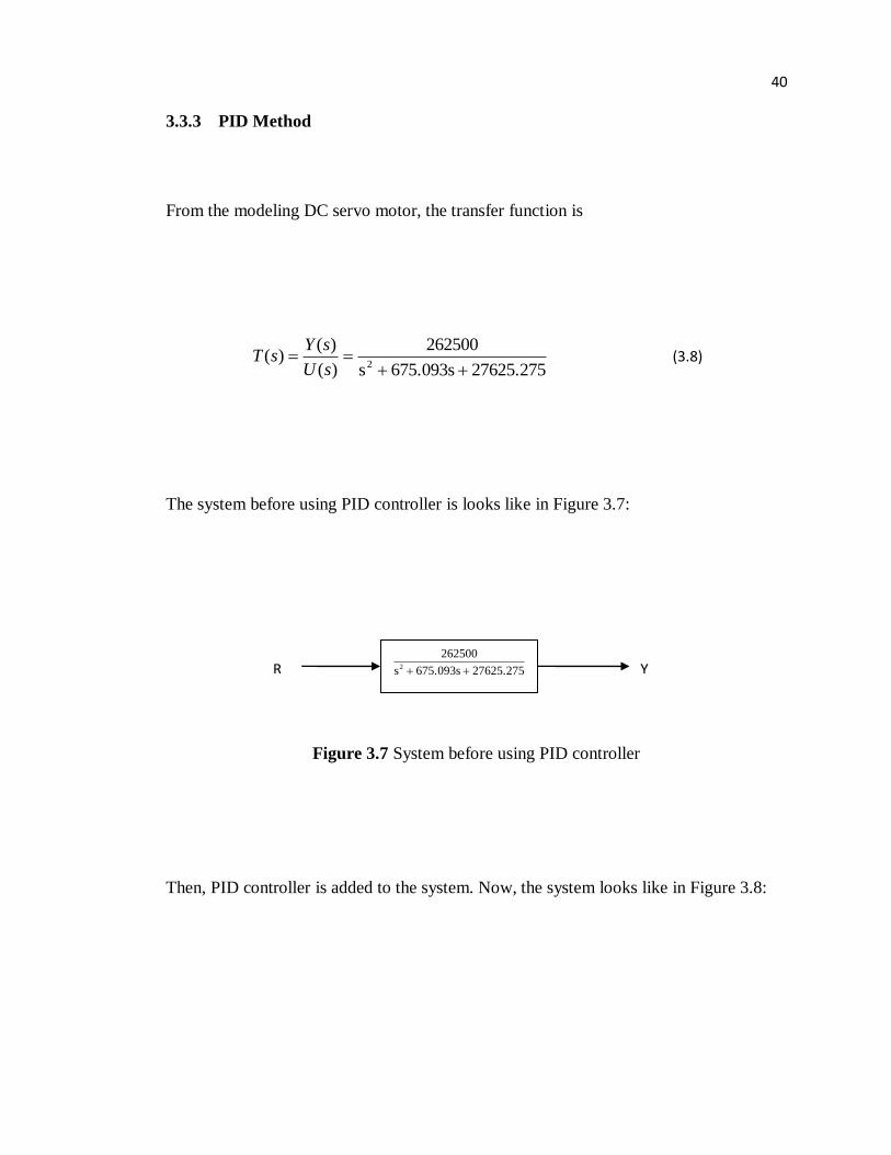
3.3.3 PID Method
From the modeling DC servo motor, the transfer function is
27625.275 675.093s s
262500
)(
)()(
2
sU
sYsT (3.8)
The system before using PID controller is looks like in Figure 3.7:
Figure 3.7 System before using PID controller
Then, PID controller is added to the system. Now, the system looks like in Figure 3.8:
27625.275 675.093s s
2625002
R Y

41
Figure 3.8 System with PID controller
In Figure 3.8, the variable (e) represents the tracking error which is the
difference between the desired input value (R) and the actual output (Y). This error
signal (e) will be sent to the PID controller, and the controller computes both the
derivative and the integral of this error signal. The signal (u) just past the controller is
now equal to the proportional gain (Kp) times the magnitude of the error plus the
integral gain (Ki) times the integral of the error plus the derivative gain (Kd) times the
derivative of the error (equation 3).
The transfer function of the PID controller is:
s
KsKsKsK
s
KK
ipd
di
p
2
(3.9)
PID controller 27625.275 675.093s s
2625002
R Y
e u

42
So, the signal (u) that is past the controller is:
dt
deKdedtKeKU ip (3.10)
This signal (u) will be sent to the plant, and the new output (Y) will be obtained.
This new output (Y) will be sent back to the sensor again to find the new error signal
(e). The controller takes this new error signal and computes its derivative and its integral
again. This process goes on and on.
In this project, the PID controller that was added into the system is designed
using m-file in matlab software. (Refer Figure 3.9)
Figure 3.9 Designed using m-file
43
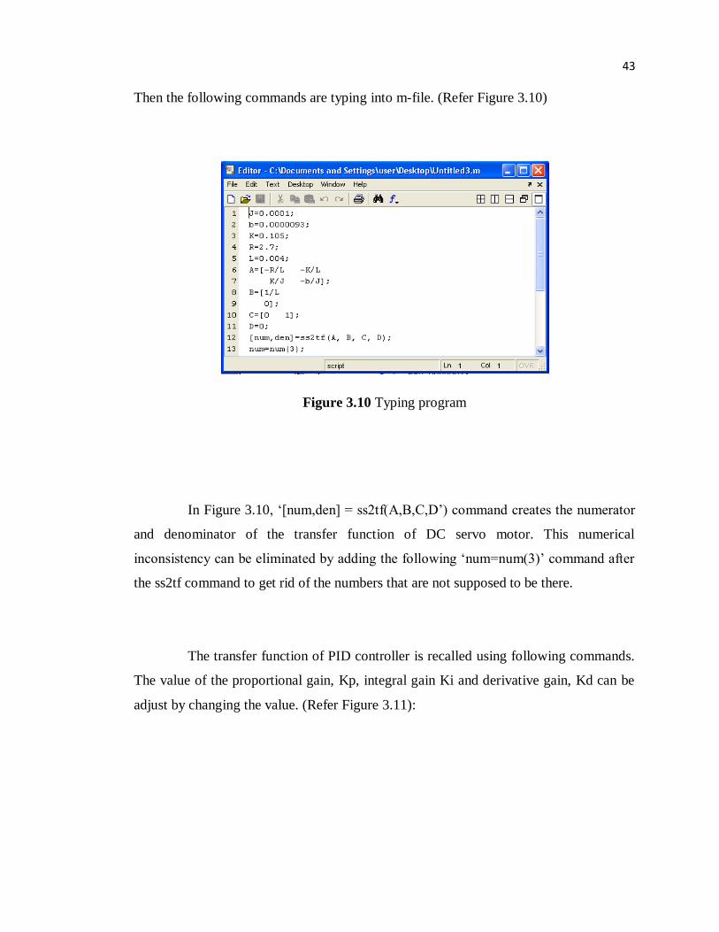
Then the following commands are typing into m-file. (Refer Figure 3.10)
Figure 3.10 Typing program
In Figure 3.10, „[num,den] = ss2tf(A,B,C,D‟) command creates the numerator
and denominator of the transfer function of DC servo motor. This numerical
inconsistency can be eliminated by adding the following „num=num(3)‟ command after
the ss2tf command to get rid of the numbers that are not supposed to be there.
The transfer function of PID controller is recalled using following commands.
The value of the proportional gain, Kp, integral gain Ki and derivative gain, Kd can be
adjust by changing the value. (Refer Figure 3.11):


