
TLCH4NICAL RC POHd -; /-9
PWNETRATION THEORY/4
PENE-TRA I]ON THEORY 1:OR SHALLOW TOMODERATE DEPTHS
Rober> S. Bernardi, Sathya V. 1-Ianagud
Soils and Pavements Laboratory1.. S. Armny Enginoer Witerwaysi Experiment Station
~0. 3~ox 631, Vicksburg, Mis 39180
Juno 1975
Report I f a Serie5i
Aprvdror Public Neat,: Ditribution nli~,mited
0rae' ~fico,, Chief of Engineers, U. S. ArmyW"Ishington, D. C. 20314
lidl Proiect 4AI611r21352E, Task 04,Wei&~ Uni; 013
LIE-stroy this report whent no longer needed. Do not returnit to theo originator.

UncssifiedSSCURITYCLASUFICATIO .OF'THIS PAGIE,(Wi'isaDO'as nftrveD,,-
REPORT ~ ~ ~ ~ ~ ZA INSTRTUCTGEIONS"_________
*PNTNW2. GOVT'ACC ESSION NO. S. 11ECIPIENT'S CATALOG 14UMBER
Technical e6S. TYPE OF REPORT APERIOD COVERED-
VE0P T9FARJETLE EETATO 2 0 Report I of a Series,
CDE C PERFORMING ONG. REPORT NUMBER
T-__XTffW. CONTRACT OR,GRANT NUN3ER(s)
Robert S.A radSathya V/Managud
U.,S. Armxy Engineer Waterways Mxperiment, Station'Soils and Pavements Laboratory Proj ect 'WA6liO252E,P. 0. Box 63i. Vicksburg, Miss. 39180 Taski o4, Work 71nit 0V1
11. CONTROLLING IOFFICE NAkItE A ND ADURESS -
Office,, Chief of Engineers, U. S. Army / ~ '7
-1 1 1 N ile*c) Is. SECURITYCLASS. (of this -part)
Unclassified
1,13a, OECLASSIFICATION/OOWNGRADING
IS. SUPPLEMENTARY NOTES
13. KEY WORDS (Continuo on r-eves, side It necessary s~d Identify by block numb.,)
Projectile penetration
ABSTRACT (Continua on tee.,,, aide It necessery and Identify by block numb*?r)
Previous work in penetration theory, based on the theory for dynamic expansionof a spherical cavrity in a compressible strain-hardening medium, is extendedto Include the effects of nose shape, layered targets, and oblique impact.Parametric implications of the theory are investigated, and governing paran-eters are defined. Theoretical results are compared with experimental andempirical results and with two-dimensional finite-difference solutions; good
agreement is obtained when the penetration resistance of the target due toshear Is cornparable with that dIue to inertia.-
DD I J3AN73 1473 EDITION OP~ I NOV 65 IS OUSOLETE 1\ Ucasfe
SECURITV CL kSSIFICATION OF THIS PAGE (noen Data Enteted)/

gCUINTY'CLAMPIATIOU Of' THIS PAGUnwo m te "foWO-O.Uclsife II
k UnclassifiedSECUflITY CIASSIFICATION OF THIS PAGE(Wh7.' Data Entetod)

1 PREFACE
the investigation reported herein was conducted by personnel of
the Soils and Pavements Laboratory (S&PL), U. S. Army Engineer Waterways
Experiment Station (WES),. as a part of DA Project No. 4A161102B52E,
"Fragment and Projectile Penetration Resistance of Soils," Task 04, Work
Unit 013.
The research was accomplished by Mr. R. S. Bernard (WES) and
Professor S. V. Hanagud, Georgia Institute of Technology, during the
period July 1973 to June 1974 under the supervision of Dr. J. G.Jackson, Jr., Chief of the Soil Dyna ics Division, S&PL. Messrs. J. P.
Sale and R. G. Ahlvin were Chief and Assistant Chief, S&PL, respec-
tively. SP4 D. C. Creighton executed the necessary computer calcula-
tions, and Dr. B. Rohani provided continuing support through his famil-
iarity with previous work in this area. This report was prepared by
Mr. Bernard and Professor Hanagud.
BG E. D. Peixotto, CE, and COL G. H. Hilt, CE, were Directors of
WES during this investigation and the preparation of the report.
Mr. F. 'R. Brown was Technical Director.
1iit- *Jr
"-fJ - ' '.P '-S '*.0A"0".
,~0 CONTENTS
I'REFACE * * . . . . .. .. . . . . . .1L" CONVERSIONIFACR U..,S. CUSTOMARY'TO METRIC (SI)UNITS OF MEASURI1ENT .. . . .. . . . '14
PART I: INTRODUCTIN T ...... . . . .. . . . . . 5Background .. .. .. . .... .. . .. .. .. ... 5Purpose . . . . .. . . . . . . . .... .. 6,
PART, II: PENETRATION THEORY . . . . . . . 8.
Historical .ckgroun .. . . ...... . . .. 8 ..Cavity Expansion Theory . . .. . . . .... . 8'Penetration Theory for Spherical Projectiles ... . . 9Penetration Theory for Axisymetric Projectiles- . .. . 1Penetration Theory ft6 Layered Targets..... .........Obi Impact Theory . eo.. ................. . 28j< ,PART III: SOME PARAMETRIC IMPLICATIONS OF PENETRATION THEORY.. 37
The Nondimensional 'Equation ofMotion ......... . . 37The Shape of the Deceleration Curve ... o . . . .. 0The Relative Effects of Nose Shape and Frontal Loading onFinal Depth of Penetration . . . . . . ....... 42
Parametric Differences Between Theoretical and'Empirical Results for Homogeneous Targets-. ...... . 45
Penetration of Layered Targets . ............. .46
PART IV: APPLICATIONS OF PENETRATION THEORY . • . ....... • 47
Introduction...... . ... . . . ......... . 47Choice of Material Properties .............. . 47Penetration of Rock ................... .. 48Penetration of Concrete .................. 51Penetration ofSoft Earth........ ....... . 53Perforation of ,a Metal Slab ............. .... 54Oblique Impact Against Hard Earth....... . . . . . . 60
PART V: CONCLUSIONS AND RECOMMENDATIONS . .......... 63
REFERENCES . . . . . . ............... ........ 65
-. APPENDIX A: SPHERICAL CAVITY' EXPANSION IN A CONCENTRICALLYLAYERED -MEDIUM . .......... .. . . ... . . . Al
Introduction . .............. . . . . . . . AlProblem Formulation ....................... AlInertial Terms ................... AShear Terms . . . . . . . .. . A8Relations Among ajt, bjt) and h(t) ..... . . A12Combined Effects ...................... A14
1 2

co'm s
* CONTENTLS
Sumay of* Results . . . A16Special Cases ................... . .. . . Ai8
APPENDIX B: COMPRESSIBILITY . . . . . .. . . . .. . . B1
Introduction .................. . . B1Average Dynamic Pressure in the Plastic Zone. ...... . .... BComp#-ssibilityr in the Penetration Theory . ....... ... B3
APPENDIX C: TARGET ACCELERATION ....... . ......... Cl
Introduction ....... ......... . ClThe Effect of Added Mass on Penetration Predictions .... Cl
APPENDIX D: NOTATION . .................. . . . Dl
5]

CONVE2 SIONi F'ACTORS, U. 'S. 6USTOMARY TO MMI'IC (SI)
V NITS OF ?EASURDENT
U.i S., customary units. of measuremenzt used in t-4his report ,canbec-
verted to metric (SI)' units as-folloiis:.
Multiply'Bz To.'ObtAin
inches 2.54 cenitimetres
feet 0.30o48 metres
'pouknds (mase) 0.14535924 kilogramsslug-square feet 1.353 kilogram-square metres,
rpounds (mass) per cubic foot 16.018146 -kilograms- per cubic metre
slugs per cubic toot 515.3788, kilogr,,w.. per cubic metre
pounds (korce) per square inch 68914.75T pascals
kips (force),,per square inch 68914.757 kilopascalg
feet per second 0.30o48 metres per second
degrees (angle) 0.01714539 radians
Note: 1 kbar =1,000 bars = 14,500 pounds per square inch-100 megapascals.1 slug =32.2 pounds (mass).
14 -

DEVLOPENTOF A PROJECTILE PENETRATION THEORY
PENETRATION THEORY FOR SHALLOW TO MODERATE DEPTHS
PART I,: INTRODUCTION
Background
1. The phenomenon of projectile penetration has been the object
of numerous analytical and experimental investigations over the past
two centuries.1 Until recent years, successful analyses were of an em-
pirical or' semiempirical nature, utilizing various target resistance
functions and pseudoconstants which were inevitably drawn directly from
penetration experiments. As a result, the subject of penetration re-
[ mained isolated from the rest o >mechanics because the relation between
target constitutive properties and penetration resistance was unknown.
Nevertheless, a number oIV useful empirical equations were developed
which afforded reasonable, stimates of penetration depth for a varietyof situations. Unfortunately, the reliability of such equations is
limited to the range of test conditions for which they were deduced, and
the accuracy of prediction may dwindle significantly with extrapolation
to situations which have not been characterized experimentally.
2. The last decade has given rise to a more basic approach to
penetration through the use of digital computers. In various efforts,
the details of target and projectile motion have been analyzed by means
of two-dimensional finite-difference techniques employing realistic con-
5-7stitutive properties for both target and projectile.5 While a finite-difference solution may achieve good agreement with experimental observa-
tion, as shown in Reference 7, its execution is cumbersome and costly,
thus diminishing its utility as a practical engineering tool. However,
this approach represents a powerful device for examining the details of
target and projectile behavior, indicating the relative consequences of
different simplifying assumptions, and providing a means of determining
what mechanisms are most important in the projectile-target interaction.U 5

3. At the present time, #L is a growing need for a simple
/ theory which affords reliable analyses of the impact and penetration of
rigid projectiles such as missiles, bombs, 'bullets, shel fragnents,
artillery and mortar rounds, and air-delivered mines and sensors intotargets such as Soil, r~ck,.concrete, and metal. Ther esults Of theseanalyses could be used in design and optimization, both from the offen-
sive 6,h defensive points of view. In July 1973,,a small research ef-
'fort was initiated under the sponsorship of the Office, Chief of, Engi-
neers,, to develop a, tractable projectile penetration theory for natural
and artificial earth targets. The general r~quirements were that the
Ktheory should'account for the penetration of homogeneous and layered-targets by rigid'projectiles of various nose shapes and should deal at
least approximatelywith oblique impact. Further, the theory should be
derived from a consideration. of target constitutive properties without
recourse to penetration tests per se. The objective was to replace,
neither-empirical nor finite-differenceanalyses, but rather to provide
a practical tool for making reasonable predictions before the execution
of a penetration test or finite-difference calculation. The develop-
ments presented in this report are the re3ult of efforts conducted under
this program during the period July 1973 to June 1974. Report 2 will
document the extension of the present theory for application to very
deep penetration in homogeneous and layered targets.
Purpose
4. The purpose of this investigation is to build upon existing
penetration theory8 - 12 to develop an approximate but more general theory
meeting, the requirements stated above. The starting point for the pres-
ent work -is the so-called "'cavity expansion theory," originally applied
to projectile penetration by Goodier.9'1 0
scope
5. Part II of this report outlines modifications of previous8-12
theoretical work in 'which the effects of different nose shapes,
6

layered targets, and oblique impact are incorporated into a penetration
theory for rigid projectiles. In Part III, the modified theory is non-
dimensionalized, governing parameters are determined, and results of
parameter studies are presented. Part IV contains comparisons of theo-
retical results with experimental observations and two-dimensional
finite-difference solutions. Part V presents the conclusions and recom-
mendations. The theory of dynamic expansion of a spherical cavity in a
concentrically layered medium is developed in Appendix A. A discussion
of material compressibility as it relates to the cavity expansion theory
and the penetration theory is contained in Appendix B. The effect of
target acceleration on final penetration depth predictions is investi-
gated in Appendix C.
*-1 1'

( V .. .. . . ' -- ,-*- i
PART II: PENETRATION THEORY
Historical Background
6. The foundation for the present penetration theory was laid by8
Bishop, Hill, and Mott, who applied the theory of spherical cavity ex-
pansion in a strain-hardening medium to penetration by a rigid static
punch. Goodierl0 later extended this work and applied it to the pene-
tration of a strain-hardening target by a high-velocity rigid spherical
12projectile. Hanagud and Ross modified the cavity expansion theory to
account for a compressible medium by means of a locking approximation
and employed the results in Goodier's penetration theory.
Cavity Expansion Theory
7. The theory of dynamic expansion of a spherical cavity sur-
rounded by concentric layers of compressible locking, strain-hardening
material is developed in Appendix A. This cavity expansion theory forms
the basis for the penetration theory discussed in the present report.
The behavior of the material in shear (Figure A2) is characterized by
the compressive yield strength Y , the modulus of elasticity E , and
the strain-hardening modulus E .* The effect of material compressi-Itbility is approximated by means of an instantaneous locking assumption
whereby material in the plastic state is presumed to be compressed to a
uniform (i.e. locked) density p . As discussed in Appendix B, the
instantaneous locked density p, is a function of the instantaneous
average dynamic pressure in the plastic zone.
8. According to Equation A76, the compressive normal stress p
at the cavity surface is
P = P + P(ai + B2 a) p + pI (1)
* For convenience, symbols and unusual abbreviations are listed and de-
fined in the Notation (Appendix D).
The two terms, ps and p, which appear in Equation 1 are the sepa-
rate contributions due to material deformation (shear) and inertia, re-
spectively. Henceforth, the shear contribution ps will be called the
"shear resistance"; and the inertial contribution pI = P Bla + Ba2)
will be called the "dynamic pressure" where a , a , and 9 are the
radial position, velocity, and acceleration of the cavity wall, and B
and B are dimensionless inertial coefficients. For a homogeneous ma-2
terial (i.e. no layering), p 1 B1 , and B2 are identified by Equa-
?. i. tions A87, A88, and A89, respectively. Moreover, these quantities are
functions of Y , E , Et , and the instantaneous locking strain
,. l.n p/p. , where p is the initial density.
Penetration Theory for Spherical Projectiles
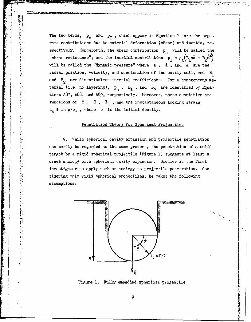
9. While spherical cavity expansion and projectile penetration
* can hardly be regarded as the same process, the penetration of a solid
target by a rigid spherical projectile (Figure 1) suggests at least a
crude analogy with spherical cavity expansion. Goodier is the first
investigator to apply such an analogy to projectile penetration. Con-
sidering only rigid spherical projectiles, he makes the following
assumptions:
* I
S 4,
q !ao =D/ 2
Figure 1. Fully embedded spherical projectile
Lit 9

a. The embedded portion of the projectile frontal surface as
seen in the above figure is in complete contact with the
target.
b. During the embedding process (penetration depth q <
projectile radius a0 ), the projectile-targe- nteraction
is equivalent to a dynamic Brinell hardness test, and the
a al resisting force is given by Meyer's law.9 1 2
c. After the projectile is fully embedded (q > a0 ), only
normal stresses exist on the projectile frontal surface
(i.e., the effect of friction is negligible).
10. At this point, Goodier sets about to modify Equation 1 in
order to approximate the normal stress distribution on the frontal sur-
face of a fully embedded spherical projectile. To this end he makes two
assumptions: (a) the normal stress due to shear (i.e. shear resistance)
is constant over the frontal surface and is identical with ps in Equa-
tion 1; and (b) pl is maximum at the stagnation point 0 = 0 and zero
at the shoulder 0 = w/2 , where 0 is measured as shown in Figure 1.
Identifying a with the cavity radius a , the projectile velocity0
q with the cavity radial velocity a , and the projectile acceleration
with the cavity radial acceleration 9 , Goodier then proposes
pi = Pt(Blaoq + B2q2 ) cos 0 (2)
as a reasonable variation of dynamic pressure over the frontal surface
0 < 0 < n/2 . The compressive normal stress p on the projectile
frontal surface is then
p p + Pt (B1 a + B22 ) Cos 0 (3)
In Goodier's investigation the target is assumed incompressible such
that, pt = p , B1 1 , and B2 = 3/2 . The rationale employed by,' . . . 11,12 2
Hanagud and Ross is identical with that of Goodier except that the
target is considered compressible locking such that p£ > p , B1 < 1
B2 < 3/2, and the value of p5 is less than the incompressible value.
10

11. Integration of Equation 3 over the frontal surface leads to
the following equation of motion for- a projectile of mass :
-7a2[s + -aP,( 1ao + 12j2()]
21 2Equation 4t is rearrangedsc thatP~~a~ B4)](~
(+ -9 ira~p B)i -7ra 2(p + -9 pXB 2 (5),
Equation A88 indicates that B1 1 ; consequently, the effect of target
acceleration is small in Equations 4 and 5 when the added mass 3 for the
sphere is small compared to the projectile mass, i,e., when
2 << M (6)
With the ratio R defined asa[ 3R Ot(7)
Ra
the effect of target acceleration on projectile loading is then small
when Ra << 1 . Moreover, the quantity (213)wa3p B1 probably repre-
sents a high upper limit on the added mass term, and penetration pre-
dictions are improved in some cases by discarding the added mass term
(i.e. the B1 term) altogether, as shown in Appendix C. At any rate,
Goodier's dynamic pressure distribution is adequately approximated by
, - .2 cos R << (8)
12. Although the rationale employed by Goodier leads to fairly
accurate predictions of final penetration depth (Appendix C), the
cos 0 distribution of pI is somewhat arbitrary. Other distribu-
tions of dynamic pressure produce projectile equations of motion iden-
tical to Equations 4 and 5. (For example, this occurs when cos 6 is~i ~replaced by 1 - sin 0 in Equations 2 and 3.) Furthermore, the

projectile equation of motion must be integrated with, respect to time to
obtain the final depth of penetration, so that a "correct" prediction of
final depth alone indicates only that the average resisting force is
correctly predicted. Thus, there is some flexibility in Goodier's
rationale, insofar as the distribution of dynrimic pressure is concerned.
Moreover, it is this flexibility which allows extension of the cavity
expansion analogy to projectiles with nose shapes other than
hemispherical.
Penetration Theory for AxisZmmetric Projectiles
13. Before generalizing the penetration theory to nose shapes
other than hemispherical, it is necessary to reevaluate Goodier's three
basic assumptions. First, the assumption of complete contact between
the target and the embedded portion of the projectile nose (i.e. frontal
surface) is retained. Although this assumption is physically question-
able, it will provide an upper limit on the resisting force, at least
within the framework of the theory. Second, the dynamic Brinell hard-
ness analogy is discarded. Instead, an analogy with the cavity expan-sion theory will be used throughout the penetration process to approxi-
mate the normal stress distribution on the embedded portion of the
projectile nose. (This will produce a higher target resistance during
the embedding process, which will improve penetration depth predictions,
especially for shallow penetration.) Third, friction effects are dis-
regarded at all times on the projectile nose and aft body alike. This
is a questionable assumption, although there is some evidence suggesting
that friction on the aft body is relatively insignificant.
14. Subject to the above assumptions, Equation 1 is now modified
in order to approximate the normal stress distribution on the nose of a
projectile with an arbitrary axisymmetric nose shape. As in Goodier's
rationale, the normal stress due to shear is assumed uniform over the
nose and equal to p5 " This leaves only the distribution pl to be
o' determined as a function of nose shape. The problem, of course, is to
arrive at a single rationale which generalizes the distribution of pl
12
to any axisymetric nose shape in a straightforward, ia*mer. Yurthr-
more, the resulting effect of nose shap e on final penetration depth
should be consistent with experimental observation.
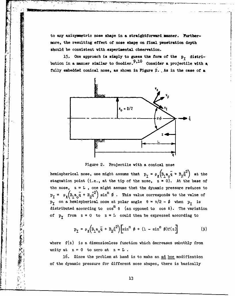
15.. One approach is simply to guess the form of the pI distri-
bution in a-maner similar to Goodier.9 1 0 'Consider a projectile 'ith a
fully embedded conical nose, as shown in Figure 2., As in the case of a
I,
F4 Figure 2. Projectile with a conical nose
)hemispherical nose, one might assume that pi = pt(Blaoi + B 2) at the
stagnation point (i.e., at the tip of the nose, z = 0). At the base of
the nose, z = L , one might assume that the dynamic pressure reduces to: iPl = P£( 1 a~q + B2q.2) sinn 0 " This value correspondsto the value ofSP1 on a hemispherical nose at polar angle = 1t/2 - 0 when p1 is
'K distributed according to cosn e (as. opposed to cos 0). The variation
of pI from z =0 to z = L could then be expressed according to
-<I0
'P = PL(Blao + Bnn0 + (i - sinn )e (9)
where f(z) is a dimensionless function which decreases sifoothly fromunityat z=0 to zero at z = L .
t a 16. Since the problem at hand is to make an ad hoc modification
of the dynamic pressure for different nose shapes, there is basically
, - 13

nothing wrong with the approach outlined above. On the other hand, the
aritrariness in the development Of Equation 9 prompts one to seek a
more fumdamental scheme based (albeit crudely ) on the underlying physics.
The fact that the dynamic pressure which appears in Equation 1 depends
on both particle acceleration aid velocity suggests that the pI dis-
tribution for an axisy~metric projectile can be obtained by approxi-
mating the variation of particle acceleration and velocity along the sur-
face of the nose. Moreover, since most cases of practical interestsatisfy the condition Ra << 1 , the particle acceleration has only a
small effect on projectile loading, and it is then sufficient to ap-
proximate the variation of particle velocity alone.
17. In order to construct a reasonable distribution of particle
velocity v on the nose surface, one must first consider certainp
physical constraints on particle motion:
a. A particle at the very tip of the nose (i.e. the stagna-
tion point) must move with the projectile velocity .
b. The component of particle velocity v normal to the
surface of the nose must be equal to the normal component
of projectile velocity (i.e., material cannot cross the
target/projectile interface).
c. Over the nose surface v must be continuous.-- pd. Finally, it is assumed that the tangential component of
particle velocity vt is zero at the base of the nose.
Relative to these constraints, only the variation of vt along the
length of the nose remains to be specified. Although it is quite pos-
sible that vt is a complicated function of target properties, projec-
tile velocity, nose shape, and relative position on the nose, the pres-
ent investigation considers only the effects of nose shape and relative
position.
18. Consider first the fully embedded conical nose shown in
Figure 2. The normal component of velocity v is given by
n
v 4 sin (lO)

where 0 is the cone -hbi-anjle., Nci efining
where iz is 'longitudiial distance from the nose tip and L is noje
length, the following equation. is., I)bosed for {
Vt ( - x)112 cos, € , o<x<1 '(12)
The ,resulting expression for v is thenp
1/2 1I~ /2=v * / 2) x coo (113)
2'I'
Le(&) .
a : D/2 : a@
27'
Figure 3. Projectile with an ogival nose
19. Consider next the fully embedded ogival nose shown in Fig-
ure 3. The normal component v is given by
15

- V '.j~sin -(i)
n -
vtuhere is the half-angle- for the circumscribed cone vhich, is tangent
to the ogive At any !ongitxidina1 position z . To Arrive at a func-F tional fors for v which is consistent with- Equation 12, the effectivecone length L-(*) and effective longitudinal position. ze(*) (Fig-
ure 3) are defined by
) U- cos 0. o ) (15)
and
z () a(*, ct 4,(16)
where
a(*) = R(cos 4 - cos (17)
anda = ( -cos 0) (18)
The effective dimensionless cone position xe ) is then defined as
Xz ) e cos J(cos 4-cos0) (19)e'() -" ,e 1 - cos 'cos"*
In order to be consistent with Equation 12, vt is taken to be
ThstVt= 4 - xe(4 )1/2 CoBs (20)
SThus, the expression-for Vp. is
v + 2) = - x() cos2 1/] (21)
20. By replacing a by % a by v , and by in
Equation 1, the general expression for p. on an axisymmetric nose sur-
- face is

pj,- Ba q + p B v PB 2vp-, R <<1 (22)
where v is ,given by Equa.tions 13, and 21 for. cones and ogives, respec-
tively. T#us,
PI 2 PB 2( - x cos2 )2 for ,cones (23)
and
(2-.PI2 01 - 'e( Cos 2 'q-4 for ogives (214)
when R < I . For a hemispherical nose, which is the limiting case
for-an, Oive, Equation 24 reduces to
Pi - - cos4 Vi) " P,B22 (1 - sink 4) (25)
where 60= w/2 - * as indicated in Figure 1. A comparison of EquA-
tions 8, and 25 is presented in ,Figure 4 to show that for a hemispherical
LEGEND
-,_ GOODIER 9 . 10 EQUATION 8
PRESENT WORK, EQUATION 25
0 I
0 rn/4 r
POLAR ANGLE 0
Figure ).Graphic comparison of Equations 8 and 25 for distributionof dynamic pressure on a hemispherical nose
o 17
A
nose the P distribution obtained by assuming a functional form for
v% is not rad ically different from Goodier t s assumed pI distribution.
21. With the normal stress distribution having been approximated
for conical and ogival noses (the ratiouale outlined in,,paragraphs 1T-20
can be readiY applied to other axisyrmetric nose shapes), the next step
1 is to. obtain the resulting projectile equations, of motion. This in-
volvos integrating the normal stress over the surface of the nose to ob-
tain the total axial resisting torce 'F acting on the project le.z
Thus, for projectiles with conical noses, Equations 11, 13, and 22 are
substituted into Equation 1 and integrated over the surface of the nose
to. obtain
zLt
Mq = -f [p. + p1(z,0)sin 0 dA (z-)z (26)
Z=0
where
dA (z-, 0) =2wr--, dan (27)
cos 7 dz
Likewise, for projectiles with ogival noses, Equations 19, -21, and 22 are
substituted into Equation 1 and integrated over the surface of the nose
to :obtain
Mq = -F = -f + pl(0) sin * dA (1) (28)
where
dA (.) = 2w tan z() dze (q) (29)cos'4i e e
The resulting projectile equations of motion have the form
M 3 "P'B =-r '(p + pBLf (30)
V 18

, The quantity fn (nose shape factor) results from the variation of pl
over the nose and thus characterizes the relative effect of nose shape,
on the average inertial resistance of the target to penetration. For
conical noses of length L and base diameter D : 2a shown in Fig-0Jure 2,. f is expressed a6
f =1--31
F where
L (-32)
For ogival noses of length L and base diameter D iilustrated in Fig-
ure 3, f is written as
fn =1-2 2 6 [P2 1n (2-c)-- (B 2 + 2 ])( - (3)
+ 1 (3B3 + 6B-+ 1)(B 2 ) - 2L (B' - c)
-1 (t + 6B + 3)(B3 - 3) + 1 (2B + 3)(B 4 - (33)
where
B- 2c c 2 (34)
2 (35)
hC 2 + I
and g = L/D . For ogives, the relation between the caliber radius head
(CRH) and ? is
CR11RH (36)
4- An ogive with = 1/2 is a hemisphere, for which case Equation 33 re-
duces to f = 2/3 and the right hand side of Equation 30 is identicaln
19__

with Equation 5. Thus, for spherical-projectiles and projectiles-with
hemispherical nose shapes, the distribution of particle velocity given
by Equation 21 leads to essentially the same equation of ,motion as thatobtained by and by Hanagud and Ross when R << 1.
22. Whether one chooses to develop projectile equations of motion
based on assumed stress distributions or assumed particle velocity dis-
tributions is of little consequence in the final analysis. The impor-
tant question is whether or not the equation of motion (30) leads to
reliable predictions of final penetration depth for projectiles with
different nose shapes. Moreover, the relative effect of nose shape on
final penetration depth should lie within experimentally observed bounds.
(For earth penetration, variation of nose shape from a blunt cylinder to
a sharp cone seldom increases final penetration depth by more than -a
factor of three. 2) Thus, the choice of a velocity or stress "distribu-
tion leading to f is neither arbitrary nor unique, and it is no acci-n
dent that variation of nose shape from a blunt cylinder to a sharp cone
reduces target inertial resistance in Equation 30 by no more than a fac-
tor of three. The tangential velocity distribution given by Equation 12
is chosen so as to produce precisely this effect.
23. While fn is presumed to characterize the relative effect ofn
nose shape on inertial resistance to penetration for a fully embedded
nose, the embedding process itself must also be considered in order to
determine the overall effect of nose shape on penetration depth, espe-
cially for shallow penetration. Assuming that fn approximately char-
acterizes inertial resistance during the embedding of the nose, the
equation of motion during the. embedding process is
[P + Ird3q)p~B wa 2(q)[P + P B f2] ,q :j ZBL7 Bf (37)
where an(q) is the cylindrical radius of the nose at the surface of2the target, and 7a n(q) is the frontal area of the projectile which is
in contact with the target for a given penetration depth q <L , as
shown in Figure 5. When q > L , Equation 37 is replaced by Equation 30.
20~' 1I:"'

ao0 D/2, an(q)! I.
q;
'Figure 5. Projectile with partially embedded nose
A study of the relative effect of nose shape on final penetration depth
is given in Part III.
Penetration Theory for Layered Targets
24. The penetration theory for larered targets is based upon the
cavity expansion theory for a concentrically layered medium presented in
Appendix A. The physical situation to be considered is illustrated in
Figure 6. As is the casein Appendix A, the investigation is restricted
to the two-layer situation. Physically, this means that a target may
have any number of layers so long as the projectile equation of motion
is significantly influenced by no more than two layers at a time.
25. The projectile equation of motion is assumed to have the
same form as that for a homogeneous target, Equation 30. However, ap-
proximations for ps , BI , and B2 must be obtained through an appro-
I ~ priate analogy with the cavity expansion theory for a concentrically
layered medium. The point which becomes the point of maximum deforma-
tion on the layer interface is denoted by H(t) and coincides with the
projectile axis of symmetry (Figure 6). The initial distance from the
21

LAYER 1 LAYER 2
TARGET SURFACE
INTERFACE
____H-q+/
ao
i P.
H (t)
Figure 6. Penetrabion of a layered target
target surface to the layer interface is H- . A first approximation°
(probably representing an upper limit) to the effective deformation of
the layer interface is then obtained by replacing the penetrating pro-
jectile with a spherical cavity of radius a and radial velocity
located at the base of the projectile nose (i.e., at depth q L)
and assuming that the motion of the point H(t) is the same as that
of a point lying on a spherical surface of instantaneous effective
radius H - q + L and effective radial velocity H , concentric to
can be determined in the same way, where S - q + L is the instanta-
neous effective radius of tke front and S is its effective radial
velocity. First approximations to p B and B2 are then
222

obtained by substituting a for a(t) , q for a , H - q + L for
* h° , H- q + L for h(t), H for h, S - q + L for b(t) , and
S for b in Equations A79-A84.
26. In direct analogy with Appendix A, H a H for S < H ,0' 0
i.e., the deformation of the interface is assumed negligible prior to
the arrival of the plastic front. From Equation A57, S - q + L is re-
lated to a by0
aS q + L 1/3 S < H ( 38)
1
where 6 is given by Equation A53. The condition S < H is now re-1 -0
placed by q _ q* where
aq* = + L- 0- (39)
°1
which represents projectile penetration depth when the plastic frontreaches the layer interface. Equation 39 is structured so that S = H
0when q = q, . When q _ q* , the projectile equation of motion is
r P (i) "' a2[p(l) + p B(l)f 2 q < q, (ho)
[M+ ia jq = P 10 s 2n
where, with the exception of B(l) and B(l) , the subscripts 1 and1 2
2 denote first and second layer properties, and
(1) 2 ~ 4nl
i~~~ p0I ) _l 22 YIi i + 9 E I 2-0
IIal(Ho q + L) 6l(Ho q + L.)
23

Ia
1 H q
K ad - 2and
2- - 2/3 2 1
4 -A
.2 r 1 ]-- (1-, , 4 (HP:J (43)2 ) (H° - q + i)
where 6 , 8 , and o are defined by Equations A90, A91, and A93, re-
spectively. Equations 41-43 are analogous to Equations A79-A81.
27. After the plastic front has reached the interface, the pro-
jectile equation of motion is
3 2[*)M + ra p qB -a P( + , * q > q* (441)
where, with the exceptions of B and B , the subscripts I and
2 denote first and second layer material properties, qnd
(*p =2Y ln + 4 0
s 1 a + 0" Et 2 - q + L
+ 2Y 1nS-q+L+0 2[S +L3
2 "
+~ 02E2 (45)
214

S -z H- q + I + - - "" + 12s-q ;,, (6
+* 2 ) H1 -q)_ L 2 S I )
. +. .21=l" S qq+
- 2)
+i A an s 2(i - +
I-.,~~2 \10 L' n or bte
2 q + L11 _2
0 ()H q' + L 2 (I+)(i
fo bad franhe2 2
0q' + L)2 o
(S - q
* - 25
E 4 a
tion A6, ad sbstiutig H- q+ L or fo S +for and9 fo the

1 1'Equations 49 and 50 give only crude (and probably upper limit) approxi-
mations to the effective positions of the layer interface H and the
plastic front S as the projectile approaches the interface. Moreover,
Equation 50 is reasonable only when 61 < 61 , i.e., when the distance21
S -,q + L increases to the final value a /61/3 as the projectile en-
ters the second layer. On the other hand, when 6 > 6 , the distance
S -q + L decreases to the final value a n which case S
is simply located at H until S- q+L= ao/6
28. The approximations engendered by placing, the effective cavity,
'(A = a0 ) at the base of the nose require some modification when q > H
ie., when the nose extends beyond the effective interface depth H , as
illustrated in Figure 7.
-- EFFECTIVE INTERFACELOCATION, H (t)
ao D/2 r ,O10)
I-I
Figure 7. Situation when q > H
2In such a situation, the frontal area in contact with layer 2 is zaH Hand the frontal area in contact with layer 1 is w a 2 ao ) The
projectile equation of motion then becomes approximately
"26°" ';2 6

IM'for q > H ,where
(**) (1) , (2) a
)a2 2B2 - () P. 2 q < q, (514)
Sand
0) 0
B1k 1 3 q (56)
27pa 2 (2) a.
:B2 B2 - - + - 2 B -2 q < q * (54)a 1 ai 0o
2 2{< ~ ~~~ ~~ +h quniie-p2 (2)2 N 9n B 2) are (55)rsstnen
aH. pt. 2 (2
B *(6
2 2(2) ln6 + 2+ (58)p -
B (2) 1-
29. When the projectile nose becomes essentially embedded in the
second layer, i.e., when H - q + L-= a ° , the equation of motiorn is
approximately
[M+ 1 (29)B1 2 2
2 J o
at a -H-q+L (61)
': "which is the same as for a homogeneous semi-infinite target having the
30. When q < L , i.e., when the nose is not fully embedded in
the first layer of the target, Equations 38-61 still apply except that
a ° is replaced by a n and L is replaced by q (Figure 5).
Oblique Impact Theory,
, 31. The investigation thus far has disregarded projectile rota-tion which may occur due to oblique incidence with the target. Conse-
quently, the next step involves a projectile with a conical nose of half-
angle 0 which strikes the target with an initial angle of obliquity
, as illustrated in Figure 8 The X,Y,Z right-hand, orthogonal
coordinate system is fixed at the point of impact on the surface of the
target. Figure 9 shows the x,y,z right-hand, orthogonal coordinate
system fixed on the projectile nose tip. The z axis coincides with the
28
I4
-'If - - -. -Z-
_,TARGET
SURFACE
Figure 8. Oblique impact of a pr6- Figure 9. Coordinate, systemsjectile with a conical nose
projectile axis of symmetry, and at impact the projectile y axis coin-
cides with the fixed Y axis. With w as the instantaneous angle of
obliquity, the, projectile may undergo rotation during, the embedding
process due to asymmetric loading over the shaded portion of the nose
(Figure 10). The rotation of the projectile about its center of gravity
(CG) is now investigated, subject to the following restrictions:
a. The investigation is limited to the embedding of the nose,
and projectile-target interactions aft of the nose are
not considered.
b. The effect of angle of attack upon the stress distribu-
tion on the 'projectile is disregarded.
c. The location zG of the CG is aft of the nose, i.e.
zG is greater than L , as shown in Figure 10.
d. The embedded surface of the nose is assumed to be every-
where in contact with the target.
e. Finally, the compressive normal stress Pn on the em-
bedded surface of the nose is assumed to be
P a 5 +p PBf 2 (62)Pn Ps + PB2fnq
where q is the translational velocity of the CG
29
f I
1<- 1'
iXi
Figure 10. Projectile with conical nose partially embedded atangle of obliquity w
Equation 62 corresponds approximately to the average compressive normal
' tress on a partially embedded nose when R a«< 1 (Equation 37).32. For computation of forces and moments acting on the projec-
tile, the cone is divided into circular bands of radius r(z) and in-
finitesimnal height dz .However, in the shaded region (Figure 10),
only a portion of each band is subjected to p r and for each band
r(z) there is a limiting azimuthal angle 4' X(z) bounding the arc
over which p n acts. Looking along the projectile axis of symmetry in
the direction of positive z and considering a particular band r(z)
30
anleo oli7ty3
Equtio 62crepnsapoiaeyt1teaeaecmrsienra
Ij
VIE
0MAX PnCOSO
ii~ ~ ~ ~~ A 0C iue1.Prilyebde oewt edo iwo
one ur sees thealyebdddcnwt head-on viewshwinigr1.Testsspa on
both sides of the band from 0O to &ax~ , and the dashed arc
represents the portion of the band which is not embedded. (Note that
the xz plane is a plane of symmetry in Figures 9-11.) The relation be-
tween 4 ,z *w ,and 0 is as follows:max
'os'Pmax z tan 0 tn 2 (63
31

where
;'~ 164* I ()
z z° (65),
2= 1- tan Otan (65
and z is the point Where the projectile axis of symmetry (. axis)
'intersects the target -surface (Figure 10). The infinitesimal moment
dMcG about the CG due to a force dF acting-on any infinitesimal
portion dA of the cone surface is
"CG = Y dF (66)
where y is the moment arm. (The .moment arm y is a position vector
from the CG to the point where the force dF acts.) However, since
the, xz plane is a plane -of symmetry, the total vector moment MCG
about the CG must be perpendicular to the xz plane (i.e., parallel to
the y axis). Thus, one need consider only components of y and dF
which lie in the xz plane. The x and z components of y are
Yx(Z,*) = z tan 0 cos ,* (67)
and
Y (Z) = z - zG (68)
where
z<L< zG (69)
The x and z components of -dF acting on an infinitesimal surface
element dA = z dz dW/cos 0- are
dFx = -n tan 0 cosl z dz d (70)
32
!

and
dF~ ~ (71)"Pn t aj 2 € z 4t d, 71
-j -I Thus, dM has only one omponent dMCG , Vnich 'is .parallel to the
y axis (a positive moment increases w) and is given by
d . CGz 3r*dF -yx dFz =p ta0ZG -z sec 2 z Cos dz.d* (72)
_Equations 70-72 are now integrated cder the ,ebedded surface of the nose
to-obtain the x and z components of'the resisting force, F andx
F , and the total moment MCG
2p, 2 2
F = - 6 f(g) dg (7
2 tan w2 2
F= vpnz2 tan0 + 'max & dJ '(74)
2 z 3 [ 2 2MCG tan w G f - (75)
Where the factor "2" arises in Equations 73-75 due to symmetryabout
the xz plane, and
-z (76)0
33

St 1 X(77)
-(1 tai2 W tan2 0)1/2 (78)
ZG (79)0
" 'i + tan 0 tanw) -Z<L' l = (80)
__ zI >TL
({ -tan 0 tan w) , z2 <L' ' 2 = (81)
o L, Z2 > L
and Zmax ' Z and z2 are given by Equations 63-65. The integral
appearing in Equation 74 must be evaluated numerically. The integrals
appearing in Equations 73 and 75 are evaluated as follows:
t2 2
f(g) d- (J 2 2 J 7 o (82)
F2 L(2
-= r in, X > 0 (83)
34

= ln f( + + 1 A2 < 0 (84)
E.2~~9 E2 YE.
II( d [ 2 f( ) d , A2 #0 (85)
g-.2
When X =0, Equations 82 and 85 reduce to:
f( ) d = (2 - 0, 2 (86)
~2.F2
f()C dE = 1 (3 + 1)(2 - 2)3/ 2 0 (87)
33. During the embedding of the nose (zI < L , Equation 64 and
Figure 10), the equations governing translation of the projectile CG
are
UMX = F cos w + F sin w , 0 < z < L (88)
x z -1
MY = 0 , 0 < z<L (89)
MZ F cos w -F sin , 0 < L (90)
z x (90)
35
I _____
7 where X,Y,Z is the coordinate system shown in Figures 8 and 9, and
F and F are given by,-Equations 73 and 74. Likewise, during thex Z
embedding of the nose, 'the rotation of the projectile about the CG is
governed by
I MCG, 0 <z<L (91)
where
I = moment of inertia about CG
= angular accelerationMG= moment about CG (Equation 75)
The rotational equation of motion (91) is limited to zI < L , and no
equation for has been developed for z > L . Thus, the present
theory of oblique impact is limited to the prediction of obliquity W'
and rotational velocity for 0 < z, < L , i.e., the theory considers
only those rotations which occur during the embedding of the nose. A '
realistic theory of deep penetration at finite angles of obliquity
*.~.- should account for aft body effects which are beyond the scope of the
present work.
34
::, ,.36

PART III: SOME PARAMETRIC IMPLICATIONS OF PENETRATION THEORY
The Nondimensional Equation of Motion
34. According to the theory developed in Part II, the equation of
motion for a projectile which impacts normal to the surface of a homoge-
neous target is
(M + 7a B)ji = -na2( n PkB 2fn ) (92)
When the ratio R is small, Equation 92 reduces toa
2(ps + 2Bf
Mq -5 -wa n p q 2 << 1 (93)
When the effect of compressibility is small (Appendix B), Equations A89
and A93 are approximated by
B 3 (94)B2 2
and
pt - p (95)
Thus, Equation 93 gives way to
M4 a- -na s + 3 ) (96)
Equation 96 is now rewritten as
f a 2/ p n-A n + 97)
ia2p a 2~ (-Sdon s qa
By defining the dimensionless quantities
37
.2u q2(98)
vV0
and
3.-
a (99)0
where v is the impact velocity, Equation 97 then becomes0
2 2
o ~( u _n(+ f G u) (100)2 3 p dy a2 n oaoP 2 a Ps a
where
__2 2
G B (i01)o Ps 2ps
The quantity G characterizes the ratio of maximum inertial resistance0
to shear resistance within the context of the cavity expansion and pene-
,tration theories presented i zhe present work. Since ps is primarily
a function of the target yield strength Y for the elastic-plastic case
(Equation A96), Equation 101 suggests another ratio, [
.2s -- (102)5s - y
The ratio R is analogous to the so-called Reynolds number used in .4S
fluid mechanics, in that it represents an order of magnitude index ofthe ratio of inertial forces to shear forces in the target. Thus, the
ratio R will henceforth be referred to as the "solid Reynolds number."
35. For many metals and earth materials, the ptactical range of
P is 2Y . p _ 5Y , so that at impact ( v ) the iange of R is
G S Rs :C 3G . Using the symbol - to relate quantities which are of0 5 0the same order of magnitude, it is appropriate to write
R -G (103)S 0
38
C

4 ~2
The quantity Ml/7ra 0p in Equation 100 represents a nondimensional
acceleration (or force). integrat-ng Equation 100 from y = 0 to thefinal nondimensional penetration ,depth, y. q /a ° , the folowing equa-
tion results:
Yp = 3fR in (1 + fnGoUl ) + 2 , >2 (lo)S3f R an
where
/ -6R nu1 = + e a f n-v - (105)
1f = for cones, and (106)
() 7F- 2- 2
for ogives. The quantity e is defined in Part II, Equation 35, and
= L/D . After Equation 100 is solved explicitly for u(y) , thefollowing equations are obtained for the acceleration of a projectile
" with a conical nose:
-3Rafn(y-2)2 -( + f G u)ea y > (108)
M_2 R fy 3/4 2
_(i + f a )y 2 (109)2 no 2,aops 4
Similar but more lengthy expressions can be obtained for ogives. For
Equations 104 and 108 to be applicable, it is obvious that the projec-
tile must penetrate at least one nose length L . After having inte-grated the approximate equation of motion (100) in nondimensional form,it is now possible to examine explicitly the roles of the parameters
G , R , R , and = L/D . Furthermore, while the added mass term0 s a
39
31raLp; B has been neglected in Equations 93-109, the ratio Ra still
appears as a parameter in the nondimensional final depth of penetration2 y p/a ,Equation 104.
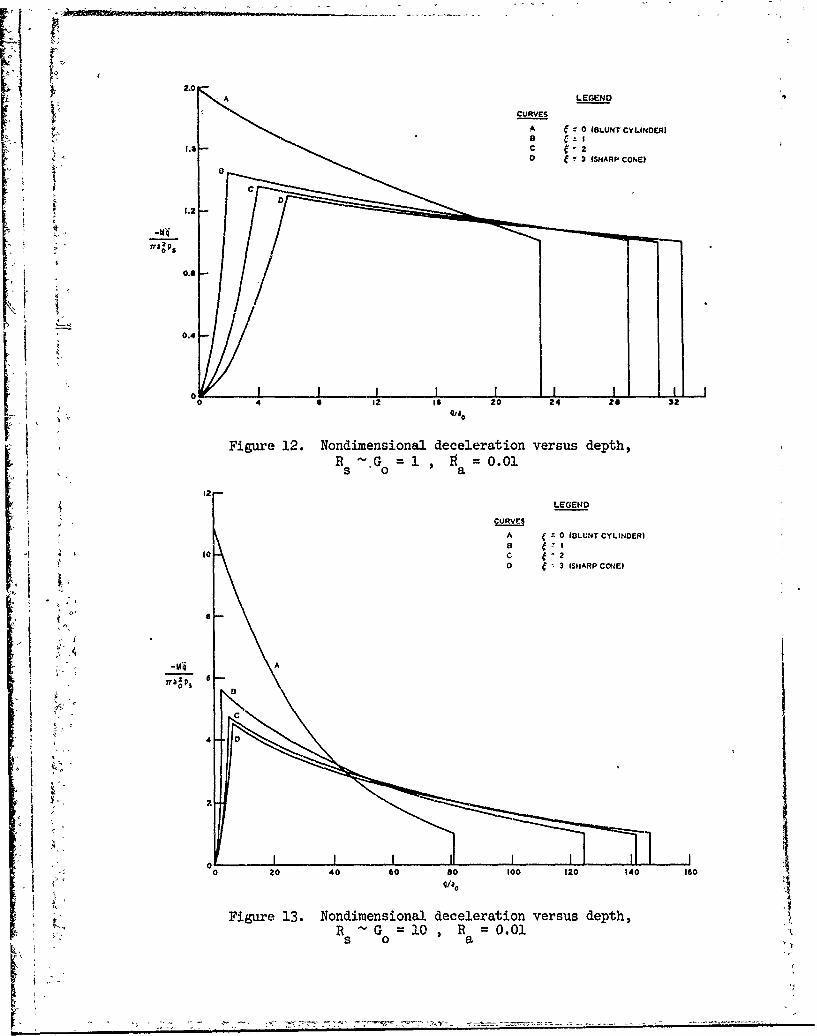
FThe Shape of the Deceleration Curve
36. Probably the most stringent test of the present penetrationtheory lies in the comparison of predicted deceleration versus depth ortime with experimental observations and with the results of detailed
two-dimensional finite-difference calculations, where available. For
the moment, however, attention is focused on the shape of the decelera-
tion curve in order to make a qualitative comparison with experimental
results. Projectiles with conical noses are amenable to such an exam-
ination because of the simplicity of Equations 108 and 109, but it is
emphasized that similar results can be obtained for ogives.
37. The deceleration curve has the same general shape whether
depth or time is chosen as the abscissa. The overall shape of the curve
is strongly dependent on G - R and on 1 = L/D . This is illus-0 s
trated in Figures 12 and 13. The increasing portion of the curve cor-
responds to the embedding of the nose, and the decreasing portion cor-
responds to a fully embedded nose. Examination of experimental
results'' reveals that many observed deceleration curves tend to
be somewhat flat after the nose becomes embedded in the target, thus
having the general shape of the curves in Figure 12 (at least for earth
penetration), but the rapid decay shown in Figure 13 is rarely seen.
The present penetration theory leads to reasonably accurate predictions
of final penetration depth for 0 < R < 100 , but only the averagevalue of the deceleration is correctly predicted when R is signifi-cantly greater than one. Moreover, the theory apparently overpredicts
the instantaneous target inertial resistance during the early part of
the penetration process, and the magnitude of this overprediction in-
creases as R increases from one. The net result is that the theory
tends to underpredict final penetration depths when R is very large5
at impact.
40
B
0.G 1 0=00
Figure 12. Nondimensional deceleration versus depth,Rs o a .0
2 LEGEND
CUR VESA 0 IOLUNT CYLINDER)
soC 20 I 3 iSIIARP CONE)
M'4 A
Figure 13. Nondirnensional deceleration vesu eph

The Relative Effects of Nose Shape and Frontal Loadingon .Final Depth of Penetration
38. In the context of the present penetration theory, the effect
of nose shape is coupled with the effects of Ra and G Rs , so that
the final depth of penetration will not be proportional to some function
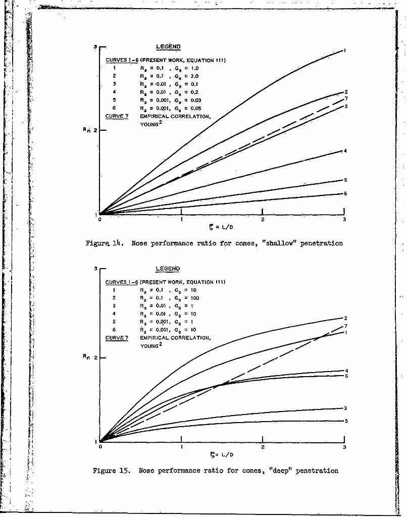
of nose shape alone. The nose performance ratio Rn is now defined as
_(no)
where q is the final depth of penetration for a projectile with a
given nose shape, and qTb is the corresponding quantity for an other-
wise identical blunt cylinder (4 = 0). Combining Equations 104 and 110
leads to
In (1 + fn G ou ) + 6f nRaSn olnR ~ ~ n = o p 11
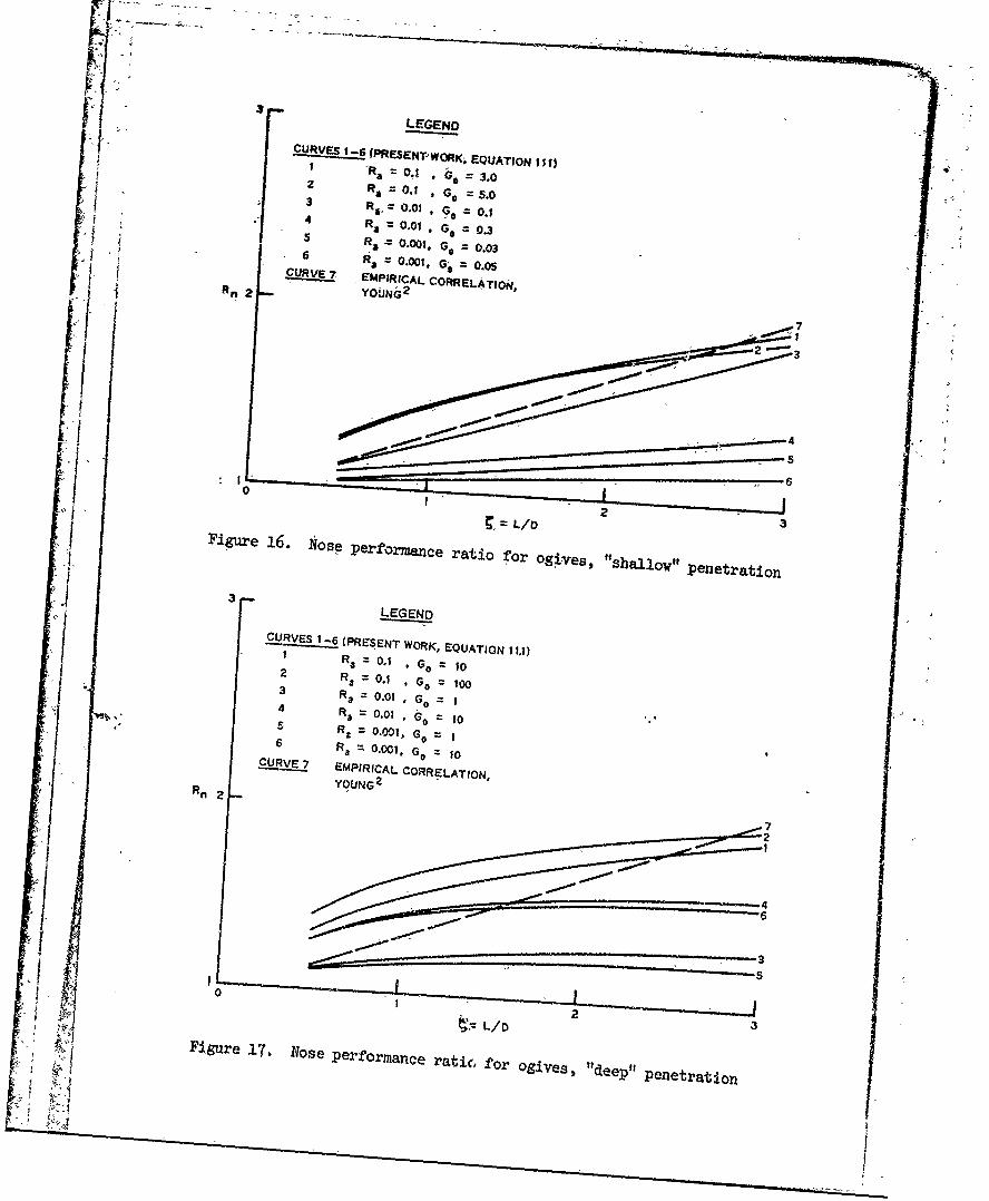
where u is given by Equation 105. In Figures 14-17, Rn is plotted
versus 4 for cones. and ogives with Ra and GO as parameters. Fig-
ures 14 and 16 correspond to shallow penetration depths on the order
of a few nose lengths, and Figures 15 and 17 correspond to depths sev-
eral times deeper than Figures 14 and 16. The values R a 0.1 andaR = 0.001 were chosen to conform approximately to the upper anda
lower limits of R in penetration tests conducted by Sandia Labora-15,16 a
tories, and the value R = 0.03. represents an intermediate value.a 2
For comparison Young's empirical correlation is inclided in Fig-
ures 14-17. Young's linear relation between 4 and final depth of
penetration was deduced from earth penetration data for a variety of
projectiles and impact conditions and represents something of an overallU2average nose shape effect.
2
39. The present theory results in a nose shape effect which be-
comes more pronounced-as R increases. This simply means that, for
a given projectile diameter, a sharp nose is less effective for a heavy
'I projectile than for a light projectile as far as depth of penetration is
42
CURVES 1-6 (PRESENT WORK, EQUATION I11t)I R=0.1 G .
2 Ra =0.1' Go =2.0
5 Ra 0.001, Go,. 0.033t Ra 2 .0,G .500
RIi 2 00.-
0 I23=L/D
Figure, 14. Nose performance ratio for cones, "shallow" penetration
.3 LEGEND
4 A CURVES 1-6 (PRESENT WORK, EQUATION I111)I Ra= 0.1 ,G 0 =10
2 R a = 0.1 Go = 1003 RaO=*0.01 Go = 1'4 RaO.01 G 102
Rn 2 H4
0 1 2 31:= L/D
Figur'e 15. Nose performance ratio for cones, "deep" penetration
LEGEND
CURVs 1.6'PRESENT-WOK. EQUATION I If)2 R =1 0.1 9G= 3.0
3I R, = 0.01 = G 0 .-4 RaO=.001 G, =o.35 Ra 0.001. G = 0.03aR .00t, =, 0.0 6
C-UIRVE?7 EMPIRICAL CREAIhI R~ 2 Y O I)N 6 2 C R E A II7
/ 0~] ~ ~~Figure 16. 1I0ose Performance ratio for ogives, ft s al w pe e at o
1 3LEGEND
CURVES 1-6. (PRESENT WORK, EQUATION I1,I)1 Ra 0-=1 ,Go 02 RaO.1 *Go 100I3 Ra O.01 G G= I
4 Ra= 0.01G= 105 RX 0-001, Go=0
6 Ra = .001,GO=1j Rn YOUNG 2
Figu e 17 fl se p rfo manc -7
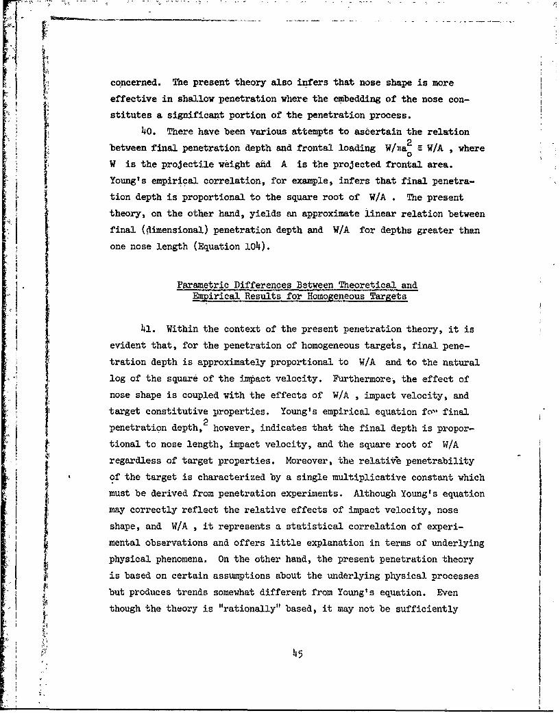
Sconcerned. ise present theory also infers that nose shape is more~effective in shallow penetration where the embedding of the nose con-
stitutes a significant portion of the penetration process.~40. There have been various attempts to asdertain the relation
between final penetration depth and frontal loading W/wa W/A , where0
W is the projectile weight ahd A is the projected frontal area.
Young's empirical correlation, for example, infers that final penetra-
tion depth is proportional to the square root of W/A . The present
theory, on the other hand, yields an approximate linear relation between
final (dimensional) penetration depth and W/A for depths greater than
one nose length (Equation 104).
Parametric Differences Between Theoretical and
Empirical Results for Homogeneous Targets
41. Within the context of the present penetration theory, it is
evident that, for the penetration of homogeneous targets, final pene-
tration depth is approximately proportional to W/A and to the natural
log of the square of the impact velocity. Furthermore, the effect of
nose shape is coupled with the effects of W/A , impact velocity, and
target constitutive properties. Young's empirical equation fo- final
penetration depth,2 however, indicates that the final depth is propor-
tional to nose length, impact velocity, and the square root of W/A
regardless of target properties. Moreover, the relative penetrability
of the target is characterized by a single multiplicative constant which
must be derived from penetration experiments. Although Young's equation
may correctly reflect the relative effects of impact velocity, nose
shape, and W/A , it represents a statistical correlation of experi-
mental observations and offers little explanation in terms of underlying
physical phenomena. On the other hand, the present penetration theory
is based on certain assumptions about the underlying physical. processes
but produces trends somewhat different from Young's equation. Even
though the theory is "rationally" based, it may not be sufficiently
45

realistic; A more realistic theoryk mitght result in trendssimilar to
those exhibited by Youg's equation.
t: Penetration of Layered Targets
4: 2. The relativiely complex treatmeint of the layered target in
Part II is important for predict.Ing projectile loading when the initial
layer thickness is comparable to the projectile hiose dimensions and/or
when the layers have extremely different ,properties., On the other hand,
when the layers are thick and have fairly similar properties, final
depth predictions, which approxiatethe results of the layered target
theory can be obtained simply by using the ,theory for homogeneous tar-.
gets and changing the material property #nput when the projectile reaches
a layer interface.
2I 46Selsic oe elsi t heoy 6gtrsl nted smlrt
[1- tbs xibtdb Yugs.qa~n
Peeiain fL-eedTrgt

PART IV: APPLICATIONS OF PENETRATION THEORY
Introduction
43. The penetration theory presented in Part I! is relatively
simple compared with two-dimensional finite-difference analyses. In-
order to demonstrate in part the applicability of the theory as an engi-
neering tool, theoretical results will be compared with two-dimensional
finite-difference solutions, empirical results, and experimental 0bser-
vations. However, before these comparisons are made, some comments are
in order:
a. Although the ratio R << 1 in all the examples to bea3
presented, the added mass term ap B 1 will be retained
as an upper limit on the effect of target acceleration.
b. It will be shown that the solid Reynolds number Rs
provides a simple rule of thumb which indicates whether
or not the present theory is appropriate for a particular
L penetration problem.
c. Material properties and impact conditions are given in
both U. S. customary and metric (SI) units in the text,
[ but graphic presentation of results is given in U. S.
customary units to expedite comparison with other work.
Choice of Material Properties
44. The cavity expansion theory presented in Appendix A and thepenetration theory developed in Part II are restricted to materials
which exhibit bilinear behavior in shear, as shown in Figure A2. More-
overtU.4e assumption of rate-independent shear behavior is implicit in
the theoretical development. Real materials exhibit neither bilinear
shear behavior nor rate-independence, and the guidelines to be followed
when the present penetration theory is applied to real targets are:
(a) bilinear stress-strain curves should be chosen so as to approximate
the total area under experimentally obtained stress-strain curves, up to
47

the point where complete failure occurs (i.e., where the slope becomes
negative); and (b) when predictions are to be made prior to the penetra-
tion of an untried target, it is best to make two sets of calculations
corresponding to the upper and lower bounds on Y , E , and Bt . Lower
bound properties canr be obtained from the results of static tests, while
upper bound properties must be estimated from the results of dynamic
tests.
Penetration of Rock
45. Thigpen7 has performed two-dimensional finite-difference cal-
culations analyzing the penetration of a nonrigid projectile into Madera
limestone and welded tuff. The present penetration theory is applied to
the same problems for a rigid but otherwise identical projectile. Fol-
lowing Thigpen, the targets are idealized as compressible elastic-
plastic continua of the von Mises type (compressive yield strength Y
independent of pressure). For the range of dynanic pressures considered
(P< V 0 ), the relation between pressure and density is
1P _ave)
where Pave is average dynamic pressure in the plastic zone (Appen-
dix B), and C is initial sound speed. The modulus E is essentially0
constant for the range of pressures examined. For the limestone,
p 168 pcf* (2.69 gm/cm 3 )
E 3.15 x 10⁶ psi (217 kbar)
Y = 1.37 x 10⁴ psi (0.945 kbar)
* A table of factors for converting U, S. customary units of measure-ment to metric (SI) units is presented on page It.
:_ 48
I ', and
C = .12 x 10 fps (3.l x lo0 m/sec)0For the tuff,
p = 115 pcf (1.84 gm/cm3 )
|6
E 1.09 x 10⁶ psi (75.2 kbar)
Y = 5.51 x 10³ psi -(0.380 kbar)
and
C0 =6.72 x 10³ fps (2.05 x l03 m/sec)
For limestone penetration,
W = 67h lb (306 kg)
D = 8 in. (20.3 cm)
L/D = 3.0 (9.25 CRH)
and
v = 570 fps (174* m/sec)
For tuff penetration,
W = 1000 lb (1154 kg)
D = 9 in. (22.9 cm)
L/D = 2.4* (6.0 cRi)
and
v = 695 fps (212 m/sec)
h6, The predictions of the present penetration theory are com-
pared with Thigpen's results in Figures 18 and 19. Thigpen's decelera-
tion curves correspond to the motion of a particle on the projectile
axis of symmetry; in Figure 18 the particle is located 2 ft (61 cm) aft
4*9

A'1
[I2.4 Goo 16000
K I 2. 500 -. ~~-~.VELOCITY 50
~-EPTH
400 DECELERATION 40
1.2 ~300 -3000w
w
00.6 200 2000
0.4 100 TW-DM00INA
0 0 -TIME, MSEC
Figure 18. Motion curves for penetration into limestone
7 700 L:ErGND -2800TW~O-AMENSIONALFINITE -OIFF ERE NCERESULTS, T1I[GpEN
7
- -PRESENT WORK6 600 2400
5 500 2000
4- ?400 [b00
3 ~300 1200 0> w
UDECLCflA9IO to
2 .200 1 4100
I 100 400
0- 0 0
TIME, USC
Figure 19. Motion curves for penetration into tuffI

of the nose tip, and in Figure 19 the particle is locafted at the base ofthe nose. The oscillation in Thigpen's deceleration curves is due to
nonrigidity of the projectile. 7 It is important to observe that in
these calculations the target shear resistance is very significant since
the values of R at impact are 0.86 and 2.17 for the limestone and5
tuff, respectively. Moreover, the agreement with Thigpen's results
apparently provides justification for using Ps to characterize average
shear resistance to penetration, at least for homogeneous targets and
low values of R.s
Penetration of Concrete
47. Another test of the present penetration theory lies in thecomparison of theoretical predictions with those of empirical penetra-
tion equations. A fairly accurate efapirical equation for the penetra-
tion of armor piercing (AP) and semi-armor piercing (SAP) bombs into
reinforced concrete is given by17
222WD0 . 2 1 5 /v \1.5+ 0.5D + 15% (113)
with q in inches, W in pounds, A in square inches, D in inches,Y in psi, and v in fps. Equation 113 is now used to predict the
0 18penetration of a 2000-lb (907-kg) AP bomb into reinforced concrete,
with Y = 5000 psi (0.345 kbar), E = 4.10 x 10⁶ psi (283 kbar), and3
p = 150 pcf (2.4 gm/cm 3) . For the penetration theory predictions, the
modulus Et is taken to be zero, and the value of Xis the staticN,
value (5000 psi) as in Equation 113. In addition, the prsasure-density
curve in Figure 20 is used according to the procedure outline in Appen-
dix B and represents typical behavior of concrete under pressure.N'\The
bomb has D = 13.5 in. (34.3 cm) and L/D = 1.12 (1.5 CRH) . Normal\
impa, .. velocities range from 500 to 1500 fps (152 to 457 m/sec). Two
sets of theoretical predictions are made, corresponding to the compress-
ible and incompressible cases. These are compared with the results
51
- ---i-----.--.--,.* .. ~ . -

80 1
II
I.I
70
INITIAL DEST4.6SU/ 3
60
!-0
1 30
I" $
20
I 10
4.5 4.6 4.7 4.0 4.9 5.0 5.1
DENSITY. SLUGS/FT3
Figure 20. Typical pressure-density relation forconcrete (1 ksi = 1000 psi)
of Equation 113 in Figure 21. Since the penetration theory predictions
are made us4ng the static value of Y , they should be regarded as upper
bounds on predicted penetration depth. The results in Figure 21 corre-
spond to impact values of R in the range 1 R s 15 , in which the
inertial resistance of the target begins to predominate over the shear
resistance. Moreover, the agreement with Equation 113 provides some
A ; Justification for using the theory in this range of values of R" sI52
;%,xi . -

160 LEGEND
I EMPIRICAL RESULTS, EQUATION 113
PRESENT WORK-COMPRESSIBLE
140 PRESENT WORK-INCOMPIRESSIBLEz
120
ILI 1/z
w/
U60
40
20S00 700 S00 1100 1300 1500
IMPACT VELOCITY, F'PS
Figure 21. Penetration depth versus impact velocityfor penetration of concrpete by a 2000-lb AP bomb
Penetration of Soft Earth
8.As an example of penetration into soft earth, the normal im-
pact of a terminal delivery vehicle (TDV) into moist, sandy clay is con-
sidered. The target is one of the range areas at Jefferson Proving
53
719L
Ground, Indiana. The TDV has a total weight of 17.3 lb (7.85 kg), but
when the full length of the projectile is embedded in the target, the
projectile base separates, remaining at the target surface and reducing
the projectile weight to 13.6 lb (6.17 kg). The diameter of the pro-
Jectile is 3 in. (7.62 cm), the total projectile length is 17.7 in.
(45.0 cm), and the nose is an ogive, L/D = 1.45 (2.35 CRH). For the
target, Y = 50 psi (3.45 bar), E = 3000 psi (207 bar), and Et = 0,19
obtained from dynamic unconfined compression tests. The undisturbed
target density p = 3.88 slugs/ft3 (2.00 gm/cm3. Experimental impact
velocities range from 350 to 610 fps (107 to 186 m/see) corresponding to
65 < R <S 200 . Since no pressure-density curve is available for thes
target, two sets of calculations are presented, corresponding respec-
tively to the incompressible case and the compressible -case for
pt = 1.1p (probably representing a high upper limit on the effect of
compressibility). The theoretical predictions are compared with experi-
mental results in Figure 22. Since the experimental data are quite
scattered, it is difficult to come to any definite conclusions from this
comparison. However, within the framework of the theory, the incom-
prbssibile calculation is probably the more realistic of the two,
alt hough the predicted depths are somewhat low compared to the experi-
me tal results. Viewed in this light, the results seem to indicate that
R - 100 may represent an approximate upper limit on the range of ap-
p Icability of the pre..ent penetration theory.
Perforation of a Metal Slab
49. Perhaps the most stringent test which can be applied to the
penetration ,theory for layered targets developed in Part II is a situa-
tion in which the first layer is thin with extremely different proper-
ties from the second layer. Such a situation exists when a steel pro-
jectile with a diameter of 0.3 in. (0.762 cm) strikes a 6061-T6aluminum slab with a thickness of 1 in. (254 cm). This, of course,
represents a case where the first layer is aluminum and the second layer
is air. Using the HEMP code, Wilkins2 0 has performed a two-dimensional
54

120
0
- 100
80
*0 a 80
zo
IL
SL EGEND~
P~~~,t ., NY WQ RK-COMPRESSIBLE, p4 1.1 , p
- " l . ~r W',AK-INCOMPRESSIELE, p1 p
0 a*rLhk TAL. P EULTS1 9
a 0
ii j I I I I I
-4 503 600 30
Figure 22. Penetration depth versus impact velocity for pene-tration of sort earth by a terminal delivery vehicle
finite-difference analysis of the perforation of l-in.-thick aluminum
slab by a 0.3-in.-diam steel projectile. The projectile has a conical
, nose, L/D = I , a weight of 0.0183 lb (8.30 gin), and a normal impact, velocity of 2756 fps (81i0 m/sec). For the aluminum, p = 5.25 slugs/ft3
3
(2.7 gm/cm3), Y = 1i3,500 psi (3 kbar), E = 1.03 x 10⁷~ psi (710 kbar),
and Et =0 * The pressure-density relation is Equation 112 with
z7
:pC 2 = i.24 x 107 psi (775 kbar). The properties of air are considered
* negligible compared to those of aluminum. According to Wilkins, the
projectile perforates the slab with an exit velocity equal to 81 percent
of the impact velocity. This represents a projectile momentum loss of
55
Ca.

19 percent and a-kinetic energy loss of 34.4 percent. The present pene-
tration theory for layered targets has been applied to the same problem,
athdthe results are presented in Figures 23-26. The crucial test of the; theory lies in i's ability to predict projectile kinetic energy loss
during the perforation processi The incompressible theory yields an
2energy loss of 54 percent, and the compressible theory reduces this to
52 percent, essentially the same answer. Thus, the present theory over-
predicts Wilkins' value for the energy loss by a minimum factor of 1.51.
f F Two possible sources of error are immediately apparent: First, as is
pointed out in Part III, paragraph 37, the theory apparently overpre-
dicts the initial target inertial resistance when the value of R is~ssignificantly greater than one at impact (in this case, R = 6.29 ats
impact). Second, the target is always assumed to be in a compressive
state of stress; however, it is well known that because the backside of
the slab is a free surface, a finite region in the slab may be in a ten-
sile state of stress during the perforationprocess, thus reducing the
overall penetration resistance.
50. Within the framework of the theory as it stands, there is
little that one pan do about the suspected region of tensile stress, and
this may represent a permanent limitation on the theory. On the other
hand, the question of inertia is a bit more straightforward. Accord-
ingly, a third calculation is presented in which the target is assumed
incompressible, and the inertial terms in the projectile equation of
motion are discarded altogether. For this case, the predicted energy
loss is 32 percent, slightly underpredicting Wilkins' value of 34.4 per-
cent. This does not necessarily mean that all the target resistance is
due to shear. However, it may indicate that the theory does a better
job of predicting target shear resistance than predicting target inertial
resistance. In any case, it is emphasized that the present theory is
developed not as a perforation theory, per se, but as a penetration
theory for layered targets. For most cases of practical interest, the
layers will have comparable densities (i.e. comparable inertial resis-
tance) even though other properties may bt. radically different. Since
the application of the layered-target theory to a perforation problem
• 56
t1.2[ LEGEND
A " PRESENT WORK-INCOMPRESSIBLE
~PRESENT WORK-COMPRESSIBLE
1,0 -- PRESENT WORK-INCOMPRESSIBLE,.0INERTIA NEGLECTED
rA
x
Li r0.4 / \
/ "_
PENETRATION DEPTH, ITN E
. Figure 23. Projectile deceleration versus depth for perforationJof l-in.-thick aluminum slab
.57
/

'! ... ... ..... .. .. ... .. ........1 -0. "
1. 0. Ii
zwa 0.4 -
I--:
E 'LIEGEND
;iA PR.ESEfiT WORK-INCOMPRESStBLE
0.2 . .. PRESENT WORK-COMPRESSILE"
PRESENT WOR K-1 NCOM PRESS IBLE,INERTIA NEGLECTED
0 HEMP CODE RESULTS, WILKINS2 0
A0
0 0.2 0.4 0. 0.*" 1.0 0.
PENETRATION DEPTH, IN.
Figure 24. Projectile kinetic energy versus depth for: ! perforation of l-in.-thick aluminum slab
.0
0.
I -
8 0.4
0>1_ LEGEND
4 PRESENT WORK-INCOMPRESSIBLE
0.2 PRESENT WNOrK-COMPRESSIBLE
- PRESENT WORK-INCOMPRESSIBLE,INERTIA NEGLECTED
0 HEMP CODE RESULTS, WILKINS2 0
to 20 3,0 40 so 6 0
{- TIM:E. ASEC
Figure 25. Projectile veloci er versus time for perforationperfor of -in.- thick aluminum slab

1.6
P" P
1.4 /
1.2
1.0/
V./
(L
=w
i ' /
0.6
0.4 LEGEND
PRESENT WORK-INCOMPRESSIBLE
__ _ PRESENT WORK-COMPRESSIBLE
PRESENT WORK-INCOMPRESSIBLE
INERTIA NEGLECTED0.2 0 HEMP CODE RESULTS, WILKINS 2 0
0 I I I I I
0 10 20 30 ,0 so 60
TIME, /SEC
Figure 26. Penetration depth versus time for perforationof l-in.-thick aluminum slab
'1q

represents,& very extreme case ndyesfarrutthtery prob-
ably-u;epresents, a reasonable extension, of the penetration theory for[ hamogeneous targets.
.Oblisue-Impact- Mainst Hard Eaith
51. At the present time, no data for oblique impact and ricochethave been found which are appropriate for comparison with -the oblique -
impact theory developed in -Part II, i,.e.,. in the experimental results
found to date, there is not enough information given about projectiles
(eirg., CG location aiid moment of inertia) to effect a reliable test of
-the theory. -Nevertheless, an application of the thebr to the oblique
- - impact of a TDV against a hard earth target is mnade withjout experimental
verifid&tion and is presented as a sample calculation. The p~rojectile
characteristics are
W 15 lb (6.8o kg)
1=0'095-2 21- .95 slu'g-ft (0.1321-g-rn
Z G =.4in. (23.9 cm)
D 3.0 in (7.62 cm)
and,
1.9
The target is equivalent to frozen sand found at Camip McCoy, Wisconsin, 1
- - with
P =t 3.21 slugs/ft3 (1.66 gm/cm3)
Y.= 958 psi (66.1 bar)
6o

E 6.25 x 10 psi (4.31 kbdr) r~ and
Et 0
(These properties have been previously used in the analysis of TDV
impact and penetration at-Camp McCoy.'19) The initial angle of obliquity
is 45 deg (0.76 rad), and the impact velocities considered are 300 fps
(91.4 m/sec) and 600 fps (183 m/sec). Initial and final projectile
positions are illustrate, for each impact velocity in Figures 27 and 28,
demonstrating the dependence of vehicle rotation on impact velocity. In
the 300-fps case, the projectile undergoes a rotation.of 15.1 deg, andIthe downward motion of the CG is stopped before the nose is fully em-bedded. In the 600-fps case, the projectile undergoes a rotation of
4.17 deg during the embedding of the nose. The curve connecting the CG
- locations is the CG trajectory.
CG
j 4-
H --2
Figure 27. Oblique impact of TDV against hard earthfor w 45 deg and v = 300 fps
Y" fo61

C CG
V j Figure 28. Oblique impact of TDV against hard earth f'orwo 4 5 deg and v 0=600 fps
62

PART V: CONCLUSIONS AND RECOMMENDATIONS
52. The results presented in Part II stand as partial evidence
that the cavity expansion theory can be used as an approximate basis for
the development of a projectile penetration theory, particularly when
the effect of shear is predominant (i.e., for low values of the solid
Reynolds number R ). However, it is emphasized that the analogy be-
tween spherical cavity expansion and projectile penetration is somewhat
fortuitous, and the present penetration theory probably reflects only
the gross features of the projectile-target interaction. Thus, the
acquisition of insight into the mechanics of penetration demands the
application of whatever means are available, including empirical methods
and two-dimensional finite-difference analyses.
53. For estimates of penetration depth, the applicability of the
present penetration theory appears to lie in the approximate range
0 < R s< 100 ; but the upper bound is offered as a conservative rule ofs
thumb and not as an absolute limit. (Results of experimerts at high
values of R are needed in order to establish a more redlistic range.)5
However, it is important to note that as R + O the problem of dynamicS
penetration reduces to that of a static punch, in which friction may be
important. On the- other hand, as R + - shear resistance becomess
insignificant such that the projectile-target interaction may reduce
essentially to a fluid dynamics problem.
54. Although some footholds have been established, the develop-
ment of the penetration theory is still in an embryonic stage; some sug-
gestions for additional work are listed below:
a. At the present time, the role of target inertia in the
projectile-target interaction is only partially under-
stood, and the degree of contact between the projectile
nose and the target has not been established. Conse-
quently, further investigation is necessary to establish
the distribution of dynamic pressure on the projectile-
target contact surface as a function of projectile veloc-
ity, nose shape, and target properties.
63

b. Although the cavity expansion shear resistance term ps
seems to represent a reasonable first approximation for
average normal stress at the projectile surface due to
shear in the target, some effort should be directed
toward establishing normal and tangential stress compo-
nents on the projectile .surface due to target shear
behavior. Furthermore, the variation of these quantities
with nose shape, penetration depth, and confining pres-
sure should be determined.
c The present oblique impact theory is limited to the
embedding of the projectile nose, with all rotation
occurring in a single plane. Moreover, this work has not
been verified experimentally. Future efforts should
first assess the accuracy of the existing theory. Then,
if necessary, the theory can be extended to include aft
body effects and motion in three dimensions. Eventually,
it may be possible to formulate a workable theory for
deep penetration at finite angles of attack and obliquity.
However, it is emphasized that overcomplication is as
undesirable as oversimplification, and modification of
the theory should proceed one step at a time to avoid the
incorporation of superfluous details.
64.

REFERENCES
1. Rohani, B., "Fragment and Projectile Penetration Resistance ofSoils; High-Velocity Fragment Penetration into Laboratory-Prepared
Soil Targets," Miscellaneous Paper S-71-12, Report 2, Jun 1973,U. S. Army Engineer Waterways Experiment Station, CE, Vicksburg,Miss.
2. Young, C. W., "Depth Prediction for Earth-Penetrating Projectiles,"Journal, Soil Mechanics and Foundations Division, American Societyof Civil Engineers, Vol 95, No. SM3, May 1969, pp 803-817.
3. Classified reference.*
4. Classified reference.
5. Hageman, L. J. and Walsh, J. M., "HELP--A Multi-Material EulerianProgram for Compressible Fluid and Elastic-Plastic Flows in TwoSpace Dimensions and Time," 3SIR-350, Vol 1, 1970 Systems, Science,and Software, La Jolla, Calif.
6. Sedgwick, R. T., "Theoretical Terminal Ballistic Investigation andStudies of Impact at Low and Very High Velocities," Technical Re-port AFATL-TR-68-61, 1968, Space Sciences Laboratory, GeneralElectric Company, King of Prussia, Pa.
7. Thigpen, L., "Pojectile Penetration of Elastic-Plastic Earth
Media," Journal, Geotechnical Engineering Division, AmericanSociety of Civil Engineers, Vol 100, No. GT3, Mar 1974, pp 279-294.
8. Bishop, R. F., Hill, R., and Mott, N. F., "The Theory of Indentationand Hardness Tests," Proceedings, Physical Society (London), Vol 57,1945, pp 147-159.
9. Goodier, J. N., "On the Mechanics of Indentations and Cratering inSolid Targets of Strain-Hardening Metal by Impact of Hard and Soft
Spheres," Technical Report 002-64, Jul 1964, Stanford ResearchInstitute, Poulter Research Laboratories, Menlo Park, Calif.
10. , "On the Mechanics of Indentation and Cratering inSolid Targets of Strain-Hardening Metal by Impact of Hard and SoftSpheres," Proceedings, Seventh Hypervelocity Impact Symposium,Vol III, Tampa, Fla., Feb 1965, pp 215-260.
11. Ross, B. and Hanagud, S., "Penetration Studies of Ice with Applica-tion to Arctic and Subarctic Warfare," Final Report, Project 7000-1452, Sep 1969, Stanford Research Institute, Menlo Park, Calif.;prepared under Contract N0001-68-A-0243, NR 2711-008 for SubmarineArctic Warfare and Scientific Program, Naval Ordnance Laboratory,Silver Spring, Md., and the Office of Naval Research, Washington,D. C.
* Bibliographical material for the classified references will be fur-
nished to qualified agencies upon request.
65-------

12. Hanagud, S. and Ross, B., "Large Deformation, Deep PenetrationTheory for a Compressible Strain-Hardening Target Material," AIAA '
Journal, %ol 9, No. 5, May 1971, pp 905-911.
13. McNeil, R. L., "State of the Art," Proceedings, 'Conference on RapidPenetration of Terrestrial Materials, Texas A&M University, CollegeStation, Tex., Feb 1972,, pp 11-125.
14. Young, C. W. and Ozanne, G. M., "Compilation of Low Velocity Pene-tration Data," Research Report .1o. SC-RR-66-306, Jun 1966, SandiaLaboratories, Albuquerque, N. Mex.
15. Young, C. W., "Low Velocity Penetration Tests in Natural Earth .Targets of Selenite and Gypsite," Development Report No. SC-DR-66-2695A, Apr 1967, Sandia Laboratories, Albuquerque, N. Mex.
16. Yih, C. S., Fluid Mechanics, McGraw-Hill, New York, 1969, p 107.
17. Headquarters, Department of the Army, "Protective Design: Funda-mentals of Protective Design (Non-Nuclear)," Technical Manual 4
TM 5-855-1, Jul 1965, Washington, D. C. 4
18. Lin, T. Y., Design of Prestressed Concrete Structures, 2d ed.,Wiley, New York, 1963.
19. Rohani, B., "Penetration Performance of Terminal Delivery VehicleT-98WA into Soft and Frozen Ground: Analyses Based on Both Field
; . Test Results and Theoretical. Calculations," Nov 1973, U. S. Army
Engineer Waterways Experiment Station, CE, Vicksburg, Miss.
20. Wilkins, M. L., "Penetration Mechanics," Preprint No. UCRL-72111(prepared for submittal to Yale Scientific Magazine), Nov 1969,Lawrence Radiation Laboratory, University of California, Livermore,Calif., cited with permission of the author.
-21. Hildebrand, F. B., Advanced Calculus for Applications, Prentice-Hall, Englewood Cliffs, 1962, pp 53-54.
22. Lamb, H., Hydrodynamics, 6th ed., Dover Publications, New York,19h5, p 122.
6:66 i66
APPENDIX A: SPHERICAL CAVITY EXPANSION INA CONCENTRICALLY LAYERED MEDIUM
Introduction
1. This appendix presents an extension of cavity expansion the-"* 10
ory developed by Bishop, Hill, and Mott, Goodier, and Hanagud and.12
Ross. Goodier's treatment dealt with the dynamic expansion of a
spherical cavity in an infinite, incompressible, elastic-plastic,
strain-hardening medium. By means of a locking approximation in which
the plastic zone is assumed to be uniformly compressed, Hanagud and Ross
modified the theory to account for the case when the effects of compres-
sion predominate over the effects of shear. However, the inertial terms
in the Hanagud-Ross treatment do not reduce to those of Goodier for the
Srincompressible case. The present work eliminates this co.-tradiction and
also accounts for the effect of concentric layering.
2 IFgrp aProblem Formulation
2. In Figure Al, a spherical cavity of radius a(t) is surrounded
LEGEND
/ (t h(t) a =CAVITY RADIUS
b = RADIUS OF PLASTIC FRONT
/ \h = INTERFACE RADIUS
i t = TIME
ff, , , NO. I'LAYER
4 Figure Al. Spherical cavity surrounded by concentric layers
Raised numbers :efer -to similarly numbered items in "References on
pp. 65-66 at end of main text.
Al

by two cofidentric layers of different materials. Both materials are
eElstic-plastic with linear strain-hardening, 9 1 2 as illustrated in
Figure A2.
1<Y
W
SHEAR STRAIN
Figure A2. Material behavior in shear
Both materials are incompressible in the elastic and plastic states, butJ htransition from the elastic to the plastic state is accompanied by a
finite volumetric strain e . This quantity is known as a locking
strain 12 and is introduced in order to obtain a first approximation
to the effect of compressibility. Although e£ is taken to be constant
in the present analysis, it must be a function of pressure to have any
physical meaning. However, the variation of c with pressure does not
alter the analysis or conclusions of this appendix, and a discussion of
the locking epproximation is given in Appendix B.
3. The elastic and plastic zones are separated by a spherical
plastic front of radius b(t) (Figure Al). Since b(t) is the only
radial location where compression occurs, it also represents a shock
front where density and stress are discontinuous. The equation of mo-
tion for spherical symmetryI '1 2 at r 47h on either side of b(t) isthen
S jA22A

r 2 tD
r r (a - r = g P < r < b (A2)
where
a = radial stressr00C( = tangential stress
j r = radial coordinate
0 = polar coordinate
I v = radial velocity in the elastic region
v -radial velocity in the locked plastic regionIL 4. The material is required to be stress-free as r + = , and the
discontinuity in ar at r = b is defined by
Aab b (A3)
where (b is the limiting value of a as r + b in the elastic
region, and -- is the corresponding quantity in the locked plastic
region. The equation of motion is then integrated with respect to r
from r = ' to r = a , accounting for the discontinuity at r = b , so
that the compressive normal stress at the cavity surface is given by
Swhee p(t) -a (a,t) = Aab + Im(a,b) + Im(b,-) + Is(a,) (Ah)
S where the momentum integrals I (a,b) and I (b,-) aegiven by
a b
and the general shear integral is defined by
.I, A3
f f2[ " • b
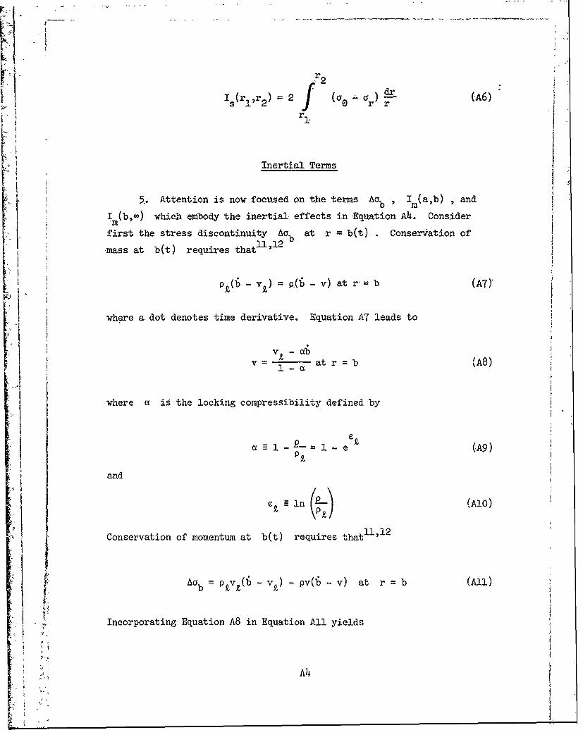
r2
I(rl 3 r 2 ) 2 (a a r) (-A6)
Inertial Terms
5. Attention is now focused on the terms Ab , Im(a,b) , and
I (b, ) which embody the inertial effects in-Equation Ak. Consider
first the stress discontinuity Aab at r = b(t) Conservation of
mass at b(t) requires thatU2 l p vb
pt( -v&)=0( v) at r,= b (AT)'
where a dot denotes time derivative. Equation A7 leads to
v£- czb
v - at r b (A8)
where a is the locking compressibility defined by
a- --1 - 1 - e (,A9)Pk
and
C9 ln (--) (Ala)
Conservation of momentum at b(t) requires that11 '1 2
b = 0 b - v£) - pv(b - v) at r = b (All)
* IIncorporating Equation A8 in Equation All yields
,Ak
I, A
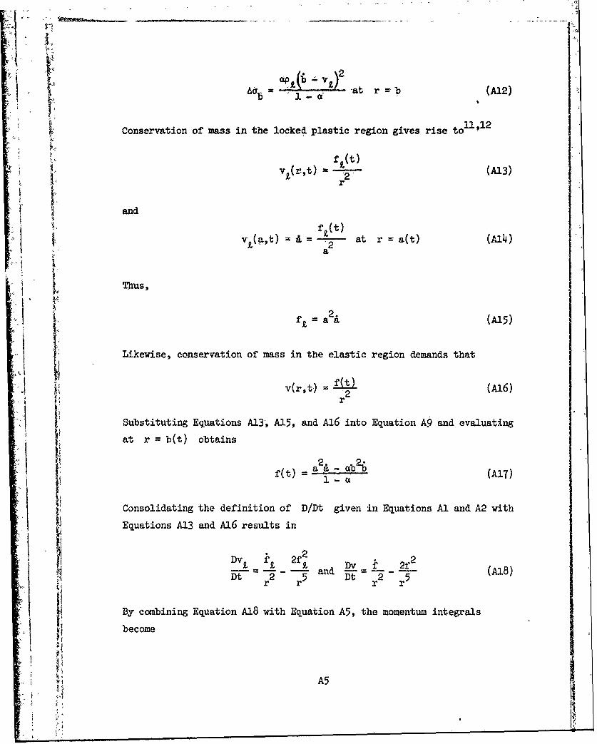
3211Conservation of mass in~ th lcked( plat rongie rise to~ A2
f(tv 9 (r,t) 1 2- (A13)
r
andft( t)
v9( t2 at r =a(t) W
Thus,
f a (Al5)
Likewise, conservation of mass in the elastic region demands that
v(r,t) = c t) (A16)r2
Substituting Equations A13, A15, and A16 into Equation A§ and evaluating
at r =b(t) obtains
2. 2-f(t) aa ab (A17)I:Consolidating the definition of D/Dt given in Equations Al and A2 with
Equations A13 and A16 resul~ts in
v1 9 . 2f2 22- - and -- - (A18)Dt- 2 r5 Dt 2 5rr r r
By combining Equation A18 with Equation A5, the momentum integrals
become
A5

I~,b) 1 b C -2 (A19)
and
I (b,) = -2 (A20)r" r. b
6. So far, the discussion has avoided explicit consideration of
the layer interface h(t) . However, the location of b(t) relative to
h(t) determines the character of the momentum integrals I (a,b) andm
M (b,-) as well as the stress discontinuity A b . Denoting first and
second layer properties by the subscripts 1 and 2, respectively, examine
the situation when b < h in Figure A3 below.
LEGEND
a =CAVITY RADIUS
h b = RADIUS OF PLASTIC FRONT
h = INTERFACE RADIUS
Figure A3. Relative location of cavity surface, plasticfront, and layer interface when b < h
For this case,
f 2f2
Im(ab) =P dr b < h (A21)m kf(r2 r5)
and
-_--A6

f 22S(-2 - - 2 -) d "b < -h (A22)
Evaluating integral in Equations A21 and A22 and employing Equation A13
in Equation A2 result in the inertial terms (Equation A) for b < h
as follows:
A b 1 b, (b 2 b< h (23)'
I C1,b) p f2 b < h (A24)z~eb) o a 2 k - f7. -
, = 1 + -1 -f [+ 1
7. In contrast to Figure A3, Figure A4 illustrates the situation
when b >,h.
LEGEND
a =CAVITY RADIUS
~~ = INTERFACE RADIUS
= RADIUS OF PLASTIC FRONT
Figure Au. Relative location of cav" y surface, layerinterface, and plastic front when b > h
For this case,
Im(ab) r 2 - 2 r + p 2 f2 dr
b > h (A26)
A7

- V_ --
and
V 0I< j(b,6-) = f (L2 42}2-) d b >h (A27)
Evaluating the integrals in Equations A26 and A27 and 'substituting Equa-
tion A13 into-Equation A12 result in the inertial terms (Euqation A4)1 for b >h:
2 pk
= , b>h (A28) $
A- If -_ -t 2 b 2 A9
I 1
(a~bb
\/
'M k£i+ A(h )
122
f2 2(h 4 4 b >h (A29)
I(b,-) = p2 - b > h (A30)2b4 '
Shear Terms
8. Consider the term Is (a,-) , which constitutes the effect of
shear in Equation A4; the appropriate stress-strain relations1 2 are ex-
pressed as
2E(se e r elastic state
aG - ar =(A31)r 2 -
Y + Z- Et(Ce- ) plastic state
where E and Et are elastic and strain-hardening moduli, Y is
yield strength, and c and s are radial and tangential strains.
-- - . IA8

1*
The. locking assumption implies that
o , elastic state
er.+ 2c = (A32)
ej , plastic state
A
The quantities E , Et , Y , and e., are material constants. It is
appropriate to express the tangential strain as 9 1 2
O Inr (A33)r0
where r and r are initial anod instantaneous particle positions,0
respectively. Combining Equations A31-A33 yields
'2E into r > b
Ce - r (A34)
{ 2Et n r - , r < b-
where the elastic and locked plastic regions are 5eparated by the plas-
tic front b(t) . Note that the shear stress a - ar does not have to
be continuous for Equation A6 to exist; piecewise continuity is suffi-21exssa r=h
cient for existence. A discontinuity in a 0 r exists at r h
since this is the material interface where the material properties E ,
E t , Y , and e k are discontinuous. Another discontinuity in ae rexists at the plastic front r = b(t) where the mat(.rial undergoes a
sudden compression. However, when e. = 0 in Equation A34, there is no
discontinuity in 00 - a at r = b # h . Restricting attention to
situations where «e.1 << 3Y/2E t reduces Equation A34 to
b
2(E - Et) in Y m ' I << 3Y (A35)A t 1
at r b(t) , where b° is the initial position of a particle located
at b(t) . By rearranging Equation A35, the quantity 0 is defined by
A9

in Y (A6b-n - 2(E - Et) (A36)
and it follows that
b -be" (A37)
Conservation of mass in-the elastic region requires that
r -b r -b . r > b (A38)
Substituting Equation A37 into Equation A38 and rearranging results in
in1- _ h- -1 e-3 1in - [ -n , r > b (A39)
rc 3 Lr 3 J
9. In the locked plastic region surrounding a cavity of radius
R(t) and initial radius R , conservation of mass demands that11 '12
0} 0~ R) pt (r - R), R < r < b (Ah0),
which gives rise to
r__ _ 1 c 1 in - -- (*lin - - r3 R < r < b
where
and1/31
Rp* R (Ah2)
Incorporating Equation A39 into the first of Equation A34 and integrating
with respect to r from r = r1 to r = r2 for constant E obtains
AlO

i0
2 f (rj$' ) 3E b r 1 <r < (A14L) !71
~~with the restriction that 8 <« 1 . Likewise, employing Equation Ak1 in
the second of Equation A31 and integrating from r - ro1 to r = 2 for . ,, ~constant Y and Et results in '
rt
rF i r2 ,
2 3Y 3
_' 1 ) < r I r 2 < (A44)
3r 3 3j.
Rr <
(Note: Equations A t4 and A45 are evaluated in e ng ii
tions A42, A and A45 now make evaluation of Equation A6 straight-
~forward. With a(t) and h(t) representing cavities relative to the
" in the same order in Equation A42 by a, , a , and a and then by0h
cna h , and Et = hinsotha
- PAa 7 adP 2h3 Ak6
Pz3m 3 mi
i where the subscripts 1 and 2 denote first and second layer properties.
10. Examining fir-st the case where b(t) < h(t) in Figure A3
2 411
~makes it possible to rewrite the shear term in Equation A4 as
s(a,) = s(ab) + Et + I(h,) , b < h (A17)
Applying Equations A4 and A45 to Equation A 7 then produces
h*. h Andh sota
!0

SIb 4 '~' a*\3 m a*
1 2b1<h (A8)
I" For the case where b(t) > h(t) in Figxure A4, Equation A]47 is replaced
~by I (a,) = I+(a,h) + h,b) + I (b,) b > h (A48)
s s s- s
By means of Equations A44 and A45, Equation A49 is superseded by
Is (a ,) 2Y1 in m 3m
+ 272n a Et '
m1
3m 3]b h
+ 2Y ln-+-E2 h 9 b231m()i 1mi=l
+ 2E2 b > h (A50)
Relations Among a(t) , b(t) , and h(t) it Ij
11, First, examine Equations A38 and A40 for the case
b(t) < h(t) . Replacing r and r° by h and h in Equation A3800
and combining with Equation A37 yields
h3 - 3 3 (A51)
Likewise, replacing r ,r R and P by b , b , a , and a , io
A12

respectively, in Equation A40 and combining with Equation A37 results in
the: expression
a 3 6b , b < h (A52)
where
Pl -U0
61 1 --- (A53)~P1
and a* is given by the first of Equation A46. Evaluating Equation A51
at b h obtains
h h 0 e 1@ b =h (A54)
Now since i < < , it is appropriate to make the approximation
h- h , b < h (A55)
0 -0
By restricting attention to cavities which expand to more than twice the
initial radius a , it is acceptable to replace the first of Equa-
tion Al6 by
a a5 a (A56)
so that Equation A52 reduces to
3 b3
a3 6 b < h (A57)
and
2. 2L[. 2 lb2(A58)a a=6 b b b <h 0(A8
12. When b(t) > h(t) r , r , R, and R are replaced
respectively in Equation A40 by b , b , h , and h 0 Consolidating013

the resulting equation with Equation A37 obtains
h3 b 3 b > h (A59)
* 2 0
and
h2h = A b > h (A6o)2 0
where
P -30
2 2-2(A61)P 2
Now Equation A40 with r , r , R , and R replaced respectively by
h, h , a ,and a0 becomes00
Ph- a3)= P1(h3 -a , b > h (A62)
By rearranging and combining with Equations A46 and A56, Equation A62
reduces to
3 3 p 3 3 + 3
h= a +-h -. +-h (A63)P 0 Pt 0
1, 1
and
h2 h2. 62b2 a 2 , b > h (A64)
-Combined Effects
13. Inserting Equations A58 and A6h into Equation A17 produces
i, b < h 0
(t)= (A65)
C2 a2 A b > h°0
where
A14

1-1 6
C = and C = 2 (A66)1 1-a 2 1-a1 2
Using Equations A15, A58, and A65 in Equations A23-A25 results in
Aab = 1 -1 a) 2 b < h (A67)
2 ,(1 (aA
- I(a'b).= p1 laK + 2a 1 <h0 A820
SI(b,-) C (ad + 262 a) + P2 -a] 1 la
- 4] b < h (A69)[P 1 (-j4 o h
By means of Equation A56, Equation A48 reduces to
Is(a,-) = 2Y1 n Et
L/ m=l
4 3 El~ - <h (A70)3 \h 3 / 3+4 1 2 h 3 0 h
where 1
- (ATi)m=l m
Incorporating Equations A15, A64, and A65 in Equations A28-A30 yields
A15

I2a 2PL(1- .2
b 20 - ) b>h (A72)
2 0/~A\
1.b') 2 2( a 2 2 + ~~ > h (A74)
I (a,=) ' = p271 in --ha -9 Et14 a I) , b a-_ hI .aCb( (ad + 2a'
m h
23 (A73)
+ E2 -2 a i a b > h °2 0
I~~ ~ B ut li in 1E.uFor onsste n A Equatre io A50-1 he com pes si e n r a
I I(a,-)' =2Y Ps t [L + 2 +
m3j
+ Et 1 + aE b>h (A75)
9 t m2 [h 3 + 2 2 b 0 A5+-l
Summary of Results
111. For consistency with previous work~ the compressive normal
I j~ stress ptt) at the cavity surface is expressed as
P(t) p5 + P(B 1 ~ (A7)
where
A16
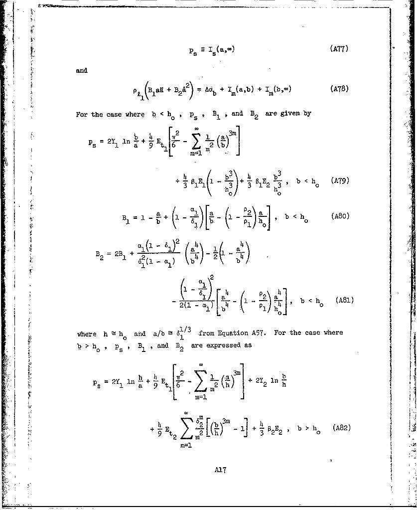
PS I (a,-) (A77)
and
I lar + B2 = Adb + Im(a,b) + (b,-) (A8)
For the case where b < h o , ps, B, and B2 are given by
4 O
b<h (AGO)
B. . + p 2 b <h (A8)
b+16)l( ) 7, 3h 3
2B + a 6 _ a-B2 =2 1 + ( bh! I
l a 2\ ap 4 ] b2<hh (A81)
4 0
where h adab from Equation A57. For the case where
h PS B, ,and B2 are expressed as
' + E 2 -3 b.
pe 2Y In +-4 2Y In-ia. a t 2 h-
icc2 t 2 - + L" 02E2 b >li (A82)
2 r 2).I;

- r2
a/ 12 P 2a bB, h h b- 0 " b>h (A83)
P~a29 -LO2 /a2
B-2B% + 2 . _
1 a
a[k Pk - ' 2 2b/ (a' (I:)-
where
h3 - a3 + (A85)
P1 o
2-2
_.~_.from Equation A63, and b is given by Equation A59. Note that at
matical treatment of~ the problem and does not necessarily correspond to
a physical discontinuity. What happens is that -at b = h , the speed at
-which the plastic fotis propagated undergoes a step change due to the
discontinuity in Y and E . This is an elastic effect and can occur
even if the materials are incompressible.
" Special Cases
15. When both layers have exactly the same properties (i.e. the '
homogeneous case), then by dropping the subscript, Equation A57 becomes
2"
p1 lb >1/ I (A84)
P1 E 2 1 m 2 0
: ~~3 Ps = -a3 n6 9 + 1 113 (A85) !
" m=l 1
P t 08
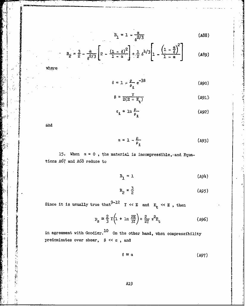
1 i1i
Bad (A88)
, 1 -2 - A?/3
B-1 = 3 + (A89)
where.
p~6 1 L e73 0 (A90)
" t
'1 0t =h - (A99)jP
1 1 (A93)
$ .s Ps-"f n3/ A6
15. When a Go0 ,the material is incompresib e,'and Equa-
tions A67 and A68 reduce to
B =1 (A94)
22 -(A95)
9-1
Since it is usually true that9 Y < E and Et < E ,then
p Y(1 + l2E)+ IT E (A96)
in agreement with Goodier. On the other hand, when compressibility
predominates over shear, 0 << a , and 'j 6 a (A97)

1/31B 1 -1 / (A98)
A
and
2 2 2A9
in agreement with Hanagud and Ross. 1
A20
APPENDIX B: COMPRESSIBILITY
. Introduction
p . The cavity expansion theory developed in Appendix A-and the
penetration theory developed in Part I! both utilize the concept of
lockigbehaviorl l ! 2 to estimate the effect of material compressibility
at any given instant. Moreover, within the context of the cavity expan-
sion theory and the present penetration theory, the incorporation of
compressibility constitutes a perturbation of the basic incompressible
theories set forth by Goodier. In this appendix a technique for
approximating the effective locking strain e is developed in, which
(I the material is first treated as incompressible in order to obtain an
approximate value for the average dynamic pressure in the plastic zone.
This pressure can then be used to estimate the average volumetric strain
; j (i.e., the effective locking strain eu) in the plastic zone when the
material is only slightly compressible.
Average Dynamic Pressure in the Plastic Zone
2. Suppose there is a spherical cavity centered at the origin
with radius a(t) , radial velocity A , and radial acceleration .
Furthermore, suppose that the cavity is surrounded by an incompressible
homogeneous material whose behavior in shear is rate independent. The
situation is spherically symmetric, and the dynamic pressure P at any
r > a in the material is2 2
=pr(ag + 2 2) a2 (Bl)
where r is the radial coordinate, p is density, and the material is
stress-free as r . The average value of P in a region a < r < b
is
Bi
L
P ave (B2)
] r? dr (2
Employing Equation BI in Equation B2 and evali atihg the integrals re-
sults in the expression
3 .
P p 3p (B3)ave 2 .t e
Suppose now that b represents the radius of the plastic front for an
incompressible elastic-plastic material as described in Appendix. A
(where p p£ ) such that Equations A86 and A90 reduce to
i a 61o/3 (B4)b, I
and
I = 1 - e-3 (B5)
Equation B4 is now incorporated in Equation B3 so the average dynamic
pressure in the plastic zone a < r < b for an incompressible material
is
(ad + 2A ) _ 12-_ h/3avP~ 3 I (B6)
Equation B6 can now be used in conjunction with a pressure-density curve
to obtain a first approximation to the averae volumetric strain (i.e.
locking strain) c£ in the plastic zone a < r < b as long as
Je«I << 1 . Thus, for materials which are only slightly compressible,
Equation B6 can be used to obtain a value for c which is appropriate
B2
-C
for the cavity expansion theory in Appendix A. For a two-layer situa-
tion, Equation B6 is used in turn for each layer. This may lead to an
underestimation of Jej for the first layer and an overestimation for
the second layer, but a reasonable approximation to the average effect
of compressibility for both layers is obtained.
Compressibility in the Penetration heory
1 3. An upper limit on P for projectile penetration is obtainedave
by replacing i with the projectile velocity 4 and dropping the mate-
rial acceleration term ad (Appendix C) in Equation B6 such that
.2 1I" ,.2 261/- 361 +
P ave 2 pq - 61
IEquation B7 can be used with a pressure-density curve for a given targetmaterial to obtain an upper limit on Ie£1 at any velocity 4 as long
as l 1 . Subject to this limitation,
a =1-c (B8)
B3I;
~,
S ;'
APPENDIX C: TARGET ACCELERATION
Introduction
1. In Goodier's original penetration theory for rigid spherical.9,10
projectiles, the projectile equation of motion is
23 Bs 3p = (Cl)(M aira p 1 _7r 0p + a Z2
The development of this equation is discussed in Part II, paragraph 9.The term (2/3)a3p B 1 reflects Goodier's assumed variation of target
acceleration over the frontal surface of the projectile, and the quantity
13(2/3)Ta-p' is generally known as the added mass for the sphere. When
R << 1 (Part II, Equation 5), this term has only a small effect on
penetration depth predictions; but when the added mass is comparable to
projectile mass M (e.g., Ra Z 0.1), then the effect of this terma i
becomes significant.
The Effect of Added Mass on Penetration Predictions
2. Consider the projectile equation of motion (Cl) which withoutthe term (2/3)ffaoPB 1 reduces to Ji
M= + q (02)
where deletion of the added mass is tantamount to disregarding target ac-
celeration. Equation 02 is now used in Goodier's original applications
of his rigid projectile penetration theory. The results are shown in
Figures Cl-C4; the solid curves correspond to Equation Cl, and the dashed
- curves correspond to Equation 02. In these figures q is final pene-
tration depth, D is projectile diameter, v ° is impact velocity, p
is projectile density, and Y is target yield strength. In each case
discarding the added mass term improves agreement with experiment. From
these results it is concluded that the contribution of the term ra3 pB 1
Cl
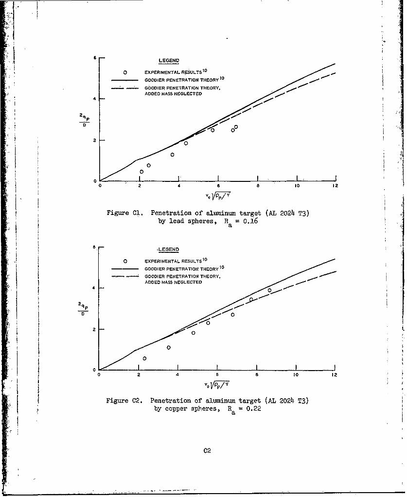
0 EXPERIMENTAL RESULTS 10
-- GOODIER PENETRATION THEORY,1
4
01
D 2
:1.0 00
0 2 4 a 8 10 12
v YP/Y
Figure Cl. Penetration of' aluminum target (AL 2024~ T3)by lead spheres, R a =oAi6
S ~LEGEND
o EXPERIMENTAL RESULTS 10
GOODIER PENETRATION THEORY0
4 - GOODIER PENETRATION THEORY,ADDED MASS NEGLECTED
2q P
00
2
00 z 2 IA I I Ji0 6 8 10 12
.11 ~Figure 02. Penetration of' aluminum target (AL 2024~ T3)by copper spheres, Ra 0.22
C2

LEGEND
0 XEIETAL RESULTS1
GOODIER PENETRATION THEORY 10
4 - - GOODICR PENETRATION THEORY.
1 ADDED MASS NEGLECTED
2qP
D P
~0
v IPI J i
J Figure 03. Penetration of alumninum target (AL 2024i T3)by steel spheres, R a =0.25
8 LEGEND
0 EXPERIMENTAL RESULTS 10
2~ fGOODIER PENETRATION THEORY 0
- -- G0061ER PENETRATION THEORY,ADODOMASS NEGLECTED
00
00
00 2 4 6 8 0 12
Figure C4i. Penetration of aluaminum target (AL 2024i T3)by aluminum spheres, R a 0.75
C3

whj.h appears in Part !I, Equation 30 and elsewhere, probably represents
a high upper limit insofar as the effect of target acceleration on final
depth of penetration is concerned. Furthermore, for most applications
of the penetration theory as formulated, it appears appropriate simply
to drop the B1 term from Equation 30. However, this term is retainedas an upper limit for added mass throughout the presentation of theory
in Part II.
<c4
.,bCl.

APPENDIX D: NOTATION
a,a,a Radial position, velocity, and acceleration of spherical cavitywall, respectively
a, Projectile radius-at point of contact with a layerginterfacea n Projectile radius at point of contact with the target surfacen
a Projectile radius at base of noseo 2
A Projectile frontal -area = ffa0
b,h Radii of spherical plastic front and concentric layer inter-face, respectively
B1,B2 Inertial coefficients from cavity expansion theory
C Initial sound speed0
CG Center of gravity
CRH Ogive caliber radius head
D Projectile diameter at base of nose = 2a0
E Modulus of elasticity
Et Strain-hardening modulus
f Factor relating projectile nose shape to target inertialn resistance
Fx Resisting force projected normal to projectile axis of symmetry
F Resisting force projected along projectile axis of symmetryz
G Ratio of maximum inertial resistance to shear resistance within0 the context of penetration theory-- (PB 2
2/ps)H Layer interface locationH 0 Initial layer interface location
I Projectile moment of inertia
I Momentum integralm
I General shear integrals
L Nose length
M Projectile mass
MCG Moment about CG
p Compressive normal stress on projectile surface
Pn Average value of p over the projectile nose surface
Ps Component of p due to target deformation (shear resistance)
Pl Component of p due to target inertia (dynamic pressure)
Dl

Pave Average-dynamic pressure in the plastic zone,
qi2,q Projectile, penetration depth, velocity,, andacCeleration,respectively
qp Final depth of pendtratibn
• pt Final penetration ,depth for a blunt cylinder
q. Projectile penetration depth when the-pIastic front reachesa
layer interface3,
Ha 7a p /M added mass parametera 0
R Nose performance ration 2
H pq /Y , order of magnitude index of the ratio of inertia forcess to shear forces, referred to as-the "solid Reynolds number"
S Location of plastic front
t Time
v Radial velocity in the elastic region
vA Radial velocity in the plastic region
vn Normal component of particle'velocity
v Impact velocity0v Target particle velocityP
vt Tangential component of particle velocity
W Projectile weight
XYZ Fixed space coordinates
Y Yield strength
z Distance from projectile nose tip along axis of symmetry
z G Distance from projectile nose tip to CG
z Point where the projectile axis of symmetry intersects thetarget surface
a Target compressibility =1- p/pt
0 Y12/(E - E)
y Moment arm
8 1 - (p/p/) exp (-30)
C Locking strain = ln (p/ps)
S Radial strainrs8 Tangential strain
4 LID
0 Polar coordinate or polar angle
D2

Ix See Equation 78
S Z/Z
.r 3.1416
p Initial target density
p Locked target density, i.e., average COmpressed density in" theplastic zoneLimiting Value of a as r + b in the elastic region
a(-) Limiting value of & as r + b in the locked plastic regionb rZ Radial stressr
a6 Circumferential stress
0 Cone half-angle
PCircumscribed cone half-angle
W,w,W Angle of obliquity, rotational velocity, and angular accelera-tion, respectively
w m Initial angle of obliquity0
Note: A dot over any quantity denotes a derivative with respect to time.
D3
_ _ _ ___ _ _ _ _ __ _ _ _ _ _

In acowdmce with ER 70-2-3, Vuvrpa*k 6c(l)(b),aat.4 15 ?ebru=a7 1973, a fieslailo catalog caa-dIn Libr of Congress format is r~vmfte~d below.
Bernard, Robert SDevelopment of a projectile penetration theory; Report 1.:
Penetration theory for shallow to moderate depths, by RobertS. Bernard oand: Sathya V. Hanagud. Vicksburg, U. S. ArmyEngineer Waterways Experiment Station, 1975.1 v. (various pagings) illus. 27 cm. (U. S. Waterways
* - Experiment Station. Technical report S-75-9, Report 1)Prepared for Office, Chief of Engineers, U. S. Army,
Washington, D. C., under Project 4Al6ll02B52E, Task 04,Work Unit 013.
Includes bibliography.
1. Projectile penetration. I. Hanagud, Sathya V., jointauthor. II. U. S. Army. Corps of Engineers. (Series:U. S. Waterways Experiment Station, Vicks~burg, Miss.Technical rqjort S-75-9, Report 1)TA7.W34 no.S-75-9 Report 1


