
p. 1DSP-II
Digital Signal Processing II
Lecture 7: Modulated Filter Banks
Marc Moonen
Dept. E.E./ESAT, K.U.Leuven
homes.esat.kuleuven.be/~moonen/

DSP-IIVersion 2006-2007 Lecture-7 Modulated Filter Banks p. 2
Part-II : Filter Banks
: Preliminaries• Applications
• Intro perfect reconstruction filter banks (PR FBs)
: Maximally decimated FBs• Multi-rate systems review
• PR FBs
• Paraunitary PR FBs
: Modulated FBs• DFT-modulated FBs
• Cosine-modulated FBs
: Special Topics• Non-uniform FBs & Wavelets
• Oversampled DFT-modulated FBs
• Frequency domain filtering
Lecture-5
Lecture-6
Lecture-7
Lecture-8

DSP-IIVersion 2006-2007 Lecture-7 Modulated Filter Banks p. 3
Refresh
General `subband processing’ set-up (Lecture-5) :
- analysis bank+ synthesis bank
- multi-rate structure: down-sampling after analysis, up-sampling for synthesis
- aliasing vs. ``perfect reconstruction”
- applications: coding, (adaptive) filtering, transmultiplexers
- PS: subband processing ignored in filter bank design
subband processing 3H0(z)
subband processing 3H1(z)
subband processing 3H2(z)
3
3
3
3 subband processing 3H3(z)
IN
F0(z)
F1(z)
F2(z)
F3(z)
+
OUT

DSP-IIVersion 2006-2007 Lecture-7 Modulated Filter Banks p. 4
Refresh
Two design issues : - filter specifications, e.g. stopband attenuation, passband ripple, transition
band, etc. (for each (analysis) filter!)
- perfect reconstruction property (Lecture-6).
PS: Lecture 6/7 = maximally decimated FB’s = NM
4444
+u[k-3]
1z
2z
3z
1
1z2z3z
1
u[k] 444
4)(zE )(zR
NIzz )().( ER

DSP-IIVersion 2006-2007 Lecture-7 Modulated Filter Banks p. 5
Introduction
-All design procedures so far involve monitoring of characteristics (passband ripple, stopband suppression,…) of all (analysis) filters, which may be tedious.
-Design complexity may be reduced through usage of `uniform’ and `modulated’ filter banks.
• DFT-modulated FBs • Cosine-modulated FBs
DSP-IIVersion 2006-2007 Lecture-7 Modulated Filter Banks p. 6
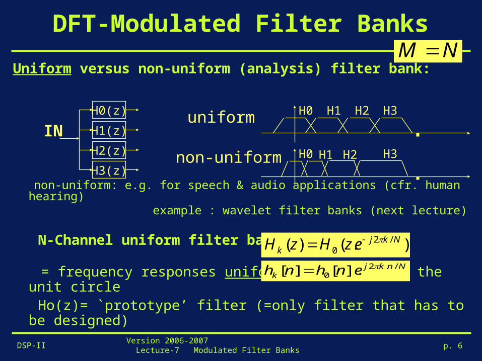
DFT-Modulated Filter Banks
Uniform versus non-uniform (analysis) filter bank:
non-uniform: e.g. for speech & audio applications (cfr. human hearing) example : wavelet filter banks (next lecture)
N-Channel uniform filter bank:
= frequency responses uniformly shifted over the unit circle
Ho(z)= `prototype’ filter (=only filter that has to be designed)
H0(z)
H1(z)
H2(z)
H3(z)
INH0 H3H2H1
H0 H3H2H1uniform
non-uniform
).()( /20
Nkjk ezHzH
NM
Nnkjk enhnh /.2
0 ].[][

DSP-IIVersion 2006-2007 Lecture-7 Modulated Filter Banks p. 7
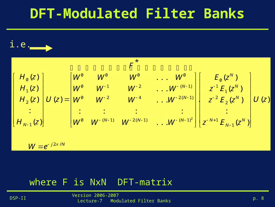
DFT-Modulated Filter Banks
Uniform filter banks can be implemented cheaply based
on polyphase decompositions + DFT(FFT)
hence named `DFT modulated FBs’
1. Analysis FB
If
then
).()( with )(),...,(),( /20110
NkjkN ezHzHzHzHzH
with , )(..
)(..).()(
/21
0
1
0
1
/2/2/20
NjN
l
Nl
kll
N
l
NkNjNl
NkljlNkjk
eWzEWz
ezEezezHzH
)(.)(1
00
N
l
Nl
l zEzzH
i.e.
H0(z)
H1(z)
H2(z)
H3(z)
u[k]
DSP-IIVersion 2006-2007 Lecture-7 Modulated Filter Banks p. 8
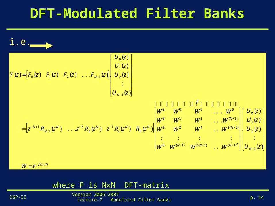
DFT-Modulated Filter Banks
where F is NxN DFT-matrix
Nj
NN
N
N
N
N
NNN
N
N
N
eW
zU
zEz
zEz
zEz
zE
F
WWWW
WWWW
WWWW
WWWW
zU
zH
zH
zH
zH
/2
11
22
11
0
)1()1(2)1(0
)1(2420
)1(210
0000
1
2
1
0
)(.
)(.
:
)(.
)(.
)(
.
*
...
::::
...
...
...
)(.
)(
:
)(
)(
)(
2
i.e.

DSP-IIVersion 2006-2007 Lecture-7 Modulated Filter Banks p. 9
DFT-Modulated Filter Banks
conclusion: economy in… - implementation complexity: N filters for the price of 1, plus DFT (=FFT) ! - design complexity: design `prototype’ Ho(z), then other Hi(z)’s are automatically `co-designed’ (same passband ripple, etc…) !
*F
u[k]
)( 40 zE
)( 41 zE
)( 42 zE
)( 43 zE
)(0 zH
)(1 zH
)(2 zH
)(3 zH
i.e.
DSP-IIVersion 2006-2007 Lecture-7 Modulated Filter Banks p. 10
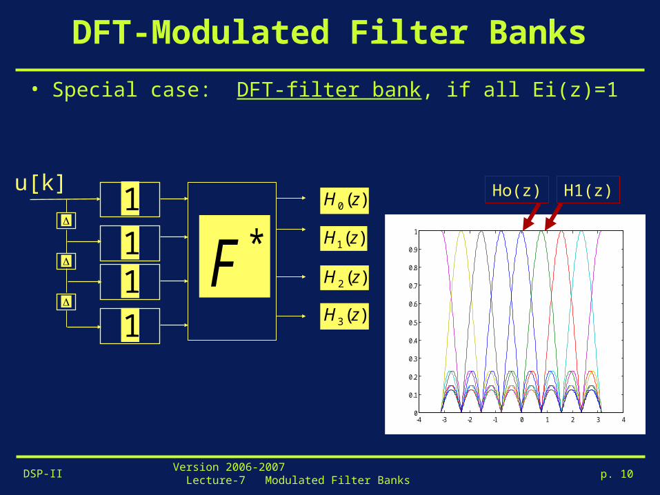
DFT-Modulated Filter Banks
• Special case: DFT-filter bank, if all Ei(z)=1
*F
u[k]
1 )(0 zH
)(1 zH
)(2 zH
)(3 zH
11
1
-4 -3 -2 -1 0 1 2 3 40
0.1
0.2
0.3
0.4
0.5
0.6
0.7
0.8
0.9
1
Ho(z) H1(z)
DSP-IIVersion 2006-2007 Lecture-7 Modulated Filter Banks p. 11
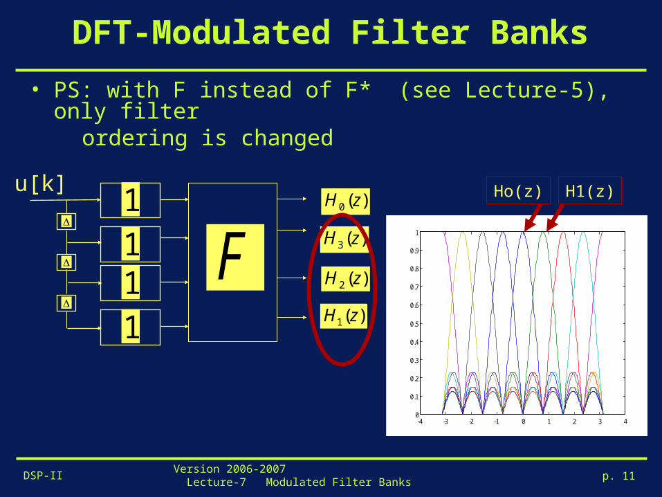
DFT-Modulated Filter Banks
• PS: with F instead of F* (see Lecture-5), only filter ordering is changed
-4 -3 -2 -1 0 1 2 3 40
0.1
0.2
0.3
0.4
0.5
0.6
0.7
0.8
0.9
1
Ho(z) H1(z)
Fu[k]
1 )(0 zH
)(1 zH
)(2 zH
)(3 zH11
1

DSP-IIVersion 2006-2007 Lecture-7 Modulated Filter Banks p. 12
DFT-Modulated Filter Banks
• Uniform DFT-modulated analysis FB +decimation (M=N)
*F 4
4
4
4u[k]
)( 40 zE
)( 41 zE
)( 42 zE
)( 43 zE
4
4
4
4u[k]
*F)(0 zE
)(1 zE
)(2 zE
)(3 zE
=

DSP-IIVersion 2006-2007 Lecture-7 Modulated Filter Banks p. 13
DFT-Modulated Filter Banks
2. Synthesis FB
).(.)( with )(),...,(),( /20
/2110
NkjNkjkN ezFezFzFzFzF
)(.)(1
00
N
l
Nl
l zRzzF )(..... )(1
0
)1(
N
l
Nl
lNklk zRWzzF
+
+
+
)(0 zF][0 ku
)(1 zF][1 ku
)(2 zF][2 ku
)(3 zF][3 kuy[k]
phase shift added
for convenience
DSP-IIVersion 2006-2007 Lecture-7 Modulated Filter Banks p. 14
DFT-Modulated Filter Banks
where F is NxN DFT-matrix
Nj
NNNN
N
N
NNNNN
N
N
N
eW
zU
zU
zU
zU
F
WWWW
WWWW
WWWW
WWWW
zRzRzzRzzRz
zU
zU
zU
zU
zFzFzFzFzY
/2
1
2
1
0
)1()1(2)1(0
)1(2420
)1(210
0000
011
22
11
1
2
1
0
1210
)(
:
)(
)(
)(
.
...
::::
...
...
...
.)()(.)(....)(.
)(
:
)(
)(
)(
.)(...)()()()(
2
i.e.

DSP-IIVersion 2006-2007 Lecture-7 Modulated Filter Banks p. 15
DFT-Modulated Filter Banks
y[k]
+
+
+)( 40 zR
)( 41 zR
)( 42 zR
)( 43 zR][0 ku
][1 ku
][2 ku
][3 ku
F
i.e.
DSP-IIVersion 2006-2007 Lecture-7 Modulated Filter Banks p. 16
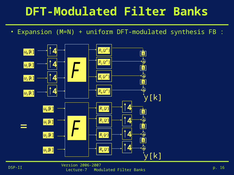
DFT-Modulated Filter Banks
• Expansion (M=N) + uniform DFT-modulated synthesis FB :
y[k]
4
4
4
4
+
+
+)(0 zR
)(1 zR
)(2 zR
)(3 zR][0 ku
][1 ku
][2 ku
][3 ku
F
y[k]
+
+
+
4
4
4
4 )( 40 zR
)( 41 zR
)( 42 zR
)( 43 zR][0 ku
][1 ku
][2 ku
][3 ku
F
=

DSP-IIVersion 2006-2007 Lecture-7 Modulated Filter Banks p. 17
DFT-Modulated Filter Banks
Perfect reconstruction (PR) revisited :maximally decimated (M=N) uniform DFT-modulated analysis & synthesis…
- Procedure:
1. Design prototype analysis filter Ho(z) (=DSP-II/Part-I).
2. This determines Ei(z) (=polyphase components).
3. Assuming Ei(z) can be inverted (?), choose synthesis filters
y[k]
4444
+
+
+)(0 zR
)(1 zR
)(2 zR
)(3 zR
F444
4u[k]
*F)(0 zE
)(1 zE
)(2 zE
)(3 zE
)()( 11 zEzR lNl
FERFE .)()()( )(.)( 11* zEdiagzzzEdiagz ii

DSP-IIVersion 2006-2007 Lecture-7 Modulated Filter Banks p. 18
DFT-Modulated Filter Banks
Perfect reconstruction (PR):
FIR E(z) generally leads to IIR R(z), where stability is a concern…
PR with FIR analysis/synthesis bank (=guaranteed stability), only
obtained with trivial choices for Ei(z)’s (next slide)
y[k]
4444
+
+
+)(0 zR
)(1 zR
)(2 zR
)(3 zR
F444
4u[k]
*F)(0 zE
)(1 zE
)(2 zE
)(3 zE
)()( 11 zEzR lNl

DSP-IIVersion 2006-2007 Lecture-7 Modulated Filter Banks p. 19
DFT-Modulated Filter Banks
• Simple example (1) is , which leads to IDFT/DFT bank (Lecture-5)
i.e. Fl(z) has coefficients of Hl(z), but complex conjugated and in reverse order (hence same magnitude response) (remember this?!)
• Simple example (2) is , where wi’s are constants, which leads to `windowed’ IDFT/DFT bank, a.k.a. `short- time Fourier transform’ (see Lecture-8)
• Question (try to answer): when is maximally decimated PR uniform DFT-modulated FB - FIR (both analysis & synthesis) ? - paraunitary ?
1)()( zEzR ll
)1()1(33221 .......1)( NlNllll zWzWzWzWzH
)1()2()3(2)4(3)1( ......)( NNlNlNllNl zzWzWzWWzF
11 )()( ilNil wzRwzE
DSP-IIVersion 2006-2007 Lecture-7 Modulated Filter Banks p. 20
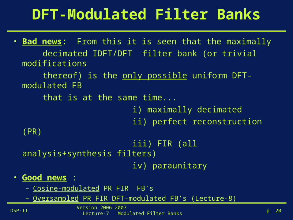
DFT-Modulated Filter Banks
• Bad news: From this it is seen that the maximally
decimated IDFT/DFT filter bank (or trivial modifications
thereof) is the only possible uniform DFT-modulated FB
that is at the same time...
i) maximally decimated
ii) perfect reconstruction (PR)
iii) FIR (all analysis+synthesis filters)
iv) paraunitary• Good news :
– Cosine-modulated PR FIR FB’s – Oversampled PR FIR DFT-modulated FB’s (Lecture-8)

DSP-IIVersion 2006-2007 Lecture-7 Modulated Filter Banks p. 21
Cosine-Modulated Filter Banks
• Uniform DFT-modulated filter banks: Ho(z) is prototype lowpass filter, cutoff at for N filters
• Cosine-modulated filter banks :
Po(z) is prototype lowpass filter, cutoff at for N filters
Then...
etc...
N/
N2/
H0 H3H2H1
2N/
).(.).(.)()5.0(
0*0
)5.0(
000N
jN
jezPezPzH
P0
2
2
2
N2/
N/H1
Ho
).(.).(.)()5.01(
0*1
)5.01(
011N
jN
jezPezPzH
).()( /20
Nkjk ezHzH

DSP-IIVersion 2006-2007 Lecture-7 Modulated Filter Banks p. 22
Cosine-Modulated Filter Banks
• Cosine-modulated filter banks : - if Po(z) is prototype lowpass filter designed with real coefficients po[n], n=0,1,…,L then
i.e. `cosine modulation’ (with real coefficients) instead of `exponential modulation’ (for DFT-modulated bank, see page 6)
- if Po(z) is `good’ lowpass filter, then Hk(z)’s are `good’ bandpass filters
).(.).(.)()5.0(
0*)5.0(
0N
kj
kN
kj
kk ezPezPzH
}4
.)1()2
)(5.0(cos{].[.2][ 0
kk
Lnk
Nnpnh

DSP-IIVersion 2006-2007 Lecture-7 Modulated Filter Banks p. 23
Cosine-Modulated Filter Banks
Realization based on polyphase decomposition (analysis):
- if Po(z) has 2N-fold polyphase expansion (ps: 2N-fold for N filters!!!)
then...
k
kl
N
l
Nl
lL
k
k zlkNpzEzEzzkpzP ]..2[)( , )(.].[)( 0
12
0
2
000
NNT 2
u[k]
)( 20
NzE
)( 21
NzE
)( 212
NN zE
)(0 zH
)(1 zH
)(1 zH N
: :
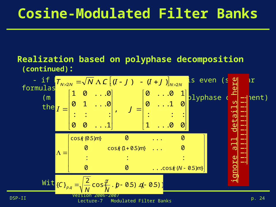
DSP-IIVersion 2006-2007 Lecture-7 Modulated Filter Banks p. 24
Cosine-Modulated Filter Banks
Realization based on polyphase decomposition (continued):
- if Po(z) has L+1=m.2N taps, and m is even (similar formulas for m odd) (m is the number of taps in each polyphase component) then...
With
00...1
:::
01...0
10...0
,
1...00
:::
0...10
0...01
)()(... 22
JI
JIJICNT NNNN
})5.0(cos{
})5.01(cos{
})5.0(cos{
...00
:::
0...0
0...0
mN
m
m
)}5.0).(5.0.(cos{2
}{ , qpNN
C qp
ign
ore
all
det
ails
h
ere
!!!!!
!!!!!!
!!!!

DSP-IIVersion 2006-2007 Lecture-7 Modulated Filter Banks p. 25
Cosine-Modulated Filter Banks
Realization based on polyphase decomposition (continued): - Note that C is NxN DCT-matrix (`Type 4’)
hence fast implementation (=fast matrix-vector product) based on fast discrete cosine transform procedure, complexity O(N.logN). - Modulated filter bank gives economy in * design (only prototype Po(z) ) * implementation (prototype + modulation (DCT))
Similar structure for synthesis bank
)}5.0).(5.0.(cos{2
}{ , qpNN
C qp
NNT 2
u[k]
)( 20
NzE
)( 21
NzE
)( 212
NN zE
)(0 zH
)(1 zH
)(1 zH N
: :

DSP-IIVersion 2006-2007 Lecture-7 Modulated Filter Banks p. 26
Cosine-Modulated Filter Banks
Maximally decimated cosine modulated (analysis) bank :
NNT 2
u[k]
)( 20
NzE
)( 21
NzE
)( 212
NN zE
:
N
N
N
NNT 2
u[k]
)( 20 zE
)( 21 zE
)( 212 zE N
:
N
N
N=
DSP-IIVersion 2006-2007 Lecture-7 Modulated Filter Banks p. 27
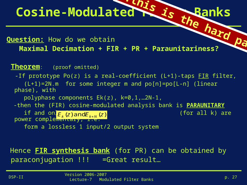
Cosine-Modulated Filter Banks
Question: How do we obtain Maximal Decimation + FIR + PR + Paraunitariness?
Theorem: (proof omitted)
-If prototype Po(z) is a real-coefficient (L+1)-taps FIR filter, (L+1)=2N.m for some integer m and po[n]=po[L-n] (linear phase), with polyphase components Ek(z), k=0,1,…2N-1, -then the (FIR) cosine-modulated analysis bank is PARAUNITARY if and only if (for all k) are power complementary, i.e. form a lossless 1 input/2 output system
Hence FIR synthesis bank (for PR) can be obtained by paraconjugation !!! =Great result…
)( and )( zEzE Nkk
..this is the hard part…

DSP-IIVersion 2006-2007 Lecture-7 Modulated Filter Banks p. 28
Cosine-Modulated Filter Banks
Perfect Reconstruction (continued)
Design procedure: Parameterize lossless systems for k=0,1..,N-1 Optimize all parameters in this parametrization so that the prototype Po(z) based on these polyphase components is a linear-phase lowpass filter
that satisfies the given specifications
Example parameterization: Parameterize lossless systems for k=0,1..,N-1, -> lattice structure (see Part-I), where parameters are rotation angles
)( and )( zEzE Nkk
)(zEk
)(zE Nk
kl
kl
kl
klk
l
kkkm
km
Nk
k
zzzzE
zE
cossin
sincos
0
1..
0
01....
0
01..
0
01.
)(
)(0111211
E
EEEE
)( and )( zEzE Nkk
..this is the hard part…

DSP-IIVersion 2006-2007 Lecture-7 Modulated Filter Banks p. 29
Cosine-Modulated Filter Banks
PS: Linear phase property for po[n] implies that only half of the power
complementary pairs have to be designed. The other pairs are then
defined by symmetry properties.
NNT 2
u[k]
:
N
Np.26 = )( 20 zE
)( 2zEN
)( 21 zEN
)( 212 zE N
:
:
lossless

DSP-IIVersion 2006-2007 Lecture-7 Modulated Filter Banks p. 30
Cosine-Modulated Filter Banks
PS: Cosine versus DFT modulation In a maximally decimated cosine-modulated (analysis) filter bank 2 polyphase components of the prototype filter, ,
actually take the place of only 1 polyphase component in the DFT- modulated case. For paraunitariness (hence FIR-PR) in a cosine-modulated bank, each such pair of polyphase filters should form a power complementary pair, i.e. represent a lossless system.
In the DFT-modulated case, imposing paraunitariness is equivalent to imposing losslessness for each polyphase component separately, i.e. each polyphase component should be an `allpass’ transfer function. Allpass functions are always IIR, except for trivial cases (pure delays). Hence all FIR paraunitary DFT-modulated banks (with maximal decimation) are trivial modifications of the DFT bank.
)( and )( zEzE Nkk
no FIR-design flexibility
provides flexibility for FIR-design


