Download - Digital Signal Processing Lecture 1

Dr. Shoab Khan
Digital Signal Processing
Lecture 1
Introduction
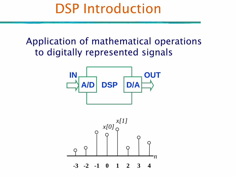
DSP Introduction
Application of mathematical operations to digitally represented signals
IN OUT
A/D D/ADSP
-3 -2 -1 0 1 2 3 4
x[0]x[1]
n

General IntroductionDiscrete Time Signal
sequence x[n]
- as opposed to continuous-time signals x(t)
- “time” = independent variable

ExamplesDiscrete in Nature
- stock market indices
NasDaq daily closing value from Aug 1995 to Jan 1996
- population statistics
Birth in Canada from 1995-1996 to 1999-2000

Example
Sampled continuous-time (analog) signals
- Speech

Digital Images
2-D arrays (matrices) of numbers

Typical DSP Applications
Digital
RadiographicImaging
Ultrasound MedicalImaging
Spy SatelliteImagingMilitaryAppls
Real Time Video Cameras
& Cell Phones
VideoCommunications
Space
Imaging
Appls
Optical Wearable Computers
Web wirelesstechnologyData Storage
& Transmission
Car Awake warning system
Real
Time DSP
Embedded Systems
Speech
Recognition

Example: Speech Modeling
Impulse
Train
Generator
Noise
Generator
Pitch
Period
×u(n)
Time-
varying
digital
filter
Vocal Tract
Parameters
s(n)
G

An Embedded System
Control Panel
PROGRAMMABLE
DSP
PROGRAMMABLE
DSP
ASIC
FPGA
MICROCONTROLLER
CODEC
Dual Port Memeory
System Bus
Controller Process
User interface
process
DSP
Assembly
Code
Analog
interface
Real Time
Operating
system
Embedded signal
Processing System
Host port
Memory interface
Host port
Memory interface

Example Embedded System
Output
Bitstream
49.152
MHz
Sine wave
clock
Xilinx 4062TMS320C6201
68332
SRAM
FLASH
SBSRAM
DDS
A/D
HSP52014
8-bit DAC &LPF
amplifier &squarer
I/Osquare waveoutput
To RF Board
From RF Board

SDR Board Design
FPGA
SPARTAN3
XC3S1500FG676I
- XC3S2000FG676I
VCCINT=1.2V/470mA
VCCAUX=2.5V/100mA
VCCO1=3.3V/mA
VCCO2=2.5V/mA
AD9640
DUAL ADC
14BIT, 105 MSPS
AVDD=1.8V/310mA
DVDD=1.8V/34mA
DRVDD=3.3V/35mA
GC5016
Quad Wideband DUC/DDC
VPAD=3.3V/180mA
VCORE=1.8V/420mA
DUAL Channel
14 bit ,
125 MSPS (Max)
DAC,
DAC2904,
VA=3.3V/64mA
VD=3.3V/19.5mA
RS232 Interface DB9
DSP
TMS320DM6446
CVDD 1.2V/767mA
DVDD 1.8V/102mA
DVDD 3.3V/6mA
32
47
IN
AD8352
Differential
Amp
AMP
FILTER
NETWORK
Not
implemente
d
IN
POWER
IN
HPI / VLYNQ
interface
LVCMOS_1.8V
32BIT
JTAG
Title: Tranceiver Board
Size: A Revision: 1.3
Date: 08/04/08 Drawn by: ASK
RSSI
Analog
Interface
8 Channel ADC
MCP3008
VD=3.3V/0.5mA
4-Bit
RS232 TRANSCEIVER
MAX3232EID
I-Input
Q-Input
I-Output
Q-Output
16
7
Clock
Generator
AD9513
3 outputs
GAIN CONTROL (6-BIT)
PA
interface6-Bits Output power control
Filter
Selection3-Bit Rx Filter Selection
HMC610
RSSI
x2
1-Bit T/R Control
5-Bit Frequency controlSythesizer
Interface
T/R Switch
/2
2x MT47H64M16BT-5E
1G DDR SDRAM
64M x 32
1.8VD/mA?
OSC
Ethernet
Interface
RJ45
Ethernet PHY
DP83848I
IOVDD=3.3V/150mA
AVDD=3.3V/100mA?
20
Digital Power
(SMPS)
1.2VD
1.8VD
2.5VD
3.3VD
Analog
(LDO Linear PSU)
1.8VA
3.3VA
PLATFORM
FLASH
XCF08P 3.3VD/20mA
28F256J3, 128Mb
16MB Intel Strata flash
3.3V/80mA
JTAGEXP
HEADER16-32 IO
64-LFCSP_VQ
SOIC-16
TQFP-48
PBGA-252
FG-676 (BGA) FSG-48 (BGA)
PBGA-N361
LQFP-48
SPI
IN
IN
IN
16-LFCSP_VQ
SOIC-16
Spartan3
SUPPORTS
LVCMOS-1.8
AUDIO SERIAL PORT
ASP HEADER
SSN
Silicon Serial Number

Device 0
DataData
Waveform 1
Software Defined RadioAll configurable HW
FPGA
Device 4
Device 1
DSP
General Purpose Processor
Algo4 Proprietary
½ FEC
Framer 1 V.3516
QAMOFDM
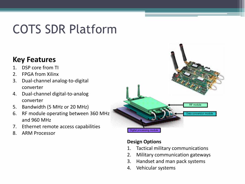
COTS SDR Platform
Key Features1. DSP core from TI2. FPGA from Xilinx 3. Dual-channel analog-to-digital
converter4. Dual-channel digital-to-analog
converter 5. Bandwidth (5 MHz or 20 MHz) 6. RF module operating between 360 MHz
and 960 MHz 7. Ethernet remote access capabilities8. ARM Processor
Design Options1. Tactical military communications2. Military communication gateways3. Handset and man pack systems 4. Vehicular systems

Course Objectives
To establish the idea of using computing techniques to alter the properties of a signal for desired effects, via understanding of Fundamentals of discrete-time, linear, shift-
invariant signals and systems in Representation and Analysis: sampling, quantization,
Fourier and z-transform;
Implementation: filtering and transform techniques;
System Design: filter & processing algorithm design.
Efficient computational algorithms and their implementation.

Course Outline

Course Outline

Prerequisite
A fundamental course in signal and system
Liner System analysis and transform analysis
convolution and filtering
Fourier transforms
Laplace and z transforms

Textbook
Oppenheim, Schafer and Buck, Discrete-Time Signal Processing, 2nd edition (Prentice-Hall, 1999)
Refrences: McClellan, Schafer, &
Yoder, DSP First
Ifeachor Jervis “Digital Signal Processing- A Practical Approach”, Prentice Hall

Historical Perspective
Who is who of DSP

Cooley and Tuckey


Inventors: Oppenhiam, Schaffer ...

Inventors: Parks & McCllelan

Inventors: Gold and Rader
Inventor: J. Kaiser

Inventor: Haskell

Original Speech
Analysis:
• Voiced/Unvoiced decision
• Pitch Period (voiced only)
• Signal power (Gain)
G
Pulse Train
Random Noise
Vocal Tract
Model
V/U
Synthesized Speech
DecoderSignal Power
Pitch
Period
Encoder
Linear Predictive Coding

Inventor: James G. Dunn

DSP Components

Signals
Basic Types

Basic Types of Digital SignalsBasic Types of Digital Signals

sindemo
Basic Types of Digital Signals

Sine and Exp Using Matlab
% sine generation: A*sin(omega*n+theta)
% exponential generation: A^n
n = 0: 1: 50;
% amplitude
A = 0.87;
% phase
theta = 0.4;
% frequency
omega = 2*pi / 20;
% sin generation
xn1 = A*sin(omega*n+theta);
% exp generation
xn2 = A.^n;

operations
Basic Operations
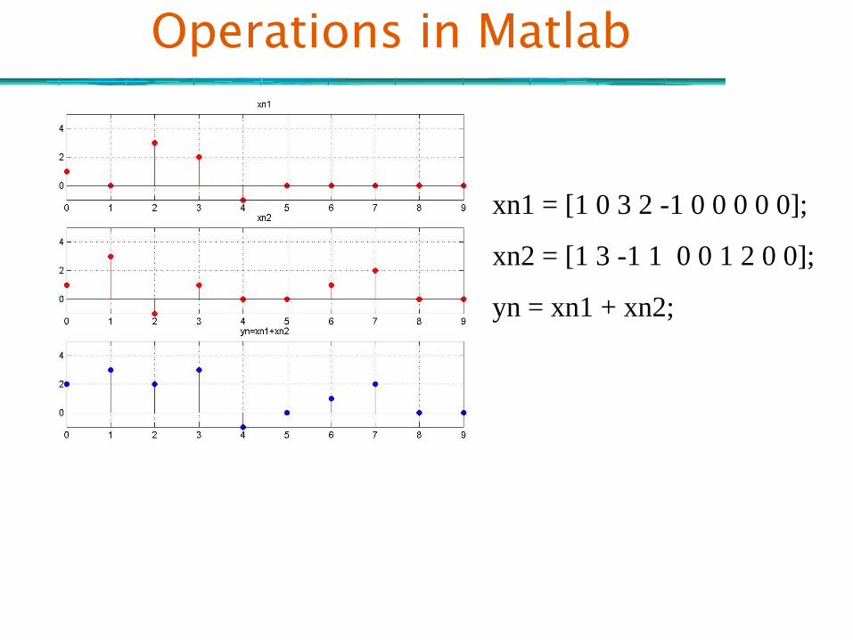
Operations in Matlab
xn1 = [1 0 3 2 -1 0 0 0 0 0];
xn2 = [1 3 -1 1 0 0 1 2 0 0];
yn = xn1 + xn2;


