Controls and Dynamics Technology Branch at Lewis FieldGlenn Research Center
Distributed Engine Control
Workshop at Ohio Aerospace Institute, Cleveland OHNov. 6-7, 2007
Dennis CulleyPh: (216) 433-3797
email: [email protected]://www.lerc.nasa.gov/WWW/cdtb
at Lewis Field2Glenn Research Center
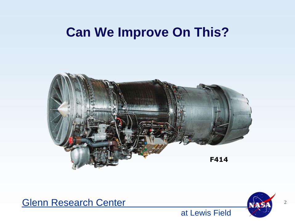
Can We Improve On This?
F414
at Lewis Field3Glenn Research Center
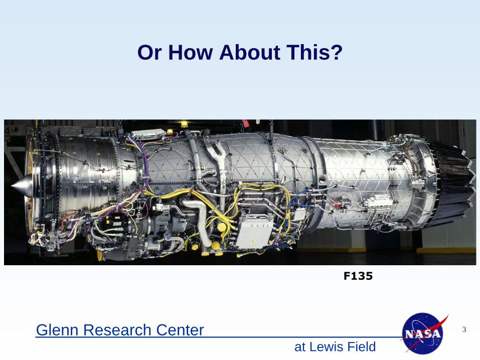
Or How About This?
F135
at Lewis Field4Glenn Research Center
Outline
• Team Members• Focus & Expectations for Distributed Engine Control• Overview of Distributed Engine Control Architecture• Challenges of Distributed Engine Control • NASA Task Plan Details
– Architecture– Subsystems– High Temperature Electronics
at Lewis Field5Glenn Research Center
Team MembersDennis Culley Controls & Dynamics (RIC)Randy Thomas Controls & Dynamics (RIC)Joseph Saus Controls & Dynamics (RIC)Michael Krasowski Optical Instrumentation and NDE (RIO)Lawrence Greer Optical Instrumentation and NDE (RIO)Norman Prokop Optical Instrumentation and NDE (RIO)Glenn Beheim Sensors and Electronics (RIS)Laura Evans Sensors and Electronics (RIS)Philip Neudeck Sensors and Electronics (RIS)Richard Patterson Space Environmental Durability (RPY)Kue Chun Digital Communications (RCD)Joseph Flatico Ohio Aerospace Institute (OAI)Andrew Trunek Ohio Aerospace Institute (OAI)David Spry Ohio Aerospace Institute (OAI)Carl Chang Arctic Slope Regional Corp (ASRC)
at Lewis Field6Glenn Research Center
Enabling
advanced aircraft configurations such as “Blended Wing Body (BWB),” “Extreme Short Take Off and Landing (ESTOL)” and high performance “Intelligent Engines”
will require advancement in the state of the art of dynamic modeling and flight/propulsion control. Control methods need to be developed and validated for “optimal” and reliable performance of complex, unsteady, and nonlinear systems with significant modeling uncertainties. The emphasis will be on developing technologies for
improved aircraft performance, enabling robust control of unconventional configurations, and active control of components for improved propulsion efficiency and lower emissions.
SFW.2.08—Controls and Dynamics
For enabling “Intelligent Engines,” the focus will be on developing technologies for enabling distributed engine control to reduce overall controls and accessories weight
for the propulsion system and increase control system reliability.
at Lewis Field7Glenn Research Center
Expectations for Distributed Engine Control
Improve Engine Performance
Reduce Engine Life Cycle Cost
Reduce Time to Design/Modify Engine Control System
at Lewis Field8Glenn Research Center
Performance Metrics
Reduce Engine Weight• by reducing the weight of control components but also by
enabling the implementation of other new control technologies which effect engine weight reduction
Improve Control System Accuracy and Responsiveness• by improving long-term sensor and actuator accuracy, enabling
the availability of more system information, improving loop responsiveness with local control
Increase System Availability• by adapting to system aging effects and isolating faults
at Lewis Field9Glenn Research Center
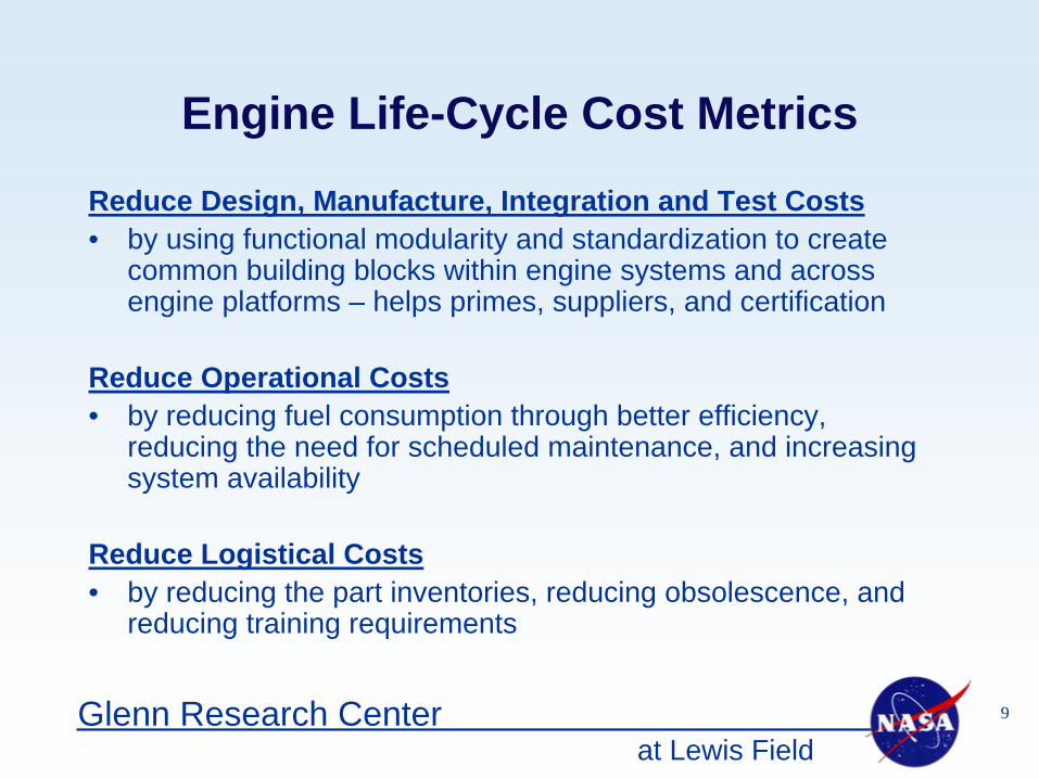
Engine Life-Cycle Cost Metrics
Reduce Design, Manufacture, Integration and Test Costs• by using functional modularity and standardization to create
common building blocks within engine systems and across engine platforms – helps primes, suppliers, and certification
Reduce Operational Costs• by reducing fuel consumption through better efficiency,
reducing the need for scheduled maintenance, and increasing system availability
Reduce Logistical Costs• by reducing the part inventories, reducing obsolescence, and
reducing training requirements
at Lewis Field10Glenn Research Center
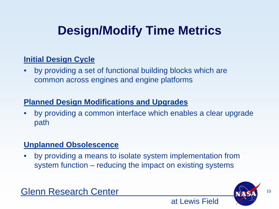
Design/Modify Time Metrics
Initial Design Cycle• by providing a set of functional building blocks which are
common across engines and engine platforms
Planned Design Modifications and Upgrades• by providing a common interface which enables a clear upgrade
path
Unplanned Obsolescence• by providing a means to isolate system implementation from
system function – reducing the impact on existing systems
at Lewis Field11Glenn Research Center
Overview of Distributed Engine Control
• Systems Engineering• Vision• Architecture - Evolutionary or Revolutionary?
at Lewis Field12Glenn Research Center
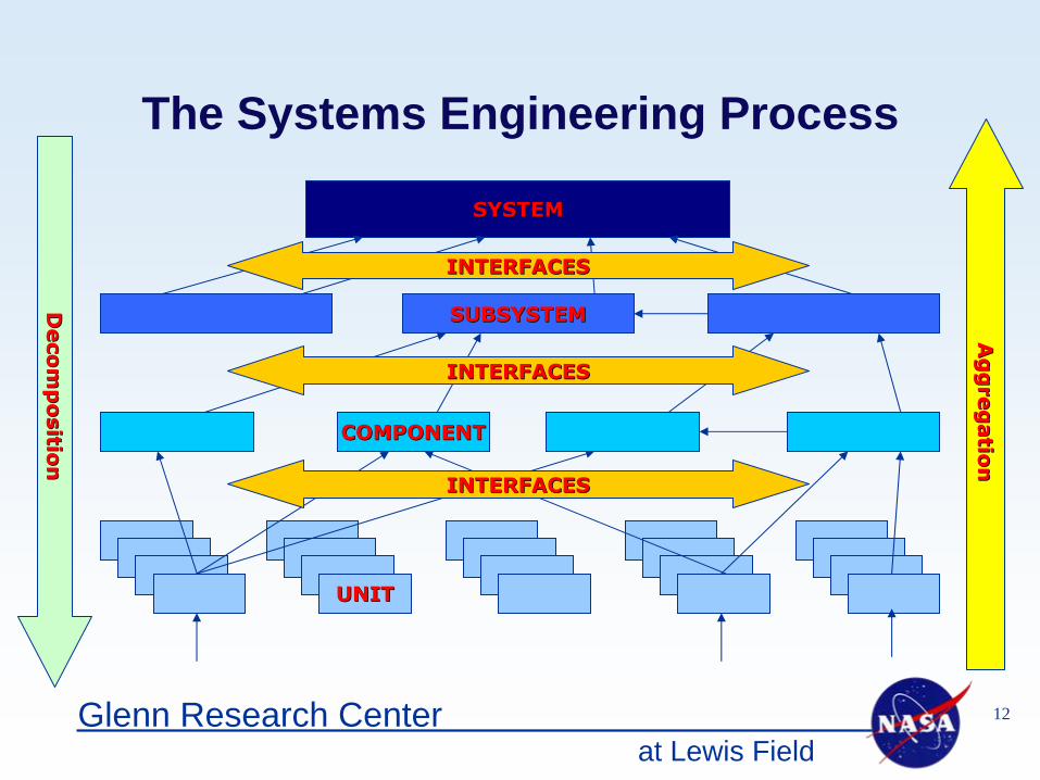
The Systems Engineering Process
SYSTEMSYSTEM
SUBSYSTEMSUBSYSTEM
UNITUNIT
Deco
mp
ositio
nD
eco
mp
ositio
n
Ag
gre
gatio
nA
gg
reg
atio
n
COMPONENTCOMPONENT
INTERFACESINTERFACES
INTERFACESINTERFACES
INTERFACESINTERFACES
at Lewis Field13Glenn Research Center
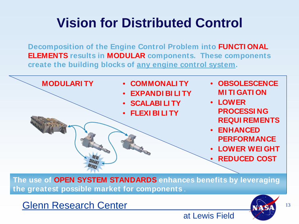
Decomposition of the Engine Control Problem into FUNCTIONAL ELEMENTS results in MODULAR components. These components create the building blocks of any engine control system.
The use of OPEN SYSTEM STANDARDS enhances benefits by leveraging the greatest possible market for components .
• OBSOLESCENCE MITIGATION
• LOWER PROCESSING REQUIREMENTS
• ENHANCED PERFORMANCE
• LOWER WEIGHT• REDUCED COST
• COMMONALITY• EXPANDIBILITY• SCALABILITY• FLEXIBILITY
Vision for Distributed Control
MODULARITY
at Lewis Field14Glenn Research Center
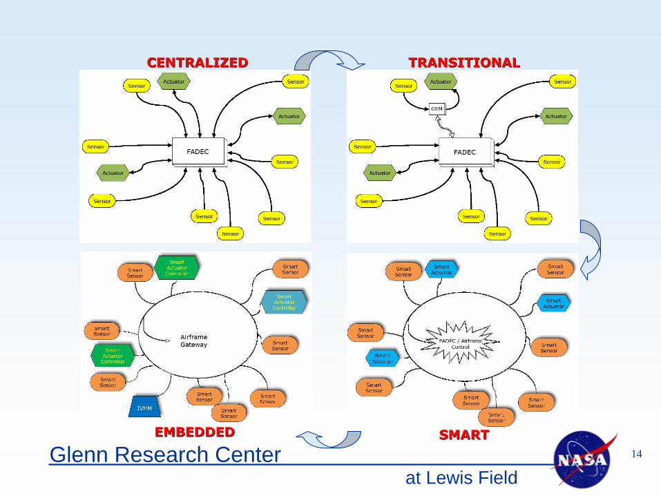
EMBEDDEDEMBEDDED
TRANSITIONALTRANSITIONAL
SMARTSMART
CENTRALIZEDCENTRALIZED
at Lewis Field15Glenn Research Center
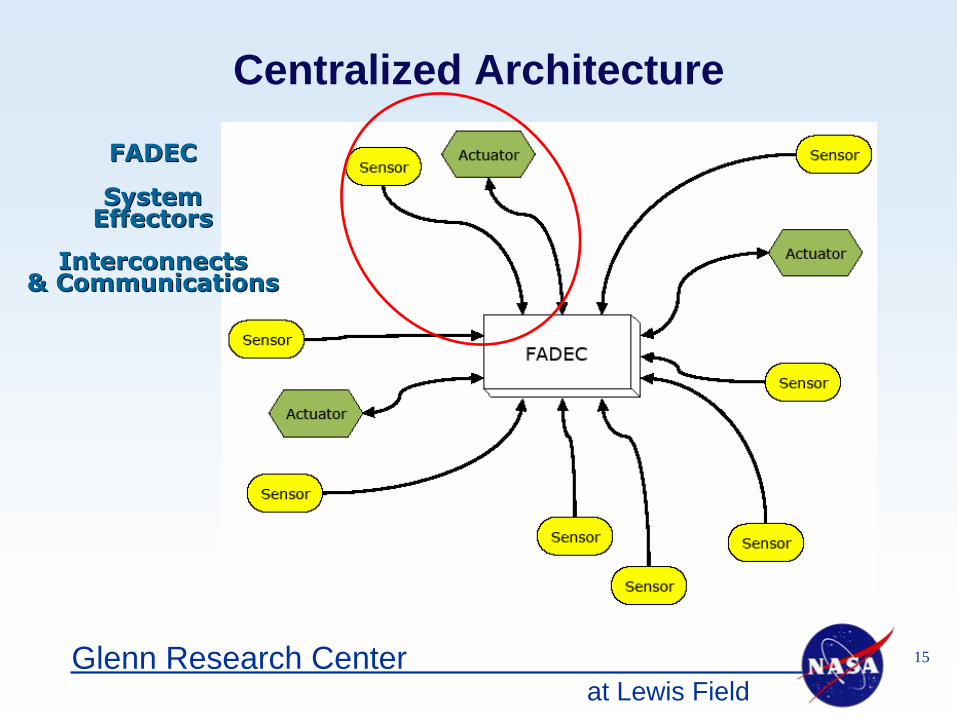
Centralized Architecture
FADECFADEC
System System EffectorsEffectors
InterconnectsInterconnects& Communications& Communications
at Lewis Field16Glenn Research Center
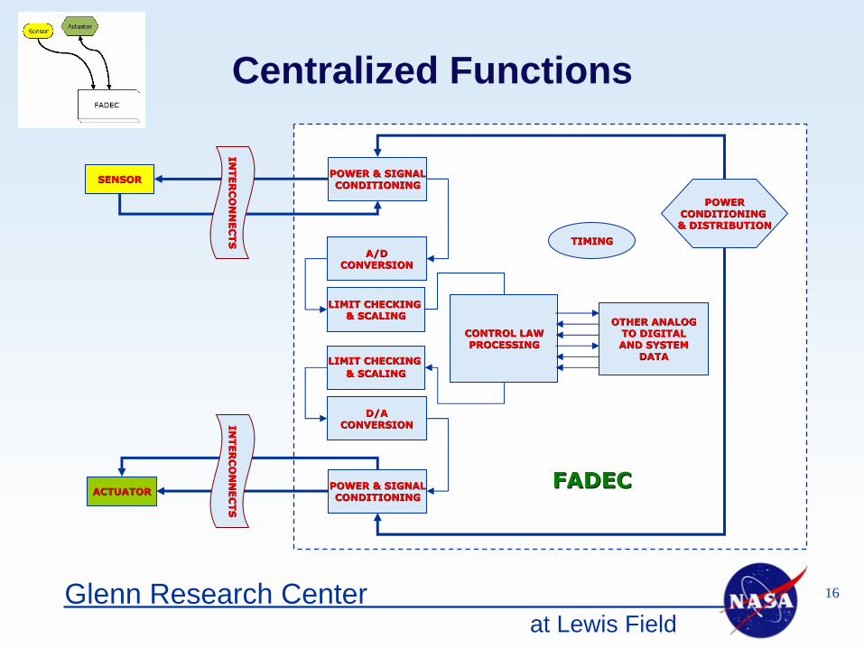
Centralized Functions
SENSORSENSOR POWER & SIGNALPOWER & SIGNALCONDITIONINGCONDITIONING
A/DA/DCONVERSIONCONVERSION
CONTROL LAWCONTROL LAWPROCESSINGPROCESSING
D/AD/ACONVERSIONCONVERSION
ACTUATORACTUATOR POWER & SIGNALPOWER & SIGNALCONDITIONINGCONDITIONING
TIMINGTIMING
FADECFADEC
LIMIT CHECKING LIMIT CHECKING & SCALING& SCALING
LIMIT CHECKING LIMIT CHECKING & SCALING& SCALING
OTHER ANALOGOTHER ANALOGTO DIGITALTO DIGITALAND SYSTEMAND SYSTEM
DATADATA
INTE
RC
ON
NE
CTS
INTE
RC
ON
NE
CTS
INTE
RC
ON
NE
CTS
INTE
RC
ON
NE
CTS
POWERPOWERCONDITIONING CONDITIONING & DISTRIBUTION& DISTRIBUTION
at Lewis Field17Glenn Research Center
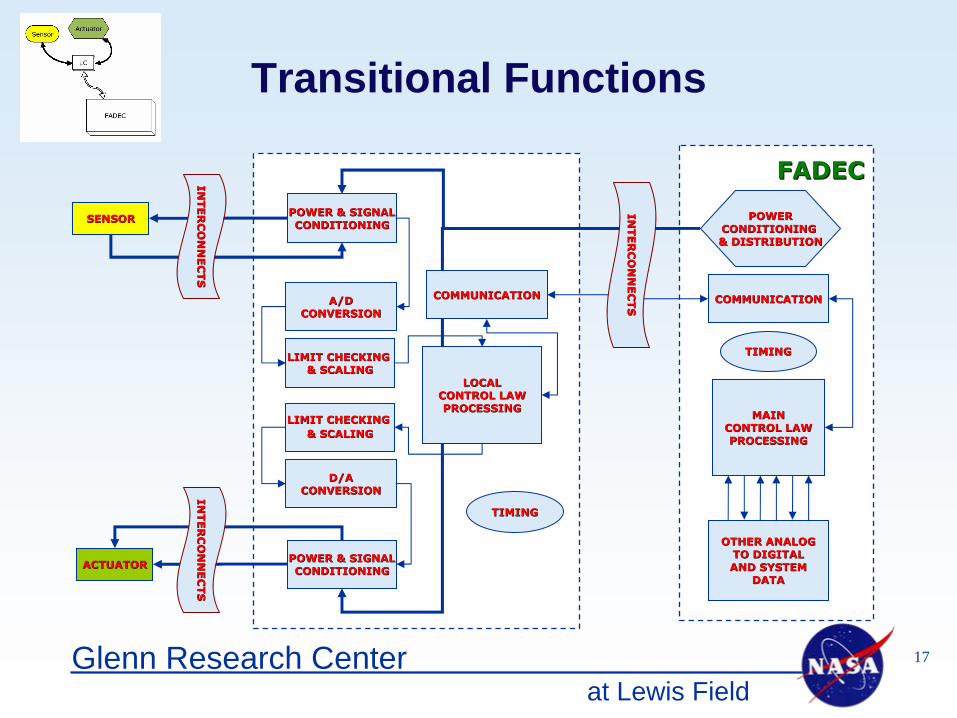
Transitional Functions
SENSORSENSOR
MAINMAINCONTROL LAWCONTROL LAWPROCESSINGPROCESSING
ACTUATORACTUATOR
TIMINGTIMING
INTE
RC
ON
NE
CTS
INTE
RC
ON
NE
CTS
INTE
RC
ON
NE
CTS
INTE
RC
ON
NE
CTS
FADECFADEC
COMMUNICATIONCOMMUNICATION
POWERPOWERCONDITIONING CONDITIONING & DISTRIBUTION& DISTRIBUTION
INTE
RC
ON
NE
CTS
INTE
RC
ON
NE
CTS
OTHER ANALOGOTHER ANALOGTO DIGITALTO DIGITALAND SYSTEMAND SYSTEM
DATADATA
POWER & SIGNALPOWER & SIGNALCONDITIONINGCONDITIONING
A/DA/DCONVERSIONCONVERSION
LOCALLOCALCONTROL LAWCONTROL LAWPROCESSINGPROCESSING
D/AD/ACONVERSIONCONVERSION
POWER & SIGNALPOWER & SIGNALCONDITIONINGCONDITIONING
LIMIT CHECKING LIMIT CHECKING & SCALING& SCALING
LIMIT CHECKING LIMIT CHECKING & SCALING& SCALING
COMMUNICATIONCOMMUNICATION
TIMINGTIMING

at Lewis Field18Glenn Research Center
SENSORSENSORSENSORSENSOR
SPECIFICSPECIFICELECTRONICSELECTRONICS
SUPERVISORYSUPERVISORYCONTROL LAWCONTROL LAWPROCESSINGPROCESSING
TIMINGTIMING
COMMONCOMMONCOMMUNICATIONCOMMUNICATION
MODULEMODULE
STANDARDSTANDARDPOWERPOWER
CONDITIONINGCONDITIONING
Smart Smart SensorSensor
SYSTEMSYSTEMDATADATA
Smart Functions
COMMON COMMON COMMUNICATIONCOMMUNICATION
MODULEMODULE
ACTUATORACTUATORSPECIFICSPECIFIC
ELECTRONICSELECTRONICSACTUATORACTUATOR
Smart Smart ActuatorActuator
LOCALLOCALCONTROL LAWCONTROL LAW
PROCESSORPROCESSOR
COMMON COMMON COMMUNICATIONCOMMUNICATION
MODULEMODULE
INTE
RC
ON
NE
CTS
INTE
RC
ON
NE
CTS
FADECFADEC
at Lewis Field19Glenn Research Center
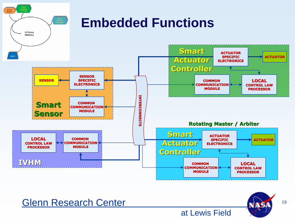
SENSORSENSORSENSORSENSOR
SPECIFICSPECIFICELECTRONICSELECTRONICS
Smart Smart SensorSensor
COMMON COMMON COMMUNICATIONCOMMUNICATION
MODULEMODULE
IVHMIVHM
LOCALLOCALCONTROL LAWCONTROL LAW
PROCESSORPROCESSOR
COMMON COMMON COMMUNICATIONCOMMUNICATION
MODULEMODULE
Embedded Functions
ACTUATORACTUATORSPECIFICSPECIFIC
ELECTRONICSELECTRONICSACTUATORACTUATOR
Smart Smart ActuatorActuator
ControllerControllerLOCALLOCAL
CONTROL LAWCONTROL LAWPROCESSORPROCESSOR
COMMON COMMON COMMUNICATIONCOMMUNICATION
MODULEMODULE
ACTUATORACTUATORSPECIFICSPECIFIC
ELECTRONICSELECTRONICSACTUATORACTUATOR
Smart Smart ActuatorActuator
ControllerControllerLOCALLOCAL
CONTROL LAWCONTROL LAWPROCESSORPROCESSOR
COMMON COMMON COMMUNICATIONCOMMUNICATION
MODULEMODULE
Rotating Master / ArbiterRotating Master / Arbiter
INTE
RC
ON
NE
CTS
INTE
RC
ON
NE
CTS
at Lewis Field20Glenn Research Center
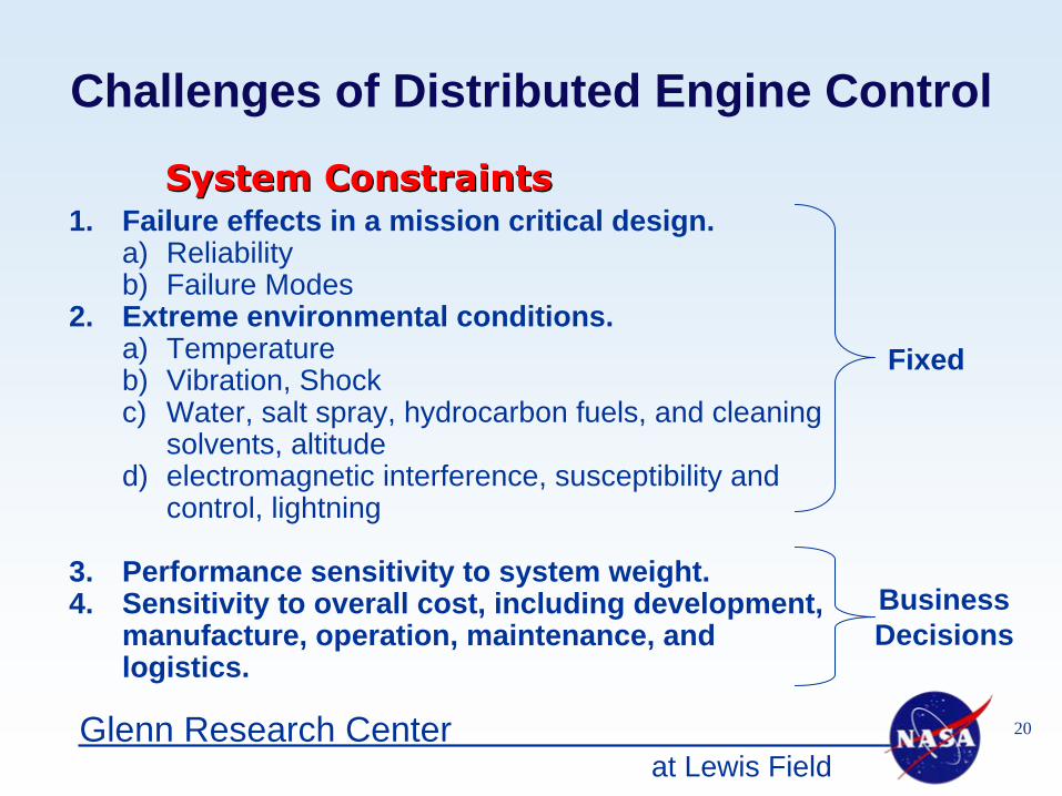
Challenges of Distributed Engine Control
1. Failure effects in a mission critical design.a) Reliabilityb) Failure Modes
2. Extreme environmental conditions.a) Temperatureb) Vibration, Shockc) Water, salt spray, hydrocarbon fuels, and cleaning
solvents, altituded) electromagnetic interference, susceptibility and
control, lightning
3. Performance sensitivity to system weight.4. Sensitivity to overall cost, including development,
manufacture, operation, maintenance, and logistics.
Fixed
Business Decisions
System ConstraintsSystem Constraints
at Lewis Field21Glenn Research Center
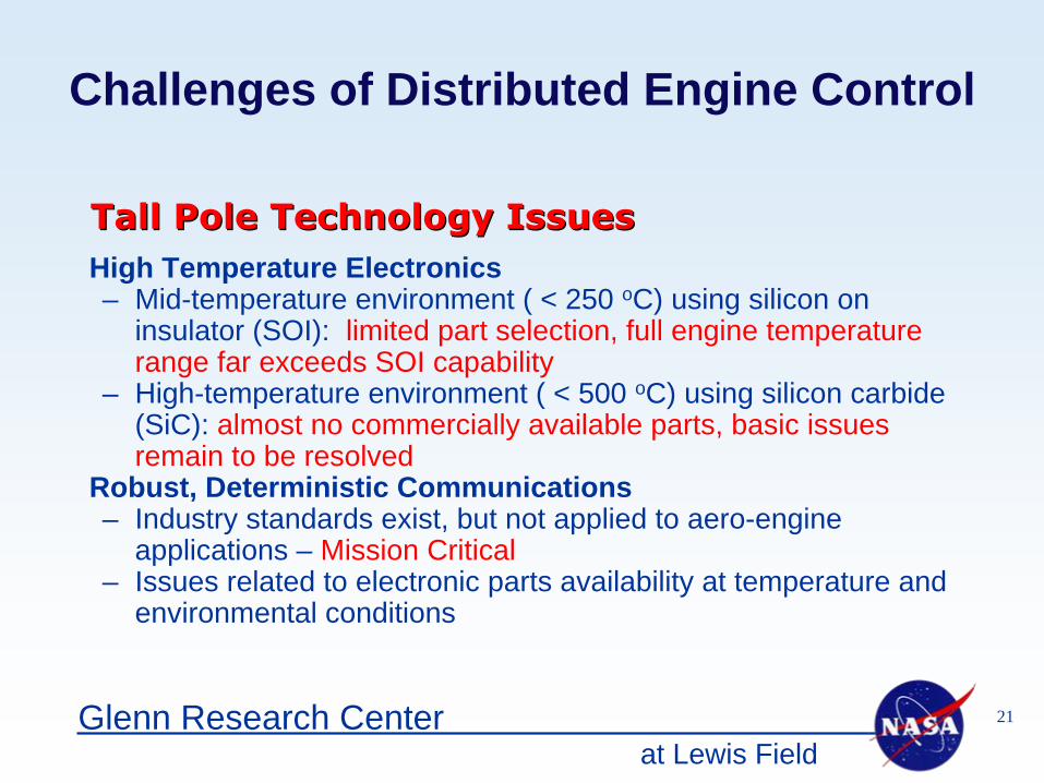
Tall Pole Technology IssuesTall Pole Technology IssuesHigh Temperature Electronics– Mid-temperature environment ( < 250 oC) using silicon on
insulator (SOI): limited part selection, full engine temperature range far exceeds SOI capability
– High-temperature environment ( < 500 oC) using silicon carbide (SiC): almost no commercially available parts, basic issues remain to be resolved
Robust, Deterministic Communications– Industry standards exist, but not applied to aero-engine
applications – Mission Critical– Issues related to electronic parts availability at temperature and
environmental conditions
Challenges of Distributed Engine Control
at Lewis Field22Glenn Research Center
Distributed Engine Control Task Plans
• Distributed Engine Control Working Group (DECWG)• Distributed Engine Control Architecture• Distributed Engine Control Subsystems• High Temperature Electronics and Sensors
at Lewis Field23Glenn Research Center
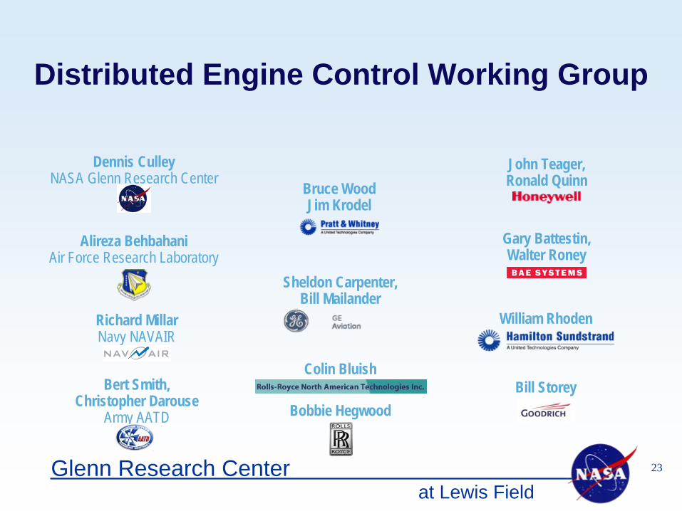
Distributed Engine Control Working Group
Alireza BehbahaniAir Force Research Laboratory
Dennis CulleyNASA Glenn Research Center
Bert Smith,Christopher Darouse
Army AATD
Richard MillarNavy NAVAIR
Bruce WoodJim Krodel
Sheldon Carpenter,Bill Mailander
John Teager,Ronald Quinn
Colin Bluish
Bobbie Hegwood
Gary Battestin,Walter Roney
William Rhoden
Bill Storey
at Lewis Field24Glenn Research Center
Distributed Engine Control Working Group
The main goals of the DECWG• Identify, quantify and validate benefits from the stakeholder
perspective.• Identify the impact of new control strategies on all facets of the
user community; including design, fabrication, assembly, supply chain, and operations.
• Identify regulatory and business barriers which impede the implementation of alternate control philosophies.
• Identify existing and emerging technologies which can be leveraged in the aero-engine control system.
• Identify technology barriers which prevent the implementation of alternate control philosophies and provide guidance to industry for their removal.
• Develop an overall roadmap with which to guide the successful implementation of alternate control philosophies.
at Lewis Field25Glenn Research Center
Distributed Control Architecture
Task Focus• Analyze the potential benefits, especially for volume and
weight reduction, due to system architecture and design• Investigate the availability and application of open
standards for engine control• Explore the use and availability of commercial and military
off-the-shelf (COTS / MOTS) hardware• Identify emerging embedded hardware architectures and
technologies that can be applied to aeropropulsion engine control
at Lewis Field26Glenn Research Center
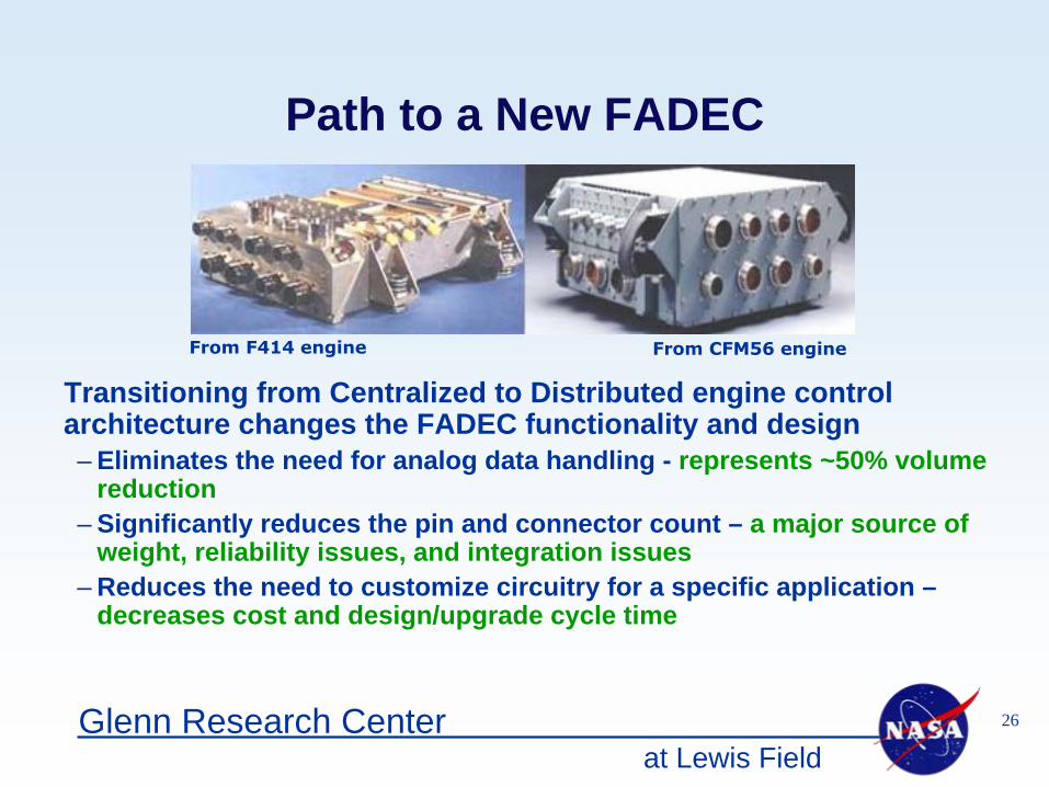
Path to a New FADEC
From F414 engine From CFM56 engine
Transitioning from Centralized to Distributed engine control architecture changes the FADEC functionality and design– Eliminates the need for analog data handling - represents ~50% volume
reduction– Significantly reduces the pin and connector count – a major source of
weight, reliability issues, and integration issues– Reduces the need to customize circuitry for a specific application –
decreases cost and design/upgrade cycle time
at Lewis Field27Glenn Research Center
New Technologies for Harsh Environment Computing
High performance computer hardware, in a small form factor, based on robust open standards, is being rapidly pursued by industry. At least two of these competing commercial platform specifications have potential for aeropropulsion control systems.
– A small form factor is critical to address the shock and vibration environment on engine and airframe applications with minimal support structure, i.e., weight and volume
– Conduction cooled hardware is critical to address the high power density of small form factor modules and the lack of convection cooling in engine-mounted applications
at Lewis Field28Glenn Research Center
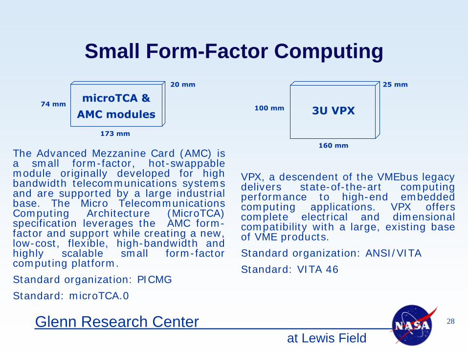
Small Form-Factor Computing
microTCA
&
AMC modules74 mm
173 mm
20 mm
100 mm
160 mm
25 mm
3U VPX
The Advanced Mezzanine Card (AMC) is a small form-factor, hot-swappable module originally developed for high bandwidth telecommunications systems and are supported by a large industrial base. The Micro Telecommunications Computing Architecture (MicroTCA) specification leverages the AMC form- factor and support while creating a new, low-cost, flexible, high-bandwidth and highly scalable small form-factor computing platform.
Standard organization: PICMG
Standard: microTCA.0
VPX, a descendent of the VMEbus legacy delivers state-of-the-art computing performance to high-end embedded computing applications. VPX offers complete electrical and dimensional compatibility with a large, existing base of VME products.
Standard organization: ANSI/VITA
Standard: VITA 46
at Lewis Field29Glenn Research Center
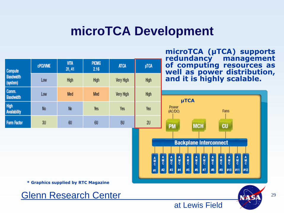
microTCA Development
* Graphics supplied by RTC Magazine
microTCA
(μTCA) supports redundancy management of computing resources as well as power distribution, and it is highly scalable.
μTCA
at Lewis Field30Glenn Research Center
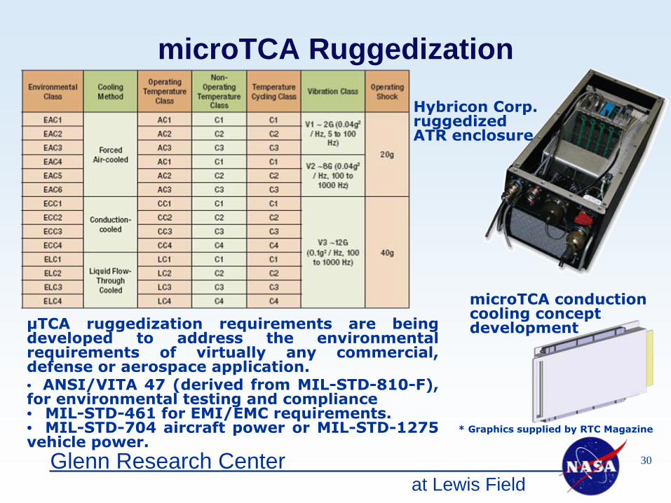
microTCA Ruggedization
Hybricon
Corp. ruggedized
ATR enclosure
microTCA
conduction cooling concept development
* Graphics supplied by RTC Magazine
μTCA ruggedization
requirements are being developed to address the environmental requirements of virtually any commercial, defense or aerospace application.• ANSI/VITA 47 (derived from MIL-STD-810-F), for environmental testing and compliance• MIL-STD-461 for EMI/EMC requirements.• MIL-STD-704 aircraft power or MIL-STD-1275 vehicle power.
at Lewis Field31Glenn Research Center
Distributed Engine Control Subsystems
Task Focus • Investigate the availability and application of open
standards for embedded components in distributed systems
• Investigate the performance of commercially available electronic components under extreme environmental conditions
• Analyze the environmental requirements for embedded engine effectors
• Identify potential strategies for harsh environment control• Drive applications into the high temperature electronics
development effort
at Lewis Field32Glenn Research Center
Smart Control Effectors
What is a “smart” sensor or a “smart” actuator?
Smart transducer: A smart transducer is a transducer that provides functions beyond those necessary for generating a correct representation of a sensed or controlled quantity. This functionality typically simplifies the integration of the transducer into applications in a networked environment. (adapted from IEEE 1451 working group)
Most people have their own concept of what “smart” means but the issue is being addressed.

at Lewis Field33Glenn Research Center
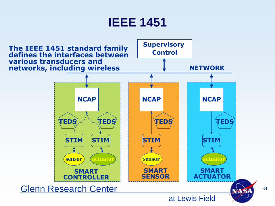
IEEE 1451Standard for a Smart Transducer Interface for Sensors and Actuators
The objective of IEEE 1451 is to develop a smart transducer interface standard to make it easier for transducer manufacturers to develop smart devices and to interface those devices to networks, systems, and instruments by incorporating existing and emerging sensor and networking technologies. The standard interface consists of three parts.
– Smart Transducer Interface Module (STIM) – electronics to convert the native transducer signal to digital quantities.
– Transducer Electronic Data Sheet (TEDS) – a memory which contains transducer specific information such as; identification, calibration, correction data, measurement range, manufacture-related information, etc
– Network-capable application processor (NCAP) - the hardware and software that provides the communication function between the STIM and the network
at Lewis Field34Glenn Research Center
The IEEE 1451 standard family defines the interfaces between various transducers and networks, including wireless
IEEE 1451
actuator
NCAP
sensor
NCAP NCAP
actuatorsensor
Supervisory Control
NETWORK
TEDS TEDS TEDS TEDS
STIM STIM STIM STIM
SMART CONTROLLER
SMARTSENSOR
SMART ACTUATOR
at Lewis Field35Glenn Research Center
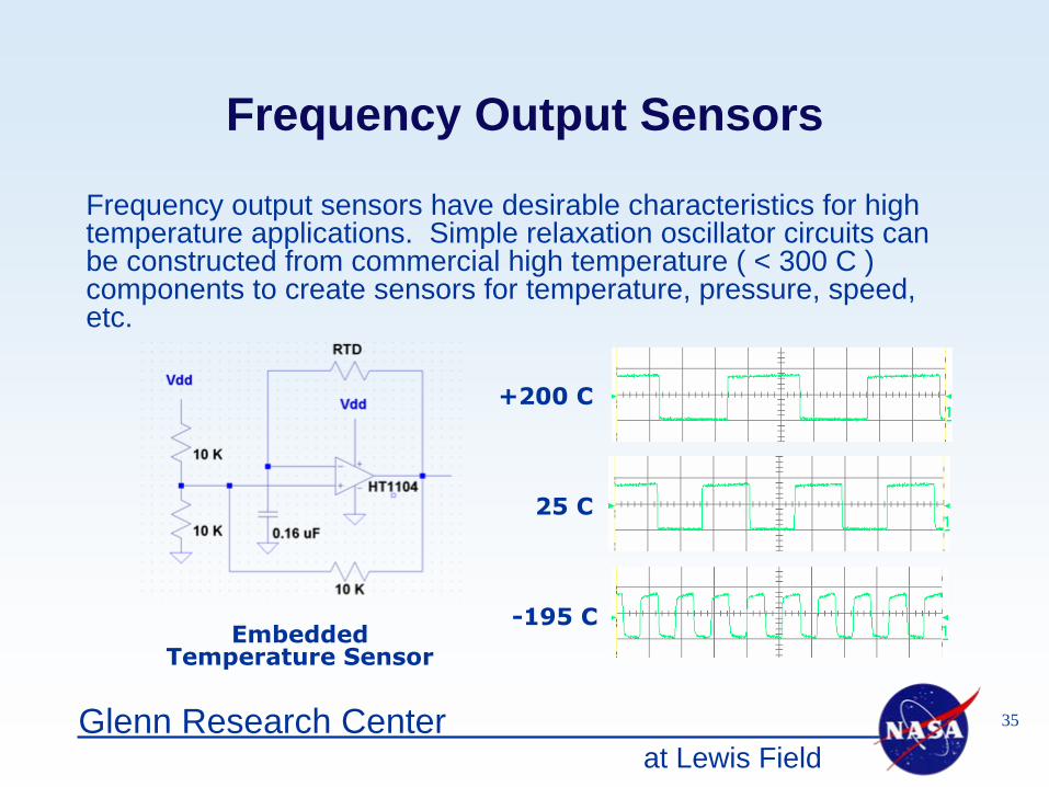
Frequency Output Sensors
Embedded Temperature Sensor
Frequency output sensors have desirable characteristics for high temperature applications. Simple relaxation oscillator circuits can be constructed from commercial high temperature ( < 300 C ) components to create sensors for temperature, pressure, speed, etc.
-195 C
25 C
+200 C
at Lewis Field36Glenn Research Center
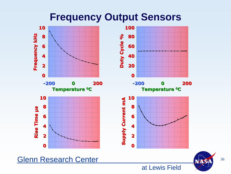
Frequency Output Sensors
Temperature Temperature 00CC--200200 00 200200
Temperature Temperature 00CC--200200 00 200200
Fre
qu
en
cy k
Hz
Fre
qu
en
cy k
Hz
Ris
e T
ime
Ris
e T
ime μμ
ss
Su
pp
ly C
urr
en
t S
up
ply
Cu
rren
t m
Am
AD
uty
Cycl
e %
Du
ty C
ycl
e %
00
22
44
66
88
1010
00
2020
4040
6060
8080
100100
00
22
44
66
88
1010
00
22
44
66
88
1010
at Lewis Field37Glenn Research Center
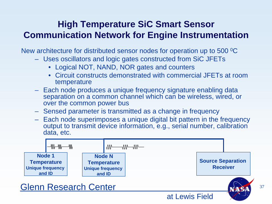
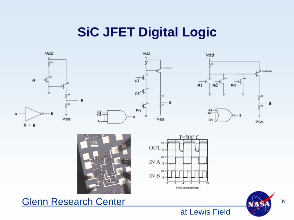
High Temperature SiC Smart Sensor Communication Network for Engine Instrumentation
New architecture for distributed sensor nodes for operation up to 500 0C– Uses oscillators and logic gates constructed from SiC JFETs
• Logical NOT, NAND, NOR gates and counters• Circuit constructs demonstrated with commercial JFETs at room
temperature– Each node produces a unique frequency signature enabling data
separation on a common channel which can be wireless, wired, or over the common power bus
– Sensed parameter is transmitted as a change in frequency– Each node superimposes a unique digital bit pattern in the frequency
output to transmit device information, e.g., serial number, calibration data, etc.
Node 1Temperature
Unique frequency and ID
Node NTemperature
Unique frequency and ID
Source Separation Receiver
at Lewis Field38Glenn Research Center
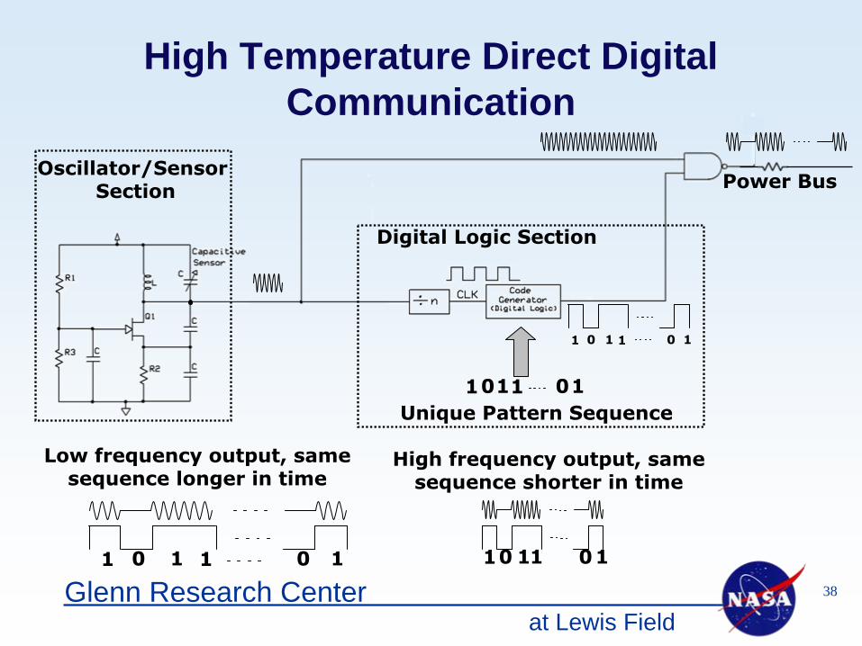
High Temperature Direct Digital Communication
01 11 10
Oscillator/Sensor Section
01 11 10Unique Pattern Sequence
Digital Logic Section
01 1 1 10
01 1 1 10
Low frequency output, same sequence longer in time
High frequency output, same sequence shorter in time
Power Bus
at Lewis Field39Glenn Research Center
SiC JFET Digital Logic
at Lewis Field40Glenn Research Center
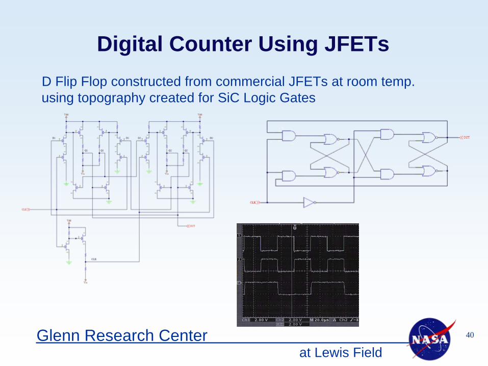
Digital Counter Using JFETsD Flip Flop constructed from commercial JFETs at room temp. using topography created for SiC Logic Gates
at Lewis Field41Glenn Research Center
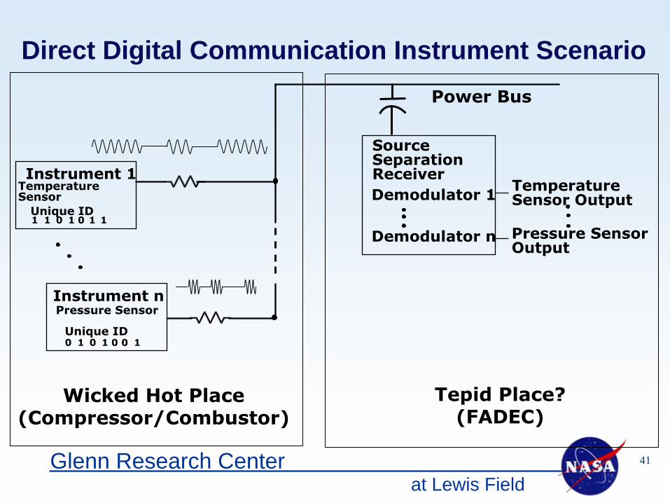
Direct Digital Communication Instrument Scenario
Source Separation ReceiverDemodulator 1
Demodulator n1 1 0 1 0 1 1
Instrument 1
Unique ID
Temperature Sensor
0 1 0 1 0 0 1
Instrument n
Unique ID
Pressure Sensor
Temperature Sensor Output
Pressure SensorOutput
Wicked Hot Place (Compressor/Combustor)
Tepid Place?(FADEC)
Power Bus
at Lewis Field42Glenn Research Center
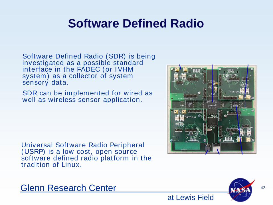
Software Defined Radio
Software Defined Radio (SDR) is being investigated as a possible standard interface in the FADEC (or IVHM system) as a collector of system sensory data.
SDR can be implemented for wired as well as wireless sensor application.
Universal Software Radio Peripheral (USRP) is a low cost, open source software defined radio platform in the tradition of Linux.
at Lewis Field43Glenn Research Center
High Temperature Electronics & Sensors
Task Focus • Develop the technologies to implement reliable, integrated
electronics for high temperature applications– Stable, high temperature transistors– Multilevel interconnect structures for complex
integrated circuit development– High performance packaging and interconnects for
reliable, extreme environment applications• Focus component development on applications developed
within the DEC project• Develop high temperature sensing capabilities
at Lewis Field44Glenn Research Center
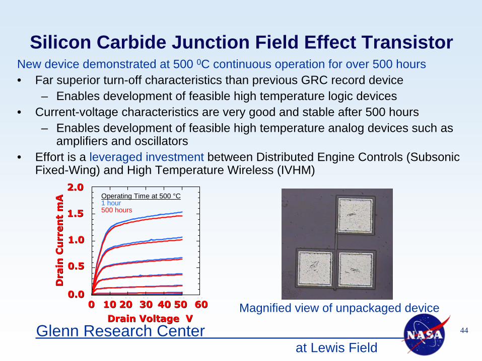
Silicon Carbide Junction Field Effect Transistor
Magnified view of unpackaged device
New device demonstrated at 500 0C continuous operation for over 500 hours• Far superior turn-off characteristics than previous GRC record device
– Enables development of feasible high temperature logic devices • Current-voltage characteristics are very good and stable after 500 hours
– Enables development of feasible high temperature analog devices such as amplifiers and oscillators
• Effort is a leveraged investment between Distributed Engine Controls (Subsonic Fixed-Wing) and High Temperature Wireless (IVHM)
Drain Voltage VDrain Voltage V
0 10 20 30 40 50 60
Operating Time at 500 °C1 hour500 hours
Dra
in C
urr
en
t D
rain
Cu
rren
t m
Am
A
0.00.0
0.50.5
1.01.0
1.51.5
2.02.0
60605050404030302020101000

at Lewis Field45Glenn Research Center
NASA builds a hot temperature circuit chip
CLEVELAND, Sept. 11 (UPI) -- U.S. space agency scientists have designed and built a circuit chip that can operate for long periods in high temperature environments.In the past, integrated circuit chips could not withstand more than a few hours of high temperatures before degrading or failing. The National Aeronautics and Space Administration's new chip exceeded 1,700 hours of continuous operation at 500 degrees Celsius (932 degrees Fahrenheit) -- a 100-fold increase over previous chips.NASA said the new silicon carbide differential amplifier integrated circuit chip might provide benefits to anything requiring long-lasting electronic circuits in very hot environments, such as small circuitry in hot areas of jet engines as well as automotive engines."It's really a significant step toward mission-enabling harsh environment electronics," said Phil Neudeck, an electronics engineer at NASA's Glenn Research Center in Cleveland. "This new capability can eliminate the additional plumbing, wires, weight and other performance penalties required to liquid-cool traditional sensors and electronics near the hot combustion chamber, or the need to remotely locate them elsewhere where they aren't as effective."Copyright 2007 by United Press International. All Rights Reserved.
at Lewis Field46Glenn Research Center
health parameters
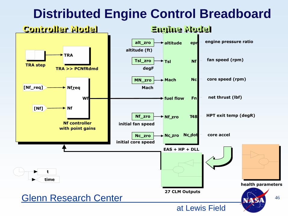
Distributed Engine Control Breadboard
t
time
Controller ModelController ModelController ModelController Model
TRA stepTRA >> PCNfRdmd
Nf
controllerwith point gains
[Nf]
TRA
[Nf_req] Nf_req
Nf
Wf
Engine ModelEngine ModelEngine ModelEngine Model
27 CLM Outputs
net thrust (lbf)
initial fan speed
initial core speed
fan speed (rpm)
engine pressure ratio
degF
core speed (rpm)
core accel
altitude (ft)
Mach
HPT exit temp (degR)
EAS + HP + DLL
altitude
Tsl
Mach
fuel flow
Nf_zro
Nc_zro
epr
Nf
Nc
Fn
T48
Nc_dot
alt_zro
Tsl_zro
MN_zro
Nf_zro
Nc_zro
at Lewis Field47Glenn Research Center
Opportunities for Collaboration
No funded opportunities under SFW
• Integrated distributed system tools– Software partitioning and development– System modeling and performance analysis – System reliability modeling
• Engine environment requirements definition• Sensor / actuator development and packaging• Standards development - all types• Failure modes and effects of distributed systems• Flight certification requirements for distributed systems
at Lewis Field48Glenn Research Center
References
Status, Vision, and Challenges of an Intelligent Distributed Engine Control Architecture, A. Behbahani, D. Culley, et al, SAE2007-01-3859, SAE 2007 Aerotech Congress and Exhibit, Los Angeles, CA, September 17-20, 2007
Concepts for Distributed Engine Control, D. Culley, R. Thomas, J. Saus, AIAA-2007-5709, 43rd AIAA/ASME/SAE/ASEE Joint Propulsion Conference and Exhibit, Cincinnati, Ohio, July 8-11, 2007


