
Draft Erosion & Sediment Control Plan
Rotoma/Rotoiti Wastewater Treatment Plant and Land Disposal System Rotorua Lakes Council
Draft Erosion & Sediment Control Plan
Rotoma/Rotoiti Wastewater
Treatment Plant and Land
Disposal System
Rotorua Lakes Council
© Opus International Consultants Ltd 2016
Prepared By Opus International Consultants Ltd
Joshua Fraser Rotorua Office
Civil Design Technician 1st Floor, 1071 Hinemoa Street
PO Box 1245, Rotorua 3040
New Zealand
Reviewed By Telephone: +64 7 343 1400
Nina Reddy Facsimile: +64 7 343 1401
Senior Project Manager
Date: 04/05/2016
Reference: 2-89993.00
Status: Draft
Approved for
Release By
Fred Shilton
Team Leader

i
2-89993.00 | 04/05/2016 Opus International Consultants Ltd
Contents
1 Project Overview ................................................................................................ 1
1.1 Location ............................................................................................................................. 1 1.2 Background ....................................................................................................................... 2 1.3 Site Description ................................................................................................................. 2 1.4 Proposal ............................................................................................................................ 2
2 Erosion Controls ................................................................................................ 4 2.1 Vegetation Clearance ........................................................................................................ 4
2.2 Offsite Runoff (Clean Water) onto the Work Site ............................................................. 4 2.3 Control of Onsite Runoff (Dirty Water) ............................................................................ 4 2.4 Earthworks Stabilisation ................................................................................................... 4
2.5 Stockpile Areas .................................................................................................................. 4
3 Sediment Controls.............................................................................................. 5 3.1 Super Silt Fences ............................................................................................................... 5 3.2 Rock Check Dams.............................................................................................................. 6
3.3 Clean Water Cutout Diversion Channel ............................................................................ 6 3.4 Stabilised Entranceway ..................................................................................................... 7 3.5 Sediment Retention Pond ................................................................................................. 8
4 Dust Control ....................................................................................................... 9 4.1 Method/Procedure ............................................................................................................ 9 4.2 Details of Dust Control ...................................................................................................... 9
5 Implementing the Plan (Methodology) .............................................................. 11
Appendix A: Sediment and Erosion Control Plan Drawing ........................................ 12

1
2-89993.00 | 04/05/2016 Opus International Consultants Ltd
1 Project Overview
This Erosion and Sediment Control Plan (ESCP) outlines measures to minimise the discharge of
sediment offsite during construction of the Rotoma/Rotoiti Waste Water Treatment Plant (WWTP)
and Land Disposal System (LDS), including construction of the access road.
The ESCP is based on the Concept Design provided by Pattle Delamore Partners Ltd (PDP). A
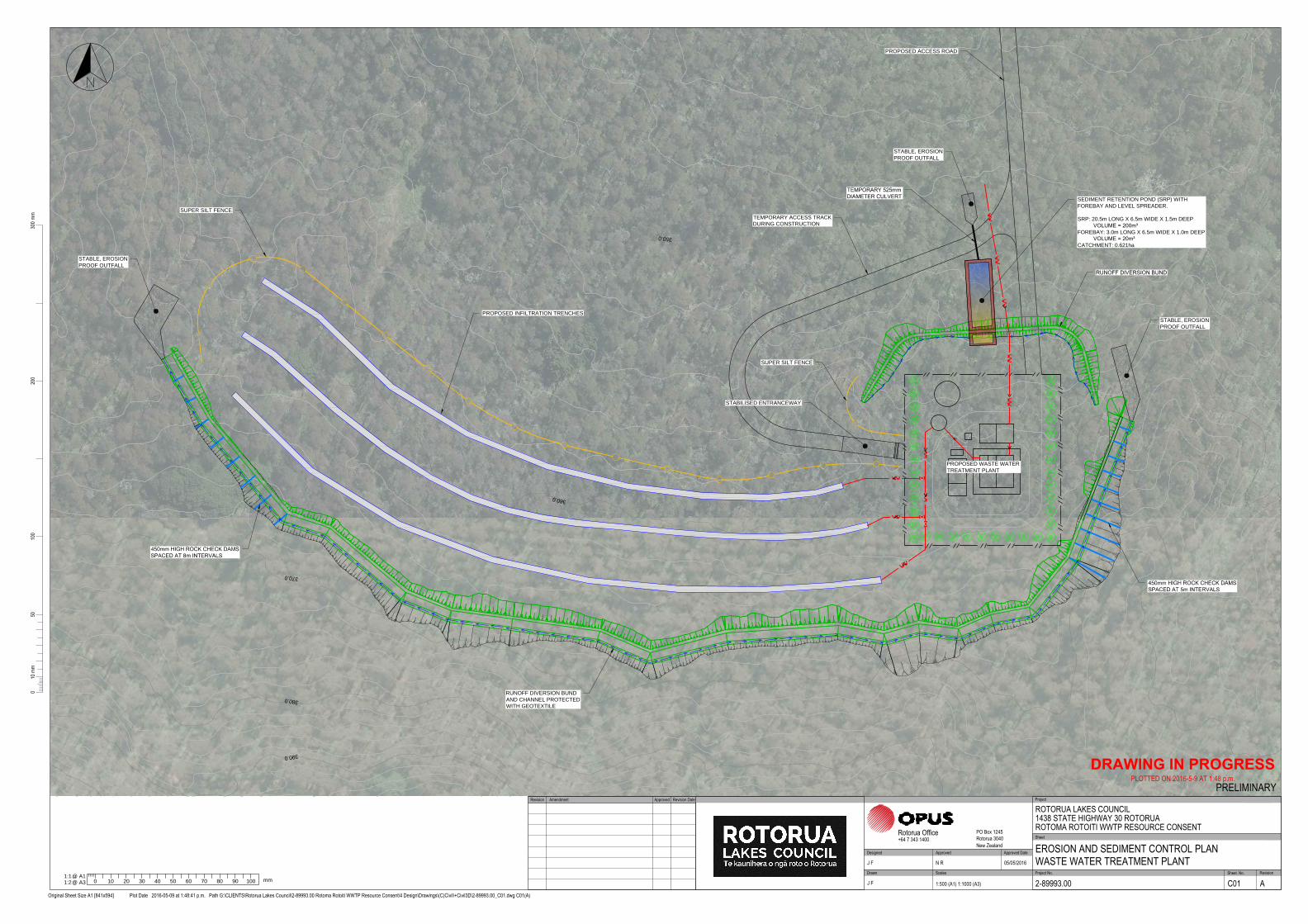
drawing of the proposed erosion and sediment control measures is included in Appendix A.
This ESCP has been prepared for the Contractor to use as a guideline for addressing erosion and
sediment control issues during construction, and to provide an indication to Bay of Plenty Regional
Council of likely effects and proposed mitigation measures.
The location and extent of controls may however change due to:
The documented control is no longer practical.
There is a further need to install additional controls.
The location of the planned control is not practical.
The contractors construction methodology varies from the staging of works described in this
document.
Inclement weather demands additional controls irrespective of the above.
At all times the Contractor must comply with best practice.
A final ESCP is expected to be required as a condition of consent, to be prepared by the Contractor
and submitted prior to the commencement of works.
1.1 Location
The proposed WWTP will be located to the east of the city of Rotorua about 27km from the CBD as
shown in Figure 1 below.
Figure 1: Location Diagram (Source: LINZ Data Service)
WWTP &
LDS Location

2
2-89993.00 | 04/05/2016 Opus International Consultants Ltd
The project is located within the Rotorua District boundary, and within the Bay of Plenty Regional
boundary.
1.2 Background
Water quality in the Rotorua lakes has been deteriorating over a number of years. The degradation
of water quality is a result of nutrient and bacterial inputs from the surrounding catchments.
Nitrogen and pathogens from farming and septic tanks, and phosphorus from soil erosion and
detergents, have contributed to increased public health risk for bathing, drinking water and has led
to the proliferation of blue-green algae.
1.3 Site Description
The proposed WWTP and LDS is located on an elevated plateau south of State Highway 30 (SH30),
which runs along the southern shore of Lake Rotoiti, as shown on Figure 1. The site for the WWTP
is approximately 5.5ha, with a 700m access road from SH30.
The site is on a dissected plateau on the surface of a rhyolite dome complex, with the steeper slopes
of a younger part of the rhyolite dome complex rising up to the south of the plateau surface. The
site is underlain by rhyolite pyroclastics and lavas of the Te Rere Formation, which forms a part of
the Haroharo Subgroup derived from the Okataina Volcanic Centre1. The nearest fault exclusion
zones are approximately 2km south and 3.5km east of the site.
Extensive ground investigations were undertaken to inform development of the proposal. These
investigations were undertaken in two stages, and produced the following reports:
Lake Rotoiti Wastewater Scheme - Stage 1 Geotechnical Investigation (Opus, 2015)
Rotoiti - Rotoma WWTP and Land Disposal System: Stage 2 Hydrogeological Investigation
(PDP, 2016)
The investigations included hand auger scala penetrometer tests, drilling of investigation
boreholes, groundwater monitoring piezometers, excavation of test pits, soil samples, and
infiltration tests. Geology encountered during the investigations comprised predominantly loose,
poorly sorted rhyolitic sands and gravels with occasional rhyolite and obsidian cobbles and
boulders. Near the surface (typically between 1-3m below ground level), a layer of lower
permeability silty material was encountered in some of the boreholes.
The Stage 2 Hydrogeological Investigation (PDP, 2016) found that the depth of the permanent
water table encountered during drilling resided at approximately the same relative level as the
water level in Lake Rotoiti (approximately 280m RL). The soil profile was found to be of very high
permeability and free draining.
1.4 Proposal
Rotorua Lakes Council propose to construct, operate, and maintain a WWTP and LDS as part of
the Rotoma/Rotoiti Sewerage Scheme. When complete, the Scheme will provide sewerage
reticulation to every property within the East Rotoiti area and Rotoma area for treatment and
1 Geology of the Rotorua Area (Leonard et al. 2010)
3
2-89993.00 | 04/05/2016 Opus International Consultants Ltd
disposal at the Rotoma/Rotoiti WWTP and LDS. The scheme will replace the existing individual
septic tank and on-site treatment systems servicing properties within the two communities.
Pattle Delamore Partners (PDP) have developed a concept design for the WWTP and LDS, utilising
chemical assisted membrane bioreactor (MBR) technology prior to disposal to rapid infiltration
trenches. The concept design identifies target effluent quality standards, and includes provisions
to minimise odour and noise, and to reduce the visual impact at the site.
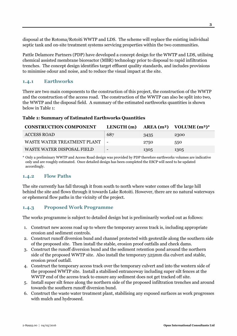
1.4.1 Earthworks
There are two main components to the construction of this project, the construction of the WWTP
and the construction of the access road. The construction of the WWTP can also be split into two,
the WWTP and the disposal field. A summary of the estimated earthworks quantities is shown
below in Table 1:
Table 1: Summary of Estimated Earthworks Quantities
CONSTRUCTION COMPONENT LENGTH (m) AREA (m²) VOLUME (m³)*
ACCESS ROAD 687 3435 2300
WASTE WATER TREATMENT PLANT - 2750 550
WASTE WATER DISPOSAL FIELD - 1305 1305
* Only a preliminary WWTP and Access Road design was provided by PDP therefore earthworks volumes are indicative
only and are roughly estimated. Once detailed design has been completed the ESCP will need to be updated
accordingly.
1.4.2 Flow Paths
The site currently has fall through it from south to north where water comes off the large hill
behind the site and flows through it towards Lake Rotoiti. However, there are no natural waterways
or ephemeral flow paths in the vicinity of the project.
1.4.3 Proposed Work Programme
The works programme is subject to detailed design but is preliminarily worked out as follows:
1. Construct new access road up to where the temporary access track is, including appropriate
erosion and sediment controls.
2. Construct runoff diversion bund and channel protected with geotextile along the southern side
of the proposed site. Then install the stable, erosion proof outfalls and check dams.
3. Construct the runoff diversion bund and the sediment retention pond around the northern
side of the proposed WWTP site. Also install the temporary 525mm dia culvert and stable,
erosion proof outfall.
4. Construct the temporary access track over the temporary culvert and into the western side of
the proposed WWTP site. Install a stabilised entranceway including super silt fences at the
WWTP end of the access track to ensure any sediment does not get tracked off site.
5. Install super silt fence along the northern side of the proposed infiltration trenches and around
towards the southern runoff diversion bund.
6. Construct the waste water treatment plant, stabilising any exposed surfaces as work progresses
with mulch and hydroseed.
4
2-89993.00 | 04/05/2016 Opus International Consultants Ltd
7. Trench the infiltration trenches and construct the disposal field. Stabilise any exposed
surfaces with mulch and hydroseed.
8. Once construction is finished and all exposed surfaces are stabilised, remove all existing
erosion and sediment control measures.
9. Finish constructing the access road up to the final location at the WWTP. Remove the
temporary access track. Ensure appropriate erosion and sediment controls are in place
throughout this work.
10. Ensure all exposed surfaces are stabilised then remove all final erosion and sediment controls.
The surface vegetation is to be removed and disposed of offsite. Erosion and sediment control
measures are to be installed before works commence.
Erosion and sediment control measures for these activities are detailed in the sections to follow.
Earthworks are normally not allowed during the period 1 May to 30 September inclusive during
any year, apart from necessary maintenance works, unless approved in writing by the Bay of Plenty
Regional Council.
2 Erosion Controls
2.1 Vegetation Clearance
Any trees and/or other vegetation will be cleared, as required and disposed of offsite.
2.2 Offsite Runoff (Clean Water) onto the Work Site
During the construction works, the offsite runoff will be diverted away from any earth works for as
long as practically possible and the runoff will continue to flow through existing natural flow paths
where applicable. This will be done via a runoff diversion bund and channel protected with
geotextile, rock check dams and stable, erosion proof outfalls. Refer to Appendix A for bund
locations.
2.3 Control of Onsite Runoff (Dirty Water)
Dirty water will be treated via a combination of super silt fences and a sediment retention pond. The
super silt fences are used to treat the runoff from the construction of the proposed infiltration
trenches and the stabilised entranceway. The sediment retention pond is used to treat the
contaminated runoff from the construction of the WWTP.
2.4 Earthworks Stabilisation
Bare areas subject to erosion will be progressively stabilised as they are completed. Stabilisation
can be achieved through applying periodic hydro seeding, mulching or hay. Embankment, cut
slopes, and any exposed areas should be stabilised as soon as they are at design level.
2.5 Stockpile Areas
Construction methodology and stockpile locations will be finalised by the Contractor closer to the
construction date. Erosion and sediment control requirements of the stockpile areas will be in

5
2-89993.00 | 04/05/2016 Opus International Consultants Ltd
compliance with the Bay of Plenty Regional Councils Erosion and Sediment Control Guidelines for
Land Disturbing Activities. The stockpiles will be stabilised using grass or hydro seeding as
appropriate and contained using either silt fence or, where available, dirty water diversion
channels.
Stockpile zones are to be identified before works start, in discussion between the Contractor and
the land owners.
While not part of this erosion and sediment control plan, it should be noted that all cut to waste
sites will need to be assessed for resource consent requirements prior to dumping.
3 Sediment Controls
A range of controls have been identified for use on the construction site. These controls include
super silt fences, rock check dams, runoff diversion bunds and channels protected with geotextiles,
a stabilised entranceway, stable, erosion proof outfalls and a sediment retention pond. The location
of these control measures are indicated in Appendix A. The detailed design of these controls are
specified below.
3.1 Super Silt Fences
The location of silt fences required on the site is indicated on the attached plan (Appendix A).
Super Silt fences shall be constructed in accordance with the Bay of Plenty Regional Council
guideline document 2010/01 Erosion and Sediment Control Guidelines for Land Disturbing
Activities, and as shown by the general design below:
6
2-89993.00 | 04/05/2016 Opus International Consultants Ltd
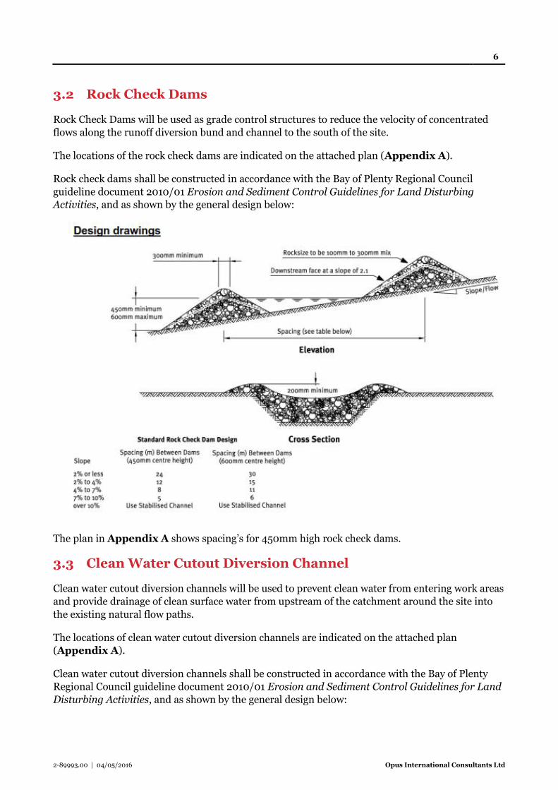
3.2 Rock Check Dams
Rock Check Dams will be used as grade control structures to reduce the velocity of concentrated
flows along the runoff diversion bund and channel to the south of the site.
The locations of the rock check dams are indicated on the attached plan (Appendix A).
Rock check dams shall be constructed in accordance with the Bay of Plenty Regional Council
guideline document 2010/01 Erosion and Sediment Control Guidelines for Land Disturbing
Activities, and as shown by the general design below:
The plan in Appendix A shows spacing’s for 450mm high rock check dams.
3.3 Clean Water Cutout Diversion Channel
Clean water cutout diversion channels will be used to prevent clean water from entering work areas
and provide drainage of clean surface water from upstream of the catchment around the site into
the existing natural flow paths.
The locations of clean water cutout diversion channels are indicated on the attached plan
(Appendix A).
Clean water cutout diversion channels shall be constructed in accordance with the Bay of Plenty
Regional Council guideline document 2010/01 Erosion and Sediment Control Guidelines for Land
Disturbing Activities, and as shown by the general design below:

7
2-89993.00 | 04/05/2016 Opus International Consultants Ltd
3.4 Stabilised Entranceway
The stabilised entranceway will be used to prevent the site access point from becoming a sediment
source and to prevent the transportation of sediment from the site onto the stabilised road surface.
The location of the stabilised entranceway is indicated on the attached plan (Appendix A).
The stabilised entranceway shall be constructed in accordance with the Bay of Plenty Regional
Council guideline document 2010/01 Erosion and Sediment Control Guidelines for Land
Disturbing Activities, and as shown by the general design below:
8
2-89993.00 | 04/05/2016 Opus International Consultants Ltd
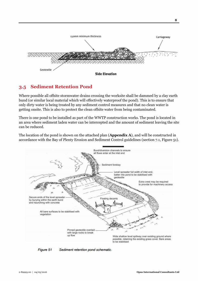
3.5 Sediment Retention Pond
Where possible all offsite stormwater drains crossing the worksite shall be dammed by a clay earth
bund (or similar local material which will effectively waterproof the pond). This is to ensure that
only dirty water is being treated by any sediment control measures and that no clean water is
getting onsite. This is also to protect the clean offsite water from being contaminated.
There is one pond to be installed as part of the WWTP construction works. The pond is located in
an area where sediment laden water can be intercepted and the amount of sediment leaving the site
can be reduced.
The location of the pond is shown on the attached plan (Appendix A), and will be constructed in
accordance with the Bay of Plenty Erosion and Sediment Control guidelines (section 7.1, Figure 51).

9
2-89993.00 | 04/05/2016 Opus International Consultants Ltd
The pond has a contributing catchment area of 0.621 ha, and dimensions as follows: 6.5m width,
20.5m length, 1.5m depth, for a total volume of 200m3. The pond will have a forebay with
dimensions as follows: 6.5m width, 3.0m length, 1m depth, for a total volume of 20m3.
Generally the pond shall be constructed in accordance with the Bay of Plenty Erosion and Sediment
Control guidelines (section 7.1). This will involve:
Heavy compaction.
A geotextile/filter cloth pinned (0.5m centres) over the bund.
No bund should be higher than 2m.
4 Dust Control
Dust is a major issue at construction sites, it has environmental, safety and health risks associated
with the works. The main effects are health hazards for affected residents, damage to trees, and
safety for road users as well as general nuisance to the public. The construction methods employed
will ensure that dust generation is mitigated and managed at all times to ensure safety to road
users is not impacted.
4.1 Method/Procedure
The Contractor will ensure that dust in kept to a minimum and is compliant with any resource
consent conditions at all times. The following measures will be allowed for during the construction
period:
Monitoring, testing and compliance as per any Resource Consent conditions
Sprinkler systems throughout the construction site
Water carts will be available on site at all times
Matting, mulching, Hydroseeding
Stabilisation of stockpiling areas and bunds if required
Water sourced from an approved supply, all local restrictions will be adhered to.
The Contractor will obtain daily forecasts and circulate to appropriate staff. Dust control
measures will be instigated if dry, windy conditions are forecast.
Binding agents and dust suppressant additives are to be available if required.
Minimise exposed areas through construction staging.
Wind break fences are to be used if required.
4.2 Details of Dust Control
4.2.1 How water will be applied?
Sprinkler systems and water carts are to be operated by the contractor when and where required to
keep dust levels to an acceptable level, this includes after working hours, on weekends and
construction shutdown periods. It is up to the contractor to determine adequate sources of water
and appropriate permissions before establishment on site, including permits from the Rotorua
District Council for the use of water from the municipal water supply if required.
10
2-89993.00 | 04/05/2016 Opus International Consultants Ltd
4.2.2 The use and access to binding agents/dust suppressants for use in the
water carts or sprinkler systems
No binding agents or dust suppressant additives are proposed to be used in the water used for dust
control at this stage. Although access to these items will be identified by the contractor for use if
required.
4.2.3 The erection of a sign displaying a 24-hour contact telephone number
for the site contractor for complaints
The contractor shall supply and erect a sign at the entrance to the site from SH30. The sign must
display the project name, contractor’s name, and the words: “complaints or comments”, and
contact phone number for the contractor. This number must be manned 24hrs a day, 7 days a
week.
4.2.4 The use of wind-break fencing in problem areas
Winds in Rotorua are generally light in comparison to much of New Zealand, and there are
generally lighter winds during the construction season than during the off seasons. If the
contractor deems it necessary, they may use wind break fencing in problem areas to mitigate dust
migration.
4.2.5 Covering exposed areas with durable temporary windshield cloth or
geotextile fabrics
All topsoil stockpiles and bunds will be sown with grass or covered with mulch as soon as
practicable. Biodegradable matting will be used to stabilise any exposed slopes until they can be
grassed or planted.
4.2.6 Other options to be taken should attempts to manage dust nuisance
be unsuccessful
If all measures mentioned above prove to be inadequate at suppressing the dust in certain
unforeseen conditions, then any or all of the following courses of action may be implemented:
Cease the movement and operation of all plant and machinery on the construction site until the
dust is under control and is able to be maintained at acceptable levels.
If it is safe to do so, re-task all workers onto implementing dust control measures.
Shut the site down with the exception of dust control work.
4.2.7 How will you prevent tracking of dust and sediment by vehicle
movement off the work site?
All haul roads will be stabilised which trucks can then run on without having to turn around on
exposed surfaces. Restricting the truck movements to the haul road will allow for concentrated dust
control efforts in maintaining the quality of the haul road and wetting if required.
Vehicle movements on site will be governed by speed restrictions which will among other things
assist in preventing dust generation. All site entrances are to be stabilised to ensure minimal dust
tracking off site via vehicle movements.

11
2-89993.00 | 04/05/2016 Opus International Consultants Ltd
5 Implementing the Plan (Methodology)
The contractor should work to the ESCP, or approved variations as the job progresses.
All super silt fences shall be checked at the commencement of each construction week and before
and after any significant rainfall events.
All clean water cutout diversion channels shall be checked at the commencement of each
construction week and before and after any significant rainfall events. The inverts and outlets shall
be checked for evidence of scour and erosion and rehabilitated if required. Remove accumulated
sediment as required.
The sediment retention pond shall be inspected and maintained at the commencement of each
construction week, and before and after any significant rainfall event to check for any accumulated
sediment which may cause overtopping. Discharge points shall be checked for signs of scouring and
if required further armouring or stabilisation shall be undertaken.
This ESCP may be amended prior to construction if suitable alternatives to the current plan arise
through consultation with the successful Contractor, or better options become evident during the
construction phase. Any changes sought will require approval and sign off from the Bay of Plenty
Regional Council

12
2-89993.00 | 04/05/2016 Opus International Consultants Ltd
Appendix A: Sediment and Erosion
Control Plan Drawing
>
>
>
>
>
>
>
>
>
>
>
>
>
>
>
>
>
>
>
>
>
>
>
>
>
>
>
>
>
>
>
>
>
>
>
>
>
>
>
>
>
>
>
>
>
>
>
>
>
>
>
>
>
>
>
>
>
>
>
>
>
>
>
>
>
>
>
>
>
>
>
>
>
>
>
>
>
>
>
>
>
>
>
>
>
>
>>
>
>
>
>
>
>
>
>
PROPOSED ACCESS ROAD
TEMPORARY ACCESS TRACK
DURING CONSTRUCTION
RUNOFF DIVERSION BUND
AND CHANNEL PROTECTED
WITH GEOTEXTILE
SUPER SILT FENCE
SUPER SILT FENCE
STABILISED ENTRANCEWAY
PROPOSED WASTE WATER
TREATMENT PLANT
PROPOSED INFILTRATION TRENCHES
STABLE, EROSION
PROOF OUTFALL
STABLE, EROSION
PROOF OUTFALL
STABLE, EROSION
PROOF OUTFALL
SEDIMENT RETENTION POND (SRP) WITH
FOREBAY AND LEVEL SPREADER.
SRP: 20.5m LONG X 6.5m WIDE X 1.5m DEEP
VOLUME = 200m³
FOREBAY: 3.0m LONG X 6.5m WIDE X 1.0m DEEP
VOLUME = 20m³
CATCHMENT: 0.621ha
200
100
5010
0mm
300
mm
Scales Project No. Sheet. No.
Project
Sheet
Revision
Original Sheet Size A1 [841x594] Plot Date 2016-05-09 at 1:48:41 p.m. Path G:\CLIENTS\Rotorua Lakes Council\2-89993.00 Rotoma Rotoiti WWTP Resource Consent\4 Design\Drawings\(C)Civil\+Civil3D\2-89993.00_C01.dwg C01(A)
Drawn
Approved Approved Date
Rotorua Office PO Box 1245Rotorua 3040New Zealand
+64 7 343 1400
DRAWING IN PROGRESS
PLOTTED ON 2016-5-9 AT 1:48 p.m.
ROTORUA LAKES COUNCIL1438 STATE HIGHWAY 30 ROTORUAROTOMA ROTOITI WWTP RESOURCE CONSENT
EROSION AND SEDIMENT CONTROL PLANWASTE WATER TREATMENT PLANT
PRELIMINARY
2-89993.00 C01 A
J F N R 05/05/2016
J F 1:500 (A1) 1:1000 (A3)
Designed
1:1
0 2010 30 7040 50 60 80 90 100
mm
@ A1
@ A31:2
Approved Revision DateRevision Amendment


