Drywall Suspension System
Set Your Design Apart
Drywall Suspension System
Drywall Suspension System

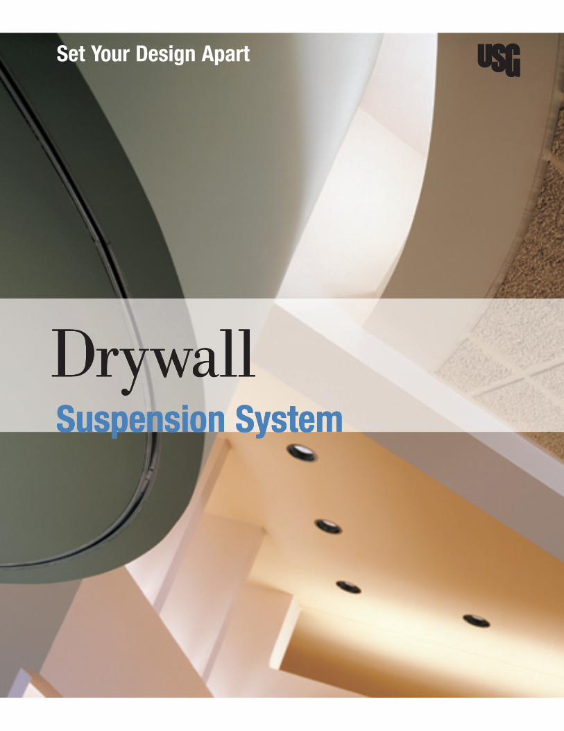
Drywall ceilings take a dramatic new shape with the USG drywall suspension system. This advanced system is pre-engineered to simplify planning and construction, ensuring that your design looks as good in real life as in your original concept.
Offices
Lobbies
Conference Rooms
Schools
Retail
Hospitality
Entertainment
One System, Endless PossibilitiesOne System, Endless Possibilities

56 USGDrywallSuspensionSystem
C. Attachgypsumpanelstothesuspensionsystemmainrunners,crossteesandcrosschannelswithconventionalgypsumpanelfasteners(No.6TypeSHiLobuglehead,self-drilling,self-tappingsteelscrews)spaced8o.c.atperipheryofgypsumpanelsandlocated3/8infrompaneledgesandspaced12o.c.inthefield.Drivefastenersinfieldofpanelsfirst,workingtowardendsandedges.Holdpanelsinfirmcontactwithframingwhiledrivingfasteners.Drivefastenerheadsslightlybelowsurfaceofgypsumpanelsinauniformdimplewithoutbreakingfacepaper.(SeeGypsumPanelandAccessoriesSpecificationSA92709250).
D. Installtrimatallinternalandexternalanglesformedbytheintersectionofpanelsurfacesorotherdissimilarmaterials.Applycornerbeadtoallverticalorhorizontalexternalcornersinaccordancewithmanufacturer’sdirections.Ceilingsnote:SeeDrywall/SteelFramedSystemsSpecificationsSA92309250USG-3.Spacingofdrywallgridisdesignedtosupportonlythedeadload.Heavyconcentratedloadsshouldbeindependentlysupported.Lightingfixturesortroffers,airventsandotherequipmentshouldbeseparatelysupportedfromthestructure;gypsumpanelswillnotsupporttheseitems.Topreventobjectionablesaginnewgypsumpanelceilings,theweightofoverlaidunsupportedinsulationshouldnotexceed1.3psffor1/2thickgypsumpanelswithspacingof24o.c.;2.2psffor1/2thickgypsumpanels16o.c.framing,1/2Sheetrockinteriorgypsumceilingpanelson24o.c.framing,and5/8panels24o.c.;3/8gypsumpanelsmustnotbeoverlaidwithunsupportedinsulation.Avaporretardershouldbeinstalledinexteriorceilings,andplenumoratticspacesshouldbeproperlyvented.Duringperiodsofcoldordampweatherwhenapolyethylenevaporretarderisinstalledonceilingsbehindthegypsumpanelsitisimportanttoinstalltheceilinginsulationbeforeorimmediatelyafterinstallingthegypsumpanels.Failuretofollowthisproceduremayresultinmoisturecondensationinthebackofthegypsumpanelscausingsag.
E. Spray-texturedceilings:Wherewater-basedtexturingmaterialsoranyslow-dryingsurfacetreatmentareusedoversingle-layerpanels,maximumframespacingis16o.c.for1/2panelsappliedperpendiculartoframing.
3.05 A. ProvideaseparationinthesuspensionsystematexpansionjointsasshownonthedrawingsandcarrytheExpansionJoints jointthroughthegypsumpanels.Expansionjointsareinstalledbetweentwomainteestoseparatethesuspension
systemandallowformovementinlargeceilingareas.
3.06 A. ProvidecontroljointNo..093whichhasa3/32groundfordrywallandveneerplaster.CeilingareasshouldControlJoints notexceed2,500sq.ft.withperimeterrelief900sq.ft.withoutperimeterrelief.
Application Guide SpecificationsCurved Drywall Ceilings

The USG drywall suspension system allows you to create unique curved, domed, and conventional flat drywall ceilings. The system assembles quickly and easily for faster installation, reducing labor costs. System accessories and integrated straight and curved components offer easy transitions to vertical, horizontal, or curved surfaces. Plus, the USG drywall suspension system has a lifetime limited warranty when used with Sheetrock® brand gypsum panels.
User’s Guide
Pages
UnderstandYourSystem 2 Overview
Components
Accessories
DesignYourSystem 8 SystemApplications
SpecifyYourSystem 44 ApplicationGuideSpecifications
ForMoreInformation TechnicalService 800USG.4YOU
WebSite www.usg.com
� USGDrywallSuspensionSystem

Simplicity TheUSGdrywallsuspensionsystemisapre-engineereddrywallceilingsystemspecificallycreatedto
simplifythedesignandconstructionofflatandcurveddrywallceilings.Customcurvedmainteescombine
withourfamilyofstraightteestogiveyoutheabilitytodesignbreathtakingdrywallceilingssimply.
Savings Thisunique,pre-engineeredsystemcanreduceinstalledcostsupto40%versusconventionalcold-rolled
channelorsteelstuddrywallceilinginstallations.And,thesystemrequires12-gaugehangerwireinsteadof
9-gauge,allowingfasterinstallation.
Flexibility Usingstandardparts,drywallbarrelvaults,archways,valleys,waves,serpentines,anddomeseasily
transitiontoflatceilings,soffits,andacousticalceilingsuspensionsystems.Allmaintees(straightand
curved)canbefieldcuttospecificlengths.ThesystemisfullycompatiblewithmostUSGDonn®Brand
acousticalsuspensionsystems.Morethan30ULfire-rateddesignsareavailableforflatceilings.Thesystem
acceptsTypeFlightfixturesandTypeGlay-infixtures.
Quality USGdrywallsuspensionsystemcomponentscomewitha10-yearwarrantyandalifetimelimitedwarranty
whenyouuseSheetrock gypsumpanels.
Innovation TheUSGdrywallsuspensionsystemEstimatorisavailabletohelpyoudesigndomes,vaults,andother
curvedsurfaceselectronically.Thisintuitive,on-linetoolcaninstantlygenerateacompletebillofmaterials
anddetailedinstallationinstructionsbasedonthedimensionsyouinput.Formoreinformation,goto
www.usg.comandselectResources>OnlineTools.
AdditionalResources ForinformationaboutsystemsandmaterialscomplementarytotheUSGdrywallsuspensionsystem,seethefollowingUSGliterature:
Wall-to-Walldrywallsuspensionsystemforcorridorsandsmallrooms(AC3236)
TheGypsumConstructionHandbook(H17)
USGproductselectionguide(SA927)
Sheetrockgypsumpanelssubmittal(WB1473)
Interiorfinishingproductscatalog(J1424)
GuidetoachievingaLevel5finish(J1829)
Sheetrock®brandtuff-hiDe™primer-surfacersubmittal(J1613)
DrywallSuspension System
2 USGDrywallSuspensionSystem

System Benefits
TheUSGdrywallsuspensionsystemgivesyoudistinctadvantagesoverconventionaldrywallceilinginstallationbyprovidingintegralsystemcomponentsthatallowyoutodesignuniquedrywallceilings.
Maintees Heavy-duty,fire-ratedsystemsforallflatceilingapplicationsincreaseflexibility;availablein1-1/2and15/16facewidthforflatceilings,and1-1/2facewidthforcurvedceilings.
Main-teesplices Integralreversibleenddetailforflatceilingswithfast,locked-in connections.
Crosstees Quick-releaSe™clipforfasterinstallation;eliminateswiretying;removeswithouttools;speedsrework.
Knurled-facecomponents Easierscrewpenetrationonallcomponents.
Galvanizedsteel Suitableforinteriorandexteriorapplications.
Systemflexibility Easilytransitionsfromsoffits,flatandcurvedsurfaces;alsotransitionstoacousticalceilings.
ULdesigns Morethan30UL-listedfire-resistantdesigns(themostdesignsintheindustry)areavailable.
Lifetimelimitedwarranty Lifetimelimitedwarranty(30year;seeSC2102)onsuspensionsystemwhenusedwithSheetrockgypsumpanels.
Standard�0-yearwarranty 10-yearonsuspensionsystem.
AcceptsTypeForGfixtures Lower-costTypeGfixturescanbeusedinadrywallinstallation. �2-gaugewire Easiertoworkwiththanthe9-gaugewirecommonlyprovidedwithsys-
temsbyothermanufacturers.
DesignTools TheUSGdrywallsuspensionsystemisthefirstpre-engineered,patentedsystemdesignedforcreatingdomedceilings.Nowvaultsanddomesareeasiertospecifyandbuild—andinstallationtimeiscutalmostinhalf.Thenewon-lineUSGdrywallsuspensionsystemEstimatorhelpsyoucreateperfectdomedandvaultedceilingsofalmostanysize.
Estimator Becausewe’veeliminatedtheguessworkoffieldbending,youareassuredapreciselycurvedfinishedproductthatmeetsyourexactdesignrequirements.WiththeUSGdrywallsuspensionsystemEstimator,allcurvedpartsaretoyourspecificationstocutandfastentogetherquicklyandeasily.
Howitworks:GotoResources>OnlineToolsatwww.usg.comandclick“USGDrywallSuspensionSystemEstimator.”Simplyentertheinformationrequired—typeofceiling,dimensions,andotherconstructiondetails.TheEstimatorquicklygeneratesacompletebillofmaterialsneededforthejob,plusstep-by-step,illustratedinstallationinstructions.Seepage24ofthisbrochureformoreinformationonhowtocreatedomedceilings.
3 USGDrywallSuspensionSystem

11/2"
11/2"
4 USGDrywallSuspensionSystem
System Components
RatedLoad
System ASTMClass Length Height ItemNo. Class 4HangerSpacingComponents
Straight DGLW HeavyDuty 12 1.617 DGLW26 16.0lbs./LF
Main
Tees
HeavyDuty 6to14 1.617 DGLW26s 16.0lbs./LF
DGL HeavyDuty 12 1-1/2 DGL26 16.0lbs./LF
HeavyDuty 7to14 1-1/2 DGL26s 16.0lbs./LF
Wall- DGW HeavyDuty 6to14,Custom 1.617 DGW26s ClassA 24.0lbs/LF
to-Wall
System
Straight
Tee
Cross DGLW — 2 1-1/2 DGLW224 —
Tees
— 26 1-1/2 DGLW2624 —
— 4 1-1/2 DGLW424 —
— 50 1-1/2 DGLW50 —
DGL — 2 1-1/2 DGL224 —
— 4 1-1/2 DGL424 —
— 8 1-1/2 DG824 ClassA —
CrossChannel — 4 7/8 DGCL4 7.4lbs./LF
Moldings — 12 1 DGWM24 — —
— 12 1-5/8 DGCM27� — —
1TheDGCM27moldingisforusewithDGLWteesonly.
11/2"
15/8"nom.
11/2"
15/16"
11/2"
15/16"
17/16"
7/8"
11/2"
1"
1"
15/8"
11/2"
15/8"nom.
5 USGDrywallSuspensionSystem
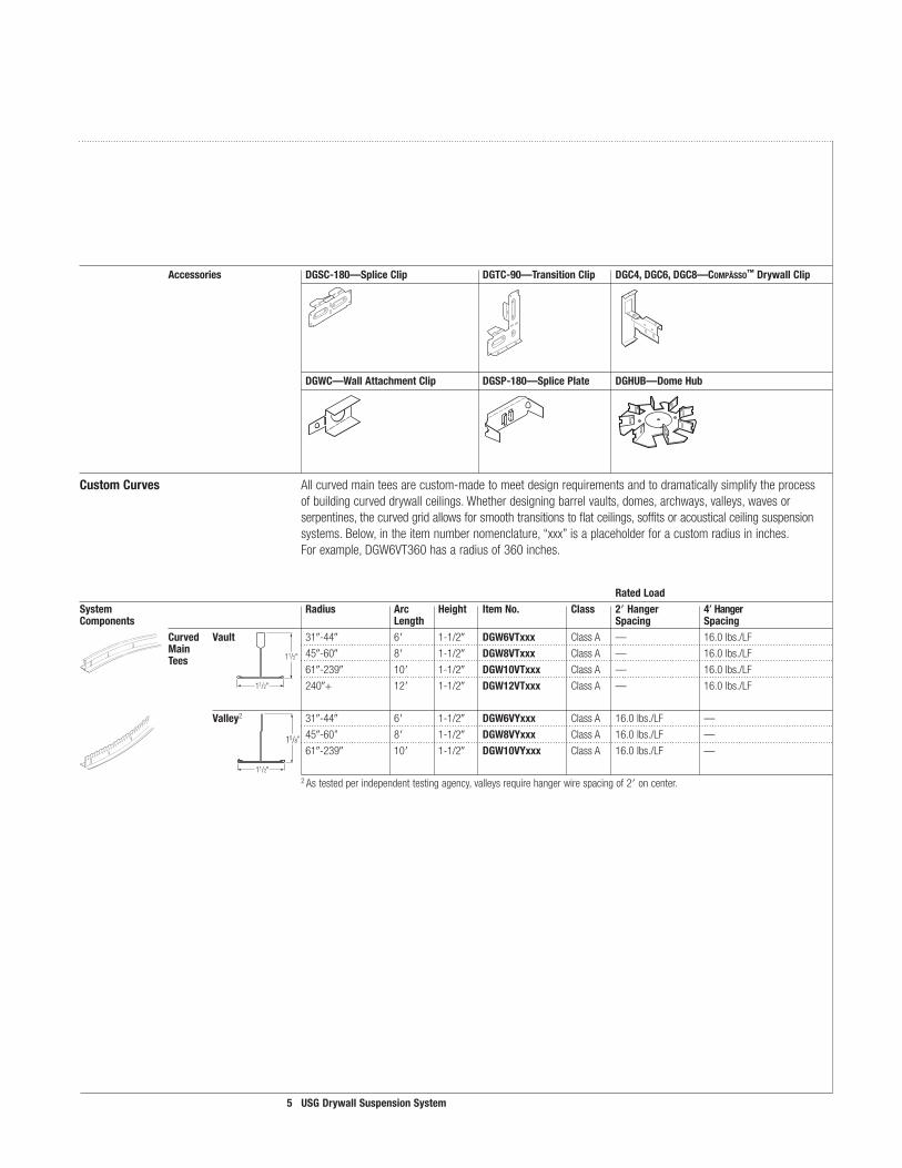
RatedLoadSystem Radius Arc Height ItemNo. Class 2Hanger 4HangerComponents Length Spacing Spacing Curved Vault 31-44 6 1-1/2 DGW6VTxxx ClassA — 16.0lbs./LF
Main 45-60 8 1-1/2 DGW8VTxxx ClassA — 16.0lbs./LF
Tees
61-239 10 1-1/2 DGW�0VTxxx ClassA — 16.0lbs./LF
240+ 12 1-1/2 DGW�2VTxxx ClassA — 16.0lbs./LF
Valley2 31-44 6 1-1/2 DGW6VYxxx ClassA 16.0lbs./LF —
45-60” 8 1-1/2 DGW8VYxxx ClassA 16.0lbs./LF —
61-239 10 1-1/2 DGW�0VYxxx ClassA 16.0lbs./LF —
2Astestedperindependenttestingagency,valleysrequirehangerwirespacingof2oncenter.
11/2"
11/2"
15/8"
11/2"
Accessories DGSC-�80—SpliceClip DGTC-90—TransitionClip DGC4,DGC6,DGC8—Compässo™DrywallClip
DGWC—WallAttachmentClip DGSP-�80—SplicePlate DGHUB—DomeHub
CustomCurves Allcurvedmainteesarecustom-madetomeetdesignrequirementsandtodramaticallysimplifytheprocessofbuildingcurveddrywallceilings.Whetherdesigningbarrelvaults,domes,archways,valleys,wavesorserpentines,thecurvedgridallowsforsmoothtransitionstoflatceilings,soffitsoracousticalceilingsuspensionsystems.Below,intheitemnumbernomenclature,“xxx”isaplaceholderforacustomradiusininches.Forexample,DGW6VT360hasaradiusof360inches.
6 USGDrywallSuspensionSystem
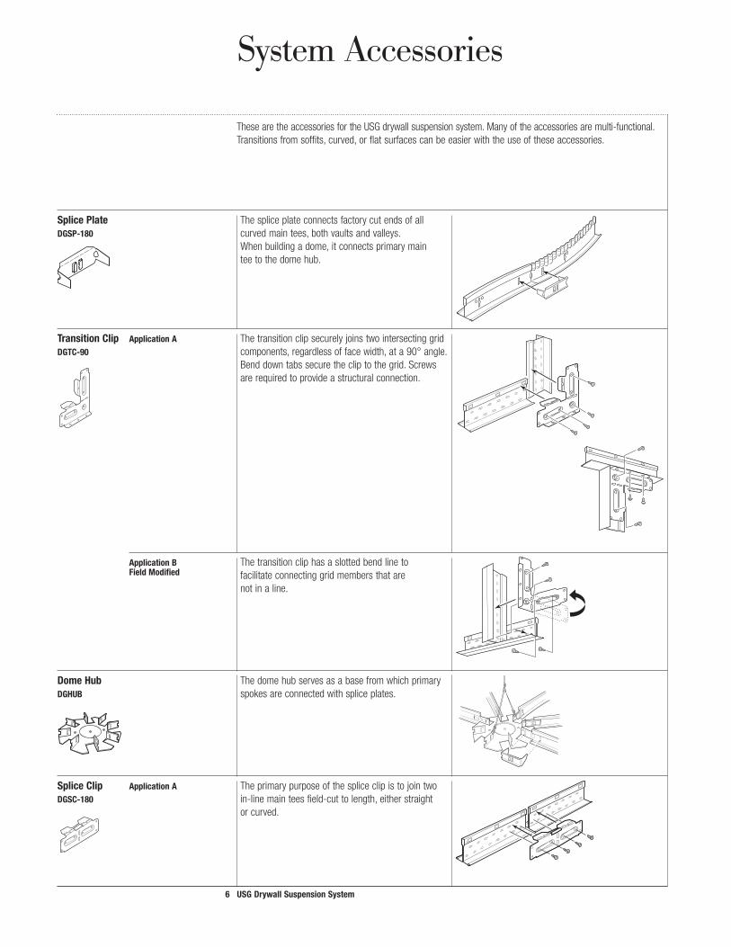
System Accessories
SplicePlate ThespliceplateconnectsfactorycutendsofallDGSP-�80 curvedmaintees,bothvaultsandvalleys. Whenbuildingadome,itconnectsprimarymain teetothedomehub.
TransitionClip ApplicationA ThetransitionclipsecurelyjoinstwointersectinggridDGTC-90 components,regardlessoffacewidth,ata90°angle. Benddowntabssecurethecliptothegrid.Screws arerequiredtoprovideastructuralconnection.
ApplicationB Thetransitioncliphasaslottedbendlineto FieldModified facilitateconnectinggridmembersthatare notinaline.
DomeHub ThedomehubservesasabasefromwhichprimaryDGHUB spokesareconnectedwithspliceplates.
SpliceClip ApplicationA TheprimarypurposeofthespliceclipistojointwoDGSC-�80 in-linemainteesfield-cuttolength,eitherstraight orcurved.
ThesearetheaccessoriesfortheUSGdrywallsuspensionsystem.Manyoftheaccessoriesaremulti-functional.Transitionsfromsoffits,curved,orflatsurfacescanbeeasierwiththeuseoftheseaccessories.

7 USGDrywallSuspensionSystem
SpliceClip ApplicationB AnothercommonuseofthespliceclipisjoiningDGSC-�80 twogridteesthatareintersectingoffmodule,such
asautilityopening.Thelinkjoiningthebenddowntabsontheclipiscutallowingittobefoldedontheslottedbendline.
ApplicationC Thespliceclipalsoisusedtoconnecttwomain FieldModified teesthatareinlinebutintersectingatanangle, suchasaflatceilingtransitioningtoavault.This applicationrequiresnotonlycuttingtheconnecting
linkbutalsoseparatingtheclipattheslottedbendline.Thetwohalvesarethenrejoinedwithapop-rivetorscrewthroughtheholesontheclipends.Usetopholeinclipforstraighttovaults.Usebottomholeinclipforstraighttovalleys.
Wall ThewallattachmentclipactsasaspacerbetweenAttachment thewallsurfaceandthewebofthegridwhencurvedClip mainteesneedtobesecuredtothewallatawallDGWC stud.Thispreventstwistingofthegridandinsures asoundinstallation.
Compässo™Clips compäSSo suspensiontrimclipsareavailabletomatchDGC4 DCC�0 4, 6, 8, 10 and12compäSSo trim.TheseclipsDGC6 DGC�2 areadjustableforboth1/2and5/8drywall.TheDGC8
twoportionsofthecliparepivotedtoaccommodatecompäSSo trimatanyangleinrelationtothegrid.

8 USGDrywallSuspensionSystem
A
9
B
9
A-�
75%
drywallmaintees
drywallcrosstees
channelmolding
12ga.hangerwires
SHEETROCKgypsumpanel
Flat Drywall Ceilings
– Main-teeandcross-teespacingisprovidedinthetableonpage30. – Seepages32-35forspecialrequirementsforfireratedassemblies.
Note:Theserenderingsanddetailsareprovidedforillustrativepurposesonlyandarenotasubstituteforcertifiedarchitecturalandengineeringdrawings,nordotheynecessarilyreflectnationalandlocalbuildingcoderequirements.Foradditionalinformation,seespecificationsonpage40orcallTechnicalServiceat1-800-USG-4YOU.
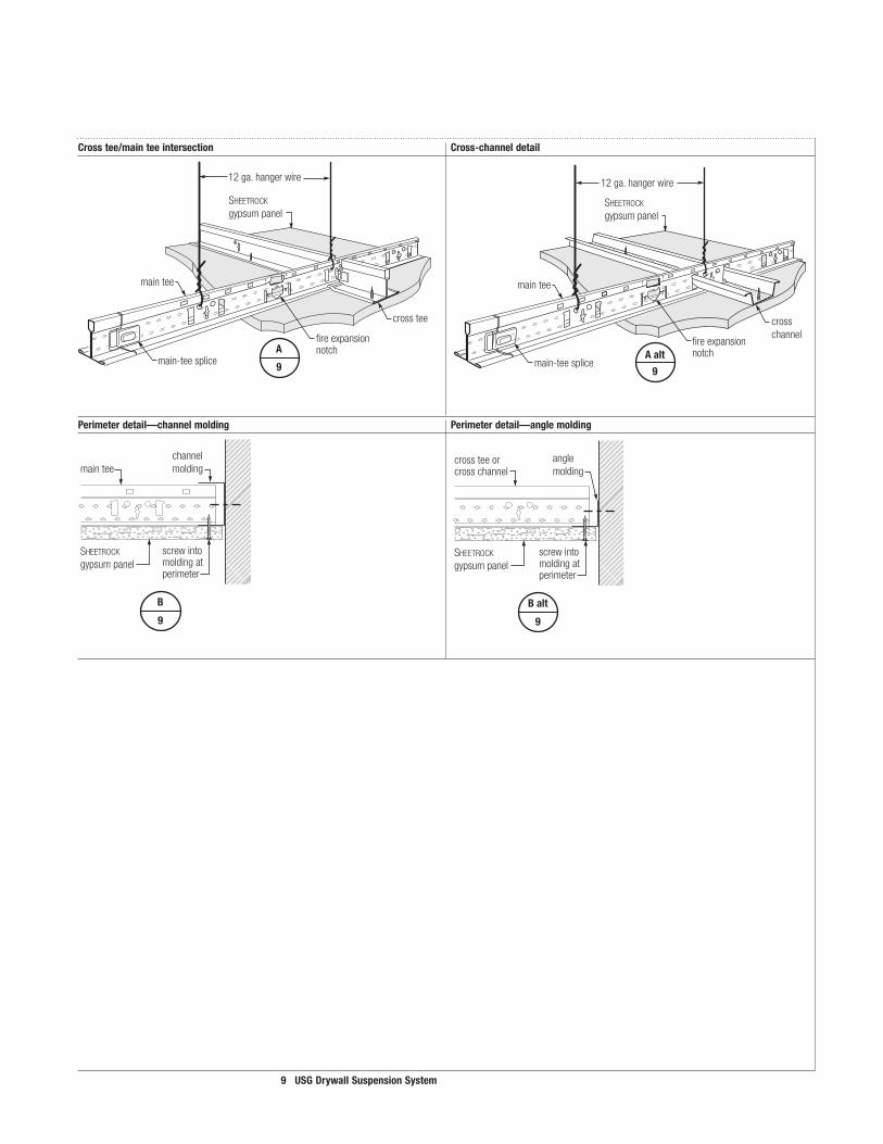
DrywallceilinginstallationusingtheUSGdrywallsuspensionsystemisupto50%fasterthancold-rolledchannelandhat-channelinstallation.Pre-engineeredcomponentsaredesignedformaximuminstallationspeed.Pre-indexedmain-teeholesmakemeasuring,aligning,andsquaringthesystemmucheasier.
9 USGDrywallSuspensionSystem
9
A
crosstee
main-teesplice
maintee
fireexpansionnotch
12ga.hangerwire
SHEETROCKgypsumpanel
Crosstee/mainteeintersection Cross-channeldetail
Perimeterdetail—channelmolding Perimeterdetail—anglemolding
crossteeorcrosschannel
screwintomoldingatperimeter
anglemolding
SHEETROCKgypsumpanel
Balt
9
fireexpansionnotch
12ga.hangerwire
SHEETROCKgypsumpanel
main-teesplice
maintee
crosschannel
9
Aalt
maintee
SHEETROCKgypsumpanel
channelmolding
screwintomoldingatperimeter
B
9

�0 USGDrywallSuspensionSystem
drywallmaintee
knurledchannelmolding
12ga.hangerwire
acousticalmaintee
acousticalcrosstees
acousticallay-inpanel
drywallcrosstees
acousticalmaintee
SHEETROCKgypsumpanel
C
��
D
��B
9
A-2
Transitions
ThenewUSGdrywallsuspensionsystemisfullycompatiblewithourDonn®brandDX®/DXL™,DXSS,DXW,andcentricitee™ acousticalsuspensionsystems,makingiteasytotransitionbetweenflatdrywallandacousticalceilings.Flushoroffsettransitionsarepossible.Additionalcrossteesarenecessaryatdrywalledgetoprovideadequatesupport(asshownonnextpage).
Note:Theserenderingsanddetailsareprovidedforillustrativepurposesonlyandarenotasubstituteforcertifiedarchitectural
andengineeringdrawings,nordotheynecessarilyreflectnationalandlocalbuildingcoderequirements.Foradditionalinformation,seespecificationsonpage40orcallTechnicalServiceat1-800-USG-4YOU.
Drywall to Acoustical Ceilings

�� USGDrywallSuspensionSystem
acousticalmaintee
drywallmaintee
drywallcrosstee
crosstee
acousticalcrosstee
spliceclip
SHEETROCKgypsumpanel
drywallbead
C
��
11/2"9/16"
or15/16"
4" 3"
SHEETROCKgypsumpanel
acousticalpanel
crosstee
drywallmaintee
acousticalmaintee
Calt
��
drywallbead
drywallmaintee
drywallcrosstee
additionaldrywallcrosstee
2"to4"
acousticalmaintee
acousticalmaintee
acousticalceiling
drywallbead
drywallceiling
acousticalcrosstee
drywallcrosstee
acousticalcrosstee
SHEETROCK
gypsumpanel
acousticalpanel
D
��
maintee
SHEETROCKgypsumpanel
acousticalpanel
channelmolding
Dalt-�
��
Drywall-to-acousticaltransition—field-cutconnection Drywall-to-acousticaltransition
Planview
Drywall-to-acousticaltransition—factory-endconnection Flushtransition Standardoffset
tee
SHEETROCKgypsumpanel
acousticalpanel
channelmolding
Dalt-2
��
attachcrossteeswithmechanicalfasteners
additional2'drywallcrosstee(offmodule)attachwithmechanicalfasteners
acousticalmaintees 4'-0"acousticalcrosstees
2'-0"acousticalcrosstees
acousticalceiling
drywallceiling
lineofdrywall
extradrywallcrossteesgypsumpanelsupport-offmodule;attachtoadjacentslotsinmaintee
hangerwires
4'-0"drywallcrosstees
drywallmaintees
crosstee
crosstees
SHEETROCKgypsumpanel
E
�3
F
�3
F
�3
B
9
G
�3
H
�3
C-�
75%
�2 USGDrywallSuspensionSystem
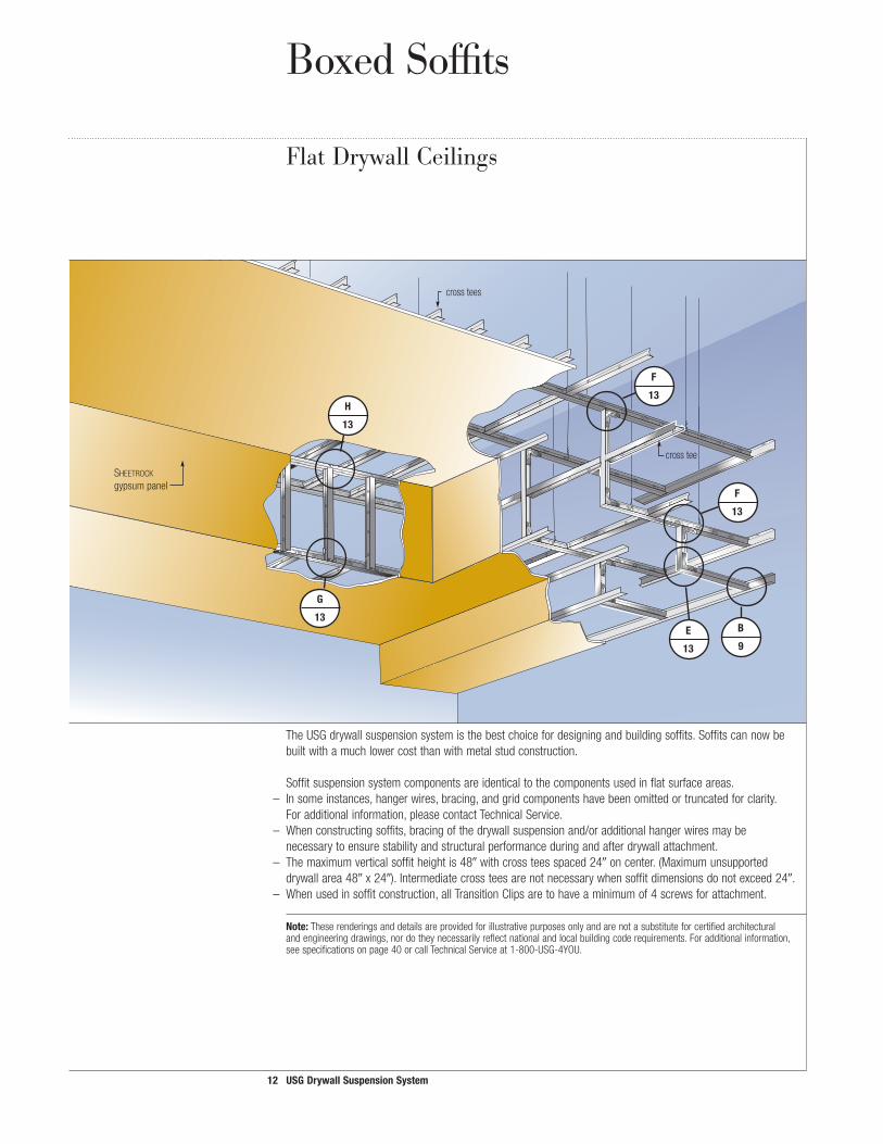
Boxed Soffits
Flat Drywall Ceilings
TheUSGdrywallsuspensionsystemisthebestchoicefordesigningandbuildingsoffits.Soffitscannowbebuiltwithamuchlowercostthanwithmetalstudconstruction.
Soffitsuspensionsystemcomponentsareidenticaltothecomponentsusedinflatsurfaceareas. – Insomeinstances,hangerwires,bracing,andgridcomponentshavebeenomittedortruncatedforclarity.
Foradditionalinformation,pleasecontactTechnicalService. – Whenconstructingsoffits,bracingofthedrywallsuspensionand/oradditionalhangerwiresmaybe
necessarytoensurestabilityandstructuralperformanceduringandafterdrywallattachment. – Themaximumverticalsoffitheightis48withcrossteesspaced24oncenter.(Maximumunsupported drywallarea48x24).Intermediatecrossteesarenotnecessarywhensoffitdimensionsdonotexceed24. – Whenusedinsoffitconstruction,allTransitionClipsaretohaveaminimumof4screwsforattachment.
Note:Theserenderingsanddetailsareprovidedforillustrativepurposesonlyandarenotasubstituteforcertifiedarchitecturalandengineeringdrawings,nordotheynecessarilyreflectnationalandlocalbuildingcoderequirements.Foradditionalinformation,seespecificationsonpage40orcallTechnicalServiceat1-800-USG-4YOU.
�3 USGDrywallSuspensionSystem
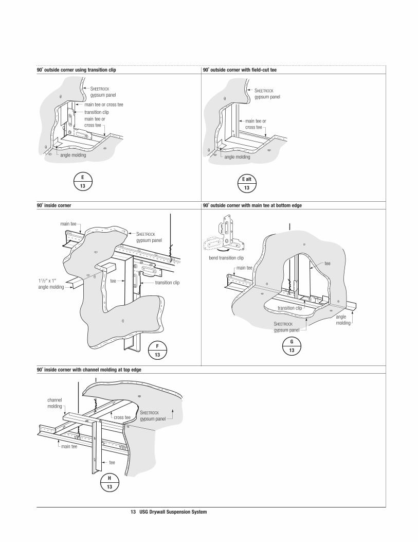
anglemolding
transitionclip
mainteeorcrosstee
mainteeorcrosstee
SHEETROCKgypsumpanel
E
�3
90˚outsidecornerusingtransitionclip 90˚outsidecornerwithfield-cuttee
channelmolding
tee
maintee
crossteeSHEETROCKgypsumpanel
H
�3
90˚insidecorner 90˚outsidecornerwithmainteeatbottomedge
90˚insidecornerwithchannelmoldingattopedge
anglemolding
mainteeorcrosstee
SHEETROCKgypsumpanel
Ealt
�3
transitionclip
maintee
anglemolding
tee
SHEETROCKgypsumpanel
G
�3
bendtransitionclip
transitioncliptee11/2"x1"anglemolding
SHEETROCKgypsumpanel
maintee
F
�3

�4 USGDrywallSuspensionSystem
maintee
12ga.hangerwire
crosstees
curvedmaintee
mainteesplice
transitionclip
SHEETROCK
gypsumpanelknurledchannelmolding
anglemolding
acousticalmaintee
acousticalcrosstees
acousticallay-inpanel
brace
J
�5
I
�5
K
�5
F-�
Curved Soffits
Designandbuildsoffitseasier,quickerandmoreeconomicallyusingtheUSGdrywallsuspensionsystem.
Constructcurvedsoffitswithcurvedmaintees.Createvaults,valleys,andcombinations,andshiftfromhorizontalorverticalstraightareaswithease.Foraddedflexibility,gridmemberscanbefield-cutandjoined.
– Insomeinstances,hangerwiresandbracinghavebeenomittedandcomponentstruncatedforclarity.Foradditionalinformation,pleasecontactTechnicalService.
– Whenconstructingcurvedsoffits,bracingofthedrywallsuspensionand/oradditionalhangerwiresmaybenecessarytoensurestabilityandstructuralperformanceduringandafterdrywallattachment.Seepage19forhangerwirespacingrequirements.
– Themaximumverticalsoffitis48withcrossteesspaced24oncenter.(Maximumunsupporteddrywallarea48x24).Intermediatecrossteesarenotnecessarywhensoffitdimensionsdonotexceed24.
– AllTransitionorSpliceClipsaretohaveaminimumof4screwsforattachment.
Note:Theserenderingsanddetailsareprovidedforillustrativepurposesonlyandarenotasubstituteforcertifiedarchitecturalandengineeringdrawings,nordotheynecessarilyreflectnationalandlocalbuildingcoderequirements.Foradditionalinformation,seespecificationsonpage48orcallTechnicalServiceat1-800-USG-4YOU.
Curved Drywall Ceilings

�5 USGDrywallSuspensionSystem
crosstee
maintee
SHEETROCKgypsumpanel
modifiedtransitionclip
valleymaintee
angle(byothers)
J
�5
crosstee
maintee
SHEETROCKgypsumpanel
spliceclip
valleymaintee
I
�5
8"max.
48"max.
SHEETROCKgypsumpanel
transitionclip
acousticalpanel
bracingasrequired
channelmolding
K
�5
Curvedsoffittoboxedsoffit—valleytoflat Sectionthroughsoffitandacousticaltransition
Curvedsoffit—flattovalley
modifiedtransitionclip

main tees
angle molding
SHEETROCK gypsum panel
Corridors
TheUSGwall-to-walldrywallsuspensionsystemisdesignedtocreateconventionalflatdrywallceilingsincorridorsandsimilarspaceswithspansoflessthan14ft.Thisframingsolutioniseasiertoworkwiththanblackironandfurringchannelsordrywallstuds,andithelpstoreducelaborcosts.
Thesystemassemblesquicklyandeasily,framingnarrowerspacesefficientlyandwithaminimumofcomponents.Systemaccessoriesandintegratedstraightcomponentsoffereasytransitionstovertical,horizontal,orcurvedsurfaces.
Thewall-to-walldrywallsuspensionsystemincludes6,8,10,12and14double-web,rotarystitchedknurledtees,and12knurledanglemolding.TeesaretestedinaccordancewiththeuniformloadtestproceduresoutlinedinASTMStandardC635,andcertifiedbyanICBOlistedtestingagency.LoadsarelimitedtoL/240ofeachspan,perASTMC645.
Wall-to-Wall System
�6 USGDrywallSuspensionSystem
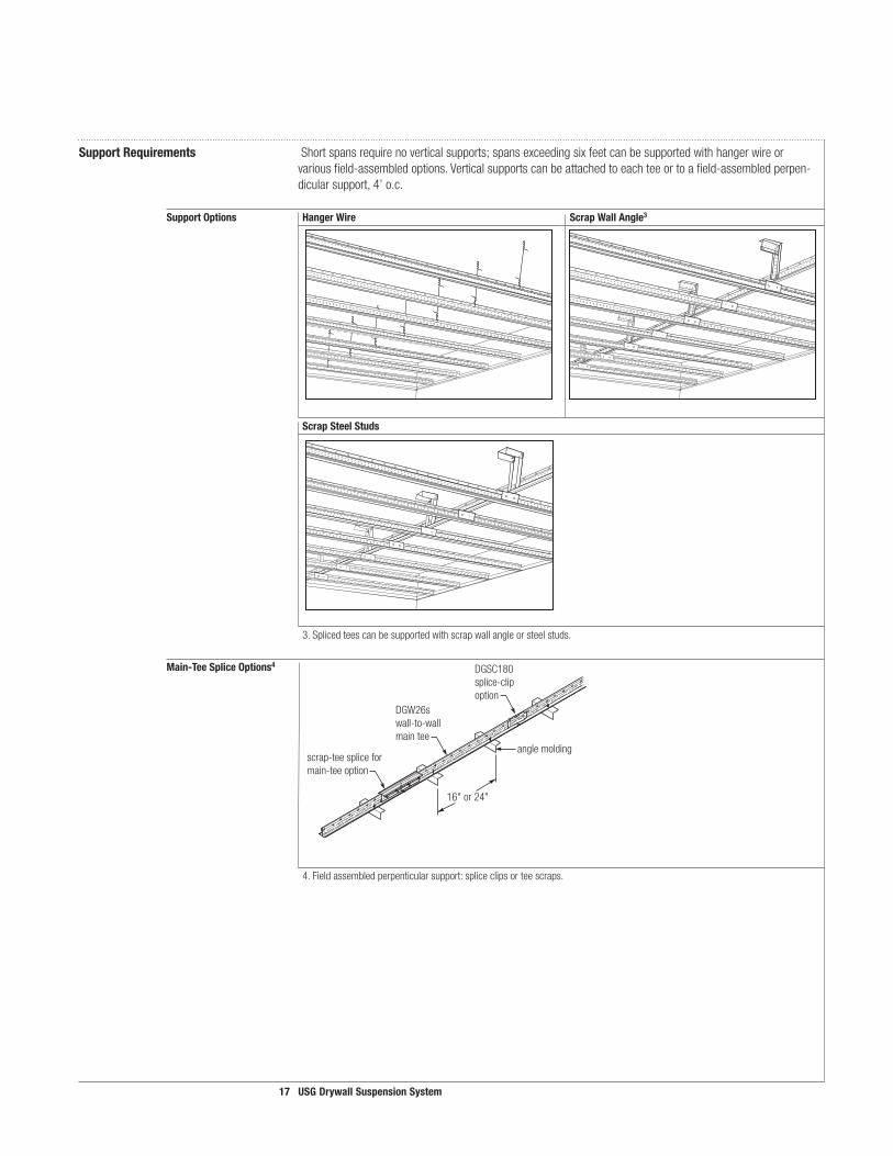
SupportRequirements Shortspansrequirenoverticalsupports;spansexceedingsixfeetcanbesupportedwithhangerwireorvariousfield-assembledoptions.Verticalsupportscanbeattachedtoeachteeortoafield-assembledperpen-dicularsupport,4’o.c.
SupportOptions HangerWire ScrapWallAngle3
ScrapSteelStuds
3.Splicedteescanbesupportedwithscrapwallangleorsteelstuds.
Main-TeeSpliceOptions4
4.Fieldassembledperpenticularsupport:spliceclipsorteescraps.
16" or 24"
angle molding
DGW26s wall-to-wallmain tee
scrap-tee splice for main-tee option
DGSC180 splice-clip option
�7 USGDrywallSuspensionSystem
�8 USGDrywallSuspensionSystem
L
�7
D-�
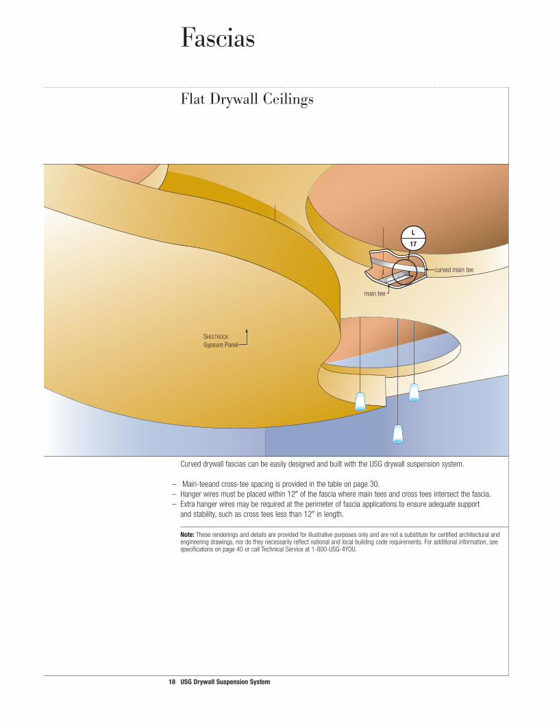
maintee
curvedmaintee
SHEETROCKGypsumPanel
Fascias
CurveddrywallfasciascanbeeasilydesignedandbuiltwiththeUSGdrywallsuspensionsystem.
– Main-teeandcross-teespacingisprovidedinthetableonpage30. – Hangerwiresmustbeplacedwithin12ofthefasciawheremainteesandcrossteesintersectthefascia. – Extrahangerwiresmayberequiredattheperimeteroffasciaapplicationstoensureadequatesupport
andstability,suchascrossteeslessthan12inlength.
Note:Theserenderingsanddetailsareprovidedforillustrativepurposesonlyandarenotasubstituteforcertifiedarchitecturalandengineeringdrawings,nordotheynecessarilyreflectnationalandlocalbuildingcoderequirements.Foradditionalinformation,seespecificationsonpage40orcallTechnicalServiceat1-800-USG-4YOU.
Flat Drywall Ceilings

�9 USGDrywallSuspensionSystem
Curveddrywallfascia(upto8max.)forflatceilings
L
�7
attachwithscrewortransclip
4"max.
12"max.
L-bead
curvedmainteetee
flexibledrywalltrim
Lalt
�7
attachwithscrewortransclip
attachwithscrew
supportbrace
8"max.
L-beadcurvedmaintees
teeflexibledrywalltrim
12"max.

20 USGDrywallSuspensionSystem
N
�9
Malt
�9
M
�9
C-�
78%
crossteesSHEETROCKgypsumpanel
12-ga.hangerwire
COMPÄSSOdrywallclip
COMPÄSSOtrim
UseUSG’scompäSSo suspensiontrimtofinishUSGdrywallsuspensionsystemceilings.
– Main-teeandcross-teespacingisprovidedinthetableonpage30. – Hangerwiresmustbeplacedwithin12ofthefasciawheremainteesandcrossteesintersectthefascia. – Extrahangerwiresmayberequiredattheperimetertoensureadequatesupportforcrossteeslessthan
12inlength.
Note:Theserenderingsanddetailsareprovidedforillustrativepurposesonlyandarenotasubstituteforcertifiedarchitecturalandengineeringdrawings,nordotheynecessarilyreflectnationalandlocalbuildingcoderequirements.Foradditionalinformation,seespecificationsonpage40orcallTechnicalServiceat1-800-USG-4YOU.
Fascias
Flat Drywall Ceilings

2� USGDrywallSuspensionSystem
CompässoTrimperpendiculartomainteeorcrosstee CompässoTrimparalleltomainteeorcrosstee
Viewfromabove Viewfromabove
COMPÄSSOdrywallclip
COMPÄSSOtrim
tee
SHEETROCK
gypsumpanel
N
�9
COMPÄSSOdrywallclip
COMPÄSSOtrim
tee
12"orless
SHEETROCKgypsumpanel
M
�9
Malt-�
�9
COMPÄSSOtrim
COMPÄSSOclip
tee
screw-attached
Malt-2
�9
COMPÄSSOtrim
COMPÄSSOcliptee
screw-attached

22 USGDrywallSuspensionSystem
maintee
knurledchannelmolding
12ga.hangerwire
splayedhangerwires
crosstees
curvedmaintee
main-teespliceplate
SHEETROCKgypsumpanels
P
2�
O
2�
B-�
Vaults
Createbarrelvaults,archways,valleys,andwaveswitheaseusingtheUSGdrywallsuspensionsystem.Integralclipsallowforasmoothtransitiontoflatceilings,soffits,oracousticalsuspensionsystems.
– Hangerwiresshallbespacedamaximumof48alongthearcofVaultsmaintees. – Additionalhangerwiresorbracingmaybenecessarytostabilizecurvedceilingsduringandafter
drywallattachment. – Atleast1hangerwireisrequiredwithin8ofacurvedmainteesplice. – Hangerwiresarerequiredwithin8onbothsidesofamodifiedspliceclipattachedtothenearest
hangerholes. – Atleast1hangerwireisrequiredwithin8ofatransitionclip. – Alldrywalljointsmustbeaminimumof12fromallmainteesplices. – Insomeinstances,hangerwires,bracingandgridcomponentshavebeenomittedortruncatedforclarity.
Foradditionalinformation,pleasecontactTechnicalService.
Note:Theserenderingsanddetailsareprovidedforillustrativepurposesonlyandarenotasubstituteforcertifiedarchitecturalandengineeringdrawings,nordotheynecessarilyreflectnationalandlocalbuildingcoderequirements.Foradditionalinformation,seespecificationsonpage48orcallTechnicalServiceat1-800-USG-4YOU.
Curved Drywall Ceilings

23 USGDrywallSuspensionSystem
Vaulttovault—factory-endconnection Vaulttovault—field-cut
Flattovaultwithanglegreaterthan90º Flattovaultwith90ºangle(notshowninprecedingperspective)
modifiedspliceclip
crosstee
curvedmaintee
spliceplate
SHEETROCKgypsumpanel O
2�
crosstee
crossteemaintee
SHEETROCKgypsumpanel
modifiedspliceclip
anglemolding
P
2�
crosstee
anglemolding
maintee
SHEETROCKgypsumpanel
transitionclip
curvedmaintee
crosstee
Q
2�
crosstee
curvedmaintee
spliceclip
SHEETROCKgypsumpanel Oalt
2�

24 USGDrywallSuspensionSystem
R
23
T
23
S
23
U
23
E-2
maintee
12ga.hangerwire
splayedhangerwires
crosstees
curvedmaintee
spliceclip
SHEETROCKgypsumpanels
Vaults and Valleys
Curved Drywall Ceilings
TheUSGdrywallsuspensionsystemsimplifiescurveddrywallceilingdesign.Itmakescreatingvaultsandvalleyseasier.
– Hangerwiresshallbespacedamaximumof48alongthearcVaultsmaintees. – Hangerwiresshallbespacedamaximumof24alongthearcofValleymaintees. – Additionalhangerwiresorbracingmaybenecessarytostabilizecurvedceilingsduringandafter
drywallattachment. – Atleast1hangerwireisrequiredwithin8ofastandardcurvedmainteesplice. – Hangerwiresarerequiredwithin8onbothsidesofamodifiedspliceclipattachedtothenearest
hangerholes. – Atleast1hangerwireisrequiredwithin8ofatransitionclip. – Alldrywalljointsmustbeaminimumof12fromallmainteesplices. – Insomeinstances,hangerwires,bracingandgridcomponentshavebeenomittedortruncatedforclarity.
Foradditionalinformation,pleasecontactTechnicalService.
Note:Theserenderingsanddetailsareprovidedforillustrativepurposesonlyandarenotasubstituteforcertifiedarchitecturalandengineeringdrawings,nordotheynecessarilyreflectnationalandlocalbuildingcoderequirements.Foradditionalinformation,seespecificationsonpage48orcallTechnicalServiceat1-800-USG-4YOU.
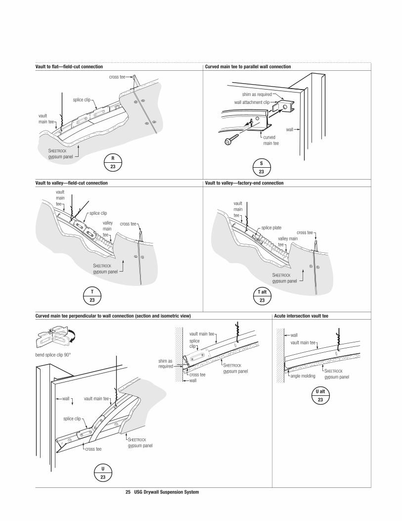
25 USGDrywallSuspensionSystem
cross tee
vault main tee
valleymain tee
splice clip
SHEETROCK gypsum panel
T
23
curvedmaintee
wall
wallattachmentclip
shimasrequired
S
23
spliceclip
vaultmaintee
SHEETROCKgypsumpanel
crosstee
shimasrequired
spliceclip
wall
vaultmaintee
SHEETROCKgypsumpanel
crosstee
wall
U
23
crosstee
vaultmaintee
SHEETROCKgypsumpanel
spliceclip
R
23
spliceplate
SHEETROCKgypsumpanel
crosstee
vaultmaintee
valleymaintee
Talt
23
Vaulttovalley—field-cutconnection Vaulttovalley—factory-endconnection
Curvedmainteeperpendiculartowallconnection(sectionandisometricview) Acuteintersectionvaulttee
vaultmaintee
SHEETROCKgypsumpanelanglemolding
wall
valleymaintee
SHEETROCKgypsumpanelanglemolding
wallvalleymaintee
SHEETROCKgypsumpanel
anglemolding
wall
vaultmaintee
SHEETROCKgypsumpanel
anglemolding
wall
Ualt
236alt2
E-2
6alt3
E-2
6alt4
E-2
Vaulttoflat—field-cutconnection Curvedmainteetoparallelwallconnection
bendspliceclip90°

26 USGDrywallSuspensionSystem
W
25
X
25
V
25
L
�7
primaryspoke
secondaryspoke
crosstee
Domes
TheUSGdrywallsuspensionsystemofferspre-engineeredsolutionsfordomeceilings.Itprovidesalow-costalternativetolabor-intensivesystemssuchasconventionalfield-benthat-channelsteelandblack-ironsuspensions.Usingthepre-fabricatedhubandpre-formedcurvedtees,constructingdomeshasneverbeeneasier.TheUSGdrywallsuspensionsystemEstimatormakesitsimplertobuildthedomewithfinishingoptionsrangingfromplasteranddrywalltopre-engineeredGRGpanels.
– Hangerwiresshallbespacedamaximumof32alongeachspoke. – Additionalsecondaryspokesarerequiredwhenspacingbetweenprimaryspokesexceeds48. – Hangerwiresarerequiredatbothendsofallsecondaryspokes. – Crossteesarerequired16o.c.maximum.
Curved Drywall Ceilings

27 USGDrywallSuspensionSystem
Hubandprimaryspokes Firstheaderandsecondaryspokes Secondheaderandsecondaryspokes
Crosstees Lathandplasterfinish
Detail�:Top-connectorspokehub Detail2:Header-to-spokeconnection
Detail3:Secondaryspokeconnection
W
25
primaryspoke
topview
removeinfield
header
V
25
curvedprimaryspoke
domehub
spliceplate
X
25
secondaryspoke
header

28 USGDrywallSuspensionSystem
drywallmaintees
drywallcrosstees
knurledchannelmolding
12-ga.hangerwires
SHEETROCKgypsumpanel
E-�
Z
27
Zalt
27
Y
26
Utility Interfaces
TheUSGdrywallsuspensionsystemeasilyaccommodatesconventionallightfixtures,accessdoors,orHVACceilingdiffusers.
Note:Theserenderingsanddetailsareprovidedforillustrativepurposesonlyandarenotasubstituteforcertifiedarchitecturalandengineeringdrawings,nordotheynecessarilyreflectnationalandlocalbuildingcoderequirements.Foradditionalinformation,seespecificationsonpage40orcallTechnicalServiceat1-800-USG-4YOU.
Accessdoor Accessdoor
crosstees
accessdoor
off-modulecrosstee
maintee
16"
16" 24"
24"
16"
16"
16"
1"x19/16"x1"knurledchannelmolding
SHEETROCK
gypsumpanel accessdoor(byothers)
spliceclip
Y
26
Flat Drywall Ceilings
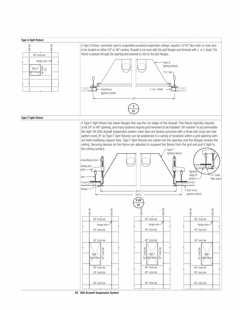
29 USGDrywallSuspensionSystem
ATypeGfixture,commonlyusedinsuspendedacousticalsuspensionceilings,requires15/16-facemainorcrossteestobelocatedoneither24or48centers.DrywalliscutevenwiththegridflangesandtrimmedwithJ-orL-bead.Thefixtureispassedthroughtheopeningandloweredtorestonthegridflanges.
ATypeFlightfixturehaslowerflangesthatcapthecutedgesofthedrywall.Thisfixturetypicallyrequiresafull24or48opening,andmanysystemsrequiregridmemberstobeinstalled“off-module”toaccommodatethelight.AllUSGdrywallsuspensionsystemmainteesarefactory-punchedwithathree-slotcrossteeholepatternevery8soTypeFlightfixturescanbepositionedinavarietyoflocationswithinagridopeningwith-outfield-modifyingsupporttees.TypeFlightfixturesareraisedintotheopeninguntiltheflangescontacttheceiling.Securingdevicesonthefixtureareadjustedtosuspendthefixturefromthegridandpullittighttotheceilingsurface.
TypeGlightfixture
TypeFlightfixture
48" cross tee
24" cross tee
main
tee
main
tee
hanger wire
Type Glight fixture 15/16"tee
TypeGlightingfixture
SHEETROCK
gypsumpanelJ-orL-bead
24"
Z
27
tee
flange
swingarmjack
mountingscrew
TypeFlightingfixture
SHEETROCKgypsumpanel
241/4"253/4"
Zalt
27
Type Flight fixture
48" cross tee
48" cross tee
48" cross tee
48" cross tee
48" cross tee
48" cross tee
50" c
ross
tee
main
tee
main
tee
hanger wire
Type F light fixture
48" cross tee
48" cross tee
48" cross tee
48" cross tee
48" cross tee
hanger wire
48" cross tee
50" c
ross
tee
50" c
ross
tee
main
tee
main
tee
Type Flight fixture
48" cross tee
48" cross tee
48" cross tee
48" cross tee
48" cross tee
48" cross tee
50” c
ross
tee
main
tee
main
tee
hanger wire
3/4"widefillerpiece
taperededgeofboard

30 USGDrywallSuspensionSystem
AA
29
BB
29
G-�
60%
Utility Interfaces
Curveddrywallceilingscreateexcitinglightingdesignopportunities.Theinterfaceoflightfixtureswithcurvedceilingsurfacesrequirescarefuldesignconsideration.Stem-andcable-styleindirectanddirectlightchoicesarepossiblesolutions.Recessedflatsectionscanbebuiltintocurvedsectionstoaccommodatelightfixtures.Sconcesarealsoveryeffectivewithavaultedceiling.
Wheninstallingdownlightsinconcaveorconvexceilings,theapplicationofaflattrimringwillcauseagap.Thisgapwillvarydependingontheceilingradius,trimringdiameterandinstallationtolerances.Formoreinformation,consultTechnicalService.
Note:Theserenderingsanddetailsareprovidedforillustrativepurposesonlyandarenotasubstituteforcertifiedarchitecturalandengineeringdrawings,nordotheynecessarilyreflectnationalandlocalbuildingcoderequirements.Foradditionalinformation,seespecificationsonpage48orcallTechnicalServiceat1-800-USG-4YOU.
Curved Drywall Ceilings

3� USGDrywallSuspensionSystem
AA
29
crosstee
light-fixturemountingbracket
lightfixture
SHEETROCKgypsumpanel
BB
29
crossteelight-fixturemountingbracket
lightfixture
SHEETROCKgypsumpanel
Pendantfixture—vault Incandescentfixture—recessedflatceiling

32 USGDrywallSuspensionSystem
Applying Sheetrock Gypsum Panels
PanelSelector BoardThickness Maximum Maximum MaximumforFlatCeilings Main-Tee Cross-Tee/Channel �2-Ga.Wire On-CenterSpacing On-CenterSpacing On-CenterSpacing
1/4doublelayer,Sheetrock gypsumpanels 48 16 48
3/8doublelayer,Sheetrock gypsumpanels 48 16 48
1/2doublelayer,Sheetrockgypsumpanels 48 16 42
5/8doublelayer,Sheetrock gypsumpanels 48 24 36
3/4Sheetrock gypsumpanels 48 24 48
1/2Sheetrock interiorgypsumceilingpanels 48 24 48
1/2Sheetrock firecoDe® andfirecoDe Cpanels 48 16 48
5/8Sheetrock firecoDe andfirecoDe CPanels 48 24 48
5/8Sheetrock exteriorgypsumceilingpanels 48 24 48
1/2imperialgypsumbase 48 16 48
5/8imperialfirecoDe andfirecoDe Cgypsumbase 48 16 48
1/2fiberock®aQua-tough®interiorpanels 48 24 48
5/8fiberock aQua-toughinteriorpanels 48 24 48
1/2Durock®cementboard ContactTechnicalService
5/8Durockcementboard
Notes: – Radiuseddouble-layer1/4gypsumpanelswilltransitionto5/8flatgypsumceilings.Seepage8. – Forfire-ratedceilingapplications,seepages32-33andcontactTechnicalService. – Forexteriorceilingapplications,seepage34andcontactTechnicalService. – Forgypsumpanelweights,seeThe Gypsum Construction Handbook,page9(CentennialEdition). – Fordouble-layerceilingapplications,a12-ga.hangerwireisneededoneachcrossteewithin8in.ofthewall(forallcrossteeslon-
gerthan8"). – ForDurockcementboardapplications,contactTechnicalServiceat800USG.4YOU.
ExpansionJoints Atbuildingmovementandexpansionjointsprovideaseparationinthesuspensionsystemandinstallbacktobackmainteestoallowforbuildingmovement,expansion,andcontractioninlargeceilingareas.
ControlJoints Controljointsareusedtocontrolstresscausedbyexpansionandcontractionacrossthecontroljointinlargeceilingexpansesinbothdrywallandveneerplastersystems.Usecontroljoint093,whichprovidesa3/32groundfordrywallorveneerplasterforceilingareasthatexceed50(2500sq.ft.)withperimeterreliefand30(900sq.ft.)withoutperimeterrelief.Forfire-ratedceilings,controljointsshallnotoccurwithin12ofthefireexpansionnotch.Donotseparatesuspension:Usecontinuoussinglemaintees.
SpecialNote Locationofcontrolandexpansionjointsaretheresponsibilityofthedesignprofessional.Gypsumpanel surfacesshouldbeisolatedwithcontroljoints,caulk,orothermeanswhere: – Ceilingorsoffitabutsastructuralelement,column,partition,orotherverticalpenetration. – Constructionchangeswithinaplaneoftheceiling. – Ceilingdimensionsexceed50ineitherdirection(2500sq.ft.)withperimeterreliefor30(900sq.ft.)
withoutrelief. – Soffitexceeds30ineitherdirection. – Wingsof“L”,“U”and“T”shapedceilingsareasarejoined.
1/2"to1"SHEETROCKgypsumpanel
min.25-gaugefillerstrip(byothers)
maintees
1/2"
USG093controljoint
maintees
SHEETROCKgypsumpanel
Alifetimelimited(30-year)warrantyontheUSGDrywallSuspensionSystemisofferedwhenSheetrock BrandGypsumPanelsareused.TheUSGDrywallSuspensionSystemisengineeredtoprovidetheultimateindesignflexibilityandwillaccept1/4,3/8,1/2,5/8,and3/4gypsumpanelsforflatandcurvedceilingapplications.Veneerplasterapplicationsarealsoavailable.

33 USGDrywallSuspensionSystem
PanelSelector Singlepanel,L/240uniformload,single-spandesign.forWall-to-WallSystem Spacemain-teemembersasrequiredbyspananddesignload. BoardThickness 0Supports �Support 2Supports
Mid-Span,EachMainOr �/3Points,EachMainOr ToAPerpendicularSupport ToAPerpendicularSupport
1/2Sheetrock gypsumpanels upto7span 7-1to14span
5/8Sheetrock gypsumpanels upto6span 6-1to12span 12-1to14span
MaximumLoads Maximumspacingbetweenhangersand/orsupports.
Unsupported Mains Maximum Span Load
L/240,perASTMC645 4 16o.c. 18lbs./SF
24o.c. 12lbs./SF
5 16o.c. 9.2lbs./SF
24o.c. 6.1lbs./SF
6 16o.c. 5.3lbs./SF
24o.c. 3.6lbs./SF
7 16o.c. 3.4lbs./SF
24o.c. 2.2lbs./SF
L/360,perASTMC645 4 16o.c. 12lbs./SF
24o.c. 8lbs./SF
5 16o.c. 6.1lbs./SF
24o.c. 4.1lbs./SF
6 16o.c. 3.6lbs./SF
24o.c. 2.4lbs./SF
7 16o.c. 2.2lbs./SF
24o.c. 1.5lbs./SF
Applying Sheetrock Gypsum Panels
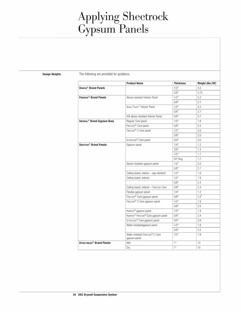
DesignWeights Thefollowingareprovidedforguidance.
ProductName Thickness Weight(lbs./SF)
DuroCk®BrandPanels 1/2 3.0
5/8 3.75
FiberoCk®BrandPanels Abuse-resistantInteriorPanel 1/2 2.2 5/8 2.7
aQua-tough™InteriorPanel 1/2 2.2
5/8 2.7
VHIabuse-resistantInteriorPanel 5/8 2.7
imperial®BrandGypsumBase RegularCorepanel 1/2 1.8
firecoDe®Corepanel 5/8 2.3
firecoDe®CCorepanel 1/2 2.0
5/8 2.5
ultracoDe®Corepanel 3/4 3.0
sheetoCk®BrandPanels Gypsumpanel 1/4 1.2
3/8 1.4
1/2 1.7
54long 1.7
Abuse-resistantgypsumpanel 1/2 2.2
5/8 2.7
Ceilingboard,interior–sagresistant 1/2 1.6
Ceilingboard,exterior 1/2 1.9
5/8 2.4
Ceilingboard,exterior–firecoDeCore 5/8 2.4
Flexiblegypsumpanel 1/4 1.2
firecoDe®Coregypsumpanel 5/8 2.2l
firecoDe®CCoregypsumpanel 1/2 1.9
5/8 2.5
humitek®gypsumpanel 1/2 1.9
humitek®firecoDe®Coregypsumpanel 5/8 2.4
ultracoDe®Coregypsumpanel 3/4 2.8
Water-resistantgypsumpanel 1/2 1.8
5/8 2.2
Water-resistantfirecoDe®CCore 1/2 1.9 gypsumpanel
struCtobase®BrandPlaster Wet 1 12
Dry 1 10
34 USGDrywallSuspensionSystem

35 USGDrywallSuspensionSystem
PanelSelector CurvedMainTees5 GypsumBoardThicknessOptions6
forCurvedCeilings Radius Arc CrossTee ItemNo. HangerWire Parallel7 Perpendicular7
Length Spacing Spacing Vault 31-44 6 8o.c. DGW6VTxxx 48 — 1/4flexdoublelayer8
45-60 8 8o.c. DGW8VTxxx 48 — 1/4doublelayer
61-91 10 8o.c. DGW10VTxx 48 1/4doublelayer8 1/4doublelayer
92-239 10 16o.c. DGW10VTxxx 48 1/4doublelayeror3/8 1/4doublelayeror3/8
240+ 12 16o.c. DGW12VTxxx 48 1/4doublelayeror1/2 1/4doublelayeror1/2
Valley 31-44 6 8o.c. DGW6VYxxx 24 — 1/4flexdoublelayer
45-60 8 8o.c. DGW8VYxxx 24 — 1/4doublelayer
61-91 10 8o.c. DGW10VYxxx 24 1/4doublelayer 1/4doublelayer
92-239 10 16o.c. DGW10VYxxx 24 1/4doublelayeror3/8 1/4doublelayeror3/8
5Allcurvedmainteesaretobespaced48o.c. 6Inamultiple-radiuscurvedceiling,selectpanelthicknessbasedonthesmallestradiusinthedesign. 7Seedrawingsbelow. 81/4gypsumpanelsmustbeappliedinadoublelayerfordurabilityandfinishing.
Parallel “Parallel”referstothelongwrappededgesofthegypsumpanelappliedparalleltothecurvedmaintees.ApplicationofDrywall
Perpendicular “Perpendicular”referstothelongwrappededgesofthegypsumpanelsappliedperpendiculartothecurvedApplication maintees.ofDrywall

36 USGDrywallSuspensionSystem
Fire-Rated Assemblies by UL Designs
Concrete/SteelDeck D501 2HR-R 5/8 Sheetrock firecoDeC N/A N/A Min.2ltwt.concreteonMin.W8x17FloorsOverSteelBeams 1-1/2HR-UR beams 2HR-UBR
D502 2HR-R&UR 5/8 Sheetrock firecoDeC 2x4 144sq.in. Min.2-1/2normalwt.concretetoppingon 2HR-UBR 1P-X2,1PC-AR,&WRC (24%) Min.W8x28beams
D503 2HR-R&UR 5/8 Sheetrock firecoDeC 6dia.incandescent N/A Min.2-1/2normalwt.concreteon2steel 2HR-UBR 4per100sq.ft deckonmin.W12x19beams.
Concrete/Expanded G523 2HR-R&UR 5/8 Sheetrock firecoDeC 2x4 144sq.in. Min.2-1/2normalwt.concretetoppingonLathFloorsOver 3HR-UBR 1P-X2 (24%) Min.8J2joistsandW10x21beamsSteelJoistsandBeams G524 2HR-R&UR 1/2 Sheetrock firecoDeC N/A 113sq.in. Min.2-3/4or2-1/2ltwt.ornormalwt. 2HR-UBR 1P-X2,1PC-AR,&WRC concretetoppingonmin.8or10Hambro
joists,respectively,andmin.W8x24beams
G525 2HR-R&UR 5/8 Sheetrock firecoDeC N/A 113sq.in. Min.3-1/2or3-1/4normalwt.concrete 2HR-UBR toppingonMin.8or10Hambrojoists,
respectively,andW8x24beams
G526 2HR-R&UR 1/2 Sheetrock firecoDeC 2x4 57sq.in Min.2-1/2normalwt.concretetoppingon 2HR-UBR (25%) Min.8J2joistsandW10x21beams
G527 2HR-R&UR 1/2 Sheetrock firecoDeC N/A N/A Min.2-1/2normalwt.concretetoppingon 3HR-UBR 1P-X2&1PC-AR Min.8J2joistsandW10x21beams
G528 1-1/2HR-R&UR 1/2 Sheetrock firecoDeC N/A N/A Min.2-1/2normalwt.concretetoppingon Min.10J2joists
G529 2HR-R&UR 1/2 Sheetrock firecoDeC 2x4 57sqin Min.2-1/2normalwt.orltwt.concrete 2or3HR-UBR (24%) toppingonMin.10J2joistsandW8x24beams
3HR&UR 1/2 Sheetrock firecoDeC 2x4 57sqin Min.3-1/4normalwt.concretetopping 3HR-UBR (24%) onMin.10J2joistsandW8x24beams
3HR-R&UR 5/8 Sheetrock firecoDeC 2x4 57sqin Min.2-3/4normalwt.concretetopping 3HR-UBR (24%) onMin.10J2joistsandW8x24beams
G531 2HR-R&UR 1/2 SheetrockfirecoDeC 1x1 144sq.in. Min.3-1/4normalwt.concrete 2HR-UBR (1%) Min.6D500steeljoist
1HR-R&UR 5/8 SheetrockfirecoDe 1x1 144sq.in. Min.2-1/2normalwt.concrete (1%) Min.6D500orD510steeljoist
G541 1HR-R&UR 5/8 SheetrockfirecoDeC 2x4 113sq.in. Min.3-1/2normalwt.concrete (24%) Min.7-3/16-deep,18-ga. steelC-joists
G546 1HR-R&UR 5/8 SheetrockfirecoDeC N/A N/A Min.2normalltwt.concrete 1HR-UBR light-gaugesteeltruss
G547 2HR-R&UR 1/2 SheetrockfirecoDeC 2x4 114sq.in. Min.2-1/2normalwt.concrete (24%) Min.8J2or10K1steeljoists
3HR-R&UR 5/8 SheetrockfirecoDeC 2x4 114sq.in. Min.3normalwt.concrete 3HR-UBR (24%) Min.8J2or10K1steeljoists
G551 1HR-UR 5/8 SheetrockfirecoDeC N/A N/A 1Levelrock,steeldeck,9-1/4-deepsteel oneor [email protected].,3-1/2insulation, twolayers [email protected].
PrecastConcreteFloors J502 2HR-U&UR 5/8 Sheetrock firecoDeC NA NA Min.2normalwt.concreteslab 3HR-R&UR 5/8 Sheetrock firecoDeC NA NA Min.2-3/4normalwt.concreteslab
WoodJoists L211 2HR-UR 1/2 Sheetrock firecoDeC 1x4(12%) 576sq.in.. T&Gorplywood(see6alternatives)over 75minfinishrating 2x2(16%) subflooron2x10joists@16oc,plus 2x4(24%) P237-ceilingconst. 20x48(20%)
L502 1HR-UR 1/2 Sheetrock firecoDeC N/A N/A T&Gorplywood(see14alternatives) 22minfinishrating 2P-X2,1PC-AR,&WRC [email protected].
L508 1HR-UR 5/8 SheetrockfirecoDeC N/A N/A T&Gorplywoodon4x10or 29minfinishrating 1P-X1,2P-X2,2PC-AR,SCX, DBL2x10joists SYX,&WRX
Flat Drywall Ceilings
Floor/Ceiling UL Assembly Board WallboardCore FixtureSize Max. AssemblyConstruction Design Rating* Thick. Type (%ofFixtures) DuctArea Details No. per�00sf
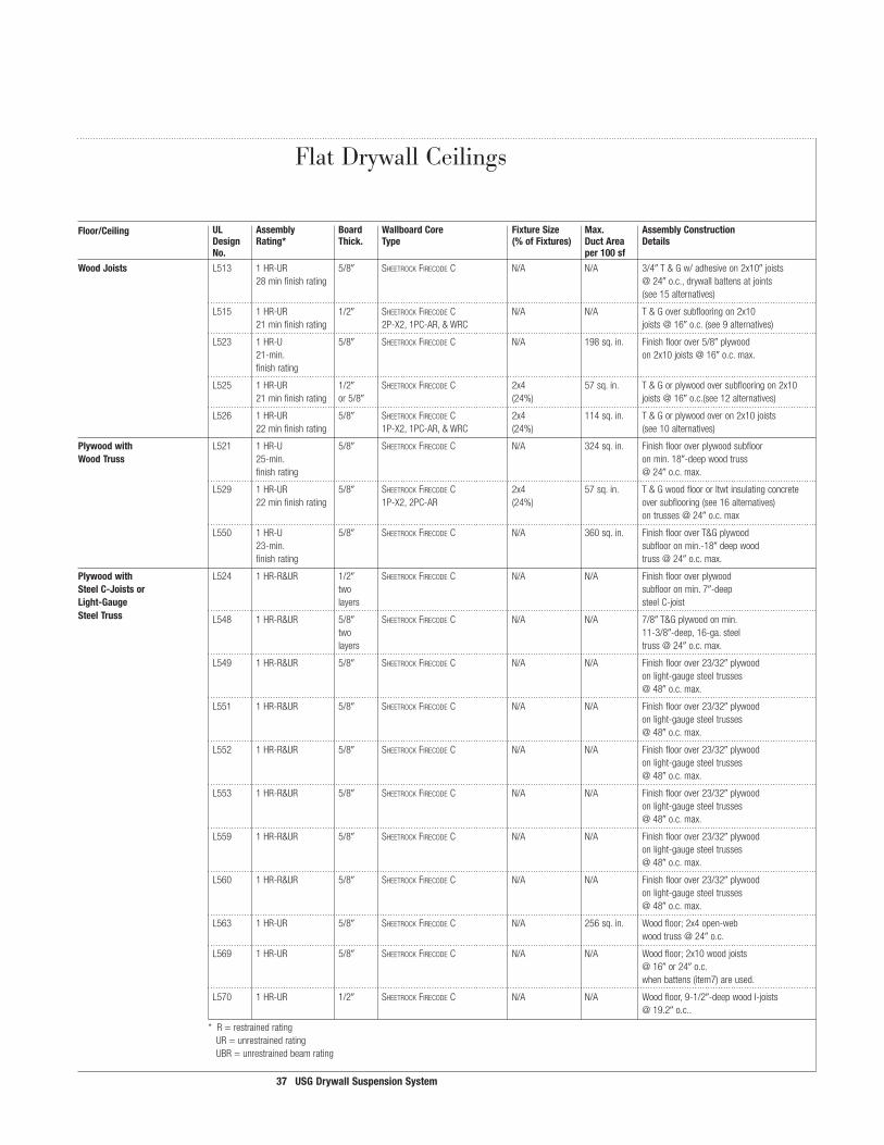
37 USGDrywallSuspensionSystem
WoodJoists L513 1HR-UR 5/8 Sheetrock firecoDeC N/A N/A 3/4T&Gw/adhesiveon2x10joists 28minfinishrating @24o.c.,drywallbattensatjoints (see15alternatives)
L515 1HR-UR 1/2 Sheetrock firecoDeC N/A N/A T&Goversubflooringon2x10 21minfinishrating 2P-X2,1PC-AR,&WRC [email protected].(see9alternatives)
L523 1HR-U 5/8 SheetrockfirecoDeC N/A 198sq.in. Finishfloorover5/8plywood 21-min. [email protected]. finishrating
L525 1HR-UR 1/2 Sheetrock firecoDeC 2x4 57sq.in. T&Gorplywoodoversubflooringon2x10 21minfinishrating or5/8 (24%) [email protected].(see12alternatives)
L526 1HR-UR 5/8 Sheetrock firecoDeC 2x4 114sq.in. T&Gorplywoodoveron2x10joists 22minfinishrating 1P-X2,1PC-AR,&WRC (24%) (see10alternatives)
Plywoodwith L521 1HR-U 5/8 SheetrockfirecoDeC N/A 324sq.in. FinishflooroverplywoodsubfloorWoodTruss 25-min. onmin.18-deepwoodtruss finishrating @24o.c.max.
L529 1HR-UR 5/8 Sheetrock firecoDeC 2x4 57sq.in. T&Gwoodfloororltwtinsulatingconcrete 22minfinishrating 1P-X2,2PC-AR (24%) oversubflooring(see16alternatives) [email protected]
L550 1HR-U 5/8 SheetrockfirecoDeC N/A 360sq.in. FinishflooroverT&Gplywood 23-min. subflooronmin.-18deepwood finishrating [email protected].
Plywoodwith L524 1HR-R&UR 1/2 SheetrockfirecoDeC N/A N/A FinishflooroverplywoodSteelC-Joistsor two subflooronmin.7-deepLight-Gauge layers steelC-joistSteelTruss L548 1HR-R&UR 5/8 SheetrockfirecoDeC N/A N/A 7/8T&Gplywoodonmin. two 11-3/8-deep,16-ga.steel layers [email protected].
L549 1HR-R&UR 5/8 SheetrockfirecoDeC N/A N/A Finishfloorover23/32plywood onlight-gaugesteeltrusses @48o.c.max.
L551 1HR-R&UR 5/8 SheetrockfirecoDeC N/A N/A Finishfloorover23/32plywood onlight-gaugesteeltrusses @48o.c.max.
L552 1HR-R&UR 5/8 SheetrockfirecoDeC N/A N/A Finishfloorover23/32plywood onlight-gaugesteeltrusses @48o.c.max.
L553 1HR-R&UR 5/8 SheetrockfirecoDeC N/A N/A Finishfloorover23/32plywood onlight-gaugesteeltrusses @48o.c.max.
L559 1HR-R&UR 5/8 SheetrockfirecoDeC N/A N/A Finishfloorover23/32plywood onlight-gaugesteeltrusses @48o.c.max.
L560 1HR-R&UR 5/8 SheetrockfirecoDeC N/A N/A Finishfloorover23/32plywood onlight-gaugesteeltrusses @48o.c.max.
L563 1HR-UR 5/8 SheetrockfirecoDeC N/A 256sq.in. Woodfloor;2x4open-web [email protected].
L569 1HR-UR 5/8 SheetrockfirecoDeC N/A N/A Woodfloor;2x10woodjoists @16or24o.c. whenbattens(item7)areused.
L570 1HR-UR 1/2 SheetrockfirecoDeC N/A N/A Woodfloor,9-1/2-deepwoodI-joists @19.2o.c..
*R=restrainedrating UR=unrestrainedrating UBR=unrestrainedbeamrating
Floor/Ceiling UL Assembly Board WallboardCore FixtureSize Max. AssemblyConstruction Design Rating* Thick. Type (%ofFixtures) DuctArea Details No. per�00sf
Flat Drywall Ceilings

38 USGDrywallSuspensionSystem
DoubleCeiling P237 2-HR-R&UR 1/2 Sheetrock firecoDeC 1x4(12%), 576sq.in. Roofsystemonsteelroofdeck,min.fiberRoofAssemblies 2-HR-UBR 2x2(16%), [email protected] 2x4(24%), 20x48(20%)
P239 1-1/2HR-R&UR 1/2 Sheetrock firecoDeC 1x4(12%), 576sq.in. Roofcoveringofgypsumconcreteover 1-1/2HR-UBR 2x2(16%), USG�formboard,subpurlinsand12J3joists 2x4(24%), w/w6x16beam. 20x48(20%)
P241 2HR-R&UR 1/2 Sheetrock firecoDeC 1x4(12%), 576sq.in. Roofcoveringoveroverinsulatingconcrete 2x2(16%), onsteelroofdeckand10J3minjoists@ 2x4(24%), 48o.c. 20x48(20%)
MineralandFiber P501 1and2HR-R&UR 5/8 Sheetrock firecoDeC N/A N/A Roofcoveringovermineralandfiberboard BoardonBuildingUnits 2P-X2&2PC-AR onbuildingorprecastconcreteunits,14J5 orPrecastConcrete [email protected].
GypsumPlank, P506 1-1/2HR-R&UR 5/8 Sheetrock firecoDeC 2x4 57sqin Roofcoveringovermin&fiberboards.on InsulationBoard (24%) gypsumplanks,subpurlinsand12H5 [email protected].
P508 1HR-R&UR 5/8 Sheetrock firecoDeC 2x4 144sqin Roofcoveringovermin&fiberboards(seealt) 2P-X2,1PC-AR,&WRC (24%) gypwallboard.,steelroofdeck,10J4joists (min)@48o.c.
Insulating P507 1-1/2HR-R 5/8 Sheetrock firecoDeC 2x4 57sqin Roofcoveringonfoamedplasticinsulation, Concrete 1HR-UR (24%) Gypsumconcandformboards.onsubpurlins and10J4joists(min)@4o.c.
P509 1HR-R&UR 5/8 Sheetrock firecoDeC` 2x4 144sqin Roofcoveringonfoamedplasticinsulation, 1HR-R (24%) Gypsumconc.andformboards.onsubpurlins and10J4joists(min)@4o.c.
CorrugatedSteelDeck P510 1&1-1/2HR-R 1/2& Sheetrock firecoDeC 2x4 57sqin Roofcoveringoverinsulation(seealt)w/InsulatedBoardor &UR 5/8 (24%) ongypsumwallboardsteelroofdeck, FoamPlasticInsulation 10J4joists(min)@72o.c.max.
P513 1-1/2HR-R&UR 5/8 Sheetrock firecoDeC 2x4 144sqin Roofcoveringoninsulatingconcreteand (24%) foamedplasticovercorrugatedsteeldeck, [email protected].
P514 2HR-R&UR 5/8 Sheetrock firecoDeC 2x4 255sqin Roofcoveringoverinsulation(see9 (24%) alternatives),gyp.wallboardandsteeldeck,
P516 1HR-UR 5/8 Sheetrock firecoDeC NA NA MetalroofdeckpanelsonMin.8deep (2layers) C-or-Z-shapedpurlins@60max,glassfiber
insulationbetweenroofdeckpanelsandsteelroofpurlins,W-shapedbeam
P518 1HR-R&UR 1/2 SheetrockfirecoDeC N/A N/A Roofcoveringoversteeldeckonmin. 1HR-UB two min.8-deep,18-ga.steelC-joists layers @24o.c.max.
EngineeredSteel P515 1HR-R&UR 5/8 SheetrockfirecoDeC N/A N/A RoofcoveringovermineralandfiberboardOrWood two onsteelroofdeckoversteelrooftrussesRoofTruss layers @48o.c.max.
P521 2HR-R&UR 5/8 SheetrockfirecoDeC N/A N/A Roofcoveringoverfoamedplasticinsulation, two gypsumwallboard,steeldeckonlight-gauge layers [email protected].
P522 1HR-UR 5/8 SheetrockfirecoDeC N/A 196sq.in. Roofsystemover15/32plywoodonwood [email protected][email protected].
P523 1HR-R&UR 5/8 SheetrockfirecoDeC N/A N/A Roofsystemover23/32plywoodon [email protected].
Fire-Rated Assemblies by UL DesignsFlat Drywall Suspension Ceilings
Floor/Ceiling UL Assembly Board WallboardCore FixtureSize Max. AssemblyConstruction Design Rating* Thick. Type (%ofFixtures) DuctArea Details No. per�00sf
39 USGDrywallSuspensionSystem
8"max. 8"max.maintee
crossteedrywallbuttjoint
SHEETROCKgypsumpanel
extracrossteerequiredforfirerating
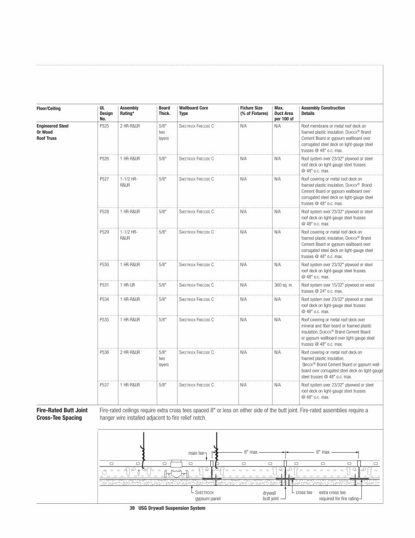
EngineeredSteel P525 2HR-R&UR 5/8 SheetrockfirecoDeC N/A N/A RoofmembraneormetalroofdeckonOrWood two foamedplasticinsulation,Durock®BrandRoofTruss layers CementBoardorgypsumwallboardover
corrugatedsteeldeckonlight-gaugesteel [email protected].
P526 1HR-R&UR 5/8 SheetrockfirecoDeC N/A N/A Roofsystemover23/32plywoodorsteel roofdeckonlight-gaugesteeltrusses @48o.c.max.
P527 1-1/2HR- 5/8 SheetrockfirecoDeC N/A N/A Roofcoveringormetalroofdeckon R&UR foamedplasticinsulation,Durock®Brand
CementBoardorgypsumwallboardovercorrugatedsteeldeckonlight-gaugesteel
P528 1HR-R&UR 5/8 SheetrockfirecoDeC N/A N/A Roofsystemover23/32plywoodorsteel roofdeckonlight-gaugesteeltrusses @48o.c.max.
P529 1-1/2HR- 5/8 SheetrockfirecoDeC N/A N/A Roofcoveringormetalroofdeckon R&UR foamedplasticinsulation,Durock®Brand
CementBoardorgypsumwallboardovercorrugatedsteeldeckonlight-gaugesteel
P530 1HR-R&UR 5/8 SheetrockfirecoDeC N/A N/A Roofsystemover23/32plywoodorsteel roofdeckonlight-gaugesteeltrusses @48o.c.max.
P531 1HR-UR 5/8 SheetrockfirecoDeC N/A 360sq.in. Roofsystemover15/32plywoodonwood [email protected].
P534 1HR-R&UR 5/8 SheetrockfirecoDeC N/A N/A Roofsystemover23/32plywoodorsteel roofdeckonlight-gaugesteeltrusses @48o.c.max.
P535 1HR-R&UR 5/8 SheetrockfirecoDeC N/A N/A Roofcoveringormetalroofdeckover mineralandfiberboardorfoamedplastic
insulation,Durock®BrandCementBoardorgypsumwallboardoverlight-gaugesteeltrusses@48o.c.max.
P536 2HR-R&UR 5/8 SheetrockfirecoDeC N/A N/A Roofcoveringormetalroofdeckon two foamedplasticinsulation, layers Durock®BrandCementBoardorgypsumwall-
P537 1HR-R&UR 5/8 SheetrockfirecoDeC N/A N/A Roofsystemover23/32plywwodorsteel roofdeckonlight-gaugesteeltrusses @48o.c.max.
Fire-RatedButtJoint Fire-ratedceilingsrequireextracrossteesspaced8orlessoneithersideofthebuttjoint.Fire-ratedassembliesrequireaCross-TeeSpacing hangerwireinstalledadjacenttofirereliefnotch.
Floor/Ceiling UL Assembly Board WallboardCore FixtureSize Max. AssemblyConstruction Design Rating* Thick. Type (%ofFixtures) DuctArea Details No. per�00sf

40 USGDrywallSuspensionSystem
Note:OnlySheetrock®brandexteriorceilingboard,fiberock®brandaQua-tough™sheathingandDurock®cementboardaresuitableforexteriorapplications.PleasecontactUSGTechnicalServiceformoreinformation.
Belowisachartindicatingthecomponentsandtheirspacing,whicharenecessarytoachievethedifferentULupliftclassifications.ContactTechnicalServiceforspecificinformationoncompressionposts,limitingple-numdepths,andconstructiondetailsforyourinstallation.
Designwindloadsvarywithgeographicregionandbuildingconditions,andmustbeestablishedbyaprofessionalengineerorarchitectofrecord.
FlatDrywallCeiling
Exterior Application Wind Load Data
Recommended Uplift Panel “A” MainTee “B” “C” “D”ComponentSpacing Load Type Max.MainTee Max.Cross Max.Hanger Max.Compression Spacing MemberSpacing WireSpacing PostSpacing 5 1/2or5/8exteriorpanels 48 DGL-26,DGLW-26 24 48 60
10 1/2or5/8exteriorpanels 48 DGL-26,DGLW-26 24 48 42
15 1/2or5/8exteriorpanels 48 DGL-26,DGLW-26 16 48 30
20 5/8exteriorpanels 48 DGL-26,DGLW-26 16 48 24
25 1/2or5/8exteriorpanels 24 DGL-26,DGLW-26 24 48 36
30 5/8exteriorpanels 24 DGL-26,DGLW-26 24 48 30
35 5/8exteriorpanels 24 DGL-26,DGLW-26 24 48 30
40 5/8exteriorpanels 24 DGL-26,DGLW-26 24 48 30
45 5/8exteriorpanels 24 DGL-26,DGLW-26 24 48 24
50 5/8exteriorpanels 24 DGL-26,DGLW-26 24 48 24
55 5/8exteriorpanels 24 DGL-26,DGLW-26 24 48 18
60 doublelayer5/8exteriorpanels 24 DGLW-26 24 48 42
65 doublelayer5/8exteriorpanels 24 DGLW-26 24 48 36
70 doublelayer5/8exteriorpanels 24 DGLW-26 16 48 30
75 doublelayer5/8exteriorpanels 24 DGLW-26 16 48 30
80 doublelayer5/8exteriorpanels 24 DGLW-26 16 48 30
85 doublelayer5/8exteriorpanels 24 DGLW-26 16 48 30
90 doublelayer5/8exteriorpanels 24 DGLW-26 16 48 30
90 5/8exteriorpanels&plywood 24 DGLW-26 16 48 24
TheUSGdrywallsuspensionsystemhasbeentestedinaccordancewithUnderwritersLaboratoriesUL580,TestsforUpliftResistanceofRoofAssembliesforuseinexteriorsoffitsandcanopies.Seeillustrationbelow.USGhas23differentgridandwindloadcombinations(themostintheindustry)toaccommodateyourdesignparameters.PleaserefertoRoofingMaterialsandSystemsDirectory,ConstructionNo.526andNo.526A-F,forexactconstructionparameters.

4� USGDrywallSuspensionSystem
FlatCeilings Exemptions Flatceilingsconstructedoflathandplasterorgypsumboard,screw-ornail-attachedtosuspensionmembersthatsupportaceilingononelevelextendingfromwalltowall,aregenerallyexemptfromseismicconstructionrequirements.Forexample,seeCISCARecommendationsforDirect-HungAcousticalTileandLay-InPanelCeilings,SeismicZones0-2(SeismicDesignCategoryC),orGuidelinesforSeismicRestraintforDirect-HungSuspendedCeilingAssemblies,SeismicZones3-4(SeismicDesignCategoriesD,E,andF.)
SeismicApplications Flatdrywallextendingfromwalltowallisexemptfromseismicceilingrequirements.However,foraddedsafety,USGofferstheACM7seismicclip,designedtosecureDGW26smainteestowallmolding,preventingmove-mentoftheceilingassemblyduringaseismicevent.Withasaddlethatfastenssecurelyovertheteebulb,andtwotowwingsthatconnecttothewallmoldingoneachsideofthetee,theACM7clipisdesignedtoprovideamorerobustholdthantraditionalL-shapedseismicclipsbyothermanufacturers.
ACM7SeismicWallClip ACM7toWallMolding
Curved CodeApprovals Formulti-levelceilingsorbulkheads,contactTechnicalService.Ceilings 1 Areasusingcurvedmainteeswithradii7orlargershoulduseseismicsplaywiresandcompressionposts
12o.c.similartotheCISCAGuidelinesforSeismicRestraintforDirect-HungSuspendedCeilingAssemblies,SeismicZones3-4.Seetheillustrationbelowfordetails.
2 Areasusingcurvedmainteeswithradiismallerthan7requirebridgingmembers,suchasDonnDXWmaintees,whichspanacrossthecurveddrywallmaintees.Thesebridgingteesarescrewfastenedto“hard”pointsinthecurveddrywallceiling,suchasthetopsofvaults.Seismicsplaywiresandcompressionpostsarethenfastenedtothebridgingmembers.Ifyouhaveanyquestions,contactTechnicalService.
Seismicrestraintisusuallyaccomplishedwithasetoffour“splay”wiresandacompressionpost.Thewiresrunparalleltothemainteesandcrossteesatanangleoflessthan,orequalto,45°tothehorizontal.Thecompressionpostisinstalledatthejunctionofthefour“splay”wires.Thispostmustbestrongenoughtoresistanyupliftforcesgeneratedduringanearthquake.Thetypeofpostneededalsovarieswiththedepthoftheplenum.Compressionpostsmustbeapprovedbytheprojectengineerorthearchitectofrecordtoensuretheywillresisttheupliftforces.CallTechnicalServicefordetails.Seismicrestraintsmustbeinstalledataminimumdistanceof12o.c.
InteriorCeiling
Seismic Requirements
compressionpost
hangerwire12ga.splayedbracewires
crosstee
maintee
DGW26 wall to wallmain tee
DGWM24 wall molding
ACM7 seismic clip

42 USGDrywallSuspensionSystem
CrossTees DGLW224 DGLW2624 DGL224 DGL324 DG824
DGL424
DGLW424
DGLW50 SpeciallydesignedforframingTypeFlightfixtures,thesecrossteesrequirenofield-cuttingandprovidemoreoptionsforfixtureplacement,includingcenteredbetweenmaintees.
StraightMain DGLW26MainTees
DGL26
DGW26S Wall-to-WallSystem
24",26",36" 96"24" 24"24" 24"
48"24"24"
13/4" 13/4" 13/4" 13/4" 13/4" 13/4"
12'-0"
8"o.c. 8"o.c.4" 4"
CL
25/8" 25/8"33/8" 33/8"51/8" 51/8"13/4"
7/8" 7/8"
481/2"
241/4"
13/4"
7/8”
13/4"13/4"41/4" 41/4"
501/4"
6" 6"
251/8"CL
Component Hole PunchingFlat Drywall Ceilings
12'-0"8"o.c. 8"o.c.4" 4"
custom lengths9/16"9/32"
1/2" 5/32"

43 USGDrywallSuspensionSystem
Curved ValleysMainTees
Vaults
Note:Lengthdependsonradius.Seechartonpage5.
4" 4"8"
8"8"
8"8"8"8"8"
8"8"
8"
6',8',10'
4" 4"8"
8"8"
8" 8" 8" 8"8"
8"8"
8"6',8',10',12'
Curved Drywall Ceilings
44 USGDrywallSuspensionSystem
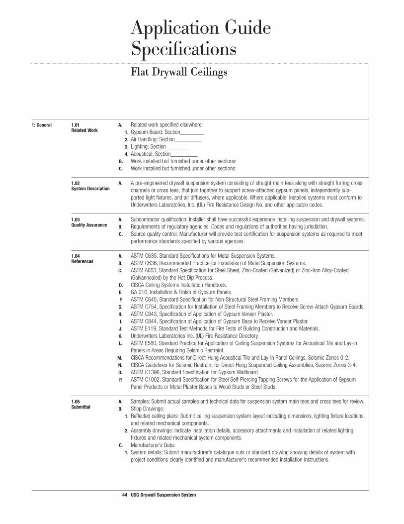
�:General �.0� A. Relatedworkspecifiedelsewhere: RelatedWork �. GypsumBoard:Section________
2. AirHandling:Section_________3. Lighting:Section_______4. Acoustical:Section_________
B. Workinstalledbutfurnishedunderothersections:C. Workinstalledbutfurnishedunderothersections:
�.02 A. Apre-engineereddrywallsuspensionsystemconsistingofstraightmainteesalongwithstraightfurringcrossSystemDescription channelsorcrosstees,thatjointogethertosupportscrew-attachedgypsumpanels,independentlysup-
portedlightfixtures,andairdiffusers,whereapplicable.Whereapplicable,installedsystemsmustconformtoUnderwritersLaboratories,Inc.(UL)FireResistanceDesignNo.andotherapplicablecodes.
�.03 A. Subcontractorqualification:Installershallhavesuccessfulexperienceinstallingsuspensionanddrywallsystems.QualityAssurance B. Requirementsofregulatoryagencies:Codesandregulationsofauthoritieshavingjurisdiction.
C. Sourcequalitycontrol:Manufacturerwillprovidetestcertificationforsuspensionsystemsasrequiredtomeetperformancestandardsspecifiedbyvariousagencies.
�.04 A. ASTMC635,StandardSpecificationsforMetalSuspensionSystems.References B. ASTMC636,RecommendedPracticeforInstallationofMetalSuspensionSystems. C. ASTMA653,StandardSpecificationforSteelSheet,Zinc-Coated(Galvanized)orZinc-IronAlloy-Coated
(Galvannealed)bytheHot-DipProcess.D. CISCACeilingSystemsInstallationHandbook.E. GA216,Installation&FinishofGypsumPanels.
F. ASTMC645,StandardSpecificationforNon-StructuralSteelFramingMembers. G. ASTMC754,SpecificationforInstallationofSteelFramingMemberstoReceiveScrew-AttachGypsumBoards. H. ASTMC843,SpecificationofApplicationofGypsumVeneerPlaster. I. ASTMC844,SpecificationofApplicationofGypsumBasetoReceiveVeneerPlaster. J. ASTME119,StandardTestMethodsforFireTestsofBuildingConstructionandMaterials. K. UnderwritersLaboratoriesInc.(UL)FireResistanceDirectory. L. ASTME580,StandardPracticeforApplicationofCeilingSuspensionSystemsforAcousticalTileandLay-in
PanelsinAreasRequiringSeismicRestraint. M. CISCARecommendationsforDirect-HungAcousticalTileandLay-InPanelCeilings,SeismicZones0-2. N. CISCAGuidelinesforSeismicRestraintforDirect-HungSuspendedCeilingAssemblies,SeismicZones3-4. O. ASTMC1396,StandardSpecificationforGypsumWallboard. P. ASTMC1002,StandardSpecificationforSteelSelf-PiercingTappingScrewsfortheApplicationofGypsum
PanelProductsorMetalPlasterBasestoWoodStudsorSteelStuds.
�.05 A. Samples:Submitactualsamplesandtechnicaldataforsuspensionsystemmainteesandcrossteesforreview.Submittal B. ShopDrawings:
�. Reflectedceilingplans:Submitceilingsuspensionsystemlayoutindicatingdimensions,lightingfixturelocations,andrelatedmechanicalcomponents.
2. Assemblydrawings:Indicateinstallationdetails,accessoryattachmentsandinstallationofrelatedlightingfixturesandrelatedmechanicalsystemcomponents.
C. Manufacturer’sData:�. Systemdetails:Submitmanufacturer’scataloguecutsorstandarddrawingshowingdetailsofsystemwith
projectconditionsclearlyidentifiedandmanufacturer’srecommendedinstallationinstructions.
Application Guide SpecificationsFlat Drywall CeilingsFlat Drywall Ceilings

45 USGDrywallSuspensionSystem
�.06 A. Deliveryofmaterials:Delivermaterialsinoriginal,unopenedpackagesclearlylabeledwithamanufacturer’sDelivery,Storage name,itemdescription,partnumber,typeandclassasapplicable.andHandling
B. Inspection:Promptlyinspectdeliveredmaterials,filefreightclaimsfordamageduringshipment,andorderreplacementofmaterialsasrequired.Anydamagedmaterialsshallbepromptlyremovedfromthejobsite.
C. Storage:Storeinamannerthatwillpreventwarpage,waterdamage,ordamageofanykind.Preventinterfer-enceto/byothertradesandanyotheradversejobconditionsduetostoragelocationsormethods.Warning:StoreallSheetrockBrandGypsumPanelsflat.Panelsareheavyandcanfallover,causingseriousinjuryordeath.Donotmoveunlessauthorized.
D. Handling:Handleinsuchamannertoinsureagainstracking,distortionorphysicaldamageofanykind.
�.07 A. Existingconditions:(includespecificalterationworkrequirementsfortheproject). Project B. Environmentalrequirements:
Conditions �. BuildingConditions:Buildingshallbeenclosedwithallwindowsandexteriordoorsinplaceandglazed,and
roofwatertightbeforeinstallationofsuspensionsystem.2. Interiortemperature/humidityinbuilding:Climacticconditionsinareastoreceivedrywallsuspensionsystems
shallrangefrom60°F(16°C)to104°F(40°C)andrelativehumidityofnotmorethan90%shallbemain-tainedbeforeinstallationofcomponents.
3. Incoldweatherduringgypsumpanelinstallationandjointfinishingandveneerplasterapplication,temperatureswithinthebuildingshallbemaintainedintherangeof55-70°F(13-21°C).Heatandventilationshouldbeevenlyprovidedtofacilitatecuringanddrying.
C. Coordinationwithotherwork:�. General:Coordinatewithotherworksupportedbyorpenetratingthroughtheceiling,includingmechanicaland
electricalworkandpartitionsystems.2. Mechanicalwork:Ductworkabovesystemshallbecomplete,andpermanentHVACsystemsoperating.3. ElectricalWork:Installationofconduitabovesuspensionsystemshallbecompletebeforeinstallationofsuspen-
sionsystem.D. Protection:
�. Personnel:Followgoodsafetyandindustrialhygienepracticesduringhandlingandinstallingofallproductsandsystems,withpersonneltotakenecessaryprecautionsandwearappropriatepersonalprotectiveequipmentasneeded.Readmaterialsafetydatasheetsandrelatedliteratureforimportantinformationonproductsbeforeinstallation.Contractortobesolelyresponsibleforallpersonalsafetyissuesduringandsubsequenttoinstallation.Architect,specifier,ownerandmanufacturerwillrelyoncontractor’sperformanceinsuchregard.
2:Products 2.0� A. USGdrywallsuspensionsystem. Manufacturer B. USGSheetrockbrandgypsumproducts,panelsandaccessories(regular,firecoDe, firecoDeC).SeeGypsum
Products: Panels and Accessories(SA927)forspecifications. C. USGSheetrockbrandjointtape,jointcompounds,trim,andaccessories.SeeSheetrock BrandInterior Finishing
Products (J1424)forspecifications. D. USGimperialbrandgypsumbase.SeePlasterSystems(SA920)forspecification.AllmanufacturedbyUSG,
Chicago,ILUSA.ManufacturedinaccordancewithASTMC588,StandardSpecificationforGypsumBaseforVeneerPlasters.
E. USGfiberockbrandaQua-toughinteriorpanels.SeeMoisture-Resistant Assemblies(SA934)forspecifications. F. USGDurockbrandcementboard.SeeMoisture-Resistant Assemblies(SA934)forspecifications.

46 USGDrywallSuspensionSystem
2.02 A. Commercial-quality,cold-rolledsteel,hot-dippedgalvanizedfinish.Materials B. USGFlatDrywallSuspensionsSystems:
�. MainTees:Fire-RatedHeavyDutyclassification,144long,withintegralreversiblesplicewithknurledface.DGLW261-1/2Face,1.617highor
DGL2615/16Face,1-1/2high2. CrossMembers:Fire-Ratedmemberswithknurledface.
CrossTees:DGLW424crosstee1-1/2highx48longwith1-1/2wideface.Teesmusthavequickreleasecrossteeendstoprovidepositivelockingandremovabilitywithouttheneedfortools.orFurringChannel:DGCL-4furringchannel7/8highx48longwith1-1/2face.
3. AccessoryCrossTees:Crossteesmusthaveknurledfaces.Crossteeshavequickreleasecrossteeendstoprovidepositivelockingandremovabilitywithouttheneedfortools.DGL224Fire-Rated 1-1/2highx24longwith15/16faceDGL424Fire-Rated 1-1/2highx48longwith15/16faceDGLW224Fire-Rated 1-1/2highx24longwith1-1/2faceDGLW424Fire-Rated 1-1/2highx48longwith1-1/2face
4. Wallmoldings:Singlewebwithknurledface.DGWM24 1x1-1/2x144longwallmolding.DGCM27 144x1-5/8x1channelmolding.
C. Accessories�. TransitionclipDGTC-902. SpliceclipDGSC-180
3.WallattachmentclipDGWC 4.SpliceplateDGSP 5. DomehubDGHUB 6. compaSSodrywallclipDGC4,DGC6,DGC8
D. USGcompäSSotrim�. 4compäSSotrim:4wideface,9/16horizontallegswithhemsformedforattachmenttothecompäSSo
mountingclip,commercial-qualitycold-rolled24-gaugesteelwithfactoryfinish.2. 6compäSSotrim:6wideface,9/16horizontallegswithhemsformedforattachmenttothecompäSSo
mountingclip,commercial-qualitycold-rolled24-gaugesteelwithfactoryfinish. 3. 8compäSSotrim:8wideface,9/16horizontallegswithhemsformedforattachmenttothecompäSSo
mountingclip,commercial-qualitycold-rolled24-gaugesteelwithfactoryfinish. 4.10compäSSotrim:10wideface,9/16horizontallegswithhemsformedforattachmenttothecompäSSo
mountingclip;commercial-qualitycold-rolled24-gaugesteelwithfactoryfinish. 5. 12compäSSotrim:12wideface,9/16horizontallegswithhemsformedforattachmenttothecompäSSo
mountingclip;commercial-qualitycold-rolled24-gaugesteelwithfactoryfinish.E. Gypsumpanels �. GypsumpanelsmanufacturedinaccordancewithASTMC36. 2. 1/4,3/8,1/2,5/8,and3/4Sheetrockbrandgypsumpanels(Regular,firecoDe, firecoDeC)and1/2
Sheetrock brandinteriorgypsumceilingboard.(seeUSGDrywall–SteelFramedSystemsSpecifications—SA92309250-USG-3).
F. USGSheetrockbranddrywallaccessories;trims,expansionjoints,sealants,jointcompoundmaterials.(seeUSGGypsumPanels&AccessoriesSpecificationsSA92709250.
G. fiberockbrandabuse-resistantpanels,Durockbrandcementboard,andimperialbrandabuse-resistantgypsumbase.
Application Guide SpecificationsFlat Drywall Ceilings

47 USGDrywallSuspensionSystem
2.03 A. CornerReinforcement:Minimum#26gauge,zincalloywithorwithoutpaperflangesorplasticbead.Metal,Paperor B. CasingReinforcement:Minimum#24gauge,zincalloyorplasticwithexpandedflanges.PlasticTrim
C. ControlJoints:Minimum#26gauge,zincalloy.093,extrudedaluminumorplasticwithexpandedflanges.
2.04 A. ConventionalGypsumPanelfasteners(ASTMC1002).No.6Type-S,HiLobuglehead,self-drilling,self-tappingFasteners steelscrews.
3:Execution 3.0� A. Examineareastoreceivematerialsforconditionswhichwilladverselyaffectinstallation.Providewrittenreport Inspection ofunacceptablesurface. B. Donotstartworkuntilunsatisfactoryconditionsarecorrected. C. Worktobeconcealed:Verifyworkaboveceilingsuspensionsystemiscompleteandinstalledinmannerwhich
willnotaffectlayoutandinstallationofsuspensionsystemcomponents. D. Beginningofinstallationshallsignifyacceptanceofconditionsinareastoreceiveceilingsuspensionsystem. F. Fire-ratingrequirements:Constructionabovefire-ratedassemblyshallmeetrequirementsasapplicabletopro-
videfire-resistanceratingspecifiedinPart2-Products.
3.02 A. Fielddimensionsmustbeverifiedpriortoinstallation. Preparation
3.03 A. Standardreference:InstallinaccordancewithASTMC636,CISCAinstallationstandards,andotherapplicableInstallation codereferences.
B. Manufacturer’sreference:Installinaccordancewithmanufacturer’scurrentprintedrecommendations.C. Drawingreference:Installinaccordancewithapprovedshopdrawingsandlocateceilinginaccordancewith
mainteedimensionsrelativetoelevations.D. Componentandhangerwireinstallation:
FlatCeilings:Mainteesshallbespacedamaximumof48oncenterandsupportedbyhangerwiresspacedamaximum48oncenterandasspecifiedbyULFireResistanceDirectoryattachinghangerwiresdirectlytostructureabove.Crossteesshallbespacedpermanufacturers’recommendationsandasspecifiedbyULFireResistanceDirectory.Transitions:ChangesinElevationinSoffitandFasciaCeilingApplications.Whenconstructingsteppedsoffits,bracingofthedrywallsuspensionsystemand/oradditionalhangerwiresmaybenecessarytoensurestabilityandstructuralperformanceduringandafterdrywallattachment.Themaximumverticalsoffitheightis48.(Maximumunsupporteddrywallareashallnotexceed48x24).Intermediatecrossteesarenotnecessarywhensoffitdimensionsdonotexceed24.Crossteespacinginhorizontalsoffitplaneisnottoexceed24.Intermediatecrossteesmaybenecessarytomaintainvisuallyacceptabledrywallplanesanddrywallcorners.
Generalhangerwirenotes:Hangerwiresarerequiredwithin12onbothsidesofapivotedspliceclip. Atleast1hangerwireisrequiredwithin12ofatransitionclip. Limitations:Donotsupportwiresfrommechanicaland/orelectricalequipmentoccurringaboveceiling. E. Accessories:Installaccessoriesasapplicabletomeetprojectrequirements.

48 USGDrywallSuspensionSystem
Application Guide Specifications
3.04 A. Applygypsumpanelsfirsttoceilingandthentowalls.PositionallendsandedgesofgypsumpanelsatframingGypsumPanel members.Extendceilingboardtocornersandmakefirmcontactwiththewallangle,channelortopplate.ToInstallation
minimizeendjoints,usepanelsofmaximumpracticallengths.Fitendsandedgesclosely,butnotforcedtogether. B. Cutends,edges,scribeormakecutoutswithinthefieldofpanelsinaworkmanlikemanner.Cutgypsumboard
tosizeusingaknifeandstraightedge. C. Attachgypsumpanelstothesuspensionsystemmainrunners,crossteesandcrosschannelswithconventional
gypsumpanelfasteners(No.6TypeSHiLobuglehead,self-drilling,self-tappingsteelscrews)spaced8o.c.atperipheryofgypsumpanelsandlocated3/8infrompaneledgesandspaced12o.c.inthefield.Drivefastenersinfieldofpanelsfirst,workingtowardendsandedges.Holdpanelsinfirmcontactwithframingwhiledrivingfasteners.Drivefastenerheadsslightlybelowsurfaceofgypsumpanelswithoutbreakingfacepaper.(SeeGypsumPanelandAccessoriesSpecificationSA92709250).Installtrimatallinternalandexternalanglesformedbytheintersectionofpanelsurfacesorotherdissimilarmaterials.Applycornerreinforcementtoallverticalorhorizontalexternalcornersinaccordancewithmanufacturer’sdirections.
Ceilingsnote:SeeDrywall–SteelFramedSystemsSpecificationsSA92309250USG-3. Spacingofdrywallgridisdesignedtosupportonlythedeadload.Heavyconcentratedloadsshouldbeinde-
pendentlysupported.Lightingfixturesortroffers,airventsandotherequipmentshouldbeseparatelysupportedfromthestructure;gypsumpanelswillnotsupporttheseitems.
Topreventobjectionablesaginnewgypsumpanelceilings,theweightofoverlaidunsupportedinsulationshouldnotexceed1.3psffor1/2thickgypsumpanelswithspacingof24o.c.;2.2psffor1/2thickgypsumpanels16o.c.framingand1/2Sheetrockbrandinteriorgypsumceilingpanelson24o.c.framingand5/8panels24o.c.;3/8thickgypsumpanelsmustnotbeoverlaidwithunsupportedinsulation.Avaporretardershouldbeinstalledinexteriorceilings,andplenumoratticspacesshouldbeproperlyvented.
Duringperiodsofcoldordampweatherwhenapolyethylenevaporretarderisinstalledonceilingsbehindthegypsumpanelsitisimportanttoinstalltheceilinginsulationbeforeorimmediatelyafterinstallingthegypsumpanels.Failuretofollowthisproceduremayresultinmoisturecondensationinthebackofthegypsumpanelscausingsag.
E. Spray-TexturedCeilings:Wherewater-basedtexturingmaterialsoranyslow-dryingsurfacetreatmentareusedoversingle-layerpanels,maximumframespacingis16o.c.for1/2panelsappliedperpendiculartoframing.
3.05 A. ProvideaseparationinthesuspensionsystematexpansionjointsasshownonthedrawingsandcarrytheExpansionJoints jointthroughthegypsumpanels.Expansionjointsareinstalledtoseparatethesuspensionsystemandallow
formovementinlargeceilingareas.
3.06 A. ProvidecontroljointNo..093whichhasa3/32groundfordrywallandveneerplaster.Ceilingareasshouldnotexceed2,500sq.ft.withperimeterreliefor900sq.ft.withoutperimeterrelief.
Flat Drywall Ceilings
49 USGDrywallSuspensionSystem
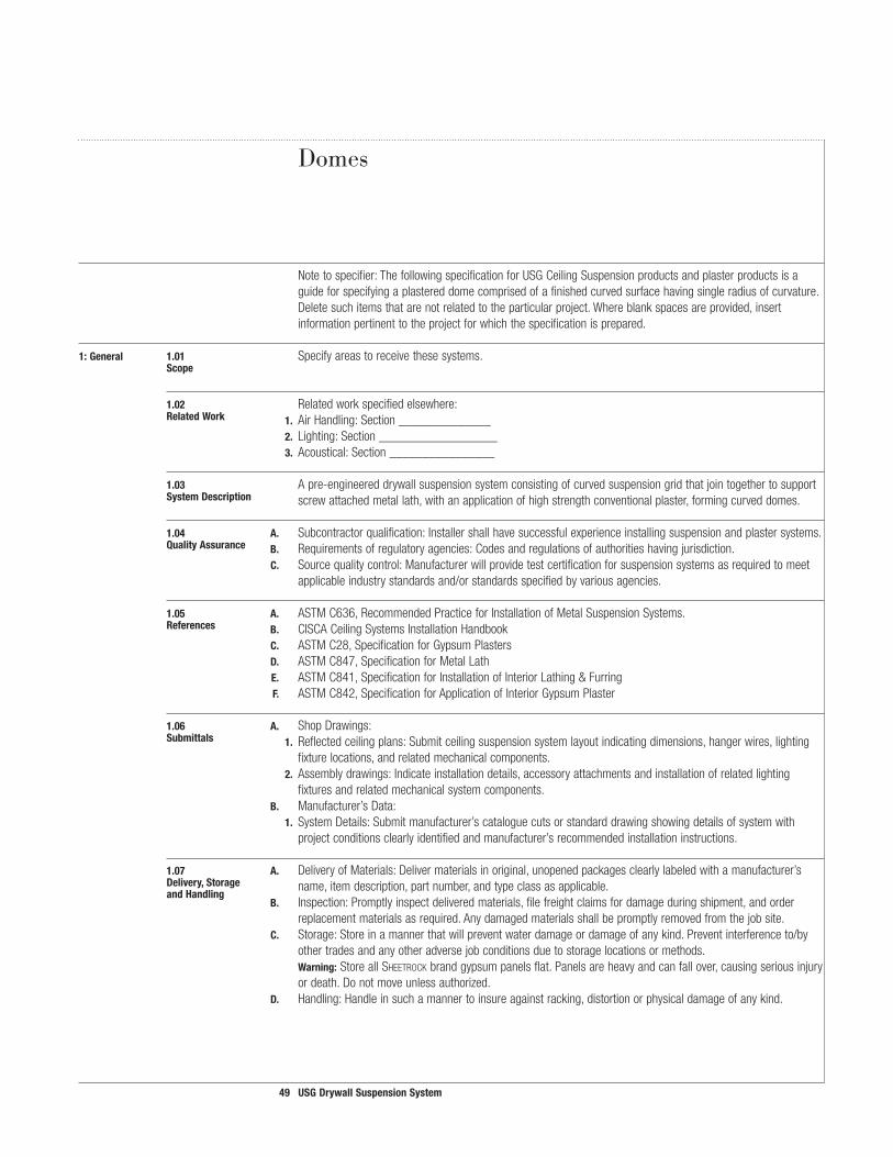
Notetospecifier:ThefollowingspecificationforUSGCeilingSuspensionproductsandplasterproductsisaguideforspecifyingaplastereddomecomprisedofafinishedcurvedsurfacehavingsingleradiusofcurvature.Deletesuchitemsthatarenotrelatedtotheparticularproject.Whereblankspacesareprovided,insertinformationpertinenttotheprojectforwhichthespecificationisprepared.
�:General �.0� Specifyareastoreceivethesesystems. Scope
�.02 Relatedworkspecifiedelsewhere: RelatedWork �. AirHandling:Section______________ 2. Lighting:Section__________________ 3. Acoustical:Section________________
�.03 Apre-engineereddrywallsuspensionsystemconsistingofcurvedsuspensiongridthatjointogethertosupport SystemDescription screwattachedmetallath,withanapplicationofhighstrengthconventionalplaster,formingcurveddomes.
�.04 A. Subcontractorqualification:Installershallhavesuccessfulexperienceinstallingsuspensionandplastersystems. QualityAssurance B. Requirementsofregulatoryagencies:Codesandregulationsofauthoritieshavingjurisdiction. C. Sourcequalitycontrol:Manufacturerwillprovidetestcertificationforsuspensionsystemsasrequiredtomeet
applicableindustrystandardsand/orstandardsspecifiedbyvariousagencies.
�.05 A. ASTMC636,RecommendedPracticeforInstallationofMetalSuspensionSystems. References B. CISCACeilingSystemsInstallationHandbook C. ASTMC28,SpecificationforGypsumPlasters D. ASTMC847,SpecificationforMetalLath E. ASTMC841,SpecificationforInstallationofInteriorLathing&Furring F. ASTMC842,SpecificationforApplicationofInteriorGypsumPlaster
�.06 A. ShopDrawings: Submittals �. Reflectedceilingplans:Submitceilingsuspensionsystemlayoutindicatingdimensions,hangerwires,lighting
fixturelocations,andrelatedmechanicalcomponents. 2. Assemblydrawings:Indicateinstallationdetails,accessoryattachmentsandinstallationofrelatedlighting
fixturesandrelatedmechanicalsystemcomponents. B. Manufacturer’sData: �. SystemDetails:Submitmanufacturer’scataloguecutsorstandarddrawingshowingdetailsofsystemwith
projectconditionsclearlyidentifiedandmanufacturer’srecommendedinstallationinstructions.
�.07 A. DeliveryofMaterials:Delivermaterialsinoriginal,unopenedpackagesclearlylabeledwithamanufacturer’s Delivery,Storage name,itemdescription,partnumber,andtypeclassasapplicable.
andHandling B. Inspection:Promptlyinspectdeliveredmaterials,filefreightclaimsfordamageduringshipment,andorder
replacementmaterialsasrequired.Anydamagedmaterialsshallbepromptlyremovedfromthejobsite. C. Storage:Storeinamannerthatwillpreventwaterdamageordamageofanykind.Preventinterferenceto/by
othertradesandanyotheradversejobconditionsduetostoragelocationsormethods.Warning:StoreallSheetrockbrandgypsumpanelsflat.Panelsareheavyandcanfallover,causingseriousinjuryordeath.Donotmoveunlessauthorized.
D. Handling:Handleinsuchamannertoinsureagainstracking,distortionorphysicaldamageofanykind.
Domes

50 USGDrywallSuspensionSystem
Application Guide Specifications
�.08 A. EnvironmentalRequirements: Project �. BuildingConditions:Buildingshallbeenclosedwithallwidowsandexteriordoorsinplaceandglazedand
Conditions roofwatertightbeforeinstallationofsuspensionsystemandplaster.
2. Temperatureswithinthebuildingshallbemaintainedintherangeof55-70°F(13-21°C).Heatandventilationshallbeevenlyprovidedtofacilitatedrying.
B. CoordinationwithOtherWork: �. General:Coordinatewithotherworksupportedbyorpenetratingthroughthedome,includingmechanical
andelectricalwork. 2. Mechanicalwork:DuctworkabovesystemshallbecompleteandpermanentHVACsystemsoperating. 3. Electricalwork:Installationofconduitabovesuspensionsystemshallbecompletebeforeinstallationof
suspensionsystem C. Protection:Followgoodsafetyandindustrialhygienepracticesduringhandlingandinstallingofallproducts
andsystems,withpersonneltotakenecessaryprecautionsandwearappropriatepersonalprotectiveequip-mentasneeded.ReadMaterialSafetyDataSheetsandrelatedliteratureforimportantinformationonproductsbeforeinstallation.Contractortobesolelyresponsibleforallpersonalsafetyissuesduringandsubsequenttoinstallation;architect,specifier,ownerandmanufacturerwillrelyoncontractor’sperformanceinsuchregard.
2:Products 2.0� A. USGdrywallgridsuspensionsystem Materials B. Structo-baSe®gypsumplaster C. Structo-gauge®gaugingplaster D. reD top®finishplaster E. DiamonD®interiorfinishplaster AllmanufacturedbyUSG,Chicago,IL,USA,incompliancewithASTMStandards. F. Factory-curved,1-1/2x1-1/2USGdrywallgridwithknurledface—commercial-quality,cold-rolledsteel,
hot-dippedgalvanizedfinish.Crossteeholesspaced8o.c. Manufacturer’sdesignationDGW__VT__ G. Wire �. Hangerwire(12ga.)(8ga.),galvanized 2. Tiewire–18gauge,galvanized H. Metallath:3.4#/S.Y.self-furringdiamondmeshlath,galvanized I. Screws–Self-tappingtruss-headlathingscrews. J. Gypsumplaster:Structo-baSegypsumplaster K. Sand:ASTMC35 L. Water:Cleanandpotable M. Finishplaster:Tobedetermined N. Domehubandconnectingclips O. Casingandcornerbeadsasrequired P. Accessoriesasapplicabletoprojectrequirements
Domes

5� USGDrywallSuspensionSystem
3:Execution 3.0� A. Examineareastoreceivematerialsforconditionswhichwilladverselyaffectinstallation.Providewrittenreport Inspection ofunacceptablesurface. B. Donotstartworkuntilunsatisfactoryconditionsarecorrected. C. Worktobeconcealed:Verifyworkaboveceilingsuspensionsystemiscompleteandinstalledinmannerwhich
willnotaffectlayoutandinstallationofsuspensionsystemcomponents. D. Beginningofinstallationshallsignifyacceptanceofconditionsinareastoreceiveceilingsuspensionsystem. E. Fielddimensionsmustbeverifiedpriortoinstallation.
3.02 A. Standardreference:InstallgridmembersinaccordancewithASTMC636. Installation B. CISCAinstallationstandardsorotherapplicablecodeormanufacturers’references. C. Manufacturer’sreference:Installinaccordancewithmanufacturer’scurrentprintedrecommendations. D. Drawingreference:Installinaccordancewithapprovedshopdrawingsandlocateceilinginaccordancewith
mainteedimensionsrelativetoelevations. E. HangerWireInstallation:Hangerwiresarerequiredalongtheradialsuspensionmembers(spokes)spacedno
morethan32asmeasuredalongthearcofthemember.Additionalhangerwirestoupperstructuralelements.Donotsupporthangersfrommechanicaland/orelectricalequipment.
F. Spaceradialspokememberssoasnottoexceed48spacingatanypoint. G. Spacecrossteememberssothemaximumspanofmetallathis(16)(12). H. Securemetallathtoteememberswithscrewsspaced6o.c.max.,appliedatlathribs.Lapmetallathends
andedgesandsecurewith18gaugetiewirespaced6o.c. I. MixStructo-baSegypsumplasterwithsandinproportionsof2cu.ft.ofsandper100lbs.ofplasterfor
scratchandbrowncoats.Applyplastertometallathtoathicknessof5/8(min.)Measuredfromthefaceofthelath.
J. Selectaplastermixforthefinishcoattoprovideasmoothtrowelorsandfloat(Textured)finish.(ReferenceSA920)
K. Usetemplate(s)toinsureuniformandevencurvatureofthefinishedsurface

52 USGDrywallSuspensionSystem
Application Guide Specifications
Notetospecifier:ThefollowingspecificationfortheUSGDrywallSuspensionSystemisaguideforspecifyingcurveddrywallceilings.Deletesuchitemsthatarenotrelatedtotheparticularproject.Whereblankspacesoccur,provideinformationtotheparticularprojectforwhichthespecificationisprepared.
�:General �.0� A. Relatedworkspecifiedelsewhere: RelatedWork �. GypsumBoard:Section________
2. AirHandling:Section_________3. Lighting:Section_______4. Acoustical:Section_________
B. Workinstalledbutfurnishedunderothersections:C. Workinstalledbutfurnishedunderothersections:
�.02 A. Apre-engineereddrywallsuspensionsystemconsistingofstraightandcurvedmainteesalongwithstraightSystemDescription furringcrosschannelsorcrosstees,thatjointogethertosupportscrewattachedgypsumpanelsandindepen-
dentlysupportedlightfixtures,andairdiffusers,whereapplicable.Whereapplicable,installedsystemsmustconformtoUnderwritersLaboratories,Inc.(UL)FireResistanceDesignNo.andotherapplicablecodes.
�.03 A. Subcontractorqualification:Installershallhavesuccessfulexperienceinstallingsuspensionanddrywallsystems.QualityAssurance B. Requirementsofregulatoryagencies:Codesandregulationsofauthoritieshavingjurisdiction.
C. Sourcequalitycontrol:Manufacturerwillprovidetestcertificationforsuspensionsystemsasrequiredtomeetperformancestandardsspecifiedbyvariousagencies.
�.04 A. ASTMC635,StandardSpecificationsforMetalSuspensionSystems.References B. ASTMC636,RecommendedPracticeforInstallationofMetalSuspensionSystems.
C. CISCACeilingSystemsInstallationHandbook. D. GA216,Installation&FinishofGypsumPanels. E. ASTMC645,StandardSpecificationforNon-StructuralSteelFramingMembers. F. ASTMC754,SpecificationforInstallationofSteelFramingMemberstoReceiveScrew-AttachGypsumBoards. G. ASTMC843,SpecificationofApplicationofGypsumVeneerPlaster. H. ASTMC844,SpecificationofApplicationofGypsumBasetoReceiveVeneerPlaster. I. ASTME119,StandardTestMethodsforFireTestsofBuildingConstructionandMaterials. J. UnderwritersLaboratoriesInc.(UL)FireResistanceDirectory.
�.05 A. Samples:Submitactualsamplesandtechnicaldataforsuspensionsystemmainteesandcrossteesforreview.Submittal B. Shopdrawings:
�. Reflectedceilingplans:Submitceilingsuspensionsystemlayoutindicatingdimensions,lightingfixturelocations,andrelatedmechanicalcomponents.
2. Assemblydrawings:Indicateinstallationdetails,accessoryattachmentsandinstallationofrelatedlightingfixturesandrelatedmechanicalsystemcomponents.
C. Manufacturer’sData: �. Systemdetails:Submitmanufacturer’scataloguecutsorstandarddrawingshowingdetailsofsystemwithproject
conditionsclearlyidentifiedandmanufacturer’srecommendedinstallationinstructions.
Curved Drywall Ceilings
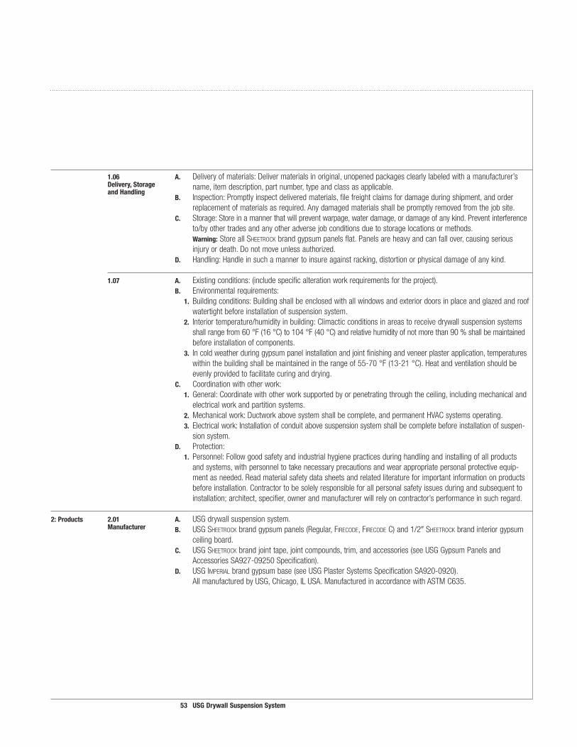
53 USGDrywallSuspensionSystem
�.06 A. Deliveryofmaterials:Delivermaterialsinoriginal,unopenedpackagesclearlylabeledwithamanufacturer’sDelivery,Storage name,itemdescription,partnumber,typeandclassasapplicable.andHandling
B. Inspection:Promptlyinspectdeliveredmaterials,filefreightclaimsfordamageduringshipment,andorderreplacementofmaterialsasrequired.Anydamagedmaterialsshallbepromptlyremovedfromthejobsite.
C. Storage:Storeinamannerthatwillpreventwarpage,waterdamage,ordamageofanykind.Preventinterferenceto/byothertradesandanyotheradversejobconditionsduetostoragelocationsormethods.Warning:StoreallSheetrockbrandgypsumpanelsflat.Panelsareheavyandcanfallover,causingseriousinjuryordeath.Donotmoveunlessauthorized.
D. Handling:Handleinsuchamannertoinsureagainstracking,distortionorphysicaldamageofanykind.
�.07 A. Existingconditions:(includespecificalterationworkrequirementsfortheproject). B. Environmentalrequirements: �. Buildingconditions:Buildingshallbeenclosedwithallwindowsandexteriordoorsinplaceandglazedandroof
watertightbeforeinstallationofsuspensionsystem. 2. Interiortemperature/humidityinbuilding:Climacticconditionsinareastoreceivedrywallsuspensionsystems
shallrangefrom60°F(16°C)to104°F(40°C)andrelativehumidityofnotmorethan90%shallbemaintainedbeforeinstallationofcomponents.
3. Incoldweatherduringgypsumpanelinstallationandjointfinishingandveneerplasterapplication,temperatureswithinthebuildingshallbemaintainedintherangeof55-70°F(13-21°C).Heatandventilationshouldbeevenlyprovidedtofacilitatecuringanddrying.
C. Coordinationwithotherwork: �. General:Coordinatewithotherworksupportedbyorpenetratingthroughtheceiling,includingmechanicaland
electricalworkandpartitionsystems. 2. Mechanicalwork:Ductworkabovesystemshallbecomplete,andpermanentHVACsystemsoperating. 3. Electricalwork:Installationofconduitabovesuspensionsystemshallbecompletebeforeinstallationofsuspen-
sionsystem. D. Protection: �. Personnel:Followgoodsafetyandindustrialhygienepracticesduringhandlingandinstallingofallproducts
andsystems,withpersonneltotakenecessaryprecautionsandwearappropriatepersonalprotectiveequip-mentasneeded.Readmaterialsafetydatasheetsandrelatedliteratureforimportantinformationonproductsbeforeinstallation.Contractortobesolelyresponsibleforallpersonalsafetyissuesduringandsubsequenttoinstallation;architect,specifier,ownerandmanufacturerwillrelyoncontractor’sperformanceinsuchregard.
2:Products 2.0� A. USGdrywallsuspensionsystem. Manufacturer B. USGSheetrockbrandgypsumpanels(Regular,firecoDe, firecoDeC)and1/2Sheetrockbrandinteriorgypsum
ceilingboard. C. USGSheetrockbrandjointtape,jointcompounds,trim,andaccessories(seeUSGGypsumPanelsand
AccessoriesSA927-09250Specification). D. USGimperialbrandgypsumbase(seeUSGPlasterSystemsSpecificationSA920-0920). AllmanufacturedbyUSG,Chicago,ILUSA.ManufacturedinaccordancewithASTMC635.

54 USGDrywallSuspensionSystem
2.02 A. Commercial-quality,cold-rolledsteel,hot-dippedgalvanizedfinish.Materials B. USGflatdrywallsuspensionsystems:
�. Maintees:Fire-RatedHeavyDutyclassification1-1/2highx144long,integralreversiblesplicewithknurledface.DGLW261-1/2FaceDGL-2615/16Face
or DGL2615/16Face 2. Crossmembers:Fire-Ratedmemberswithknurledface. CrossTees:DGLW-424crosstee1-1/2highx48longwith1-1/2wideface.Teesmusthavequickrelease
crossteeendstoprovidepositivelockingandremovabilitywithouttheneedfortools. 3. Accessorycrosstees:Crossteesmusthaveknurledfaces.Crossteeshavequickreleasecrossteeendsto
providepositivelockingandremovabilitywithouttheneedfortools. DGL224Fire-Rated 1-1/2highx24longwith15/16face DGL424Fire-Rated 1-1/2highx48longwith15/16face DGLW224Fire-Rated 1-1/2highx24longwith1-1/2face DGLW424Fire-Rated 1-1/2highx48longwith1-1/2face 4. Wallmoldings:Knurledface. DGCM27 144x1-5/8x1channelmolding. DGWM24 1-1/2x1x144 C. uSgcurveddrywallsuspensionsystems: �. Valleytees(faceofgridconvex):1-1/2highx1-1/2knurledfacewithpartiallycorrugatedbulbandcross-tee
holesat8o.c.Madeofhot-dippedgalvanizedsteel. 2. Vaulttees(faceofgridconcave):1-1/2highx1-1/2knurledfacewithcross-teeholesat8o.c.Madeofhot-
dippedgalvanizedsteel. D. Accessories �. TransitionclipDGTC-90 2. SpliceclipDGSC-180 3. WallattachmentclipDGWC 4. Spliceplate 5. HubDGHUB E. Gypsumpanels �. GypsumpanelsmanufacturedinaccordancewithASTMC36. 2. 1/4,3/8,1/2,5/8Sheetrockbrandgypsumpanels(Regular,firecoDe, firecoDeC).(seeUSGDrywall/Steel
FramedSystemsSpecifications—SA92309250-USG-3). F. USGSheetrockbranddrywallaccessories;trims,expansionjoints,sealants,jointcompoundmaterials. (seeUSGGypsumPanels&AccessoriesSpecificationsSA92709250.
2.03 A. Cornerbead:Minimum#26gauge,zincalloywithorwithoutpaperflangesorplasticbead.Metal,Paperor B. Casingbead:Minimum#24gauge,zincalloyorplasticwithexpandedflanges.PlasticTrim
C. Controljoints:Minimum#26gauge,zincalloy,extrudedaluminumorplasticwithexpandedflanges.
2.04 A. Conventionalgypsumpanelfasteners(ASTMC1002).No.6Type-S,HiLobuglehead,self-drilling,self-tappingFasteners steelscrews.
Application Guide SpecificationsCurved Drywall Ceilings

55 USGDrywallSuspensionSystem
3:Execution 3.0� A. Examineareastoreceivematerialsforconditionswhichwilladverselyaffectinstallation.Providewrittenreport Inspection ofunacceptablesurface. B. Donotstartworkuntilunsatisfactoryconditionsarecorrected. C. Worktobeconcealed:Verifyworkaboveceilingsuspensionsystemiscompleteandinstalledinmannerwhich
willnotaffectlayoutandinstallationofsuspensionsystemcomponents. D. Beginningofinstallationshallsignifyacceptanceofconditionsinareastoreceiveceilingsuspensionsystem. F. Fire-ratingrequirements:Constructionabovefire-ratedassemblyshallmeetrequirementsasapplicableto
providefire-resistanceratingspecifiedinPart2-Products.
3.02 A. Fielddimensionsmustbeverifiedpriortoinstallation. Preparation
3.03 A. Standardreference:InstallinaccordancewithASTMC636,CISCAinstallationstandards,andotherapplicablecode Installation references.
B. Manufacturer’sreference:Installinaccordancewithmanufacturer’scurrentprintedrecommendations.C. Drawingreference:Installinaccordancewithapprovedshopdrawingsandlocateceilinginaccordancewith
mainteedimensionsrelativetoelevations.D. Componentandhangerwireinstallation:
Flatceilings:Mainteesshallbespacedamaximumof48oncenterandsupportedbyhangerwiresspacedamaximum48oncenterandasspecifiedbyULFireResistanceDirectoryattachinghangerwiresdirectlytostructureabove.Crossteesshallbespacedpermanufacturers’recommendationsandasspecifiedbyULFireResistanceDirectory.Curvedceilings:ValleyandVaultmainteesshallbespacedamaximum48.Hangerwiresshallbespacedamaximum48forVaultsmaintees.Hangerwiresshallbespacedamaximum24forValleymaintees.Crossteesshallbespacedaspermanufacturers’recommendations.Additionalhangerwiresmaybenecessarytostabilizeanycurvedceilingduringandafterdrywallattachment.Transitions:changesinelevationinsoffitandfasciaceilingapplications.Whenconstructingsteppedsoffits,bracingofthedrywallsuspensionsystemand/oradditionalhangerwiresmaybenecessarytoensurestabilityandstructuralperformanceduringandafterdrywallattachment.Themaximumverticalsoffitheightis48.(Maximumunsupporteddrywallareashallnotexceed48x24).Intermediatecrossteesarenotnecessarywhenbulkheaddimensionsdonotexceed24.Crossteespacinginhorizontalsoffitplaneisnottoexceed24.Intermediatecrossteesmaybenecessarytomaintainvisuallyacceptabledrywallplanesanddrywallcorners.
E. uSgsuspensionsystemwhenusedwithSheetrock brandgypsumpanellifetimelimitedwarranty:Bylifetimewemeantheusefullifeofaceilinguptoamaximumof30years.TheuSgdrywallsuspensionsysteminstalledwithoutSheetrock brandgypsumpanelshasa10-yearwarranty.Generalhangerwirenotes:Hangerwiresarerequiredwithin12onbothsidesofapivotedspliceclip.Atleast1hangerwireisrequiredwithin12ofatransitionclip.Limitations:Donotsupportwiresfrommechanicaland/orelectricalequipmentoccurringaboveceiling.
F. Accessories:Installaccessoriesasapplicabletomeetprojectrequirements.
3.04 A. Applygypsumpanelsfirsttoceilingandthentowalls.PositionallendsandedgesofgypsumpanelsatframingGypsumPanel members.Extendceilingboardtocornersandmakefirmcontactwiththewallangle,channelortopplate.Installation
Tominimizeendjoints,usepanelsofmaximumpracticallengths.Fitendsandedgesclosely,butnotforcedtogether.
B. Cutends,edges,scribeormakecutoutswithinthefieldofpanelsinaworkmanlikemanner.Cutgypsumboardtosizeusingaknifeandstraightedge.

Beautiful Results Every Time

Technical Service
800 USG.4YOUWeb Site
usg.comSamples/Literature
888 874.2450Samples/Literature E-mail
[email protected]/Literature/Fax
888 874.2348Customer Service
800 950.3839
Manufactured by USG Interiors, Inc.550 West Adams StreetChicago, IL 60661
AC3152/rev. 5-07© 2007, USG Interiors, Inc.Printed in U.S.A.
NoticeWe shall not be liable for incidental and consequential damages, directly or indirectly sustained, nor for any loss caused by application of these goods not in accordance with current printed instructions or for other than the intended use. Our liability is expressly limited to replacement of defective goods. Any claim shall be deemed waived unless made in writing to us within thirty (30) days from date it was or reasonably should have been discovered. Safety First!Follow good safety and indus-trial hygiene practices during handling and installation of all products and systems. Take necessary precautions and wear the appropriate personal protective equipment as needed. Read material safety data sheets and related literature on prod-ucts before specification and/ or installation.
Product InformationSee usg.com for the most up-to-date product information.NoteAll products described here may not be available in all geographic markets. Consult your local sales office or representative for information. TrademarksThe following are trademarks of USG Corporation or its subsidiaries: AquA-Tough, CenTriCiTee, Compässo, DiAmonD, Donn, DuroCk, DX, DXL, FiberoCk, FireCoDe, imperiAL, quiCk-reLeAse, reD-Top, sheeTroCk, sTruCTo-bAse, sTruCTo-gAuge, TuFF-hiDe, usg.Patents The following are the patent numbers for the USG Drywall Suspension System and its components: 5,937,605; 6,018,923; 6,047,512; and 6,138,425.


