DST-i Oscilloscope SoftwareInstruction Manual
T02145Z
Product Name: DST-i Oscilloscope Software
Number of License: One
NOTICE TO USER: Please read the following License Agreement carefully. The License Agreement is a contract. This software product of “DST-i Oscilloscope Software”, including any document related thereto, is protected by copyright laws and international treaties. You must agree to all of the terms and conditions of the License Agreement before installing or using wholly or partially the product. If you do not agree to any of the terms and conditions of the License Agreement, do not use this product.
License Agreement
This software product of ” DST-i Oscilloscope Software”, including any document related thereto (the “Software”) is the copyrighted work of DENSO CORPORATION (“DENSO”) and its licensor. Under this Agreement, the Software is licensed to you by DENSO subject to the terms and conditions below, not sold nor assigned to you by DENSO. If you use the Software as a natural person, “you” herein means such natural person, and if you use the Software as an officer, employee, agent or other member (including a partner of a partnership) of any legal entity, “you” herein means such legal entity. This Agreement shall take effect as from the day you agree to all of the terms and conditions of the License Agreement. 1. Limited License DENSO grants you a non-exclusive license to install the Software into one certain DST-i hardware in your possession or under your control (“Hardware”), and to use the Software for the sole purpose of diagnosing the trouble of vehicle electronic control systems (“Purpose”). 2. Restrictions (i) You shall not install the Software for any purpose other than Purpose, and shall not use the Software for any purpose other than Purpose. (ii) You shall not use the Software with any hardware other than Hardware. (iii) You shall not rent, lease, sell, sublicense, assign, or otherwise transfer the Software or this Agreement to any third party; provided, however, that
you may assign all of the Software and this Agreement, not part thereof, to your assignee perpetually subject to agreement of such assignee to all of the terms and conditions of this Agreement.
(iv) You shall not copy, reverse engineering, decompile, disassemble, merge, modify or translate the Software. However, you may make one copy of the Software for the sole purpose to make a backup of the Software.
(v) You shall not remove nor obscure DENSO’s copyrights, trademarks or other proprietary notices or legends from any of the materials of the Software.
(vi) You shall not use the Software and/or technology provided by DENSO, or any other products, software and/or technology manufactured or developed by using them for the purposes of disturbing international peace and security, including (1) the design, development, production, stockpiling or use of weapons of mass destruction such as nuclear, chemical or biological weapons or missiles, (2) the other military activities, or (3) any use supporting these activities.
(vii) You shall not sell, export, dispose of, license, rent, transfer, disclose or otherwise provide the Software to any third party, whether directly or indirectly, with knowledge or reason to know that the third party or any other party will engage in the activities described above.
(viii) You shall not directly or indirectly, export, re-export, transship or otherwise transfer the Software in violation of any applicable export control laws or regulations promulgated and administered by the governments of the countries asserting jurisdiction over the parties or their transactions.
(ix) You shall not illegally download the Software from official Webpage of DENSO. 3. Violation of this Agreement Unauthorized install, copy or use of the Software may result in severe civil and criminal penalties, and will be prosecuted to the maximum extent possible. All your rights granted hereunder shall automatically terminate if you fail to comply with any terms and conditions of this Agreement. You shall destroy or erase all of the Software from all media in your possession or under your control if you fail to comply with any terms and conditions of this Agreement. The termination of this Agreement shall not prejudice any rights and remedies that DENSO may have against you. 4. Disclaimer of Warranty; Limitation of Liability THE SOFTWARE IS PROVIDED “AS IS” WITHOUT ANY KIND OF WARRANTY OF ANY PURPOSE. THE SUPPLY OF THE SOFTWARE OR THE GRANT OF RIGHTS HEREUNDER BY DENSO SHALL NOT IMPLY ANY WARRANTY AGAINST INFRINGEMENT OF INTELLECTUAL PROPERTY RIGHTS HELD BY A THIRD PARTY. DENSO MAKES NO REPRESENTATIONS NOR WARRANTIES OF MERCHANTABILITY OR FITNESS FOR A PARTICULAR PURPOSE. DENSO ASSUMES NO RESPONSIBILITY FOR THE APPLICATION OF, ERRORS NOR OMISSION IN THE SOFTWARE. IN NO EVENT SHALL DENSO BE LIABLE FOR ANY DIRECT, INDIRECT, SPECIAL, INCIDENTAL, CONSEQUENTIAL, PUNITIVE OR OTHER DAMAGES ARISING OUT OF OR RESULTING FROM ANY PART OF THE SOFTWARE, THE INSTALLATION OR COPY OF THE SOFTWARE, THE USE OF THE SOFTWARE, OR INABILITY TO USE THE SOFTWARE. FURTHERMORE, DENSO SHALL NOT BE LIABLE FOR ANY LOSS, DAMAGES OR COSTS ARISING OUT OF LOST PROFITS OR REVENUE, LOSS OF USE OF THE SOFTWARE, LOSS OF DATA OR EQUIPMENT, COST OF RECOVERING THE SOFTWARE, DATA OR EQUIPMENT, THE COSTS OF SUBSTITUTE THE SOFTWARE, MEDIA, DATA OR EQUIPMENT OR OTHER SIMILAR COSTS, AND SHALL BE FULLY INDEMNIFIED FROM ANY CLAIM ASSERTED BY YOU OR ANY THIRD PARTY. 5. Governing Law This Agreement shall be governed as to all matters including validity, construction and performance, by and under the laws of Japan, without reference to its conflicts of law principles. 6. Arbitration Any disputes arising out of this Agreement shall be finally settled by arbitration in accordance with the Rules of Conciliation and Arbitration of the International Chamber of Commerce. The award of arbitration shall be final and binding upon the parties. Arbitration shall be held in Tokyo, Japan.
IMPORTANT
Preface
- i -
Thank you for purchasing "set with an oscilloscope".Before using this product, read these instructions carefully so that you can use it correctly and safely.The DST-i oscilloscope software should be the software for (hereinafter referred to as DST-i) model with an oscilloscope.DST-i model without an oscilloscope and hardware other than DST-i cannot be used.An SD memory card (optional) is required to use the DST-i oscilloscope software.
Preface
Safety Instructions
- ii -
This product is intended for the use by a properly trained automotive technician. The following safety instructions should be adhered to prevent harm to the user and/or the vehicle.Since a variety of work procedures, technologies, tools, parts, etc. as well as technician’s skill are used and involved in the diagnosis and maintenance/service of vehicle, various results are predicted and it is impossible to provide a comprehensive set of advice and safety messages that can cover all cases. Therefore, it is the responsibility for an automotive technician to have an adequate knowledge of the diagnosis system. It is also important to perform work appropriately and to ensure your safety and the safety of those around you, as well as to maintain the safety of the vehicle to be diagnosed and the relevant devices to perform appropriate diagnosis and maintenance. The precondition for use of the DST-i is that a user has sufficient knowledge of vehicle diagnostics and the operation of the DST-i to safely use this product.
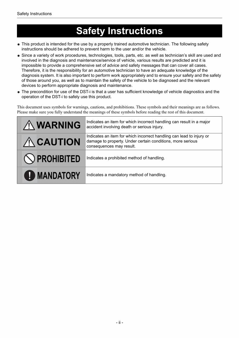
This document uses symbols for warnings, cautions, and prohibitions. These symbols and their meanings are as follows. Please make sure you fully understand the meanings of these symbols before reading the rest of this document.
Safety Instructions
WARNING Indicates an item for which incorrect handling can result in a major accident involving death or serious injury.
CAUTIONIndicates an item for which incorrect handling can lead to injury or damage to property. Under certain conditions, more serious consequences may result.
PROHIBITED Indicates a prohibited method of handling.
MANDATORY Indicates a mandatory method of handling.

Safety Instructions
- iii -
WARNING and CAUTION for handling this product
WARNINGPerform diagnostics and repair work according to the precautions included in "For safe diagnostics".Reference: Page v For safe diagnostics (Safety Instructions)
Refer to safety instructions and diagnosis procedures for the vehicle to be diagnosed and to those provided by the manufacturer of devices before using this product, and adhere to those instructions.Failure to obey the precautions could result in an accident.Do not perform any work while the vehicle is being driven.Doing so could result in an accident.Route the cable so it does not tangle with the technician or the operation control unit.Failure to do so could result in an accident.Always observe the following rules. Failure to do so can result in abnormal heat generation, fire, explosion, or electric shock.- Do not disassemble or alter this product.
- Do not connect this product to anything with voltage exceeding the ratings of this product.
- Do not connect the probe to any parts with voltage exceeding the ratings of this product.
Safety Instructions
- iv -
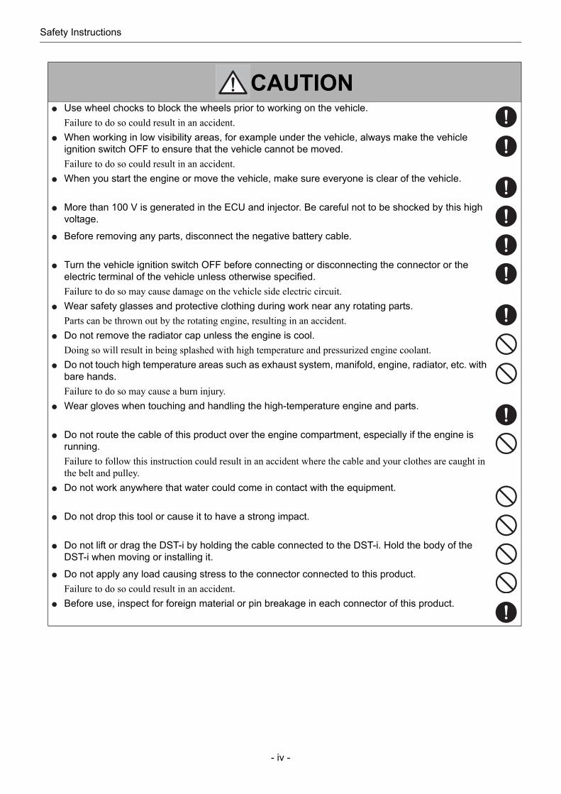
CAUTIONUse wheel chocks to block the wheels prior to working on the vehicle.Failure to do so could result in an accident.When working in low visibility areas, for example under the vehicle, always make the vehicle ignition switch OFF to ensure that the vehicle cannot be moved.Failure to do so could result in an accident.When you start the engine or move the vehicle, make sure everyone is clear of the vehicle.
More than 100 V is generated in the ECU and injector. Be careful not to be shocked by this high voltage.
Before removing any parts, disconnect the negative battery cable.
Turn the vehicle ignition switch OFF before connecting or disconnecting the connector or the electric terminal of the vehicle unless otherwise specified.Failure to do so may cause damage on the vehicle side electric circuit.Wear safety glasses and protective clothing during work near any rotating parts.Parts can be thrown out by the rotating engine, resulting in an accident.Do not remove the radiator cap unless the engine is cool.Doing so will result in being splashed with high temperature and pressurized engine coolant.Do not touch high temperature areas such as exhaust system, manifold, engine, radiator, etc. with bare hands.Failure to do so may cause a burn injury.Wear gloves when touching and handling the high-temperature engine and parts.
Do not route the cable of this product over the engine compartment, especially if the engine is running.Failure to follow this instruction could result in an accident where the cable and your clothes are caught in the belt and pulley.Do not work anywhere that water could come in contact with the equipment.
Do not drop this tool or cause it to have a strong impact.
Do not lift or drag the DST-i by holding the cable connected to the DST-i. Hold the body of the DST-i when moving or installing it.
Do not apply any load causing stress to the connector connected to this product.Failure to do so could result in an accident.Before use, inspect for foreign material or pin breakage in each connector of this product.
Safety Instructions
- v -
For safe diagnostics
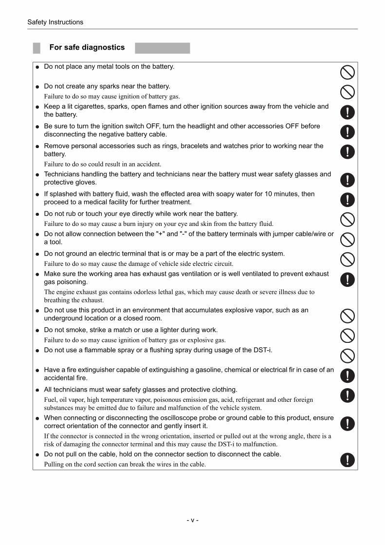
Do not place any metal tools on the battery.
Do not create any sparks near the battery.Failure to do so may cause ignition of battery gas.Keep a lit cigarettes, sparks, open flames and other ignition sources away from the vehicle and the battery.
Be sure to turn the ignition switch OFF, turn the headlight and other accessories OFF before disconnecting the negative battery cable.
Remove personal accessories such as rings, bracelets and watches prior to working near the battery.Failure to do so could result in an accident.Technicians handling the battery and technicians near the battery must wear safety glasses and protective gloves.
If splashed with battery fluid, wash the effected area with soapy water for 10 minutes, then proceed to a medical facility for further treatment.
Do not rub or touch your eye directly while work near the battery.Failure to do so may cause a burn injury on your eye and skin from the battery fluid.Do not allow connection between the "+" and "-" of the battery terminals with jumper cable/wire or a tool.
Do not ground an electric terminal that is or may be a part of the electric system.Failure to do so may cause the damage of vehicle side electric circuit.Make sure the working area has exhaust gas ventilation or is well ventilated to prevent exhaust gas poisoning. The engine exhaust gas contains odorless lethal gas, which may cause death or severe illness due to breathing the exhaust.Do not use this product in an environment that accumulates explosive vapor, such as an underground location or a closed room.
Do not smoke, strike a match or use a lighter during work.Failure to do so may cause ignition of battery gas or explosive gas.Do not use a flammable spray or a flushing spray during usage of the DST-i.
Have a fire extinguisher capable of extinguishing a gasoline, chemical or electrical fir in case of an accidental fire.
All technicians must wear safety glasses and protective clothing.Fuel, oil vapor, high temperature vapor, poisonous emission gas, acid, refrigerant and other foreign substances may be emitted due to failure and malfunction of the vehicle system.When connecting or disconnecting the oscilloscope probe or ground cable to this product, ensure correct orientation of the connector and gently insert it.If the connector is connected in the wrong orientation, inserted or pulled out at the wrong angle, there is a risk of damaging the connector terminal and this may cause the DST-i to malfunction.Do not pull on the cable, hold on the connector section to disconnect the cable.Pulling on the cord section can break the wires in the cable.
Table of contents
- vi -
1 Before Use
1-1 Basic operation .....................................................................................................................................1
1-2 Starting..................................................................................................................................................1
1-3 Ending...................................................................................................................................................7
2 Functions of the DST-i Oscilloscope Software
2-1 Functions ..............................................................................................................................................8Waveform observation functions .............................................................................................................9Long duration data measurement functions ............................................................................................9
3 Operation of the DST-i Oscilloscope Software
3-1 Waveform observation ........................................................................................................................10Screen configuration .............................................................................................................................10Stopping/Starting ................................................................................................................................... 11Time range setting.................................................................................................................................12Setting the channel (waveform display/non-display switching, ground position)...................................13Voltage range setting.............................................................................................................................14Trigger setting .......................................................................................................................................15
3-2 Long duration data measurement .......................................................................................................18Long duration data measurement flow..................................................................................................18Screen configuration .............................................................................................................................18Trigger mode setting .............................................................................................................................19Time range setting.................................................................................................................................20Setting the channel (waveform display/non-display switching, ground position)...................................21Voltage range setting.............................................................................................................................22Setting conditions for recording long duration data measurement ........................................................23Start recording.......................................................................................................................................25
<To record without a start trigger>.....................................................................................................25<To record with a start trigger>..........................................................................................................26
Stop recording .......................................................................................................................................293-3 Saving data .........................................................................................................................................30
3-4 Retrieving data....................................................................................................................................34
3-5 Deleting data.......................................................................................................................................40
3-6 Zero point correction ...........................................................................................................................453-7 Save confirmation message display/non-display setting ....................................................................47
3-8 Termination of the oscilloscope...........................................................................................................49
4 Troubleshooting
4-1 If the screen freezes while using.........................................................................................................504-2 If the system message is displayed ....................................................................................................50
Table of contents

1 Before Use
- 1 -
1 Before Use
The DST-i has six operation buttons.
The function of each button varies depending on the screen.In the lower portion of the screen is a guidance area explaining how to operate the system.Operate using the information displayed in the guidance area.
1. Insert an SD memory card installed with DST-i oscilloscope software to the DST-i unit.
1-1 Basic operation
1-2 Starting
NOTERefer to the "Instruction manual for DST-i hardware with oscilloscope" for the details of the SD memory card.Refer to the following download site for how to install DST-i oscilloscope software.http://www.ds3.denso.co.jp/dst-i/setup/
T02153E
A buttonB buttonGuidance area
Up button
Down button
Right button
Left button
T02585E
Notch to be on
the right side
Confirm the logo mark of
the card.
SDHCSD
Compatible cards
1 Before Use
- 2 -
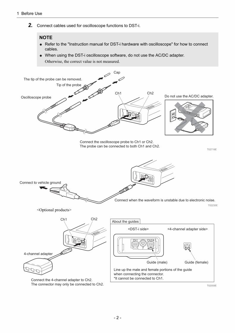
2. Connect cables used for oscilloscope functions to DST-i.
<Optional products>
NOTERefer to the "Instruction manual for DST-i hardware with oscilloscope" for how to connect cables.When using the DST-i oscilloscope software, do not use the AC/DC adapter.Otherwise, the correct value is not measured.
T02719E
The tip of the probe can be removed.
Tip of the probe
Cap
Do not use the AC/DC adapter.Oscilloscope probe
Connect the oscilloscope probe to Ch1 or Ch2.
The probe can be connected to both Ch1 and Ch2.
Ch1 Ch2
T02235E
Connect to vehicle ground
Connect when the waveform is unstable due to electronic noise.
<4-channel adapter side><DST-i side>
T02059E
Guide (female)Guide (male)
About the guides
Line up the male and female portions of the guide
when connecting the connector.
*It cannot be connected to Ch1.
4-channel adapter
Connect the 4-channel adapter to Ch2.
The connector may only be connected to Ch2.
Ch1 Ch2

1 Before Use
- 3 -
3. Connect DST-i and the vehicle side diagnosis connector with a datalink cable.
CAUTIONDo not use a datalink cable other than those intended for DST-i.Check the connector for adhesion of foreign substances or breakage of connector pins before connecting it.When connecting the datalink cable to DST-i and the vehicle side diagnosis connector, pay attention to the connector direction, and connect it straight and gently.Connecting the cable in an incorrect direction or inserting it at an angle may damage the connector terminal and cause a malfunction of the vehicle or DST-i.Do not apply a load to the connector connected to DST-i.Applying a load may damage the connector terminal and cause a malfunction of the vehicle or DST-i.
Tighten with screws.
Notch (Center)
T02005E
Connected to vehicle side diagnosis connector
1 Before Use
- 4 -
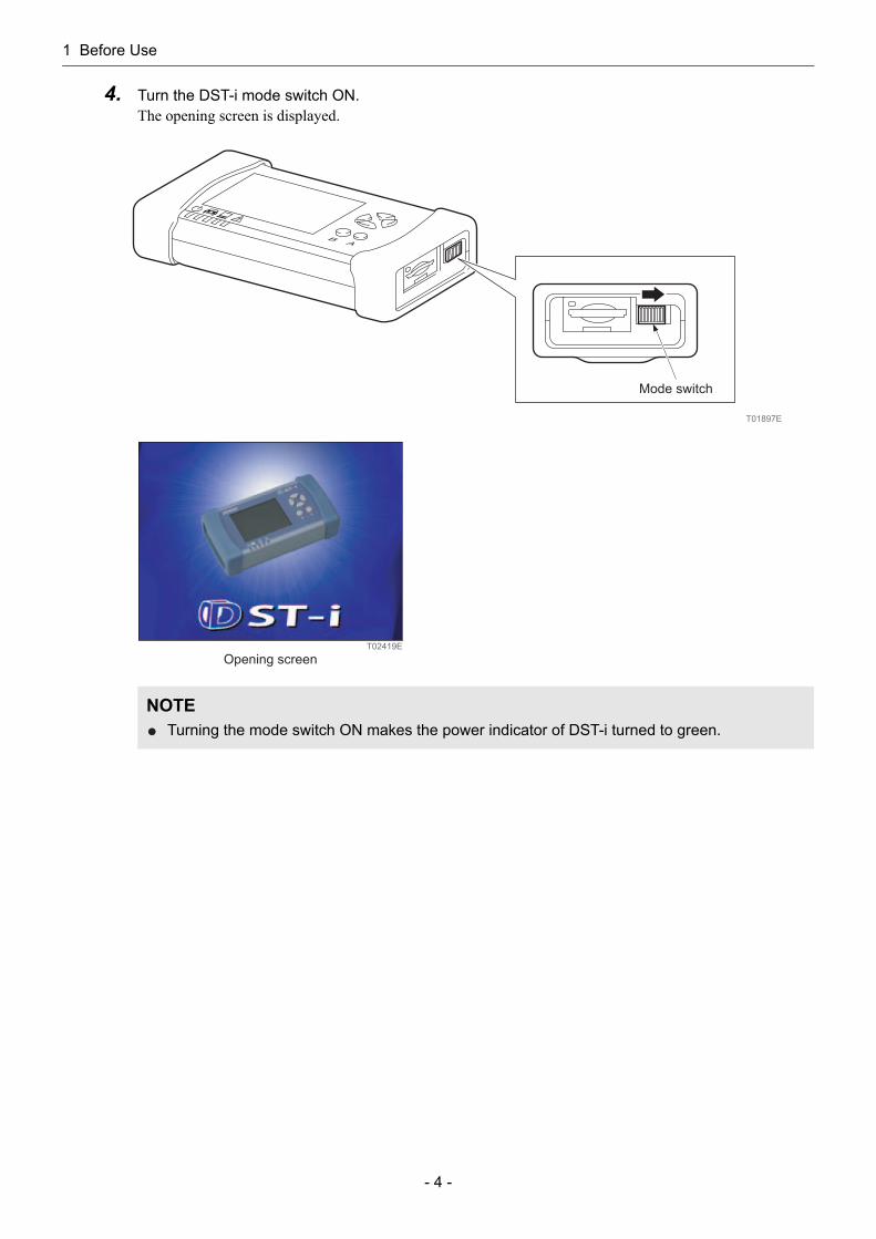
4. Turn the DST-i mode switch ON.The opening screen is displayed.
NOTETurning the mode switch ON makes the power indicator of DST-i turned to green.
T01897E
Mode switch
T02419E
Opening screen

1 Before Use
- 5 -
5. Press any button while the opening screen ON.The main menu screen is displayed.
The following table shows the functions that can be selected in the main menu screen.
6. Select "Oscillo" in the main menu screen, and press the "A" button.The waveform observation screen is displayed.
NOTEThe main menu screen is not displayed when an SD memory card with the oscilloscope software installed is not inserted.When pressing any button shows the error screen, refer to the following page.Reference: Page 6 When the error screen is shown (Chapter 1 Before Use/Starting)
Function Description
Oscillo Observes waveform of signals inputted to each channel on the DST-i screen, when an oscilloscope probe is connected to DST-i.
PCOscillo Observes waveform of signals inputted to each channel on the PC screen, when an oscilloscope probe is connected to DST-i.
Settings Changes and customizes DST-i settings.
T02587E
Main menu screen
T02587E
Main menu screenT02322E
Waveform observation screen
1 Before Use
- 6 -
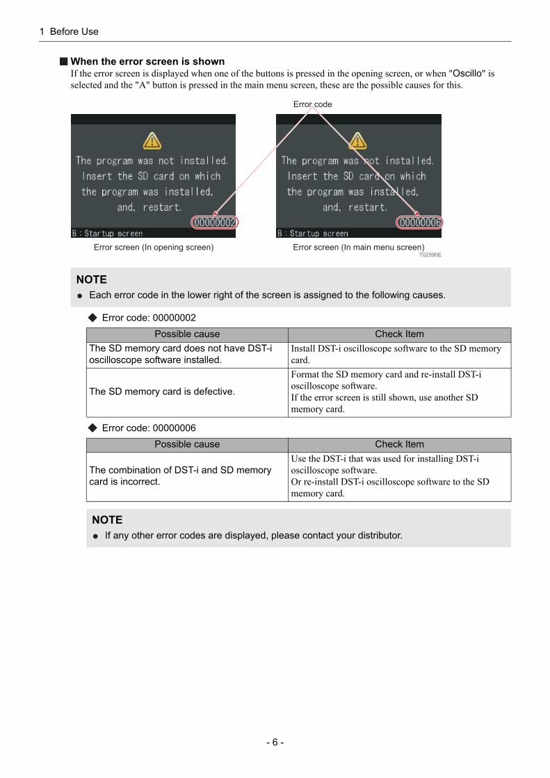
When the error screen is shownIf the error screen is displayed when one of the buttons is pressed in the opening screen, or when "Oscillo" is selected and the "A" button is pressed in the main menu screen, these are the possible causes for this.
Error code: 00000002
Error code: 00000006
NOTEEach error code in the lower right of the screen is assigned to the following causes.
Possible cause Check ItemThe SD memory card does not have DST-i oscilloscope software installed.
Install DST-i oscilloscope software to the SD memory card.
The SD memory card is defective.
Format the SD memory card and re-install DST-i oscilloscope software.If the error screen is still shown, use another SD memory card.
Possible cause Check Item
The combination of DST-i and SD memory card is incorrect.
Use the DST-i that was used for installing DST-i oscilloscope software.Or re-install DST-i oscilloscope software to the SD memory card.
NOTEIf any other error codes are displayed, please contact your distributor.
Error screen (In opening screen)T02590E
Error screen (In main menu screen)
Error code
1 Before Use
- 7 -
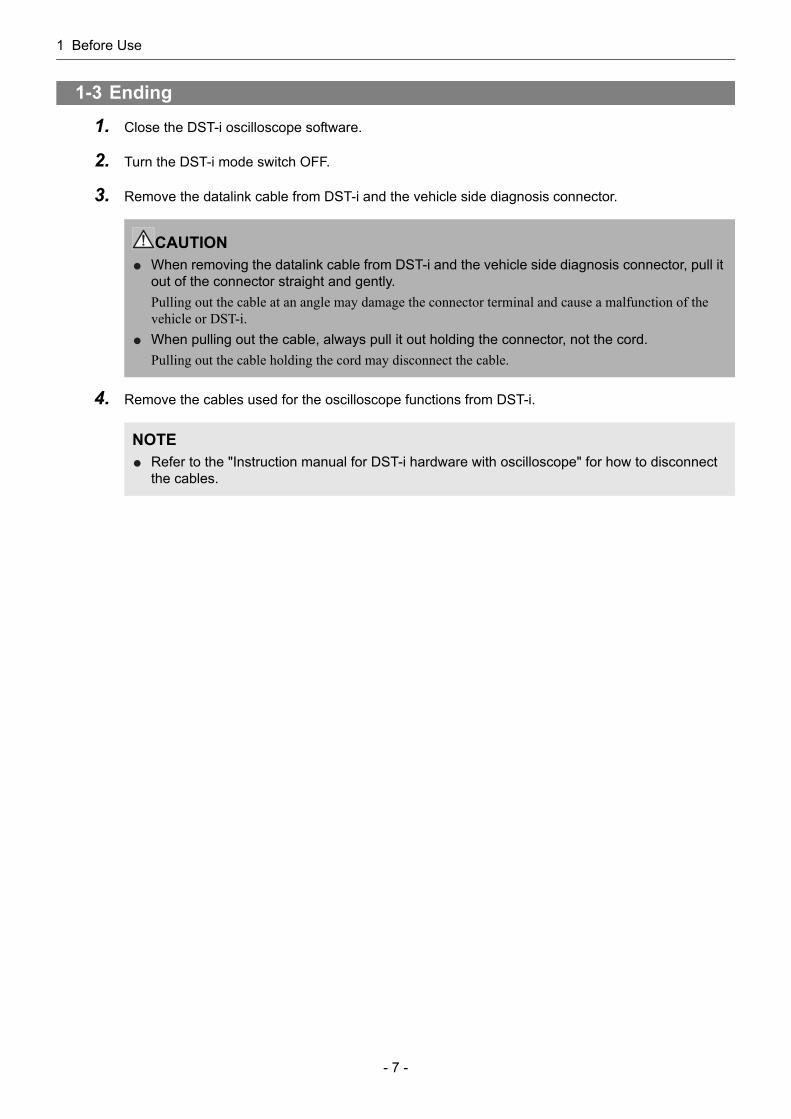
1. Close the DST-i oscilloscope software.
2. Turn the DST-i mode switch OFF.
3. Remove the datalink cable from DST-i and the vehicle side diagnosis connector.
4. Remove the cables used for the oscilloscope functions from DST-i.
1-3 Ending
CAUTIONWhen removing the datalink cable from DST-i and the vehicle side diagnosis connector, pull it out of the connector straight and gently.Pulling out the cable at an angle may damage the connector terminal and cause a malfunction of the vehicle or DST-i.When pulling out the cable, always pull it out holding the connector, not the cord.Pulling out the cable holding the cord may disconnect the cable.
NOTERefer to the "Instruction manual for DST-i hardware with oscilloscope" for how to disconnect the cables.

2 Functions of the DST-i Oscilloscope Software
- 8 -
2 Functions of the DST-i Oscilloscope Software
The DST-i oscilloscope software has two functions: "Waveform observation" and "Long duration data measurement".
Operation flow
2-1 Functions
Function Waveform observation Long duration data measurement
Details of function
Allows observation of signal waveform as an oscilloscope and saving the observation data.
Long duration waveform measurement data can be recorded and the recorded data can be saved.
Setting conditions
Trigger mode (Time range):• AUTO(500 ns/div to 5 ms/div)• NORMAL• SINGLE
Trigger mode (Time range):• AUTO(10 ms/div to 10 s/div)
Screen 1-screen display (real time displaying)Long duration displaying (as per recording time setting)Recording time: 1 min. to 40 hrs.
"AUTO"
"10 ms/div to 10 s/div""500 ns/div to 5 ms/div"
"NORMAL" "SINGLE"
T02417E
Set a trigger mode.
Time range is set.A trigger is set.
A trigger is set.
Recording long duration data measurement starts.
Long duration measurement data is saved.
Waveform observation data is saved. Recording conditions are set.
Recording time setting
Pretime setting
If above parameters are not set, they will be
automatically set depending on the time range.
A trigger is not set.A trigger is set.
Waveformobservation
Long durationdata measurement

2 Functions of the DST-i Oscilloscope Software
- 9 -
The following table shows operation and setting of waveform observation functions.
The following table shows operation and setting of long duration data measurement functions.
Waveform observation functions
Function Operation and setting Refer to:
Waveform observation
Stop/Start Page 11Time range setting Page 12Waveform display/non-display switching Page 13Ground position setting Page 13Voltage range setting Page 14Trigger setting Page 15Saving data Page 30
Long duration data measurement functions
Function Operation and setting Refer to:
Long duration data measurement
Recording time setting Page 23Pretime setting Page 24Trigger setting Page 26Saving data Page 30

3 Operation of the DST-i Oscilloscope Software
- 10 -
3 Operation of the DST-i Oscilloscope Software
This screen is used to observe the inputted waveforms.
The following figures show screen examples and the parts of the screen.
NOTEThe following explanation uses a screen that observes 4 channel waveforms using a 4-channel adapter set.The default condition of this product allows waveforms for 2 channels only.
3-1 Waveform observation
Screen configuration
T02323E
Trigger position: T mark
Trigger mode display
Channel 4 ground position
Channel 3 ground position
Channel 2 ground position
Channel 1 ground position
Time range display
Selection items
Channel 1 display
Channel 1 voltage range display
Channel 2 display
Channel 2 voltage range display Channel 3 display
Channel 3 voltage range display
Channel 4 voltage range display
Channel 4 display
Menu
Trigger slope display
Trigger level: Triangular mark
Trigger slope: Arrow mark
Trigger level display
Trigger channel display
Trigger position display
display
3 Operation of the DST-i Oscilloscope Software
- 11 -
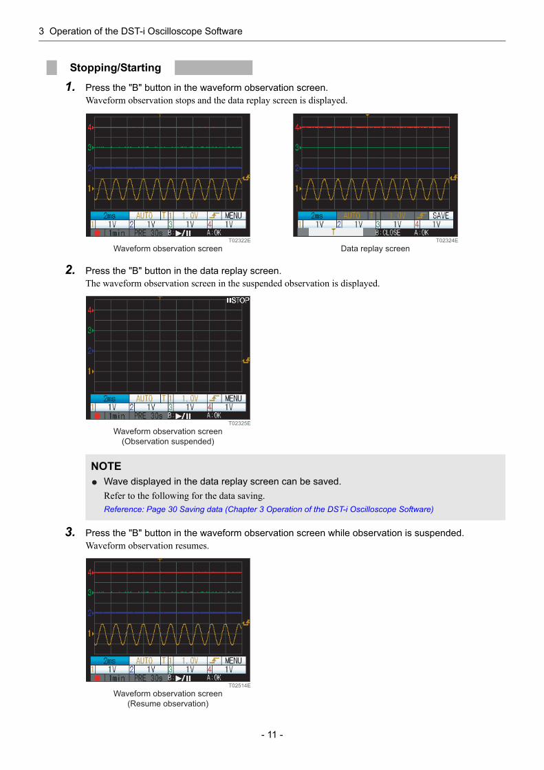
1. Press the "B" button in the waveform observation screen.Waveform observation stops and the data replay screen is displayed.
2. Press the "B" button in the data replay screen.The waveform observation screen in the suspended observation is displayed.
3. Press the "B" button in the waveform observation screen while observation is suspended.Waveform observation resumes.
Stopping/Starting
NOTEWave displayed in the data replay screen can be saved.Refer to the following for the data saving.Reference: Page 30 Saving data (Chapter 3 Operation of the DST-i Oscilloscope Software)
T02322E
Waveform observation screen Data replay screenT02324E
Waveform observation screen
(Observation suspended)
T02325E
T02514E
Waveform observation screen
(Resume observation)
3 Operation of the DST-i Oscilloscope Software
- 12 -
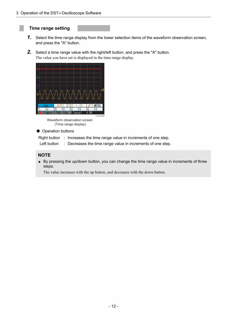
1. Select the time range display from the lower selection items of the waveform observation screen, and press the "A" button.
2. Select a time range value with the right/left button, and press the "A" button.The value you have set is displayed in the time range display.
Operation buttons
Time range setting
Right button : Increases the time range value in increments of one step.Left button : Decreases the time range value in increments of one step.
NOTEBy pressing the up/down button, you can change the time range value in increments of three steps.The value increases with the up button, and decreases with the down button.
T02326E
Waveform observation screen
(Time range display)

3 Operation of the DST-i Oscilloscope Software
- 13 -
1. Select the channel display from the lower selection items of the waveform observation screen, and press the "A" button.
2. Select display/non-display of waveforms with the right/left button, and press the "A" button.When you select OFF, OFF is displayed in the channel display.
Operation buttons
3. When you set the waveform display/non-display switching to ON, specify the ground position (0 V position) with the up/down button, and press the "A" button.
Operation buttons
Setting the channel (waveform display/non-display switching, ground position)
NOTESet "ON" to show waveforms and "OFF" to hide them.
Right button : Sets the waveform display/non-display switching to OFF.Left button : Sets the waveform display/non-display switching to ON.
Up button : Increases the ground position. (Only when the waveform display/non-display switching is set to ON)
Down button : Decreases the ground position. (Only when the waveform display/non-display switching is set to ON)
T02328E
Waveform observation screen
(Channel display)
T02440E
Waveform observation screen
(Ground position)
3 Operation of the DST-i Oscilloscope Software
- 14 -
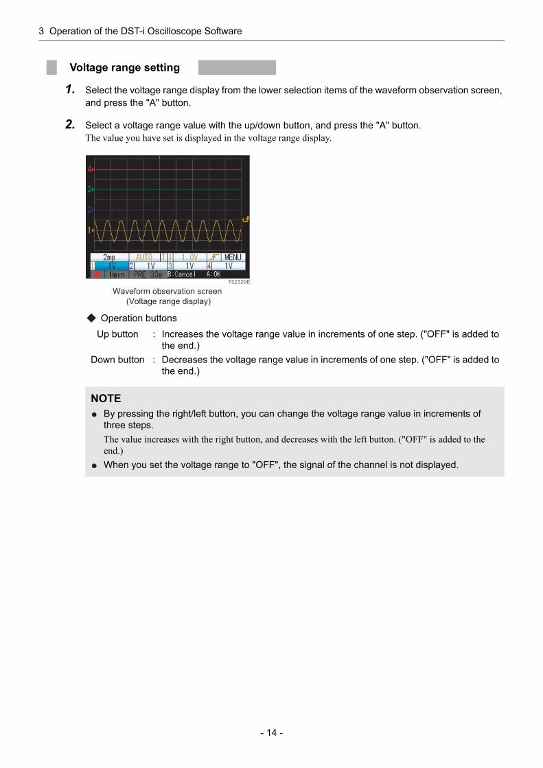
1. Select the voltage range display from the lower selection items of the waveform observation screen, and press the "A" button.
2. Select a voltage range value with the up/down button, and press the "A" button.The value you have set is displayed in the voltage range display.
Operation buttons
Voltage range setting
Up button : Increases the voltage range value in increments of one step. ("OFF" is added to the end.)
Down button : Decreases the voltage range value in increments of one step. ("OFF" is added to the end.)
NOTEBy pressing the right/left button, you can change the voltage range value in increments of three steps.The value increases with the right button, and decreases with the left button. ("OFF" is added to the end.)When you set the voltage range to "OFF", the signal of the channel is not displayed.
T02329E
Waveform observation screen
(Voltage range display)

3 Operation of the DST-i Oscilloscope Software
- 15 -
Various settings related to trigger can be made.• Trigger mode setting• Trigger channel setting• Trigger level setting• Trigger slope setting• Trigger position setting
Trigger mode settingTrigger mode can be set.
Setting items
1. Select the trigger mode display from the lower selection items of the waveform observation screen, and press the "A" button.
2. Select a trigger mode with the right/left button, and press the "A" button.The mode you have selected is displayed in the trigger mode display.
Operation buttons
Trigger setting
Item Description
AUTORenews the waveform after the designated trigger conditions are detected or after a certain time elapses. Setting the time range from 10 ms/div to 10 s/div allows long duration data measurement.
NORMALA waveform is displayed every time the designated trigger conditions are met.Under the conditions that no triggers can be set, no waveform will be shown. In the upper of the screen, "WAITING" is displayed.
SINGLE
Stops the trigger after displaying a waveform when designated trigger conditions are first met.Under the conditions that no triggers can be set, no waveform will be shown. In the upper of the screen, "WAITING" is displayed.
Right button : Moves the mode selection cursor to the right.Left button : Moves the mode selection cursor to the left.
T02331E
Waveform observation screen
(Trigger mode display)

3 Operation of the DST-i Oscilloscope Software
- 16 -
Trigger channel settingTrigger channels are switched over.
1. Select the trigger channel display from the lower selection items of the waveform observation screen, and press the "A" button.
2. Select a channel you want to set the trigger conditions with the right/left button, and press the "A" button.The channel you have selected is displayed in the trigger channel display.
Operation buttons
Trigger level settingA trigger level for a selected trigger channel is set.
1. Select the trigger level display from the lower selection items of the waveform observation screen, and press the "A" button.
2. Specify a trigger level with the up/down button, and press the "A" button.The trigger level you have set is displayed in the right side of the screen with a triangular mark.
Operation buttons
Right button : Moves the channel selection cursor to the right.Left button : Moves the channel selection cursor to the left.
Up button : Increases the trigger level.Down button : Decreases the trigger level.
T02330E
Waveform observation screen
(Trigger channel display)
T02332E
Waveform observation screen
(Trigger level display)
Trigger level: Triangular mark

3 Operation of the DST-i Oscilloscope Software
- 17 -
Trigger slope settingA trigger slope for selected trigger channels are switched over.
1. Select the trigger slope display from the lower selection items of the waveform observation screen, and press the "A" button.
2. Select rise/fall of the trigger slope with the right/left button, and press the "A" button.Marks of the rise/fall are displayed in the trigger slope display and at the right of the screen.
Operation buttons
Trigger position settingTrigger position for selected trigger channels is set.
1. Select the trigger position display from the lower selection items of the waveform observation screen, and press the "A" button.
2. Specify a trigger position with the right/left button, and press the "A" button.The trigger position you have set is displayed in the upper part of the screen with a T mark.
Operation buttons
Right button : Moves the slope selection cursor to the right.Left button : Moves the slope selection cursor to the left.
Right button : Moves the trigger position to the right.Left button : Moves the trigger position to the left.
T02333E
Trigger slope :
A rise mark or a fall mark.
Waveform observation screen
(Trigger slope display)
T02334J
Trigger position: T mark
Waveform observation screen
(Trigger position display)

3 Operation of the DST-i Oscilloscope Software
- 18 -
Long duration waveform measurement data can be recorded.Setting trigger mode to AUTO and time range from 10 ms/div to 10 s/div allows measuring a long duration data measurement.Data obtained by pressing the recording start mark cannot be displayed as a waveform after resetting the time range while replaying a data.
The following figures show screen examples and the parts of the screen.
3-2 Long duration data measurement
Long duration data measurement flow
Screen configuration
T02263E
1. Set the trigger mode to "AUTO".
2. Set the time range from 10 ms/div to 10 s/div.
3. Set the long duration data measurement conditions.
4. Set the trigger.
5. Start recording long duration data measurement.
6. Save the long duration measurement data.
Refer to : Trigger mode setting
Refer to : Time range setting
Refer to : Long duration data measurement conditions
Refer to : Trigger setting
Refer to : Starting recording
Refer to : Data saving
T02355E
Pretime displayRecording start mark
Recording time
display
Trigger mode display
Channel 4 ground position
Channel 3 ground position
Channel 2 ground position
Channel 1 ground position
Time range display
Selection items
Channel 1 display
Channel 1 voltage range display Channel 2 display Channel 2 voltage range display
Channel 3 display
Channel 3 voltage range display
Channel 4 voltage range display
Channel 4 display
Menu
Trigger slope display
Trigger level display
Trigger channel display
Trigger position display

3 Operation of the DST-i Oscilloscope Software
- 19 -
Time range, Sampling rate, Recording time and measurement data file size
1. Select the trigger mode display from the lower selection items of the waveform observation screen, and press the "A" button.
2. Select "AUTO" with the right/left button, and press the "A" button."AUTO" is displayed in the trigger mode display.
Operation buttons
Time range Sampling rate(Fixed)
Maximum recording time (per 1 recording)
Maximum file size(per 1 recording)
10 s/div 32 S/s 40 hrs. Approx. 20 MB5 s/div 64 S/s 40 hrs. Approx. 35 MB2 s/div 160 S/s 40 hrs. Approx. 90 MB1 s/div 320 S/s 40 hrs. Approx. 180 MB
500 ms/div 640 S/s 40 hrs. Approx. 360 MB200 ms/div 1.6 kS/s 20 hrs. Approx. 440 MB100 ms/div 3.2 kS/s 10 hrs. Approx. 440 MB50 ms/div 6.4 kS/s 5 hrs. Approx. 440 MB20 ms/div 16 kS/s 2 min. (ch.2: 4 min.) Approx. 8 MB10 ms/div 32 kS/s 1 min. (ch.2: 2 min.) Approx. 8 MB
NOTEThe sampling rate and the recording time differs depending on the time range to be set.Time can be record differs depending on the sampling rate.The more detail that is recorded, the shorter the maximum recording time.Use PC oscilloscope software for recording the further detailed data.
Trigger mode setting
Right button : Moves the mode selection cursor to the right.Left button : Moves the mode selection cursor to the left.
T02441E
Waveform observation screen
(Trigger mode display)
3 Operation of the DST-i Oscilloscope Software
- 20 -
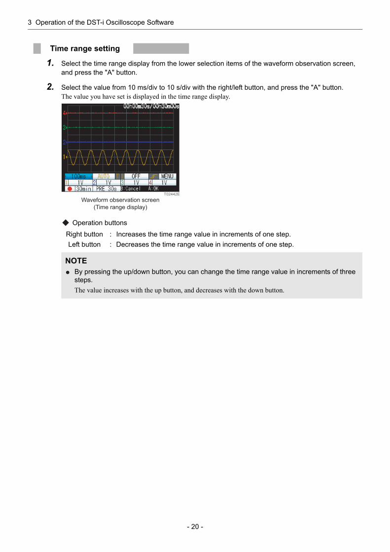
1. Select the time range display from the lower selection items of the waveform observation screen, and press the "A" button.
2. Select the value from 10 ms/div to 10 s/div with the right/left button, and press the "A" button.The value you have set is displayed in the time range display.
Operation buttons
Time range setting
Right button : Increases the time range value in increments of one step.Left button : Decreases the time range value in increments of one step.
NOTEBy pressing the up/down button, you can change the time range value in increments of three steps.The value increases with the up button, and decreases with the down button.
T02442E
Waveform observation screen
(Time range display)
3 Operation of the DST-i Oscilloscope Software
- 21 -
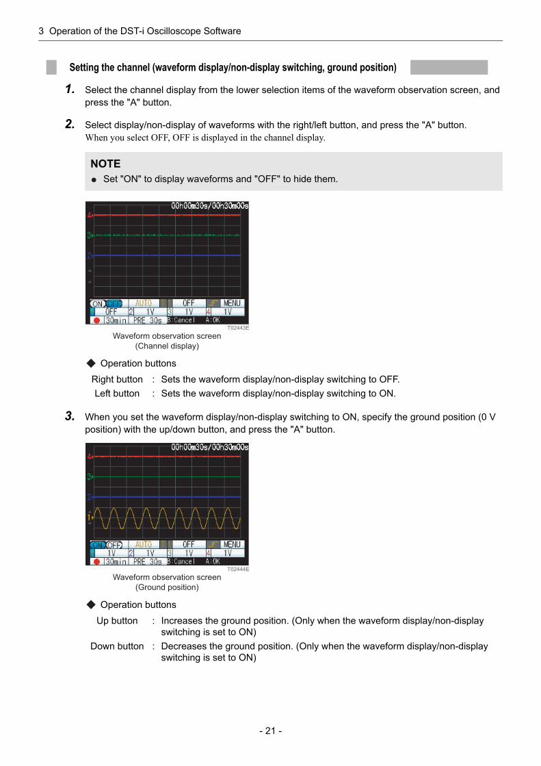
1. Select the channel display from the lower selection items of the waveform observation screen, and press the "A" button.
2. Select display/non-display of waveforms with the right/left button, and press the "A" button.When you select OFF, OFF is displayed in the channel display.
Operation buttons
3. When you set the waveform display/non-display switching to ON, specify the ground position (0 V position) with the up/down button, and press the "A" button.
Operation buttons
Setting the channel (waveform display/non-display switching, ground position)
NOTESet "ON" to display waveforms and "OFF" to hide them.
Right button : Sets the waveform display/non-display switching to OFF.Left button : Sets the waveform display/non-display switching to ON.
Up button : Increases the ground position. (Only when the waveform display/non-display switching is set to ON)
Down button : Decreases the ground position. (Only when the waveform display/non-display switching is set to ON)
T02443E
Waveform observation screen
(Channel display)
T02444E
Waveform observation screen
(Ground position)
3 Operation of the DST-i Oscilloscope Software
- 22 -
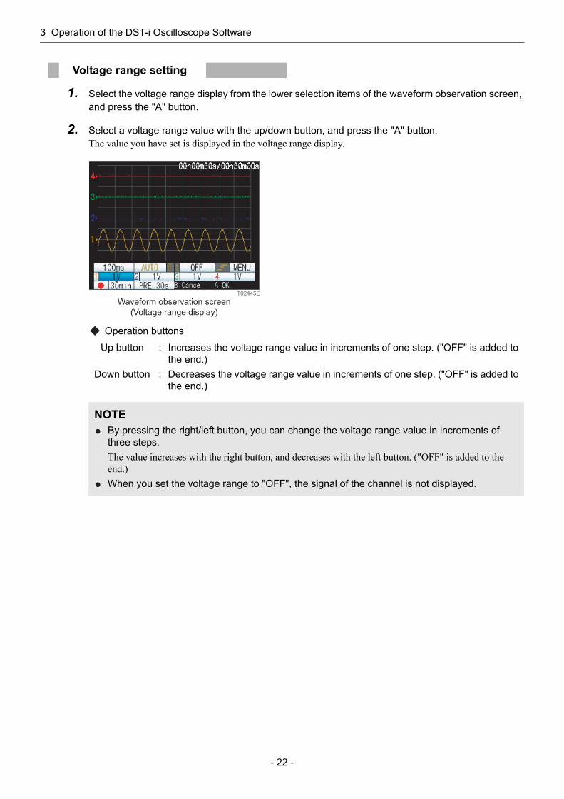
1. Select the voltage range display from the lower selection items of the waveform observation screen, and press the "A" button.
2. Select a voltage range value with the up/down button, and press the "A" button.The value you have set is displayed in the voltage range display.
Operation buttons
Voltage range setting
Up button : Increases the voltage range value in increments of one step. ("OFF" is added to the end.)
Down button : Decreases the voltage range value in increments of one step. ("OFF" is added to the end.)
NOTEBy pressing the right/left button, you can change the voltage range value in increments of three steps.The value increases with the right button, and decreases with the left button. ("OFF" is added to the end.)When you set the voltage range to "OFF", the signal of the channel is not displayed.
T02445E
Waveform observation screen
(Voltage range display)
3 Operation of the DST-i Oscilloscope Software
- 23 -
This screen allows setting of various conditions for long duration data measurement.
Recording time settingThe recording time can be set.
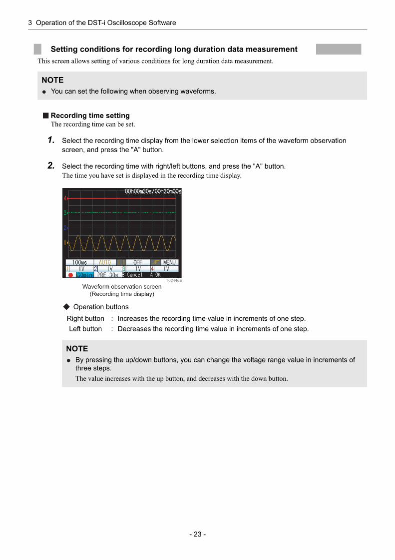
1. Select the recording time display from the lower selection items of the waveform observation screen, and press the "A" button.
2. Select the recording time with right/left buttons, and press the "A" button.The time you have set is displayed in the recording time display.
Operation buttons
Setting conditions for recording long duration data measurement
NOTEYou can set the following when observing waveforms.
Right button : Increases the recording time value in increments of one step.Left button : Decreases the recording time value in increments of one step.
NOTEBy pressing the up/down buttons, you can change the voltage range value in increments of three steps.The value increases with the up button, and decreases with the down button.
T02446E
Waveform observation screen
(Recording time display)
3 Operation of the DST-i Oscilloscope Software
- 24 -
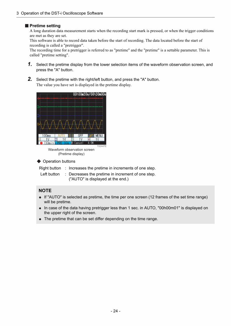
Pretime settingA long duration data measurement starts when the recording start mark is pressed, or when the trigger conditions are met as they are set.This software is able to record data taken before the start of recording. The data located before the start of recording is called a "pretrigger".The recording time for a pretrigger is referred to as "pretime" and the "pretime" is a settable parameter. This is called "pretime setting".
1. Select the pretime display from the lower selection items of the waveform observation screen, and press the "A" button.
2. Select the pretime with the right/left button, and press the "A" button.The value you have set is displayed in the pretime display.
Operation buttons
Right button : Increases the pretime in increments of one step.Left button : Decreases the pretime in increment of one step.
("AUTO" is displayed at the end.)
NOTEIf "AUTO" is selected as pretime, the time per one screen (12 frames of the set time range) will be pretime.In case of the data having pretrigger less than 1 sec. in AUTO, "00h00m01" is displayed on the upper right of the screen.The pretime that can be set differ depending on the time range.
T02447E
Waveform observation screen
(Pretime display)
3 Operation of the DST-i Oscilloscope Software
- 25 -
Long duration measurement data can be recorded to an SD memory card.
<To record without a start trigger>
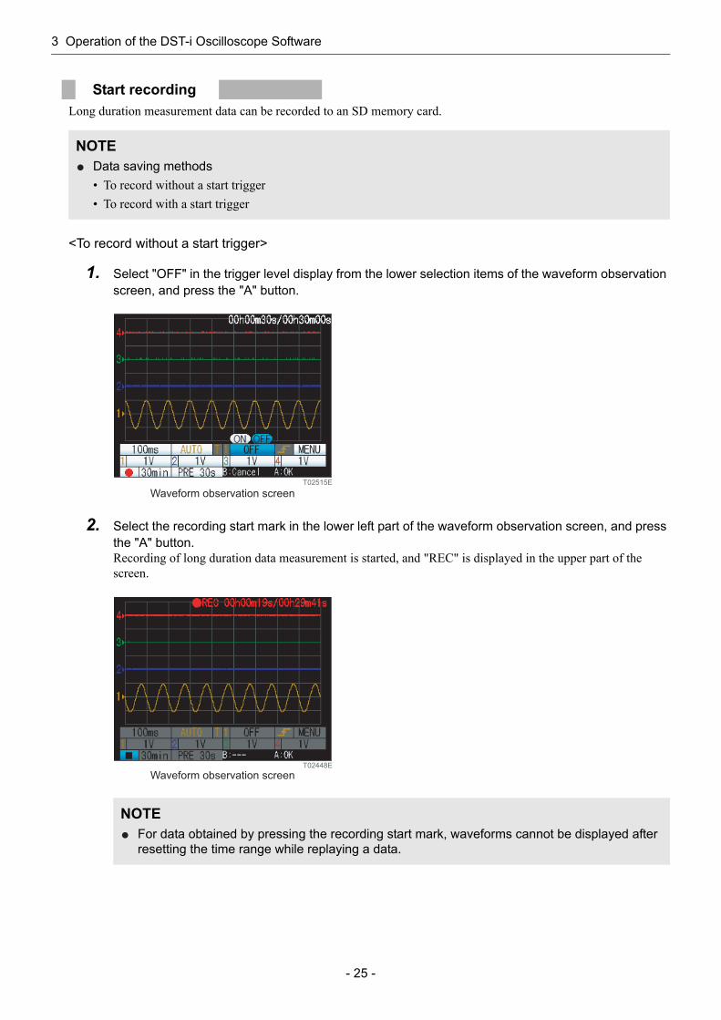
1. Select "OFF" in the trigger level display from the lower selection items of the waveform observation screen, and press the "A" button.
2. Select the recording start mark in the lower left part of the waveform observation screen, and press the "A" button.Recording of long duration data measurement is started, and "REC" is displayed in the upper part of the screen.
Start recording
NOTEData saving methods• To record without a start trigger• To record with a start trigger
NOTEFor data obtained by pressing the recording start mark, waveforms cannot be displayed after resetting the time range while replaying a data.
T02515E
Waveform observation screen
T02448E
Waveform observation screen
3 Operation of the DST-i Oscilloscope Software
- 26 -
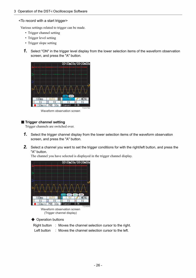
<To record with a start trigger>
Various settings related to trigger can be made.• Trigger channel setting• Trigger level setting• Trigger slope setting
1. Select "ON" in the trigger level display from the lower selection items of the waveform observation screen, and press the "A" button.
Trigger channel settingTrigger channels are switched over.
1. Select the trigger channel display from the lower selection items of the waveform observation screen, and press the "A" button.
2. Select a channel you want to set the trigger conditions for with the right/left button, and press the "A" button.The channel you have selected is displayed in the trigger channel display.
Operation buttons
Right button : Moves the channel selection cursor to the right.Left button : Moves the channel selection cursor to the left.
T02479E
Waveform observation screen
T02464E
Waveform observation screen
(Trigger channel display)

3 Operation of the DST-i Oscilloscope Software
- 27 -
Trigger level settingA trigger level for a selected trigger channel is set.
1. Select the trigger level display from the lower selection items of the waveform observation screen, and press the "A" button.
2. Specify a trigger level with the up/down button, and press the "A" button.The trigger level you have set is displayed in the right side of the screen with a triangular mark.
Operation buttons
Trigger slope settingA trigger slope for selected trigger channels are switched over.
1. Select the trigger slope display from the lower selection items of the waveform observation screen, and press the "A" button.
2. Select rise/fall of the trigger slope with the right/left button, and press the "A" button.Marks of the rise/fall are displayed in the trigger slope display and at the right of the screen.
Operation buttons
Up button : Increase the trigger level.Down button : Decrease the trigger level.
Right button : Moves the slope selection cursor to the right.Left button : Moves the slope selection cursor to the left.
T02465E
Waveform observation screen
(Trigger level display)
Trigger level: Triangular mark
T02466E
Trigger slope :
A rise mark or a fall mark.
Waveform observation screen
(Trigger slope display)
3 Operation of the DST-i Oscilloscope Software
- 28 -
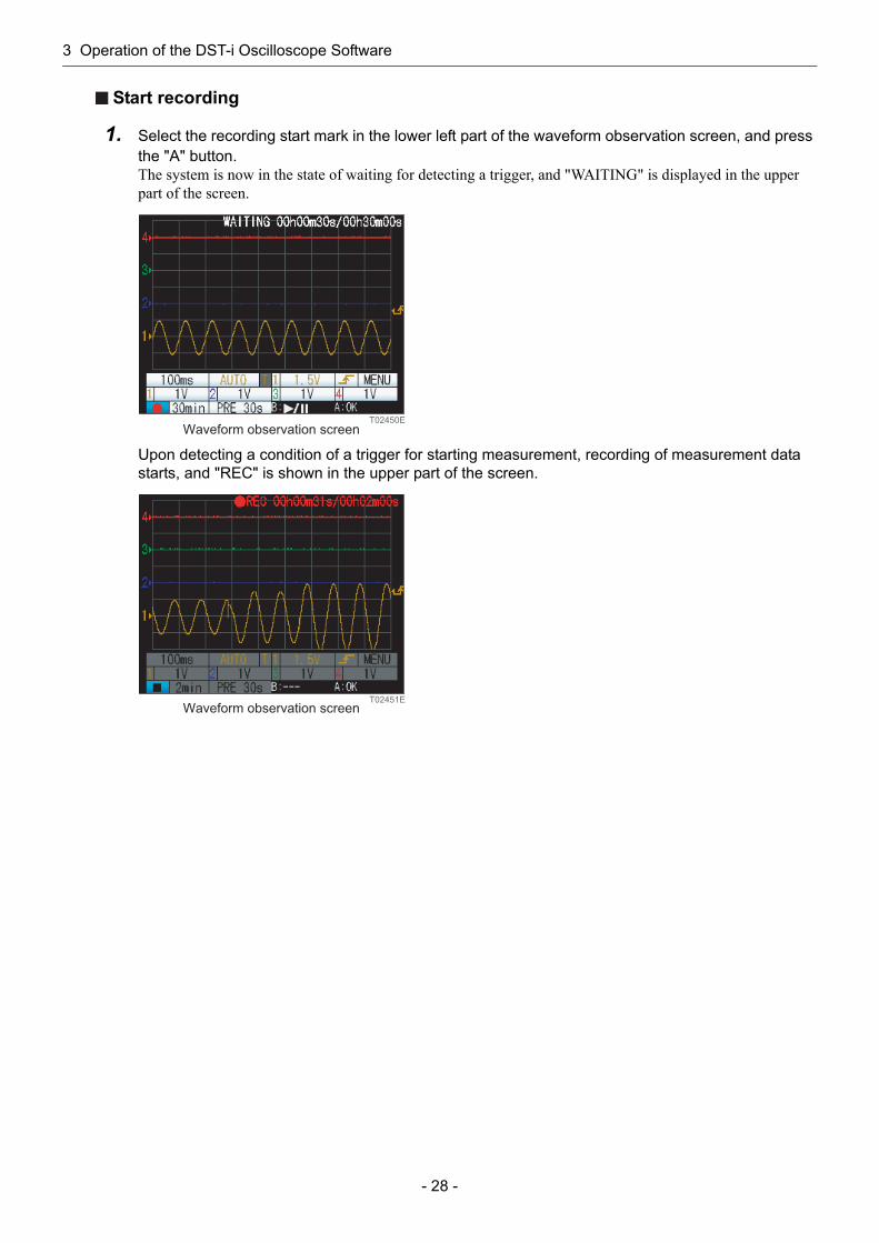
Start recording
1. Select the recording start mark in the lower left part of the waveform observation screen, and press the "A" button.The system is now in the state of waiting for detecting a trigger, and "WAITING" is displayed in the upper part of the screen.
Upon detecting a condition of a trigger for starting measurement, recording of measurement data starts, and "REC" is shown in the upper part of the screen.
T02450E
Waveform observation screen
T02451EWaveform observation screen
3 Operation of the DST-i Oscilloscope Software
- 29 -
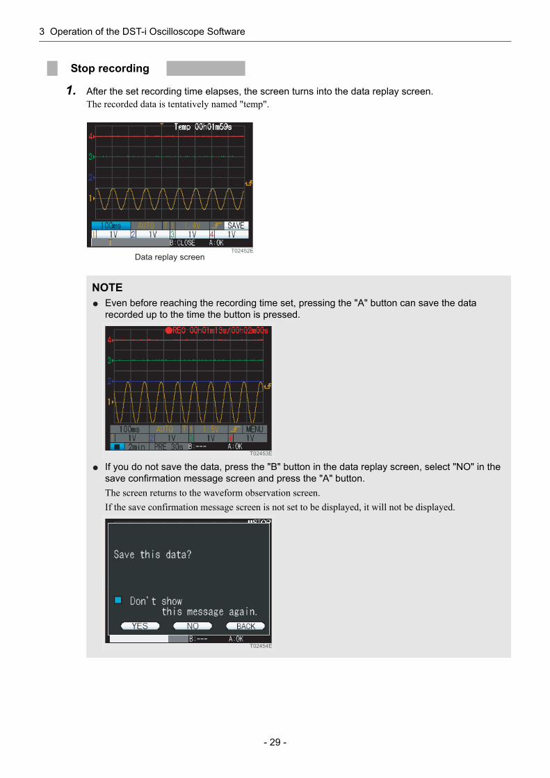
1. After the set recording time elapses, the screen turns into the data replay screen.The recorded data is tentatively named "temp".
Stop recording
NOTEEven before reaching the recording time set, pressing the "A" button can save the data recorded up to the time the button is pressed.
If you do not save the data, press the "B" button in the data replay screen, select "NO" in the save confirmation message screen and press the "A" button.The screen returns to the waveform observation screen.If the save confirmation message screen is not set to be displayed, it will not be displayed.
T02452E
Data replay screen
T02453E
T02454E
3 Operation of the DST-i Oscilloscope Software
- 30 -
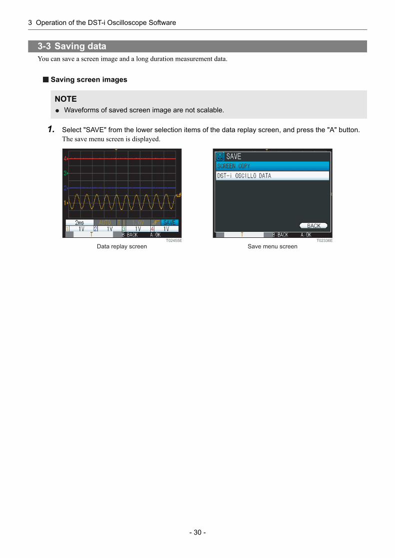
You can save a screen image and a long duration measurement data.
Saving screen images
1. Select "SAVE" from the lower selection items of the data replay screen, and press the "A" button.The save menu screen is displayed.
3-3 Saving data
NOTEWaveforms of saved screen image are not scalable.
T02455E
Data replay screenT02336E
Save menu screen
3 Operation of the DST-i Oscilloscope Software
- 31 -
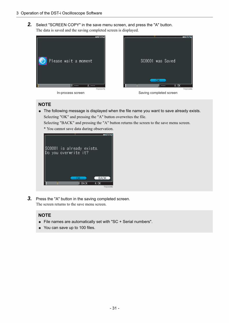
2. Select "SCREEN COPY" in the save menu screen, and press the "A" button.The data is saved and the saving completed screen is displayed.
3. Press the "A" button in the saving completed screen.The screen returns to the save menu screen.
NOTEThe following message is displayed when the file name you want to save already exists.Selecting "OK" and pressing the "A" button overwrites the file.Selecting "BACK" and pressing the "A" button returns the screen to the save menu screen.* You cannot save data during observation.
NOTEFile names are automatically set with "SC + Serial numbers".You can save up to 100 files.
T02337E
In-process screen
T02338E
Saving completed screen
T02339E
3 Operation of the DST-i Oscilloscope Software
- 32 -
Saving long duration measurement data
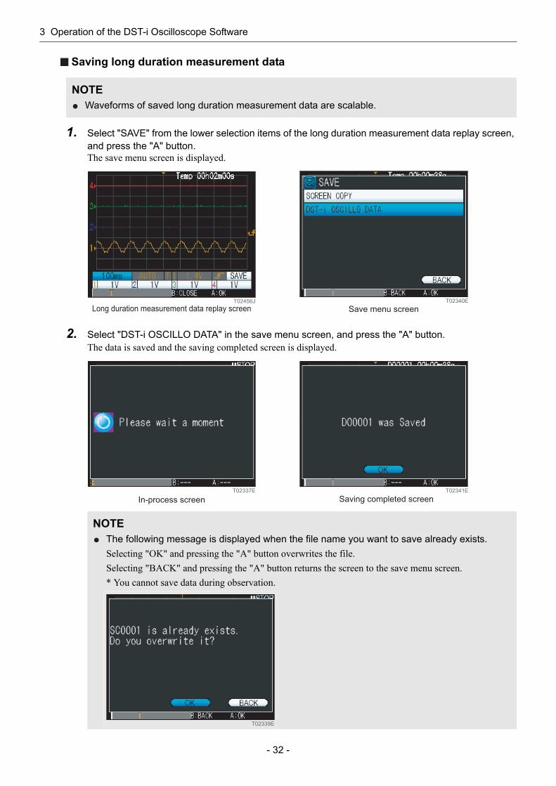
1. Select "SAVE" from the lower selection items of the long duration measurement data replay screen, and press the "A" button.The save menu screen is displayed.
2. Select "DST-i OSCILLO DATA" in the save menu screen, and press the "A" button.The data is saved and the saving completed screen is displayed.
NOTEWaveforms of saved long duration measurement data are scalable.
NOTEThe following message is displayed when the file name you want to save already exists.Selecting "OK" and pressing the "A" button overwrites the file.Selecting "BACK" and pressing the "A" button returns the screen to the save menu screen.* You cannot save data during observation.
T02456J
Long duration measurement data replay screenT02340E
Save menu screen
T02337E
In-process screen
T02341E
Saving completed screen
T02339E
3 Operation of the DST-i Oscilloscope Software
- 33 -
3. Press the "A" button in the saving completed screen.The screen returns to the save menu screen.
NOTEFile names are automatically set with "DO + Serial numbers".You can save up to 100 files.

3 Operation of the DST-i Oscilloscope Software
- 34 -
You can retrieve and replay a screen image and a long duration measurement data.
Retrieving screen images
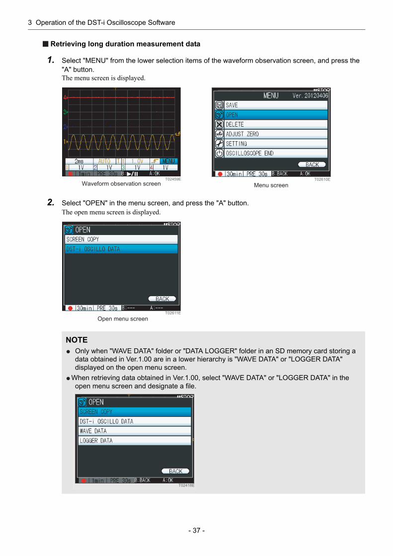
1. Select "MENU" from the lower selection items of the waveform observation screen, and press the "A" button.The menu screen is displayed.
3-4 Retrieving data
NOTEWaveforms of the screen image are not scalable.
T02459E
Waveform observation screenT02610E
Menu screen
3 Operation of the DST-i Oscilloscope Software
- 35 -
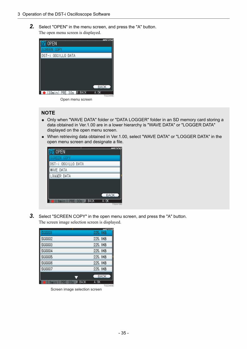
2. Select "OPEN" in the menu screen, and press the "A" button.The open menu screen is displayed.
3. Select "SCREEN COPY" in the open menu screen, and press the "A" button.The screen image selection screen is displayed.
NOTEOnly when "WAVE DATA" folder or "DATA LOGGER" folder in an SD memory card storing a data obtained in Ver.1.00 are in a lower hierarchy is "WAVE DATA" or "LOGGER DATA" displayed on the open menu screen.When retrieving data obtained in Ver.1.00, select "WAVE DATA" or "LOGGER DATA" in the open menu screen and designate a file.
T02344E
Open menu screen
T02418E
T02345E
Screen image selection screen

3 Operation of the DST-i Oscilloscope Software
- 36 -
4. Select the file name you want to replay on the screen image selection screen, and press the "A" button.The replay screen of the screen image you have selected is displayed.
5. Press the "A" button or the "B" button on the screen image replay screen.The screen returns to the screen image selection screen.
NOTEThe operational guidance and the file name of the screen image which is being replayed are displayed in the guidance area alternately.
T02346E
Screen image replay screen
3 Operation of the DST-i Oscilloscope Software
- 37 -
Retrieving long duration measurement data
1. Select "MENU" from the lower selection items of the waveform observation screen, and press the "A" button.The menu screen is displayed.
2. Select "OPEN" in the menu screen, and press the "A" button.The open menu screen is displayed.
NOTEOnly when "WAVE DATA" folder or "DATA LOGGER" folder in an SD memory card storing a data obtained in Ver.1.00 are in a lower hierarchy is "WAVE DATA" or "LOGGER DATA" displayed on the open menu screen.
When retrieving data obtained in Ver.1.00, select "WAVE DATA" or "LOGGER DATA" in the open menu screen and designate a file.
T02459E
Waveform observation screenT02610E
Menu screen
T02611E
Open menu screen
T02418E
3 Operation of the DST-i Oscilloscope Software
- 38 -
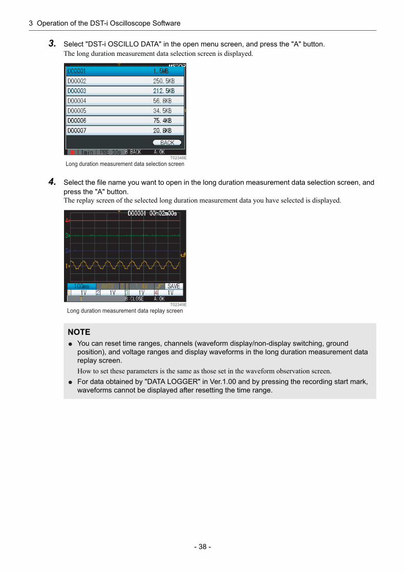
3. Select "DST-i OSCILLO DATA" in the open menu screen, and press the "A" button.The long duration measurement data selection screen is displayed.
4. Select the file name you want to open in the long duration measurement data selection screen, and press the "A" button.The replay screen of the selected long duration measurement data you have selected is displayed.
NOTEYou can reset time ranges, channels (waveform display/non-display switching, ground position), and voltage ranges and display waveforms in the long duration measurement data replay screen.How to set these parameters is the same as those set in the waveform observation screen.For data obtained by "DATA LOGGER" in Ver.1.00 and by pressing the recording start mark, waveforms cannot be displayed after resetting the time range.
T02348E
Long duration measurement data selection screen
T02349E
Long duration measurement data replay screen

3 Operation of the DST-i Oscilloscope Software
- 39 -
5. Select a scroll bar in the long duration measurement data replay screen, and press the "A" button.
6. Press the "B" button in the long duration measurement data replay screen.The screen returns to the long duration measurement data selection screen.
NOTEUse the right/left buttons to manually move frame by frame through long duration measurement data.Move forward and backward through frames with the right and left buttons, respectively.Use the up/down buttons to move through the "Left end of the scroll bar", "Recording start position", and "Right of the scroll bar" selections.
T02462E
Long duration measurement data replay screen
3 Operation of the DST-i Oscilloscope Software
- 40 -
You can delete a screen image and a long duration measurement data.
Deleting screen images
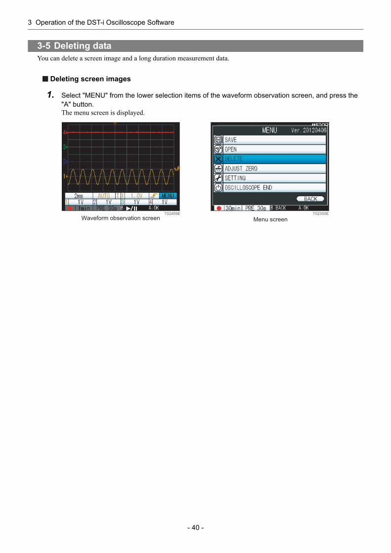
1. Select "MENU" from the lower selection items of the waveform observation screen, and press the "A" button.The menu screen is displayed.
3-5 Deleting data
T02459E
Waveform observation screenT02350E
Menu screen
3 Operation of the DST-i Oscilloscope Software
- 41 -
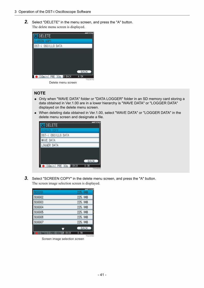
2. Select "DELETE" in the menu screen, and press the "A" button.The delete menu screen is displayed.
3. Select "SCREEN COPY" in the delete menu screen, and press the "A" button.The screen image selection screen is displayed.
NOTEOnly when "WAVE DATA" folder or "DATA LOGGER" folder in an SD memory card storing a data obtained in Ver.1.00 are in a lower hierarchy is "WAVE DATA" or "LOGGER DATA" displayed on the delete menu screen.When deleting data obtained in Ver.1.00, select "WAVE DATA" or "LOGGER DATA" in the delete menu screen and designate a file.
T02351E
Delete menu screen
T02460E
T02345E
Screen image selection screen
3 Operation of the DST-i Oscilloscope Software
- 42 -
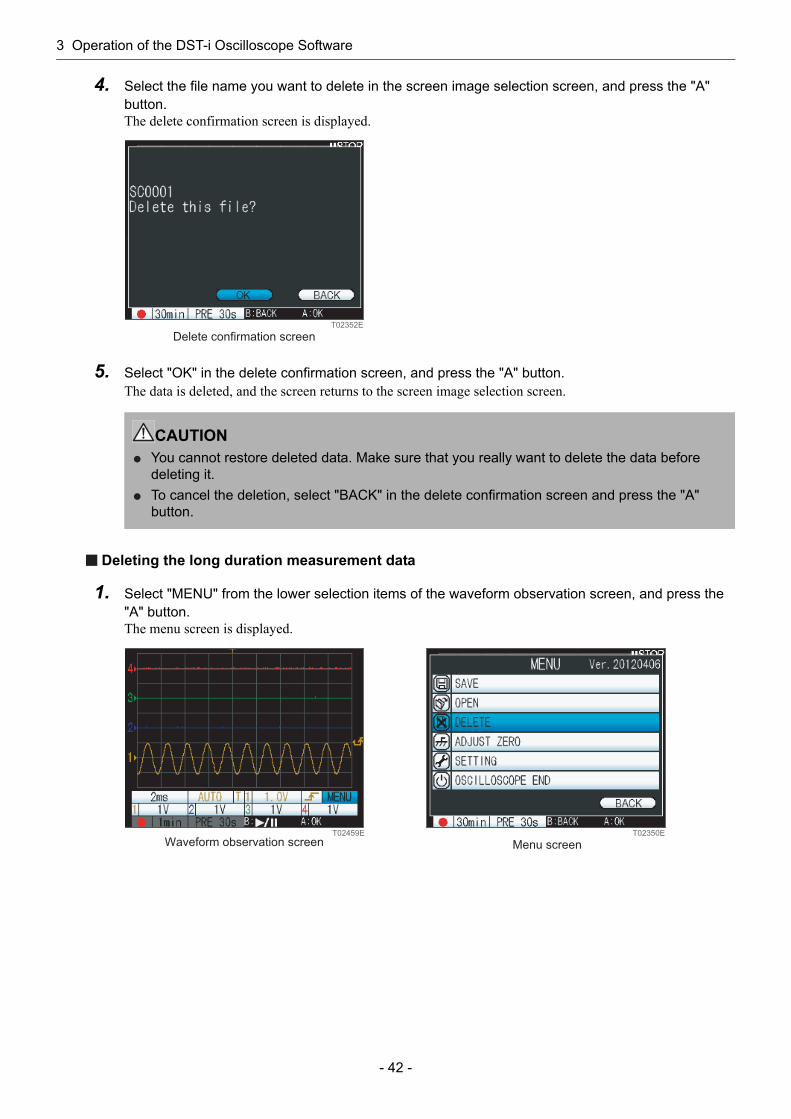
4. Select the file name you want to delete in the screen image selection screen, and press the "A" button.The delete confirmation screen is displayed.
5. Select "OK" in the delete confirmation screen, and press the "A" button.The data is deleted, and the screen returns to the screen image selection screen.
Deleting the long duration measurement data
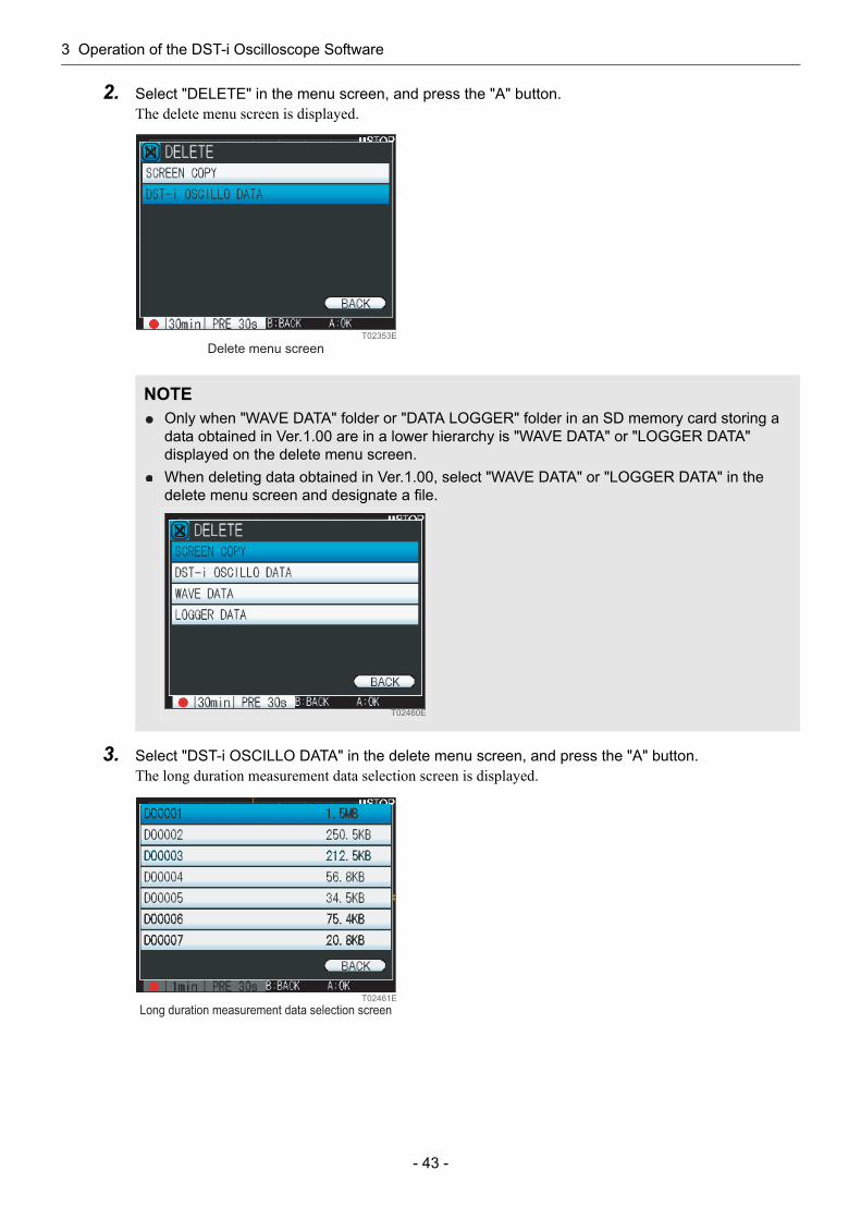
1. Select "MENU" from the lower selection items of the waveform observation screen, and press the "A" button.The menu screen is displayed.
CAUTIONYou cannot restore deleted data. Make sure that you really want to delete the data before deleting it.To cancel the deletion, select "BACK" in the delete confirmation screen and press the "A" button.
T02352E
Delete confirmation screen
T02459E
Waveform observation screenT02350E
Menu screen
3 Operation of the DST-i Oscilloscope Software
- 43 -
2. Select "DELETE" in the menu screen, and press the "A" button.The delete menu screen is displayed.
3. Select "DST-i OSCILLO DATA" in the delete menu screen, and press the "A" button.The long duration measurement data selection screen is displayed.
NOTEOnly when "WAVE DATA" folder or "DATA LOGGER" folder in an SD memory card storing a data obtained in Ver.1.00 are in a lower hierarchy is "WAVE DATA" or "LOGGER DATA" displayed on the delete menu screen.When deleting data obtained in Ver.1.00, select "WAVE DATA" or "LOGGER DATA" in the delete menu screen and designate a file.
T02353E
Delete menu screen
T02460E
T02461E
Long duration measurement data selection screen

3 Operation of the DST-i Oscilloscope Software
- 44 -
4. Select a file to be deleted in the long duration measurement data selection screen, and press the "A" button.The delete confirmation screen is displayed.
5. Select "OK" in the delete confirmation screen, and press the "A" button.Delete data and return to the long duration measurement data selection screen.
CAUTIONYou cannot restore deleted data. Make sure that you really want to delete the data before deleting it.To cancel the deletion, select "BACK" in the delete confirmation screen and press the "A" button.
T02612E
Delete confirmation screen
3 Operation of the DST-i Oscilloscope Software
- 45 -
You can readjust the zero point of the oscilloscope.Perform zero point correction after removing all the cables for the oscilloscope.
1. Check that the waveform of each channel is horizontal at the 0 V position.
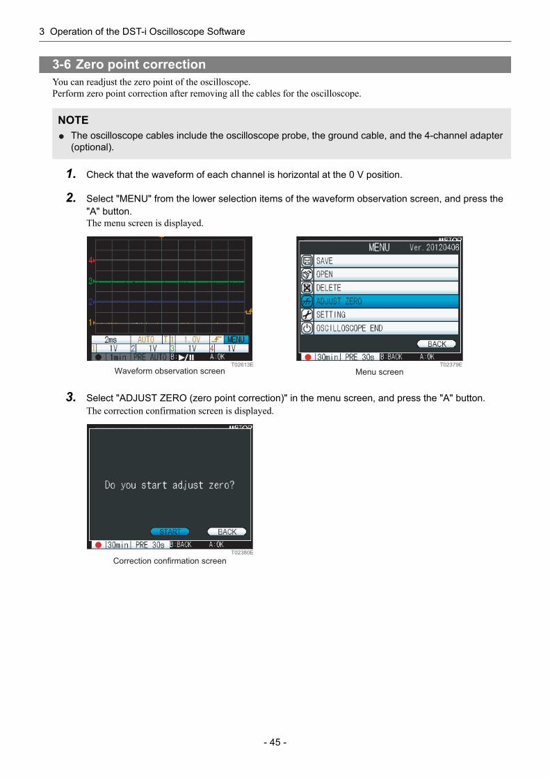
2. Select "MENU" from the lower selection items of the waveform observation screen, and press the "A" button.The menu screen is displayed.
3. Select "ADJUST ZERO (zero point correction)" in the menu screen, and press the "A" button.The correction confirmation screen is displayed.
3-6 Zero point correction
NOTEThe oscilloscope cables include the oscilloscope probe, the ground cable, and the 4-channel adapter (optional).
T02613E
Waveform observation screenT02379E
Menu screen
T02380E
Correction confirmation screen

3 Operation of the DST-i Oscilloscope Software
- 46 -
4. Select "START" in the correction confirmation screen, and press the "A" button.When the zero point correction is completed, the screen returns to the menu screen.
NOTETo cancel zero point correction, select "BACK" in the correction confirmation screen, and press the "A" button.
T02337E
In-process screen
3 Operation of the DST-i Oscilloscope Software
- 47 -
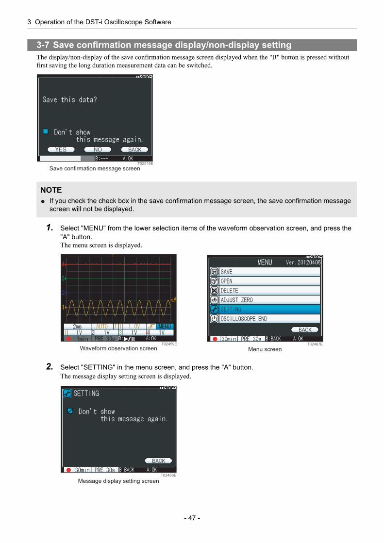
The display/non-display of the save confirmation message screen displayed when the "B" button is pressed without first saving the long duration measurement data can be switched.
1. Select "MENU" from the lower selection items of the waveform observation screen, and press the "A" button.The menu screen is displayed.
2. Select "SETTING" in the menu screen, and press the "A" button.The message display setting screen is displayed.
3-7 Save confirmation message display/non-display setting
NOTEIf you check the check box in the save confirmation message screen, the save confirmation message screen will not be displayed.
Save confirmation message screenT02516E
T02459E
Waveform observation screenT02467E
Menu screen
T02468E
Message display setting screen
3 Operation of the DST-i Oscilloscope Software
- 48 -
3. Select a check box in the message display setting screen, and press the "A" button.Check mark is displayed in a check box.
4. Select "BACK" in the message display setting screen, and press the "A" button.The screen returns to the menu screen.Subsequently, the save confirmation message screen is not displayed.
NOTEUncheck the check box to display the save confirmation message screen again.
3 Operation of the DST-i Oscilloscope Software
- 49 -
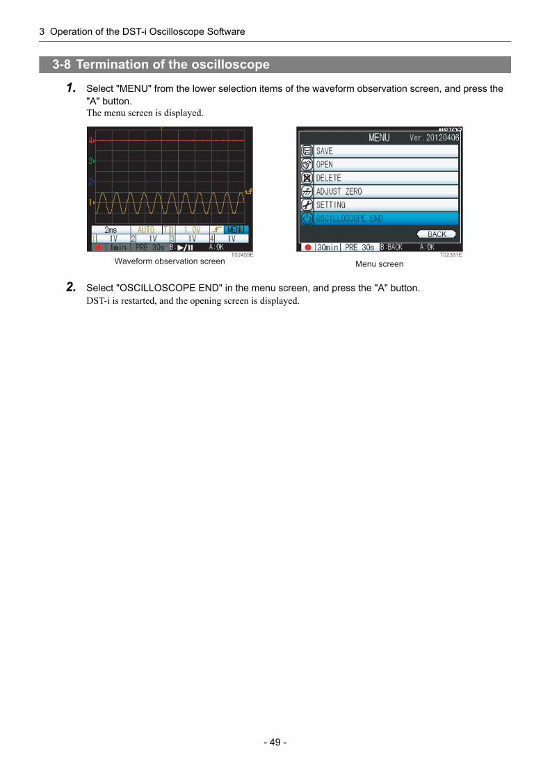
1. Select "MENU" from the lower selection items of the waveform observation screen, and press the "A" button.The menu screen is displayed.
2. Select "OSCILLOSCOPE END" in the menu screen, and press the "A" button.DST-i is restarted, and the opening screen is displayed.
3-8 Termination of the oscilloscope
T02459E
Waveform observation screenT02381E
Menu screen

4 Troubleshooting
- 50 -
4 Troubleshooting
If the PC freezes while using the DST-i oscilloscope software, perform the following procedure.
1. Turn the DST-i mode switch OFF.If the PC still freezes, please contact your distributor.
2. Turn the DST-i mode switch ON to restart the software.If the PC still freezes, please contact your distributor.
4-1 If the screen freezes while using
4-2 If the system message is displayedMessage Check point
SD Card is not found. Please insert SD Card.
An SD memory card was not found while saving data.Insert an SD memory card into DST-i.
SD Card is Full. Could not create new file.
There was not enough space in the SD memory card while saving data. (There is less than 300 KB of free space.)Delete unnecessary data.* You cannot save data during measurement.
Adjusting failure. A failure occurred during execution of zero point correction.Please contact your distributor.
Error. Maximum number of files.
The maximum number of files (100) that can be saved is exceeded.Delete unnecessary data.* You cannot save data during measurement.
Error, SD is write-protected.The SD memory card is write-protected.Cancel the write protection.* You cannot save data during measurement.
Failed to read file. The file was not correct during readout of the saved data.Check the version of the DST-i oscilloscope software.

4 Troubleshooting
- 51 -
DENSO Overseas Subsidiary Company & TAS CORPORATION name/Address
Tel/Fax
DENSO AUTOMOTIVE SYSTEMS AUSTRALIA PTY. LTD.Address: 2-46 Merrindale Drive, Croydon, Victoria 3136, Australia
Sales: Tel: +61-3-8761-1400 Fax: +61-3-8761-1505 Service: Tel: +61-3-8761-1449 Fax: +61-3-8761-1505
DENSO INTERNATIONAL ASIA PTE. LTD.Address: 51 Science Park Road, #01-19 The Aries, Science Park II,
Singapore 117586
Sales & Service: Tel: +65-6776-8268 Fax: +65-6776-8698
PT. DENSO SALES INDONESIA Address: JL.Gaya Motor I, Sunter II, Kel Sungai Bambu,
Tanjung Priok, Jakarta Utara, Jakarta-Indonesia
Sales & Service: Tel: +62-21-651-2279 Fax: +62-21-651-2284
DENSO (MALAYSIA) SDN. BHD.Address: Lot 2, Jalan P/1, Section 13, 43650 Bandar Baru Bangi,
Selangor Darul Ehsan, Malaysia
Sales & Service: Tel: +60-3-5569-9933 Fax: +60-3-5567-3301
PHILIPPINE AUTO COMPONENTS, INC.Address: 109 Unity Avenue, Carmelray Industrial Park 1,
4037 Canlubang, Calamba City, Laguna, Philippines
Sales & Service: Tel: +63-49-549-3030 Fax: +63-49-549-3088
DENSO TAIWAN CORP.Address: 525, Sec. 2 Mei Su Road Yang Mei Town Taoyuan Hsien,
Taiwan, R.O.C.
Sales & Service: Tel: +886-3-482-8001 Fax: +886-3-482-8003
DENSO SALES (THAILAND) CO.,LTD. Address: 888 Moo 1, Bangna-Trad Rd. Km. 27.5, Tambol Bangbo,
Amphur Bangbo, Samutprakarn 10560 Thailand
Sales: Tel: +66-2-315-9550 Fax: +66-2-315-9556 Service: Tel: +66-2-315-9550 Fax: +66-2-315-9557
DENSO EUROPE B.V. Address: Hogeweyselaan 165, 1382 JL Weesp, The Netherlands
Sales & Service: Tel: +31-294-493-493 Fax: +31-294-417-122
DENSO SALES MIDDLE EAST & NORTH AFRICA FZE.Address: P.O.Box 261986, Jebel Ali Free Zone South, Dubai,
United Arab Emirates
Service: Tel: +971-04-880-7789 Fax: +971-04-880-7790
DENSO (CHINA) INVESTMENT CO.,LTD.Address: Room No.518, The Beijing Fortune Building,
No.5 Dong San Huan Bei Lu, Chaoyang District, Beijing, 100004, China
Sales: Tel: +86-10-6590-8025 Fax: +86-10-6590-8065 Service: Tel: +86-10-6590-8021 Fax: +86-10-6590-9044
DENSO INTERNATIONAL INDIA PVT. LTD.Address: Plot No.3, Sector-3, IMT Manesar, Gurgaon,
Haryana-122 050, India
Sales & Service: Tel: +91-11-2617-6693 Fax: +91-11-2618-2474
DENSO PRODUCTS AND SERVICES AMERICAS, INC.Address: 3900 Via Oro Avenue, Long Beach, California 90810, U.S.A.
Sales: Tel: +310-834-8652 Fax: +310-952-7406 Service: Tel: +310-834-8652 Fax: +310-952-7599
DENSO SALES CANADA, INC.Address: 195 Brunel Road, Mississauga, Ontario, Canada, L4Z 1X3
Sales & Service: Tel: +1-905-890-0890 Fax: +1-905-890-8474
DENSO SALES KOREA CORPORATION Address: 131, Seonggogae-ro, Uiwang-si, Gyeonggi-do, Korea
437-120
Sales: Tel: +82-31-340-1786Fax:+82-31-8033-7211
TAS CORPORATION Address: 248-2 Shimoshiota Narumi-cho, Midori-ku, Nagoya, Aichi,
458-0801, JAPAN
Sales & Service: Tel: +81-52-621-3277 Fax: +81-52-621-3288
DST-i Oscilloscope SoftwareInstruction Manual
1st Ed. October, 20114th Ed. March, 2013


