
DTHC II -SETUP/INSTALL
MANUAL
For use with the following CandCNC products:
UBOB III Builders Kit + DTHC IIMP3000E-DTHCII or laterBladeRunner (all versions) with DTHC II optionBladeRunner AIO Dragon-Cut (shipped after 4/15/11DCP-01 Digital Current Probe (11/02/2010)Smart-Kut Software Upgrade (10/15/2010)Addendum for THCSensorPWM Rev18 MOD A & REV19
Use this manual to install and setup a DTHC IIExpansion Module in the field for any of the abovelisted CandCNC products OR to setup and test the
DTHC II functions in a a CandCNC Product that alreadyhas the DTHC II Module installed.
REV1
May 1st 2011
May 2011
+15V -15V
TESTCAL
ACT
CandCNCCandCNCDIGITAL CURRENT PROBE
Model DCP-01
CLAMPWorkclamp
Lead
PlasmaUnit
DC AMPS
20 - 125A
Includes complete setup and testing of the new CandNCDIGITAL CURRENT PROBE
CandCNCALL CONTENT COPYWRITED 2011 - 2015
ALL RIGHTS RESERVED

Torch Switch Wires
Air and/or tip voltage
Hi Volts
Workpiece Clamp
Some torches will have more than one set of small wiresfor other sensors in the head. Confirm switch pair with an ohmmeter
while operating the switch (Plasma Unit power OFF)
Good connection to the workpiece with clamp is essentialfor proper operation of the THC
Arc Gap Gap Volts-+
?
?
?
?
?
Arc Gap = Arc volts=Torch Volts1volt (change) = approx .025”(change)>Arc volts = > Arc Gap. (greater the Arc Gap the
greater the Arc Volts)Z moves opposite Arc Volts based on Preset Volts.
Torch Volts Above Preset: LOWERS torch; Torch Voltsbelow Preset: RAISES torch.
Control has “window” (Span Volts) where no UP orDOWN occurs. (prefect cut height) Anything inside theSpan (+ or -) from the Preset generates NO change.SPAN VOLTS is set in 1/4V increments in the Cut Profile
HOW DTHC (THC/AVC/DTHC) WORKS
Automatic Torch Height Control (often called just THC) works by reading the Arc Gap Voltage whilecutting. Plasma uses constant current cutting. If the Current stays constant and you vary the gap(either by moving the torch or moving the material UP or DOWN) then the voltage will change inproportion to the change in arc gap. Much like the altimeter on a plane (that measures barometricpressure to determine altitude) the Arc voltage indicates the RELATIVE distance from the end (tip)of the nozzle to the top of the material. The change in voltage for a change in height is a smallpercentage of the overall cutting voltage. A 1% change in voltage (100 to 101 volts) is equal toseveral thousands (typically .025 or more) of arc gap change so the THC must be able to see andact on a small change in a large number. The THC control must take the actual cut voltage andcompare it to a preset “target” and move the Torch Up or Down to try and correct the height basedon it’s arc voltage. The process forms a “servo loop” where an “error” voltage from a preset isused to physically move the torch Up or Down to “correct” the error. Under normal cuttingconditions the voltage stays constant but certain conditions that effect the arc gap voltage canskew the gap volts and case the THC circuit to overreact. The feedrate (how fast the tip is movingacross the material) determines the current density and the Gap Volts. A slower feedrate willcause an increase in Torch Volts (if no THC servo is there to correct). With THC engaged thecircuit will sense the higher voltage and based on the error created lower the torch to try and
CandCNCPage

THE DTHC II TRIO of CARDS
RAV-01 Voltage Divider
Optional for units with no
internal Arc Volts divider
THC SENSOR PWM Module
Comes in a Case and mounts
externally at the plasma unitDTHC II Expansion Card
(requires UBOB III card)
Mounts in the BladeRunner
or MP3000-DTHC system
The following pages will cover the identification, hookup, setup and testing of the DTHCII Digital Torch Hsight ControlSystem. Each card/mosule has a specific function and set of tests. A minimum system will consists of a DTHC IIExpanaion Module (interfaced to a CandCNC UBOB III Universal Breakout Board) and the THC Sensor PWMModule.
The DTHC II is a later version of our popular DTHC that was introduced in late 2008. The DTHC has alwaysbeen a feature rich product with adavnced technology based on powerful embedded processor chips and modernsurface mount components. From the innovative Total isolation 9including the analog Arc Volts readings) to the Self-test and built in “Tip Saver” anti-dive the DTHC has earned a reputation for being solid, reliable and user-friendly,while offering the operator a wide range of options for precise cutting with plasma and all at a very effective price.
The DTHC II builds on that success by making the product even more plug-n-run with several PlasmaManufacturer’s models that will offer standard external connector interface for access Automation control signals inthe plasm. The new THC Sensor PWM takes a divided Arc Volts signal (available as an option on several plasmamodels or from our Optional RAV-01 card) and changes the small analog signal to a constant level PWM signal thatis many times more immune to external noise and EMF problems. Designed to work with your existing equipmentincluding HF and CD start units or the most modern plasma units in built-in Automation Interfaces, it set a newstandrad for Torch Height Control. You can pay MORE for a THC but cannot get more features or accuracy than theDTHC II offers.
CandCNCPage 3
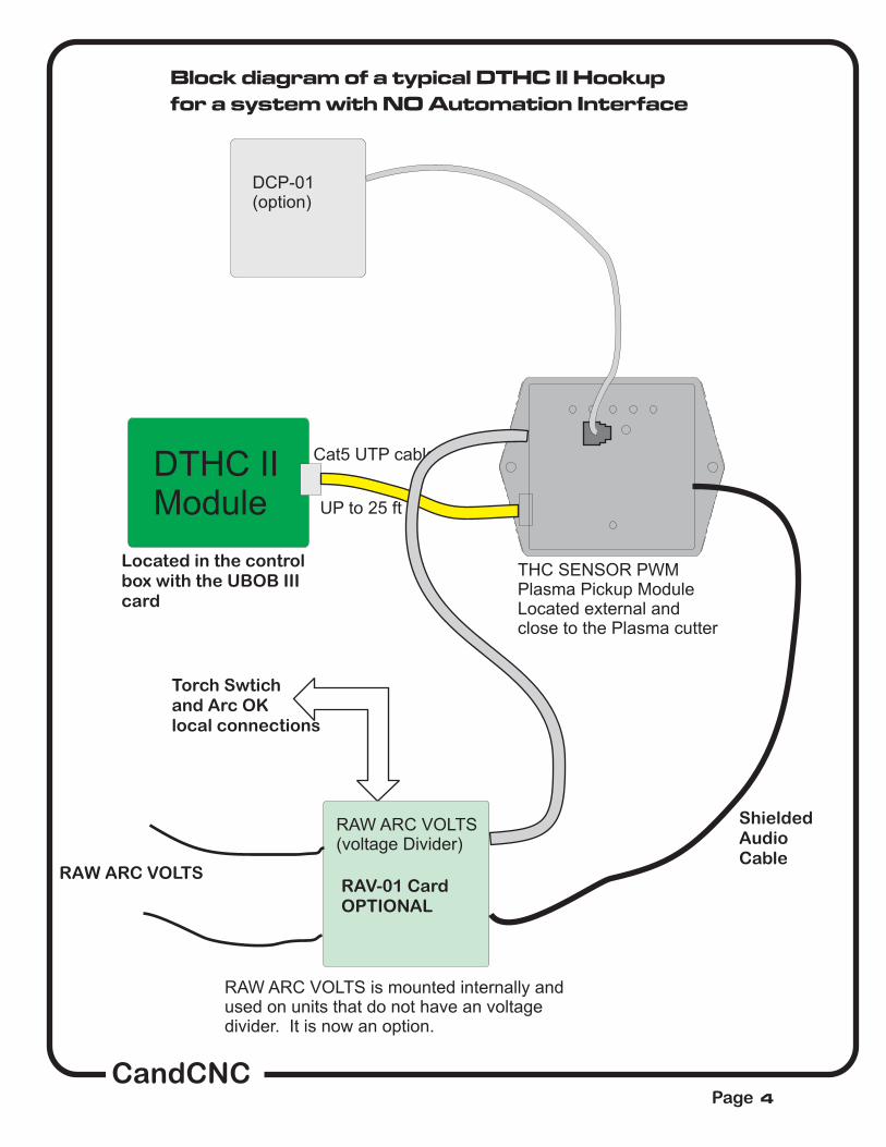
Block diagram of a typical DTHC II Hookup
for a system with NO Automation Interface
Located in the controlbox with the UBOB IIIcard
RAW ARC VOLTS
Torch Swtichand Arc OKlocal connections
for ARC OK
DTHC IIModule
DCP-01(option)
Cat5 UTP cable
UP to 25 ft
RAW ARC VOLTS(voltage Divider)
RAW ARC VOLTS is mounted internally andused on units that do not have an voltagedivider. It is now an option.
THC SENSOR PWMPlasma Pickup ModuleLocated external andclose to the Plasma cutter
ShieldedAudioCable
RAV-01 CardOPTIONAL
CandCNCPage 4

Block diagram of a typical DTHC II Hookup
for a system with full Automation Interface
including Divided Arc Volts)
Located in the controlbox with the UBOB IIIcard
for ARC OK
DTHC IIModule
DCP-01(option)
Cat5 UTP cable
UP to 25 ft
THC SENSOR PWMPlasma Pickup ModuleLocated external andclose to the Plasma cutter
used for ARC CurrentReadout; NOT Required
MIC-01 Custom Cable
CPC Plugom PlasmaUnit
Single cableHookup toPlasma Unit
CandCNCPage 5

CandCNCPage 6
25 ft
CAT5 UTP Cable
16 Pin IDC ribboncable to UBOB III
BASIC DTHC II Module Kit includes:
THC SENSOR PWM DTHC II Expansion
Module

modules setup
dthcii mODULE
thc sensor pwm module
rav-O1 vOLTAGE dIVIDER (option)
CandCNCPage 7

CandCNCPage 8
DTHC II EXPANION MODULE. Locatedabove the UBOB III card in most CandCNCproducts.. Ribbon cable connecting DTHCdown to UBOB card may cover adjustmentpots. If so, gently move it out out the way.Do not unplug the ribbon cable or the cardwill be disabled.
Green Power LEDShould be ON
16 pin header (plug)for DTHC to UBOB
Cable
DTHC Self TestLED
RJ45 connector for cable toTHC SENSOR CARD
2. Using the diagram below and with theTHC SENSOR PWM module in theTEST/CAL mode (LED flashing) adjusttheTorch Volts calibration pot whilewatching the TORCH VOLTS DRO in theMACH screen. Adjust the pot until thevalue displayed is 126 Volts. Note: onlyadjust the setting if it is not displaying 126to 127 volts
TORCH VOLTS Calibration
Unit is calibrated at thefactory.
SET FOR 126VDCINDICATED [TORCH VOLTS]
DCP CalibrationPOT ADJUST perthe instructions

RJ45 Socket for interfaceto THC Sensor PWM Card
Test LED
Test Button
16 PIN HeaderPlug to UBOB
Units are calibratedat the factory.
Actual card layoutmay vary from thephoto.
The photo shows a top view of the DTHC module card. There are two connections tomake. The first is the 16 pin IDC cable between the DTHC and the UBOB FeatureConnector. It’s the only 16 pin header on the UBOB. Both headers are keyed so thecable only fits one way. The other connection is to the DB9 socket from the THCSensor Card.
INSTALLING THE DTHC INTO AN EXISTING MP3000 or BladeRunnerPRODUCT
1. Locate the UBOB III card in the unit. It is the card with the PORT1 and SerialPort inputs. There is a 16 pin FEATURE CONNECTOR. Use the short 16 pin IDCcable included with the DTHC II and plug one end into the FEATURECONNECTOR
2. Mount the DTHC II to the Front Panel using the 4-40 screws and L brackets onthe PCB. Line up the holes for the TEST LED and the TEST BUTTON. Replacethe 4-40 screws through the front into the L Brackets and tighten until the board issnug against the inside of the panel.
3. Hold the back of the DTHC II Module and insert the other end of the 16 pin IDCcable from the UBOB card FEATURE CONNECTOR Header.
4. Proceed to DTHC preliminary testing
DC Power LED
CandCNCPage 9
Skip ths section for products thathave the DTHC II installed at theFacory
PRELIMINARY TESTING THE DTHC MODULE
Further testing requires you have MACH3 installed, the serial cable attached and theMP3000-DHTC profile and screen set loaded. See the section on Loading DTHC DRIVERS
:
If you have an MP3000 with the DTHC II already installed, power up the MP3000-DTHCII andusing a small probe (stiff wire, paperclip, etc push the TEST Button that is recessed behind thefront panel. Press and release one time. The yellow LED should start to flash. If it does notcheck the AC cord (main power) and the 16 pin ribbon cable to the UBOB III card and plug andtry again. There is a green LED on the DTHC II module that will light when the DC to DCconverter is on. There are also three power LED’s on the UBOB card itself that should be on. Ifthe Test LED lights and flashes it indicates that the DTHC II has power and the on-boardprocessor is working. IT DOES NOT TEST ANY OTHER FUNCTION AT THIS POINT.
LOADING DTHC DRIVERS/PLUG-INS
The Following assumes that MACH3 has been installed and that you can start MACH andget a default screen. While the MACH license does not need to be installed to load theCandCNC drivers, you cannot use the THC functions in MACH with a DEMO license. Referto the MP3000 or BladeRunner manual to install a license. . If you are building up a unit(UBOB or UBOB Builders Kit) you need to refer to those manuals for the base setup. If you havealready loaded the CandCNC support files (auto installer from the CD) then you can skip step 1below. The communication drivers need to be configured for DTHC II interface. The followingsteps will take you through setting up the system to use with the DTHC II module.
þ
þ
þ
þ
þ
1. From the Support CD (or a web download locate the MP3000E-DTHC-UBOBIII_INSTALL
file. Run it in Windows with MACH3 NOT RUNNING. It will place two MP3000-DTHC (orBladeRunner) icons on the desktop that will Start MACH with the correct profile instead of havingto use MACH Loader each time, All of the plug-ins , MACH profiles and Icons to use with theDTHC II will be loaded during the install . The MP3000-DTHC profile in MACH will be added alongwith the matching screen sets and macros.
2. After the MP3000-DTHC Install, open MACH3 using either the MP3000-DTHC Icon OR
Bladerunner AIO icon from the matching named profile in the MACH Loader.
3. If you re-install MACH or upgrade, you may need to run the Install again.
4. Open MACH using the MP3000-DTHC-UBOBIII or BladeRunner AIO profile (for the product
you have) and select CONFIG PLUGINS from the CONFIG menu in the top row. You will see alist of plugins that are available At the top of the list are the two CandCNC plug-ins. Each onestarts with “ccc_”
5. Confirm that they are all ENABLED. If you make any changes make sure you close and
restart MACH.
CandCNCPage 10

þUse the screen to select the hardware you are using. The Ubob THC Plugin should
be selected. If you have a ESPII Power supply (part of all BladeRunner, RouterPak andPlazPak products) then be sure to check UACM Modular Power Supply as well. Note the
ê
ê
Activate the recessed TEST Button on the front panel of the MP3000-DTHC or
your unit with the DTHC module installed and connected. The TEST LED shouldstart flashing.The unit goes into a test sequence where the TIP VOLTS DRO is set to100 and the UP screen LED flashes 5 times. Then the TIP VOLTS DRO is set to150 and the DOWN LED flashes 5 times. This test sequence repeats until you hitthe Test Button again and the TEST LED stops flashing.
Make sure you have the right port selected. All Standardcables supplied from CandCNC are straight through with all pins connected(sometimes called “extension cables”
If the test does not show the above results the most probable cause is the
serial communications is not working between the PC and theMP3000/BladeRunner.
For all ESPIIBased Units
DYNAMIC SELF-TEST of DTHC MODULE
CandCNCPage 11
NOTE: If you do nothave this screen thenlook for a Smart KutInstall on your CD andrun that install. It willUpdate your ccc_commplug-in.
1Volts
1
CALInput
THC Sensor PWM
SC
RE
WS
RAW
D1
REV 18
Sw
itch
Torc
h
TO PLASMA
J3
AR
C
K1
TO PLASMA
TEST
+
TORCH RELAYVOLTS
DCP
OK
J2
VR
3
CandCNCTO DTHC
C14
AR
C O
KON
/OF
F
ARC OK
+5
VR
2
TR
IPAR
C O
KR
ELA
Y
U2
11
+12
DCP TEST
RED GRNGRNRED YEL
TEST +5ARCOKTORCH-R +12
1
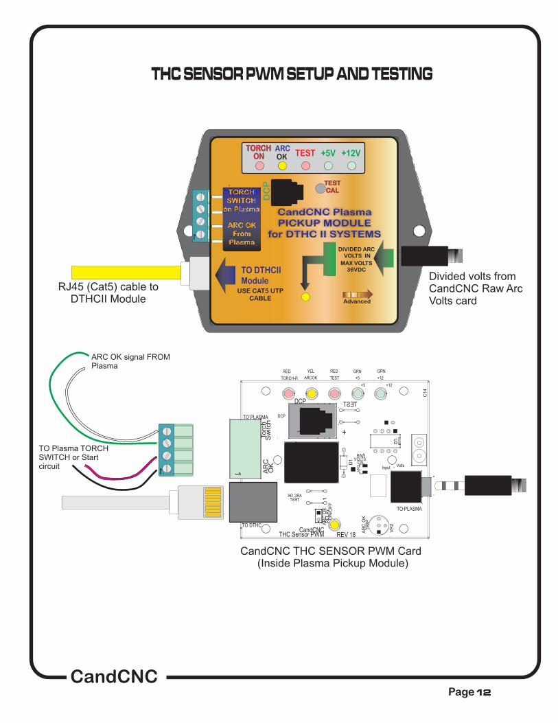
CandCNC THC SENSOR PWM Card(Inside Plasma Pickup Module)
ARC OK signal FROMPlasma
TO Plasma TORCHSWITCH or Startcircuit
THC SENSOR PWM SETUP AND TESTING
1
RJ45 (Cat5) cable toDTHCII Module
Divided volts fromCandCNC Raw ArcVolts card
+12V+5VTEST
TO DTHCIIModule
DIVIDED ARCVOLTS IN
TORCH ARCOKON
DC
P
USE CAT5 UTPCABLE
MAX VOLTS36VDC
Advanced
CandCNC PlasmaPICKUP MODULE
for DTHC II SYSTEMS
TESTCAL
CandCNCPage12

+12V+5VTEST
TO DTHC IIModule
DIVIDED ARCVOLTS IN
TORCH ARCOKON
DC
P
USE CAT5 UTPCABLE
MAX VOLTS36VDC
Advanced
TechnologyPWM
THC SENSOR PWMPlasma Pickup Module
for DTHC IIARC OK
FromPlasma
TORCHSWITCH
on Plasma
CANDCNCModel
remove back cover foraccess to test buttons
ARC VOLTS
+5 +12TESTARCOK
TORCH
THC SENSORUnplugged orDTHC II poweris off
NO ACTIVITYStandby state
TEST/CALMODE. TESTbutton is pushedand released
TORCH FIREDfrom code orscreen button
Arc OK isActive
Arc OK isActive, Torch isfired
Shows condition of power.Both must be ON whenplugged to DTHC II andpower is on
Confirms Torch Relay onTHC SENSOR Card isactive. Tests signal fromDTHC II to fire Torch
Also Used to set sensitivity(trip point of ARC OK fromDCP. for hardware ARCOK from DCP(see Manual)
Shows proper operation ofthe ARC OK from theplasma (or using the DCPas the ARC OK)
Readout on TORCH VOLTS(screen DRO) confirms properoperation of THC SENSORPWM and DTHC LL input
TEST LED FLASHES.Sends PWM signal toDTHC II. Calibrate DTHCII to read 126VDC
Steady RED LED showsanytime Torch RELAY isactive on THC SENSOR
STEADY YEL LED. Turnson if ARC OK from ARCOK TEST button is active
Torch fire is active; ARC OKsignal from Plasma is active
CandCNCPage13
THC SENSOR PWM FRONT PANEL LEDs
CandCNCPage14
CAL
SCREWS
RAW
D1
K1
TO PLASMA
+
TORCH RELAYVOLTS
J2
VR3
C14
TEST
TESTARC OK
11
Volts
Volts
Volts
Volts
50:1
50:1
50:1
50:1
7:1
7:1
7:1
7:1
20:1
20:1
20:1
20:1
SCALE
SCALE
SCALE
SCALE
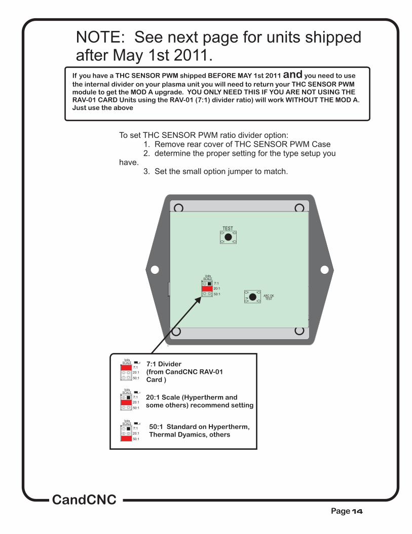
7:1 Divider(from CandCNC RAV-01Card )
20:1 Scale (Hypertherm andsome others) recommend setting
50:1 Standard on Hypertherm,Thermal Dyamics, others
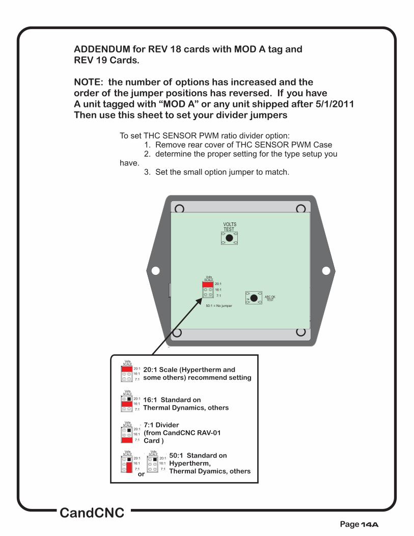
To set THC SENSOR PWM ratio divider option:1. Remove rear cover of THC SENSOR PWM Case2. determine the proper setting for the type setup you
have.3. Set the small option jumper to match.
NOTE: See next page for units shippedafter May 1st 2011.
If you have a THC SENSOR PWM shipped BEFORE MAY 1st 2011 you need to use
the internal divider on your plasma unit you will need to return your THC SENSOR PWMmodule to get the MOD A upgrade. YOU ONLY NEED THIS IF YOU ARE NOT USING THERAV-01 CARD Units using the RAV-01 (7:1) divider ratio) will work WITHOUT THE MOD A.Just use the above
and
CandCNCPage14A
CAL
SCREWS
RAW
D1
K1
TO PLASMA
+
TORCH RELAYVOLTS
J2
VR3
C14
TESTVOLTS
TESTARC OK
11
Volts
Volts
Volts
50:1 = No jumper
20:1
16:1
7:1
SCALE
SCALE
SCALE
7:1 Divider(from CandCNC RAV-01Card )
20:1 Scale (Hypertherm andsome others) recommend setting
50:1 Standard onHypertherm,Thermal Dyamics, others
16:1 Standard onThermal Dynamics, others
To set THC SENSOR PWM ratio divider option:1. Remove rear cover of THC SENSOR PWM Case2. determine the proper setting for the type setup you
have.3. Set the small option jumper to match.
7:1
20:1
16:1
7:1
20:1
16:1
VoltsSCALE
7:1
20:1
16:1
VoltsSCALE
7:1
20:1
16:1
VoltsSCALE
7:1
20:1
16:1
or
ADDENDUM for REV 18 cards with MOD A tag andREV 19 Cards.
NOTE: the number of options has increased and theorder of the jumper positions has reversed. If you haveA unit tagged with “MOD A” or any unit shipped after 5/1/2011Then use this sheet to set your divider jumpers

CandCNCPage 15
1
RJ45 (Cat5) cable toDTHCII Module
Divided volts fromCandCNC Raw ArcVolts card
+12V+5VTEST
TO DTHCIIModule
DIVIDED ARCVOLTS IN
TORCH ARCOKON
DC
P
USE CAT5 UTPCABLE
MAX VOLTS36VDC
Advanced
TechnologyPWM
CandCNC PlasmaPICKUP MODULE
for DTHC II SYSTEMS
Test LEDFlashes in
TEST Mode
THC SENSOR PWM (Plasma Pickup Module) can be put in TEST/CAL modewithout removing the card from the case. Turn the case over and remove the 4corner screw holding the back on and carefully pry off the back panel. It willexpose the back of the PC board and there are two small momentary pushbuttonsand a dual row of option jumpers The switches are small tactile switch thatrequires light pressure. One push puts the unit in test/cal mode. The Test LEDwill flash. The voltage will display on the TORCH VOLTS DRO. A second pushwill take the unit out of test/cal mode and the LED will stop flashing and theTORCH VOLTS reading will return to Zero. Once in TEST mode you can calibratethe DTHC II module to display the correct TORCH VOLTS on the screen. Thecalibration is based on a simulated PWM from the circuit so if the prescale dividersetting is wrong the calibration will show correct but when the torch is fired thevoltage will be wrong. Make sure you match up the prescale option jumper settingwith the divide ratio of the divider ratio your plasma is using.

CandCNCPage16
Volts
1
CALInput
THC Sensor PWM
SCREWS
RAW
D1
REV 18
Switch
Torch
TO PLASMA
J3
ARC
K1
TO PLASMA
+
TORCH RELAYVOLTS
DCP
OK
J2
VR3
CandCNCTO DTHC
C14
ARC OK O
N/OFF
TRIP A
RC OK
RELAY
U2
1
CandCNC THC SENSOR PWM Card
CHECKING ARC OK SIGNAL BACK TO DTHC IICard:
1. Remove case bottom.2 With RJ45 (UTP cable) connected to DTHCIIand unit powered up, depress the ARC OK TESTBUTTON on the card. The ARC OK LED on theMACH screen should light. The ARC OK testLED on the front of the case will light.
Depress and release TESTbutton to test PWM circuitback to DTHC II. Test LEDon front) will flash and DTHCscreen in MACH shoulddisplay a voltage. Calibratedunits (see calibration section)should display 126 to 128volts durning test.
TEST
TESTARC OK
11
Volts
50:1
7:1
20:1
SCALE
Case not shown for clearity
(

THC SENSOR PWM MODULE TESTING
Before you make connections to the plasma unit you may want to do some testingto confirm proper operation of the THC SENSOR PWM with the DTHC II Module.
Set the THC SENSOR PWM Module to the DTHC II module
Connect the THC SENSOR PWM to the RJ45 (CAT5) connector on the DTHC II
Module
Load MACH3 and do the auto-install from the CD for your product (MP3000-
DTHC-UBOB III). Start MACH3 using the Desktop Icon for DTHC Profile
On some products you may have to have the Motor DC on to come out of RESET
Click on the TORCH icon on the screen.
Follow the instructions
for the THC SENSOR PWM section and open the back and use the ARC OK Testbutton.
If any of the tests fail make sure you have the cables firmly attached and that
they are the correct type.
þ and PC.
and makesure you can come out of RESET and that the CP (Charge Pump) LED on the front of theUBOB/MP3000/BladeRunner is ON.
You should see the LED above the
TORCH button on MACH turn on and there will be a click in the THC Sensor PWM cardand the small LED on the front labeled TORCH ON will light. That indicates the TORCHON relay is working.
The next check is to confirm the ARC OK circuit is working.
The ARC OK LED on the MACH3 Screen should light. If it does you canproceed to the actual hookup of the THC SENSOR PWM Module to your plasma unit.
All cards are checked at least twice and most three times before they leave the factory.It’s unusual for a THC SENSOR PWM to be bad or fail in no load testing. If you havechecked all of the connections, cables and MACH setup and you still cannot get the THCSENSOR to work contact us at 903-364-2740 or via e-mail at Tom @CandCNC.com
NOTE: Some Larger (>100A) plasma units or older smaller models use various methodsto start the initial ARC. Most common is HF (HIgh Frequency) start. HF Start presentsseveral challenges. It uses the concept that higher frequency waves travel through air(and arc) easier than DC voltage. The HF is normally combined with a higher voltage andit starts an ARC that the plasma uses to ignite the air. Once the arc fires, if a conductivepart is close, the arc will transfer to the material. The HF start causes a lot of noise andcurrent spikes. The other form of High voltage start is the CD (Capacitor discharge)method. It is basically a high current version of an Automotive ignition system. Up to30,000 volts can be generated. If the THC Sensor is not protected, the high voltage andhigh frequency can cause component failure on the card or (worse) in the THC unit andeven burn the board. The THC Sensor PWM (REV18 and up) is protected from HF andmost High Voltage start circuits.
þ
þ
þ
þ
þ
þ
17
CandCNCPage

Hooking Up Your Plasma Machine to the MP3000-DTHC/BladeRunnerAIO DTHC II
CAUTION: Portions of this install may include opening your plasma cuttermachine and attaching wires.
. Plasma
units have present that can be dangerous or lethal. IFYOU ARE NOT EXPERIENCED WORKING WITH HIGH VOLTAGES, DO NOTATTEMPT TO INSTALL THIS OR ANY OTHER DEVICE INSIDE YOURPLASMA UNIT YOURSELF. SEEK PROFESSIONAL HELP.
In order to control your plasma unit, there are three main connections that needto be made to the plasma unit itself. All of the following operations are to be
done with the
You should determine which type install you will need for your plasma. There is a “decisionflowchart at the end of this manual that can help. It breaks down like this:
There are 3 questions that need to be answered:
1. ) Does your plasma unit have an internal ARC OK (dry contact) signal or one on a standardCPC connector?If not then you will need to purchase and install the Digital Current Probe Option (DCP-01)
2.) Does your plasma unit have an internal voltage divider (Automation Interface) with a ratio of20:1 or 50:1 ?If not you will need to purchase and install the Raw Arc Volts divider card (RAV-01)
3.) Are you using a hand torch or machine torch?If using a hand torch (even with a unit that is setup for automation you will probably need to tapinto the TORCH SWITCH wires from the hand torch to fire the torch remotely (from thecomputer). There is a page on how to do that from either the RAV-01 (if you already have itbecause of #2 above) or directly from the THC SENSOR PWM connector.
If you have a Plasma unit that needs the RAV-01 card you will need to install that card in yourplasma unit of have it done. See the RAV-01 card section for instructions and warnings.If you are using the DCP-01 for ARC OK, there is an addendum at the end of this manaul oninstalling and testing the DCP-01
MAKE SURE THE UNIT IS UNPLUGGED PRIORTO REMOVING ANY COVER(S) OR MAKING ANY CONNECTIONS
HIGH VOLTAGES
power disconnected from your plasma unit
The smaller Hypertherm and other modern brand units use a low noise method called “blowbackarc start”. The electrode is mounted against a spring that keeps it pushed against the inside ofthe Nozzle as long as air is not flowing. When the unit is triggered the starts a few millisecondsafter the current starts to flow in the electrode circuit. As the air flows it pulls the electrode awayfrom the nozzle and creates an ARC. That is used to ionize the air and start the plasma.
The DTHC II can be used with all types of plasma units. The HF units tend to be very noisy andsome even have large amounts of RFI. The total isolation of the DTHC II circuit from any lowlevel (PC logic) including any common ground, stops any conducted noise. The internal circuitsare protected from RFI with proper layout and careful attention to bypass components on allactive circuits.
18
CandCNCPage

1. Most plasma units have connection terminals where wires from the torch orpanel connectors attach to the internal PC Boards. The terminals provide aconvenient place to do your connections. Use crimp-on spade or roundterminals to attach the wires to the terminal strips. Make sure the new wires youinstall do not touch adjacent metal objects. On some machines there may bemore than one set of small wires and are used for sensing tip shorts and otherconditions. use an ohmmeteror continuity checker across each pair while you manually push the torch headbutton. When you identify the pair make note of where they attach. Use #22 to#18 stranded wire (twisted pair) to connect between the two screw terminals onthe THC Sensor PCB marked “Torch Switch” to the two switch terminals in theplasma unit.There is no polarity. NOTE: IF your unit has noise filter chokes from thetorch switch wires up to its internal logic card, it is recommended you placethe two wires to the THC Sensor PCB on the other side of the chokes fromtheir torch head connection (end closest to the internal logic card).
If your unit has a tip voltage connection point (i.e. like the Hypertherm1000 series), you will need to use their manual and suggestions as to howto connect to the two points and run those wires to the THC Sensor card.Just make sure you use wire that has insulation rated for at least 400 V.Small signal wire like telephone wire (UTP) is not rated that high and canarc to nearby components.
a. Note: some machines like the Hypertherm 380 do not have a singleheavy wire to the Torch tip and instead have a set of parallel smallerwires that all terminate into one connector. In the case of the 380 theWHITE wires are the tip volts.
b. You can identify both locations by visually tracing the two leads asthey come into the box. You should find several locations/terminalstrips that have connections to these two points and you can usethose for your sense wire connections. Use unshielded strandedtwisted wire of #22 to #18 ga rated for at least 400V insulation.
To identity the correct pair for the Torch Switch
.
The THC Sensor card is designed to take thefull tip voltage and divide and filter it. Open circuit full tip voltage can beas high as 300VDC in some machines.
If your plasma unit have a designated tip voltagemeasurement point, you will need to locate a place inside the unit whereyou can get one wire onto the workclamp lead and another on the heavylead(s) that connects to the torch tip (electrode).
2
3. does not
CandCNCPage 19

5.
6.
7.
you need not hook
up any ARC OK signals to the RAV-01 card or the THC SENSOR PWM input. The ARCOK signal is derived from the TORCH AMPS (cut current) feedback. ARC OK trip pointis set in the CUT PROFILES in MACH3. See the section on installing and calibratingthe DCP-01/02 on how to set the ARC OK trip point.
, DCP-01 unless you want the added features the DCP-01 can provide(see DCP-01 documentation) Just make the connection to the Arc OK terminals. Someunits provide only relaycontacts; (“dry Contacts”) For that type of signal the ARC OK inputs are J4 and J5 onthe THC Sensor card.
Note: The term Arc Good is interchangeable with Arc Ok , Arc Xfer and OKto MOVE.
NOTE: IT is ESSENTIAL that the of the have a good
earth ground. Refer to the suggested grounding section of the diagrams(#####) and provide for a good earth ground close to the table. A safetyground back to a breaker panel many feet away may be a good ground forAC frequencies (60hz) but poor for higher frequencies like plasma noise.Since we are bypassing any high frequency noise to the plasma chassis, ifit has a poor noise ground it can actually put noise back into the tip voltsrather than shunting it away!
If you are using the CandCNC Digital Current Probe (DCP),
If you have a plasma unit that DOES have an Arc Good signal or you have the
DCP module
chassis plasma unit
c. Make a connection between the locations you have identified thattie directly to the two leads (workclamp and torch tip) to the two “TIPVolta” terminals. Make sure that these wires are routed where theycannot come into contact with hot or moving components. Starting with theREV 14 THC Sensor card the TIP VOLTS inputs have a polarity. The + side
CandCNCPage 20

CandCNCPage 21
NO
YES
Is it a HYPERTHERM45, 65 or 85 models ORTD A60/A80/A120?
Does it have the RearPanel CPC Connector?
Does it have the internalArc Voltage Divider?(Automation Interface PCB)
Does it have an ARC OKsignal.? (aka Arc TransferOK to Move, etc)
Own or Buying aPlasma unitfor CNC ?
BetterGet one!
NO
YES
NO
YES
NO
YES
PurchaseOPTIONDCP-01
Purchase ARC VoltageDivider Card Option
RAVD-01 Card
Purchase AMIC-01CABLE
Purchase AMIC-02CABLE
NO
YES
FINISH
CPC ConnectorInstalled
NO CPC ConnectorInstalled

CandCNCPage
DISCLAIMER AND LEGAL NOTICE
The following section covers the installation of a Voltage Divider card inside the plasma unit.There are dangerous and possibly lethal voltages present in a plasma power supply/unit.ALWAYS UNPLUG THE UNIT FROM THE AC POWER BEFORE REMOVING ANY COVERS.ALWAYS REPLACE ALL COVERS AND SAFETY BARRIERS BEFORE TURNING THEPOWER BACK ON.
You do any install of a card inside of your Plasma Power Unit AT YOUR OWN RISK. If youdo not wish to do the procedure either find a person qualified to do so OR contact us foroptions.
CandCNC/Fourhills Designs (hereafter referred to as “CandCNC”) nor any of itsresellers or agents will be responsible for any damage to any plasma unit or the loss ofany income resulting from using any of our electronics or using our instructions written orverbal to connect to any electronics. While we take care to provide accurate and conciseinformation, we will not be responsible for any damages to equipment, personnel, orsurrounding equipment, structures or land resulting from the direct or indirect use of ourproducts.
The entire liability of CandCNC or any of its agents or employees is to replace orrepair products provided by CandCNC. Under no circumstances will we be liable for anydamages or loss exceeding the value of the actual products provided by us regardless if theproducts are used as described and in the proper manner. All CandCNC products carry awarranty that covers repair or replacement ONLY. Any labor, travel expense or costs toreplace a component or product outside the CandCNC factory is NOT COVERED bywarranty.
If you do not accept the terms of this notice DO NOT OPEN OR INSTALL THERAV-01 CARD. Return the card for a full refund and seek an alternative way to sensethe voltage.
CAUTION: Some plasma units use a very high voltage spark (Capacitor Dischargeor CD) arc starting system. While the RAV-01 card is protected from high voltage inputsCD type systems can cause arcing in the connecting wires or to nearby components.If you have a CD start unit and do not have experience working with high voltage systemsSEEK PROFESSIONAL HELP to do any install.
22

ARCOK
TORCHSWITCH
TO
WO
RK
CL
AM
PC
ON
NE
CT
ION
(+)
TO
EL
EC
TR
OD
EC
ON
NE
CT
ION
(-)
CAUTION: High Voltages PresentWhen TORCH is ON.
CAUTION: High Voltages PresentWhen TORCH is ON.
TO
TH
C S
EN
SO
R P
WM
MO
DU
LE
us
e C
CA
B-3
1
SA
C-0
1 S
hie
ilde
dC
ab
leto
To
rch
Se
nso
r P
WM
Mo
du
le
CandCNC RAW ARC VOLTS Voltage divider card(CASE REMOVED)
Vol
ts
3
Tip Volts
4
+
-
TH
C
J14
2
TP1
TP2
REV 18
J15
HIG
H V
OLT
AG
E
Electrode
D13
C1
Tip
1
SW1
CA
UT
ION
!H
IGH
VO
LTA
GE
L2
- [NEG]
Volts
R1
PLA
SM
A
CA
UT
ION
!
1Can
dCN
C
VOUT
HIG
H V
OLT
AG
E
R6
CA
UT
ION
!
AR
C O
K
OutDivided
+ [POS]Workclamp
CA
UT
ION
TO
TH
C S
EN
SO
R P
WM
TORCH SWITCH
Volts
Div
ided
Volts
ARC OK
1
TO
RC
H S
WIT
CH
1
SW3
PIC
KU
P
-
J5
1
SW2
1
TORCH FIRE
TO
RC
H
+ +
-
WH
EN
TO
RC
H is
ON
FIR
ES
MANUAL 1
Local Connections
1
1
SHIELDED ANALOG CABLE
48” Min
ScotchLOC™
IDC Splices (RED)2 pieces
Part# SAC-01
PART # CCAB-31
RAV to THCSensorPWM Interconnect
48" (min)
RAV-01 Raw Arc Volts CARD
RAV- 01 OPTION KIT
For Plasma Units WITHOUT Internal Voltage Divider
PlexglasInsulatorBase(safety shield)
CandCNCPage 23

ARCOK
TORCHSWITCH
TO
WO
RK
CL
AM
PC
ON
NE
CT
ION
(+)
TO
EL
EC
TR
OD
EC
ON
NE
CT
ION
(-)
CAUTION: High Voltages PresentWhen TORCH is ON.
CAUTION: High Voltages PresentWhen TORCH is ON.
TO
TH
C S
EN
SO
R P
WM
MO
DU
LE
us
e C
CA
B-3
1
SA
C-0
1 S
hie
ilde
dC
ab
leto
To
rch
Se
nso
r P
WM
Mo
du
le
NOTE: PRINTING ON REV 18 PCB
for Torch Switch and Arc OK
are WRONG! Use this diagram
Volts
3
Tip Volts
4
+
-
TH
C
J1
4 2
TP1
TP2
REV 18
J15
HIG
H V
OLTA
GE
Electrode
D13
C1
Tip
1
SW1
CA
UT
ION
!H
IGH
VO
LTA
GE
L2
- [NEG]
Volts
R1
PL
AS
MA
CA
UT
ION
!
1CandC
NC
VOUT
HIG
H V
OLTA
GE
R6
CA
UT
ION
! AR
C O
K
OutDivided
+ [POS]Workclamp
Local Connections
CA
UT
ION
TORCH SWITCH
Volts
Div
ided
Volts
ARC OK
1T
OR
CH
SW
ITC
H1
SW3
PIC
KU
P
-
J5
1
SW2
1
TORCH FIRET
OR
CH
+ +
-
WH
EN
TO
RC
H is O
N
FIR
ES
MANUAL 1T
OT
HC
SE
NS
OR
PW
M
1
1Volts
1
CALInput
Volts
THC Sensor PWM
SC
RE
WS
RAW
D1
REV 18
50
Sw
itch
To
rch
TO PLASMA
J3
AR
C
K1
7
TO PLASMA
TEST
+
20
TORCH RELAYVOLTS
DCP
OK
J2
VR
3
CandCNCTO DTHC
C14
AR
C O
KON
/OF
F
ARC OK
+5
VR
2
TR
IPAR
C O
KR
ELA
Y
U2
11
+12
SCALE
DCP TEST
RED GRNGRNRED YEL
TEST +5ARCOKTORCH-R +12
1
CandCNC RAW ARC VOLTS Voltage divider card
CandCNC THC SENSOR PWM Card
PlexiglasSafetyShield
CandCNCPage 24

+12V+5VTEST
TO DTHC IIModule
DIVIDED ARCVOLTS IN
TORCH ARCOKON
DC
PUSE CAT5 UTP
CABLE
MAX VOLTS36VDC
Advanced
TechnologyPWM
THC SENSOR PWMPlasma Pickup Module
for DTHC IIARC OK
FromPlasma
TORCHSWITCH
on Plasma
CANDCNCModel
remove back cover foraccess to test buttons
ARC VOLTS
CandCNCPage
Divided Volts INFrom internal dividercard
ARC OKINPUT
TORCHSWITCH
25
1Volts
1
CAL
THC Sensor PWM
RAW
D1
REV 18
Sw
itch
Torc
h
TO PLASMA
J3
AR
C
K1
TO PLASMA
TORCH RELAYVOLTS
DCP
OK
J2
VR
3
CandCNCTO DTHC
C14
AR
C O
KON
/OF
F
+5
VR
2
TR
IPAR
C O
KR
ELA
Y
U2
+12
DCP
RED GRNGRNRED YEL
TEST +5ARCOKTORCH-R +12
1

ARCOK
TORCHSWITCH
TO
TH
C S
EN
SO
R P
WM
MO
DU
LE
us
e C
CA
B-3
1
Vol
ts
3
Tip Volts
4
+
-
TH
C
J14
2
TP1
TP2
REV 18
J15
HIG
H V
OLT
AG
E
Electrode
D13
C1
Tip
1
SW1
CA
UT
ION
!H
IGH
VO
LTA
GE
L2
- [NEG]
Volts
R1
PLA
SM
A
CA
UT
ION
!
1Can
dCN
C
VOUT
HIG
H V
OLT
AG
E
R6
CA
UT
ION
!
AR
C O
K
OutDivided
+ [POS]Workclamp
CA
UT
ION
TO
TH
C S
EN
SO
R P
WM
TORCH SWITCH
Volts
Div
ided
Volts
ARC OK
1
TO
RC
H S
WIT
CH
1
SW3
PIC
KU
P
-
J5
1
SW2
1
TORCH FIRE
TO
RC
H
+ +
-
WH
EN
TO
RC
H is
ON
FIR
ES
MANUAL 1
Local Connections
RAV-01 Raw Arc Volts CARD
IF YOU HAVE AN INTERNAL ARC OKSIGNAL: Connect one wire to Terminal4 and Terminal 3 above (left twoterminals)
IF YOU HAVE AN INTERNALARC OK SIGNAL: You will need topurchase a DCP-01 Digital CurrentProbe. It plugs directly into the THCSENSOR PWM Module so the ARC OK
DO NOT
TORCH SWITCH Terminals.If you have a plasma unit with a MachineTorch you will need to locate the two torch fireconnection points. in some units it is calledSTART. IT is a REMOTE Fire set of wires.
IF YOU HAVE A HAND TORCH you will needto identify the two Torch Switch wires thatcome from the Hand torch and tap into themusing the two ScotchLOC connectorsfurnished in the kit
TO
WO
RK
CL
AM
PC
ON
NE
CT
ION
(+)
TO
EL
EC
TR
OD
EC
ON
NE
CT
ION
(-)
CAUTION: High Voltages PresentWhen TORCH is ON.
CAUTION: High Voltages PresentWhen TORCH is ON.
SA
C-0
1 S
hie
ilde
dC
ab
leto
To
rch
Se
nso
r P
WM
Mo
du
le
IMPORTANT: When making any connection inside the PowerMAXdisconnect the unit from the AC Line (unplug it). Do not open thecase with power on the AC line. THERE ARE DANGEROUSVOLTAGES present in the unit anytime it is connected to an ACsource EVEN IF IT IS TURNED OFF.
CandCNCPage 26

Use ScotchLoc IDC Splices (RED) to tie Torch Switch output onTHC Sensor (J10) Screw Terminals. Locate Orange and Violetwires at J10 in the PowerMAX box and tap each wire as shown.To test short two screw terminals on J10 THC Sensor and torchshould fire (Plasma Unit on)
IMPORTANT:
Do not open the case with poweron the AC line.
When making any connection insidethe PowerMAX
THERE ARE DANGEROUSVOLTAGES present in the unit anytime it is connectedto an AC source EVEN IF IT IS TURNED OFF.
disconnect the unit from the ACLine (unplug it).
Connect to Screwterminals J10 1 & 2 onthe THC Sensor Card
FROM HAND TORCH CABLE
CONNECTING HAND TORCH TO THC SENSOR CARD
PAGE 27
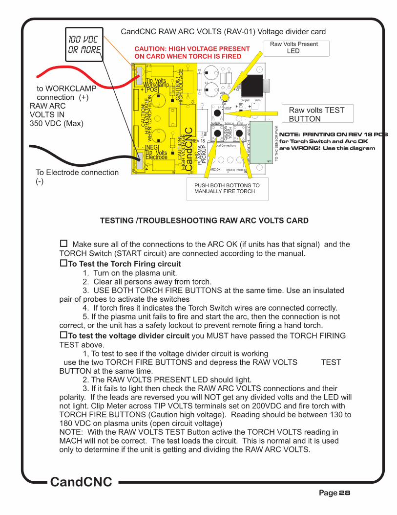
NOTE: PRINTING ON REV 18 PCB
for Torch Switch and Arc OK
are WRONG! Use this diagram
CAUTION: HIGH VOLTAGE PRESENTON CARD WHEN TORCH IS FIRED
CandCNCPage
Volts
Tip Volts
+
-
TH
C
J14
TP1
TP2
REV 18
J15
HIG
H V
OLTA
GE
Electrode
D13
C1
Tip
1
SW1
CA
UT
ION
!H
IGH
VO
LTA
GE
L2
- [NEG]
Volts
R1
PLA
SM
A
CA
UT
ION
!
1Can
dC
NC
VOUT
HIG
H V
OLTA
GE
R6
CA
UT
ION
! AR
C O
K
OutDivided
+ [POS]Workclamp
Local Connections
CA
UT
ION
TO
TH
C S
EN
SO
R P
WM
TORCH SWITCH
Volts
Div
ided
Volts
ARC OK
1
TO
RC
H S
WIT
CH
1
SW3
PIC
KU
P
-
J5
1
SW2
IN
1
TORCH FIRE
TO
RC
H
+ +
-
WH
EN
TO
RC
H is O
N
FIR
ES
MANUAL
1
CandCNC RAW ARC VOLTS (RAV-01) Voltage divider card
PUSH BOTH BOTTONS TOMANUALLY FIRE TORCH
Raw volts TESTBUTTON
Raw Volts Present
LED
TESTING /TROUBLESHOOTING RAW ARC VOLTS CARD
to WORKCLAMPconnection (+)
To Electrode connection(-)
RAW ARCVOLTS IN350 VDC (Max)
o Make sure all of the connections to the ARC OK (if units has that signal) and theTORCH Switch (START circuit) are connected according to the manual.
1. Turn on the plasma unit.2. Clear all persons away from torch.3. USE BOTH TORCH FIRE BUTTONS at the same time. Use an insulated
pair of probes to activate the switches4. If torch fires it indicates the Torch Switch wires are connected correctly.5. If the plasma unit fails to fire and start the arc, then the connection is not
correct, or the unit has a safety lockout to prevent remote firing a hand torch.
you MUST have passed the TORCH FIRINGTEST above.
1, To test to see if the voltage divider circuit is workinguse the two TORCH FIRE BUTTONS and depress the RAW VOLTS TEST
BUTTON at the same time.2. The RAW VOLTS PRESENT LED should light.3. If it fails to light then check the RAW ARC VOLTS connections and their
polarity. If the leads are reversed you will NOT get any divided volts and the LED willnot light. Clip Meter across TIP VOLTS terminals set on 200VDC and fire torch withTORCH FIRE BUTTONS (Caution high voltage). Reading should be between 130 to180 VDC on plasma units (open circuit voltage)NOTE: With the RAW VOLTS TEST Button active the TORCH VOLTS reading inMACH will not be correct. The test loads the circuit. This is normal and it is usedonly to determine if the unit is getting and dividing the RAW ARC VOLTS.
o
o
To Test the Torch Firing circuit
To test the voltage divider circuit
100 VDC
or more
28
CandCNCPage
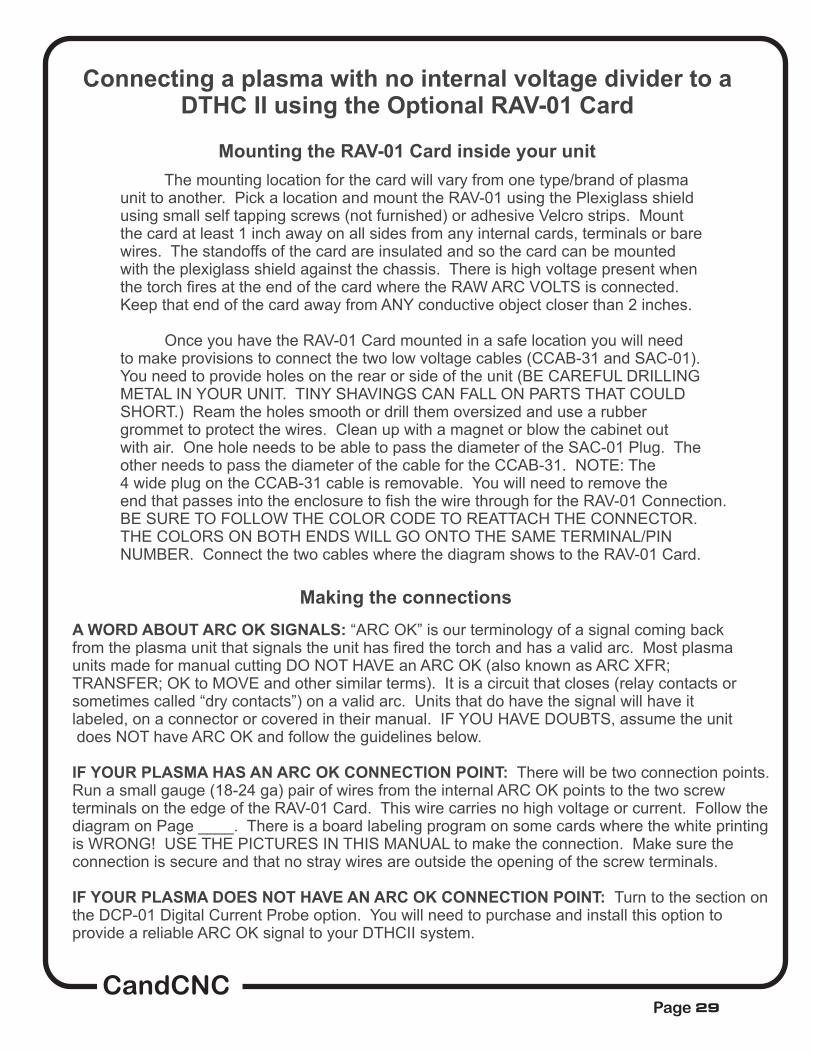
Connecting a plasma with no internal voltage divider to aDTHC II using the Optional RAV-01 Card
Mounting the RAV-01 Card inside your unit
The mounting location for the card will vary from one type/brand of plasmaunit to another. Pick a location and mount the RAV-01 using the Plexiglass shieldusing small self tapping screws (not furnished) or adhesive Velcro strips. Mountthe card at least 1 inch away on all sides from any internal cards, terminals or barewires. The standoffs of the card are insulated and so the card can be mountedwith the plexiglass shield against the chassis. There is high voltage present whenthe torch fires at the end of the card where the RAW ARC VOLTS is connected.Keep that end of the card away from ANY conductive object closer than 2 inches.
Once you have the RAV-01 Card mounted in a safe location you will needto make provisions to connect the two low voltage cables (CCAB-31 and SAC-01).You need to provide holes on the rear or side of the unit (BE CAREFUL DRILLINGMETAL IN YOUR UNIT. TINY SHAVINGS CAN FALL ON PARTS THAT COULDSHORT.) Ream the holes smooth or drill them oversized and use a rubbergrommet to protect the wires. Clean up with a magnet or blow the cabinet outwith air. One hole needs to be able to pass the diameter of the SAC-01 Plug. Theother needs to pass the diameter of the cable for the CCAB-31. NOTE: The4 wide plug on the CCAB-31 cable is removable. You will need to remove theend that passes into the enclosure to fish the wire through for the RAV-01 Connection.BE SURE TO FOLLOW THE COLOR CODE TO REATTACH THE CONNECTOR.THE COLORS ON BOTH ENDS WILL GO ONTO THE SAME TERMINAL/PINNUMBER. Connect the two cables where the diagram shows to the RAV-01 Card.
Making the connections
A WORD ABOUT ARC OK SIGNALS:
IF YOUR PLASMA HAS AN ARC OK CONNECTION POINT:
IF YOUR PLASMA DOES NOT HAVE AN ARC OK CONNECTION POINT:
“ARC OK” is our terminology of a signal coming backfrom the plasma unit that signals the unit has fired the torch and has a valid arc. Most plasmaunits made for manual cutting DO NOT HAVE an ARC OK (also known as ARC XFR;TRANSFER; OK to MOVE and other similar terms). It is a circuit that closes (relay contacts orsometimes called “dry contacts”) on a valid arc. Units that do have the signal will have itlabeled, on a connector or covered in their manual. IF YOU HAVE DOUBTS, assume the unitdoes NOT have ARC OK and follow the guidelines below.
There will be two connection points.Run a small gauge (18-24 ga) pair of wires from the internal ARC OK points to the two screwterminals on the edge of the RAV-01 Card. This wire carries no high voltage or current. Follow thediagram on Page ____. There is a board labeling program on some cards where the white printingis WRONG! USE THE PICTURES IN THIS MANUAL to make the connection. Make sure theconnection is secure and that no stray wires are outside the opening of the screw terminals.
Turn to the section onthe DCP-01 Digital Current Probe option. You will need to purchase and install this option toprovide a reliable ARC OK signal to your DTHCII system.
29
CandCNCPage
Connecting a plasma with no internal voltage to aDTHCII using the Optional RAV-01 CARD
Finding the correct connections.
The first signal you need to identify and locate is the Raw Arc Volts (Raw Tip Volts). This is thevoltage between the Electrode and the Workclamp. The Hypertherm 1000 thru 1650 series havetwo spade terminals (j15 and J16) that are for easy connection of Raw Arc Volts. On latermodels (45/65/85) WITHOUT the internal voltage divider the location of the Raw Arc Volts is notas obvious but they have Field Service Bulletins where they give detailed directions on findingthe Raw Arc Volts. Our manual covers connection to the PowerMax 1000, 1250 and 1650 aswall as the PowerMax 45.
is a search page where you can enter yourmodel number and then search the FSBs. The files are in PDF format.
For other brands of plasma units or a model not designed to be automated the search forconnection points may be a little more difficult but not impossible. The key is the leads going tothe torch cable. On most plasma units you can locate these signals by opening the unit(POWER DISCONNECTED!) and visually tracing the wires coming from the plasma torch. TheWorkclamp will be connected to a stud or terminal inside and is pretty easy to identify. It is thePOSITIVE (+) side of the circuit. The Electrode side goes up the plasma cable to the torch head.It will be one heavy wire or a series of smaller gauge (12ga or larger) stranded wires of the samecolor and they will all connect to the same electrical spot (bus) inside the plasma. In a lot of unitsthese wires are all solid WHITE in color but do not use color as your clue. Some plasmamanufacturers provide block level schematics in their use or service manual that give wire colors(and in some cases terminal numbers and locations).
Using a two conductor wire (18-22 ga) [not supplied] with insulation rated to 400V or more crimpon two ring or fork terminals. USE WIRES OF TWO DIFFERENT COLORS and longenough to reach the RAV-01 Card using an indirect route (give yourself extra wire). Run the firstcolor wire (red or the brightest color) to where the WORKCLAMP attaches. Normally that will bea heavy bus bar with other smaller wires attached. If it is a single large stud you will need a ringterminal that will fit over the stud. That will be your positive (+) wire.
Use the other wire color and run a connection using a ring or fork terminal to where theELECTRODE wires attach.
Carefully route both wires from their connection points over to where they will attach at spadeinputs on the edge of the RAV-01 Card. Keep the wires away from other high voltage wires orcomponents on the circuit board. Use nylon wire ties to secure the wires to other wire bundles orto the chassis. DO NOT WIRE TIE THEM TO COMPONENTS ON THE PC BOARDS. DO NOTUSE LOW VOLTAGE WIRES LIKE THOSE USED FOR WIRING PHONES OF NETWORKS.
The next internal signal you need to locate is the TORCH SWITCH. If you are connecting to aunit with a Hand Torch you will need to find and tap into the two wires coming from the torchswitch in the hand piece. How will you know? First the wires will be smaller and different colors
WHEN YOU HAVE LOCATED THE WORKCLAMP AND ELECTRODE WIRES IN THE UNIT:
https://www.hypertherm.com/Xnet/library.jsp/null
30

That concludes the internal connections you will have to make for your unit.Make sure all leads are insulated and away from possible physical damage.Double check to make sure there are no loose connections and that you haveattached/ re-attached any wires mentioned in the above guidelines.
Replace all covers and safety devices on the plasma unit and plug the plasmaunit into power with the unit switched off. Turn the unit on, and make sure theunit works correctly in manual mode. (i.e. cut a piece of metal by hand). If youhave a machine torch manually fire the torch from the Torch On button in MACH3
CandCNCPage
than the ELECTRODE or PILOT ARC (more about that later) wires. In most cases there will be foursmaller wires. Two will be the torch switch and two will be the PIP or CIP (Consummables-In-Place)wires. Once again the manufacturers documents can be of service here identifying colors and evenconnection points. If you do not have the manufacturers service information with schematics andcannot find them on-line you will need to do a little detective work to identify the torch switch wired.
The first thing your should do is get an Ohmmeter, and with it set to low ohms. Short the leadstogether and make sure the meter shows the change and displays low (close to zero) ohms. If yourmeter has a “squaker” continuity tester position then use that as a tone indication. Clip across two ofthe four smaller wires. If you get no reading or tone (or an OV or OL indication) the circuit is open.Activate the torch switch on the hand piece and if the reading goes to a low value of ohms (<100) orthe tone sounds, it is the switch contacts. Confirm the reading by pushing the torch switch severaltimes. Keep testing wires until you find the pair that changes the meter. Note the colors. Use yourmeter to test the other wires. You may well find a pair that causes the meter to go to low ohms assoon as you touch them, but working the torch switch WILL NOT change the meter. Those are NOTthe torch switch pair. Once you have identified the Torch Switch pair study the diagram on page____ and using the two ScotchLOC connectors slide one over each of
31

1
RJ45 (Cat5) cable toDTHCII Module
Divided volts fromCandCNC Raw ArcVolts card
ARCOK
TORCHSWITCH
TO
TH
CS
EN
SO
RP
WM
MO
DU
LE
us
eC
CA
B-3
1
Vol
ts
3
Tip Volts
4
+
-
TH
C
J14
2
TP1
TP2
REV 18
J15
HIG
H V
OLT
AG
E
Electrode
D13
C1
Tip
1
SW1
CA
UT
ION
!H
IGH
VO
LTA
GE
L2
- [NEG]
Volts
R1
PLA
SM
A
CA
UT
ION
!
1Can
dCN
C
VOUT
HIG
H V
OLT
AG
E
R6
CA
UT
ION
!
AR
C O
K
OutDivided
+ [POS]Workclamp
CA
UT
ION
TO
TH
C S
EN
SO
R P
WM
TORCH SWITCH
Volts
Div
ided
Volts
ARC OK
1
TO
RC
H S
WIT
CH
1
SW3
PIC
KU
P
-
J5
1
SW2
1
TORCH FIRE
TO
RC
H
+ +
-
WH
EN
TO
RC
H is
ON
FIR
ES
MANUAL 1
Local Connections
TO
WO
RK
CL
AM
PC
ON
NE
CT
ION
(+)
TO
EL
EC
TR
OD
EC
ON
NE
CT
ION
(-)
CAUTION: High Voltages PresentWhen TORCH is ON.
CAUTION: High Voltages PresentWhen TORCH is ON.
SA
C-0
1 S
hie
ilde
d C
ab
leto
To
rch
Se
nso
r P
WM
Mo
du
le
CONNECTING TO HAND TORCH SWTICHWIRES FROM RAV-01
sWTICH WIRES FROMPLASMA HAND PIECE
+12V+5VTEST
TO DTHC IIModule
DIVIDED ARCVOLTS IN
TORCH ARCOKON
DC
P
USE CAT5 UTPCABLE
MAX VOLTS36VDC
Advanced
TechnologyPWM
THC SENSOR PWMPlasma Pickup Module
for DTHC IIARC OK
FromPlasma
TORCHSWITCH
on Plasma
CANDCNCModel
remove back cover foraccess to test buttons
ARC VOLTS
ALTERNATE METHOD TO FIRE HAND TORCH IF NOTUSING RAV-01 CARD
CandCNCPage 32
CandCNCPage
AR
CO
KT
OR
CH
SW
ITC
H
TO THC SENSOR PWMMODULE use CCAB-31
Volts
3
TipV olts
4
+-
THC
J14
2
TP1
TP2
REV 18
J15
HIGH VOLTAGE
Electrode
D13
C1
Tip
1
SW1
CAUTION!HIGH VOLTAGE
L2
- [NEG
] Volts
R1
PLASMA
CAUTION!
1
CandCNC
VOU
T
HIGH VOLTAGE
R6
CAUTION!
ARC OK
Out
Divided
+ [POS]
Workclam
p
CAUTION
TO THC SENSOR PWM
TOR
CH
SWITC
H
Volts
Divided
Volts
ARC
OK
1
TORCH SWITCH
1 SW3
PICKUP
-
J5
1
SW2
1
TOR
CH
FIRE
TORCH
++-
WHEN TORCH is ON
FIRES
MAN
UAL
1
Local Connections
TO WORKCLAMPCONNECTION (+)
TO ELECTRODECONNECTION (-)
CA
UT
ION
: Hig
h V
olta
ge
s P
res
en
tW
he
n T
OR
CH
is O
N.
CA
UT
ION
: Hig
h V
olta
ge
s P
res
en
tW
he
n T
OR
CH
is O
N.
SAC-01 Shieilded Cableto Torch Sensor PWM
Module
WH
T
RE
D
YE
L
BL
K
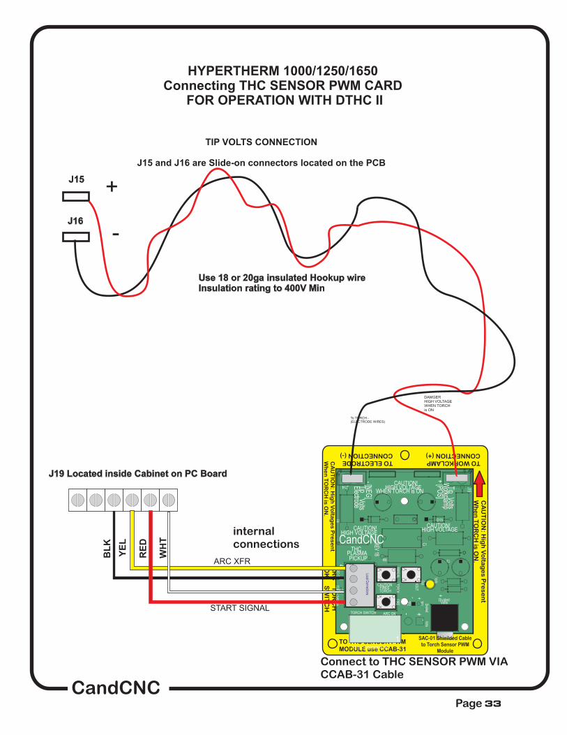
J19 Located inside Cabinet on PC Board
HYPERTHERM 1000/1250/1650Connecting THC SENSOR PWM CARD
FOR OPERATION WITH DTHC II
To TORCH -(ELECTRODE WIRES)
DAMGERHIGH VOLTAGEWHEN TORCHis ON
START SIGNAL
ARC XFR
J15
J16
Use 18 or 20ga insulated Hookup wireInsulation rating to 400V Min
TIP VOLTS CONNECTION
J15 and J16 are Slide-on connectors located on the PCB
+
-
33
Connect to THC SENSOR PWM VIACCAB-31 Cable
internalconnections

CandCNCPage
ARCOK
TORCHSWITCH
TO
TH
C S
EN
SO
R P
WM
MO
DU
LE
us
e C
CA
B-3
1
Vol
ts
3
Tip Volts
4
+
-
TH
C
J14
2
TP1
TP2
REV 18
J15
HIG
H V
OLT
AG
E
Electrode
D13
C1
Tip
1
SW1
CA
UT
ION
!H
IGH
VO
LTA
GE
L2
- [NEG]
Volts
R1
PLA
SM
A
CA
UT
ION
!
1Can
dCN
C
VOUT
HIG
H V
OLT
AG
E
R6
CA
UT
ION
!
AR
C O
K
OutDivided
+ [POS]Workclamp
CA
UT
ION
TO
TH
C S
EN
SO
R P
WM
TORCH SWITCH
Volts
Div
ided
Volts
ARC OK
1
TO
RC
H S
WIT
CH
1
SW3
PIC
KU
P
-
J5
1
SW2
1
TORCH FIRE
TO
RC
H
+ +
-
WH
EN
TO
RC
H is
ON
FIR
ES
MANUAL 1
Local Connections
TO
WO
RK
CL
AM
PC
ON
NE
CT
ION
(+)
TO
EL
EC
TR
OD
EC
ON
NE
CT
ION
(-)
CAUTION: High Voltages PresentWhen TORCH is ON.
CAUTION: High Voltages PresentWhen TORCH is ON.
SA
C-0
1 S
hie
ilde
d C
ab
leto
To
rch
Se
nso
r P
WM
Mo
du
le
HYPERTHERM 1000/1250/1650 andThermal Dynamics units with
rear CPC connector and no Arc VoltageDivider
Use 18 or 20ga insulated Hookup wireInsulation rating to 400V Min
+
-
MIC-02For units with CPC but NOInternal Voltage Divider
1
RJ45 (Cat5) cable toDTHCII Module
Divided volts fromCandCNC Raw ArcVolts card
+12V+5VTEST
TO DTHC IIModule
DIVIDED ARCVOLTS IN
TORCH ARCOKON
DC
P
USE CAT5 UTPCABLE
MAX VOLTS36VDC
Advanced
TechnologyPWM
THC SENSOR PWMPlasma Pickup Module
for DTHC IIARC OK
FromPlasma
TORCHSWITCH
on Plasma
CANDCNCModel
remove back cover foraccess to test buttons
ARC VOLTS
TO CPC CONNECT ON REAROF PLASMA
METHOD TO CONNECT TO UNIT
WITH MACHINE TORCH USING
REAR CPC CONNECTOR FOR
TORCH FIRING AND ARC OK
OPTIONAL RAV-01
MOUNTED INSIDE PLASMA
Route shielded cablethrough rear bulkhead
Raw arc volts connection pointsvary from one model to anotherRefer to manufacturers manualsfor locations
THC SENSOR PWM MODULE
34

TP 19
W
-+ -+
TP 18
RTP 17
B192 VDC 192 VDC
J21(work
lead)
J19 or J18
(white wire)
RAV-01
1 & 2
ScrewTerm 3 & 4
FRONT
To RAV-01 J14NEG input terminal
To RAV-01 Card J15POS input terminal
CAUTION: Make sure wiresand terminals do not touchanything but the screws for
J19 and J21. HIGHVOLTAGE IS PRESENTWHEN TORCH IS ON.
Drawign not to scale
HYPERTHERM PowerMAX 45Connecting THC SENSOR CARD
FOR OPERATION WITH MP3000-DTHC Iand BladeRunner Dragon-Cut series
LOCATION OF J19 and J21Inside PowerMAX 45
CandCNCPage35

THIS SECTION RESERVED FOR POWERMAX 65.85 HOOKUP DATA
CandCNCPage 36
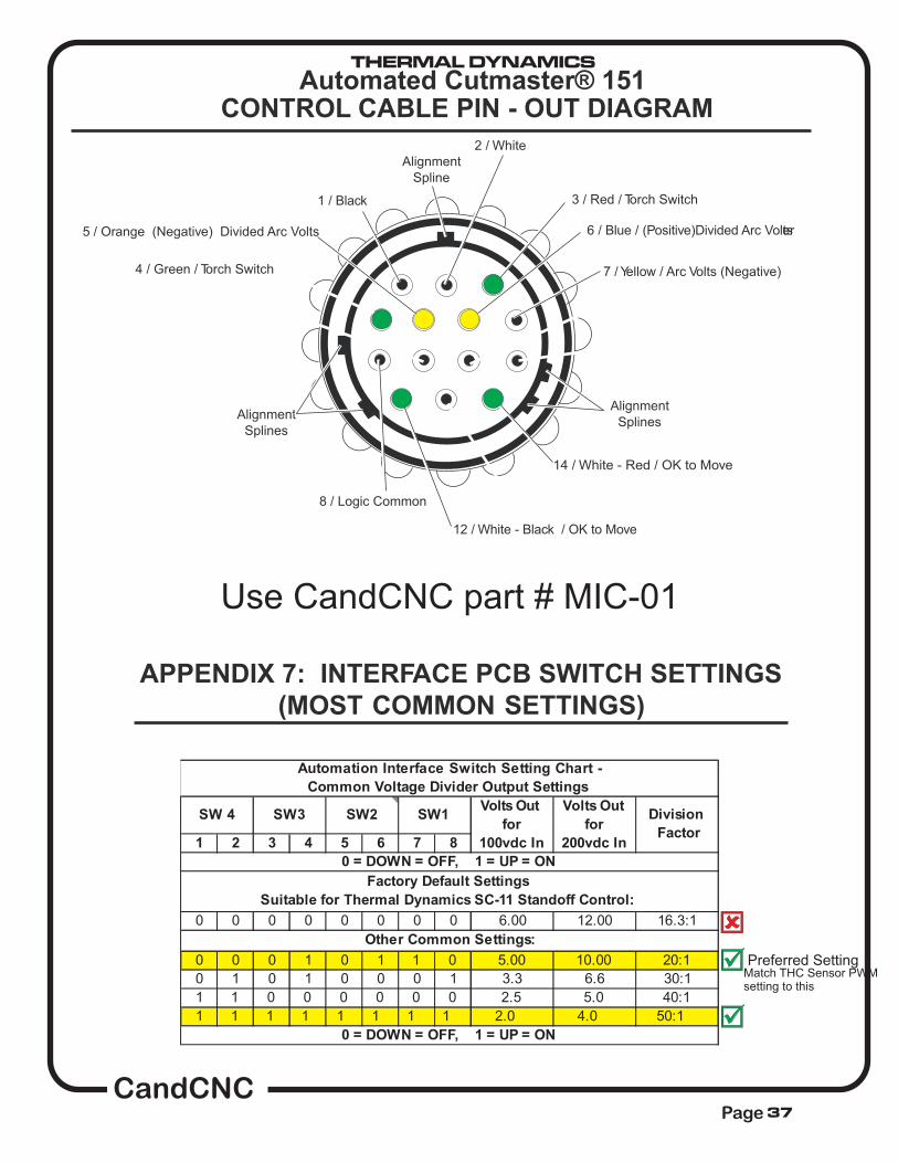
Automated Cutmaster® 151
1 / Black
12 / White - Black / OK to Move
6 / Blue / (Positive)Divided Arc Voltser
7 / Yellow / Arc Volts (Negative)
Alignment
Splines
5 / Orange (Negative) Divided Arc Volts
4 / Green / Torch Switch
8 / Logic Common
Alignment
Splines
2 / White
14 / White - Red / OK to Move
Alignment
Spline
3 / Red / Torch Switch
CONTROL CABLE PIN - OUT DIAGRAM
Use CandCNC part # MIC-01
APPENDIX 7: INTERFACE PCB SWITCH SETTINGS
(MOST COMMON SETTINGS)
1 2 3 4 5 6 7 8
0 0 0 0 0 0 0 0 6.00 12.00 16.3:1
0 0 0 1 0 1 1 0 5.00 10.00 20:1
0 1 0 1 0 0 0 1 3.3 6.6 30:1
1 1 0 0 0 0 0 0 2.5 5.0 40:1
1 1 1 1 1 1 1 1 2.0 4.0 50:1
0 = DOWN = OFF, 1 = UP = ON
Automation Interface Switch Setting Chart -
Common Voltage Divider Output Settings
0 = DOWN = OFF, 1 = UP = ON
SW 4 SW3 SW2 SW1Volts Out
for
100vdc In
Volts Out
for
200vdc In
Division
Factor
Factory Default Settings
Suitable for Thermal Dynamics SC-11 Standoff Control:
Other Common Settings:
Preferred SettingMatch THC Sensor PWMsetting to this
CandCNCPage 37
THERMAL DYNAMICS
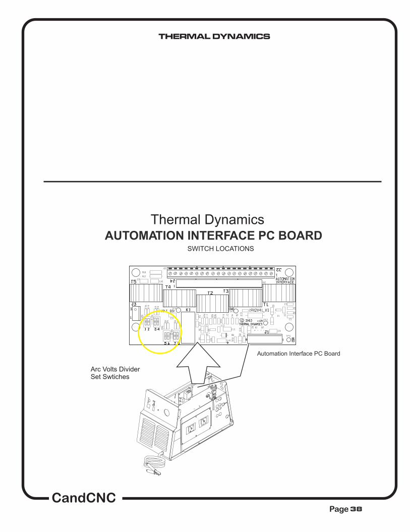
AUTOMATION INTERFACE PC BOARD
Automation Interface PC Board
Arc Volts DividerSet Swtiches
SWITCH LOCATIONS
Thermal Dynamics
CandCNCPage 38
THERMAL DYNAMICS
CandCNCPage
+12VDC
+12VDC
80
PCB4AUTOMATIONINTERFACE PCB
8182
} OK-TO-MOVE
OK-TO-MOVE
83
OK TO MOVE
1TORCH
}
}
E64
E35
78
79
-
+
FULL FEATURED AUTOMATION INTERFACE PCB OPTION
CNC INTERFACE STANDARD ON A40 & A60 UNITS
CNC INTERFACE OPTIONAL ON CM52 & CM82 UNITS
(+)
/PIP
/START
24VAC RETURN
ATC CONNECTOR
24VAC SUPPLY
}
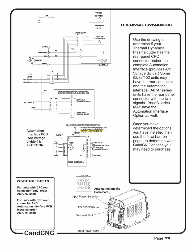
To configure DIVIDED ARC VOLTS signal outputNo jumper installed for ARC VOLTS /16.67Jumper pins 1 & 2 for ARC VOLTS / 50Jumper pins 2 & 3 for ARC VOLTS / 16
K1
To -V OUT 1on PCB1
} /START / STOP
* *
} DIVIDED ARC VOLTS
(5A @250VAC / 30VDC)
/START / STOP
(+)
(-)
(W/ 100K IN SERIES (2))
(-)*
ARC VOLTS
(Sink 50mA @12VDC)
AUTOMATIONTORCH SOLENOID
WORK1WORK1
Q5
PILOT IGBT
Q5
PILOT IGBT
J1J1
12345678
J3J3
1 2 3
P10P10
12345678
J1J1
12345678
TIP1TIP1
J9J9
1234567
P10P10
12345678
WORKWORK
E1E1
J2 PINOUT
13
47
811
1214
L1L1
K1K1
J2J2
234567891011121314
1
-V OUT 1-V OUT 1
TORCH SWITCHTORCH SWITCH
ELECTRODE1ELECTRODE1
J10J10
3
5678
12
4
J2J2
234567891011121314
1
PIP SWITCHPIP SWITCH
12345678
Input Power Cord
Automation Interface
Cable Port
Gas Inlet Port
Filter Assembly
Input Power Selection
Use the drawing todetermine if yourThermal DynamicsPlasma cutter has therear panel CPCconnector and/or thecomplete AutomationInterface (provides ArcVoltage divider) Some52/82/102 units mayhave the rear connectorand the Automationinterface. All “A” seriesunits have the rear panelconnector with the twosignals. Your A seriesMAY have theAutomation InterfaceOption as well.
Once you havedetermined the optionsyou have installed thenuse the flowchart onpage to determine whatCandCNC options youmay need to purchase.
COMPATABLE CABLES:
For units with CPC rearconnector (only) orderAMIC-02 cable
For units with CPC rearconnector ANDAutomation Interface PCBinstalled orderAMIC-01 cable
AutomationInterface PCB(Arc Voltagedivider) isan OPTION
39
THERMAL DYNAMICS

TORCH SETUP
34
1\
13
14
56
Refer to the follwwing table when connecting the Powermax65 or Powermax85 to a DTHC II torch height
controller with a Custom CandCNC Machine Interface Cable
Signal Type Notes Connectorsockets Cable wires
Start
(start
plasma)
Input Normally open.
18 VDC open circuit voltage at
START terminals. Requires dry
contact closure to activate.
3, 4 Green, White
(start
machine
motion)
Output Normally open. Dry contact closure
when the arc transfers. 12, 14 Red, Black
Ground Ground13
Voltagedivider
Output 5 (-), 6 (+) Red (-), White (+)
CandCNC
Shield
ArcTransfer(ARC OK)
Option. Not on all units
Note: Wire colors for CandCNC Hypertherm CPC Interface cables are different from thewire colors for a Hypertherm CPC interface cable
Hypertherm and Powermax are registered trademarks for the Hypertherm INC.
HYPERTHERM
CandCNCPage 40

Divided Arc Volts (neg)
Divided Arc Volts (pos)
HYPERTHERM
�
VOLTAGE DIVIDERBOARD
BLK
RED
BLK
RED
RED
BLK
GRN
WHT
CPCREARCONNECTOR
4
3
14
12
5
6
1
2
3
4
1
2
J21
J33
141157
TORCH
Ele
ctr
ode
Nozzle
WORKCLAMP
CAP
START(on hand torch)
ORGORG
VIOVIO
YEL
WHT
RED
BLUBLU1
2
3
4
5
6
7
8
9
10
J20
J27
34
1\
13
14
56
START
STARTARC OKARC OK
Small headers(pins) on MainControl PCB
ConnectionPoints forHand TorchTorch Switch
HYPERTHERM 45/65/85 Machine InterfaceConnection points
CandCNCPage 41
HYPERTHERM
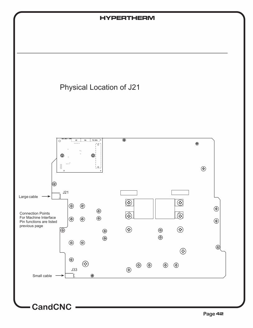
CandCNCPage
Lar e cable
Small cable
gJ21
J33
1
4
1
3
Connection PointsFor Machine InterfacePin functions are listedprevious page
Physical Location of J21
42

HYPERTHERM
CandCNCPage
TORCH SETUP
52 00 :: 11
To change the factory preset voltage divider from 50:1 to the 20:1 setting (recommended):
1. Turn OFF the power supply and disconnect the power cord
2. Remove the power supply cover.
3. Locate the voltage divider DIP switches on the left side of the power supply
Note: The figure below shows the default setting (50:1) with the number 4 switch up
4. Set the DIP switc
SETTING THE 5 POSITION DIP SWITCH FOR USE WITH CandCNC DTHC II TORCH SENSOR PWM
Note: The Hypertherm document has additional swtich settings for other divider ratiosbut ONLY the 20:1 or 50:1 ratios work with the DTHC II and the THC SENSOR PWMmodule. The divider setting inside the THC SENSOR PWM case (bottom removed) ischanged to work with a 20:1, a 50:1 and a 7:1 (CandCNC Raw ARC Volts divider card)input.
Hypertherm and Powermax are registered trademarks for the Hypertherm INC.
43
CandCNCPage
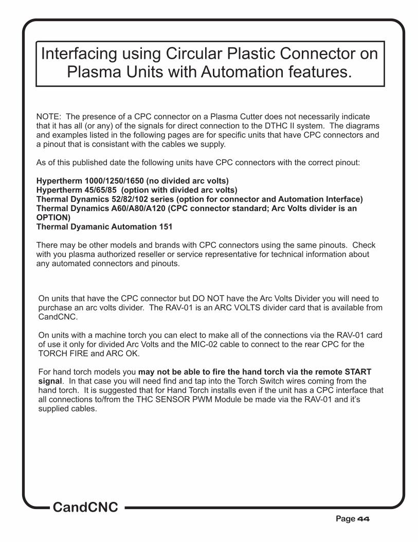
Interfacing using Circular Plastic Connector onPlasma Units with Automation features.
NOTE: The presence of a CPC connector on a Plasma Cutter does not necessarily indicatethat it has all (or any) of the signals for direct connection to the DTHC II system. The diagramsand examples listed in the following pages are for specific units that have CPC connectors anda pinout that is consistant with the cables we supply.
As of this published date the following units have CPC connectors with the correct pinout:
There may be other models and brands with CPC connectors using the same pinouts. Checkwith you plasma authorized reseller or service representative for technical information aboutany automated connectors and pinouts.
Hypertherm 1000/1250/1650 (no divided arc volts)Hypertherm 45/65/85 (option with divided arc volts)Thermal Dynamics 52/82/102 series (option for connector and Automation Interface)Thermal Dynamics A60/A80/A120 (CPC connector standard; Arc Volts divider is anOPTION)Thermal Dyamanic Automation 151
On units that have the CPC connector but DO NOT have the Arc Volts Divider you will need topurchase an arc volts divider. The RAV-01 is an ARC VOLTS divider card that is available fromCandCNC.
On units with a machine torch you can elect to make all of the connections via the RAV-01 cardof use it only for divided Arc Volts and the MIC-02 cable to connect to the rear CPC for theTORCH FIRE and ARC OK.
For hand torch models you. In that case you will need find and tap into the Torch Switch wires coming from the
hand torch. It is suggested that for Hand Torch installs even if the unit has a CPC interface thatall connections to/from the THC SENSOR PWM Module be made via the RAV-01 and it’ssupplied cables.
may not be able to fire the hand torch via the remote STARTsignal
44
CandCNCPage
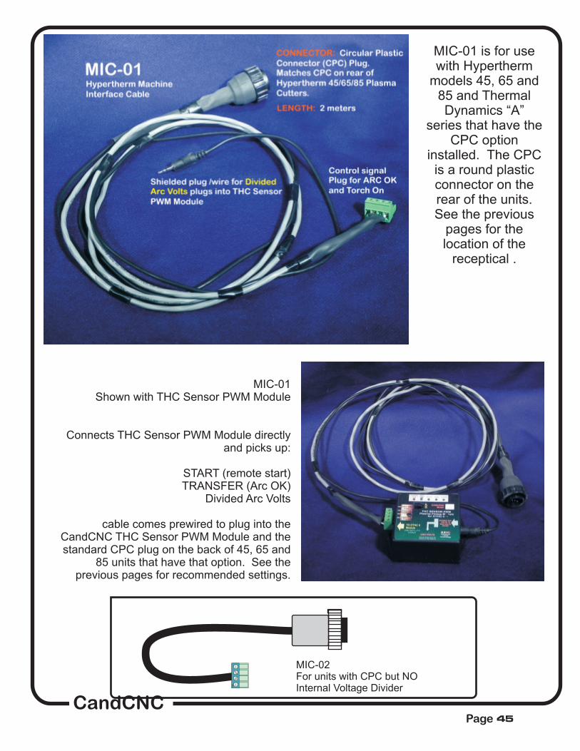
1
MIC-02For units with CPC but NOInternal Voltage Divider
MIC-01Shown with THC Sensor PWM Module
Connects THC Sensor PWM Module directlyand picks up:
START (remote start)TRANSFER (Arc OK)
Divided Arc Volts
cable comes prewired to plug into theCandCNC THC Sensor PWM Module and thestandard CPC plug on the back of 45, 65 and
85 units that have that option. See theprevious pages for recommended settings.
MIC-01 is for usewith Hypertherm
models 45, 65 and85 and ThermalDynamics “A”
series that have theCPC option
installed. The CPCis a round plasticconnector on therear of the units.See the previous
pages for thelocation of the
receptical .
45

setting up and plasma cutting
with the dthc II system
46
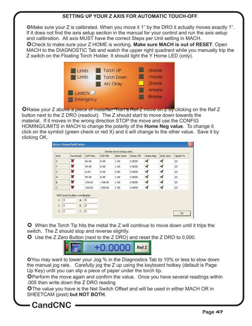
SETTING UP YOUR Z AXIS FOR AUTOMATIC TOUCH-OFF
Make sure MACH is out of RESET
.
Make sure your Z is calibrated. When you move it 1” by the DRO it actually moves exactly 1”.If it does not find the axis setup section in the manual for your control and run the axis setupand calibration. All axis MUST have the correct Steps per Unit setting in MACH.
Check to make sure your Z HOME is working. . OpenMACH to the DIAGNOSTIC Tab and watch the upper right quadrant while you manually trip theZ switch on the Floating Torch Holder. It should light the Y Home LED (only).
µ
µ
µRaise your Z above a piece of material. Run a Ref Z move on Z by clicking on the Ref Zbutton next to the Z DRO (readout). The Z should start to move down towards thematerial. If it moves in the wrong direction STOP the move and use the CONFIGHOMING/LIMITS in MACH to change the polarity of the . To change itclick on the symbol (green check or red X) and it will change to the other value. Save it byclicking OK.
Home Neg value
µ
µ
When the Torch Tip hits the metal the Z will continue to move down until it trips theswitch. The Z should stop and reverse slightly.
Use the Z Zero Button (next to the Z DRO) and reset the Z DRO to 0.000.
You may want to lower your Jog % in the Diagnostics Tab to 10% or less to slow downthe manual jog rate. Carefully jog the Z up using the keyboard hotkey (default is PageUp Key) until you can slip a piece of paper under the torch tip.
Perform the move again and confirm the value. Once you have several readings within.005 then write down the Z DRO reading
The value you have is the Net Switch Offset and will be used in either MACH OR inSHEETCAM (post) .
µ
µ
µ
but NOT BOTH
CandCNCPage 47

We have provided special Posts for MACH3 and the MP3000-THC to be used whengenerating output from SheetCAM. It has an automatic “touch-n-go” feature that reads thetraveled distance and once it exceeds 500mm (about 20 inches) a Z reference isperformed .This post is intended for use with the MP1000-THC and MP3000-DTHC and a floatinghead setup ONLY.
If you are using SheetCAM you need to open the specific posts (or posts) you use with atext editor (Notepad, etc) and find the line in the post that sets the value of theSwitchOffset. It will look something like this:
dist = 9999999refdistance = 10* scale
--Put your switch offset value hereswitchoffset =.052lastz = 0
The value needs to be set to the number you wrote down when you did thetests on the previous page (
b.Mach 3 provides added THC functionality and has inputs for pierce height, initial cut
height , etc. At this point we have not tested those features so their use isdiscouraged. It is recommend that any references for the Z while cutting be edited into theg-code as:
G28.1 Z.5G92 Z0G00 Z[your switch travel here in decimal]G92 Z0G00 Z.5
This should be inserted just prior to the Torch ON (M03) event at any given pierce pointwhere you wish to re-reference the Z
Note to SHEETCAM (and SheetCAM TNG) users.
The latest versions of SheetCAM TNG ship with several MP1000
named posts. They will work with of our THC products (MP1000, MP3000, DTHC,LCTHC, etc)
switchoffset
For non-SHEETCAM users.
G00 Z.75
just prior to the next pierce
all
SETTING UP YOUR Z AXIS FOR AUTOMATIC TOUCH-OFF).
refdistance
Make sure you save the file with the .post or the .scpost file extension it had to start with.
is the distance you let XY travel before you do the next touch-off sequence.You can change how close (and how often) that sequence happens by raising or loweringthe value. Scale in this context is 25.4. Refdistance in in mm so in the example above theactual distance is 254 mm (about 10 inches). That is the combined distance of both X & Ymovement. On thin material that may need a touch off before every pierce that the numberto 0. Save the POST with another name and select it when doing your final CAM post toG-code.
CandCNCPage 48
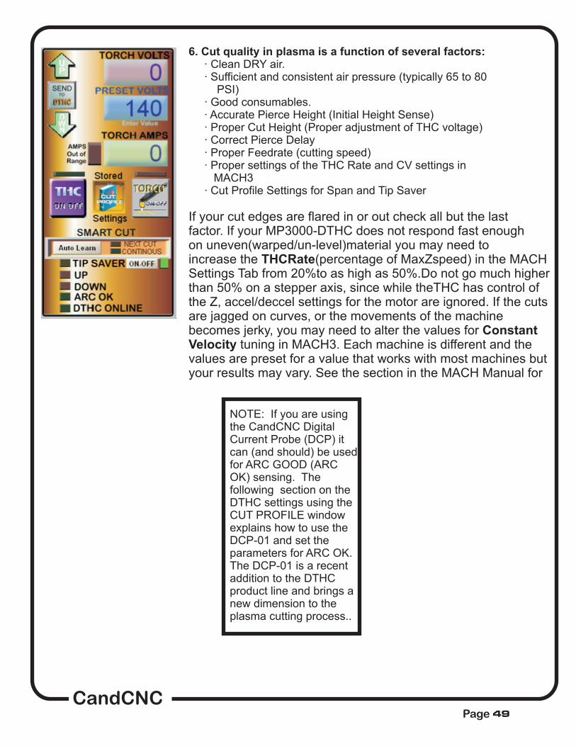
6. Cut quality in plasma is a function of several factors:· Clean DRY air.· Sufficient and consistent air pressure (typically 65 to 80
PSI)· Good consumables.· Accurate Pierce Height (Initial Height Sense)· Proper Cut Height (Proper adjustment of THC voltage)· Correct Pierce Delay· Proper Feedrate (cutting speed)· Proper settings of the THC Rate and CV settings in
MACH3· Cut Profile Settings for Span and Tip Saver
If your cut edges are flared in or out check all but the lastfactor. If your MP3000-DTHC does not respond fast enoughon uneven(warped/un-level)material you may need toincrease the (percentage of MaxZspeed) in the MACHSettings Tab from 20%to as high as 50%.Do not go much higherthan 50% on a stepper axis, since while theTHC has control ofthe Z, accel/deccel settings for the motor are ignored. If the cutsare jagged on curves, or the movements of the machinebecomes jerky, you may need to alter the values for
tuning in MACH3. Each machine is different and thevalues are preset for a value that works with most machines butyour results may vary. See the section in the MACH Manual for
THCRate
ConstantVelocity
NOTE: If you are usingthe CandCNC DigitalCurrent Probe (DCP) itcan (and should) be usedfor ARC GOOD (ARCOK) sensing. Thefollowing section on theDTHC settings using theCUT PROFILE windowexplains how to use theDCP-01 and set theparameters for ARC OK.The DCP-01 is a recentaddition to the DTHCproduct line and brings anew dimension to theplasma cutting process..
CandCNCPage 49

TORCH HEIGHT CONTROL section
THC ON/OFF BUTTON:
The TORCH ON/OFF
The TIP SAVER LED
The THC functions in MACH are controlled by the THCON/OFF button on the screen. If The LED above the THC ON/OFF button is greyedout (off) then the THC inputs to MACH are ignored. It also turns off the “Hold for ArcOK” function in MACH so that you can have XYZ motion without getting an ARC OKfrom the THC Sensor Card (at the plasma unit) If you have the Auto THC ON boxchecked (in the Cut Profiles Popup) the THC will automatically activate when the RUNbutton is pressed to run G-code. There may be times you wan to run without THC orto tune the THC logic in MACH ON/OFF while cutting. You can use the THC button todo that.
button controls turning the Torch on/off. Under normal cuttingcondiitons (e.g. running from code) the Torch ON/OFF is controlled from the software.You have the option of turning the torch on or off manually using the button. The Torchbutton will fire the torch anytime MACH is out of RESET. The TORCH LED above thebutton shows the status of the Torch output. When it is illuminated the signal is beingsent to the Mp3000 to turn on the torch. Anytime the Torch is on (or should be on)through manual OR software activation that LED should will be on.
is a indicator to let the operator know that the DTHC TIP SAVERcircuit has activated and has locked the Z down movement. The parameters used forthe Tip Saver are set in the DTHC Cut Profiles Popup window. The settings andoperation of the DTHC is covered the DTHC Operation and Setup and the CUTPROFILES part of the manual. NOTE:It is normal for the TIP SAVER to go active at the end of a cut where you wouldnormally get a head dive or as it’s cutting if it cuts across or very close to an existingcut. If the torch preset value is wrong for the type material and tip you are using thenthe TIP SAVER may come on and stay on. Check your settings if this occurs.
MP3000-DTHC Screen Section The following pages cover the operation andscreens involved with the CUT PROFILES
and the DTHC section of the screen.
NOTE: The DTHC is usedin all of our Plug-n-Runproducts including theMP3000, BladeRunnerDragon-Cut, and theUBOB Builders Kit +DTHC. If the text refers toone of the specificproducts then take that tomean the same as “any
CandCNCPage 50
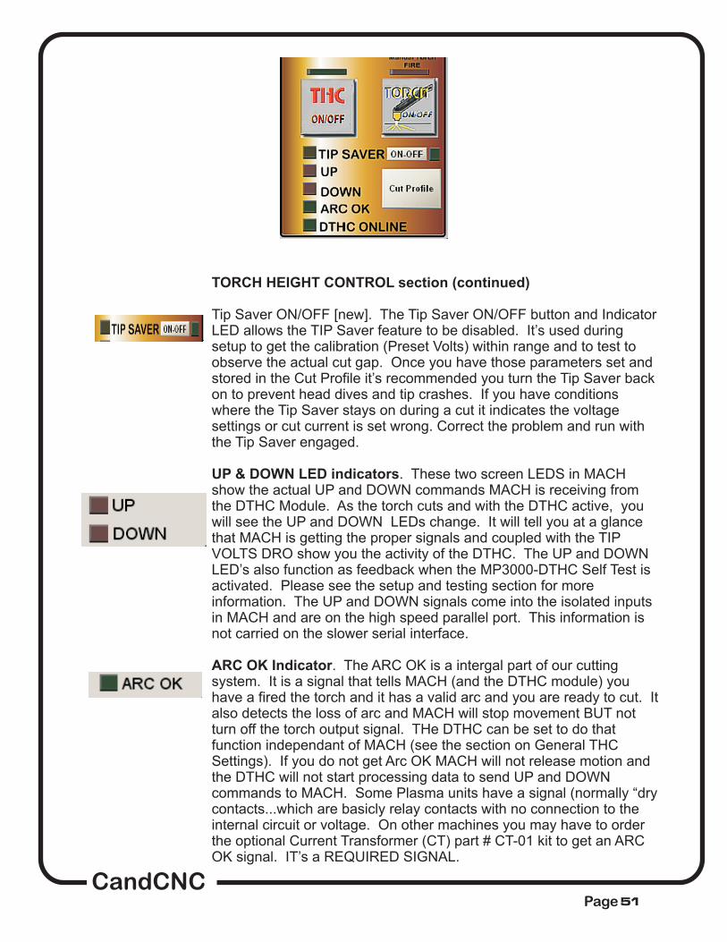
TORCH HEIGHT CONTROL section (continued)
UP & DOWN LED indicators
ARC OK Indicator
Tip Saver ON/OFF [new]. The Tip Saver ON/OFF button and IndicatorLED allows the TIP Saver feature to be disabled. It’s used duringsetup to get the calibration (Preset Volts) within range and to test toobserve the actual cut gap. Once you have those parameters set andstored in the Cut Profile it’s recommended you turn the Tip Saver backon to prevent head dives and tip crashes. If you have conditionswhere the Tip Saver stays on during a cut it indicates the voltagesettings or cut current is set wrong. Correct the problem and run withthe Tip Saver engaged.
. These two screen LEDS in MACHshow the actual UP and DOWN commands MACH is receiving fromthe DTHC Module. As the torch cuts and with the DTHC active, youwill see the UP and DOWN LEDs change. It will tell you at a glancethat MACH is getting the proper signals and coupled with the TIPVOLTS DRO show you the activity of the DTHC. The UP and DOWNLED’s also function as feedback when the MP3000-DTHC Self Test isactivated. Please see the setup and testing section for moreinformation. The UP and DOWN signals come into the isolated inputsin MACH and are on the high speed parallel port. This information isnot carried on the slower serial interface.
. The ARC OK is a intergal part of our cuttingsystem. It is a signal that tells MACH (and the DTHC module) youhave a fired the torch and it has a valid arc and you are ready to cut. Italso detects the loss of arc and MACH will stop movement BUT notturn off the torch output signal. THe DTHC can be set to do thatfunction independant of MACH (see the section on General THCSettings). If you do not get Arc OK MACH will not release motion andthe DTHC will not start processing data to send UP and DOWNcommands to MACH. Some Plasma units have a signal (normally “drycontacts...which are basicly relay contacts with no connection to theinternal circuit or voltage. On other machines you may have to orderthe optional Current Transformer (CT) part # CT-01 kit to get an ARCOK signal. IT’s a REQUIRED SIGNAL.
CandCNCPage 51
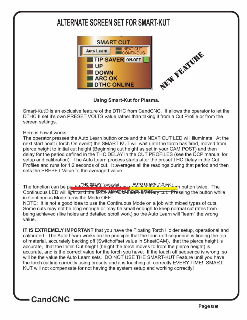
ALTERNATE SCREEN SET FOR SMART-KUT
Using Smart-Kut for Plasma.
IT IS EXTREMELY IMPORTANT
Smart-Kut® is an exclusive feature of the DTHC from CandCNC. It allows the operator to let theDTHC II set it’s own PRESET VOLTS value rather than taking it from a Cut Profile or from thescreen settings.
Here is how it works:The operator presses the Auto Learn button once and the NEXT CUT LED will illuminate. At thenext start point (Torch On event) the SMART KUT will wait until the torch has fired, moved frompierce height to Initial cut height (Beginning cut height as set in your CAM POST) and thendelay for the period defined in the THC DELAY in the CUT PROFILES (see the DCP manual forsetup and calibration). The Auto Learn process starts after the preset THC Delay in the CutProfiles and runs for 1.2 seconds of cut. It averages all the readings during that period and thensets the PRESET Value to the averaged value.
The function can be put into continuous mode by pressing the Auto Learn button twice. TheContinuous LED will light and the torch will Auto Learn on every cut. Pressing the button whilein Continuous Mode turns the Mode OFF.NOTE: It is not a good idea to use the Continuous Mode on a job with mixed types of cuts.Some cuts may not be long enough or may be small enough to keep normal cut rates frombeing achieved (like holes and detailed scroll work) so the Auto Learn will “learn” the wrongvalue.
that you have the Floating Torch Holder setup, operational andcalibrated. The Auto Learn works on the principle that the touch-off sequence is finding the topof material, accurately backing off (Switchoffset value in SheetCAM), that the pierce height isaccurate, that the Initial Cut height (height the torch moves to from the pierce height) isaccurate, and is the correct value for the torch you have. If the touch off sequence is wrong, sowill be the value the Auto Learn sets. DO NOT USE THE SMART-KUT Feature until you havethe torch cutting correctly using presets and it is touching off correctly EVERY TIME! SMARTKUT will not compensate for not having the system setup and working correctly!
THC DELAY (variable) AUTO LEARN (1.2 sec)
TOTAL SMART-KUT CYCLE TIME
NEW F
EATURE
CandCNCPage 52

MP 3000 CONTROL SECTION
The MP3000 Control provides controls to change the cut parameters forthe DTHC. It allows the operator to set and change values before andwhile cutting.
The UP arrow increases the PRESET VOLTS byone full volt per click in essence raising the torch and increasing the gap.It increments the PRESET VOLTS DRO and
. This can be useful since you can change thePRESET VOLTS while cutting which will adjust the CUT GAP at theTORCH. Sometimes a volt ot two of “tweek” can improve the cut. At theend of the cut the Current Settings will remain (for the next cut) and theybecome the new “Current Settings” in the memory of the DTHC so if thesystem is shutdown, the next time it comes up, the values will be the newsetting. See the section on using the Cut Profiles button.
Performs the same function as the UP ARROWbut decrements the PRESET VOLTS DRO (value). It has the same effectas lowering the torch and decreasing the Tip Volts.
This button is provided in the event you entera value directly into the PRESET VOLTS DRO and then need to updatethe current settings with that value. To enter a value into a DRO you mustselect the DRO (backgound color will change), Type in the new value andhit ENTER on the keyboard. If you fail to hit ENTER the value will not“stick” and reverts back to the previous value. Do not use the direct DROinput while cutting! It made to change the value by a large amount likewhen you change tip sizes or go to Fine Cut Consummables. Normally afew volts is all you need to adjust to make a big difference in the cut gap.
Shows the actual volts at the Torch Tip. It willchange as the Torch cuts but with the DTHC engaged (and the THCbutton in MACH3 Active) it should track closely the PRESET VOLTSprovided the TIP SAVER or THC FAULT has not been tripped
UP ARROW Button:
automatically sends thevalue to the DTHC
DOWN ARROW Button:
SEND to MP3000 Button:
TORCH VOLTS DRO
CandCNCPage 53
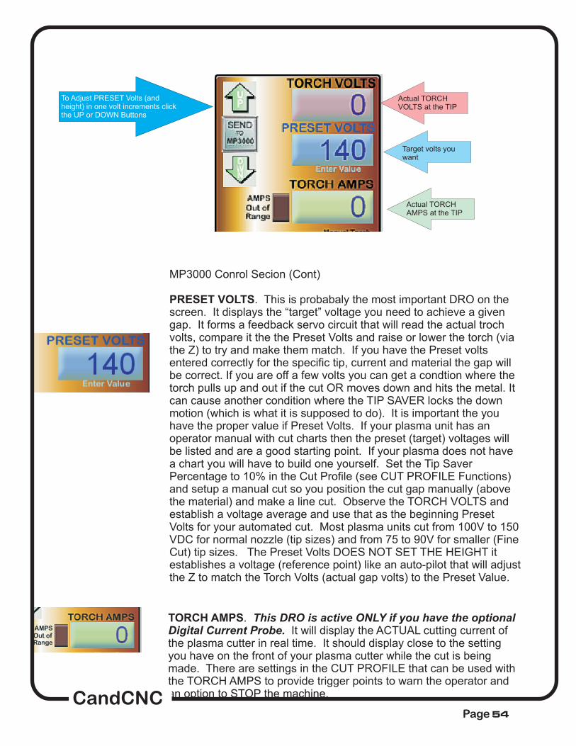
MP3000 Conrol Secion (Cont)
. This is probabaly the most important DRO on thescreen. It displays the “target” voltage you need to achieve a givengap. It forms a feedback servo circuit that will read the actual trochvolts, compare it the the Preset Volts and raise or lower the torch (viathe Z) to try and make them match. If you have the Preset voltsentered correctly for the specific tip, current and material the gap willbe correct. If you are off a few volts you can get a condtion where thetorch pulls up and out if the cut OR moves down and hits the metal. Itcan cause another condition where the TIP SAVER locks the downmotion (which is what it is supposed to do). It is important the youhave the proper value if Preset Volts. If your plasma unit has anoperator manual with cut charts then the preset (target) voltages willbe listed and are a good starting point. If your plasma does not havea chart you will have to build one yourself. Set the Tip SaverPercentage to 10% in the Cut Profile (see CUT PROFILE Functions)and setup a manual cut so you position the cut gap manually (abovethe material) and make a line cut. Observe the TORCH VOLTS andestablish a voltage average and use that as the beginning PresetVolts for your automated cut. Most plasma units cut from 100V to 150VDC for normal nozzle (tip sizes) and from 75 to 90V for smaller (FineCut) tip sizes. The Preset Volts DOES NOT SET THE HEIGHT itestablishes a voltage (reference point) like an auto-pilot that will adjustthe Z to match the Torch Volts (actual gap volts) to the Preset Value.
PRESET VOLTS
TORCH AMPS.It will display the ACTUAL cutting current of
the plasma cutter in real time. It should display close to the settingyou have on the front of your plasma cutter while the cut is beingmade. There are settings in the CUT PROFILE that can be used withthe TORCH AMPS to provide trigger points to warn the operator andan option to STOP the machine.
This DRO is active ONLY if you have the optionalDigital Current Probe.
To Adjust PRESET Volts (andheight) in one volt increments clickthe UP or DOWN Buttons
Actual TORCHVOLTS at the TIP
Actual TORCHAMPS at the TIP
Target volts youwant
CandCNCPage 54
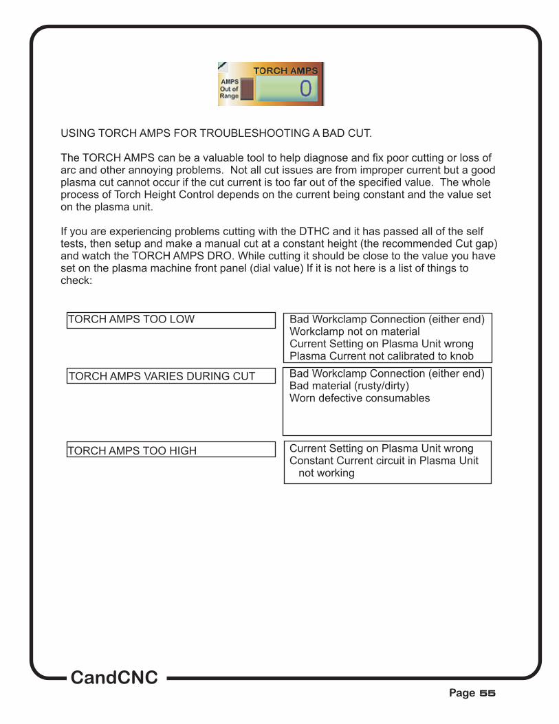
USING TORCH AMPS FOR TROUBLESHOOTING A BAD CUT.
The TORCH AMPS can be a valuable tool to help diagnose and fix poor cutting or loss ofarc and other annoying problems. Not all cut issues are from improper current but a goodplasma cut cannot occur if the cut current is too far out of the specified value. The wholeprocess of Torch Height Control depends on the current being constant and the value seton the plasma unit.
If you are experiencing problems cutting with the DTHC and it has passed all of the selftests, then setup and make a manual cut at a constant height (the recommended Cut gap)and watch the TORCH AMPS DRO. While cutting it should be close to the value you haveset on the plasma machine front panel (dial value) If it is not here is a list of things tocheck:
TORCH AMPS TOO LOW
TORCH AMPS VARIES DURING CUT
TORCH AMPS TOO HIGH
Bad Workclamp Connection (either end)Workclamp not on materialCurrent Setting on Plasma Unit wrongPlasma Current not calibrated to knob
Bad Workclamp Connection (either end)Bad material (rusty/dirty)Worn defective consumables
Current Setting on Plasma Unit wrongConstant Current circuit in Plasma Unit
not working
CandCNCPage 55

CURRENT SETTINGS BUTTON:
OK
Cancel
Shows the current profile and settings being used by the DTHC. The DTHCuses a real time processor to process the torch volts and send the proper signals to MACH. The processorstores the settings in NVRAM (non-volatile ram) Changing any setting in the Settings Group or the GeneralTHC Settings and using (closes the window) saves the profile (writes it to the DTHC processor RAM. Youmust close the window to be able to access the MACH screen and to move the machine (JOG) or RUN g-code. cancels any changes you have made before you exit
The DTHC module “remembers” the settings you used last even if you power everything off. The Cut Profilevalues are sent to the DTHC module (via a serial connection from the PC to the UBOB and up to the DTHCmodule) The “Current Values are what is in the DTHC memory. Values are transferred when you hit OK NOTwhen they are just displayed. ONLY the CURRENT SETTINGS values are what the DTHC uses duringcutting. If you pull up a profile and do not transfer it to the DTHC module
PROFILE LIST BOX :Add button
. Delete Button
Shows a list of all saved profiles. Any profile can be selected and those parameterswill be transferred to the Current Settings screen. You can Add new Profiles using the . Todelete an entire profile highlight the profile by clicking on it and hit the . If for any reason theDTHC module has lost communication with MACH the settings on the screen ARE NOT SAVED to theNVRAM and opening the screen again to display CURRENT SETTINGS will show the old settings. Checkto make sure the THC ONLINE LED is on.
CandCNCPage 56

Adding Profiles
If your plasma machine has nodocumentation or recommended cut charts then go to the Plasma Setupsection in this manual and use the Initial setup and calibration methods toestablish a base line for building your own charts.
. As you do cutting on your table using the DTHC Digital TorchHeight Control you will be able to choose optimized settings for each type ofcutting you do. You can edit and save an existing Cut Profile or ADD a new oneof you own. Since there are variables that change from one machine toanother the sample values may or may not be usable in your environment. It’sbest to start out with the default Settings and use the Tip Volt Presetrecommended by your plasma manufacturer.
The two most criticalcomponents are the feedrate (set in the G-Code and CAM program) and the TipVolt Preset. Since both values vary between machines it’s best to run a seriesof tests. Even the cut gap (distance from the tip to the material) and the gapvolts (actual tip volts) varies from one plasma manufacturer to another.
Other machines will vary. It’s best to develop your ownvalues for your machine over time and store them in the Cut Profiles. NOTE:The Cut Profiles are stored in a flat file named THC_Profiles.txt located in themain MACH3 folder.
Example: A Hypertherm G series calls for .063 (1/16 ) cut gap and a tip voltsreading of 140VDC on 10Ga material with a 40A tip. A Thermal Dynamics unituses a wider cut gap (about .1 to .12) and lower tip volts (about 110VDC) forthe same material.
It’s a good idea to back up your MACH settings (XMLfiles), Screens (SET Files) and the Cut Profile listed. Restoring values from abackup copy can save hours or frustration.
CandCNCPage 57

INFORMATION GROUP:
PROFILE NAME
MATERIAL:
FEEDRATE:does not set the actual feedrate the file runs at.
TIP SIZE:
The Information section at the top of the window is for storing informationthat you can refer to. It saves time by having the vital cut parametersinstantly available to the operator
It is there to use as a reference in place of having to go to theUser Manual and Cut Charts to get the numbers
: The Profile Name is important because that isthe name that shows up in the Profile List Box. Use names that will helpyou find the right profile quickly.
Allows you to list material detail. It helps the operatorconfirm that the setting matches the material being cut.
The recommended Feed Rate, This is informationalfor reference only andIt gives the operator a value to confirm when the job runs. Feedrates areset in g-code (from the CAM program). The operator can use theFeedrate Override controls on the Program Run Screen to adjust thefeedrate.
Memo field to remind the operator what size tip (nozzle)to use for cutting. Typically tips are rated in “AMPS” with common sizesbeing 25, 30, 40, 60, 80 and larger on bigger plasma cutters. The orificesize is the primary difference between tips. The smaller the orifice thelower the current rating. Smaller tips cut with a smaller kerf width and atlower feedrates and current settings. The plasma manufacturers suggestusing the smallest tip (nozzle) size for a given material thickness (fromtheir charts) to get best cut quality. If you cut 16ga with a 60A tip youshould expect less than optimum cuts. Merely turning down the currenton a larger rated tip is not the same as using a smaller tip size and resultsin different arc voltage (Torch Volts) requirements to maintain the correctarc gap.
The information group does not setanything for cutting and will not modify any cut parameters from theg-code.
CandCNCPage 58

SETTINGS GROUP:
Do not make largechanges in numbers to try and fix a problem. Change one parameter at a time.
not
workpiece
Tip Volt Preset
SPAN GAP
For mostcutting a value of “4” (meaning 4/4 volts or 1 volt) is recommended
THC DELAY (sec).
increments until at the fault/lock condition no longer occurs.
The Settings Group consists of important values that the DTHC uses to cut with. These values are not takenfrom code and need to be correct for the type of cutting you are doing. Changing a value in this group willchange the way the DTHC reacts and cuts. Typically the default values will work fine.
If you have beengetting good cuts on the same type of material and the cut quality changes or the DTHC will not trackcorrectly you should start making changes in the Settings values to try and correct the problem. Youshould confirm that all external influences have been checked and eliminated. Worn or clogged tips,electrodes or vent holes around the nozzle will cause cut quality to suffer. The air supply most be dry andclean and of sufficient volume. The workclamp lead should be clean and clamped tightly onto the
. Often just clamping it to the table is not sufficient and can cause tip volts to vary and the DTHCto cut above or below the proper height,
.(Volts) This is the value you use for the Preset for tip volts. It is sometimes calledthe TARGET value. Plasma cutting is done with the tip above the metal. The Arc Gap (distance between thetip/nozzle and the material being cut) determines the tip volts (and vice versa) . Change one and you changethe other. The wider the gap the higher the actual tip volts. The DTHC reads the actual tip volts andcompares that to the Preset Tip Volts, and decides if the torch head needs to raise (UP) or lower (Down). Itis, in essence, a servo system that tries to keep the gap constant by keeping the actual Tip Volts equal to thePreset Tip Volts. Study the section on Proper Plasma Cutting and understand the relationship of Preset andActual tip volts.
(VOLTS): This is the tolerance range in which the DTHC is “satisfied” with the matchbetween the Preset Tip Volts and the Actual Tip volts. It is set in 1/4 volt increments. The lowest setting is1/4 volt. As long as the actual Tip Volts is within the setting the Torch will not go UP or DOWN.
. This value can be changed to givemore or less tolerance. For small tips or Fine Cut tips a value of 2/4 (1/2V) will provide finer cuts. On biggertips and thicker material the value can be raised slighlty.
This is the time the DTHC waits before it starts to measure the actual tip voltsimmediately following a pierce. The pierce is typically down at a height greater than the cut height (usuallyabout 2X normal cut height). The gap is wider and the voltage spikes as the pierce is being made. If thecircuit starts to measure voltage before the end of the piece cycle it can cause the TIP SAVER cut in andprevent the Z from moving down from pierce height to Inital Cut Height (Head Lock) The circuit will remainlocked as long as the voltage is the percentage out from the PRESET VOLTS VALUE. If the tip stays toohigh it may trigger the UPPER FAULT Limit and depending on the settings in the General THC Settingsgroup, issue a STOP and turn of the motion and Torch. This can all happen in fractions of a second and justlooks like a misfire and stop. For this reason we have a minimum of ½ sec (.5) in the THC delay. IF you seeconditions where the TIP SAVER locks on (LED stays on with the torch Fired, and keeps the torch frommoving all the way down to proper cut height you should adjust the THC Delay value up by ½ sec
DTHC SETTINGS GROUP in Cut PROFILES
CandCNCPage 59

TIP SAVER % down
f ,
UPPER FAULT LIMIT/LOWER FAULT LIMIT:
actionparameters.
General THC Settings
HE FOLLOWING SETTINGS ARE FOR UNITS THAT HAVE THE DIGITALCURRENT PROBE (DCP) OPTION.
Arc OK Current (AMPS).
: This value determines the lowest the DTHC will let the torch head gobefore it locks movement. It’s a percentage of the Preset Tip Volts. It constantly measures theactual tip volts and i the value is too high it keeps the Torch from moving down any lower.(remember that if the actual voltage is ABOVE the Preset it will LOWER the torch until they match.)Under certain cutting conditions, for example where the cut passes over a void or another cut line,the voltage will go up, and the normal reaction is for the torch to “dive” down. The torch will diveany time the flame has less metal to cut. At the end of a closed cut (i.e a circle or polyline object)where the end is close to the beginning the voltage will climb and cause the torch to dive down. Insome cases it hits the metal. By setting the Tip Saver % to a value that represents a voltage thatwill still have the tip off the metal, tip crashes are prevented. Since the head is free to climb up itjust sets a minimum gap based on the volts. This feature can save tips and even end caps andtorch damage from the head dropping into a void.
Consider this to be an outside (of the Lock%) set of limits that detect a serious fault condition and applies one or more of the General THCparameters. The Upper fault limit is in absolute volts. It’s in Tip Volts (rather than a percentage) It’sthe highest volt reading you will allow before the fault triggers one or more of the
Since a high voltage would indicate a large gap and the possibility of the torch cuttingair over a void the User can define that motion STOPs, the Torch turns off and the Torch raisesrapidly to Safe Z height (set in MACH). Unlike the Head Lock, set by the TIP SAVER % value, thisdoes not just inhibit the Z movement, but instead shuts down operation. The act of running off theside of a piece of material or entering a section already cut can drive the head down. The headlock will prevent it from going too low, but not stop the machine. The Faults will trigger after thehead locks (and voltage still keeps climbing or lowering) and execute the selected items in the
.______________________________________________________________________________
NOTE: TIf you do not have the DCP installed and setup, the values
listed have no effect. When the DCP is used the return current is displayed on the TORCH AMPSReadout (DRO).and used by the settings below to trigger certain functions. Please see the DCPsection in this manual for setup and calibration of the DCP.
The minimum current to turn on the ARC OK signal. This worksin parallel with any existing ARC OK signal from the plasma or can be used as the exclusive ARCOK sensor. By setting the ARC OK value for different materials you can fine tune the cut processso that thicker material requires more ARC OK Current. Set the ARC OK Current to approx ½ ofthe normal Cut Current of the material as a default starting point. You can adjust that value bymaterial type if you want.
CandCNCPage 60

Cut Current
Current Tolerance
This is the in amps based on the specific nozzle(tip) you are using and the material you are cutting. The suggested Cut Current is listedon the manufactures CUT CHART. If you do not have a cut chart for your plasma, set thevalue to the current rating of the nozzle (tip) you are using. THIS DOES NOT REMOTELYSET THE PLASMA CUT CURRENT. You must still do that manually using the knob on theplasma control panel. What Cut Current does is set a reference point for the current youSHOULD be cutting at based on the tip and material. This value will vary based mainly onthe specific nozzle size you are using.
. This is how much you will allow the actual current (as measured bythe DCP and displayed on the TORCH AMPS DRO) from the Cur Current Setting above.For example you might be cutting 10ga mild steel with a 40A nozzle. The plasma currentsetting (knob on the front of the unit) would typically be set to 40 and you would have theCut Current setting in the Cut Profile set to 40. A tolerance of 20% would mean that youwould allow the current to be as high as 48A and as low as 32A before an alarm or faultaction was activated. By monitoring the actual cutting current, actual cutting voltage(TORCH VOLTS) and the ARC OK you have a complete set of parameters to measureyou plasma cutting with.
target cut current setting
CandCNCPage 61

GENERAL THC SETTINGS
The General THCOptions are GLOBAL. They apply to all Cut Profiles
STOP on FAULT
RAISE HEAD on FAULT.
AUTO THC ON. This option is for the distracted or absent minded operator.
THC OFF on ARC LOSS.
STOP ON CURRENT FAULT.
The General THC Settings allow the operator to define cetain actions and optionsthat are applied when a Fault or MACH conditon occurs.
. Changing a settingchanges it for all Cut Profiles. The following is a list of the General THC Settingsand what they do.
. If a THC FAULT occurs based on the settings of UPPER FAULTLIMIT or LOWER FAULT LIMIT the Stop on Fault (if checked) issues a STOPcommand to MACH3. A STOP command stops execution of G-CODE and stopsmotion via normal decceleration. All outputs (including the Torch) are turned off.
If this box is checked the Z (torch) will rapid UP to thedefined Safe Z (Settings TAB). It’s recommended you combine this option with theSTOP on FAULT action above. If used alone it could result in the torch staying onand motion continuing but with the head at Safe Z.
It automatically turns on the THC Button in MACH whenever the machine is out ofreset and the RUN button (to start the G-Code program running) is pressed. Afterthe DTHC turns on with the automatic option you can turn if off and back on at anypoint in the cut. If you want to run with no THC (MACH ignores UP & DOWNcommands from the DTHC) you can de-select this option OR just turn off the THCvia the screen button after the cut starts.
Usually (by definition) if you loose arc the plasma unitwill turn off the torch or conversely you lose arc if the torch turns off. If the plasmaunit turns off the torch (for any reason) MACH will continue to hold the Torch Outputon. The TORCH OFF on ARC LOSS turns off the Torch Output any time the DTHCloses the Arc OK signal for more than 1 second. The delay is there in case the arcis reestablished and the torch should remain on. There are conditions where youcan lose the Arc OK signal but it quickly comes back and the delay allows that tohappen.
This setting will issue a STOP if the TORCH AMPSfalls outside the Current Tolerance Range of the Cut Current preset (in theSETTINGS section. Only check this box if you wish the machine to STOP if theactual cut current is out of the range set. This option works best for unattendedcutting where poor cutting current would ruin a piece. THIS VALUE NEEDS TOBE LEFT OFF (unchecked) IF YOU DO NOT HAVE THE OPTIONAL DCP.. Theoperator will still be warned on the main screen if the current fault occurs even ifthe Stop On Current Fault is turned off.
CandCNCPage 62

THC Status box
THC Moves DRO
THC ONLINE
Gives visual feedback of THC ONLINE and the INCREMENTAL MOVES of the Z as it’sunder DTHC Control.
shows the actual realtime moves in incremental values of the Z. Itdoes not show the absolute value of Z and changes to fast to be used as a positionindicator but it allows the operator to confirm that moves are being sent to the pulsingengine in MACH to adjust the Z up and down. The numbers at any given instant may bepositive or negative since each one is relative to the previous position. The THC MovesDRO reflects a register in MACH that is used to update the Z DRO. At intervals along thecut the THC Moves is totaled and sent to the Z DRO. At the end of a cut (torch off) it’simportant that the THC Moves display 0.00 value, indicating that it has updated the ZDRO with the last moves.
shows that the MACH DTHC Plug-in is talking to the DTHC hardware viathe serial port. It should stay on anytime MACH is running and the DTHC is present andpowered up. It’s an instant visual check that the DTHC is active on the Serialcommunications between the PC and UBOB are working.
CandCNCPage 63

Doing a startup test using a manual cut ....DO NOT SKIP THIS TEST!
off ,
Torch Volts reflects the Arc Gap (distance between the tipand the material with the torch cutting.
.1. To establish that the DTHC is working and to find the best Tip Volts settingand initial cut height parameters, you should make a cut with the THC Button in MACHturned with the tip at the right cut gap for your plasma and watch the TORCH VOLTSDRO on the MACH screen.
a. Generate a cut file consisting of long straight cuts. You need enough time to watch thescreen indications (DRO readouts and LED’s)
b. At this point you should have your touch-off moves and distance setup and calibrated.IF YOU DO NOT or do not have a floating torch holder you will not be able to do automatedcutting of thinner material.
c. With the cut gap set to the recommended distance (varies from .063 to .130 dependingon the specific plasma unit) Make a series of long straight cuts WITH THE THC BUTTON INMACH TURNED OFF (Manual cut mode). NOTE: The THC is set to automatically turn onwhen the torch fires in most CUT PROFILES. Simply turn if OFF with the THC BUTTON todo the test. The Z should remain steady (no movement)
d. As the cut is made watch the indicators on the DTHC screen in MACH. The TORCHVOLTS will display the actual volts at the cut. It should be close to the recommended voltsthe torch manufacturer calls for. If you don’t have those numbers then watch the voltageand pick an average and make note of it. If the voltage is way off from recommended, checkthe current setting on the Plasma unit. Check the tip size and for excessive wear. Replaceconsumables if necessary. Make sure you have a GOOD Workclamp connection to theMaterial (not just the table or cut grid).
e. If the DTHC software goes into head lock (Tip Saver) during the test cut, open the CUTPROFILE (stored settings) Current Settings and widen the TIP Saver percentage andof spec cuts EVEN IF THE THC in MACH IS OFF!
f. As the cut progresses and you have the TORCH VOLTS number THEN watch the otherDTHC indicators. The UP and DOWN should be active if the Target Volts setting is close towhat you are seeing on the TORCH VOLTS. Make sure you have a constant ARC OKindication while the torch is on.
IMPORTANT CONCEPT:It is what the DTHC uses to measure height.
Because the ARC Gap is small it takes very little voltage change to indicate a relative majorgap change. Changes of .020 in a gap of .063 are significant! The Preset Volts(TargetVolts) tells the DTHC what you want that gap voltage to be. It is not a magic radar thatsenses the height. The manual test is to establish that the ARC Volts are indeed close tobeing correct with no adjustment of the torch that would change them. It also establishes avalid setting for the DTHC Target Volts. If you get a number from TORCH VOLTS that ismore than 5% out or the recommend volts (on average) or you do not have a chart to workfrom then USE THE TORCH VOLTS setting you get from the manual test AS A BEGINNINGPOINT FOR THE TEST WITH THE THC BUTTON ON!
g. After the first cut and you have a TORCH VOLT Reading, Use the UP or DOWN (or typethe value and hit the SEND TO DTHC button) to load the value you have derived in the firsttest into the PRESET VOLTS DRO.
FINAL TESTING
CandCNCPage 64
IMPORTANT!If you have skipped the manual cut test or did not get consistent results from it, yourDTHC II is NOT GOING TO FIX THE PROBLEM AUTOMATICALLY. Just setting arandom value (shooting in the dark) or just using the values in the cut chart andexpecting it to just work is a formula for failure. DO NOT CALL FOR SUPPORT IF YOUCANNOT GIVE US THE RESULTS OF THE MANUAL TEST.
TESTING THE DTHC II WITH an AUTOMATED CUT FILE.
any post that is for anMP1000 or MP3000 in the name. ONLY WORK
under specific conditions.
If you have the Floating Torch Holder setup (Auto touch off) then you should have it alreadysetup with the correct values so that it will touch off, raise the Z up to the top of the materialand reset the Z to zero (from the g-code). The automated test cut file needs to be generatedfrom a POST that is for MACH3. If you have SHEETCAM, select
Those posts WITH THE FLOATING HEADsetup.
1. Generate a series of basic shapes in your CAD/DRAWING. Process them in CAM todefine the cut parameters. In SHEETCAM you define certain parameters for plasma cuttingin the TOOL you use to generate the G-Code.
2. Use the DTHC II settings you derived from your manual tests. Make any adjustments tothe PRESET VOLTS one volt at a time using the UP arrow or DOWN arrow buttons on theDTHC screen in MACH.
3. Remember that each tip (nozzle) size and material type/thickness needs different settingsto cut properly. The PRESET VOLTS does not set an absolute height, it just defines a height
The CUT PROFILES is a Stored Settings feature that lets youenter and store various parameters for different types of cutting.
4. One of the most frequent mistakes made is either having the current setting on the plasmaunit wrong for the nozzle you are using OR forgetting to clip on the Workclamp. The DCP-01will detect those type of conditions and warn the operator.
h. Watch the UPand the DOWN LED indicators. You should see them turn on and change as the cutprogresses. The ARC OK MUST be active (ON) for the UP and DOWN from the DTHC towork. The UP should come on any time the TORCH VOLTS is less than 1 volt LOWER thanthe PRESET VOLTS. The DOWN should come on any time the TORCH. VOLTS is 1 volthigher than the PRESET VOLTS. All this happens pretty fast so you may need to makeseveral manual test cuts. On each test it’s important that the actual ARC GAP (Tip tomaterial distance) is constant and the material is flat so you get consistant readings.
Run the manual cut test again with the new PRESET VOLTS value.
CandCNCPage 65

Kerf width: Sets the width offset used for inside or outside cuts. If you don’t know thevalue go back to you manual cut you made and measure the width.
Feed Rate: The recommended feedrate for this tip. This is a default value and can bechanged when you build the cut file to match the material you are cutting.
Preheat: Not used for plasma
Zero for material thinner than .187. The pierce dely is a total of thissetting PLUS the time it takes the ARC OK to light PLUS the time it takes the torch toPLUNGE (at the Set rate) from Pierce Height to Cut Height. Excessive pierce delaycan result in voltage spikes that will “confuse” the DTHC and cause the TIP saver tolock on or the torch to plunge. Whatever the recommended pierce delay is on yourchart make sure you subtract the cycle time of the numbers above.
The recommended piece height for your plasma. Usually 2 times therecommended cut height on material thicker than .125 (3mm). This define how far thetorch will lift above the material after a touch off.
Plunge rate: How fast the Z moves down from Pierce height to Cut height.
: The beginning cut height before the DTHC takes over after itsprogrammed delay (default 1 sec).
Pause at end of cut: A pause after the torch is turned off from MACH to let the arc dieout and voltage to go to zero. Recommended ½ sec to 1 sec.
Pierce Delay:
Pierce Height:
Cut Height
CandCNCPage
Screen Shot from Tooltable in SHEETCAM
66
ADDENDUM
1. Digital Current Probe Install & setup2. Grounding Practices for plasma noise suppression3. Troubleshooting Charts
CandCNCPage 67
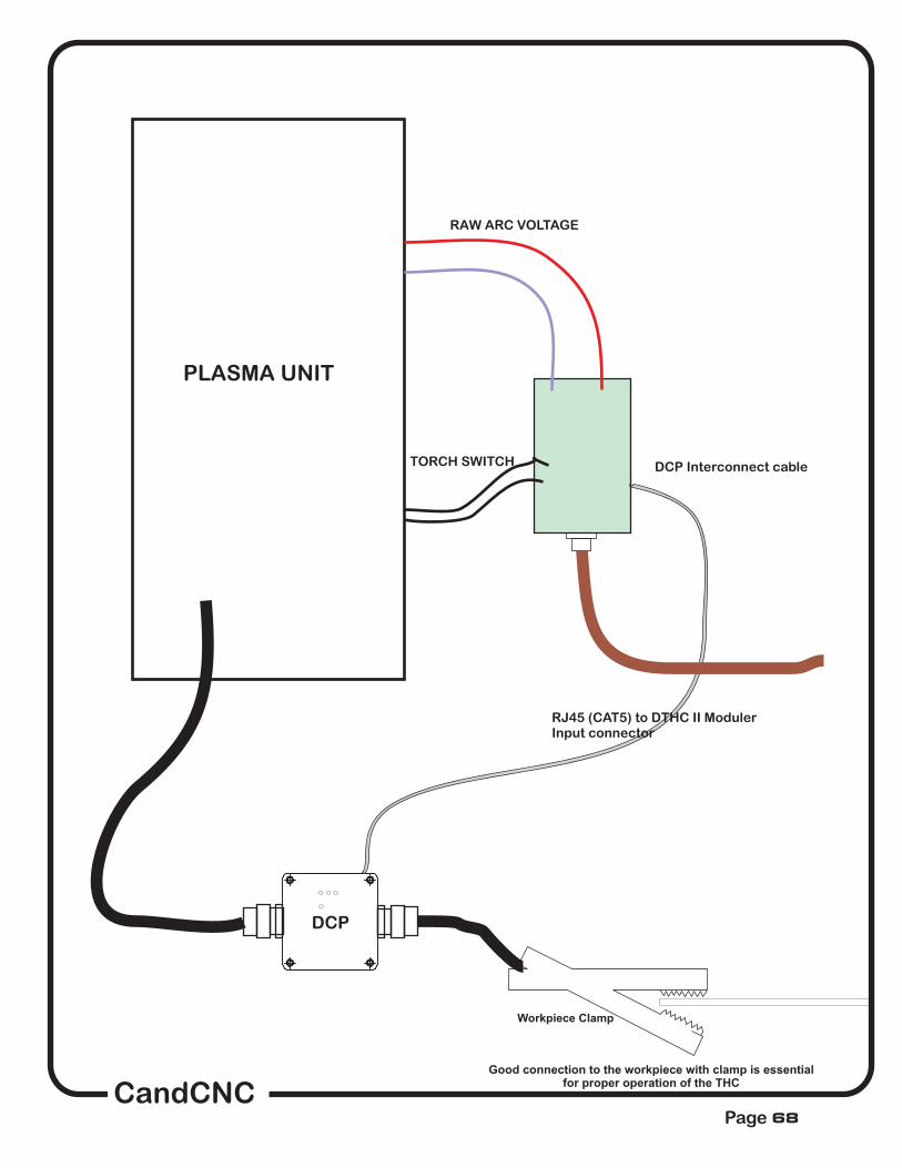
Workpiece Clamp
Good connection to the workpiece with clamp is essentialfor proper operation of the THC
RAW ARC VOLTAGE
TORCH SWITCH DCP Interconnect cable
DCP
PLASMA UNIT
RJ45 (CAT5) to DTHC II ModulerInput connector
CandCNCPage 68
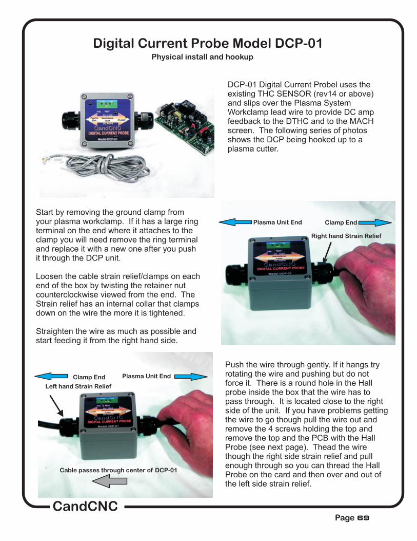
Digital Current Probe Model DCP-01
DCP-01 Digital Current Probel uses theexisting THC SENSOR (rev14 or above)and slips over the Plasma SystemWorkclamp lead wire to provide DC ampfeedback to the DTHC and to the MACHscreen. The following series of photosshows the DCP being hooked up to aplasma cutter.
Start by removing the ground clamp fromyour plasma workclamp. If it has a large ringterminal on the end where it attaches to theclamp you will need remove the ring terminaland replace it with a new one after you pushit through the DCP unit.
Loosen the cable strain relief/clamps on eachend of the box by twisting the retainer nutcounterclockwise viewed from the end. TheStrain relief has an internal collar that clampsdown on the wire the more it is tightened.
Straighten the wire as much as possible andstart feeding it from the right hand side.
Push the wire through gently. If it hangs tryrotating the wire and pushing but do notforce it. There is a round hole in the Hallprobe inside the box that the wire has topass through. It is located close to the rightside of the unit. If you have problems gettingthe wire to go though pull the wire out andremove the 4 screws holding the top andremove the top and the PCB with the HallProbe (see next page). Thead the wirethough the right side strain relief and pullenough through so you can thread the HallProbe on the card and then over and out ofthe left side strain relief.
Right hand Strain Relief
Left hand Strain Relief
Cable passes through center of DCP-01
Clamp End
Clamp End
Plasma Unit End
Plasma Unit End
Physical install and hookup
CandCNCPage 69
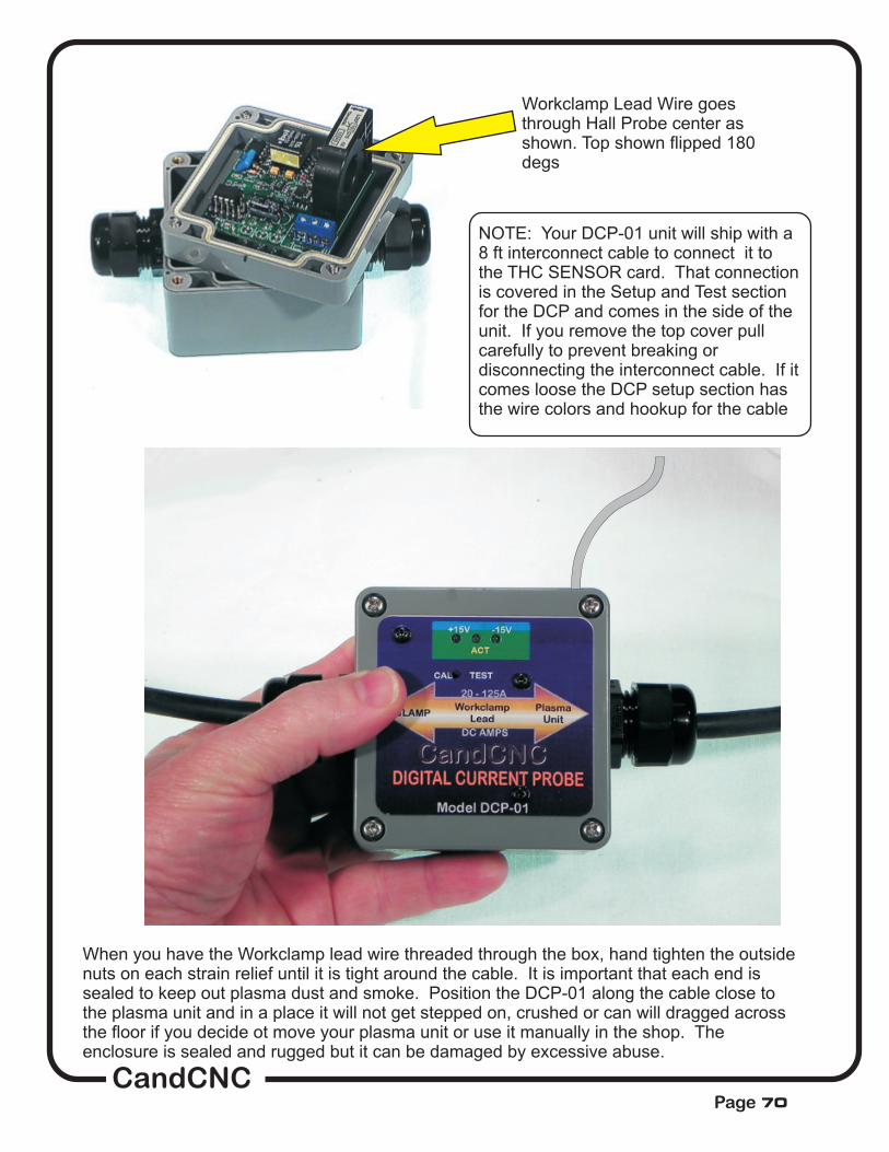
Workclamp Lead Wire goesthrough Hall Probe center asshown. Top shown flipped 180degs
NOTE: Your DCP-01 unit will ship with a8 ft interconnect cable to connect it tothe THC SENSOR card. That connectionis covered in the Setup and Test sectionfor the DCP and comes in the side of theunit. If you remove the top cover pullcarefully to prevent breaking ordisconnecting the interconnect cable. If itcomes loose the DCP setup section hasthe wire colors and hookup for the cable
When you have the Workclamp lead wire threaded through the box, hand tighten the outsidenuts on each strain relief until it is tight around the cable. It is important that each end issealed to keep out plasma dust and smoke. Position the DCP-01 along the cable close tothe plasma unit and in a place it will not get stepped on, crushed or can will dragged acrossthe floor if you decide ot move your plasma unit or use it manually in the shop. Theenclosure is sealed and rugged but it can be damaged by excessive abuse.
CandCNCPage 70
SETUP, TESTING and CALIBRATION of the DCP-01 DIGITAL CURRENT PROBE
Do the following steps in order:
1. Connect the DCP-01 interface cable (RJ11 flat silver to the THC SENSOR PWM frontpanel jack labeled DCP. You should get a postive “click” as the cable is seated. Removingthe cable should require releasing the locking pin
2. If your THC SENSOR is mounted in a box or inside the plasma unit then you will need tomake provisions to route the wire to the THC SENSOR. Keep the DCP interface cableaway from the high voltage TIP Volts end of the THC SENSOR card.
3. If you are connecting up your DTHC II and THC SENSOR PWM for the first time, makethe connections to the THC SENSOR PWM Module and the CAT5 cable back to the DTHCII module (front Panel connector on the MP3000-DTHC or the BladeRunner Dragon Cut.Do this BEFORE you make the Tip Volts (Arc volts) connection or the TORCH SWITCH.You can run some tests on the THC SENSOR Card and the DCP without having the plasmaunit turned on or the Tip Volts present.
CandCNCPage 71

4. Start MACH3 on the controller PC and load the profile and screen set for theDTHC. If this is the first time you have used the DTHC and MACH you should havehad MACH loaded and setup. If you do not, STOP! Go back to the MP3000-DTHCor the BladeRunner AIO manual and first setup MACH and get your table moving andthe proper MACH profile loaded for your system.
5. Power up the MP3000-DTHC or the BladeRunner (oryour UBOB Builders Kit + DTHC) so the DTHC modulehas power. The first thing you should see is that the +15LED and - 15 LED on the font of the DCP light up. TheACT (activity) LED will NOT be on.
This dialog box or one similar to itshould appear in the center part ofyour MACH main screen if you arerunning the right profile. Theimportant readouts (DRO’s) are theTORCH AMPS. We will be using theTORCH AMPS readout to calibratethe DCP and then use the StoredSettings Button to preset somevalues for the DCP. It’s importantthat you have gone through theDTHC setup in this manual FIRSTand that you have confirmed (usingthe DTCH self-test button that it isworking properly. The DTHCONLINE Led at the bottom should beON (Green). If it is NOT you cannotgo further in the DCP setup until theissue is resolved!
6.. Bring MACH out of reset. On any unit with our ESPsmart power controller (including Bladerunners) youMUST have the DC power to the motors on to come out ofreset. At this stage you should have MACH setup,running and know how to come out of reset.
7. Make sure that the DTHC II module is communicatingwith MACH. The DTHC ONLINE Led should be ON(green)
The TORCH VOLTS comes fromthe DTHC
When you activate the DTHC II Self-test theTORCH VOLTS should change from 100 to 150 andthe THC UP and THC DOWN leds (and ARC OK) willalternate off and on.
across the PC serial port connection toMACH. Without the serial communications you willnot get Torch Volts and you will not be able to seeTORCH AMPS
CandCNCPage 72

Calibration/Test Button(recessed)
8.. Once you have determined the DTHCpasses self-test then locate the small hole in thefront of the DCP unit (marked CAL and TEST).You will need a small screwdriver or probe tip(paperclip?). You will feel the button click. Pushit once to turn on the TEST/CAL function. Whenit is active the ACT LED (yellow) will flash.
9.. While you are in TEST/CALmode (LED blinking)the TORCH AMPS should display a value. If you areinstalling a DCP on an existing product with a DTHCthe calibration will be off so the number you seecould be anything from ___ to ____. I your unitdisplays 100 volts as shown then you continue on tofinal testing and CUT PROFILE Setup. IF YOURVOLTAGE IS NOT 100 You will need to proceed tothe CALIBARATION SECTION
CALIBRATION of the DCP-01Use this section any time you put the unit into TEST/CAL and the displayed value in
the TORCH APMS readout is NOT 100 as shown.
1. To calibrate the DTHC module to the DCP-01 you must have access to the top ofthe DTHC Expansion Module. Refer to your product manual to identify and access theDTHC module. It is the small PCB card behind the panel on all CandCNC units wherethe DB9 cable from the THC Sensor plugs in. In most cases all you have to do to gainaccess is remove the top cover (MP3000-DTHC) or the Front panel (BladeRunnerAIO). Use the photos below to find and identify the DTHC card and the correctadjustment point for the DCP. CAUTION there are two identical pots (variableresistors) in the card. One is the DCP calibration pot.
Check the photos. Study the board orientation and MAKE SURE you are adjusting thepot. This calibration should only have to be done once so take the time to do it right.
The other is the TORCHVOLTS calibration pot and is set at the factory DO NOT ADJUST THE WRONGPOT. IF YOU ACCIDENTLY CHANGE THE TORCH VOLTS (wrong pot) you willthrow your DTHC unit out of calibration and you will need to run the TEST/CALsequence on the THC SENSOR PWM module and reset the displayed volts.NOTE: SOME later rev’s of the DTHC II module may not have the arc voltscalibration pot. If it does not exist then ignore the above procedure.
TO TURN OFF TEST/CAL MODE on the DCP-01 push the recessed CAL/Test button onceand the ACT LED should stop flashing and theTORCH AMPS readout should return to 0
DCP Calibration (Cont)
CandCNCPage 73

DTHC EXPANION MODULE. Locatedabove the UBOB III card in most CandCNCproducts.. Ribbon cable connecting DTHCdown to UBOB card may cover adjustmentpots. If so, gently move it out out the way.Do not unplug the ribbon cable or the cardwill be disabled.
Green Power LEDShold be ON
16 pin header (plug)for DTHC to UBOBCable
DTHC Self TestLED
RJ45 connector for cable toTHC SENSOR CARD
TORCH VOLTS Calibration
Unit is calibrated at thefactory.
DO NOT ADJUST THIS POT.
NO!
DCP CalibrationPOT ADJUST perthe instructions
2. Using the diagram below and with theDCP in the TEST/CAL mode (LEDflashing) adjust the DCP calibration potwhile watching the TORCH AMPS DRO inthe MACH screen. Adjust the pot until thevalue displayed is 100 AMPs.
Your calibration procedure is complete!
CandCNCPage 74

OPERATION of the DTHCII with the DCP-01.
The primary purpose of the DCP-01 is to give the operator real time feedbackof the actual Cut Current. Using the settings in the Cut Profile you can setfault points (based on a percentage of the variance from the current presetvalue to warn the operator if cut current is too high or too low. The ACT LEDon the front of the DCP-01 (when not in Text/Cal mode) will light up anytimethe detected current is above 20A It’s just a visual indicator that the DCP-01 isreading current. If the LED lights when you fire the torch and have a valid arcand you do not see the Current displayed on the TORCH AMPS DRO on theMACH screen then go back through the test and calibration section. If yousee cut current out of range or get a Current Fault then check the workclampconnection, the current setting on the plasma unit, the consumables, the CutCurrent setting in the Cut Profile (stored settings) and determine why thecurrent is not what it should be.
you are running.
It’s important to understand that the CUT PROFILE does NOTthe cutting current. Only the manual adjustment on the plasma unit setsthat value. The DCP-01 just tells you what the cut current REALLY is atthe cut and tells you if the value is not what you have set in the specificCut Profile
set
This LED comes on any time detected current is 20A or greater
CandCNCPage 75

MP3000-DTHC Interface/Control Box
PLASMAUNIT
THC Sensor Card
PC w/MACH3
Tabel I/OCard(limits, homeAux relay)
Controller Cabinet
CNC PLASMA TABLE
Gantry
Ground Rod or Metal polein earth ground
#10 to #4 Ga heavy wire
#10 to #4 Ga heavy wire
Grounding plate
Attached to metalChassi
Do Ground PC or Controllers toEarth Ground Rod. Conrollers will reference themselves
to power ground through their AC lines
NOT
Note THC Sensor Card shielded cableis not connected to any ground in the Control box
Ground runs shouldbe less than 10’
Use ground strap to gantry from table
MP3000 and UBOB have built in isolation on all inputs from the tableto prevent noise transfer and ground loops
Grounding practices to reduce noise and increase safety
PAGE 76

1. DTHC does strange things after apierce (TIP SAVER locks on or tipplunges to the metal.)
2. UP and DOWN (LED’s) not comingon (no Z movement)
3. UP & DOWN LEDs work but no Zmovement
4. Z moves but erratically or losessteps.
5. UP or DOWN LED is on but Z stopsmoving (won’t go further down or up)Torch won’t cut low enough or highenough even though the UP or DOWNis on and THC Button is ON
6. Z DRO does not agree with actualheight at the end of a cut.
7. Torch pierces at wrong height
8. Torch cuts too Low/High. UP andDown and Z is working.
9. TIP SAVER comes on and stays on(it is normal for the TIP SAVER to flashon/off especially at the end of a cut orif the feedrate has slowed down. Onlymake changes if the cut quality is poor.
?
?
?
DTHC settings are wrong (wrong PRESETVOLTS).
Pierce delay too longTHC Delay in CUT PROFILE too SHORT.
Arc OK not working. DTHC not working (run self-test). MACH inputs not working.
THC button is OFF in MACH. MACH license notloaded.
Z motor tuning wrong.
THC Corrections (Max and Min) are set toolow/high. (settings tab in MACH). NOTE: MAX andMIN settings are in “units”. If you are running in MMunits you need to change both settings by a factor of25.4
Material has warped (a lot) OR Z is losing steps.for lost steps
Pierce height in G-code (from CAM) is set wrong.Touch-off values (switchoffset) are wrong. Z is losingsteps during a cut (see #6)
PRESET VOLTS is wrong for the material, tip andfeedrate you are using. Preset needs to beadjusted in 1 volt increments and in the samedirection as the error. Raise PRESET value to raisethe torch. Lower PRESET VOLTS value to lowerthe torch. DO NOT GUESS AT A VALUE! Run themanual cut test to establish the proper PRESETVOLTS value OR run the SMART-KUT option (onetime) if all of the pierce heights and beginning cutheight are correct.
TORCH VOLTS is above the PRESET. Turn offthe TIP SAVER or increase the percentage in theCUT PROFILE and try the cut. If it holds the correctheight then either increase the THC Delay in the cutprofile (NOT MACH) or increase the Tip Saverpercentage in the CUT PROFILE.
?
?
?
?
?
?
?
?
THC RATE setting inMACH too high.
Lower THC Rate in MACH
Troubleshooting DTHC Problems.
CandCNCPage 77

10. Torch oscillates wildly UP andDOWN while cutting
11. Torch slowly rises UP whilecutting
12. DTHC works fine sometimes andthen does not other times using thesame parameters.
13 Torch runes for a while then shutsoff while cutting or does not stay litafter the pierce.
? Torch is overshooting. Increase SPAN value inCUT PROFILE. Torch is losing steps. DecreaseTHC RATE by 5% in MACH. Check couplings andZ for binding or looseness.
Check Torch Volts reading. IF it is above thePRESET VOLTS then the DOWN LED should beon. If the TORCH is not going down then MACH isignoring the down command (THC Corrections iswrong) If the UP LED is on then the PRESETVOLTS maybe set wrong. If neither LED is on butthe torch moves up then Z is gaining steps fromoutside noise. Contact us. See also the TIPSAVER locking on issue.
Possible noise problem. Make sure you haveyour table and plasma well grounded with a localground rod. Try not to run your PC and Controllerout of the same subpanel as the plasma. keep thegorunds for each side separated locally.
Check the Indicator LED on the THC SENSORcard for the TORCH ON (relay) It should remainON steady. If the torch still turns off (with it on)then the problem is with a connection (torch switchterminals or a problem at the torch.
?
?
?
Do’s and Don’ts
run the manual cut test and record the conditions you see including the LED indicationsmake sure you understand that the setups for Touch-off, pierce height and cut height
are working correctlyhave the results of any testing ready for the support person.take the time to understand the basic concepts of how an ARC VOLTAGE THC (like the
DTHC) works.realize there are external conditions and torch problems that can effect the DTHC.follow all of the grounding rules for the plasma. HF start units need extra attention to
proper grounding for reliable operation.understand the relationships of Torch Volts, Torch AMPS, feedrate and air
pressure/quality in plasma cutting.
assume there is an electronics problem until you have eliminated ALL possibleproblems of incorrect settings and things like consumables and air
attempt to run plasma without the proper MACH Profile (XML) loaded. Must be aCandCNC profile or a copy from our profiles.
call for support with vague descriptions or having not tested to a pointmake changes in the MACH config to the base profile. Use a Clone copy and then
only make one change at a time. The pin settings (mappings) are complex for our systems
DODO
DODO
DODO
DO
DO NOT
DO NOT
DO NOTDO NOT
CandCNCPage 78

CandCNCPage
ALL CONTENT COPYWRITED 2011 - 2015
ALL RIGHTS RESERVED
The End


