
UC2
0100
3623
b EE
© M
edtr
onic
201
1. A
ll Ri
ghts
Res
erve
d. P
rinte
d in
Eur
ope
The procedure guide is an education and training supplement and is not intended to be a substitute for training. For more information, please refer to the Operator’s Manual and Instructions for Use, or contact your Medtronic representative.
Brief Statement
See the device manuals for detailed information regarding indications, contraindications, warnings, precautions, and potential adverse events.
Duty-Cycled Phased RF PROCEDURAl GUIDE
EuropeMedtronic International Trading SàrlRoute du Molliau 31Case postaleCH-1131 TolochenazTel: +41 (0)21 802 70 00Fax: +41 (0)21 802 79 00
United Kingdom/IrelandMedtronic ltdBuilding 9Croxley Green Business ParkHatters laneWatfordHerts WD18 8WWUKwww.medtronic.co.uk Tel: +44 (0)1923 212213Fax: +44 (0)1923 241004
www.medtronic.euwww.ablationfrontiers.com

32
REMOTE CONTROL
GENERATOR FOR
ABLATION CATHETERS
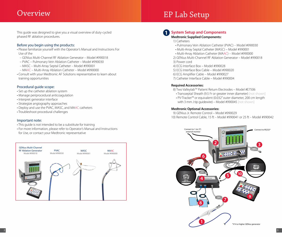
Connect to 1 (or 2*)external monitor
Connect to RS232*
*V14 or higher GENius generator
Overview
GENius Multi-Channel RF Ablation Generator
Model #990018 PVAC
Model #990030MASC
Model #990001MAAC
Model #990000
System Setup and ComponentsMedtronic Supplied Components: 1) Catheters •PulmonaryVeinAblationCatheter(PVAC)–Model#990030 •Multi-ArraySeptalCatheter(MASC)–Model#990001 •Multi-ArrayAblationCatheter(MAAC)–Model#990000 2)GENiusMulti-ChannelRFAblationGenerator–Model#990018 3) Power cord 4)ECGInterfaceBox–Model#990028 5)ECGInterfaceBoxCable–Model#990020 6)ECGAmplifierCable–Model#990027 7)CatheterInterfaceCable–Model#990004
Required Accessories: 8) Two ValleylabTMPatientReturnElectrodes–Model#E7506 •TransseptalSheath(9.5Frorgreaterinnerdiameter)[not shown] •PV-Tracker™orequivalent(0.032”outerdiameter,200cmlength
with3mmJtipguidewire)–Model#990045[not shown]
Medtronic Optional Accessories: 9)GENiusJr.RemoteControl–Model#99002910)RemoteControlCable,15ft–Model#990041or25ft–Model#990042
EP Lab Setup
32
105
97
1
8
6
4
This guide was designed to give you a visual overview of duty-cycled phased RF ablation procedures.
Before you begin using the products:•PleasefamiliarizeyourselfwiththeOperator’sManualandInstructionsFor
Use of the–GENiusMulti-ChannelRFAblationGenerator–Model#990018–PVAC–PulmonaryVeinAblationCatheter–Model#990030–MASC–Multi-ArraySeptalCatheter–Model#990001–MAAC–Multi-ArrayAblationCatheter–Model#990000
•ConsultwithyourMedtronicAFSolutionsrepresentativetolearnabouttraining opportunities
Procedural guide scope:•Setupthecatheterablationsystem•Manageperiproceduralanticoagulation•Interpretgeneratorinterface•Strategizeangiographyapproaches•DeployandusethePVAC,MASC,andMAAC catheters•Troubleshootproceduralchallenges
Important note:•Thisguideisnotintendedtobeasubstitutefortraining•Formoreinformation,pleaserefertoOperator’sManualandInstructionsforUse,orcontactyourMedtronicrepresentative
1

54
Patient Preparation•Firmlypressalongtheentireelectrodeareaduringplacement•Avoidareaswithadiposetissue,bonyprominences,fluidinvasion,scartissue,andexcesshair(shaveareaasnecessary)•Donotattempttoreposition;replaceifnecessary• Do not reuse (single use only)•InsertblueconnectorsfirmlyintoECGbox
EP Recording System Setup
Option 1
Option 2
* Applies to V12 or earlier.
3
2
EP Lab Setup
FEATURE VALUEGain One step more than the value used for a diagnostic
circular mapping catheterHigh pass 100HzLow pass 500HzClose pacing channels, where possible and when not actively delivering pacing stimuli
GENius-ECG Box Setup
Lead Amplifier Connectivity
4
5
6
Step 1: Connect the power cord at Step 2: Connect the ECG interface box thebackoftheGENius cablefromgeneratortoECG generator box (both ends of the cable are
identical and does not matter which end is connected to which part)
Step 1: The 12-lead ECG amplifier Step 2: Plug the ECG amplifier cable connects to the ECG into the ECG interface box interface box
EP Lab Setup
Step 1: Grasp the screen handle Step 2: Pull out screen completely
GENius Screen Setup
Step 3:Pressinbothknobson Step 4: Swing screen into place side of screen*
Step 5: Switch power on
REMOTE CONTROL
GENERATOR FOR
ABLATION CATHETERS
Connect to 1 (or 2*)external monitor
Connect to RS232*
*V14 or higher GENius generator
Multi-Channel RF Ablation Generator
ECG Interface Box
Remote
STOP
Standby StartAll
Channels
CH 1
CH 5
CH 2
CH 6
CH 3
CH 7
CH 4
CH 8
Temp Up
Temp Down
DurationUp
DurationDown
Bipolar Unipolar
1:1 2:1 4:1
GENERATOR
76
Loading dose after transseptal puncture 100U/kgHeparin administered during procedure 10U/kg/hourMonitoring Interval after achieving target ACT 30 minACT target range 300-350 seconds
350-400 seconds for significant atrial enlargement
To prevent sheath-related thrombi, heparinized-saline can be continuously infused via the transseptal sheath
Periprocedural Anticoagulation
Anticoagulation Strategies
•Summaryof“Anticoagulation and Strategies to Prevent Thromboembolism”from 2007 HRS/EHRA/ECAS Expert Consensus Statement1
Fredersdorf
JCE 2009
“…systemicanticoagulationwasachievedwithintravenous heparin to maintain an activated clotting time of≥300seconds.”2
Wieczorek
JCE 2009
“…andheparinwasadministeredintravenously,startingwithabolusof10,000IUuntilanactivatedclottingtimeof300–350swasobtained.”3
Scharf
JACC 2009
“Afterfemoralvenousaccessandtransseptalpuncture,asingle10.5-Fsheathwasinsertedintotheleftatrium,andheparin was administered to maintain an activated clotting time(ACT)>300s.”4
•Summaryofanticoagulationstrategiesfromselectpeer-reviewdata on phased RF
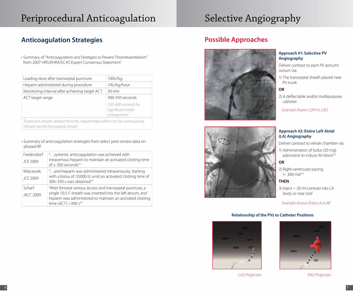
Approach #1: Selective PV Angiography
DelivercontrasttoeachPVantrum/ostium via:
1) The transseptal sheath placed near PVtrunk
OR
2) A deflectable and/or multipurpose catheter
Approach #2: Entire Left Atrial (LA) Angiography
Delivercontrasttowholechambervia:
1) Administration of bolus (20 mg) adenosinetoinduceAVblock5,6
OR
2) Right-ventricular pacing (~ 300 ms)6-8
THEN
3) Inject ~ 20 ml contrast into LA body or near roof
Possible Approaches
Example shown: LSPV in LAO
LAO Projection
Relationship of the PVs to Catheter Positions
Example shown: Entire LA in AP
RAO Projection
Selective Angiography
CSRIPV
RSPV
LAA
LIPV
LSPV
CS
RIPV
RSPV
LAA
LIPV
LSPV

98
Guidewire compatibility: •0.032”outerdiameter•200cmlengthorgreater•3mmJtip
Transseptal sheath compatibility:
•9.5Frorgreaterinnerdiameter
CURVE REACH40 mm at 90°
CURVE RADIUS19 mm
PAIR 2
TIP
PAIR 3
PAIR 1
PAIR 4
PAIR 5
6 5
4
3
1
10
9
8
7
ELECTRODES
3 mm
25 mmSPIRAL DIAMETER
3 mm
2
Product Specifications
145 cm ± 5 cm
105 cm ± 5 cm
9 Fr
SPIRAL ARRAY
CAPTURE DEVICE
TENSIONCONTROL KNOB
SLIDECONTROL KNOB
CONNECTORDISTALLUMEN PROXIMAL
LUMENSTEERING KNOB
Capture
1 •Inserttheproximalendofthe0.032"guidewireintothedistal end of the PVAC•TheguidewiremustexittheproximalendofthePVAC
•Removethecapturedevicefromthehandle•Slideuptothespiralarray2
•Holdthecapturedeviceagainstthespiralarray•Usetheotherhandtoadvancetheslidecontrolknobforward
on the handle (approximately ¼ of the travel)
3
•Slidethecapturedeviceforwardtocapturethespiralarrayonthedistal end •Continuetoadvancetheslidecontrolforwardascapturedeviceis
advancing forwardNote: Always lead the tip of the PVAC ahead of the capture device to preventkinkingofthedistallumen
4
5 •Thespiralarrayshouldlooklikethefigurebelow•Ifnot,pullbackslightlyonthecapturedevice,advancetheslide
control fully forward while capturing the tip of the spiral array with the capture device
Refer to Appendix on page 36 for Colored Arrow Chart
PVAC PVAC

1110
Insertion
•RetracttheguidewiretothedistaltipofthePVAC
•Insertthecapturedeviceintothehemostasisvalve
•Inserttheguidewirehalfwayintothetransseptalsheath
•Advancethearrayintothesheathbeforeremovingandreplacingthe capture device onto the handle
1
2 •Advancethecatheterthroughthetransseptalsheathuntilthearray enters the atrium
•Beforefullydeployingthecatheter,verifythattheguidewireisinthe left pulmonary vein
•Toensuretheguidewireexitsthesheathcorrectly,confirmthatentrapment does not occur in any existing sideholes
Deployment
•RetractthedistalendofthetransseptalsheathintotherightatriumtoallowforfulldeflectionofthedistalsegmentofthePVAC,asneeded
•Asthefourthelectrodeexitsthedistalendofthesheath,slowlypullbackontheslidecontrolknobwhilecontinuingtoadvancethe PVAC to deploy the spiral array
1
2
PVAC PVAC

1312
Navigation
•AdvancetheguidewireintotheselectedPV
•Advancethespiralarrayontotheantrum/ostium
•Donotretractguidewiretipcompletelyintoarrayinordertopreventkinkingofthedistaltip
1
2
•DonotattempttosteerthePVACwithinthesheath3
Catheter Maneuvers to Navigate the PVAC Array at the PV Antrum/Ostium
•Usethefollowingmaneuverstoimprovetissuecontact1
Steering•Bringsthearraytodifferent
areas of the antrum/ostium
•Changestheplaneof contact
•Increasestheareaofantral/ostial ablation
Rotating•Movestheelectrodearrayto
different antral/ostial positions
Pulling or pushing•Adjustscontactpressurewith
tissue
Sliding•Improvestheelectrode-tissue
contact
•Placesthearraywithinthevein
PVAC PVAC

1514
Navigating from Left-to-Right–Sided Veins
•ToaccessrightPVs,retracttheguidewiretothetipofthePVAC
•PointandsteerthePVACinanacutecurvetowardtheLIPV•Tightenthetensionknobenoughtoholdatightcurve
•Rotateclockwisetobringthearray posteriorly toward the right PV
1
2
3
Navigating Common Ostia
•Placingguidewireintodifferentveinbranchesallowsfor approaching the antrum/ostium using different planes9
•Slightlyadvancetheslidecontrolknob•Applycounterclockwisetorquetoexpandarray•Alwaysunlockthetensioncontrolknobwhennavigatingatthe
PV antrum/ostium
1
2
PVAC PVAC

1716
Mapping inside the Veins
•RetractthePVACfromtheantrum/ostiumofthevein•Advancetheslidecontrolknobhalfwayforward
•AdvancethearrayintotheveinwhilerotatingthePVAC counterclockwise
1
2
Generator Software Default Settings4
Target Temperature 60 °CAblationDuration 60 secPower Mode 4:1 (use 2:1 if needed to achieve isolation after
trying catheter maneuvers)
Suggested Ablation Strategy2-4,9,10
•Targetelectrodepairswithmostsignals during the first 4-5 ablations per vein
•SelectthedesiredpairsforRF
•Ifpowerindicationsare<3W, suggest the operator to reduce contact pressure by slightly pulling back(“PullforPower”)orde-energizeonly those low power channels*
•Rotate45°-90°between consecutive ablations•Advancethespiralarray
onto the tissue•Performadditional
ablations to touch up on resistant fascicles
•Alwayspullbackthearrayfrom the antrum/ostium before going to the next ablation
Recommended Setting for Ablating with PVAC
(continued) * Low power channel is presumably a result of reduced cooling due to the electrode being deeply embedded in tissue. See page 33 for Managing Temperature and Power.
PVAC PVAC

1918
•PVACisdesignedtoablateatpulmonaryvein antrum/ostium
•Usefluoroscopicvisualizationtoconfirmlocation to prevent ablating the left atrial septum and posterior wall
•PVACisdesignedtoablateatpulmonaryvein antrum/ostium
•Usefluoroscopicvisualizationtoconfirmlocation to prevent ablating the left atrial wall with PVAC fully extended
•Ifitbecomesdifficulttowithdrawthetip of the PVAC into the distal end of the sheath,removethesheathwiththePVACcontained inside
Note:Donotallowelectrodes1and10 to come in contact with each other. Instead:•PerformPVACmaneuvers(sliding, rotating,steering,pushing,orpulling)
OR•Ensure electrodes 1 and 10 are separated
prior to ablating
•Usefluoroscopicvisualizationtonavigate the PVAC to different ablation location
•Prior to consecutive ablation in the samelocation,waitforappropriatetissue cooling to occur
Recommended Setting for Ablating with PVAC (continued)
PVAC
Validation of Pulmonary Vein Isolation (PVI)
Entrance Block
•WithPVACplacedatthedistalofthepresumedablationline,checkforentranceblockbymappingduringsinusrhythm,distalCSpacing(forLPVs),proximalCSpacing(forRPVs),orHighRightAtrialpacing(forRPVs)10,11
Differential Pacing
•UsedifferentialpacingorevaluatetheP-wavetoavoidmisinterpretationduetofar-fielddetection,e.g.,LAAinLSPV,RAinRSPV12
Exit Block
•PlacethePVACarraywithinthetargetedPV
•PaceathighoutputfromeachofthePVACpairs,checkingtheeffectonPVand atrial activations11,13
PVAC

2120
Removal
•EnsurethePVACisstraight•Verifyatleast5cmofguidewireisinsertedintooneoftheLPVs•Advanceslidecontrolknob¼forwardandpullbackonthePVAC
shaft to retract the array into the sheath
•Continuetoadvancetheslidecontrolwhilesimultaneously retracting the PVAC
1
2
3
Reinsertion
•Removetheguidewire from the PVAC
•Flushtheguidewirelumen using heparinizedsaline
•Cleantheguidewire and makesurethewireis free of debris
•Reinsert the guidewire into the PVAC
PVAC
•Insertthecapturedeviceintothehemostasisvalve•ContinueretractingthePVACuntilthearrayis
located in the capture device•Removethecapturedevicewiththespiralarray
and the guidewire from the valve of the sheath
Transseptal Sheath Compatibility:•9.5Frorgreaterinnerdiameter
26 mm
135 cm ± 5 cm105 cm ± 5 cm
8.5 Fr 9 Fr
ARM 1 MARKER
ARM 2 MARKERS
ELECTRODES PAIR 1
PAIR 2
12
4mm
2mm
2mm
2mm
34
PAIR 3
PAIR 4
PAIR 5PAIR 6
8
9 10 1112
76
5
6mm6mm
26 mm
135 cm ± 5 cm105 cm ± 5 cm
8.5 Fr 9 Fr
ARM 1 MARKER
ARM 2 MARKERS
ELECTRODES PAIR 1
PAIR 2
12
4mm
2mm
2mm
2mm
34
PAIR 3
PAIR 4
PAIR 5PAIR 6
8
9 10 1112
76
5
6mm6mm
Product Specifications
MASC

2322
Capture
Capture and Insertion
1
2
•Removethecapturedevicefromthehandleandslideituptothearray
•Advancetheslidecontrolknobonthehandleforwardcompletelyand hold in position
•Slidethecapturedeviceoverthedistalarray
Insertion•Insertthecapturedeviceintothehemostasisvalve
•AdvancetheMASCintothesheathapproximately15cm
•Slidethecapturedevicebackintoplaceonthehandle
MASC
•AdvancetheMASCthroughthesheathuntilthearrayenterstheleft atrium
•Thedistalportionofthearraymustexitthesheathpriortoretractionoftheslidecontrolknob
•Astheslidecontrolknobisretracted,simultaneouslyretractthesheathbackintotheRA
1
2
Deployment
MASC
Refer to Appendix on page 36 for Colored Arrow Chart

2524
Generator Software Default Settings4
Target Temperature 60 °CAblationDuration 60 secPower Mode 1:1
Navigation and Ablation
1
2
•Verifythetipofthesheathdoesnotextendintotheleftatrium
•PulltheMASCbacktoengagetheelectrodesagainsttheleftatrialseptum
MASC
•SelectthedesiredpairsforRF•Ifpowerindicationsare<3W,slightlypushforwardoradjustthecontrolknobonthehandle.(Thisisanindication that the electrode is deeply embedded in the left atrial septum.)
Navigation and Ablation (continued)
3
4Reposition the Array
MASC
Step 1: Slightly advance the controlknob
Step 3: Rotate the array to a new position
Step 2:Pushthearrayforward,away from the septum
Step 4: •Retracttheslidecontrolknobbacktodeploythearray•RetracttheMASCtoengagethe
electrodes against the septum•Ablateasnecessary•RepeatuntiltheMASChas been
rotated 360°
•Donotattempttorotatethecatheter while the array is against the septum
•Usefluoroscopicvisualizationto confirm the array arms are separated before delivering RF energy
2726
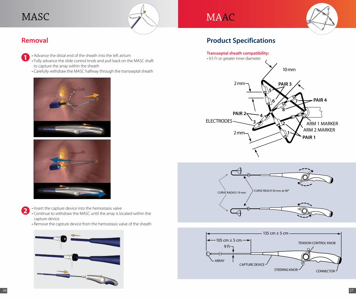
•Advancethedistalendofthesheathintotheleftatrium•FullyadvancetheslidecontrolknobandpullbackontheMASCshaft
to capture the array within the sheath•CarefullywithdrawtheMASChalfwaythroughthetransseptalsheath
1
2 •Insertthecapturedeviceintothehemostasisvalve•ContinuetowithdrawtheMASCuntilthearrayislocatedwithinthe
capture device•Removethecapturedevicefromthehemostasisvalveofthesheath
Removal
MASC
105 cm ± 5 cm9 Fr
TENSION CONTROL KNOB
CAPTURE DEVICEARRAY
CONNECTOR
135 cm ± 5 cm
STEERING KNOB
PAIR 4
PAIR 3
PAIR 2ELECTRODES
2 mm
10 mm
PAIR 1
5
6 7
8
1
234
ARM 1 MARKER ARM 2 MARKER 2 mm
CURVE REACH 50 mm at 90oCURVE RADIUS 19 mm
Product Specifications
Transseptal sheath compatibility: •9.5Frorgreaterinnerdiameter
MAAC

2928
•Removethecapturedevicefromthehandleandslideitupto the array
•Beginslidingthecapturedeviceforwardtocapturethearray
1
2
Capture and Insertion
Capture
Insertion
•Insertthecapturedeviceintothehemostasisvalve
•AdvancetheMAAC into the sheath approximately 15 cm
•Slidethecapturedevicebackintoplaceonthehandle
MAAC
•Usefluoroscopicvisualizationtoconfirmthedistalendofthe sheath is not against any structure of the heart
•AdvancetheMAAC through the sheath until the array enters the left atrium
•Asthearrayexitsthedistalendofthesheath,advancetheMAAC and retract the sheath into the right atrium to enable full deflection of the MAAC
1
2
Deployment
MAAC
Refer to Appendix on page 36 for Colored Arrow Chart

3130
Generator Software Default Settings4
Target Temperature 60 °CAblationDuration 60 sec (30 sec on thin LA walls)Power Mode 1:1
•Usingthesteeringknoblocatedonthehandle,deflectthetipinthedirection of interest within the atrium for mapping and ablation
•Tightenthetensioncontrolknobtomaintaincurveconfiguration
•DonotattempttosteertheMAAC within the sheath
Navigation and Ablation
1
2
MAAC
Navigation and Ablation (continued)
MAAC is designed for atrial navigation. If ventricular signals are detected by the MAAC:
•Rotateclockwisetowardsthepostero-lateralwallwheninthe left atrium
•Usefluoroscopicvisualizationtoensureanatomicallocation of MAAC in the left atrial body and away from the area of the mitral valve
4
MAAC
•SelectthedesiredpairsforRFdelivery.Ifpowerindicationsare<3W,pullbackslightlyoradjustthecontrolknobonthehandle.(Thisisanindication that the electrode is deeply embedded into the tissue.)
3
Pair 1

3332
•Advancethedistalendofthesheathintotheleftatrium•EnsuretheMAAC is straight•Neutralizethesteeringknobandloosenthetensioncontrolknob
•SlowlyretracttheMAAC into the sheath to capture the array•WithdrawMAAC approximately halfway through the sheath
1
2
Removal
•Insertthecapturedeviceintothehemostasisvalve•PulltheMAAC array into the capture device •Removethecapturedevicefromthehemostasisvalveofthesheath
3
MAAC
Scenario 1: EFFECTIVE Lesion Creation: Good Contact + Good Cooling•Greenbarsindicatetargettemperatureisreached(±5°C)•Powerdeliveryof5-7Wsuggestsgoodcontactandeffectiveelectrodecooling
(Max Power in 4:1 = 8 W)
Scenario 2: EFFECTIVE Lesion Creation: Low Contact/High Cooling•BluebarsindicatetargettemperaturehasNOTbeenreached,buttemperature>50°C
appropriate for lesion creation•Maxpowerdeliveryof8WsuggestshighfloworMarginal Tissue Contact•Gently INCREASING contact pressure may increase temperature to green range
(“Push for Green”)
Scenario 3: INEFFECTIVE Lesion Creation: High Contact/Low Cooling•Greenbarsindicatetargettemperatureisreached(±5 °C)•Powerdeliveryof<3Wsuggestslowfloworlimitedcooling(“Buried Electrode”)•GentlyDECREASING contact pressure may improve cooling by exposing more electrode
surface to blood and result in increased power delivery (“Pull for Power”)
Scenario 4: INEFFECTIVE Lesion Creation: Low/No Contact•Bluebars<45°Csuggesttissuecontactisminimal
•Maxpowerdeliveryof8WsuggestsLimited Tissue Contact
•GentlyINCREASING contact pressure may increase temperature to green range (“Push for Green”)
Managing Temperature and Power
General Properties of an Effective Lesion:•Power>3W•Temperature>50°C
•QuickThermalResponseatOnsetofRFdelivery•StableTemperatureafterInitial“RampUp”•StableArrayPositionduringRFapplication

3534
•Unplugandre-plugthecathetercable•PushSTOPonGENius
•Replacethecathetercable•PushSTOP
•Unplug and re-plug all of the cables from the ECG interface box and from GENius front panel
•PushSTOP on GENius
•Replacethecatheter•PushSTOP
PleaserefertotheGENiusOperator’sManualorcontactyour Medtronic representative.
1
2
3
4
General Steps
Troubleshooting
2
31
4
General Procedural Reminders Situations1 Ensure correct patient return
electrode patch model is used and placed appropriately on the body. Donotreusepatches(singleuseonly).
Inadequateadhesionandimproperplacement may cause potential for superficial lesions due to reduced unipolar current path.
2 Follow proper use of energy mode for each catheter type.
Use of non-default energy modes may increaseriskofcollateraldamageorother adverse events.
PVAC Procedural Reminders Situations3 Always use PVAC with a compatible
guidewire. Use fluoroscopic visualizationtoconfirmguidewireis NOT withdrawn past the distal tip of the PVAC.
Use of a PVAC without the guidewire mayleadtokinkinganddamagetothe guidewire lumen.
4 PVAC is designed to ablate at PV antrum/ostium. Use fluoroscopic visualizationtoconfirmlocationtoprevent ablating in the left atrial septum and posterior wall with PVAC fully extended.
Inaccurate temperature measurement mayleadtoanincreasedriskofcollateral damage or other adverse events.
5 Donotallowelectrodes1and10 to come in contact with each other.
Overlapping electrodes may increase bipolar current density and possibly “overdrive”temperatures;maytrigger“shortcircuit”or“channelfault”message.
6 Rotate the PVAC 45°-90° between RF applications.
Array rotation allows time for electrode and tissue cooling and potentially prevent ineffective lesion formation.
7 Move the array to a different location or position before continuing RF application.
PerformingrapidsequentialRFapplicationmaycauseinadequatecooling and inaccurate temperature measurements.
MASC Procedural Reminder Situation8 Confirm the 3 array arms are
separated on fluoroscopy before delivering RF energy.
Attached arms may increase current densityandpossibly“overdrive”temperatures;maytrigger“shortcircuit”or“channelfault”message.
MAAC Procedural Reminder Situation9 Toavoidentrapment,use
fluoroscopicvisualizationtosteer away from the mitral valve. Applyclockwisetorqueshouldentrapment occur.
MAACinmitralvalvemaycauserisksofentrapment.
Important Procedural Reminders

3736
Appendix
ACT Activated clotting time
AP Anterior posterior
CS Coronary sinus
LA Left atrium
LAA Left atrial appendage
LAO Leftanterioroblique
LIPV Left inferior pulmonary vein
LPV Left pulmonary vein
LSPV Left superior pulmonary vein
PV Pulmonary vein
PVI Pulmonary vein isolation
RA Right atrium
RAO Rightanterioroblique
RF Radiofrequency
RIPV Right inferior pulmonary vein
RSPV Right superior pulmonary vein
1 CalkinsH,BrugadaJ,PackerDL,etal.HRS/EHRA/ECASexpertConsensusStatementoncatheter and surgical ablation of atrial fibrillation. Heart Rhythm.June2007;4(6):816-861.
2 FredersdorfS,WeberS,JilekC,etal.Safeandrapidisolationofpulmonaryveinsusinganovel circular ablation catheter and duty-cycled RF generator. J Cardiovasc Electrophysiol. October2009;20(10):1097-1101.
3 WieczorekM,HoeltgenR,AkinE,SaliliAR,OralH,MoradyF.Resultsofshort-termandlong-term pulmonary vein isolation for paroxysmal atrial fibrillation using duty-cycled bipolar andunipolarradiofrequencyenergy.J Cardiovasc Electrophysiol.April2010;21(4):399-405.
4 ScharfC,BoersmaL,DaviesW,etal.Ablationofpersistentatrialfibrillationusingmultielectrodecathetersandduty-cycledradiofrequencyenergy.J Am Coll Cardiol. October6,2009;54(15):1450-1456.
5 TseHF,LeeKL,LauCP.Adenosinetriphosphateenhancedcontrastpulmonaryvenogramtofacilitate pulmonary vein ablation. J Cardiovasc Electrophysiol.March2002;13(3):300.
6 EctorJ,DeBuckS,NuyensD,etal.Adenosine-inducedventricularasystoleorrapidventricular pacing to enhance three-dimensional rotational imaging during cardiac ablation procedures. Europace.June2009;11(6):751-762.
7 TangM,KriatselisC,YeG,etal.Reconstructingandregisteringthree-dimensionalrotational angiogram of left atrium during ablation of atrial fibrillation. PACE. November 2009;32(11):1407-1416.
8 Gerds-LiJH,TangM,KriatselisC,etal.Rapidventricularpacingtooptimizerotationalangiography in atrial fibrillation ablation. J Interv Card Electrophysiol.November2009;26(2):101-107.
9 BoersmaLV,WijffelsMC,OralH,WeverEF,MoradyF.Pulmonaryveinisolationbyduty-cycledbipolarandunipolarradiofrequencyenergywithamultielectrodeablationcatheter.Heart Rhythm.December2008;5(12):1635-1642.
10 Asirvatham SJ. Pulmonary vein-related maneuvers: part I. Heart Rhythm.April2007;4(4):538-544.
11ShahD.Electrophysiologicalevaluationofpulmonaryveinisolation.Europace. November 2009;11(11):1423-1433.
12ShahD,BurriH,SunthornH,Gentil-BaronP.Identifyingfar-fieldsuperiorvenacavapotentialswithin the right superior pulmonary vein. Heart Rhythm.August2006;3(8):898-902.
13GerstenfeldEP,DixitS,CallansD,etal.Utilityofexitblockforidentifyingelectricalisolationof the pulmonary veins. J Cardiovasc Electrophysiol.October2002;13(10):971-979.
References
Common Abbreviations
Colored Arrow ChartThe directions and manipulations of catheter motions are indicated by the different colors of arrows
Arrow Colors DefinitionsSlidingorTension-knobturning
•Indicatesslidingmotionofcapturedeviceorslidingknobtocapturethespiralarray
Or•Indicatesturningoftensionknobtolockorunlockcurveconfiguration
Steering •Indicatessteeringofsteeringknobtonavigate the electrode array in the left atrium
Rotating •Indicatesrotatingcatheterhandletorotatethe electrode array
Pushing or Pulling •Indicatespushingorpullingofcatheterhandletoadvanceorpullbacktheshaft
Reminder •Safepracticerecommendations


