
C1 - 01 - Cover SheetC2 - 02 - Disclaimer - Site ReadinessA1 - 03 - General NotesA2 - 04 - Equipment LayoutA3 - 05 - Section ViewsA4 - 06 - Acoustic - VibrationA5 - 07 - RF ShieldingA6 - 08 - Equipment Dimensions (1)A7 - 09 - Equipment Dimensions (2)A8 - 10 - DeliveryS1 - 11 - Structural NotesS2 - 12 - Structural Layout
S3 - 13 - Structural DetailsM1 - 14 - Mechanical LayoutM2 - 15 - HVAC - Chilled WaterM3 - 16 - Chilled WaterM4 - 17 - Mechanical DetailsM5 - 18 - CryogenicsE1 - 19 - Electrical NotesE2 - 20 - Electrical LayoutE3 - 21 - Electrical ElevationE4 - 22 - Electrical DetailsE5 - 23 - Power RequirementsE6 - 24 - Interconnections
----
----
SIGNA ARTIST / OPTIMA MR450W
PMM
GE Healthcare
GE does not take responsibility for any damages resulting from changes on drawings made by others. Errors may occur by not referring to the completeset of final issue drawing. GE cannot accept responsibility for any damage due to the partial use of GE final issue drawings, however caused. Alldimensions are in millimeters unless otherwise specified. Do not scale from printed pdf files. GE accepts no responsibility or liability for defective work
due to scaling from these drawings. /24EN-MRI-TYP-OPTIMA_MR450W-WEB.DWG
----
----
PMM 5670001
----
1/4"=1'-0"
----
10/Jul/2018
Typical
A mandatory component of this drawing set is the GE Healthcare Pre Installation manual. Failure to reference the Pre Installation manual will result inincomplete documentation required for site design and preparation.
Pre Installation documents for GE Healthcare products can be accessed on the web at: www.gehealthcare.com/siteplanning -
Drawn by Verified by PIM Manual
SheetFormat
Concession
Scale DateFile Name
RevS.O. (GON)
A3
11
REV DATE MODIFICATIONSA 10/Jul/2018 First issue drawing / Final study based on MRI-
FINAL STUDY
01

Customer Name: PMI Name:
GON/SO Number: Field Service Name:Equipment: Country/City or City/State:Required site assessment milestones Date of completion (dd/mm/yyyy)1) Check site before Magnet Delivery
2) Check site before installation start
Place an "X" in either Y or N column
Site Ready Checks at Installation Y NGeneral Site Planning
Room dimensions, including ceiling height, for all Exam, Equipment/Technical & Control rooms meets GE specifications.
Ceiling support structure, if indicated on the GE drawing, is in the correct location and at the correct height according to theOriginal Equipment Manufacturer specifications. Levelness and spacing has been measured, and is ready for the installationof any GE supplied components. Overhead support Structure has been confirmed with customer/contractor to meet requiredGE provided criteria.
Rooms that will contain equipment, including staging areas if applicable, are construction debris free. Precautions must betaken to prevent debris from entering rooms containing equipment.
Finished ceiling is installed. If applicable ceiling tiles installed per PMI discretion.
Adequate delivery route from truck to final place of installation has been reviewed with all stakeholders, allcommunications/notifications have occurred, arrangements have been made for special handling (rigging, elevator, fork lift,etc.). All floors along delivery route will support weight of the equipment, temporary reinforcements arranged if needed.
System power & grounding (PDB/MDP) is available as per GE specifications, installed at point of final connection and ready touse. Lock Out Tag Out is available.
System power and grounded audit has been scheduled to be completed during installation of equipment. (If Required) GEHCPM to confirmed if needed.
Adequate room illumination installed and working.
Cable ways (floor/wall/ceiling/Access Flooring) are available for installation of GE cables and are of correct length anddiameter. Cable ways routes per GE Final drawings and cable access openings areas installed at a time determined by GEHCPM. Surface floor duct can be installed at time of system installation.
HVAC systems Installed, and the site meets minimum environmental operational system requirements.
Network outlets installed and computer network available and working.
Hospital IT/connectivity contacts have been engaged and information has been added to Project management tool. (IfRequired)
Floor levelness/flatness is measured and within tolerance, and there are no visible defects per GEHC specifications. FloorStrength and thickness have been discussed with customer/contractor and they have confirmed GE requirements are met.
Customer supplied countertops where GE equipment will be installed are in place.
Specific for MR
RF Shield installed with possible exception of magnet entrance. RF Shield Effectivity and Ground Isolation Test needed. If GEresponsible for supplying RF shield, the RF shield Effectivity and Ground Isolation Test data is a Mandatory attachment intoMyProjects.
Power and connectivity is available for magnet monitoring.
Delivery route for He dewars & gradient coil cart to the scanning room is available.
Chilled water supply for Water Cooled Compressor or Air Cooled Compressor is ready and meets GE specifications.
Water drain available in the equipment room, if applicable.
Power for MR compressor & Chiller is available.
Ensure cryogen venting system is available for magnet connection.
Exhaust fan system is installed and operational per GE requirements.
Status of work
General commentsSystem can be delivered PMI signature
Site ready for installation FS signature: optional
GLOBAL SITE READINESS CHECKLIST (DI)DOC1809666 Rev. 5
GENERAL SPECIFICATIONS
GE is not responsible for the installation of developers and associated equipment, lighting, cassette trays andprotective screens or derivatives not mentioned in the order. The final study contains recommendations for the location of GE equipment and associated devices, electrical
wiring and room arrangements. When preparing the study, every effort has been made to consider everyaspect of the actual equipment expected to be installed.
The layout of the equipment offered by GE, the dimensions given for the premises, the details provided forthe pre-installation work and electrical power supply are given according to the information noted duringon-site study and the wishes expressed by the customer.
The room dimensions used to create the equipment layout may originate from a previous layout and may notbe accurate as they may not have been verified on site. GE cannot take any responsibility for errors due tolack of information. Dimensions apply to finished surfaces of the room. Actual configuration may differ from options presented in some typical views or tables. If this set of final drawings has been approved by the customer, any subsequent modification of the site must
be subject to further investigation by GE about the feasibility of installing the equipment. Any reservationsmust be noted. The equipment layout indicates the placement and interconnection of the indicated equipment components. There may be local requirements that could impact the placement of these components. It remains thecustomer's responsibility to ensure that the site and final equipment placement complies with all applicablelocal requirements.
All work required to install GE equipment must be carried out in compliance with the building regulations andthe safety standards of legal force in the country concerned.
These drawings are not to be used for actual construction purposes. The company cannot take responsibilityfor any damage resulting therefrom.
CUSTOMER RESPONSIBILITIES
It is the responsibility of the customer to prepare the site in accordance with the specifications stated in thefinal study. A detailed site readiness checklist is provided by GE. It is the responsibility of the customer toensure all requirements are fulfilled and that the site conforms to all specifications defined in the checklist and final study. The GE Project Manager of Installation (PMI) will work in cooperation with the customer to followup and ensure that actions in the checklist are complete, and if necessary, will aid in the rescheduling of thedelivery and installation date.
Prior to installation, a structrual engineer of record must ensure that the floor and ceiling is designed in such away that the loads of the installed system can be securely borne and transferred. The layout of additionalstructural elements, dimensioning and the selection of appropriate installation methods are the soleresponsibility of the structural engineer. Execution of load bearing structures supporting equipment on theceiling, floor or walls are the customer's responsibility.
DISCLAIMER
THE UNDERSIGNED, HEREBY CERTIFIES THAT I HAVE READ AND APPROVED THE PLANS IN THIS DOCUMENT.
DATE NAME SIGNATURE
DateRev /24EN-MRI-TYP-OPTIMA_MR450W-WEB.DWG A 10/Jul/2018SIGNA ARTIST / OPTIMA MR450WTypical C2 - Disclaimer - Site Readiness 02

TYPCIAL MOVING MAGNETIC MASS DISTANCE RADIALLY DISTANCE AXIALLYCarts, Gurneys 100-400 lbs [45-182 kg] 3 Gauss line 3 Gauss line
Forklifts, small elevator, cars, minivans vans, pickup trucks, ambulances(objects greater than 400 lbs [182 kg]) 15.5 FT 4.72 M 24.6 FT 7.5 M
Buses and trucks (dump, tractor trailer, utility, fire trucks) 18.1 FT 5.52 M 28.75 FT 8.76 M
MAGNETIC INTERFERENCE SPECIFICATIONS
The customer must establish protocols to prevent persons with cardiac pacemakers, neurostimulators, andbiostimulation devices from entering magnetic fields of greater than 5 gauss (exclustion zone).
Main power transformers must remain outside the 3 gauss field. EMI < 20mg rms ac. EMI < 5.87mg dc. Potential exists under fault conditions that the 5 gauss line may expand radially to 9.35 ft. [2.85 m] and axially
to 14.27 ft. [4.35 m] for 1 seconds or less. It should be noted that normal rampdowns or magnet rundown unitinitiated quenches will not cause the magnetic field to expand.
It is recommended every site consider the event of a quench and plan accordingly (such as placing 5 gausswarning signs at expanded locations).
The ferrous metal objects listed below must not move into or inside of the moving metal sensitivity line duringscans.
Any deviation from these drawings must be communicated in writing to and reviewed by your local GEHealthcare Installation project manager prior to making changes.
Make arrangements for any rigging, special handling, or facility modifications that must be made to deliverthe equipment to the installation site. If desired, your local GE Healthcare Installation project manager cansupply a reference list of rigging contractors.
New construction requires the following;1. Secure area for equipment,2. Power for drills and other test equipment,3. Capability for image analysis,4. Restrooms.
Provide for refuse removal and disposal (e.g. crates, cartons, packing)
It is the customer's responsibility to contract a vibration consultant/engineer to implement site designmodifications to meet the GE vibration specification. Refer to the system preinstallation manual for thevibration specification.
CUSTOMER SITE READINESS REQUIREMENTSPlease refer to pre-installation checklist in pre-installation manual listed on the cover sheet for items critical toimage quality.
1. The layout should be arranged so that the 5g line is contained to the magnet room. If not possible, a barrier isrecommended to prevent entry to the 5g field area.
2. The spaces around, above, and below the magnet must be reviewed for effects of the 5g, 3g, 1g, and .5g fields.Refer to the proximity limit chart in the MR pre-installation manual referenced on the cover sheet.
3. For moving metal, the restriction lines typically extend outside of the MRi space. Please confirm there are nomoving metal concerns within these areas. An EMI study is recommended if the restriction lines are violated.
4. For vibration, analysis to be completed as required per pre-installation manual.5. For emi, review the site for the location of the main electrical feeders, ac devices, or distribution systems. An
EMI study is recommended if large ac systems are nearby.6. Details of the floor below the magnet must be reviewed. The structural engineer must verify that the quantity
of steel in the volume 10ft [3.1m] x 10ft [3.1m] x 1ft [.3m] deep (below the magnet) does not exceed theallowable steel content as given in the MR pre-installation manual referenced on the cover sheet.
7. All access/computer flooring is to be removed in both the magnet room and equipment room.
Responsibility for the coordination, design, engineering, and site preparation resides with the customer and theirproject architects and contractors. GE does not, by providing reviews and furnishing comments and assistance,accept any responsibility beyond its obligations as defined in the MR system, sale/purchase agreement.
MRi SITE PLANNING REMINDERS
Broadband RF noise is a single transient or continuous series of transient disturbances caused by an electricaldischarge. Low humidity environmental conditions will have higher probability of electrical discharge. The electricaldischarge can occur due to electrical arcing (micro arcing) or merely static discharge. Some potential sourcescapable of producing electrical discharge include:
Loose hardware/fasteners vibration or movement (electrical contunuity must always be maintained) Flooring material including raised access flooring (panels & support hardware) and carpeting Electrical fixtures (i.e. Lighting fixtures, track lighting, emergency lighting, battery chargers, outlets) Ducting for hvac and cable routing RF shield seals (walls, doors, windows etc.)
For additional information regarding image quality, refer to the pre-installation manual listed on the cover sheet.
IMAGE QUALITY CONSIDERATIONS
DateRev /24EN-MRI-TYP-OPTIMA_MR450W-WEB.DWG A 10/Jul/2018SIGNA ARTIST / OPTIMA MR450WTypical A1 - General Notes 03

BY ITEM DESCRIPTIONMAX HEAT
OUTPUT(btu)
WEIGHT(lbs)
MAXHEAT
OUTPUT(W)
WEIGHT(kg)
A 1 1.5T Magnet 8189 11173 2400 5068
A 2 Rear pedestal - 212 - 96
A 3 GEM Patient table - 463 - 210
A 4 Magnet rundown unit - 7 - 3.2
A 5 Phantom set storage cabinet - 350 - 136
A 6 Blower box 1535 - 450 -
A 7 Penetration cabinet 1024/10697 639 300/
3135 290
A 8 Secondary penetration wall - 92 - 45
A 9 Power, gradient, RF cabinet 20940 3144 6137 1426
A 10 Heat exchanger cabinet 3412 1350 1000 612
A 11 Magnet monitor 819 10 240 4.5
A 12 Cryocooler compressor 1706 264 500 120
A 13 Operator console computer 4947 141.75 1450 64.3
A 14 Operator workspace - 26 - 11.80
A 15 Pneumatic patient alert - 0.5 - 0.2
D 16 MR Elastography 480 53.4 0.14 24.22
D 17 700 va partial UPS - 26 - 12
D 18 CCTV Monitor - 8.27 - 3.75
D 19 CCTV Camera - 0.35 - 0.16
D 20 Music system - - - -
D 21 Injector on pedestal - 94 - 43
D 22 Injector control 675 17 198 8
D 23 Injector power supply 660 6 193 3
D 24 Remote magnet rundown unit - 7 - 3.20
B 25 Main disconnect panel 901 130 264 59
D 26 Dimplex chiller 167300 4000 49000 1814.4
D 27 Water filter - - - -
D 28 Remote graphic display - - - -
D 29 150 kva UPS system 31795 2160 9318 980
D 30 UPS Battery cabinet - 3529 - 1600
D 31 Maintenance bypass panel - 350 - 158.80
D 32 UPS Remote status panel - - - -
D 33 Water bypass - - - -
C 34 Minimum opening for equipment delivery is 40 in. w x 82 in. h, contingent on a 72 in.corridor width
C 35 Minimum opening for is 43 in. w x 82 in. h, contingent on a 96 in. corridor width
C 36 Countertop with drawers for miscellaneous items.
C 37 Base cabinet for storage of: surface coils, patient positioning pads, phantoms, etc.
C 38 Louvered doors - refer to preinstall for requirements
C 39 Magnet access 9'-0"x10'-0"
C 40 Shelf
LEGEND
A GE Supplied C Customer/contractor supplied and installed
B GE Supplied/contractor installed D Available from GE200 Gauss 5 Gauss100, 50, 30, 10 Gauss 3, 1, 0.5 Gauss
Exam room height
Finished floor to slab height
Recommended finished ceiling heightTBD
8'-9"
RF SHIELD - 100 dB ATTENUATION
DateRev /24EN-MRI-TYP-OPTIMA_MR450W-WEB.DWG A 10/Jul/2018SIGNA ARTIST / OPTIMA MR450WTypical A2 - Equipment Layout 04
MAGNET ROOM 467 ft²
(considering RFshield walls)
EQUIPMENTROOM171 ft²
CONTROL ROOM95.5 ft²
LOCATED ELSEWHERE
15
16
1718
19
20
21
22
23
24
25
26
27
14 13
12
11
10
9
8
76
5
4
3
2
1
28
293031
32
33
Moving metal sensitivity line for CARS, MINIVANS, PICKUPTRUCKS, AND AMBULANCES.
NOTE: Ferrrous objects must not move into or inside of themoving metal sensistivity line during scans.
Moving metal sensitivity line for BUSES AND TRUCKS (DUMP,TRACTOR TRAILER, UTILITY, FIRE TRUCKS)
LOCATED ELSEWHERE
35 34
36
37
38
39
40
38
200 G
1 G3 G
10 G
30 G50 G
100 G
5 G
3G
10G
5G
100G50G
30G
200 G
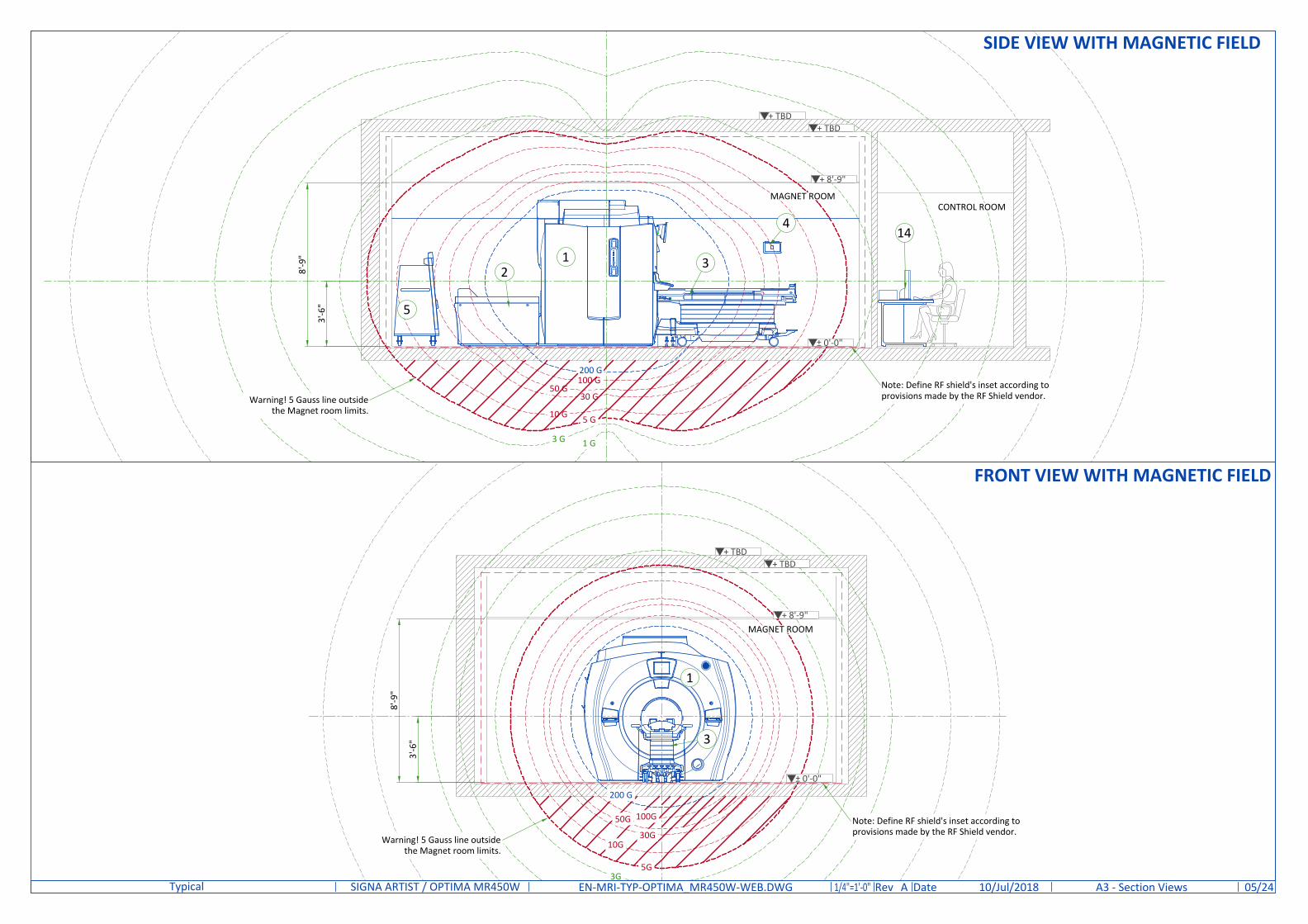
DateRev /24EN-MRI-TYP-OPTIMA_MR450W-WEB.DWG A 10/Jul/2018SIGNA ARTIST / OPTIMA MR450WTypical A3 - Section Views 05
SIDE VIEW WITH MAGNETIC FIELD
Note: Define RF shield's inset according toprovisions made by the RF Shield vendor.Warning! 5 Gauss line outside
the Magnet room limits.
MAGNET ROOMCONTROL ROOM
± 0'-0"
FRONT VIEW WITH MAGNETIC FIELD
5
4
32
1
1
3
14
MAGNET ROOM
Note: Define RF shield's inset according toprovisions made by the RF Shield vendor.
Warning! 5 Gauss line outsidethe Magnet room limits.
+ 8'-9"
+ TBD+ TBD
± 0'-0"
+ 8'-9"
+ TBD+ TBD
3'-6
"
3'-6
"
8'-9
"
8'-9
"

ISOGAUSS PLOTS
* The isogauss contour plots depicted on this drawing represent magnetic fringe fields resulting from the normaloperation of the magnet provided with the mr system. The actual magnetic field intensity at any point in thevicinity of the magnet when installed may vary from the contour plots due to factors such as the concentratingeffects of nearby ferrous objects ambient magnetic fields, including the earth's magnetic field. Therefore, thecontours shown are only approximations of actual field intensities found at a corresponding distance from themagnet's isocenter.
MAGNETIC PROXIMITY LIMITSGauss (mT) Limit Equipment
0.5 gauss (0.05mT) Nuclear camera
1 gauss (0.1mT) Positron Emission Tomography scanner, Linear Accelerator, Cyclotrons, Accurate measuring scale, Image intensifiers,Bone Densitometers, Video display (tube), CT scanner, Ultrasound, Lithotriptor, Electron microscope, Digital X-Ray
3 gauss (0.3mT) Power transformers, Main electrical distribution transformers5 gauss (0.5mT) Cardiac pacemakers, Neurostimulators, Biostimulation devices
10 gauss (1mT)Magnetic computer media, Line printers, Film processor, X-ray tubes, Emergency generators, Commercial laundryequipment, Food preparation area, Water cooling equipment, HVAC equipment, Major mechanical equipment room,Credit cards, watches, and clocks, Air conditioning equipment, Fuel storage tanks, Motors greater than 5 horsepower
50 gauss (5mT) Metal detector for screening, LCD panels, Telephones
No Limit Digital DetectorsThe customer must provide detail defining ferrous material below the magnet to the Project Manager so the GE Healthcare MR Siting andShielding team can review for compliance.
The following illustrations show the idealized static magnet isogauss plot lines. The actual field strength can be affected by Magnetic shielding,Earth's magnetic field, other magnetic fields and stationary or moving metal. This information must be used to evaluate potential siteinteraction of GE Healthcare equipment with other non-GE Healthcare equipment. Magnetic shielding can be installed to prevent interactionbetween the magnet and nearby sensitive devices. The GE Healthcare Project Manager of Installation (PMI) can work with the customer tocoordinate the magnetic shielding site evaluation. The customer is responsible for installation of all magnetic shielding.
STEEL MASS LIMITS TO MAGNET ISOCENTER (3.1 m x 3.1 m [10 ft. x 10 ft.] AREA UNDER MAGNET)Limits Of Steel Mass Distance From Magnet Isocenter Distance Below Top Surface Of Floor
kg/m² lbs/ft² mm in mm in
0 0 0 - 1143 0-45 0 - 76 0-3
9.8 2 1143 - 1194 45-47 76 - 127 3-5
14.7 3 1194 - 1321 47-52 127 - 254 5-10
39.2 8 1321 - 1397 52-55 254 - 330 10-13
98.0 20 1397+ 55+ 330+ 13+
0 10 20 30 40 50 60
0
0.05
0.1
0.15
0.2
0.25
0.3
0.35
0.4
FREQUENCY [Hz]
VIBRATION AMPLITUDE [m/s²]
Low Frequency Magnet Floor Vibration (Vibration Amplitude at Each Foot)
Acoustic and vibroacoustic information is provided for site planning and architectural design activities. It is thecustomer's responsibility to hire a qualified acoustic engineer for solutions to further attenuate this transmittednoise and vibration, if required. The actual room noise level may vary based on room design, optional equipment,and usage:
ACOUSTICS SPECIFICATIONS
FREQUENCY(Hz)
AMPLITUDE(m/s²)
2 0.05
10 0.05
20 0.35
30 0.35
35 0.2
50 0.2
Control Room: 62 dBAEquipment Room: 80 dBAMagnet Room: 127 dBA*(maximum sound pressure levelat magnet bore isocenter)
* Frequency: 20 Hz to 20kHz
SOUND PRESSURE SPECTRAL DISTRIBUTION
20 25 32 40 50 63 80 100
125
160
200
250
315
400
500
630
800
1000
1250
1600
2000
2500
3150
4000
5000
6300
8000
1000
0
1250
0
1600
0
0
5
SPL
(dBA
) - n
orm
alize
d
Frequency (1/3 Octave)
1/3 Band Relative SPL
10
15
20
25
30
DateRev /24EN-MRI-TYP-OPTIMA_MR450W-WEB.DWG A 10/Jul/2018SIGNA ARTIST / OPTIMA MR450WTypical A4 - Acoustic - Proximity Limits 06

MINIMUM MAGNET CEILING HEIGHT ( TOP VIEW )
1295[51 in]
1295[51 in]
MAGNETGEOMETRICISOCENTER
FRONT OF MAGNET
Shaded area indicates floor to ceiling minimum height of 2500 mm [98.42 in]. Special service procedures arerequired if ceiling height is between 2500 mm [98.42 in] and 2667 mm [105 in].
PENETRATION PANEL CABINET
An enclosure must be provided to restrict access to the PEN panels and for storage of excess interconnections. The PEN cabinet must have a mechanical locking mechanism to restrict access to the PEN panels PEN cabinet must allow free air exchange of 1200CFM (680 m³/hour) between the Magnet room and PEN
cabinet for MR system blowers. Airflow may be achieved through door louvers or other openings in the PENcabinet that meet all other PEN cabinet requirements
A closet service hatch must be provided if the room does not allow the PEN panel blower box removal path toremain completely outside the 200 Gauss line.NOTE: If the room size is sufficiently large so the SPW blower box can be removed without entering the 200 Gaussline, a closet service hatch is not required.
The closet service hatch must meet the following requirements: Must be located within the PEN cabinet on the RF wall allowing access to the Equipment room May be located anywhere within the PEN cabinet (between 254 [10 in] and 1524 mm [60 in] with unobstructed
pass-through) Must be minimum 508x508 mm [20x20 in] Must maintain RF shield integrity for all service access May use any design (quick disconnect RF panel, blanker panel, hinged door, etc.) as long as all other
requirements are met The closet service hatch removal must take less than 15 minutes (replacement must also take less than 15
minutes)
PENETRATION PANEL WITH SPW
OPENINGFOR SPW
OPENINGFOR PEN
RF common groundstud must be located
in this area
MAGNETROOM
FINISHEDWALL
PEN Cabinet
EQUIPMENTROOM
SPWSPW
PEN
MG6
Optional configurationwith SPW outside of thePEN cabinet
Frames
Minimum opening1300 [51.18 in](from equipmentroom)
1847 [73 in]
600[24 in]
1300[51 in]
60 [2 in]
1300 [51 in]
1600[63 in]
396 [16 in]
1600[63 in]
468[18 in]
135 [5 in]
468[18 in]
610[24 in]
EQUIPMENTROOM WALL
RF SHIELD
EQUIPMENTROOM WALL
PEN Panel Openings(Equipment Room Side)
Minimum opening in the wall:2.4m [94.5 in] HEIGHT x 1.3m [51.2 in] WIDTH
Standard* opening in the concrete wall:2.4m [94.5 in] HEIGHT x 1.6m [63 in] WIDTH
* with other filters (for lighting, sockets, injectors, ...)over the GE penetration panel
Maximum distance between PEN and SPW is 2743 [108]
SCALE 1:30
Frames supplied by GE
EQUIPMENT ROOM FLOOR
DateRev /24EN-MRI-TYP-OPTIMA_MR450W-WEB.DWG A 10/Jul/2018SIGNA ARTIST / OPTIMA MR450WTypical RF shielding 07

GLOBAL OPERATORS CABINET (GOC)
195 [7.7 in]
401 [15.8 in]755
[29.7 in]
326[12.8 in]
700[27.6 in]
377.5[14.9 in]
Center of Gravity
SCALE 1:10
TOP VIEW
FRONT VIEWSIDE VIEW
PENETRATION CABINET CLEARANCE
TOP VIEW
FRONT VIEW
SIDE VIEW
BlowerboxMAGNET ROOM
EQUIPMENT ROOM
EQUIPMENTROOM
MAGNET ROOM
50 ± 25mm from RF shield roomwall required for properconnection to penetration paneland cabinet airflow
Center of gravity
6 M12 x 1.75mmThread pitch mounting holes(3 on each side of cabinet)
Penetrationpanel
2 M12 x 1.75mmThread pitch mounting holes(front of cabinet)
Installationclearance
Airflow clearance
Installationclearance
Airflow clearance
Serviceclearance
Service clearance
Service clearance
Serviceclearance
Blower box
Serviceclearance
Cable droparea
51 [2 in]
102 [4 in]
600 [23.6 in]
381 [15 in]
381 [15 in]
440[17.3 in]
381 [15 in]
600[23.6 in]
381[15 in]
102[4 in]
100 [3.9 in]
400.5 [15.8 in]
166[6.5 in]
270 [10.6 in]
270[10.6 in]
359[14.1 in]
890[35 in]
914[36 in]
914[36 in]
914[36 in]
MAGNET ENCLOSURE
Center of gravity
Note:Center of gravity is approximate and includes the GE Healthcare supplied VibroAcoustic Dampening Kit, but does not include cryogens, gradientassembly, side mounted electronics, or enclosures.Enclosure dimensions are for reference only, NOT FOR SITE PLANNING USE.
32[1.3 in]
8[.3 in]
1838[72.4 in]
2466[97.1 in]
PATIENT TRANSPORT TABLE (PT)
SIDE VIEW
TOP VIEW2277
[89.6 in]
1500[59.1 in]
DateRev /24EN-MRI-TYP-OPTIMA_MR450W-WEB.DWG A 10/Jul/2018SIGNA ARTIST / OPTIMA MR450WTypical A6 - Equipment Details (1) 08

POWER, GRADIENT, RF CABINET (PGR)
Center of gravity
TOP VIEWA: Airflow clearanceB: Dolly installation clearanceC: Service clearanceD: Cable strain reliefE: Cable clearanceB
A
A
C
B
B
C
B
B B
D
E
FRONT VIEW SIDE VIEW
1480 [58.27 in]
806 [31.73 in]
561.8 [22.1 in]
499.3 [19.66 in]
914 [36 in]
381 [15 in]
381 [15 in]
872[34.33 in]
CRYOCOOLER COMPRESSOR ( CRY )
SCALE 1:20
A: Maintenance spaceB: Installation Clearance
Center of gravity
A
A
B
B
A
AB
AB
A, B
800[31.5 in]
232[9.1 in]
450[17.7 in]
276 [10.9 in]
103 [4.1 in]
153 [6 in]
450[17.7 in]
153 [6 in]
Input power terminal
Input power terminal
TOP VIEW
FRONT VIEW SIDE VIEW
381 [15 in]
872[34.3 in]
381[15 in]
1033[40.7 in]
440 [17.3 in]
445 [17.5 in]
872[34.3 in]
914[36 in]
610 [24 in]
152 [6 in]
610 [24 in]
TOP VIEW TOP VIEW
OR
monitormonitor
Cable Tray:bottom must be at least483mm [19.02in] abovecabinet
HEAT EXCHANGER CABINET ( HEC )
Additional service clearance required for Magnet Monitor.It can be installed on either side of the HEC.
A: Airflow clearanceB: Installation clearanceC: Service clearance
Center of gravity
A A A
A
B B
C
C
CC
C C C
Shipping without fluidShipping with fluid
FRONT VIEW SIDE VIEW
SECONDARY PENETRATION WALL (SPW)
Center of Gravity
FRONT VIEW SIDE VIEWTOP VIEW
SCALE 1:20
151 [6 in]
170 [6.7 in]
216[8.5 in]
448[17.6 in]
2 [.1 in]
914 [36 in]
914 [36 in]
914[36 in]
914[36 in]
321[12.6 in]
198[7.8 in]
MagnetRoom
EquipmentRoom
DateRev /24EN-MRI-TYP-OPTIMA_MR450W-WEB.DWG A 10/Jul/2018SIGNA ARTIST / OPTIMA MR450WTypical A7 - Equipment Details (2) 09

This is only a partial list of items required for delivery of the magnet. For a complete checklist refer to thepre-installation manual referenced on cover sheet.
24/7 chilled water and 480v power for shield/cryo cooler
24/7 120v power for the magnet monitor
Phone lines for magnet monitoring and emergency use
Magnet room exhaust fan
Cryogen venting (if roof hatch, completed within 24 hrs)
Magnet anchors installed and tested
CRITICAL ITEMS FOR MAGNET DELIVERYDELIVERY
STRAIGHT PATH(Rigging wheels required)
ROUTING The customer is solely liable for routing of components from dock to final site. GE must be able to move system components in or out with no need to uncrate or disassemble any of the
components. The entire passageway must be cleared, adequately lighted and free from dust. The floor and it surfacing must be able to withstand the live load of components and handling equipment. Floor surfacing must be continuous. The customer must protect any fragile flooring surfaces.
MINIMUM SPECIFICATIONS FOR MAGNET ROUTING Floor must be able to withstand a moving load of 5322 daN Height: 2.5 m [98.42in], width: 2.3 m [90.55in] Maximum slope: 30°
PATH WITH 90 DEGREE TURN
STORAGE CONDITIONS System components except the magnet should be stored in a cleaned
room: Temperature = -30 to 60°C [-22 to 140], relative humidity < 90% non
condensing. Material should not be stored for more than 90 days. The magnet will be delivered after GE validation of the site.
INSTALLATION AND DELIVERY ACCEPTANCE A survey of the site established by the customer and GE will make the
decision for the delivery time. This survey of the site (a form is made available by GE) is only to check if
the apparent conditions of the site allow the equipment to be delivered. If the site is not ready, GE can delay the delivery time.
Recommended opening for side (wall) delivery : 2300 mm [90.55in] (width) x 2500 mm [98.42in] (height)
FRONT VIEW OF MAGNET RIGHT SIDE VIEW OF MAGNET
2400[94.5 in]
1968[77.5 in]
2233[87.9 in]
2300[90.6 in]
2500[98.4 in]
GRADIENT COIL REPLACEMENT
Front view of the BRM Gradient Side view of the BRM Gradient
The weight bearing structure of the site should support any additional weight of the main replacement partsoccurring during maintenance of the magnet, throughout the whole lifecycle of the MR.
EQUIPMENTDIMENSIONS
LxWxH WEIGHT NOTEmm in kg lbs
Replacement BRM gradient coilassembly on a shipping cradle/cart 991x2536x1499 39x99.84x59 1449 3194
Initial gradient coil assembly is shipped installed in themagnet. Shipping/installation cart is used to install
re-placement coil assembly only.
2536[99.8 in]
992[39 in]
DateRev /24EN-MRI-TYP-OPTIMA_MR450W-WEB.DWG A 10/Jul/2018SIGNA ARTIST / OPTIMA MR450WTypical A8 - Delivery 10

VIBRATION TRANSMITTED THROUGH VIBROACOUSTIC MAT
12.5 16 20 25
31.5 40 50 63 80 100
125
160
200
250
315
400
500
630
800
1000
1250
1600
2000
2500
0
0.025Vibration [m/s²]
1/3 Octave Frequency [Hz]
0.05
0.075
0.1
0.125
0.15
0.175
0.2
0.225
0.25
00
EXCITATION FREQUENCY [Hz]
ACCELERATION g's (10¯⁶)
Abov
e am
bien
t bas
elin
e
MAGNET STEADY-STATE VIBRATION SPECIFICATIONS
VIBRATION SPECIFICATIONS
50
100
150
200
250
300
350
400
450
10 20 30 40 50
Excessive vibration can affect MR image quality. Vibration testing must be performed early in the site planningprocess to ensure vibration is minimized. Both steady state vibration (exhaust fans, air conditioners, pumps, etc.)and transient vibrations (traffic, pedestrians, door slamming, etc.) must be assessed.The Magnet cannot be directlyisolated from vibration. Any vibration issue must be resolved at the source.
Transient vibration levels above thespecified limits in the MR SiteVibration Test Guidelines must beanalyzed. Any transient vibrationthat causes vibration to exceed thesteady-state level must be mitigated.
All units that are wall mounted or wall supported are to be provided with supports where necessary. Wallsupports are to be supplied and installed by the customer or his contractors.
Dimensions are to finished surfaces of room.
Certain MR procedures require an extremely stable environment to achieve high resolution image quality.Vibration is known to introduce field instabilities into the imaging system. The vibration effects on imagequality can be minimized during the initial site planning of the MR suite by minimizing the vibrationenvironment. See PROXIMITY LIMITS, PATIENT TABLE DOCK ANCHOR MOUNTING REQUIREMENTS ANDVIBROACOUSTIC DAMPENING KIT details for additional information.
Standard steel studs, nails, screws, conduit, piping, drains and other hardware are acceptable if properlysecured. Any loose steel objects can be violently accelerated into the bore of the magnet. Careful thoughtshould be given to the selection of light fixtures, cabinets, wall decorations, etc. To minimize this potentialhazard. For safety, all removable items within the magnet room such as faucet handles, drain covers, switchbox cover plates, light fixture components, mounting screws, etc. Must be non-magnetic. If you have a specificquestion about material, bring it to the attention of your GE project manager of installations.
Floor levelness refer to MAGNET ROOM FLOOR SPECIFICATIONS DETAIL, this floor levelness requirement isimportant for accurate patient table docking.
Non-movable steel such as wall studs or hvac components will produce negligible effect on the active shieldmagnet.
Customers contractor must provide all penetrations in post tension floors.
Customers contractor must provide and install any non-standard anchoring. Documents for standardanchoring methods are included with GE equipment drawings for geographic areas that require suchdocumentation.
Customers contractor must provide and install hardware for "through the floor" anchoring and/or any bracingunder access floors. This contractor must also provide floor drilling that cannot be completed because of anobstruction encountered while drilling by the GE installer such as rebar etc.
Customers contractor to provide and install appropriate supports for the storage of excess cables.
It is the customer's responsibility to perform any floor or wall penetrations that may be required. Thecustomer is also responsible for ensuring that no subsurface utilities (e.g., electrical or any other form ofwiring, conduits, piping, duct work or structural supports (i.e. post tension cables or rebar)) will interfere orcome in contact with subsurface penetration operations (e.g. drilling and installation of anchors/screws)performed during the installation process. To ensure worker safety, GE installers will perform surfacepenetration operations only after the customer's validation and completion of the "GE surface penetrationpermit"
STRUCTURAL NOTES
DateRev /24EN-MRI-TYP-OPTIMA_MR450W-WEB.DWG A 10/Jul/2018SIGNA ARTIST / OPTIMA MR450WTypical S1 - Structural Notes 11

ITEM DESCRIPTION
(GE SUPPLIED / CONTRACTOR INSTALLED)
1 Vibroacoustic dampening kit (see floor structural detail)
2 Magnet curtain kit
(CONTRACTOR SUPPLIED & INSTALLED)
3 Patient table dock anchoring
4 Structural wall backing for Main Disconnect Panel
5 Structural wall backing for Magnet Rundown Unit
6 Structural wall backing for Main Bypass Panel
DateRev /24EN-MRI-TYP-OPTIMA_MR450W-WEB.DWG A 10/Jul/2018SIGNA ARTIST / OPTIMA MR450WTypical S2 - Structural Layout 12
MAGNET ROOMEQUIPMENT ROOM
CONTROL ROOM
LOCATED ELSEWHERE
4
5
3
1 1
1 1
5
6
2
9'-7
"
9'-4"11
'-6"
6'-4
"
9'-4"
LOCATED ELSEWHERE

CABLE CONCEALMENT
235[9 in]
960[38 in]
FRONT OF MAGNET
NOTE: THIS DRAWING IS TO BE USED ONLY AS A DESIGN INTENT DOCUMENT. REFER TO GE INSTALLATION MANUAL
FOR TRAY INSTALL. ACTUAL TRAY INSTALLATION MAY BE SITE DEPENDENT. THIS DRAWING NOT TO SCALE
CUSTOMER/CONTRACTOR INSTALLEDCABLE CONCEALMENT FRAMECUSTOMER/CONTRACTOR TO PROVIDEOPENING AND INSTALL FRAME.
MAGNETGEOMETRICISOCENTER
CABLE TRAYS
MAGNET ON VIBROACOUSTIC DAMPENING KIT "VIBROPAD"
VibroAcoustic Pad weight:8 kg [17 lbs] (each)NOT TO SCALE
4 x Ø38mm [1.5in] additionalmagnet holes for seismic zones
4 x Ø38mm [1.5in] holesfor magnet anchoring
Vibropad
1225 [48 in]
102 [4 in]
557 [22 in]
1114 [44 in]
338 [13 in]
390 [15 in]
268 [11 in]
Patient table dockanchor hole
MAGNET ROOM FLOOR SPECIFICATIONS
Floor levelness must be 3 mm between high and low spots in the rectangular area shown.
The finished floor must support the weight of all components (e.g., patient table, gradient coil replacement cart)throughout operation and service life.
6223[245 in]
2515[99 in]
PATIENT TABLE DOCK ANCHOR MOUNTING REQUIREMENTS
The RF Shield vendor must design and install the dock anchor bolt The dock anchor hole must be drilled after the Magnet is installed The dock anchor must not contact floor rebar or other structural steel The dock anchor must electrically contact the RF shield at point of entry The dock anchor properties must comply with requirements described in the Preinstallation Manual Chapter 3Section 5.4.4.
The RF shield vendor must perform a pull test on the anchor (equal to the clamping force).
NOT TO SCALE
FEMALE ANCHOR METHOD(CUTAWAY SIDE VIEW)
BOLTED METHOD(CUTAWAY SIDE VIEW)
1 Removable Anchor Rod (Male insert)2 Dock3 Clamp bracket4 Finished floor5 Filler Board or Grout6 RF Shield7 Conductive Fibrous Washer (RF seal)8 Concrete9 Female Anchor Insert
12345678987654321
DateRev /24EN-MRI-TYP-OPTIMA_MR450W-WEB.DWG A 10/Jul/2018SIGNA ARTIST / OPTIMA MR450WTypical S3 - Structural Details 13

ITEM DESCRIPTION
1 Cryogen vent (200mm [8"] O.D.)
2 Emergency exhaust vent - refer to magnet room vent requirements (position to be defined)
3 Pressure equalization vent - refer to magnet room vent requirements (position in ceiling to bedefined)
4 38mm [1.5"] NPT Male connectors, at 2.1m [82.67"] above floor, (2) 38mm [1.5"] copper lines(insulated) and (2) shut off valves. refer to chilled water block diagram
5 Closet must allow free air exchange of 400 CFM between magnet room and closet
6 Provide as needed - low pressure rubber multipurpose hose, inside dia. 1/2" working pressurerange: 250 to 499 PSI - refer to the manual city water back-up system detail
7 (2) 50mm [2"] I.D. High pressure hoses and (2) 50mm [2"] to 38mm [1.5"] Reducers
MECHANICAL/PLUMBING NOTES
All piping, fittings, supports, hoses, clamps, ventlation systems, etc. are to be supplied and installedby the customer or his contractors.For complete design and requirements, specifications and guidelines refer to the pre-installationmanual: system cooling, cryogen venting, waveguides and exhaust venting.An emergency water cooling back-up supply is recommended for continuous cryogen compressoroperation. if using an open loop back-up design, ensure a drain is provided. please refer to thepre-install manual for optional back-up coolant supply requirements
DateRev /24EN-MRI-TYP-OPTIMA_MR450W-WEB.DWG A 10/Jul/2018SIGNA ARTIST / OPTIMA MR450WTypical M1 - Mechanical Layout 14
MAGNET ROOM
EQUIPMENT ROOM
CONTROL ROOM
LOCATED ELSEWHERE
1
13.7
6±.25
16.2±.25
23
4
5
6
7
4
LOCATED ELSEWHERE9'-4"
11'-6
"

TEMPERATURE AND HUMIDITY SPECIFICATIONS
IN-USE CONDITIONS
NOTEIn case of using air conditioning systems or chilled water piping that have a risk of water leakage it is recommended not to install it aboveelectric equipment or to take measures to protect the equipment from dropping water.
AIR EXCHANGEAccording to local standards.
NOTEMaximum ambient temperature for the Equipment room at inlet is derated by 1°C per 300 m (984 ft) above 2000 m (6562 ft) (not to exceed2600 m [8530 ft]).
MAGNET ROOM CONTROL ROOM EQUIPMENT ROOM
Temperature
Range Range Range
15 to 21°C 15 to 32°C 15 to 32°C
59 to 69.8°F 59 to 89.6°F 59 to 89.6°F
Temperature gradient± 3°C/h ± 3°C/h ± 3°C/h
± 5°F/h ± 5°F/h ± 5°F/hRelative humidity (1) 30% to 60% 30% to 70% 30% to 70%Humidity gradient ≤ 5%/h ≤ 5%/h ≤ 5%/h
System heat dissipation
Stand by Average Max Stand by Average Max Stand by Average Max
1.01kW 1.8kW 3.15kW 1.46kW 5.79kW 6.87kW 13.05kW
3450 btu 6142 btu 10748 btu 4947 btu 19769 btu 23225 btu 44523 btu
HEAT DISSIPATION DETAILS
DESCRIPTION ROOMIDLE AVERAGE MAX
W btu W btu W btuMagnet (MAG) and Patient Table (PT) Magnet 561 1915 1200 4095 2400 8189Blower Box (MG6) Magnet 450 1535 450 1535 450 1535Penetration Panel Cabinet (PEN) Magnet 0 0 150 512 300 1024
Penetration Panel Cabinet (PEN) Equipment 1568 5349 1568 5349 3135 10697
Secondary Penetration Wall (SPW) Magnet/Equipment 0Main Disconnect Panel (MDP) Equipment 132 450 132 450 264 901
Power, Gradient, RF Cabinet (PGR) Equipment 2500 8530 3068 10470 6137 20940
Crycooler Compressor (CRY) Equipment 500 1706 500 1706 500 1706Heat Exchanger Cabinet (HEC) Equipment 500 1706 500 1706 1000 3412Magnet Monitor (MON) Equipment 240 819 240 819 240 819Operator Workspace equipment (OW) Control 1450 4947 1450 4947 1450 4947
OPTIONS
BrainWave HW Lite Cabinet (BW) Equipment 685 2337 685 2337 685 2337BrainWave HW Lite Cabinet with Options Equipment 815 2781 815 2781 815 2781CADstream Equipment 350 1209 799 2725 1773 6049MR Elastography (MRE) Equipment 141 480 141 480 141 480
MAGNET ROOM EXHAUST FAN SCHEMATICVent to outside
environment
Exhaust Fan
To FacilityAir Handler
AC Power (rated as requiredfor operation of MotorizedDamper and Exhaust Fan)Ground secondary of lowvoltage transformer to RFRoom Common Ground Stud
RF Shield
Dielectric Isolator
Room ceiling Motorized Damper
Exhaust Intake Vent
MAGNET ROOM CONTROL ROOM
RF Filter
ON/OFFManualfan switches inparallel
Ductwork
Ductwork
MAGNET ROOM VENTING REQUIREMENTS
HVAC VENT REQUIREMENTS HVAC vendor must comply with Magnet room temperature and humidity specifications and RF shielding specifications. RF Shield vendor must install open pipe or honeycomb HVAC waveguides. All serviceable parts in the Magnet room (e.g.: diffusers) must be non-ferrous. Waveguides must be non-ferrous and electrically isolated. Incoming air must contain at least 5% air from outside the Magnet room (inside or outside the facility) to displace residual helium.
EMERGENCY EXHAUST VENT REQUIREMENT Exhaust vent system is supplied by the customer. All items within the RF enclosure must be non-ferrous. The exhaust vent system must be tested and operational before the magnet is installed. The exhaust intake vent must be located near the magnet cryogenic vent at the highest point on the finished or drop ceiling. The Magnet room exhaust fan and exhaust intake vent must have a capacity of at least 34 m³/min (1200 CFM) with a minimum of 12 room
air exchanges per hour. The exhaust fan must be placed outside the RF shielding located outside 10 gauss (1mT) and with appropriate waveguide. The system must have a manual exhaust fan switch near the Operator Workspace (OW) and in the Magnet room near the door (the
switches must be connected in parallel). All system components must be accessible for customer inspection, cleaning and maintenance
PRESSURE EQUALIZATION VENT REQUIREMENT A pressure equalizing vent is required in the magnet room ceiling or in the wall, at the highest point possible. The vent minimum size must be 610 mm x 610 mm (24 in x 24 in) or equivalent area. The pressure equalization vent must be located so any Helium gas is not vented into occupied areas.
Note: Location may affect acoustic noise transmission into occupied spaces.
DateRev /24EN-MRI-TYP-OPTIMA_MR450W-WEB.DWG A 10/Jul/2018SIGNA ARTIST / OPTIMA MR450WTypical M2 - HVAC-Venting 15
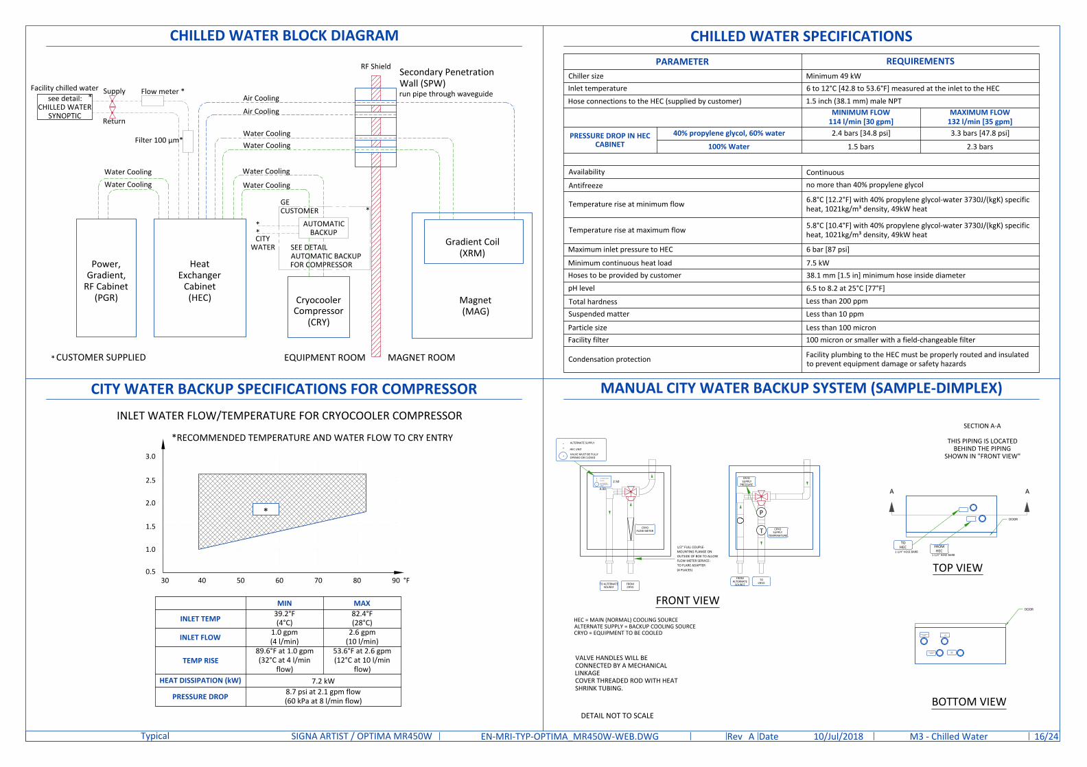
INLET WATER FLOW/TEMPERATURE FOR CRYOCOOLER COMPRESSOR
*RECOMMENDED TEMPERATURE AND WATER FLOW TO CRY ENTRY
CITY WATER BACKUP SPECIFICATIONS FOR COMPRESSOR
0.5
1.0
1.5
2.0
2.5
3.0
30 40 50 60 70 9080 °F
*
MIN MAX
INLET TEMP 39.2°F(4°C)
82.4°F(28°C)
INLET FLOW1.0 gpm(4 l/min)
2.6 gpm(10 l/min)
TEMP RISE89.6°F at 1.0 gpm(32°C at 4 l/min
flow)
53.6°F at 2.6 gpm(12°C at 10 l/min
flow)HEAT DISSIPATION (kW) 7.2 kW
PRESSURE DROP 8.7 psi at 2.1 gpm flow(60 kPa at 8 l/min flow)
TO ALTERNATESOURCE
FROMCRYO
TOHEC
FROMALTERNATE
SOURCE
TOCRYO
FROMHEC
T
P
TOP VIEW
BOTTOM VIEW
A A
FRONT VIEW
SECTION A-A
THIS PIPING IS LOCATEDBEHIND THE PIPING
SHOWN IN "FRONT VIEW"
VALVE HANDLES WILL BECONNECTED BY A MECHANICALLINKAGECOVER THREADED ROD WITH HEATSHRINK TUBING.
1-1/4" HOSE BARB1/2" FULL COUPLE-MOUNTING FLANGE ONOUTSIDE OF BOX TO ALLOWFLOW METER SERVICE-TO FLARE ADAPTER(4 PLACES)
DOOR
TO ALTERNATESOURCE
FROMCRYO
FROM ALTERNATESOURCE
TOCRYO
ALTERNATE SUPPLY
HEC UNIT
CRYO SUPPLY
PRESSURE
CRYOSUPPLY
TEMPERATURE
HEC = MAIN (NORMAL) COOLING SOURCEALTERNATE SUPPLY = BACKUP COOLING SOURCECRYO = EQUIPMENT TO BE COOLED
VALVE MUST BE FULLYOPENED OR CLOSED
ALTERNATE SUPPLY
HEC UNIT
VALVE MUST BEFULLY OPENED ORCLOSED
2.50
4.00
1-1/4" HOSE BARB
CRYOFLOW METER
DOOR
MANUAL CITY WATER BACKUP SYSTEM (SAMPLE-DIMPLEX)
DETAIL NOT TO SCALE
CHILLED WATER BLOCK DIAGRAM
Power,Gradient,
RF Cabinet(PGR)
HeatExchanger
Cabinet(HEC) Cryocooler
Compressor(CRY)
MAGNET ROOMEQUIPMENT ROOM
Air Cooling
Air Cooling
Secondary PenetrationWall (SPW)run pipe through waveguide
CITYWATER
AUTOMATICBACKUP
SEE DETAILAUTOMATIC BACKUPFOR COMPRESSOR
GECUSTOMER
Water CoolingWater Cooling
*
**
*
CUSTOMER SUPPLIED
Water Cooling
Water Cooling
Water CoolingWater Cooling
Magnet(MAG)
Gradient Coil(XRM)
RF Shield
see detail:CHILLED WATER
SYNOPTIC
*
Return
Supply Flow meter *
Filter 100 µm*
Facility chilled water
PARAMETER REQUIREMENTSChiller size Minimum 49 kWInlet temperature 6 to 12°C [42.8 to 53.6°F] measured at the inlet to the HECHose connections to the HEC (supplied by customer) 1.5 inch (38.1 mm) male NPT
MINIMUM FLOW114 l/min [30 gpm]
MAXIMUM FLOW132 l/min [35 gpm]
PRESSURE DROP IN HECCABINET
40% propylene glycol, 60% water 2.4 bars [34.8 psi] 3.3 bars [47.8 psi]
100% Water 1.5 bars 2.3 bars
Availability Continuous
Antifreeze no more than 40% propylene glycol
Temperature rise at minimum flow 6.8°C [12.2°F] with 40% propylene glycol-water 3730J/(kgK) specificheat, 1021kg/m³ density, 49kW heat
Temperature rise at maximum flow 5.8°C [10.4°F] with 40% propylene glycol-water 3730J/(kgK) specificheat, 1021kg/m³ density, 49kW heat
Maximum inlet pressure to HEC 6 bar [87 psi]
Minimum continuous heat load 7.5 kWHoses to be provided by customer 38.1 mm [1.5 in] minimum hose inside diameterpH level 6.5 to 8.2 at 25°C [77°F]
Total hardness Less than 200 ppm
Suspended matter Less than 10 ppm
Particle size Less than 100 micronFacility filter 100 micron or smaller with a field-changeable filter
Condensation protection Facility plumbing to the HEC must be properly routed and insulatedto prevent equipment damage or safety hazards
CHILLED WATER SPECIFICATIONS
DateRev /24EN-MRI-TYP-OPTIMA_MR450W-WEB.DWG A 10/Jul/2018SIGNA ARTIST / OPTIMA MR450WTypical M3 - Chilled Water 16

MAGNET CRYOGENIC VENT SYSTEM PRESSURE DROP MATRIX
Notes1. Elbows with angles greater than 90 deg must not be used2. Data in Table is based on the following facts and assumptions:
a. Initial flow conditions at magnet interfaceb. EM energy (13MJ) is dumped to He during quench and rises He temperature to 10 Kelvinc. Gas temperature starting at 10 Kelvin and increase with length determined by thermal energy balanced. 90% He is assumed to be evacuated within 30 sec. None left after quench.e. Absolute roughness is assumed to be 0.25 mm.f. R/D = 1.0 for standard sweep elbows, R/D = 1.5 for long sweep elbows where D = outer diameter of pipe; R
= radius of bend3. The total pressure drop of the entire cryogenic vent system must be less than 17 psi (117.2 kPa). The calculationstarts at the magnet vent interface and ends at the termination point outside the building.
Outerdia.of
pipe(D)
Distance ofvent systemcomponent
from magnet
Pressuredrop forstraightpipe
Stdsweep 45°
elbow
Stdsweep 90°
elbow
Longsweep45° elbow
Longsweep 90°
elbow
ft m psi/ft kPa/m psi kPa psi kPa psi kPa psi kPa
8 in.(200mm)
0-20 0-6.1 0.10 2.26 1.10 7.58 2.06 14.20 0.55 3.79 1.03 7.10
20-40 6.1-12.2 0.21 4.75 2.10 14.48 3.70 25.51 1.03 7.10 1.85 12.76
40-60 12.2-18.3 0.30 6.79 2.88 19.86 5.21 35.92 1.44 9.93 2.60 17.92
60-80 18.3-24.4 0.38 8.60 3.70 25.51 6.71 46.27 1.85 12.76 3.36 23.17
80-100 24.4-30.5 0.47 10.63 4.52 31.17 8.22 56.68 2.26 15.58 4.11 28.34
10 in.(250mm)
0-20 0-6.1 0.03 0.68 0.55 3.79 0.82 5.65 0.27 1.86 0.04 2.83
20-40 6.1-12.2 0.07 1.58 0.82 5.65 1.51 10.41 0.41 2.83 0.75 5.17
40-60 12.2-18.3 0.10 2.26 1.23 8.48 2.19 15.10 0.62 4.27 1.10 7.58
60-80 18.3-24.4 0.12 2.71 1.51 10.41 2.74 18.89 0.75 5.17 1.37 9.45
80-100 24.4-30.5 0.16 3.62 1.92 13.24 3.43 23.65 0.96 6.62 1.71 11.79
12 in.(300mm)
0-20 0-6.1 0.013 0.29 0.27 1.86 0.41 2.83 0.14 0.97 0.21 1.45
20-40 6.1-12.2 0.027 0.61 0.41 2.83 0.82 5.65 0.21 1.45 0.41 2.83
40-60 12.2-18.3 0.041 0.93 0.55 3.79 1.10 7.58 0.27 1.86 0.55 3.79
60-80 18.3-24.4 0.054 1.22 0.69 4.76 1.37 9.45 0.34 2.34 0.69 4.76
80-100 24.4-30.5 0.069 1.56 0.96 6.62 1.51 10.41 0.48 3.31 0.75 5.17
14 in.(350mm)
0-20 0-6.1 0.008 0.055 0.20 1.3800 0.301 2.08 0.102 0.70 0.15 1.03
20-40 6.1-12.2 0.017 0.12 0.30 2.07 0.602 4.15 0.154 1.06 0.30 2.07
40-60 12.2-18.3 0.026 0.18 0.40 2.76 0.808 5.57 0.198 1.37 0.40 2.76
60-80 18.3-24.4 0.034 0.23 0.51 3.52 1.01 6.96 0.250 1.72 0.51 3.52
80-100 24.4-30.5 0.043 0.30 0.71 4.90 1.11 7.65 0.353 2.43 0.55 3.79
16 in.(400mm)
0-20 0-6.1 0.0053 0.037 0.153 1.05 0.230 1.59 0.078 0.54 0.115 0.79
20-40 6.1-12.2 0.013 0.09 0.229 1.58 0.460 3.17 0.188 0.81 0.229 1.58
40-60 12.2-18.3 0.020 0.14 0.306 2.11 0.618 4.26 0.152 1.05 0.306 2.11
60-80 18.3-24.4 0.026 0.18 0.390 2.69 0.773 5.33 0.191 1.32 0.390 2.69
80-100 24.4-30.5 0.033 0.23 0.543 3.74 0.850 5.86 0.270 1.86 0.421 2.90
DateRev /24EN-MRI-TYP-OPTIMA_MR450W-WEB.DWG A 10/Jul/2018SIGNA ARTIST / OPTIMA MR450WTypical M4 - Mechanical Details 17

TYPICAL CRYOGENIC VENT PIPE DETAIL
MAGNET VENT ADAPTERDo not remove or modify thevent adaptor bolted to themagnet.
VENT PIPE610 mm [24 in], may be cut to aminimum of 100 mm [4 in].
VENTGLASCONNECTOR
WAVEGUIDE
Additional pipe/tubing
Bird screen 12.7 mm[0.5 in] mesh
DIELECTRICBREAK
CRYOGENIC VENTING ( EXTERIOR )
GROUND
VENT CAP(customer supplied)
OUTSIDE WALL
ROOF
VENT CAP(customersupplied)
NOT TO SCALE
EXHAUST AREA6.1m x 4.6m[20ft x 15ft] (LxW)
EXHAUST AREA6.1m x 4.6m[20ft x 15ft] (LxW)
4600mm [181.1in]
Exclusion area
Warning sign
914.
4mm
[36i
n]36
57.6
mm
[144
in]
TYPICAL CRYOGEN SIDE WALL EXIT WITH LONG SWEEP ELBOWKEY COMPONENTS : RF waveguide extended from wall to magnet adapter Must be all same material and all welded Support system must withstand 8229 N [1850 lbs] GE ventglas must be installed in vertical section directly over magnet
RF WAVEGUIDE EXTENDED
Mesh bird screen
rigid support38 mm [1.50 in]insulation
203mm [8 in]ventglas outsideRF room
25.4±6.35 [1 in±.2 in]
OUTSIDE
DateRev /24EN-MRI-TYP-OPTIMA_MR450W-WEB.DWG A 10/Jul/2018SIGNA ARTIST / OPTIMA MR450WTypical M5 - Cryogenics 18

ELECTRICAL NOTES
All junction boxes, conduit, duct, duct dividers, switches, circuit breakers, cable tray, etc., are to be suppliedand installed by customers electrical contractor.
Conduit and duct runs shall have sweep radius bends Conduits and duct above ceiling or below finished floor must be installed as near to ceiling or floor as possible
to reduce run length. Ceiling mounted junction boxes illustrated on this plan must be installed flush with finished ceiling. All ductwork must meet the following requirements:
1.Ductwork shall be metal with dividers and have removable, accessible covers.2.Ductwork shall be certified/rated for electrical power purposes.3.Ductwork shall be electrically and mechanically bonded together in an approved manner.4.PVC as a substitute must be used in accordance with all local and national codes. All openings in access flooring are to be cut out and finished off with grommet material by the customers
contractor. General contractor to insert pull cords for all cable run conduits between the equipment room and the
operators control room. 10 foot pigtails at all junction points. Grounding is critical to equipment function and patient safety. Site must conform to wiring specifications
shown on this plan.
1. All wires specified shall be copper stranded, flexible, thermo-plastic, color coded, cut 10 foot long at outletboxes, duct termination points or stubbed conduit ends. All conductors, power, signal and ground, must berun in a conduit or duct system. Electrical contractor shall ring out and tag all wires at both ends. Wire runsmust be continuous copper stranded and free from splices.
1.1. Aluminum or solid wires are not allowed.2. Wire sizes given are for use of equipment. Larger sizes may be required by local codes.3. It is recommended that all wires be color coded, as required in accordance with national and local electrical
codes.4. Conduit sizes shall be verified by the architect, electrical engineer or contractor, in accordance with local or
national codes.5. Convenience outlets are not illustrated. Their number and location are to be specified by others. Locate at
least one convenience outlet close to the system control, the power distritbution unit and one on each wall ofthe procedure room. Use hospital approved outlet or equivalent.
6. General room illumination is not illustrated. Caution should be taken to avoid excessive heat from overheadspotlights. Damage can occur to ceiling mounting components and wiring if high wattage bulbs are used.Recommend low wattage bulbs no higher than 75 watts and use dimmer controls (except mr). Do not mountlights directly above areas where ceiling mounted accessories will be parked.
7. Routing of cable ductwork, conduits, etc., must run direct as possible otherwise may result in the need forgreater than standard cable lengths (refer to the interconnection diagram for maximum usable lengths pointto point).
8. Conduit turns to have large, sweeping bends with minimum radius in accordance with national and localelectrical codes.
9. A special grounding system is required in all procedure rooms by some national and local codes. It isrecommended in areas where patients might be examined or treated under present, future, or emergencyconditions. Consult the governing electrical code and confer with appropriate customer administrativepersonnel to determine the areas requiring this type of grounding system.
10. The maximum point to point distances illustrated on this drawing must not be exceeded.11. Physical connection of primary power to GE equipment is to be made by customers electrical contractor with
the supervision of a GE representative. The GE representative would be required to identify the physicalconnection location, and insure proper handling of GE equipment.
12. GEHC conducts power audits to verify quality of power being delivered to the system. The customer'selectrical contractor is required to be available to support this activity.
CONNECTIVITY REQUIREMENTS
Broadband Connections are necessary during the installation process and going forward to ensure full supportfrom the Engineering Teams for the customers system. Maximum performance and availability for the customerssystem is maintained and closely monitored during the lifetime of the system. Proactive and reactive maintenanceis available utilising the wide range of digital tools using the connectivity solutions listed below:
Site-to-Site VPN/GE Solution Site-to-Site VPN/Customer Solution Connection through Dedicated Service Network Internet Access - connectivity for InSite 2.0
The requirements for these connectivity solutions are explained in the broadband solutions catalogue (separatedocument).
LIGHTING REQUIREMENTS
All lighting fixtures and associated components must meet all RF shielded room and RF groundingrequirements (e.g., track lighting is not recommended due to possible RF noise).
All lighting must use direct current (the DC must have less than 5% ripple). 300 lux must be provided at the front of the magnet for patient access and above the magnet for servicing. Fluorescent lighting must not be used in the magnet room. Lighting must be adjusted using a discrete switch or a variable DC lighting controller. Scr dimmers or rheostats must not be used. DC led lighting may be used if the power source is located outside the magnet room RF. Battery chargers (e.g., used for emergency lighting) must be located outside the magnet RF room. Short filament length bulbs are recommended. Linear lamps are not recommended due to the high burnout rate.
DateRev /24EN-MRI-TYP-OPTIMA_MR450W-WEB.DWG A 10/Jul/2018SIGNA ARTIST / OPTIMA MR450WTypical E1 - Electrical Notes 19

A
B
D
C
Additional Conduit Runs(Contractor Supplied and Installed)
From To Qty Size (in) Size (mm)
Main Disconnect Panel
Power, Gradient, RF cabinet 1 as Req'd
Heat Exchange Cabinet 1 as Req'd
System emergency off 1 1/2 16System emergency off Secondary Penetration Wall 1 1/2 16
Door Switch Power, Gradient, RF cabinet 1 3/4 20System emergency off Secondary Penetration Wall 1 3/4 20
Magnet Rundown UnitMagnet 1 1 25
RF filter 1 as Req'd
RF filter 120-V 1Ø Power 1 as Req'd
Room Light RF filter 1 as Req'd
RF filter Facility emergency power 1 as Req'd
Main Bypass PanelMain Disconnect Panel 1 as Req'd
UPS 2 as Req'd
Facility power as Req'd
ChillerRemote graphic display 1 3/4 20Facility power 1 as Req'd
TV CameraWaveguide or RF filter
1 1 25
TV Monitor 1 1 25Injector control unit
Waveguide or RF filter
1 2 1/2 70Injector head 1 as Req'd
Integrated Battery ChargingUnit 1 as Req'd
ITEM QTY DESCRIPTION(CONTRACTOR SUPPLIED & INSTALLED)
1 Cable ladder 450mm x 150mm [18" x 6"]
2 Non-ferrous cable ladder 450mm x 150mm [18" x 6"]
3 Box above ceiling size per local code
4 150mm x 100mm [6" x 3 1/2"] Surface wall duct
5 Magnet rundown unit/remote magnet rundown unit
6 Main disconnect panel
7 Main bypass panel
8 One 50mm [2"] cnd above ceiling
9 One 75mm [3"] cnd above ceiling
10 One 65mm [2 1/2"] cnd above ceiling
ITEM QTY Outlet Legend for GE Equipment
System emergency off (SEO), (recommended height 1.2m [48"] above floor)
Door interlock switch (needed only if required by state/local codes)Emergency exhaust fan switch 1.2m [48"] height recommended)
Duplex hospital grade, dedicated wall outlet 120-v, single phase power
Network outletDedicated telephone lines/network connectionDuplex hospital grade, dedicated outlet 120-v emergency, single phase power, 15a
Duplex hospital grade, dedicated outlet 120-v, single phase outlet routed through RFfilter
DateRev /24EN-MRI-TYP-OPTIMA_MR450W-WEB.DWG A 10/Jul/2018SIGNA ARTIST / OPTIMA MR450WTypical E2 - Electrical Layout 20
MAGNET ROOM
EQUIPMENT ROOM
CONTROL ROOM
LOCATED ELSEWHERE
1
2
3
4
5
6
7
89
1
2
10
45
LOCATED ELSEWHERE
0'-3"
5'-1"9'-4" 6'
-4"
11'-6
"9'-4"
9'-7
"

C
A B
D
DateRev /24EN-MRI-TYP-OPTIMA_MR450W-WEB.DWG A 10/Jul/2018SIGNA ARTIST / OPTIMA MR450WTypical E3 - Electrical Elevations 21
MAGNET ROOM
EQUIPMENT ROOM
± 0'-0"
+ 8'-9"
+ TBD+ TBD
6
1
MAX
. 10'
-8"
MIN
0'-1
0"
44
3
EQUIPMENT ROOM
CONTROL ROOM
10'-8
"M
AXIM
UM
5'-4
"
5'-4
"
55
2
± 0'-0"
+ TBD+ TBD
± 0'-0"
+ TBD+ TBD
± 0'-0"
+ TBD+ TBD
+ TBD
+ TBD
+ TBD
6
5'-5
"
0'-7
"

CABLE WAYS IN EQUIPMENT ROOM
CABLE LADDER
CablesWater and air pipes
Cable trays detail side-by-side: (2x450mm [18in])
450 [18 in]
SIDE-BY-SIDE
102 [4 in]
PGRCabinet
CABLE TRAY
CABLE WAY TO PENETRATION PANEL
SIDE VIEWTOP VIEW
SecondaryPenetration Wall(SPW)
330 [13 in]Min bend radius
Gradient cableclamps
Cable Way
FINISHED FLOOR
FINISHED CEILING
RF Shield
CableWay
Penetrationpanel closet
SecondaryPenetration Wall(SPW)
The end of the cable way must be containedin the pen closet (cables must not restdirectly on the wall opening)
330 [13 in]Min bend radius
Gradient cableclamps
CABLE WAY TO PENETRATION PANEL REQUIREMENTS IN THE EXAM ROOM SIDE VIEW
200[8 in]
330[13 in]
Min 500 [20 in]
330 [13 in]
200 [8 in]
CABLE WAYS REQUIREMENTS IN MAGNET ROOM
330 [13 in]Min bend radius
1 - Ceiling2 - Finished Floor3 - Magnet isocenter. Gradient cables must be centered on magnet isocenter.4 - Minimum cable tray height required at back of Magnet: 2581 mm [101.5 in]. Tray height may be lower at other points to avoid obstructions.5 - Maximum height from floor to top of tray (anywhere in Magnet room): 3251 mm [128 in].6 - Minimum distance from top of cable tray to ceiling or other obstruction: 254 mm [10 in].7 - Tray end to isocenter: 1099 ±12 mm [43.25 ±0.5 in].8 - Other cable termination to isocenter: 718 ±12 mm [28.25 ±0.5 in].9 - Minimum distance between trays: 12 mm [0.5 in].10 - Non-ferrous cable support11 - Distance from isocenter to edge of right cable tray 60mm [2.36 in].
Cable Tray Requirements (Side-By-Side)
1
7
6
4
3
10
8
9
5
11
DateRev /24EN-MRI-TYP-OPTIMA_MR450W-WEB.DWG A 10/Jul/2018SIGNA ARTIST / OPTIMA MR450WTypical E4 - Electrical Details 22

POWER DISTRIBUTION
3-No. 8 Black1-No. 8 Green
Cable SUPPLIED BY CUSTOMER
Equipment SUPPLIED BY GE
Equipment SUPPLIED BYCUSTOMER
Cable SUPPLIED BY GE
3-No. 1/0 Black1-No. 1/0 Green
3-No. 12 Black1-No. 12 Green
GND BUSS BAR
{
NC
AUXILLIARY BOARD
POWER DISTRIBUTION
{
L1
L2
L3
G
NC
RF SHIELD
RUN E4002
RUN E3030 RUN M3030
CB MDP200 AMPS150 AMPS50 AMPS
123
1-No. 10
CRYOCOOLERCOMPRESSOR
(CRY)
HEAT EXCHANGERCABINET (HEC)
TO PDU TERMINALSTRIP LOCATED ONTOP OF PGR
POWER DISTRIBUTION UNIT(PDU)
POWER CABINET (PGR)
MAIN DISCONNECT PANEL (MDP)
CB#1 CB#2
UV TRIP
NEUTRAL
GROUND
NEUTRAL MUSTBE TERMINATEDINSIDE THE MDP
CB#3
FUSES
GNDTO TERMINALSTRIP LOCATEDON THE TOPOF HEC
EMERGENCY OFFDC SAFETY
CIRCUT WITHBATTERY BACKUP
120VACAUTO
RESTARTCONTROLCIRCUIT
EQUIPMENT ROOM"EMERGENCY OFF"
BUTTON (E02)
PENETRATION CABINET(PEN)
SECONDARYPENETRATIONWALL (SPW)
MAGNET ROOM"EMERGENCYOFF" BUTTON
(E01)
RF COMMON GROUND STUD(DO NOT GROUND RF ROOMTO ANY POINT OTHER THAN
THE PDU)
NEUTRALBUSS BAR
G/PEBUSSBAR
NOTE: THE HEAT EXCHANGER CABINET (HEC) PROVIDES POWER TO THE CRYOCOOLER COMPRESSOR (CRY) WHICH MUST OPERATE 24 HOURS PER DAY, 7
DAYS PER WEEK TO MAXIMIZE PROPER UNINTERRUPTED MAGNET OPERATION.
RUNS E3030, M0009, M3030 AND E4002 ARE GE SUPPLIED CABLES. ALL OTHER WIRING IS CUSTOMER SUPPLIED.
TWO REMOTE FLUSH WALL MOUNTED EMERGENCY OFF BUTTONS ARE SUPPLIED WITH THE MDP.
MDP PROVIDES CIRCUIT BREAKERS FOR PDU (LOCATED IN THE POWER CABINET (PGR)) AND THE HEAT EXCHANGER CABINET (HEC).
ALL MDP OUTPUT CIRCUITS DROP OUT ON LOSS OF POWER. THE HEC CIRCUIT WILL AUTOMATICALLY RESTART UPON RESTORATION OF POWER.EMERGENCY OFF LOCKS OUT ALL CONTRACTORS.
GE MDP SHORT CIRCUIT CURRENT RATING IS 25,000 AMPERES AT 480 VAC.
GE MDP IS UL AND cUL LABELED.
ALL CIRCUITS REQUIRE GROUND WIRES.
THE WIRE SIZE FOR THE EMERGENCY-OFF CIRCUIT IS 12-22 AWG CUSTOMER SUPPLIED
POWER DISTRIBUTION
RUN M0009
GE DIGITAL
BATTERYCABINET
BYPASS PANELGE MAINTENANCE
CONTROL
UPS INPUT
UPSSYSTEM
ENERGY
150 A
250 A
300 A
250 A
4-Black1-Green
4-Black1-Green
4-Black1-Green
3-Black1-Green
NOTES:1) Full system UPS will generate EMI fields,customer should be cognizant of location ofsensitive equipment in the immediate areaadjoining the UPS system2) Customer/Contractor responsible to completePre-Start Up checklist, including connection ofbatteries to UPS system prior to scheduledstartup.
480Y (277V) BUILDING POWER300 AMP MINIMUM 3 PHASE, 4W + G REQ'D
MAIN LUGS: (1) #6-600 KCMIL PER PHASE
2 SPACES, EITHER15-150A OR 70-250AMAX. FOR OPTIONAL
LOADS
UPSOUTPUT
UPSOUTPUT
CONTROL
UPS INPUT
POWER REQUIREMENTS
SPECIFICATIONS OF MAIN POWER INPUT
CABLES
Power and cable installation must comply with the distribution diagram. Size of the Main power input cable is determined by the customer, taking its length and admissible voltage
drops into consideration. All cables must be isolated and flexible, cable color codes must comply with standards for electrical installation. The cables from signaling and remote control (Y,Emergency Off Buttons,L...) will go to Main Panel with a pigtail
length of 1.5m [60in], and will be connected during installation. Each conductor will be identified and isolated (screw connector).
GROUND SYSTEM
The equipotential link will be by means of an equipotential bar. The grounding point of MDP is directly connected to the building's ground by an isolated copper cable. The impedance of the earth bar should be less than or equal to 2 ohms.
Power input must be separated from any others which may generate transients (elevators, air conditioning,radiology rooms equipped with high speed film changers...).
Total harmonic distortion less than 2.5%. Phase imbalance must not exceed 2%.
SPECIFICATIONS OF BACK-UP POWER SUPPLY
POWER SUPPLY 380/400/415/480V ±10%, THREE-PHASE + N + GFREQUENCIES 50/60Hz ± 3HzPOWER FACTOR 0.9MAXIMUM INPUT POWER (5 sec MAX) 123kVAINSTALLED LOAD 99kVASTAND-BY POWER < 17kVA
FOR MAGNET MONITORPOWER INPUT EMERGENCY POWER SUPPLY, SINGLE PHASE + GROUNDPOWER DEMAND 2kVAVOLTAGE 110V / 220VFREQUENCY 50/60Hz ± 3Hz
FOR CRYOCOOLER COMPRESSORPOWER INPUT 380/400/415/480V, THREE-PHASE + GPOWER REQUIREMENT MIN 9kVA
POWER CONSUMPTION MAX 7.2kW / STEADY STATE 6.5kW at 50HzMAX 8.3kW / STEADY STATE 7.5kW at 60Hz
FREQUENCY 50/60Hz ± 3Hz
DateRev /24EN-MRI-TYP-OPTIMA_MR450W-WEB.DWG A 10/Jul/2018SIGNA ARTIST / OPTIMA MR450WTypical E5 - Power Requirements 23
FEEDER TABLEMIN. FEEDER WIRE SIZE,
AWG OR MCM (sq.M)/VAC
MINIMUM FEEDER WIRE LENGTH - ft (m)
100 (30.5) 150 (46) 200 (61) 250 (76) 300 (92) 350 (107) 400 (122) 450 (137)
480 VAC 3/0 (85) 3/0 (85) 3/0 (85) 3/0 (85) 3/0 (85) 3/0 (85) 3/0 (85) 3/0 (85)
GROUND REQ'D 4 4 4 4 4 4 2 2
GENERAL NOTESIn all cases qualified personnel must verify that the feeder (at the point of take-off) and the run to the CT system meet all the requirements
stated in the PIMFor a single unit installation, the minimum transformer size is 225KVa. Regulated transformer is not required unless voltage changes exceed
+/- 10% over a period of 1 hour or longerGrounding conductor will run from the equipment back to the power source/main grounding point and always travel in the same conduit
with the feeders

INTERCONNECTIONS
9.00/13.00m[354.3/511.8 in]9.00/13.00m
[354.3/511.8 in]
10.00/14.00m[393.7/551.2 in]
24.70m[972.4 in]
9.40m[370.1 in]
28.80m[1133.9 in]
8.80m[346.5 in]
9.00m[354.3 in]
20.00m[787.4 in]
14.00m[551.2 in]
6.20/17.20m[20'-4"/56'-5"]
9.20/16.20m[362.2/637.8 in]
9.40/16.40m[370.1/645.7 in]
29.20m[1149.6 in]
29.00m[1141.7 in]
16.80m[661.4 in] 16.40m
[645.7 in]
2.2m[85.6 in]
2.2m[85.6 in]
38.00/42.00m[1496.1/1653.5 in]
9.20/16.20m[362.2/637.8 in]
29.8m[1173.2]
9.8/16.8m[385.8/661.4 in]
24.4m[960.6 in]
MAGNET ROOM CONTROL ROOMEQUIPMENT ROOM
MRU
GOC
PT+MAG+PED
PGR
HECRF
commonground
stud
MDP
SPW
MON
PDB(can be ordered asan option from GE)
CRY
PEN
MG6
SEO3
SEO2
DS
Customer supplied
Customer supplied
CABLES ROUTINGConfiguration Equipment Room Magnet Room
A Short ShortB Long ShortC Short Long
CABLES ROUTING FOR OPTIONS
OPTION FROM TO CABLE LENGTHBW PEN Brainwave cabinet 18.28 m 720 in
MRE
MRE Magnet Isocenter Nominal: 7.31mMaximum: 10.06m
Nominal: 288 inMaximum: 396 in
MRE PEN cabinet 15.24m 600 inMRE Ethernet Hub in PGR 15.24m 600 in
MRE Customer Supplied Outlet 60Hz: 6.10m50Hz: 7.62m
60Hz: 240 in50Hz: 300 in
DateRev /24EN-MRI-TYP-OPTIMA_MR450W-WEB.DWG A 10/Jul/2018SIGNA ARTIST / OPTIMA MR450WTypical E6 - Interconnections 24


