
Effect of surface treatment on vibration energy transfer of
ultrasonic sonotrode
Zhang Xiaoyua,b
, Zhang Lihuab,c
, Dong Fangb,c
, Jiang Ripengb,c
, Zhang Yuna,b
a College of Mechanical and Electrical Engineering,Central South University,Changsha
410083,China
b State Key Laboratory of High Performance Complex Manufacturing,Changsha
410083,China
c Light Alloy Research Institute,Central South University,Changsha 410083,China
Corresponding author:
*Lihua Zhang;E-mail address:[email protected]
Abstract
In this paper, two kinds of ultrasonic radiation rod with surface treatment (ion
nitriding and vacuum carburizing) are selected to carry out finite element analysis on
ultrasonic vibration system and casting system, and explore the influence of surface
treatment on vibration energy transmission of radiation rod. The cavitation field of
radiation rod with different surface treatment in water was obtained through the
cavitation erosion area of aluminum foil in water by using the aluminum foil
cavitation experiment, so as to verify the simulation results of sound pressure field in
aluminum melt. The results show that the surface treatment weakens the vibration
response of the radiating rod, reduces the longitudinal amplitude of the radiating rod,
and reduces the amplitude of sound pressure transmitted into the aluminum melt.

Keywords:Ultrasonic sonotrode; Aluminum melt; Surface treatment; ANSYS finite
element analysis
1.Introduction
Ultrasonic-assisted casting can effectively refine grain size, purify melt, weaken
alloying element enrichment, improve solute element segregation, increase solute
element solid solubility, change crystalline phase distribution and other effects [1-4],
thus improving ingot quality. The direct contact between the radiation rod and the
aluminum melt will transfer the ultrasonic power to the aluminum melt. Cavitation
corrosion and chemical corrosion caused by high temperature lead to the corrosion
damage of the ultrasonic radiation rod, which reduces the service life of the radiation
rod and affects the transmission efficiency of sound power, thus leading to the
difficult quality of solidified tissue to meet the production requirements [5-7].
The corrosion can be reduced by treating the surface of the ultrasonic radiation
rod. Liu Zhe etal[8]. formed a hard layer on the surface of the radiation rod in two
ways of vacuum carburizing and ion nitriding, and analyzed and tested the corrosion
resistance of the coating. They found that the anti-corrosion performance of the
ultrasonic radiation rod after surface treatment was significantly improved. C.H.Tan et
al[9]. used laser cladding to reorganize the microstructure of the matrix and improve
the cavitation corrosion resistance of the Mn-Ni-Al Bronze alloy matrix. Liao Huali et
al[10]. studied the vibration energy transmission performance of ultrasonic radiation
rod theoretically by applying the corresponding formula, but only explored it
theoretically without further verification.

Surface treatment can effectively slow down the corrosion damage of radiation
rod and prolong the service life of radiation rod. However, the physical parameters
such as the structure, elastic modulus and hardness of the radiation rod changed after
surface treatment, and the vibration conduction law also changed accordingly. At
present, the influence mechanism of surface treatment on ultrasonic radiation rod is
not clear, and the influence on solidification structure of ingot after ultrasonic casting
needs to be further explored. In this paper, the modal analysis and harmonic response
analysis of three kinds of ultrasonic radiation rods were carried out by using finite
element analysis, and the change of physical parameters of ultrasonic radiation rods
after surface treatment on ultrasonic vibration was analyzed.
2.Dynamic characteristics of ultrasonic vibration system and
simulation of sound pressure field in aluminum melt.
2.1 Dynamic simulation of ultrasonic vibration system
The structure diagram of ultrasonic vibration system is shown in Figure 1. The
system includes: sandwich type transducer, amplitude transformer and radiation rod.
The sandwich type transducer is composed of front and rear end caps, piezoelectric
ceramic stack and fastening bolts. The ultrasonic transducer converts the electrical
signal into the vibration signal of the whole vibration system by using the inverse
piezoelectric effect of the piezoelectric ceramic sheet, and amplifies the amplitude of
the vibration signal through the amplitude transformer, and finally transmits the
vibration signal to the metal melt through the radiation rod, and the vibration of the
radiation rod forms the sound field in the metal melt. In this section, three kinds of

ultrasonic vibration system and ultrasonic casting system are modeled respectively.
Using the coupling of ANSYS piezoelectric structure, modal analysis and harmonious
response analysis are carried out respectively to obtain the dynamic characteristics of
ultrasonic radiation rod.
(a)
(b)
Fig. 1. Physical object and structure diagram of ultrasonic vibration system
(1) Nano indentation detection
Before the simulation, the structure parameters and physical parameters of the
ultrasonic vibration system should be defined. Titanium alloy ultrasonic radiation rod
∅50×350 mm, select an ultrasonic radiation rod with a hard layer thickness of 55 um
on the surface of the radiation rod after ion nitriding treatment, and also choose an
ultrasonic radiation rod with a hard layer thickness of 53 um on the surface of the
radiation rod after vacuum carburizing.
The physical parameters related to radiation rods can be detected by nano
indentation. By obtaining the load and displacement data of the device's indentation
head, a mechanical model is established to analyze the loading and unloading slope,
and thus physical parameters such as elastic modulus, Poisson's ratio and hardness of
Radiation rod Amplitude transformer Transducer
Piezoelectric ceramic plate

three kinds of ultrasonic radiation rods are calculated [11-12]. The test results are
shown in Table 1.
Table 1
Nano indentation experimental results of three radiation rods
Modulus of
elasticity /GPa
Poisson's
ratio
H ardness
/GPa
Untreated 115 0.34 3.3
Ion nitriding 144 0.33 6.5
Vacuum carburizing 130 0.22 4.1
According to the test results, the elastic modulus and hardness of the ultrasonic
radiation rod increased after the surface treatment, and the elastic modulus and
hardness of the ultrasonic radiation rod were the largest after the ion nitriding
treatment. Compared with untreated radiation rod, the elastic modulus of treated
radiation rod with ion nitriding and vacuum carburizing is increased by 25% and 13%,
and the hardness is increased by 96% and 24%, respectively.
(2) Establishment of finite element model of ultrasonic vibration system
The main materials of the ultrasonic vibration system include aluminum alloy, 45
steel, PZT-8 type piezoelectric ceramics and titanium alloy. In addition to the existing
data detected in the nano-indentation experiment, as shown in Table 1, the physical
parameters of other materials are shown in Table 2. After the surface treatment of
ultrasonic radiation rod, it is necessary to set the hard layer and titanium alloy
substrate respectively, and set its connection mode as frictionless binding.
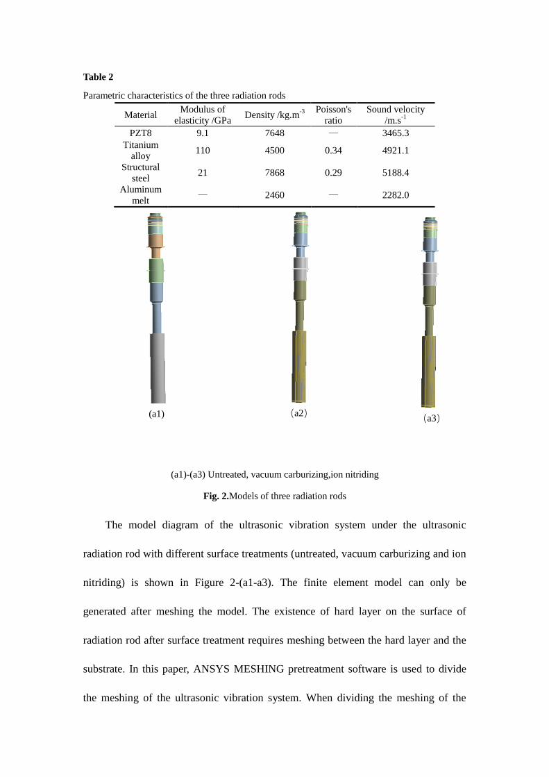
Table 2
Parametric characteristics of the three radiation rods
Material Modulus of
elasticity /GPa Density /kg.m
-3
Poisson's
ratio
Sound velocity
/m.s-1
PZT8 9.1 7648 — 3465.3
Titanium
alloy 110 4500 0.34 4921.1
Structural
steel 21 7868 0.29 5188.4
Aluminum
melt — 2460 — 2282.0
(a1)-(a3) Untreated, vacuum carburizing,ion nitriding
Fig. 2.Models of three radiation rods
The model diagram of the ultrasonic vibration system under the ultrasonic
radiation rod with different surface treatments (untreated, vacuum carburizing and ion
nitriding) is shown in Figure 2-(a1-a3). The finite element model can only be
generated after meshing the model. The existence of hard layer on the surface of
radiation rod after surface treatment requires meshing between the hard layer and the
substrate. In this paper, ANSYS MESHING pretreatment software is used to divide
the meshing of the ultrasonic vibration system. When dividing the meshing of the
(a1) (a2) (a3)

radiation rod without surface treatment, the mesh size is not set to 1mm. After
calculation, it can be concluded that the number of mesh cells is 4101761 and the
number of nodes is 11563583. Since the hard layer is only in micron magnitude, on
the premise of not affecting the calculation accuracy, it is set as shell element for grid
division. The contact mode between the hard layer and the matrix is set as binding
contact, and the grid size is 0.1mm. After calculation, the number of grid elements is
5811865 and the number of nodes is 23463694.
(a) Grid division diagram of untreated radiation rod
(b) Grid division diagram of radiation rod after surface treatment
Fig. 3. Mesh division diagram of ultrasonic vibration system
(3) Model loading and solving
Modal analysis: the positive and negative poles of the piezoelectric slice should
be coupled with voltage degrees of freedom, and the frequency range of modal

extraction was set as 18~ 22kHz. The fixed support plane was selected as the plane of
the piezoelectric ceramic rear end cover.
Harmonic response analysis: the harmonic response analysis frequency range is
set as 20~20.6KHz based on the natural frequency obtained from the modal analysis,
and the bolt pretightening force shall be added to the front end cover of the
piezoelectric ceramics.
The vibration direction and polarization direction of the piezoelectric ceramic
plate are set as the Y axis, and then the excitation voltage with the amplitude of
U=390V is added on the surface of the piezoelectric ceramic plate, and the voltage at
the top free surface is U=0V. The pretightening bolt force generated by the
pretightening bolt at the upper end of the piezoelectric ceramic sheet affects the
dynamic characteristics of the ultrasonic vibration system, and the pretightening bolt
force is set as 83.4N[13-16].
2.2Simulation of sound pressure field in aluminum melt
(1) Establishment of finite element model of fluid region
The sound field propagates in the medium. According to bounded or unbounded,
the distribution of the sound field is divided into near field and far field. In the
simulation of ultrasonic sound field distribution, the unbounded area is generally
selected for the acoustic analysis of simulation. For laboratory analysis of ultrasonic
casting system, sound wave propagates in aluminum melt, and it is generally difficult
to determine the distribution of sound field due to the absorption and reflection
characteristics of sound wave on crucible wall. Therefore, this paper adopts unbound
region to simulate the sound field [17-20].

Figure 4-(a) and 4-(b) are respectively the schematic diagram of the ultrasonic
casting system used in the experiment of this research group and the meshing diagram
in simulation. The ultrasonic vibration system is selected the same as above, the size
of ultrasonic radiation rod ∅50×350mm, and the radiation rod with ion nitriding and
vacuum carburizing thickness of 55μm and 53μm respectively after surface treatment
is selected. In order to facilitate the observation and selection of 1/2 section of the
model, the diameter of the molten pool D=630mm. In the three cases, the vibration
position is at the center of the molten pool, perpendicular to the molten pool, with a
depth of 280mm. The resonant frequency of the ultrasonic radiation rod is 20KHz.
Due to the working principle and action principle of the ultrasonic vibration system,
three fields of piezoelectric, acoustic and structure are required to be coupled during
the simulation[15]. The material properties of the ultrasonic vibration system are still
consistent with the previous dynamic simulation analysis, and the parameters of the
required components are shown in Table 2.
Fig. 4. Schematic diagram and mesh division diagram of ultrasonic casting system
(2) Boundary conditions and model loading

Setting of sound field boundary: the side and bottom of the molten pool are set as
absorption surfaces, the surface where the aluminum melt contacts with the radiation
rod is a free interface, and the structure-fluid coupling boundary conditions are
applied[14]. The excitation voltage U=390V on the surface of the piezoelectric
ceramic plates is used as the positive electrode, and the voltage U=0V on the top free
surface is used as the negative electrode. The analysis type was selected as acoustic
pressure harmonic response analysis, and the frequency range was set as 20kHz ~
20.6kHz. The material properties of aluminum melt are shown in Table 2.
2.3 The simulation results
(1) Analysis of dynamic characteristics of ultrasonic radiation rod
The dynamic simulation results, modal analysis and harmonic response analysis
results of the three kinds of ultrasonic radiation rods are shown in Fig. 5 and Fig. 6.
Fig. 5.Modal analysis diagram of three kinds of ultrasonic radiation rods
F=20558Hz
Displacement
(mm)
F=20552Hz
Displacement
(mm)
F=20561Hz
Displacement
(mm)
(b1)
Ionic
nitrid
ing
radiat
ion
rod(b
1)
(b2) (b3)
(b1)-(b3) Untreated, vacuum carburizing, ion nitriding

Fig. 6.Harmonic response analysis diagram of three radiation rods
① Modal analysis
The natural frequencies of three kinds of ultrasonic radiation rods from 19 kHz
to 22 kHz were extracted. According to the modal simulation result 5- (b1-b3), the
natural frequencies of three kinds of ultrasonic vibration systems were respectively
20558Hz, 20561Hz and 20552Hz, and the ultrasonic radiation rods were mainly
longitudinal vibration. It can be seen that the radiation rod after surface treatment has
little effect on the natural frequency of the ultrasonic vibration rod system.
② Harmonic response analysis
The modal superposition of the three radiation rods is performed to obtain the
vibration displacement at the natural frequency. The simulation results of harmonic
response analysis are shown in Fig. 6- (c1-c3). It can be seen from Fig. 6 that the end
face amplitudes of the three radiation rods are the largest, and the end face amplitudes
are 17.13μm, 13.23μm and 10.25μm respectively. The longitudinal vibration
F=20600Hz
Displacement
(μm)
F=20600Hz
Displacement
(μm)
F=20600Hz
Displacement
(μm)
(c1) (c2) (c3)
(c1)-(c3) Untreated, vacuum carburizing, ion nitriding

displacement of the ultrasonic radiation rod shows a trend of cosine vibration with the
distance from the end of the radiation rod. After the surface treatment, the amplitude
of the end face of the ultrasonic radiation rod decreased by 3.9 μm and 6.88 μm,
respectively, and the amplitude of the end face of the radiation rod treated by nitriding
was the smallest.
(2) Distribution of sound pressure field in aluminum melt
The acoustic pressure harmonic response analysis results of ultrasonic radiation
rod aluminum melt ultrasonic casting system with different surface treatments
(untreated, vacuum carburizing and ion nitriding) are shown in Fig.7. Through
comparison, it can be found that the acoustic pressure distribution field of ultrasonic
radiation rod treated by vacuum carburizing in aluminum melt is similar to that of
untreated and ion nitriding. The sound pressure field is distributed symmetrically with
the radiation rod as the center. Due to the large ultrasonic vibration energy of the end
face of the ultrasonic radiation rod, the sound pressure amplitude near it is the largest.
With the increase of the distance from the end face of the ultrasonic radiation rod, the
sound pressure amplitude decreases rapidly, and there are alternating positive and
negative pressures. A small area of low amplitude sound pressure appears on the side
of the radiation rod. But the amplitude of sound pressure in the three kinds of
radiation rod aluminum melt is obviously different. The amplitude of sound pressure
at the end of radiation rod is 4.3MPa, 3.6MPa and 3.3MPa, respectively. As can be
seen from Fig. 8, the change trend of sound pressure in aluminum melt and the
comparison of sound pressure amplitude in three kinds of radiation rod aluminum

melt show that the sound pressure amplitude of ultrasonic radiation rod in aluminum
melt after surface treatment is significantly reduced, and the sound pressure amplitude
generated by nitroded ultrasonic radiation rod in aluminum melt is the least.
Fig. 7. 1/2 cross section of sound pressure simulation results of three radiation rods
Fig. 8. Distribution of sound pressure field on cylinder surface of three ultrasonic casting systems
3.Estimation and experiment of cavitation field generated by three
kinds of ultrasonic radiation rods under ultrasonic vibration

The effect of power ultrasound depends on the cavitation domain generated by
the cavitation effect, and the distribution of the cavitation domain changes with the
change of the sound pressure field[21-22]. Due to the high temperature and closed
invisibility in the process of ultrasound-assisted casting, it is impossible to observe
directly. In order to more intuitively observe the distribution of ultrasonic sound
pressure field in the medium and compare it with the simulation results of the model.
Therefore, in this chapter, ultrasonic radiation rods with different surface treatments
were used to conduct aluminum foil cavitation erosion water experiment, and the
distribution of cavitation domain in water was observed based on the results of
aluminum foil cavitation erosion, so as to speculate the influence of the change of
sound pressure amplitude of the three radiation rods in aluminum melt on the
formation of ultrasonic radiation rod vibration on cavitation region.
3.1 Experimental equipment and scheme
The experiment uses water as liquid medium and pure aluminum foil as
corrosive material. The experimental equipment mainly includes: ultrasonic vibration
system (ultrasonic transducer, amplitude transformer, radiation rod) radiation rod
including untreated and carburizing, nitriding treatment of radiation rod. The radiation
rod is made of titanium alloy (Φ50× 380mm), and the ultrasonic power supply (18-
22kHz) can track the resonant frequency in real time and adjust the voltage. Auxiliary
equipment includes: beaker, adjustable support frame, hardboard, scotch tape, HD
camera.
Put an appropriate amount of water into the beaker and place it on the workbench.

Cut out the hard plate so that it can be put into the beaker. Cut out the concave hard
plate according to the insertion depth of the radiation rod so that the radiation rod can
be just inserted. The aluminum foil is also cut in the same way and fixed on both sides
of the board with transparent tape. The ultrasonic radiation rod was inserted into the
water, and the support frame was adjusted so that the depth of the submerged liquid
surface was 280mm. The ultrasonic power supply was connected to the ultrasonic
vibration system, and the frequency of the power supply was adjusted to 20kHz, the
voltage was 380V, the power was 600W, and the ultrasonic vibration time was 20s.
Turn off the ultrasonic power, take the aluminum foil out of the water and dry it to
observe the distribution of the corrosion holes over the filter. According to the above
process, the untreated, carburized and nitriding radiation rods were used for
experiments respectively. The schematic diagram and physical diagram of the
experimental device are shown in Fig. 9.
Fig.9.Schematic diagram and physical diagram of the experimental device for aluminum foil
cavitation erosion in water

3.2 Aluminum foil cavitation corrosion test results
Fig.10 is the experimental diagram of aluminum foil cavitation erosion in water
of three kinds of ultrasonic radiation rods. From the macro morphology of aluminum
foil cavitation corrosion, it can be observed that the surface of aluminum foil has
different degrees of corrosion, and cavitation exists in a specific area.
Fig.10 (a) shows the macroscopic distribution of aluminum foil corrosion when
untreated radiation rod is used. It can be seen that cavitation corrosion is mainly
concentrated in the range of about 40mm axial and 20mm radial under the end face of
radiation rod. Fig.(a1) is a local enlarged view of the cavitation area. It can be seen
that the depth and size of the pits are relatively uniform with the increase of the axial
distance.
Fig.10 (b) shows the macroscopic distribution of aluminum foil corrosion in
water when the radiation rod treated by carburizing is used. It can be seen that the
cavitation erosion area is mainly distributed in the range of about 35mm axial and
25mm radial under the end face of the radiation rod, and the cavitation holes in this
area are the most densely distributed. As can be seen from the local enlarged figure
(b1), the pitting holes are dispersed and the pitting depth and size are not uniform.
Fig.10 (c) shows the macroscopic distribution of aluminum foil corrosion when
nitriding radiation rod is used. It can be seen that the cavitation erosion area is mainly
concentrated in the range of about 30mm axial and 15mm radial of the end face of the
radiation rod. Through comparison, it can be found that the surface treated ultrasonic
radiation rod aluminum foil cavitation erosion area is obviously reduced, and the

number of pitting holes is small, the depth of pitting holes is shallow. Among the two
surface treatments, the cavitation erosion area and the degree of cavitation erosion are
the least in the aluminum foil under the radiator rod after ion nitriding.
Fig. 10.Macro morphology of aluminum foil cavitation etching in water experiment with three
kinds of ultrasonic radiation rods
4.Comparison and analysis of results
(1) Analysis of simulation results
According to the results of modal analysis and harmonious response analysis, the
amplitude of the end face of the ultrasonic radiation rod decreases by 33% and 46%
respectively after the surface treatment, which will lead to the decrease of the

ultrasonic power transferred to the aluminum melt. According to the simulation results
of sound pressure field in aluminum melt, the sound pressure amplitude of ultrasonic
radiation rod in aluminum melt after surface treatment is obviously lower, which
indicates that the ability of ultrasonic radiation rod to transfer ultrasonic power is
weakened after surface treatment, and the sound pressure value in aluminum melt is
reduced. This is consistent with the changing trend of the vibration amplitude of the
ultrasonic radiation rod. The surface treatment increases the surface elastic modulus
of the radiation rod, increases the vibration damping of the radiation rod, and suppress
the vibration of the ultrasonic radiation rod, which leads to the decrease of the
ultrasonic energy transmitted to the aluminum melt, and then affects the sound
pressure value in the aluminum melt. Moreover, the greater the elastic modulus is, the
more obvious the vibration suppression effect is. Therefore, the amplitude of sound
pressure generated at the end of the nitroded ultrasonic radiation rod is reduced by
about 23% compared with that of the untreated ultrasonic radiation rod, and the
vibration suppression effect of the radiation rod is the most obvious, making the
amplitude of sound pressure generated in the aluminum melt the least.
(2) Analysis of experimental results
The three kinds of ultrasonic radiation rod aluminum foil cavitation erosion
experiments respectively, can be found using the lever surface treatment of radiation
experiments the cavitation erosion area of the aluminum foil is lower than with
untreated radiation bar of aluminum foil cavitation erosion area, axial cavitation
erosion area reduced about 12.5% respectively, 25%, using ion nitriding treatment of

radiation rod, minimum cavitation erosion experiment of aluminum foil area. When
the sound pressure value generated by the ultrasonic vibration system in the aluminum
melt is greater than or equal to 1.1MPa, the collapse of cavitation bubbles in the
negative pressure state will lead to the occurrence of cavitation phenomenon in the
aluminum melt [23-24]. The decrease of sound pressure value will lead to the
decrease of the number of cavitation bubbles and the impact force of micro-jet
generated by the collapse of cavitation bubbles, and the damage degree to the
aluminum foil surface will be weakened. The results show that the acoustic pressure
generated by the surface treated ultrasonic radiation rod in the aqueous solution is
small, which affects the cavitation domain and the depth of the pitting hole.
(3) Comparison of Results
Comparison of sound pressure simulation results and aluminum foil cavitation
corrosion experiment is shown in Fig. 11. Approved by contrast can be found that the
surface treatment of radiation aluminum foil cavitation erosion area reduced obviously,
the axial cavitation erosion area reduced about 12.5%, respectively, 25%. The size of
cavitation erosion area reflects the size of sound pressure amplitude, that is, the results
of aluminum foil cavitation erosion experiment in water are similar to those of sound
pressure amplitude simulation, and cavitation holes are gradually sparse with the
increase of axial distance, indicating that the sound pressure amplitude is gradually
decreasing, which is the same as the distribution rule of sound pressure amplitude
obtained by sound pressure simulation. The sound pressure of surface treated
ultrasonic radiation rod in aqueous solution is smaller than that of untreated ultrasonic
radiation rod, and the sound pressure of ion nitriding radiation rod is the least. The

rationality of simulation results of sound pressure field is verified by experiments.
Fig. 11.Comparison between sound pressure simulation and aluminum foil cavitation etching
morphology
5.Conclusion
(1) Two kinds of surface treatment can reduce the amplitude of u ultrasonic
radiation rod by 4.9μm and 6.9μm, respectively. The acoustic pressure amplitude of
radiation rod in aluminum melt decreases by 0.7 MPa and 1 MPa, respectively. The
acoustic pressure amplitude of radiation rod treated by ion nitriding in aluminum melt
is the lowest.
(2) After surface treatment, the elastic modulus and hardness of the radiation rod
surface increase, the vibration response of the radiation rod is weakened, and the

amplitude of the radiation rod is reduced. The larger the surface elastic modulus of the
radiating rod is, the more obvious the inhibition effect on the vibration of the
ultrasonic radiating rod is.
References
[1] Ruiqing, Li, Zhilin,et al. Grain Refinement of a Large-Scale Al Alloy Casting by
Introducing the Multiple Ultrasonic Generators During Solidification[J].
Metallurgical and Materials Transactions A, 2016.
[2] Li Junwen, Tao Yezheng, Fu Ying, et al. Effect of ultrasonic power on porosity
and microstructure refinement in ingot [J]. Casting, 2007, 56 (002): 152-154157.
[3] Jiang ripeng, Li Xiaoqian. Study on influence law and action mechanism of
ultrasonic field on solidification process of high strength aluminum alloy [J].
Journal of mechanical engineering, 2016.
[4] Peng Botao, Li Xiaoqian, Zhang Lihua, et al. Study on Corrosion Behavior of
titanium alloy ultrasonic radiation rod in high temperature aluminum melt [J].
Hot working process, 2017, 046 (006): 119-122.
[5] Li Yongjian. Study on the action mechanism of surface morphology during
cavitation erosion [D]. Tsinghua University, 2009.
[6] Dong Fang, LI Xiao-qian, ZHANG Min. Cavitation experiment and mechanism
research of ultrasonic radiation rod in aluminum melt [J]. Journal of Huazhong
University of Science and Technology (Natural Science), 2015(2):85-88.
[7] Liu Zhe, Zhang Lihua, Peng Botao, et al. Effect of surface treatment on
corrosion resistance of ultrasonic radiation rod in aluminum melt [J]. Hot

working process, 2018.
[8] Tang C H, Cheng F T, Man H C. Effect of laser surface melting on the corrosion
and cavitation erosion behaviors of a manganese–nickel–aluminium bronze[J].
Materials Science & Engineering A, 2004, 373(1–2):195-203.
[9] A, Joon Hin Lee et al. "Numerical simulation on ultrasonic cavitation due to
superposition of acoustic waves." Materials ence for Energy Technologies
3(2020):593-600.
[10]Liao Huali, Liu Renxian. Study on vibration energy transmission performance of
power ultrasonic horn [J]. Mechanical design and manufacturing, 1999 (05): 71-
72.
[11]Geng Huanhuan. Theoretical research on testing Young's modulus of elasticity
and Poisson's ratio of thin films [D]. Chongqing University, 2011
[12]Tian Y , Liu Z , Li X ,et al. The cavitation erosion of ultrasonic sonotrode during
large-scale metallic casting: Experiment and simulation.[J]. Ultrasonics
Sonochemistry, 2018:S1350417717306375.
[13]Yasui K , Kozuka T , Tuziuti T ,et al. FEM calculation of an acoustic field in a
sonochemical reactor[J]. Ultrasonics Sonochemistry, 2007, 14(5):605-614.
[14]Jiang ripeng, Li Xiaoqian, Zhang Lihua, Hu Shicheng, Liu Rongguang. Effects
of vibration power and temperature on solidification structure of industrial pure
aluminum [J]. Journal of Beijing University of science and technology, 2008 (11):
1260-1265.
[15]Zhang min. effect of longitudinal and transverse vibration of ultrasonic radiation

rod on cavitation and fine grain region of aluminum melt [D]. Changsha: Central
South University, 2014.
[16]Du Gonghuan, Zhu Zhemin. Fundamentals of Acoustics - 3rd Edition [M].
Nanjing University Press, 2012.
[17]Jiang ripeng, Li Xiaoqian, Li Kaiye, et al. Effect and mechanism of ultrasound
on solidification heat transfer and microstructure formation of aluminum alloy
[J]. Journal of Central South University (NATURAL SCIENCE EDITION), 2012
(10): 3807-3813.
[18]Xie Enhua, Li Xiaoqian. Acoustic flow phenomenon in ultrasonic melt treatment
[J] Journal of Beijing University of science and technology, 2009, 31 (11): 59-62.
[19]Zhao Zhongxing. Homogenization effect of ultrasonic on alloy crystallization
process [J]. Hot working technology, 1999 (05): 10-11.
[20]Li Chao, Ying Chongfu, Bai Lixin, et al. Noise characteristics of hydrodynamic
cavitation and measurement of cavitation intensity [J]. Chinese Science: Physics,
mechanics and astronomy, 2012 (10): 987-995.
[21]Wang Y C , Yao M C . Realization of cavitation fields based on the acoustic
resonance modes in an immersion-type sonochemical reactor[J]. Ultrasonics
Sonochemistry, 2013, 20(1):565-570.
[22]Georgy I. Eskin. Effect of ultrasonic (cavitation) treatment of the melt on the
microstructure evolution during solidification of aluminum alloy ingots[J].
Ztschrift FurMetallkunde,2013,93(6):502-507.
[23]Shi Yeting. Study on cavitation resistance of pure titanium and TC4 titanium

alloy [D]. Tianjin University, 2012.
[24]Shen Pengfei. Test and analysis of vibration characteristics of integral blade disk
hard coating composite structure [D]. 2019.


