NREL is a national laboratory of the U.S. Department of Energy, Office of Energy Efficiency and Renewable Energy, operated by the Alliance for Sustainable Energy, LLC.
Electric Motor Thermal Management
Kevin Bennion National Renewable Energy Laboratory May 15, 2013
Project ID: APE030
This presentation does not contain any proprietary, confidential, or otherwise restricted information.
2
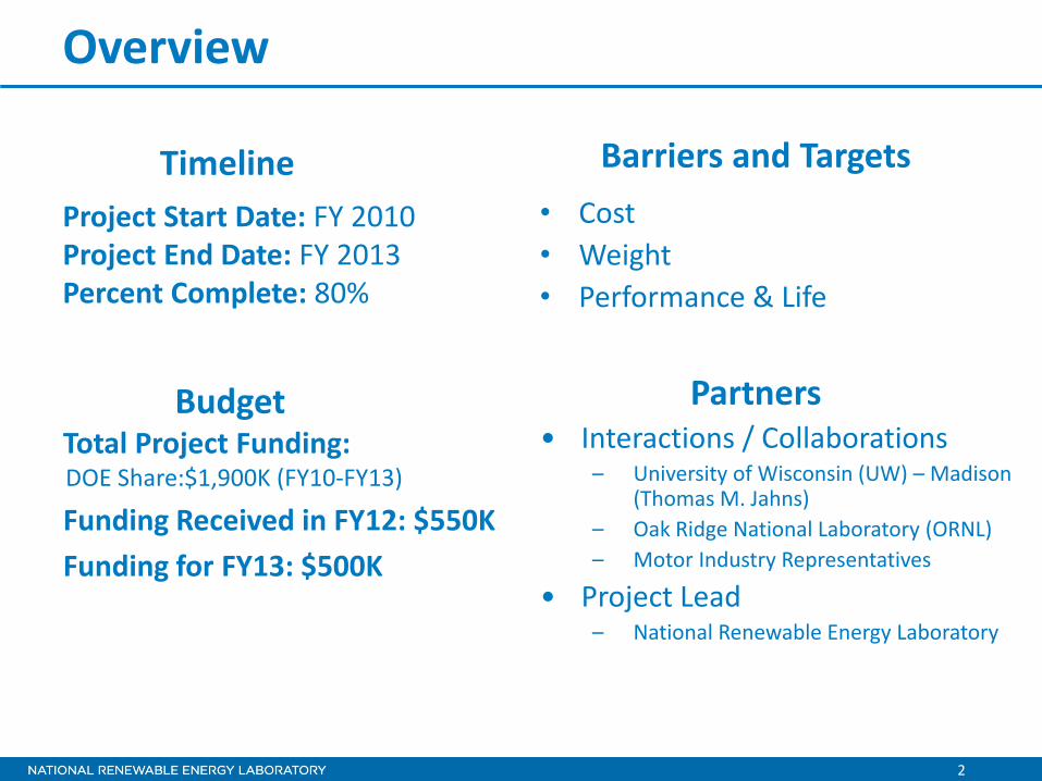
Overview
Project Start Date: FY 2010 Project End Date: FY 2013 Percent Complete: 80%
• Cost • Weight • Performance & Life
Total Project Funding: DOE Share:$1,900K (FY10-FY13)
Funding Received in FY12: $550K Funding for FY13: $500K
Timeline
Budget
Barriers and Targets
• Interactions / Collaborations – University of Wisconsin (UW) – Madison
(Thomas M. Jahns) – Oak Ridge National Laboratory (ORNL) – Motor Industry Representatives
• Project Lead – National Renewable Energy Laboratory
Partners

3
Relevance/Objectives
The transition to more electrically dominant propulsion systems leads to higher-power duty cycles for electric drive systems.
Continuous Operating Limit
Torq
ue
Speed
Thermally Limited Area of Operation
Transient Operating Limit
Thermal management is needed to reduce size and improve performance of electric motors. • Meet/improve power capability within
cost/efficiency constraints • Reduce rare earth material costs (dysprosium)
Targets Efficiency (%)
Cost ($/kW)
Weight (kW/kg)
Volume (kW/L)

4
Relevance/Objectives
The transition to more electrically dominant propulsion systems leads to higher-power duty cycles for electric drive systems.
Continuous Operating Limit
Torq
ue
Speed
Thermally Limited Area of Operation
Transient Operating Limit
Objectives • Quantify opportunities for improving cooling technologies for electric motors • Link thermal improvements to their impact on Advanced Power Electronics and
Electric Motors (APEEM) targets • Increase information related to motor thermal management in open literature
Addresses Targets • Translates cooling performance improvements into impacts on program targets • Prioritizes motor thermal management efforts based on areas of most impact

5
Milestones
Date Description January 2012 Go/No-Go
• Completed selected motor lamination material thermal property tests • Decided to not expand material tests at this time
July 2012 Go/No-Go • Thermal sensitivity analysis showed significant impact common to multiple
motor configurations leading to future project proposals for specific convective cooling enhancements and passive stack thermal improvements
September 2012 Milestone report • Lamination material thermal properties and motor thermal sensitivity
analysis
December 2012 Milestone (internal) • Completed transmission oil test bench for oil cooling experiments
September 2013 Milestone report • Final project summary report on lamination material thermal properties,
motor thermal sensitivity analysis, and oil heat transfer experimental data • Summarize collaborative motor cooling efforts with Oak Ridge National
Laboratory (ORNL)

6
Approach/Strategy
FY13 Focus
Credit: Kevin Bennion, NREL
Interior Permanent Magnet (IPM) Model Cross Section Transmission Oil Heat Transfer Experimental Setup

7
Approach/Strategy Cooling Technology Selection • Characterize heat transfer
coefficients of oil impingement cooling
• Investigate wire insulation reliability o Oil cooling impingement o High-potential breakdown
voltage tests
Credit: Kevin Bennion, NREL
Oil Impingement Test Chamber IPM Motor Model
IPM Motor Cooling Schematic Motor Axis

8
Approach/Strategy
IPM Motor Model Cross Section
Passive Thermal Design • Thermal interfaces between contacting
components provide significant resistance to heat flow.
• Interfaces are often difficult to characterize experimentally.
• Manufacturing variability increases the uncertainty of the interface thermal resistance.
9
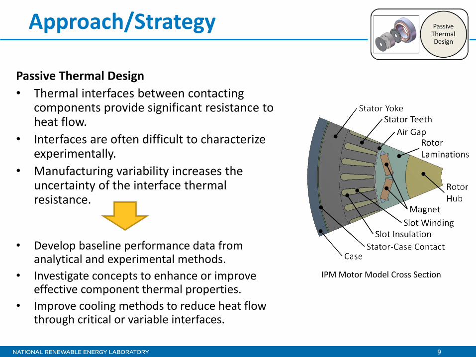
Approach/Strategy
• Develop baseline performance data from analytical and experimental methods.
• Investigate concepts to enhance or improve effective component thermal properties.
• Improve cooling methods to reduce heat flow through critical or variable interfaces.
Passive Thermal Design • Thermal interfaces between contacting
components provide significant resistance to heat flow.
• Interfaces are often difficult to characterize experimentally.
• Manufacturing variability increases the uncertainty of the interface thermal resistance.
IPM Motor Model Cross Section
10
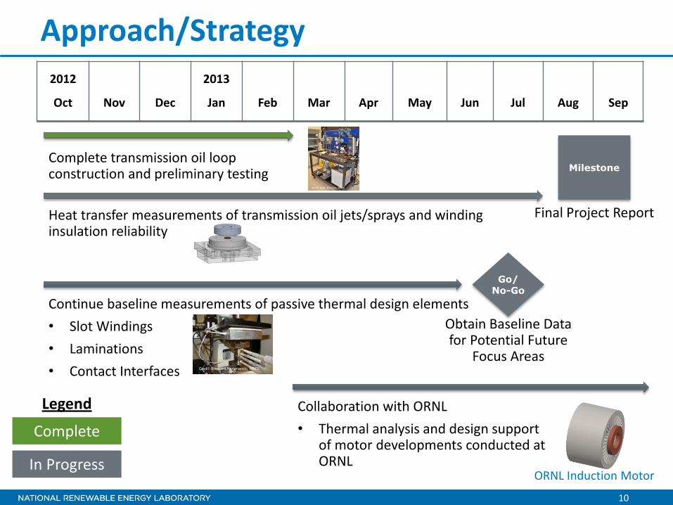
Approach/Strategy 2012
Oct
Nov
Dec
2013
Jan
Feb
Mar
Apr
May
Jun
Jul
Aug
Sep
Complete transmission oil loop construction and preliminary testing
Heat transfer measurements of transmission oil jets/sprays and winding insulation reliability
Go/ No-Go
In Progress
Legend
Complete
Obtain Baseline Data for Potential Future
Focus Areas
Collaboration with ORNL • Thermal analysis and design support
of motor developments conducted at ORNL
Milestone
Final Project Report
Continue baseline measurements of passive thermal design elements • Slot Windings • Laminations • Contact Interfaces
ORNL Induction Motor
Credit: Sreekant Narumanchi, NREL

11
Technical Accomplishments and Progress Completed phase one of partnership with the University of Wisconsin – Madison
• Review of thermal analysis and cooling techniques for traction drive motors • Developed a computationally efficient technique for estimating the loss
components in IPM motors as a function of the motor’s operating point • Developed a 3D finite element analysis (FEA) thermal model for a concentrated
winding stator motor configuration • Developed a thermal equivalent circuit (TEC) model for an IPM concentrated
winding motor
Preliminary thermal FEA showing temperature drop across slot liner for case cooled machine and thermal
gradients in winding Comparison of TEC model with FEA
temperature predictions
Concentrated winding motor
Slot Liner Credit: Thomas M. Jahns, Seth McElhinney (UW–Madison)
Winding

12
Technical Accomplishments and Progress Initiated phase two of partnership with the University of Wisconsin – Madison
• Model experimental validation and improvement • Investigating improved heat spreading methods
Litz Type 1 Twisted Wire Bundles
All Images - Credit: Thomas M. Jahns, Seth McElhinney (UW–Madison)
Untwisted Wire Bundles
170°C Maximum Temperature 139°C Maximum Temperature (Same Scale)
Preliminary analysis of twisted wire bundles show a hot spot temperature reduction of 30°C at rated torque and power

13
Technical Accomplishments and Progress
Cross Slot Thermal Conductivity
• Improvements to the slot filler material have little impact without improvements to the wire insulation thermal conductivity.
- 20 gauge Slot Winding Thermal Conductivity
0.155 W/m-K 0.11 W/m-K
78% Fill Factor with 20 Gauge Round Wire (Maximum Fill Factor)

14
Technical Accomplishments and Progress
Cross Slot Thermal Conductivity
• Improvements to the slot filler material and wire insulation are needed for reduced fill factors.
Slot Winding Thermal Conductivity
0.155 W/m-K 0.11 W/m-K
- 20 gauge 70% Fill Factor with 20 Gauge Round Wire

15
Technical Accomplishments and Progress
Cross Slot Thermal Conductivity
• Rectangular wire shows lower thermal conductivity at the same fill factor because of the lower conductivity filler material.
• Benefit of rectangular wire is seen if the thickness of the filler material boundaries are reduced.
20 gauge
Slot Winding Wire Shape
5.5 mm

16
Technical Accomplishments and Progress Oil Loop Experimental Setup • Mercon LV Transmission Fluid • Initial heat transfer tests focused on jet
impingement on target surface • Future work
• Alternative heat transfer coefficient measurement techniques
• Expand number of jets, target size, and target surface
• Wire insulation impacts
Test Chamber Credit: Kevin Bennion, NREL
Jet Orifice
Jet Target Surface
Resistive Heater Thermochromic Liquid
Crystal Thermocouple Surface Temperature Estimate
Alternative Convection Coefficient Measurement Methods

17
Technical Accomplishments and Progress
Credit: Gilbert Moreno, NREL
Credit: Gilbert Moreno, NREL
Area averaged heat transfer coefficient at 50°C fluid temperature

18
Collaboration and Coordination • University
– University of Wisconsin – Madison o Support with electric motor expertise
• Industry
– Motor industry suppliers, end users, and researchers o Input on research and test plans
• Other Government Laboratories
– Oak Ridge National Laboratory o Support from benchmarking activities o Ensure thermal design space is appropriate and modeling assumptions are
consistent with other aspects of APEEM research o Collaboration on motor designs to reduce or eliminate rare-earth materials
– Other Vehicle Technology Office (VTO) areas o Collaborate with VTO cross-cut effort for combined cooling loops

19
Future Work
Package Mechanical
Design
Cooling Technology Selection
Thermal Design Targets
Package Mechanical Design • Thermal tests of interfaces and materials
Cooling Technology Selection • Characterization of oil-cooling heat transfer coefficients • Oil cooling reliability tests (winding insulation)
Motor Thermal Design Targets • Collaboration with ORNL • Thermal analysis and design support of motor
developments conducted at ORNL
Credit: Sreekant Narumanchi, NREL
Credit: Gilbert Moreno, NREL
ORNL Induction Motor

20
Summary Relevance • Impacts the transition to more electrically dominant propulsion systems with higher continuous power
requirements • Enables improved performance of non-rare earth motors and supports lower cost through reduction
of rare earth materials used to meet temperature requirements (dysprosium)
Approach/Strategy • Engage in collaborations with motor design experts from industry, university, and national labs • Perform in-house thermal characterization of materials, interface thermal properties, and cooling
techniques • Collaborating with ORNL to provide motor thermal analysis support on related motor research at
ORNL
Technical Accomplishments • Completed thermal sensitivity analysis for a range of motor configurations and over a range of
operating conditions in collaboration with the University of Wisconsin – Madison • Evaluated impact of winding material improvements leading to future experimental test plans • Initiated heat transfer characterization tests involving transmission oil
Collaborations • University of Wisconsin – Madison • Oak Ridge National Laboratory • Motor industry representatives: manufacturers, researchers, and end users (light duty and heavy duty)

For more information, contact:
Principal Investigator Kevin Bennion [email protected] Phone: (303)-275-4447
APEEM Task Leader:
Sreekant Narumanchi [email protected] Phone: (303)-275-4062
Acknowledgments:
Susan Rogers and Steven Boyd, U.S. Department of Energy Andy Wereszczak, John Miller, Tim Burress, Randy Wiles, and Curt Ayers, Oak Ridge National Laboratory Team Members:
Justin Cousineau Douglas DeVoto Mark Mihalic Gilbert Moreno Thomas M. Jahns (UW–Madison) Seth McElhinney (UW–Madison)


