Download - Electrical Fittings Unistrut Construction
8/10/2019 Electrical Fittings Unistrut Construction
http://slidepdf.com/reader/full/electrical-fittings-unistrut-construction 1/22
161
®
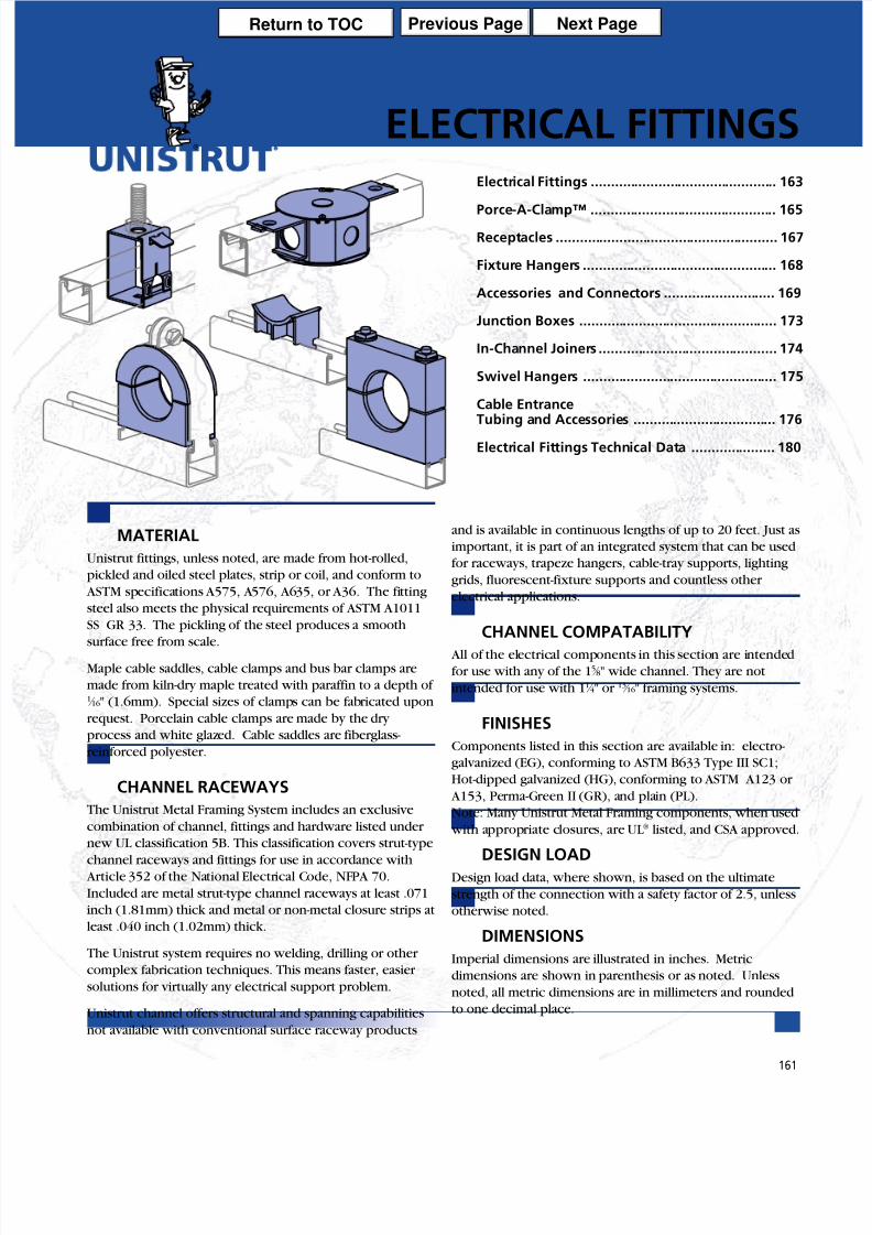
MATERIAL
Unistrut fittings, unless noted, are made from hot-rolled,
pickled and oiled steel plates, strip or coil, and conform to
ASTM specifications A575, A576, A635, or A36. The fitting
steel also meets the physical requirements of ASTM A1011
SS GR 33. The pickling of the steel produces a smooth
surface free from scale.
Maple cable saddles, cable clamps and bus bar clamps are
made from kiln-dry maple treated with paraffin to a depth of 1 ⁄ 16" (1.6mm). Special sizes of clamps can be fabricated upon
request. Porcelain cable clamps are made by the dry
process and white glazed. Cable saddles are fiberglass-
reinforced polyester.
CHANNEL RACEWAYS
The Unistrut Metal Framing System includes an exclusive
combination of channel, fittings and hardware listed under
new UL classification 5B. This classification covers strut-type
channel raceways and fittings for use in accordance with
Article 352 of the National Electrical Code, NFPA 70.
Included are metal strut-type channel raceways at least .071
inch (1.81mm) thick and metal or non-metal closure strips at
least .040 inch (1.02mm) thick.
The Unistrut system requires no welding, drilling or other
complex fabrication techniques. This means faster, easier
solutions for virtually any electrical support problem.
Unistrut channel offers structural and spanning capabilities
not available with conventional surface raceway products
and is available in continuous lengths of up to 20 feet. Just as
important, it is part of an integrated system that can be used
for raceways, trapeze hangers, cable-tray supports, lighting
grids, fluorescent-fixture supports and countless other
electrical applications.
CHANNEL COMPATABILITY All of the electrical components in this section are intended
for use with any of the 15 ⁄ 8" wide channel. They are not
intended for use with 11 ⁄ 4" or 13 ⁄ 16" framing systems.
FINISHES
Components listed in this section are available in: electro-
galvanized (EG), conforming to ASTM B633 Type III SC1;
Hot-dipped galvanized (HG), conforming to ASTM A123 or
A153, Perma-Green II (GR), and plain (PL).
Note: Many Unistrut Metal Framing components, when used
with appropriate closures, are UL® listed, and CSA approved.
DESIGN LOADDesign load data, where shown, is based on the ultimate
strength of the connection with a safety factor of 2.5, unless
otherwise noted.
DIMENSIONS
Imperial dimensions are illustrated in inches. Metric
dimensions are shown in parenthesis or as noted. Unless
noted, all metric dimensions are in millimeters and rounded
to one decimal place.
ELECTRICAL FITTINGSElectrical Fittings ............................................... 163
Porce-A-Clamp™ ............................................... 165
Receptacles ........................................................ 167
Fixture Hangers ................................................. 168
Accessories and Connectors ............................ 169
Junction Boxes .................................................. 173
In-Channel Joiners ............................................. 174
Swivel Hangers ................................................. 175
Cable Entrance
Tubing and Accessories .................................... 176Electrical Fittings Technical Data ..................... 180
Previous Page Next PageReturn to TOC
8/10/2019 Electrical Fittings Unistrut Construction
http://slidepdf.com/reader/full/electrical-fittings-unistrut-construction 2/22
162
®
Electrical Fittings
y
y
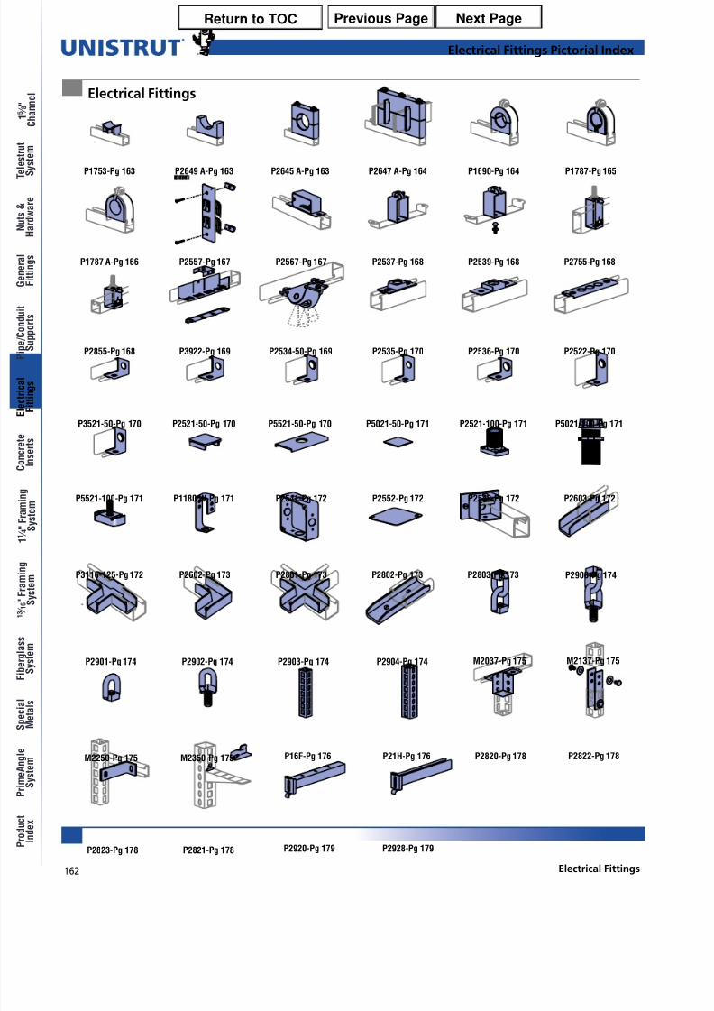
Electrical Fittings Pictorial Index
P1753-Pg 163 P2649 A-Pg 163 P2645 A-Pg 163 P2647 A-Pg 164 P1690-Pg 164 P1787-Pg 165
P2557-Pg 167P1787 A-Pg 166 P2567-Pg 167 P2537-Pg 168 P2539-Pg 168 P2755-Pg 168
P2855-Pg 168 P3922-Pg 169 P2534-50-Pg 169 P2535-Pg 170 P2536-Pg 170 P2522-Pg 170
P3521-50-Pg 170 P2521-50-Pg 170 P5521-50-Pg 170 P5021-50-Pg 171 P2521-100-Pg 171 P5021-100-Pg 171
P5521-100-Pg 171 P1180 W-Pg 171 P2541-Pg 172 P2540-Pg 172 P2603-Pg 172
P3116-125-Pg 172 P2602-Pg 173
P2552-Pg 172
P2801-Pg 173 P2802-Pg 173 P2803-Pg 173 P2900-Pg 174
P2901-Pg 174 M2137-Pg 175
M2250-Pg 175 M2350-Pg 175
P2902-Pg 174 P2903-Pg 174 P2904-Pg 174 M2037-Pg 175
Electrical Fittings
P16F-Pg 176 P21H-Pg 176 P2822-Pg 178
P2823-Pg 178 P2821-Pg 178
P2820-Pg 178
P2920-Pg 179 P2928-Pg 179
Previous Page Next PageReturn to TOC
8/10/2019 Electrical Fittings Unistrut Construction
http://slidepdf.com/reader/full/electrical-fittings-unistrut-construction 3/22
163Electrical Fittings
Electrical Fittings
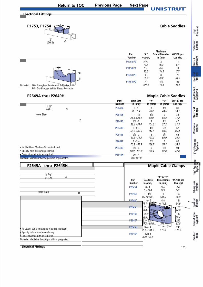
P2649A thru P2649H Maple Cable Saddles
P2645A thru P2645H Maple Cable Clamps
P1753, P1754 Cable Saddles
• 3 ⁄ 8" studs, square nuts and washers included.
• Specify hole size when ordering.
• Order channel nuts as required.
Material: Maple hardwood paraffin impregnated.
•3
⁄ 8" Flat Head Machine Screw included.• Specify hole size when ordering.
• Order channel nuts as required.
Material: Maple hardwood paraffin impregnated.
A(50.8)
2"
Material: FG - Fiberglass Reinforced Polyester,PO - Dry Process White Glazed Porcelain
A(41.3)1 5 ⁄ 8"
B
Hole Size
Hole Size
A1 5 ⁄ 8"
B
(41.3)
MaximumPart “A” Cable Diameter Wt/100 pcs
Number In (mm) In (mm) Lbs (kg)
P1753 FG 213 ⁄ 16 3 1271.4 76.2 5.4
P1754 FG 33 ⁄ 4 41 ⁄ 2 1795.3 114.3 7.7
P1753 PO 3 3 7576.2 76.2 34.0
P1754 PO 4 41 ⁄ 2 95101.6 114.3 43.1
Part Hole Size “A” “B” Wt/100 pcs Number In (mm) In (mm) In (mm) Lbs (kg)
P2649A 0 - 1 3 13 ⁄ 4 310 - 25.4 76.2 44.5 14.1
P2649B 1 - 11 ⁄ 2 31 ⁄ 2 2 3825.4 x 38.1 88.9 50.8 17.2
P2649C 11 ⁄ 2 - 2 4 21 ⁄ 4 4738.1 - 50.8 101.6 57.2 21.3
P2649D 2 - 21 ⁄ 2 41 ⁄ 2 21 ⁄ 2 5750.8 x 63.5 114.3 63.5 25.9
P2649E 21 ⁄ 2 - 3 5 23 ⁄ 4 6863.5 - 76.2 127.0 69.9 30.8
P2649F 3 - 31 ⁄ 2 51 ⁄ 2 3 8076.2 x 88.9 139.7 76.2 36.3
P2649G 31 ⁄ 2 - 4 6 31 ⁄ 4 9488.9 - 101.6 152.4 82.6 42.6
P2649H over 4over 101.6
“A” & “B”Part Hole Size Dimensions Wt/100 pcs
Number In (mm) In (mm) Lbs (kg)
P2645A 0 - 1 31 ⁄ 2 840 - 25.4 88.9 38.1
P2645B 1 - 11 ⁄ 2 4 102
25.4 x 38.1 101.6 46.3 P2645C 11 ⁄ 2 - 2 41 ⁄ 2 121
38.1 - 50.8 114.3 54.9
P2645D 2 - 21 ⁄ 2 51 ⁄ 2 16550.8 x 63.5 139.7 74.8
P2645E 21 ⁄ 2 - 3 6 18963.5 - 76.2 152.4 85.7
P2645F 3 - 31 ⁄ 2 61 ⁄ 2 21576.2 x 88.9 165.1 97.5
P2645G 31 ⁄ 2 - 4 7 24388.9 - 101.6 177.8 110.2
P2645H over 4over 101.6
Previous Page Next PageReturn to TOC

8/10/2019 Electrical Fittings Unistrut Construction
http://slidepdf.com/reader/full/electrical-fittings-unistrut-construction 4/22
164
®
Electrical Fittings
y
y
Material: Paraffin impregnated maple hardwood.
• 1 ⁄ 2" studs, square nuts and washers are included.
• Channel nuts must be ordered separately.
• Bus bar maple clamps also available in1 ⁄ 4" (6.4) x 2" (50.8) and 1 ⁄ 4" (6.4) x 6" (152.4).
• Use with steel clamp and Everdur hardware.
Order clamp separately.• Specify hole size when ordering.
(41.3)1 5 ⁄ 8"
A
4"(101.6)
1 ⁄ 4" (5.4) MapleSeparator
7 3 ⁄ 8"(187.3)
B
Material: Paraffin impregnated maple hardwood.
Hole Size
A
P1690 thru P1697 Maple Cable Clamps
P2647A thru P2647F 4" (101.6) Bus Bar Maple Clamps
Part “A” “B” No. Bus No. Bars Wt/100 pcsNumber In (mm) In (mm) Separators Per Leg Lbs (kg)
P2647A 81 ⁄ 2 9 ⁄ 32 0 1 421215.9 7.1 191.0
P2647B 91 ⁄ 2 13 ⁄ 16 2 2 465241.3 20.6 210.9
P2647C 101
⁄ 2 15
⁄ 16 4 3 509266.7 33.3 230.9
P2647D 111 ⁄ 2 113 ⁄ 16 6 4 553292.1 46.0 250.8
P2647E 121 ⁄ 2 23 ⁄ 8 8 5 597317.5 60.3 270.8
P2647F 131 ⁄ 2 27 ⁄ 8 10 6 631342.9 73.0 286.2
Order SteelPart Clamp Hole Size “A” Wt/100 pcs
Number Number In (mm) In (mm) Lbs (kg)
P1690 P1113 E 0 -5 ⁄ 8 11 ⁄ 2 240 - 15.9 38.1 10.9
P1691 P1115 E 1 ⁄ 2 - 1 21 ⁄ 8 4212.7- 25.4 54.0 19.1
P1692 P1117 E 3 ⁄ 4 - 11 ⁄ 2 25 ⁄ 8 5419.1 x 38.1 66.7 24.5
P1693 P1118 E 11 ⁄ 4 - 13 ⁄ 4 3 6531.8 x 44.5 76.2 29.5
P1694 P1119 E 11 ⁄ 2 - 21 ⁄ 4 35 ⁄ 8 8438.1 x 57.2 92.1 38.1
P1695 P1120 E 2 - 21 ⁄ 2 41 ⁄ 8 10750.8 x 63.5 104.8 48.5
P1696 P1121 E 21 ⁄ 4 - 3 45 ⁄ 8 12357.2 - 76.2 117.5 55.8
P1697 P1123 E 3 - 4 53 ⁄ 4 16376.2 - 101.6 146.1 73.9
Electrical Fittings
Previous Page Next PageReturn to TOC
8/10/2019 Electrical Fittings Unistrut Construction
http://slidepdf.com/reader/full/electrical-fittings-unistrut-construction 5/22
165Electrical Fittings
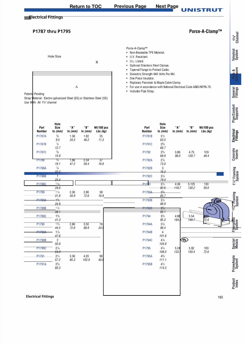
P1787 thru P1795 Porce-A-Clamp™
HolePart Size “A” “B” Wt/100 pcs
Number In (mm) In (mm) In (mm) Lbs (kg)
P1787A 3 ⁄ 8 1.36 1.82 259.5 34.5 46.2 11.3
P1787B 1 ⁄ 212.7
P1787C 5 ⁄ 815.9
P1788 3 ⁄ 4 1.86 2.34 3719.1 47.2 59.4 16.8
P1788A 7 ⁄ 822.2
P1788B 125.4
P1788C 11 ⁄ 828.6
P1789 11 ⁄ 4 2.36 2.86 5831.8 59.9 72.6 16.8
P1789A 13 ⁄ 834.9
P1789B 11 ⁄ 238.1
P1789C 15 ⁄ 841.3
P1790 13 ⁄ 4 2.86 3.50 7644.5 72.6 88.9 34.5
P1790A 17 ⁄ 8
47.6 P1790B 2
50.8
P1790C 21 ⁄ 854.0
P1791 21 ⁄ 4 3.36 4.05 9057.2 85.3 102.9 40.8
P1791A 23 ⁄ 860.3
Patents Pending
Strap Material: Electro-galvanized Steel (EG) or Stainless Steel (SS)
Use With: All 15 ⁄ 8" channel
Porce-A-Clamp™
• Non-Breakable TPE Material.
• U.V. Resistant.
• U.L. Listed.
• Optional Stainless Steel Clamps.
• Tapered Flange to Protect Cable.
• Dielectric Strength 640 Volts Per Mil.
• One Piece Insulator.
• Replaces Porcelain & Maple Cable Clamp.
• For use in accordance with National Electrical Code ANSI/NFPA 70.
• Includes Pipe Strap.
HolePart Size “A” “B” Wt/100 pcs
Number In (mm) In (mm) In (mm) Lbs (kg)
P1791B 21 ⁄ 263.5
P1791C 25 ⁄ 866.7
P1792 23 ⁄ 4 3.86 4.75 10969.9 98.0 120.7 49.4
P1792A 27 ⁄ 873.0
P1792B 376.2
P1792C 31 ⁄ 879.4
P1793 31 ⁄ 4 4.36 5.125 13082.6 110.7 130.2 59.0
P1793A 33 ⁄ 885.7
P1793B 31 ⁄ 288.9
P1793C 35 ⁄ 892.1
P1794 33 ⁄ 4 4.86 5.54 16095.3 184.2 140.7 72.6
P1794A 37 ⁄ 898.4
P1794B 4
101.6 P1794C 41 ⁄ 8
104.8
P1795 41 ⁄ 4 5.24 5.92 160108.0 133.1 150.4 72.6
P1795A 43 ⁄ 8111.1
P1795B 41 ⁄ 2114.3
Electrical Fittings
Hole Size
A
B
Previous Page Next PageReturn to TOC
8/10/2019 Electrical Fittings Unistrut Construction
http://slidepdf.com/reader/full/electrical-fittings-unistrut-construction 6/22
166
®
Electrical Fittings
y
y
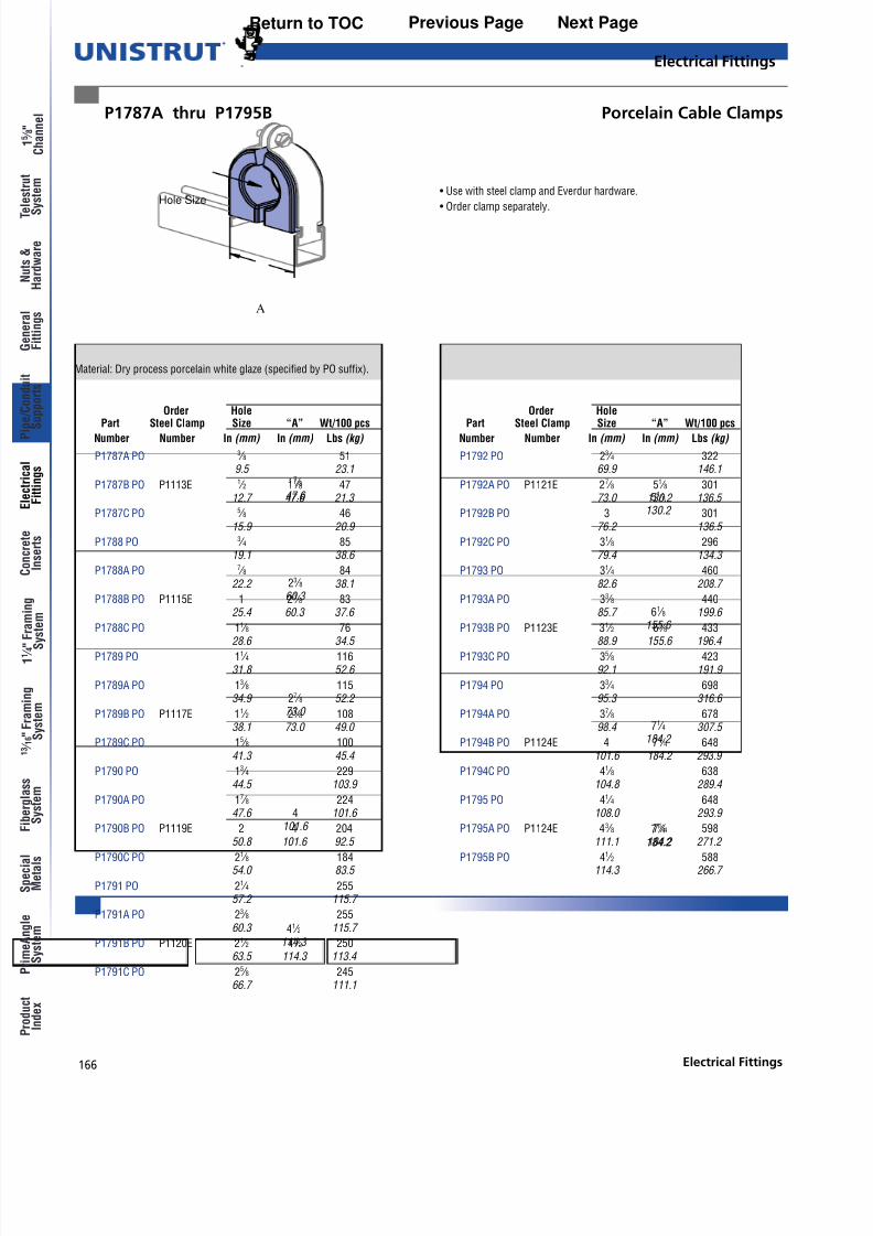
P1787A thru P1795B Porcelain Cable Clamps
Material: Dry process porcelain white glaze (specified by PO suffix).
• Use with steel clamp and Everdur hardware.
• Order clamp separately.
Hole Size
A
Order Hole
Part Steel Clamp Size “A” Wt/100 pcs Number Number In (mm) In (mm) Lbs (kg)
P1787A PO 3 ⁄ 8 519.5 23.1
P1787B PO P1113E 1 ⁄ 2 17 ⁄ 8 4712.7 47.6 21.3
P1787C PO 5 ⁄ 8 4615.9 20.9
P1788 PO 3 ⁄ 4 8519.1 38.6
P1788A PO 7 ⁄ 8 8422.2 38.1
P1788B PO P1115E 1 23 ⁄ 8 8325.4 60.3 37.6
P1788C PO 11 ⁄ 8 76
28.6 34.5
P1789 PO 11 ⁄ 4 11631.8 52.6
P1789A PO 13 ⁄ 8 11534.9 52.2
P1789B PO P1117E 11 ⁄ 2 27 ⁄ 8 10838.1 73.0 49.0
P1789C PO 15 ⁄ 8 10041.3 45.4
P1790 PO 13 ⁄ 4 22944.5 103.9
P1790A PO 17 ⁄ 8 22447.6 101.6
P1790B PO P1119E 2 4 20450.8 101.6 92.5
P1790C PO 21 ⁄ 8 18454.0 83.5
P1791 PO 21 ⁄ 4 25557.2 115.7
P1791A PO 23 ⁄ 8 25560.3 115.7
P1791B PO P1120E 21 ⁄ 2 41 ⁄ 2 25063.5 114.3 113.4
P1791C PO 25 ⁄ 8 24566.7 111.1
Order Hole
Part Steel Clamp Size “A” Wt/100 pcs Number Number In (mm) In (mm) Lbs (kg)
P1792 PO 23 ⁄ 4 32269.9 146.1
P1792A PO P1121E 27 ⁄ 8 51 ⁄ 8 30173.0 130.2 136.5
P1792B PO 3 30176.2 136.5
P1792C PO 31 ⁄ 8 29679.4 134.3
P1793 PO 31 ⁄ 4 46082.6 208.7
P1793A PO 33 ⁄ 8 44085.7 199.6
P1793B PO P1123E 31 ⁄ 2 61 ⁄ 8 433
88.9 155.6 196.4
P1793C PO 35 ⁄ 8 42392.1 191.9
P1794 PO 33 ⁄ 4 69895.3 316.6
P1794A PO 37 ⁄ 8 67898.4 307.5
P1794B PO P1124E 4 71 ⁄ 4 648101.6 184.2 293.9
P1794C PO 41 ⁄ 8 638104.8 289.4
P1795 PO 41 ⁄ 4 648108.0 293.9
P1795A PO P1124E 43 ⁄ 8 71 ⁄ 4 598111.1 184.2 271.2
P1795B PO 41 ⁄ 2 588114.3 266.7
Electrical Fittings
17 ⁄ 847.6
23 ⁄ 860.3
27 ⁄ 873.0
4101.6
41 ⁄ 2114.3
71 ⁄ 4184.2
71 ⁄ 4184.2
61 ⁄ 8155.6
51 ⁄ 8130.2
Previous Page Next PageReturn to TOC
8/10/2019 Electrical Fittings Unistrut Construction
http://slidepdf.com/reader/full/electrical-fittings-unistrut-construction 7/22
167Electrical Fittings
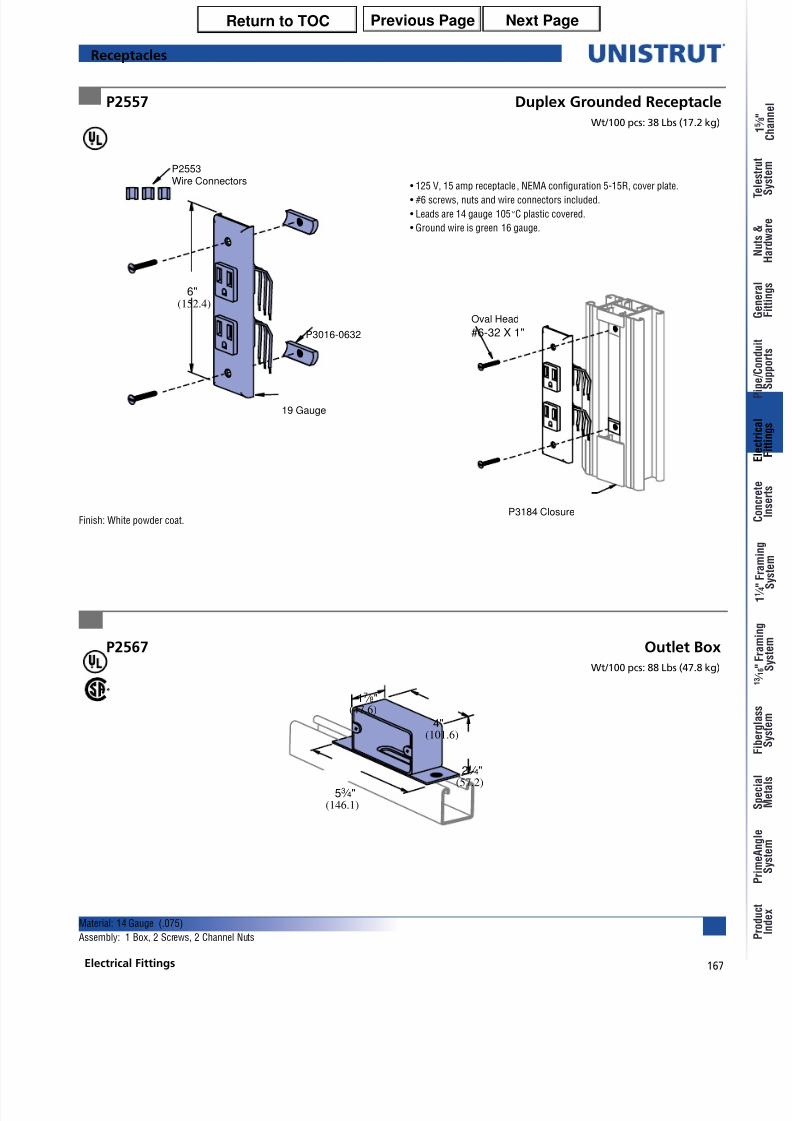
P2567 Outlet Box
P2557 Duplex Grounded Receptacle
Wt/100 pcs: 38 Lbs (17.2 kg)
• 125 V, 15 amp receptacle , NEMA configuration 5-15R, cover plate.
• #6 screws, nuts and wire connectors included.
• Leads are 14 gauge 105°C plastic covered.
• Ground wire is green 16 gauge.
6"(152.4)
P3016-0632
19 Gauge
P2553Wire Connectors
Finish: White powder coat.
Oval Head
#6-32 X 1"
P3184 Closure
Material: 14 Gauge (.075)
Assembly: 1 Box, 2 Screws, 2 Channel Nuts
(47.6)17 ⁄ 8"
(101.6)4"
(146.1)53 ⁄ 4"
(57.2)21 ⁄ 4"
Receptacles
Wt/100 pcs: 88 Lbs (47.8 kg)
Previous Page Next PageReturn to TOC

8/10/2019 Electrical Fittings Unistrut Construction
http://slidepdf.com/reader/full/electrical-fittings-unistrut-construction 8/22
168
®
Electrical Fittings
y
y
P2537, P5537Fluorescent Fixture Hangers
P2539, P3539, P5539Fluorescent Fixture Hangers
P2755, P2756, P2757 Raceway Hangers P2855, P2856, P2857 Raceway Hangers
• Hanger provides more than1 ⁄ 2" (12.7) space betweenchannel and fixtures.
Materials: 18 gauge (1.2).
• Hanger provides 1 ⁄ 8" (3.2)space between channeland fixtures.
Materials: 18 gauge (1.2).
Use with Channels:
P1001, P1101, P2001, P5000, & P5500.
Material: 14 gauge (1.9).
Use with Channels:
P1000, P1100, P3000, P3300
Material: 14 gauge (1.9).
1 ⁄ 4" X 1" RHMS andSq. Nut Included
A
9 ⁄ 32" (7.1) Dia. Hole
1 5 ⁄ 8"(41.3)
(108.0)4 1 ⁄ 4"
A
9 ⁄ 32" (7.1)
Sq. Hole
9 ⁄ 32" (7.1)
Sq. Hole
2 3 ⁄ 4"(69.9)
A
A
(41.3)1 5 ⁄ 8"
1 ⁄ 4" X 3 ⁄ 4"Carriage Boltand Sq. Nut Included
1 ⁄ 4" X 1" RHMS andSq. Nut Included
Design Load120 Lbs (54.4 kg)
Design Load120 Lbs (54.4 kg)
Design Load120 Lbs (54.4 kg)
Design Load120 Lbs (54.4 kg)
UsePart With “A” Wt/100 pcs
Number Channel In (mm) Lbs (kg)
P1000P2537 P1100 27 ⁄ 16 19
P3000 61.9 8.6
P5537 P5500 31 ⁄ 4 2282.6 10.0
UsePart With “A” Wt/100 pcs
Number Channel In (mm) Lbs (kg)
P1000P2539 P1100 13 ⁄ 4 17
44.5 7.7
P3539 P3000 11 ⁄ 2 1538.1 6.8
P5539 P5500 29 ⁄ 16 1865.1 8.2
Part “A” Wt/100 pcs
Number In (mm) Lbs (kg)
P2755 9 ⁄ 16 4414.3 20.0
P2756 7 ⁄ 8 4422.2 20.0
P2757 13 ⁄ 32 4410.3 20.0
Part “A” Wt/100 pcs
Number In (mm) Lbs (kg)
P2855 9 ⁄ 16 3214.3 14.5
P2856 7 ⁄ 8 3222.2 14.5
P2857 13 ⁄ 32 3210.3 14.5
Fluorescent Fixture Hangers
Previous Page Next PageReturn to TOC
8/10/2019 Electrical Fittings Unistrut Construction
http://slidepdf.com/reader/full/electrical-fittings-unistrut-construction 9/22
169Electrical Fittings
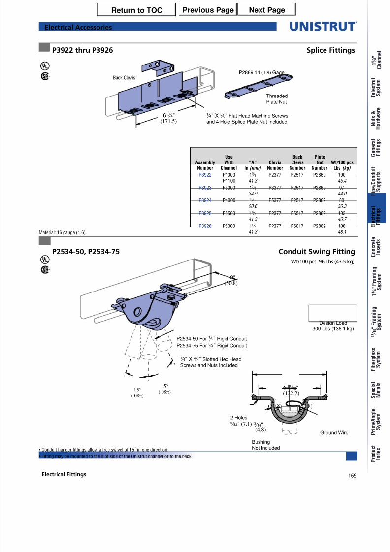
P2534-50, P2534-75 Conduit Swing Fitting
P3922 thru P3926 Splice Fittings
Wt/100 pcs: 96 Lbs (43.5 kg)
Material: 16 gauge (1.6).
• Conduit hanger fittings allow a free swivel of 15 ° in one direction.
• Fitting may be mounted to the slot side of the Unistrut channel or to the back.
15°(.08π)
2"
(50.8)
P2534-50 For 1 ⁄ 2" Rigid Conduit
P2534-75 For 3 ⁄ 4" Rigid Conduit
1 ⁄ 4" X 3 ⁄ 4" Slotted Hex HeadScrews and Nuts Included
15°(.08π)
Ground Wire
2 Holes9 ⁄ 32" (7.1)
2"(50.8)
2"(50.8)
4 13 ⁄ 16"(122.2)
(4.8)
3 ⁄ 16"
BushingNot Included
Design Load300 Lbs (136.1 kg)
Use Back PlateAssembly With “A” Clevis Clevis Nut Wt/100 pcsNumber Channel In (mm) Number Number Number Lbs (kg)
P3922 P1000 15 ⁄ 8 P2377 P2517 P2869 100P1100 41.3 45.4
P3923 P3000 1
3
⁄ 8 P3377 P2517 P2869 9734.9 44.0
P3924 P4000 13 ⁄ 16 P5377 P2517 P2869 8020.6 36.3
P3925 P5500 15 ⁄ 8 P2377 P5517 P2869 10341.3 46.7
P3926 P5000 15 ⁄ 8 P2377 P5017 P2869 10641.3 48.1
Electrical Accessories
6 3 ⁄ 4"(171.5)
1 ⁄ 4" X 5 ⁄ 8" Flat Head Machine Screwsand 4 Hole Splice Plate Nut Included
P2869 14 (1.9) Gage
ThreadedPlate Nut
Back Clevis
Previous Page Next PageReturn to TOC
8/10/2019 Electrical Fittings Unistrut Construction
http://slidepdf.com/reader/full/electrical-fittings-unistrut-construction 10/22
170
®
Electrical Fittings
y
y
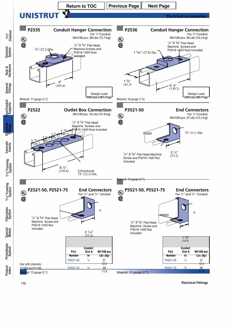
P2535 Conduit Hanger ConnectionFor 1 ⁄ 2"Conduit
Wt/100 pcs: 28 Lbs (12.7 kg)
P2536 Conduit Hanger ConnectionFor 3 ⁄ 4"Conduit
Wt/100 pcs: 36 Lbs (16.3 kg)
P2522 Outlet Box ConnectionWt/100 pcs: 35 Lbs (15.9 kg)
P3521-50 End ConnectorsFor 1 ⁄ 2"Conduit
Wt/100 pcs: 27 Lbs (12.2 kg)
P2521-50, P2521-75 End ConnectorsFor 1 ⁄ 2" and 3 ⁄ 4" Conduit
P5521-50, P5521-75 End ConnectorsFor 1 ⁄ 2" and 3 ⁄ 4" Conduit
2 1 ⁄ 16"(52.4)
A
1 ⁄ 4" X 5 ⁄ 8" Flat HeadMachine Screw and
P3016-1420 NutIncluded
1 15 ⁄ 16"(49.2)
1 ⁄ 4" X 5 ⁄ 8" Flat HeadMachine Screws andP3016-1420 Nuts Included
1 3 ⁄ 16"(30.2)1 3 ⁄ 16"
(30.2)1 15 ⁄ 16"(49.2)
6 1 ⁄ 4"(158.8) 3 Knockouts
7 ⁄ 8" (22.2) Dia.
Material: 12 gauge (2.7). Material: 16 gauge (1.5)
Material: 12 gauge (2.7).
Material: 12 gauge (2.7).
Use with channels:
P1000 and P1100.
Material: 12 gauge (2.7)
7 ⁄ 8" (22.2) Dia.
(101.6)
1 ⁄ 4" X 5 ⁄ 8" Flat HeadMachine Screws andP3016-1420 Nuts
Included
4"
1 3 ⁄ 32" (27.8) Dia.
(130.2)
1 5 ⁄ 8"(41.3)
1 ⁄ 4" X 5 ⁄ 8" Flat HeadMachine Screws andP3016-1420 Nuts Included
5 1 ⁄ 8"
7 ⁄ 8" (22.2) Dia.
2 1 ⁄ 4"(57.2)
1 ⁄ 4" X 5 ⁄ 8" Flat Head MachineScrew and P3016-1420 NutIncluded
P3000
1 3 ⁄ 8"(34.9)
AP5500
1 ⁄ 4" X 5 ⁄ 8" Flat Head
Machine Screw andP3016-1420 NutIncluded
Design Load400 Lbs (181.4 kg)
Design Load200 Lbs (90.7 kg)
ConduitPart Size A Wt/100 pcs
Number In Lbs (kg)
P2521-50 1 ⁄ 2 2712.2
P2521-75 3 ⁄ 4 2611.8
ConduitPart Size A Wt/100 pcs
Number In Lbs (kg)
P5521-50 1 ⁄ 2 2712.2
P5521-75 3 ⁄ 4 2611.8
Electrical Accessories
Previous Page Next PageReturn to TOC
8/10/2019 Electrical Fittings Unistrut Construction
http://slidepdf.com/reader/full/electrical-fittings-unistrut-construction 11/22
171Electrical Fittings
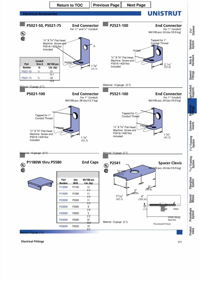
P5021-50, P5021-75 End ConnectorFor 1 ⁄ 2" and 3 ⁄ 4" Conduit
P2521-100 End ConnectorFor 1" Conduit
Wt/100 pcs: 24 Lbs (10.9 kg)
P5021-100 End ConnectorFor 1" Conduit
Wt/100 pcs: 28 Lbs (12.7 kg)
P5521-100 End ConnectorFor 1" Conduit
Wt/100 pcs: 24 Lbs (10.9 kg)
P1180W thru P5580 End Caps
Material: 12 gauge (2.7).Material: 12 gauge (2.7).
Material: 12 gauge (2.7). Material: 12 gauge (2.7).
(41.3)1 5 ⁄ 8"
A
P5000
1 ⁄ 4" X 5 ⁄ 8" Flat HeadMachine Screw andP3016-1420 NutIncluded
1 5 ⁄ 8"(41.3)
P5000
Tapped for 1"Conduit Thread
1 ⁄ 4" X 5 ⁄ 8" Flat HeadMachine Screw andP3016-1420 NutIncluded
Tapped for 1"Conduit Thread
(52.4)
P1000
1 ⁄ 4" X 5 ⁄ 8" Flat HeadMachine Screw andP3016-1420 NutIncluded
2 1 ⁄ 16"
1 5 ⁄ 8"(41.3)
P5500
Tapped for 1"Conduit Thread
1 ⁄ 4" X 5 ⁄ 8" Flat HeadMachine Screw andP3016-1420 NutIncluded
Material: 14 gauge (1.9)
Part Use Wt/100 pcs
Number With Lbs (kg)
P1180W P1100 125.4
P1280W P1000 115.0
P2280W P2000 115.0
P3280W P3000 83.6
P4280W P4000 52.3
P5280W P5000 2210.0
P5580W P5500 188.2
ConduitPart Size A Wt/100 pcs
Number In Lbs (kg)
P5021-50 1 ⁄ 2 3114.1
P5021-75 3 ⁄ 4 3013.6
Electrical Accessories
P2541 Spacer Clevis
Wt/100 pcs: 24 Lbs (10.9 kg)
Material: 12 gauge (2.7).
2"
(50.8)
(101.6)121 ⁄ 32"(42.1)
7 ⁄ 8" DIA.(22.2)
(50.8)
4"
2"
1 ⁄ 8"(3.2)
UNISTRUT Channel
Flourescent Fixture
P2541
P2540 Wiring
Stud Nut
Previous Page Next PageReturn to TOC

8/10/2019 Electrical Fittings Unistrut Construction
http://slidepdf.com/reader/full/electrical-fittings-unistrut-construction 12/22
172
®
Electrical Fittings
y
y
P2552 Polypropylene Wire Retainer P2540, P2540A Wiring Stud Nut
P2603 Fixture Wiring Nipple P3116-125 Fixture Stud Nut
Wt/100 pcs: 11 Lbs (5.0 kg)
Material: Sintered metal.
Retainer may be easily pushed intochannel to support wires untilclosure strip is installed.
Wt/100 pcs: .30 Lbs (.1 kg)
A
1 1 ⁄ 2"(38.1)
1 1 ⁄ 2"(38.1)
1 ⁄ 2" American StandardStraight Pipe Thread
1 3 ⁄ 16"(30.2)
1 ⁄ 4" x 20 Thd.
Design Load320 Lbs (145.1 kg) Part “A” Wt/100 pcs
Number In (mm) Lbs (kg)
P2540 15 ⁄ 64 10.028.6 4.5
P2540A 5 ⁄ 8 815.9 3.6
2 1 ⁄ 8"
(54.0)
1.10"(27.9)
.80"
(20.3)
Hole Dia.
.600" (15.2)
Wt/100 pcs: 14 Lbs (6.4 kg)
Assembly: 1 ⁄ 2" x 2" rigid conduit nipple
Bushing Locknut
Electrical Accessories
Stamped Ident. No.
P2540 – 121961
P2540A – 121960
Previous Page Next PageReturn to TOC
8/10/2019 Electrical Fittings Unistrut Construction
http://slidepdf.com/reader/full/electrical-fittings-unistrut-construction 13/22
173Electrical Fittings
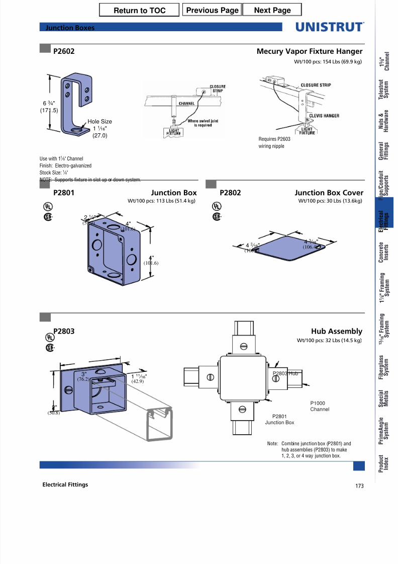
P2602 Mecury Vapor Fixture Hanger
6 3 ⁄ 4"
(171.5)
Hole Size
1 1 ⁄ 16"
(27.0)
Wt/100 pcs: 154 Lbs (69.9 kg)
Use with 15 ⁄ 8" Channel
Finish: Electro-galvanized
Stock Size: 1 ⁄ 4"
NOTE: Supports fixture in slot up or down system.
Junction Boxes
Requires P2603
wiring nipple
P2803 Hub AssemblyWt/100 pcs: 32 Lbs (14.5 kg)
1 11 ⁄ 16"3"
2"
(76.2)
(50.8)
(42.9)
2 1 ⁄ 4"4"
(101.6)
(57.2)
4"(101.6)
4 3 ⁄ 16"(106.4)4 3 ⁄ 16"
(106.4)
P2802 Junction Box CoverP2801 Junction BoxWt/100 pcs: 30 Lbs (13.6kg)Wt/100 pcs: 113 Lbs (51.4 kg)
Note: Combine junction box (P2801) andhub assemblies (P2803) to make1, 2, 3, or 4 way junction box.
P2801Junction Box
P2803 Hub
P1000Channel
Previous Page Next PageReturn to TOC

8/10/2019 Electrical Fittings Unistrut Construction
http://slidepdf.com/reader/full/electrical-fittings-unistrut-construction 14/22
174
®
Electrical Fittings
y
y
P2900 P2901
P2902 P2903
Wt/100 pcs: 35 Lbs (15.9 kg)
P1000
P1000
P1000
P1000
Wt/100 pcs: 45 Lbs (20.4 kg)Wt/100 pcs: 27 Lbs (12.2 kg)
Material: Cast aluminum.Material: Cast aluminum.
Material: Cast aluminum. Material: Cast aluminum.
Wt/100 pcs: 20 Lbs (9.1 kg)
In-Channel Joiners
P2904 Wt/100 pcs: 12 Lbs (5.4kg)
P3300, P4000,P4100
3 / 8"-16 x 1 / 4"Socket Cup Point
Set Screws Included
3 / 8"-16 x 1 / 4"Socket Cup Point
Set Screws Included
3 / 8"-16 x 1 / 4"
Socket Cup Point
Set Screws Included
3 / 8"-16 x 1 / 4"Socket Cup Point
Set Screws Included
3 / 8"-16 x 1 / 4"Socket Cup Point
Set Screws Included
Previous Page Next PageReturn to TOC
8/10/2019 Electrical Fittings Unistrut Construction
http://slidepdf.com/reader/full/electrical-fittings-unistrut-construction 15/22
175Electrical Fittings
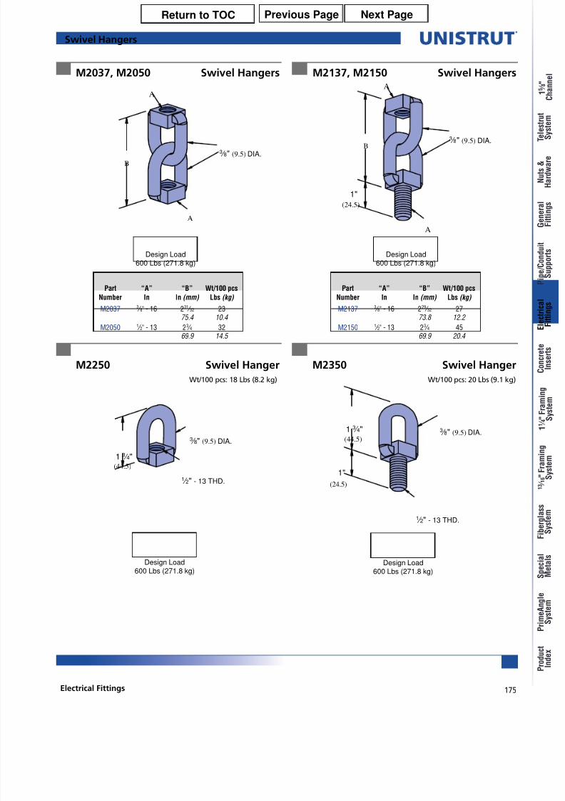
M2037, M2050 Swivel Hangers M2137, M2150 Swivel Hangers
M2250 Swivel Hanger M2350 Swivel Hanger
Wt/100 pcs: 18 Lbs (8.2 kg)
A
3 ⁄ 8" (9.5) DIA.
A
B
3 ⁄ 8" (9.5) DIA.
1 ⁄ 2" - 13 THD.
1 3 ⁄ 4"(44.5)
A
3 ⁄ 8" (9.5) DIA.
A
B
(24.5)
1"
3 ⁄ 8" (9.5) DIA.1 3 ⁄ 4"(44.5)
(24.5)
1"
1 ⁄ 2" - 13 THD.
Wt/100 pcs: 20 Lbs (9.1 kg)
Part “A” “B” Wt/100 pcs
Number In In (mm) Lbs (kg)
M2037 3 ⁄ 8" - 16 231 ⁄ 32 2375.4 10.4
M2050 1 ⁄ 2" - 13 23 ⁄ 4 3269.9 14.5
Part “A” “B” Wt/100 pcs
Number In In (mm) Lbs (kg)
M2137 3 ⁄ 8" - 16 229 ⁄ 32 2773.8 12.2
M2150 1 ⁄ 2" - 13 23 ⁄ 4 4569.9 20.4
Swivel Hangers
Design Load600 Lbs (271.8 kg)
Design Load600 Lbs (271.8 kg)
Design Load600 Lbs (271.8 kg)
Design Load600 Lbs (271.8 kg)
Previous Page Next PageReturn to TOC
8/10/2019 Electrical Fittings Unistrut Construction
http://slidepdf.com/reader/full/electrical-fittings-unistrut-construction 16/22
176
®
Electrical Fittings
y
y
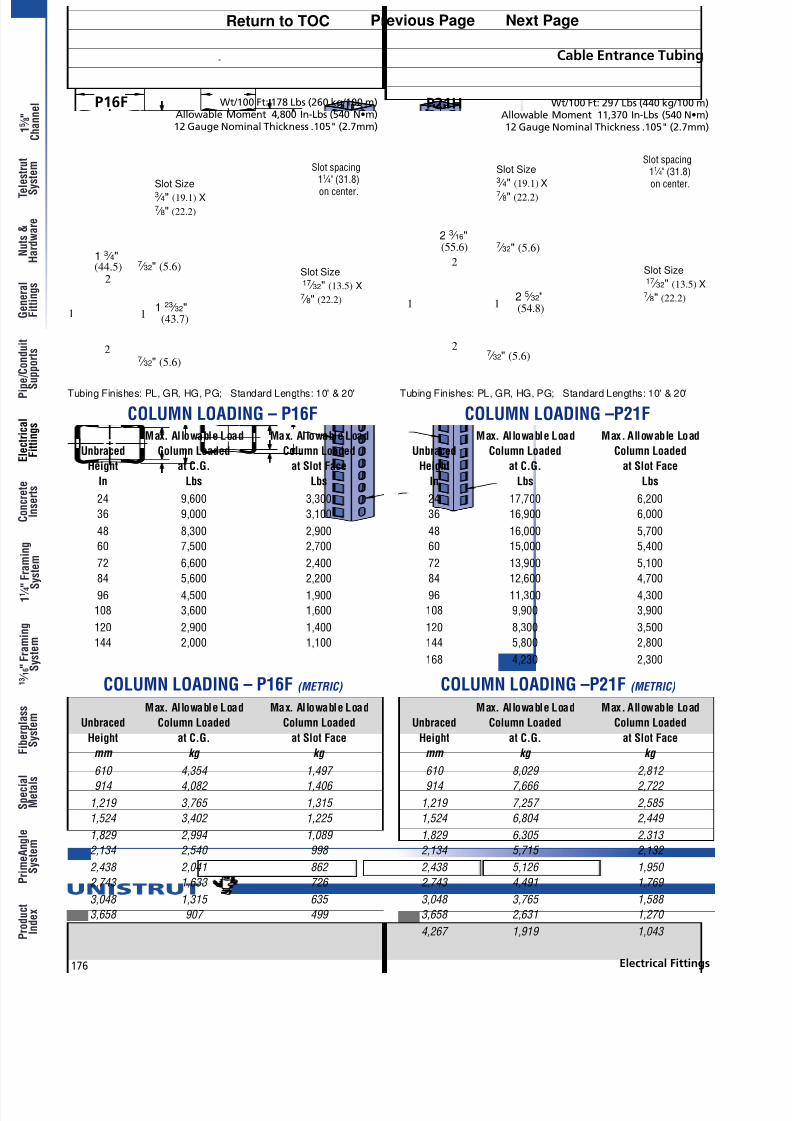
P16F P21H
Slot Size17 ⁄ 32" (13.5) X 7 ⁄ 8" (22.2)
Slot Size3 ⁄ 4" (19.1) X 7 ⁄ 8" (22.2)
Slot Size17 ⁄ 32" (13.5) X 7 ⁄ 8" (22.2)
Slot Size3 ⁄ 4" (19.1) X 7 ⁄ 8" (22.2)
11
2
27 ⁄ 32" (5.6)
7 ⁄ 32" (5.6)2 3 ⁄ 16"(55.6)
2 5 ⁄ 32"(54.8)
1
2
1
27 ⁄ 32" (5.6)
7 ⁄ 32" (5.6)1 3 ⁄ 4"(44.5)
1 23 ⁄ 32"(43.7)
Cable Entrance Tubing
Slot spacing11 ⁄ 4" (31.8)on center.
Slot spacing11 ⁄ 4" (31.8)
on center.
Max. Allowable Load Max. Allowable Load
Unbraced Column Loaded Column Loaded
Height at C.G. at Slot Face
In Lbs Lbs
24 9,600 3,300
36 9,000 3,100
48 8,300 2,900
60 7,500 2,700
72 6,600 2,400
84 5,600 2,20096 4,500 1,900
108 3,600 1,600
120 2,900 1,400
144 2,000 1,100
Max. Allowable Load Max. Allowable Load
Unbraced Column Loaded Column Loaded
Height at C.G. at Slot Face
mm kg kg
610 4,354 1,497 914 4,082 1,406
1,219 3,765 1,315
1,524 3,402 1,225
1,829 2,994 1,089
2,134 2,540 998
2,438 2,041 862
2,743 1,633 726
3,048 1,315 635
3,658 907 499
Max. Allowable Load Max. Allowable Load
Unbraced Column Loaded Column Loaded
Height at C.G. at Slot Face
In Lbs Lbs
24 17,700 6,200
36 16,900 6,000
48 16,000 5,700
60 15,000 5,400
72 13,900 5,100
84 12,600 4,70096 11,300 4,300
108 9,900 3,900
120 8,300 3,500
144 5,800 2,800
168 4,230 2,300
Max. Allowable Load Max. Allowable Load
Unbraced Column Loaded Column Loaded
Height at C.G. at Slot Face
mm kg kg
610 8,029 2,812 914 7,666 2,722
1,219 7,257 2,585
1,524 6,804 2,449
1,829 6,305 2,313
2,134 5,715 2,132
2,438 5,126 1,950
2,743 4,491 1,769
3,048 3,765 1,588
3,658 2,631 1,270
4,267 1,919 1,043
Wt/100 Ft: 178 Lbs (260 kg/100 m)Allowable Moment 4,800 In-Lbs (540 N•m)12 Gauge Nominal Thickness .105" (2.7mm)
Wt/100 Ft: 297 Lbs (440 kg/100 m)Allowable Moment 11,370 In-Lbs (540 N•m)12 Gauge Nominal Thickness .105" (2.7mm)
Tubing Finishes: PL, GR, HG, PG; Standard Lengths: 10' & 20' Tubing Finishes: PL, GR, HG, PG; Standard Lengths: 10' & 20'
COLUMN LOADING – P16F COLUMN LOADING –P21F
COLUMN LOADING – P16F (METRIC) COLUMN LOADING –P21F (METRIC)
Previous Page Next PageReturn to TOC
8/10/2019 Electrical Fittings Unistrut Construction
http://slidepdf.com/reader/full/electrical-fittings-unistrut-construction 17/22
177Electrical Fittings
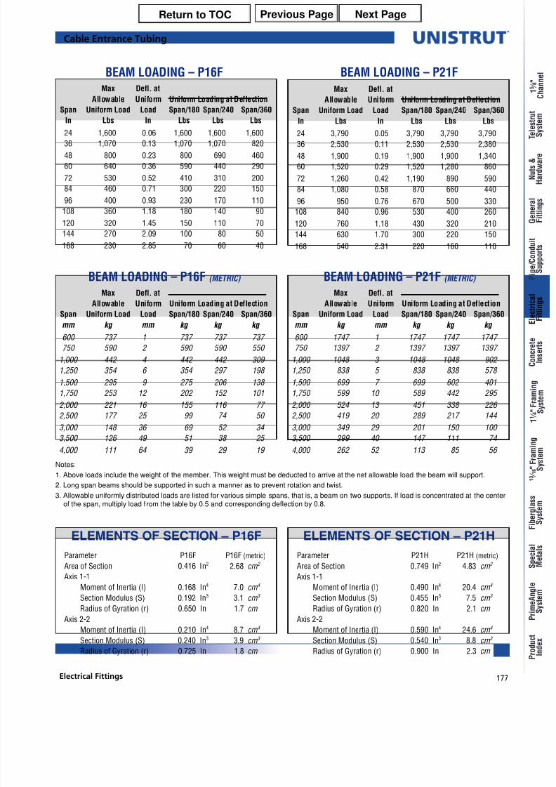
Cable Entrance Tubing
ELEMENTS OF SECTION – P16F
Parameter P16F P16F (metric)
Area of Section 0.416 In2 2.68 cm 2
Axis 1-1
Moment of Inertia (I) 0.168 In4 7.0 cm 4
Section Modulus (S) 0.192 In3 3.1 cm 3
Radius of Gyration (r) 0.650 In 1.7 cm
Axis 2-2
Moment of Inertia (I) 0.210 In4 8.7 cm 4
Section Modulus (S) 0.240 In3 3.9 cm 3
Radius of Gyration (r) 0.725 In 1.8 cm
Parameter P21H P21H (metric)
Area of Section 0.749 In2 4.83 cm 2
Axis 1-1
Moment of Inertia (I) 0.490 In4 20.4 cm 4
Section Modulus (S) 0.455 In3 7.5 cm 3
Radius of Gyration (r) 0.820 In 2.1 cm
Axis 2-2
Moment of Inertia (I) 0.590 In4 24.6 cm 4
Section Modulus (S) 0.540 In3 8.8 cm 3
Radius of Gyration (r) 0.900 In 2.3 cm
ELEMENTS OF SECTION – P21H
Notes:
1. Above loads include the weight of the member. This weight must be deducted to arrive at the net allowable load the beam will support.
2. Long span beams should be supported in such a manner as to prevent rotation and twist.
3. Allowable uniformly distributed loads are listed for various simple spans, that is, a beam on two supports. If load is concentrated at the centerof the span, multiply load from the table by 0.5 and corresponding deflection by 0.8.
Max Defl. at
Allowable Uniform Uniform Loading at Deflection
Span Uniform Load Load Span/180 Span/240 Span/360
In Lbs In Lbs Lbs Lbs
24 1,600 0.06 1,600 1,600 1,60036 1,070 0.13 1,070 1,070 820
48 800 0.23 800 690 460
60 640 0.36 590 440 290
72 530 0.52 410 310 200
84 460 0.71 300 220 150
96 400 0.93 230 170 110
108 360 1.18 180 140 90
120 320 1.45 150 110 70
144 270 2.09 100 80 50
168 230 2.85 70 60 40
Max Defl. at
Allowable Uniform Uniform Loading at Deflection
Span Uniform Load Load Span/180 Span/240 Span/360
mm kg mm kg kg kg
600 737 1 737 737 737
750 590 2 590 590 550
1,000 442 4 442 442 309
1,250 354 6 354 297 198
1,500 295 9 275 206 138
1,750 253 12 202 152 101
2,000 221 16 155 116 77 2,500 177 25 99 74 50
3,000 148 36 69 52 34
3,500 126 49 51 38 25
4,000 111 64 39 29 19
Max Defl. at
Allowable Uniform Uniform Loading at Deflection
Span Uniform Load Load Span/180 Span/240 Span/360
In Lbs In Lbs Lbs Lbs
24 3,790 0.05 3,790 3,790 3,79036 2,530 0.11 2,530 2,530 2,380
48 1,900 0.19 1,900 1,900 1,340
60 1,520 0.29 1,520 1,280 860
72 1,260 0.42 1,190 890 590
84 1,080 0.58 870 660 440
96 950 0.76 670 500 330
108 840 0.96 530 400 260
120 760 1.18 430 320 210
144 630 1.70 300 220 150
168 540 2.31 220 160 110
Max Defl. at
Allowable Uniform Uniform Loading at Deflection
Span Uniform Load Load Span/180 Span/240 Span/360
mm kg mm kg kg kg
600 1747 1 1747 1747 1747
750 1397 2 1397 1397 1397
1,000 1048 3 1048 1048 902
1,250 838 5 838 838 578
1,500 699 7 699 602 401
1,750 599 10 589 442 295
2,000 524 13 451 338 226 2,500 419 20 289 217 144
3,000 349 29 201 150 100
3,500 299 40 147 111 74
4,000 262 52 113 85 56
BEAM LOADING – P16F BEAM LOADING – P21F
BEAM LOADING – P16F (METRIC) BEAM LOADING – P21F (METRIC)
Previous Page Next PageReturn to TOC
8/10/2019 Electrical Fittings Unistrut Construction
http://slidepdf.com/reader/full/electrical-fittings-unistrut-construction 18/22
178
®
Electrical Fittings
y
y
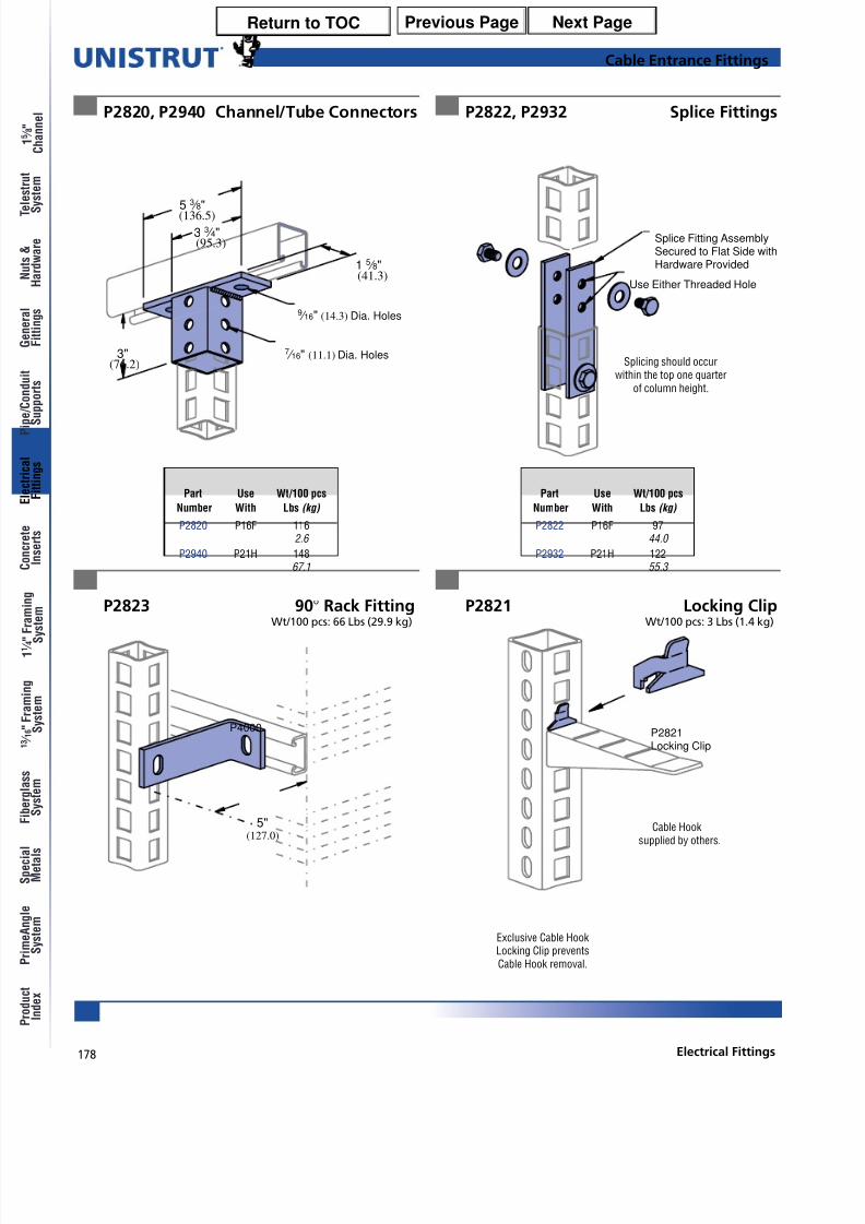
Cable Entrance Fittings
P2822, P2932 Splice Fittings
P2823 90° Rack FittingWt/100 pcs: 66 Lbs (29.9 kg)
P2821 Locking ClipWt/100 pcs: 3 Lbs (1.4 kg)
Splicing should occurwithin the top one quarter
of column height.
Exclusive Cable HookLocking Clip preventsCable Hook removal.
P2821Locking Clip
3"(76.2)
53 ⁄
8"(136.5)
3 3 ⁄ 4"(95.3)
1 5 ⁄ 8"(41.3)
9 ⁄ 16" (14.3) Dia. Holes
7 ⁄ 16" (11.1) Dia. Holes
P2820, P2940 Channel/Tube Connectors
Cable Hook
supplied by others.(127.0)
5"
P4000
Splice Fitting AssemblySecured to Flat Side withHardware Provided
Use Either Threaded Hole
Part Use Wt/100 pcs
Number With Lbs (kg)
P2820 P16F 1162.6
P2940 P21H 14867.1
Part Use Wt/100 pcs
Number With Lbs (kg)
P2822 P16F 9744.0
P2932 P21H 12255.3
Previous Page Next PageReturn to TOC

8/10/2019 Electrical Fittings Unistrut Construction
http://slidepdf.com/reader/full/electrical-fittings-unistrut-construction 19/22
179Electrical Fittings
Cable Entrance Fittings
P2928, P2929 and P2930 Cable Brackets
P2920 thru P2924 Cable Brackets
L
A
1 5 ⁄ 8"(41.3)
B
3 ⁄ 16" (4.8) x 3 ⁄ 4" (19.1) Slots
2 3 ⁄ 4" (69.9) on Center
L
A
1 5 ⁄ 8"(41.3)
B
Safety factor of 3.
Safety factor of 3.
Material: 12 gauge steel.
Material: 12 gauge steel.
Use with P16F or P21H.
Use with P16F or P21H.
UniformPart Wt/100 pcs Design Load
Number “L” “A” “B” Lbs (kg) Lbs (kg)
P2928 6 31 ⁄ 2 7 ⁄ 8 92 500152.4 88.9 22.2 41.7 2.2
P2929 12 31 ⁄ 2 15 ⁄ 8 320 250304.8 88.9 41.3 145.1 1.1
P2930 18 31 ⁄ 2 15 ⁄ 8 420 170457.2 88.9 41.3 190.5 0.8
UniformPart Wt/100 pcs Design Load
Number “L” “A” “B” Lbs (kg) Lbs (kg)
P2920 51
⁄ 2 31
⁄ 27
⁄ 8 90 500139.7 88.9 22.2 40.8 2.2
P2921 81 ⁄ 4 31 ⁄ 2 7 ⁄ 8 120 325209.6 88.9 22.2 54.4 1.4
P2922 11 31 ⁄ 2 15 ⁄ 8 300 275279.4 88.9 41.3 136.1 1.2
P2923 133 ⁄ 4 31 ⁄ 2 15 ⁄ 8 340 220349.3 88.9 41.3 154.2 1.0
P2924 191 ⁄ 4 31 ⁄ 2 15 ⁄ 8 430 160489.0 88.9 41.3 195.0 0.7
Previous Page Next PageReturn to TOC
8/10/2019 Electrical Fittings Unistrut Construction
http://slidepdf.com/reader/full/electrical-fittings-unistrut-construction 20/22
180
®
Electrical Fittings
y
y
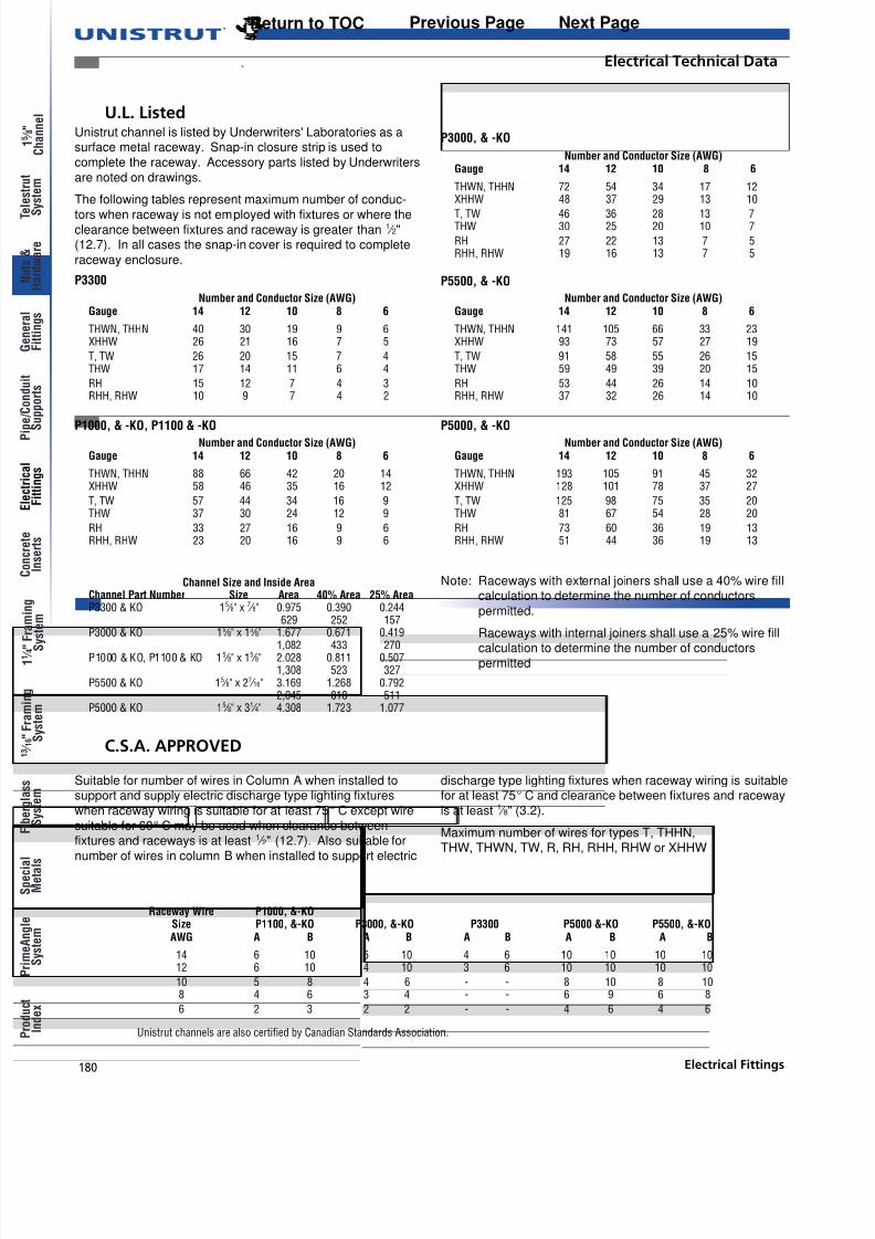
U.L. Listed
C.S.A. APPROVED
Electrical Technical Data
Unistrut channels are also certified by Canadian Standards Association.
Unistrut channel is listed by Underwriters' Laboratories as asurface metal raceway. Snap-in closure strip is used to
complete the raceway. Accessory parts listed by Underwriters
are noted on drawings.
The following tables represent maximum number of conduc-
tors when raceway is not employed with fixtures or where theclearance between fixtures and raceway is greater than 1
⁄ 2"(12.7). In all cases the snap-in cover is required to complete
raceway enclosure.
P3300
P3000, & -KO
P5500, & -KO
P5000, & -KOP1000, & -KO, P1100 & -KO
Suitable for number of wires in Column A when installed tosupport and supply electric discharge type lighting fixtures
when raceway wiring is suitable for at least 75° C except wire
suitable for 60° C may be used when clearance betweenfixtures and raceways is at least 1
⁄ 2" (12.7). Also suitable for
number of wires in column B when installed to support electric
Number and Conductor Size (AWG)Gauge 14 12 10 8 6
THWN, THHN 72 54 34 17 12XHHW 48 37 29 13 10
T, TW 46 36 28 13 7THW 30 25 20 10 7
RH 27 22 13 7 5RHH, RHW 19 16 13 7 5
Number and Conductor Size (AWG)Gauge 14 12 10 8 6
THWN, THHN 141 105 66 33 23XHHW 93 73 57 27 19
T, TW 91 58 55 26 15THW 59 49 39 20 15
RH 53 44 26 14 10RHH, RHW 37 32 26 14 10
Number and Conductor Size (AWG)Gauge 14 12 10 8 6
THWN, THHN 40 30 19 9 6XHHW 26 21 16 7 5
T, TW 26 20 15 7 4THW 17 14 11 6 4
RH 15 12 7 4 3RHH, RHW 10 9 7 4 2
Number and Conductor Size (AWG)Gauge 14 12 10 8 6
THWN, THHN 88 66 42 20 14XHHW 58 46 35 16 12
T, TW 57 44 34 16 9THW 37 30 24 12 9
RH 33 27 16 9 6RHH, RHW 23 20 16 9 6
Number and Conductor Size (AWG)Gauge 14 12 10 8 6
THWN, THHN 193 105 91 45 32XHHW 128 101 78 37 27
T, TW 125 98 75 35 20THW 81 67 54 28 20
RH 73 60 36 19 13RHH, RHW 51 44 36 19 13
Raceway Wire P1000, &-KOSize P1100, &-KO P3000, &-KO P3300 P5000 &-KO P5500, &-KOAWG A B A B A B A B A B
14 6 10 5 10 4 6 10 10 10 1012 6 10 4 10 3 6 10 10 10 10
10 5 8 4 6 - - 8 10 8 108 4 6 3 4 - - 6 9 6 8
6 2 3 2 2 - - 4 6 4 6
discharge type lighting fixtures when raceway wiring is suitablefor at least 75° C and clearance between fixtures and raceway
is at least 1 ⁄ 8" (3.2).
Maximum number of wires for types T, THHN,
THW, THWN, TW, R, RH, RHH, RHW or XHHW
Channel Size and Inside AreaChannel Part Number Size Area 40% Area 25% AreaP3300 & KO 15 ⁄ 8" x 7 ⁄ 8" 0.975 0.390 0.244
629 252 157P3000 & KO 15 ⁄ 8" x 13 ⁄ 8" 1.677 0.671 0.419
1,082 433 270P1000 & KO, P1100 & KO 15 ⁄ 8" x 15 ⁄ 8" 2.028 0.811 0.507
1,308 523 327P5500 & KO 15 ⁄ 8" x 27 ⁄ 16" 3.169 1.268 0.792
2,045 818 511P5000 & KO 15 ⁄ 8" x 31 ⁄ 4" 4.308 1.723 1.077
Note: Raceways with external joiners shall use a 40% wire fillcalculation to determine the number of conductors
permitted.
Raceways with internal joiners shall use a 25% wire fillcalculation to determine the number of conductors
permitted
Previous Page Next PageReturn to TOC

8/10/2019 Electrical Fittings Unistrut Construction
http://slidepdf.com/reader/full/electrical-fittings-unistrut-construction 21/22
181Electrical Fittings
Fluorescent Fixtures - Support Applications
Electrical Technical Data
Spring-Nut attachment systemSlotted channel attachment system
Conduit connects through knockout in fixture. Fixtureis supported by P1006-1420 spring nut and 1/4" round
head machine screw. Assembly is supported by
P2855 hinged hanger.
Conduit connects through knockout in fixture. Fixture is
supported by HCSS series hex bolt and hex nut. Raceway
is supported by P2855 hanger. To splice a continuous run,use P3922.
Recommended Support Spacing for Fixtures
Deflections are based on continuity of span and use of 4 ft.fixtures weighing approximately 30 lbs. each. Do not use joiner
fittings between supporting hangers. When using knock-out or
slotted channels deflections will be increased approximately5%. With fixtures spaced 2' - 0" apart, deflection is 60-70% of
table. When spaced 4' - 0" apart, deflection is 50-60% of table.
Distance Between Supports8' (2.4m) 10' (3m) 12' (3.7m) 14' (4.3m) 16' (4.9m) 18' (5.5m) 20' (6.1m) 22' (6.7m) 24' (7.3m)
Channel In (mm) In (mm) In (mm) In (mm) In (mm) In (mm) In (mm) In (mm) In (mm)
P3300 0.1874.7
P3000 0.100 0.250 0.5002.5 6.4 12.7
P1100 0.088 0.250 0.437 0.8752.2 6.4 11.1 22.2
P1000 0.180 0.312 0.625 1.000 1.6254.6 7.9 15.9 25.4 41.3
P5500 0.250 0.500 0.812 1.6206.4 12.7 20.6 41.1
P5000 0.310 0.625 1.000 1.800 2.5007.9 15.9 25.4 45.7 63.5
P1001 0.310 0.625 1.000 1.800 2.5007.9 15.9 25.4 45.7 63.5
P5001 0.200 0.250 0.400 0.5005.1 6.4 10.2 12.7
Deflection Table
Previous Page Next PageReturn to TOC
8/10/2019 Electrical Fittings Unistrut Construction
http://slidepdf.com/reader/full/electrical-fittings-unistrut-construction 22/22
®
y
y
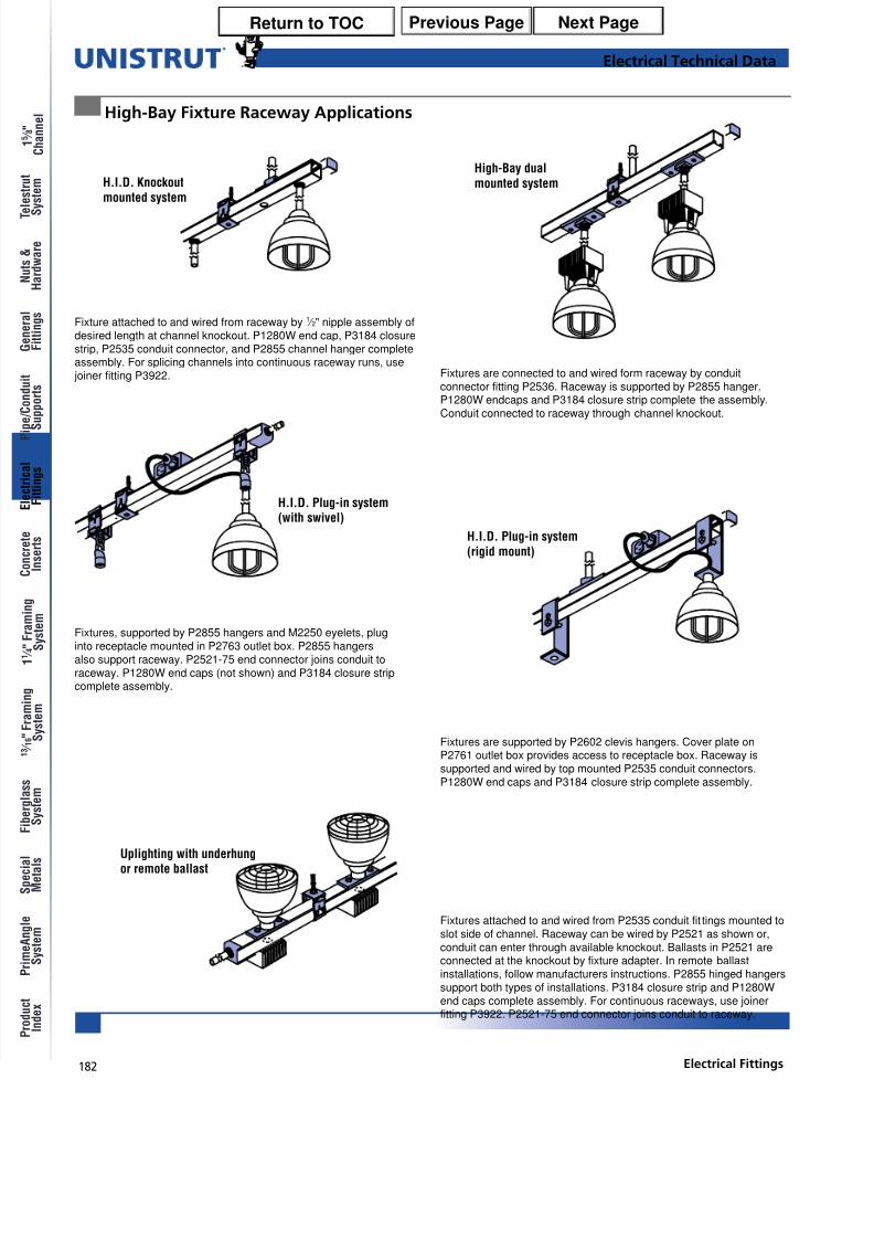
High-Bay Fixture Raceway Applications
Fixtures are supported by P2602 clevis hangers. Cover plate onP2761 outlet box provides access to receptacle box. Raceway issupported and wired by top mounted P2535 conduit connectors.P1280W end caps and P3184 closure strip complete assembly.
Fixture attached to and wired from raceway by 1 ⁄ 2" nipple assembly of
desired length at channel knockout. P1280W end cap, P3184 closurestrip, P2535 conduit connector, and P2855 channel hanger completeassembly. For splicing channels into continuous raceway runs, use joiner fitting P3922.
Fixtures, supported by P2855 hangers and M2250 eyelets, pluginto receptacle mounted in P2763 outlet box. P2855 hangersalso support raceway. P2521-75 end connector joins conduit toraceway. P1280W end caps (not shown) and P3184 closure stripcomplete assembly.
Fixtures are connected to and wired form raceway by conduitconnector fitting P2536. Raceway is supported by P2855 hanger.P1280W endcaps and P3184 closure strip complete the assembly.Conduit connected to raceway through channel knockout.
Uplighting with underhungor remote ballast
High-Bay dualmounted systemH.I.D. Knockout
mounted system
H.I.D. Plug-in system(rigid mount)
H.I.D. Plug-in system(with swivel)
Fixtures attached to and wired from P2535 conduit fit tings mounted toslot side of channel. Raceway can be wired by P2521 as shown or,conduit can enter through available knockout. Ballasts in P2521 areconnected at the knockout by fixture adapter. In remote ballastinstallations, follow manufacturers instructions. P2855 hinged hangerssupport both types of installations. P3184 closure strip and P1280Wend caps complete assembly. For continuous raceways, use joinerfitting P3922. P2521-75 end connector joins conduit to raceway.
Electrical Technical Data
Previous Page Next PageReturn to TOC


