Download - Electromagnetic Energy (“EME”)

TELNET, INC. | 7630 STANDISH PLACE, ROCKVILLE, MD 20855 | P:301-840-7110 ext. 61062 or 61608 F:301-840-0162 | WWW.TELNET-INC.COM
Site Information
Site No.: DC03XC264
Building Name: L’ENFANT PLAZA
Address: 451 7TH STREET SW.
WASHINGTON, DC 20410
Survey Date: 07/31/2018 Report Date: 8/10/2018
Surveyed By: Erik Brainard Site Type: Rooftop
Electromagnetic Energy (“EME”) Measurement and Site Compliance Report

P a g e | 2
TELNET, INC. | 7630 STANDISH PLACE, ROCKVILLE, MD 20855 | P:301-840-7110 ext. 61062 or 61608 F:301-840-0162 | WWW.TELNET-INC.COM
Sprint
Site No.: DC03XC264 - Site Name: L’ENFANT PLAZA
Electromagnetic Energy (“EME”) Measurement and Site Compliance Report
451 7TH STREET SW, Washington, DC 20410
P a g e | 3
TELNET, INC. | 7630 STANDISH PLACE, ROCKVILLE, MD 20855 | P:301-840-7110 ext. 61062 or 61608 F:301-840-0162 | WWW.TELNET-INC.COM
TABLE OF CONTENT
1 SUMMARY ............................................................................................................... 4
1.1 INTRODUCTION ................................................................................................... 4 1.2 STATEMENT OF COMPLIANCE ............................................................................ 4
1.3 SAFETY RECOMMENDATIONS & SITE COMPLIANCE ACTIONS .......................... 5 1.3.1 Safety procedures recommendations: ............................................................ 7 1.3.1.1 General Site Work: .................................................................................... 7 1.3.1.2 EME Awareness Training: ......................................................................... 7
1.3.1.3 Site Access Control: ................................................................................... 7 1.3.1.4 RF signage: ................................................................................................ 7 1.3.1.5 Active Antennas and Keeping proper distance: ......................................... 7
1.4 ANTENNA SITE AREA MEASUREMENTS ............................................................. 8
1.5 RF MODELING .................................................................................................. 10
2 SITE CONFIGURATION ...................................................................................... 12
2.1 ANTENNA INVENTORY ...................................................................................... 13
3 PHOTOS OF ANTENNA SITE AREA AND ANTENNAS .............................. 14
3.1 SPRINT EXISTING SECTORS ............................................................................ 14
3.2 OTHER CARRIER’S ANTENNAS ........................................................................ 16 3.3 SIGNS AND ACCESS TO THE SITE .................................................................... 17
4 MODELING SUMMARY AND ASSUMPTIONS .............................................. 18
4.1.1 General Model Assumptions ........................................................................ 18 4.1.2 Use of Generic Antennas ............................................................................. 18
5 SURVEY METHODOLOGY ................................................................................ 18
5.1 SAMPLING DESCRIPTION ................................................................................. 18
6 ANALYSIS AND COMPUTATION ..................................................................... 19
6.1 ANALYSIS ......................................................................................................... 19
7 FCC LIMITS FOR MPE ........................................................................................ 20
7.1 (A) LIMITS FOR OCCUPATIONAL/CONTROLLED EXPOSURE .......................... 20 7.2 (B) LIMITS FOR GENERAL POPULATION/UNCONTROLLED EXPOSURE .......... 21
7.3 CONTROLLED AND UNCONTROLLED EXPOSURE LIMITS ................................. 21
8 FCC STANDARD CERTIFICATION .................................................................. 22
9 DISCLAIMER ......................................................................................................... 22
10 GLOSSARY OF TERMS ................................................................................. 23
11 APPENDIX ......................................................................................................... 24

P a g e | 4
TELNET, INC. | 7630 STANDISH PLACE, ROCKVILLE, MD 20855 | P:301-840-7110 ext. 61062 or 61608 F:301-840-0162 | WWW.TELNET-INC.COM
1 Summary
1.1 Introduction
There are RF, NTIA and unlicensed spectrum transmitting antennas installed at the following location (the “wireless telecommunications facility”):
Street Address: 451 7TH STREET SW, Washington, DC 20410
Site No.: DC03XC264
Latitude / Longitude: 38.883597°/ -77.022569°
Telnet, Inc performed an RF emission survey of the RF environment surrounding the facilities installed by Sprint at this location. The facility is located on a eight-story building. The physical survey verified antenna placement and technical specifications for accurate recommendations to determine compliance with FCC guidelines. Antenna specifications presented herein are based on direct evidence from an antenna or transmitter cabinet, information from the site manager or building manager, information from the licensees, educated estimates by the field technician or a combination of some or all of these sources.
1.2 Statement of Compliance
After evaluation of the total RF emission levels from all the operators and a thorough review of the site access procedures, signage and observable antenna locations, Telnet has determined that:
This site will be compliant with FCC Policy if the changes outlined in section 1.3 are implemented. The compliance determination is based on General Public MPE levels due to predicted and measured levels based on Spatial Averaging, RF signage placement, and the level of restricted access to the antennas at the site.
P a g e | 5
TELNET, INC. | 7630 STANDISH PLACE, ROCKVILLE, MD 20855 | P:301-840-7110 ext. 61062 or 61608 F:301-840-0162 | WWW.TELNET-INC.COM
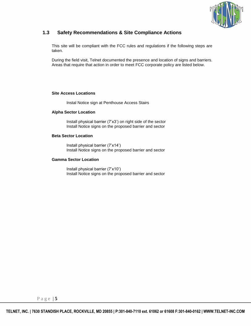
1.3 Safety Recommendations & Site Compliance Actions
This site will be compliant with the FCC rules and regulations if the following steps are taken. During the field visit, Telnet documented the presence and location of signs and barriers. Areas that require that action in order to meet FCC corporate policy are listed below.
Site Access Locations
Instal Notice sign at Penthouse Access Stairs
Alpha Sector Location
Install physical barrier (7’x3’) on right side of the sector Install Notice signs on the proposed barrier and sector
Beta Sector Location
Install physical barrier (7’x14’) Install Notice signs on the proposed barrier and sector
Gamma Sector Location
Install physical barrier (7’x10’) Install Notice signs on the proposed barrier and sector

P a g e | 6
TELNET, INC. | 7630 STANDISH PLACE, ROCKVILLE, MD 20855 | P:301-840-7110 ext. 61062 or 61608 F:301-840-0162 | WWW.TELNET-INC.COM
21
0 ft
Roof
202122
19
Roof
Roof
RoofRoof
Roof
RoofRoof
Penthouse
Penthouse
12
56
78
91018
11121314
151617
A
B
C
AT&TVERIZONSPRINT T-M OBILE M ETRO PCS CRICKET UNKNOWNCAR RIER ANTENNA:
TELNET, INC., 7630 Standish Plac e, Rockv ille, M D 20855; Phone: 888 -883-5638 / Fax : 301-840-0162; Web: www .Telnet -Inc.com
34
STAIRS
Figure 1 Proposed Rooftop Drawing
Sector A
Install physical barrier (7’x3’) on right side of the sector Install Notice signs on the
proposed barrier and sector
Sector B
Install physical barrier (7’x14’)
Install Notice signs on the proposed barrier
and sector
Sector C
Install physical barrier (7’x10’)
Install Notice signs on the proposed barrier
and sector
Install Notice sign at Penthouse Access Stairs
P a g e | 7
TELNET, INC. | 7630 STANDISH PLACE, ROCKVILLE, MD 20855 | P:301-840-7110 ext. 61062 or 61608 F:301-840-0162 | WWW.TELNET-INC.COM
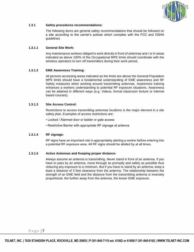
1.3.1 Safety procedures recommendations:
The following items are general safety recommendations that should be followed on
a site according to the carrier’s polices which complies with the FCC and OSHA
guidelines
1.3.1.1 General Site Work:
Any maintenance workers obliged to work directly in front of antennas and / or in areas
indicated as above 100% of the Occupational MPE limits should coordinate with the
wireless operators to turn off transmitters during their work period.
1.3.1.2 EME Awareness Training:
All persons accessing areas indicated as the limits are above the General Population
MPE limits should have a fundamental understanding of EME awareness and RF
Safety measures when working around transmitting antennas. Awareness training
enhances a workers understanding to potential RF exposure situations. Awareness
can be attained in different ways (e.g. Videos, formal classroom lecture or internet
based courses).
1.3.1.3 Site Access Control:
Restrictions to access transmitting antennas locations is the major element in a site
safety plan. Examples of access restrictions are:
• Locked / Alarmed door or ladder or gate access
• Restrictive Barrier with appropriate RF signage at antenna
1.3.1.4 RF signage:
RF signs have an important role in appropriately alerting a worker before entering into
a potential RF exposure area. All RF signs should be abided by at all times.
1.3.1.5 Active Antennas and Keeping proper distance:
Always assume an antenna is transmitting. Never stand in front of an antenna. If you
have to pass by an antenna, move through as promptly and safely as possible thus
reducing any exposure to a minimum. But if you have to stand by an antenna, keep a
least a distance of 3 feet clearance from the antenna. The relationship between the
strength of an EME field and the distance from the transmitting antenna is inversely
proportional, the further away from the antenna, the lesser EME exposure.

P a g e | 8
TELNET, INC. | 7630 STANDISH PLACE, ROCKVILLE, MD 20855 | P:301-840-7110 ext. 61062 or 61608 F:301-840-0162 | WWW.TELNET-INC.COM
1.4 Antenna Site Area Measurements
The site survey crew has provided the sketch of the site location with a visual representation of the RF environment at the site and depicts antenna locations and site structures. Figure 2 depicts the surveyed measurements in percentage of MPE limits for General Population standards. Percentages greater than 100% exceed the FCC MPE limits. Section 1.4 contains actual spatially averaged MPE measured at each reference point.
Figure 2 represents the actual readings at various points at the site. These measurements depict the energy levels that can be encountered by an individual at the site.
Maximum value for Occupational Standard based on Spatial Averaging: 26.96% Maximum value for General Population Standard based on Spatial Averaging: 134.8%
Result Summary: Sprint will be Compliant with FCC Policy based on General Public Maximum Permissible Exposure, if changes in section 1.3 are implemented.

P a g e | 9
TELNET, INC. | 7630 STANDISH PLACE, ROCKVILLE, MD 20855 | P:301-840-7110 ext. 61062 or 61608 F:301-840-0162 | WWW.TELNET-INC.COM
210
ft
Roof
202122
19
Roof
Roof
RoofRoof
Roof
RoofRoof
Penthouse
Penthouse
12
3456
78
91018
11121314
151617
A
B
C
AT&TVERIZONSPRINT T-M OBILE M ETRO PCS CRICKET UNKNOWNCAR RIER ANTENNA:
TELNET, INC., 7630 Standish Plac e, Rockv ille, M D 20855; Phone: 888 -883-5638 / Fax : 301-840-0162; Web: www .Telnet-Inc.com
Roof
0.8680.780
1.300
5.101
0.691
4.931
0.7460.762
0.8142
0.987
0.8011 1.214
1.4340.8011
4.329 0.869
26.96
23.28
2.669
6.93
2.006
1.78
Figure 2 Numbers in Blue are the Percentage (%) of MPE Limits for General Population Standard

P a g e | 10
TELNET, INC. | 7630 STANDISH PLACE, ROCKVILLE, MD 20855 | P:301-840-7110 ext. 61062 or 61608 F:301-840-0162 | WWW.TELNET-INC.COM
1.5 RF Modeling
The modeling calculations assume that the antennas are operating at 100% capacity; that all antenna channels are transmitting simultaneously and that the radio transmitters are operating at full power. Obstructions (trees, buildings etc) that would normally attenuate the signal are not taken into account. As a result, the predicted signal levels are more conservative (higher) than the actual signal levels will be from the measurement conclusions.
••
••
••
••
••
•
•
•
•
•
•
•
••
••
•
•
• ••
••
• ••
••
•
210
ft
Max Sprint Simulation Level 306.5%
Roof
202122
19
Roof
Roof
RoofRoof
Roof
RoofRoof
Penthouse
Penthouse
12
3456
78
91018
11121314
151617
A
B
C
AT&TVERIZONSPRINT T-M OBILE M ETRO PCS CRICKET UNKNOWNCAR RIER ANTENNA:
TELNET, INC., 7630 Standish Plac e, Rockv ille, M D 20855; Phone: 888 -883-5638 / Fax : 301-840-0162; Web: www .Telnet-Inc.com Figure 3
Percent of FCC General Population Exposure Limit contributed by All Carriers at Penthouse levels
0% - 100% MPE ≥ 5000% MPE100% - 500% MPE 500% - 5000% MPE

P a g e | 11
TELNET, INC. | 7630 STANDISH PLACE, ROCKVILLE, MD 20855 | P:301-840-7110 ext. 61062 or 61608 F:301-840-0162 | WWW.TELNET-INC.COM
••
••
••
••
••
•
•
•
•
•
•
•
••
••
•
•
• ••
••
• ••
••
•
210
ft
Max Sprint Simulation Level 18.4%
Roof
202122
19
Roof
Roof
RoofRoof
Roof
RoofRoof
Penthouse
Penthouse
12
3456
78
91018
11121314
151617
A
B
C
AT&TVERIZONSPRINT T-M OBILE M ETRO PCS CRICKET UNKNOWNCAR RIER ANTENNA:
TELNET, INC., 7630 Standish Plac e, Rockv ille, M D 20855; Phone: 888 -883-5638 / Fax : 301-840-0162; Web: www .Telnet-Inc.com Figure 4
Percent of FCC General Population Exposure Limit contributed by All Carriers at Roof level
0% - 100% MPE ≥ 5000% MPE100% - 500% MPE 500% - 5000% MPE

P a g e | 12
TELNET, INC. | 7630 STANDISH PLACE, ROCKVILLE, MD 20855 | P:301-840-7110 ext. 61062 or 61608 F:301-840-0162 | WWW.TELNET-INC.COM
2 Site Configuration
A survey was performed on July 31, 2018 to determine the RF emission levels present at the site. Measurements were performed on the areas considered accessible to the occupational population. At this site, additional steps were taken to assess areas accessible to the general population. The results of the measurements were the combined energy levels of all antennas. To measure the RF emissions within the vicinity, Telnet, Inc, utilized NARDA E Field Probe Model 25C, Frequency Range 300 KHz - 50 GHz with NARDA Electromagnetic Survey Meter Model NBM-550. Calibration was performed by Narda Safety Test Solutions on June 05, 2018 for a total interval of 24 month. Relevant administrative and compliance–related information about the antenna site area is summarized in the table below:
Site Access
Access Method Door
Access to Keys Yes
Door Locked Yes
Collocation Status Colocated
Site Area Classification General Population
Weather Conditions Cloudy
P a g e | 13
TELNET, INC. | 7630 STANDISH PLACE, ROCKVILLE, MD 20855 | P:301-840-7110 ext. 61062 or 61608 F:301-840-0162 | WWW.TELNET-INC.COM
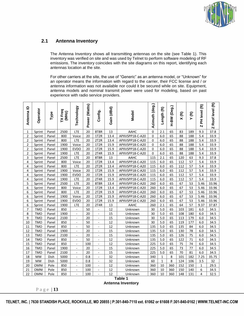
2.1 Antenna Inventory
The Antenna Inventory shows all transmitting antennas on the site (see Table 1). This inventory was verified on site and was used by Telnet to perform software modeling of RF emissions. The inventory coincides with the site diagrams on this report, identifying each antennas location at the site. For other carriers at the site, the use of “Generic” as an antenna model, or “Unknown” for an operator means the information with regard to the carrier, their FCC license and / or antenna information was not available nor could it be secured while on site. Equipment, antenna models and nominal transmit power were used for modeling, based on past experience with radio service providers.
An
ten
na
ID
Op
era
tor
Ty
pe
TX
Fre
q
(MH
z)
Te
ch
no
log
y
Po
wer
(Wa
tts
)
Co
nfi
g.
Ga
in (
dB
d)
Mo
de
l
Azim
uth
(d
eg
.)
Le
ng
th (
ft)
H-B
W (
De
g.)
X (
ft)
Y (
ft)
Z P
H l
ev
el (f
t)
Z R
oo
f le
ve
l (f
t)
1 Sprint Panel 2500 LTE 20 8T8R 13 AAHC 0 2.1 65 83 189 9.3 37.8 2 Sprint Panel 800 Voice 20 1T2R 13.4 APXVSPP18-C-A20 0 6.0 65 88 188 5.4 33.9 2 Sprint Panel 800 LTE 20 2T2R 13.4 APXVSPP18-C-A20 0 6.0 65 88 188 5.4 33.9 2 Sprint Panel 1900 Voice 20 1T2R 15.9 APXVSPP18-C-A20 0 6.0 65 88 188 5.4 33.9 2 Sprint Panel 1900 EVDO 20 1T2R 15.9 APXVSPP18-C-A20 0 6.0 65 88 188 5.4 33.9 2 Sprint Panel 1900 LTE 20 2T4R 15.9 APXVSPP18-C-A20 0 6.0 65 88 188 5.4 33.9 3 Sprint Panel 2500 LTE 20 8T8R 13 AAHC 115 2.1 65 120 63 9.3 37.8 4 Sprint Panel 800 Voice 20 1T2R 13.4 APXVSPP18-C-A20 115 6.0 65 112 57 5.4 33.9 4 Sprint Panel 800 LTE 20 2T2R 13.4 APXVSPP18-C-A20 115 6.0 65 112 57 5.4 33.9 4 Sprint Panel 1900 Voice 20 1T2R 15.9 APXVSPP18-C-A20 115 6.0 65 112 57 5.4 33.9 4 Sprint Panel 1900 EVDO 20 1T2R 15.9 APXVSPP18-C-A20 115 6.0 65 112 57 5.4 33.9 4 Sprint Panel 1900 LTE 20 2T4R 15.9 APXVSPP18-C-A20 115 6.0 65 112 57 5.4 33.9 5 Sprint Panel 2500 LTE 20 8T8R 13.4 APXVSPP18-C-A20 260 6.0 65 67 53 5.46 33.96 6 Sprint Panel 800 Voice 20 1T2R 13.4 APXVSPP18-C-A20 260 6.0 65 67 53 5.46 33.96 6 Sprint Panel 800 LTE 20 2T2R 15.9 APXVSPP18-C-A20 260 6.0 65 67 53 5.46 33.96 6 Sprint Panel 1900 Voice 20 1T2R 15.9 APXVSPP18-C-A20 260 6.0 65 67 53 5.46 33.96 6 Sprint Panel 1900 EVDO 20 1T2R 15.9 APXVSPP18-C-A20 260 6.0 65 67 53 5.46 33.96 6 Sprint Panel 1900 LTE 20 2T4R 13 AAHC 260 2.1 65 64 57 9.37 37.87 7 TMO Panel 850 - 50 - 12 Unknown 30 5.0 65 103 181 6.0 34.5 8 TMO Panel 1900 - 20 - 15 Unknown 30 5.0 65 108 180 6.0 34.5 9 TMO Panel 2100 - 20 - 15 Unknown 30 5.0 65 113 179 6.0 34.5
10 TMO Panel 850 - 50 - 12 Unknown 30 5.0 65 119 177 6.0 34.5 11 TMO Panel 850 - 50 - 12 Unknown 135 5.0 65 135 84 6.0 34.5 12 TMO Panel 1900 - 20 - 15 Unknown 135 5.0 65 130 78 6.0 34.5 13 TMO Panel 2100 - 20 - 15 Unknown 135 5.0 65 126 75 6.0 34.5 14 TMO Panel 850 - 50 - 12 Unknown 135 5.0 65 122 71 6.0 34.5 15 TMO Panel 850 - 100 - 12 Unknown 225 5.0 65 75 74 6.0 34.5 16 TMO Panel 1900 - 20 - 15 Unknown 225 5.0 65 73 77 6.0 34.5 17 TMO Panel 2100 - 20 - 15 Unknown 225 5.0 65 70 81 6.0 34.5 18 MW Dish 5000 - 0.8 - 32 Unknown 340 1 8 101 182 7.25 35.75 19 MW DIsh 5000 - 0.8 - 32 Unknown 60 1 8 124 106 3.5 32 20 OMNI Pole 850 - 100 - 12 Unknown 360 10 360 152 150 1 29.5 21 OMNI Pole 850 - 100 - 12 Unknown 360 10 360 150 140 6 34.5 22 OMNI Pole 850 - 100 - 12 Unknown 360 10 360 148 131 4 32.5
Table 1 Antenna Inventory

P a g e | 14
TELNET, INC. | 7630 STANDISH PLACE, ROCKVILLE, MD 20855 | P:301-840-7110 ext. 61062 or 61608 F:301-840-0162 | WWW.TELNET-INC.COM
3 Photos of Antenna Site Area and Antennas
3.1 Sprint Existing Sectors
Sprint Antennas # 1, 2 Sprint Antennas # 1, 2
Sprint Antennas # 3, 4 Sprint Antennas # 3, 4

P a g e | 15
TELNET, INC. | 7630 STANDISH PLACE, ROCKVILLE, MD 20855 | P:301-840-7110 ext. 61062 or 61608 F:301-840-0162 | WWW.TELNET-INC.COM
Sprint Antennas # 5, 6 Sprint Antennas # 5, 6
P a g e | 16
TELNET, INC. | 7630 STANDISH PLACE, ROCKVILLE, MD 20855 | P:301-840-7110 ext. 61062 or 61608 F:301-840-0162 | WWW.TELNET-INC.COM
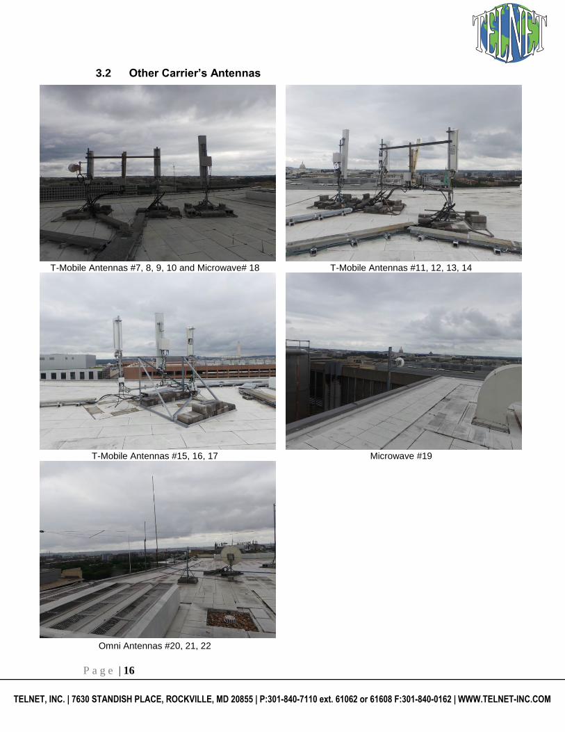
3.2 Other Carrier’s Antennas
T-Mobile Antennas #7, 8, 9, 10 and Microwave# 18 T-Mobile Antennas #11, 12, 13, 14
T-Mobile Antennas #15, 16, 17 Microwave #19
Omni Antennas #20, 21, 22

P a g e | 17
TELNET, INC. | 7630 STANDISH PLACE, ROCKVILLE, MD 20855 | P:301-840-7110 ext. 61062 or 61608 F:301-840-0162 | WWW.TELNET-INC.COM
3.3 Signs and Access to the Site
Required RF signs include an information sign and all access locations were checked. Pictures below show the access ladder, the hatch and the signage at the site.
Access Stairs to Roof Roof Access Door with Notice sign
Sector A with Notice sign
P a g e | 18
TELNET, INC. | 7630 STANDISH PLACE, ROCKVILLE, MD 20855 | P:301-840-7110 ext. 61062 or 61608 F:301-840-0162 | WWW.TELNET-INC.COM
4 Modeling Summary and Assumptions
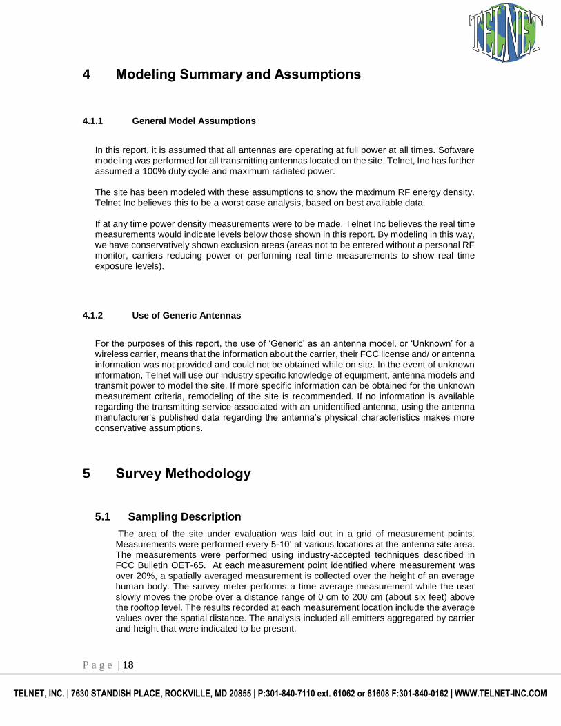
4.1.1 General Model Assumptions
In this report, it is assumed that all antennas are operating at full power at all times. Software modeling was performed for all transmitting antennas located on the site. Telnet, Inc has further assumed a 100% duty cycle and maximum radiated power.
The site has been modeled with these assumptions to show the maximum RF energy density. Telnet Inc believes this to be a worst case analysis, based on best available data.
If at any time power density measurements were to be made, Telnet Inc believes the real time measurements would indicate levels below those shown in this report. By modeling in this way, we have conservatively shown exclusion areas (areas not to be entered without a personal RF monitor, carriers reducing power or performing real time measurements to show real time exposure levels).
4.1.2 Use of Generic Antennas
For the purposes of this report, the use of ‘Generic’ as an antenna model, or ‘Unknown’ for a wireless carrier, means that the information about the carrier, their FCC license and/ or antenna information was not provided and could not be obtained while on site. In the event of unknown information, Telnet will use our industry specific knowledge of equipment, antenna models and transmit power to model the site. If more specific information can be obtained for the unknown measurement criteria, remodeling of the site is recommended. If no information is available regarding the transmitting service associated with an unidentified antenna, using the antenna manufacturer’s published data regarding the antenna’s physical characteristics makes more conservative assumptions.
5 Survey Methodology
5.1 Sampling Description
The area of the site under evaluation was laid out in a grid of measurement points. Measurements were performed every 5-10’ at various locations at the antenna site area. The measurements were performed using industry-accepted techniques described in FCC Bulletin OET-65. At each measurement point identified where measurement was over 20%, a spatially averaged measurement is collected over the height of an average human body. The survey meter performs a time average measurement while the user slowly moves the probe over a distance range of 0 cm to 200 cm (about six feet) above the rooftop level. The results recorded at each measurement location include the average values over the spatial distance. The analysis included all emitters aggregated by carrier and height that were indicated to be present.

P a g e | 19
TELNET, INC. | 7630 STANDISH PLACE, ROCKVILLE, MD 20855 | P:301-840-7110 ext. 61062 or 61608 F:301-840-0162 | WWW.TELNET-INC.COM
6 Analysis and Computation
Based on emission patterns of the antennas at this location most of the energy emitted is spread towards the horizon. This assumes the antennas have a zero downtilt. If a mechanical downtilt other then zero is applied to the antennas then the maximum energy emitted will need to be calculated using the information below. The following formulas can be used for calculating the power density. Power density is calculated by dividing the surface area of the sphere or the unit area normal to the direction of the propagation. This information is usually shown in units of microwatts per square centimeter (uW/cm2), milliwatt per square centimeters (mW/cm2), or watts per square meter (W/m2).
6.1 Analysis
P a g e | 20
TELNET, INC. | 7630 STANDISH PLACE, ROCKVILLE, MD 20855 | P:301-840-7110 ext. 61062 or 61608 F:301-840-0162 | WWW.TELNET-INC.COM
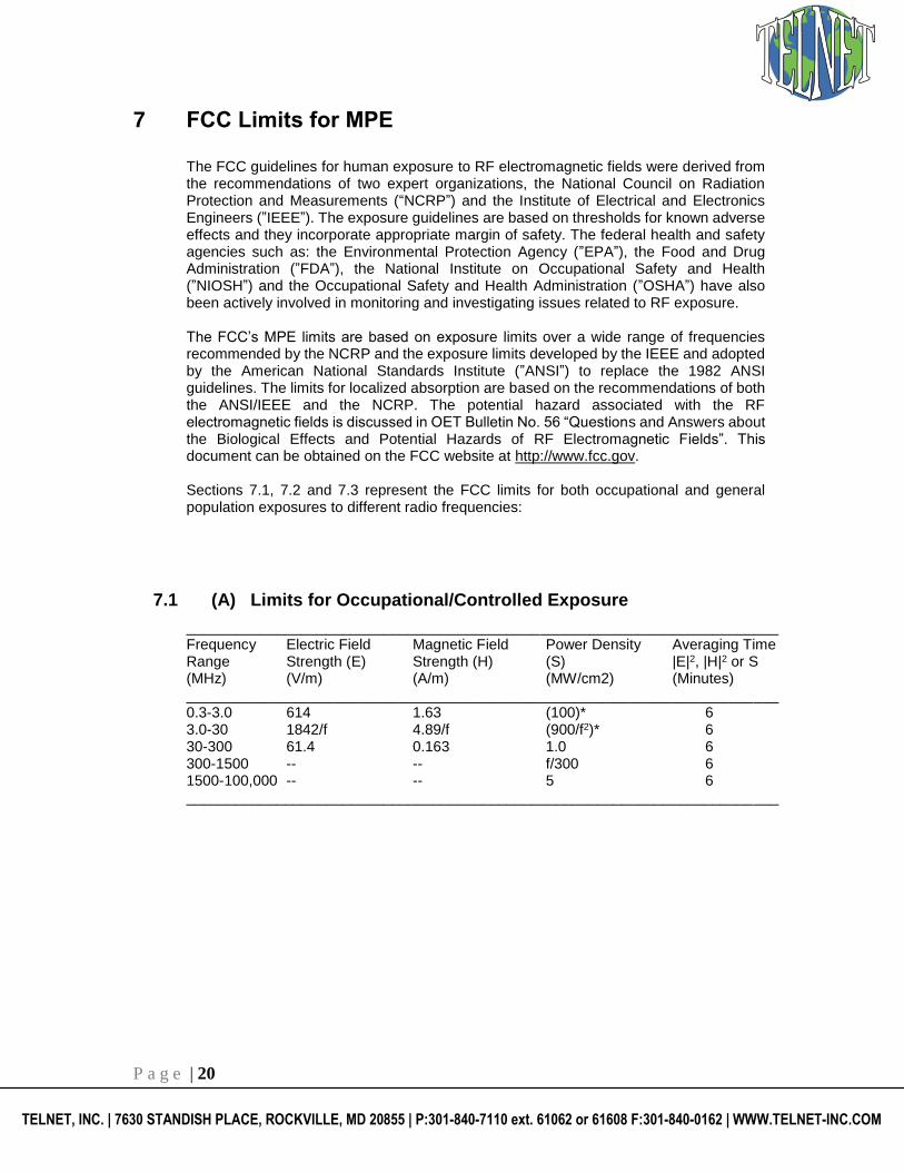
7 FCC Limits for MPE
The FCC guidelines for human exposure to RF electromagnetic fields were derived from the recommendations of two expert organizations, the National Council on Radiation Protection and Measurements (“NCRP”) and the Institute of Electrical and Electronics Engineers (”IEEE”). The exposure guidelines are based on thresholds for known adverse effects and they incorporate appropriate margin of safety. The federal health and safety agencies such as: the Environmental Protection Agency (”EPA”), the Food and Drug Administration (”FDA”), the National Institute on Occupational Safety and Health (”NIOSH”) and the Occupational Safety and Health Administration (”OSHA”) have also been actively involved in monitoring and investigating issues related to RF exposure. The FCC’s MPE limits are based on exposure limits over a wide range of frequencies recommended by the NCRP and the exposure limits developed by the IEEE and adopted by the American National Standards Institute (”ANSI”) to replace the 1982 ANSI guidelines. The limits for localized absorption are based on the recommendations of both the ANSI/IEEE and the NCRP. The potential hazard associated with the RF electromagnetic fields is discussed in OET Bulletin No. 56 “Questions and Answers about the Biological Effects and Potential Hazards of RF Electromagnetic Fields”. This document can be obtained on the FCC website at http://www.fcc.gov. Sections 7.1, 7.2 and 7.3 represent the FCC limits for both occupational and general population exposures to different radio frequencies:
7.1 (A) Limits for Occupational/Controlled Exposure
________________________________________________________________________ Frequency Electric Field Magnetic Field Power Density Averaging Time Range Strength (E) Strength (H) (S) |E|2, |H|2 or S (MHz) (V/m) (A/m) (MW/cm2) (Minutes) ________________________________________________________________________ 0.3-3.0 614 1.63 (100)* 6 3.0-30 1842/f 4.89/f (900/f2)* 6 30-300 61.4 0.163 1.0 6 300-1500 -- -- f/300 6 1500-100,000 -- -- 5 6 ________________________________________________________________________

P a g e | 21
TELNET, INC. | 7630 STANDISH PLACE, ROCKVILLE, MD 20855 | P:301-840-7110 ext. 61062 or 61608 F:301-840-0162 | WWW.TELNET-INC.COM
7.2 (B) Limits for General Population/Uncontrolled Exposure
________________________________________________________________________ Frequency Electric Field Magnetic Field Power Density Averaging Time Range Strength (E) Strength (H) (S) |E|2, |H|2 or S (MHz) (V/m) (A/m) (MW/cm2) (Minutes) ________________________________________________________________________ 0.3-1.34 614 1.63 (100)* 30 1.34-30 824/f 2.19/f (180/f2)* 30 30-300 27.5 0.073 0.2 30 300-1500 -- -- f/1500 30 1500-100,000 -- -- 1.0 30 ________________________________________________________________________ f = frequency in MHz *Plane-wave equivalent power density
NOTE 1: Occupational/controlled limits apply in situations in which persons are exposed as a consequence of their employment provided those persons are fully aware of the potential for exposure and can exercise control over their exposure. Limits for occupational/controlled exposure also apply in situations when an individual is transient through a location where occupational/controlled limits apply provided he or she is made aware of the potential for exposure. NOTE 2: General population/uncontrolled exposures apply in situations in which the general public may be exposed, or in which persons that are exposed as a consequence of their employment may not be fully aware of the potential for exposure or can not exercise control over their exposure.
7.3 Controlled and Uncontrolled Exposure Limits

P a g e | 22
TELNET, INC. | 7630 STANDISH PLACE, ROCKVILLE, MD 20855 | P:301-840-7110 ext. 61062 or 61608 F:301-840-0162 | WWW.TELNET-INC.COM
8 FCC Standard Certification
This report certifies that the site DC03XC264 – L’ENFANT PLAZA will be in compliance with the FCC standard if the required changes outlined in section 1.3 are implemented. The analysis and procedure used to provide the report is according to FCC OET Bulletin 65 and other industry standards.
Prepared by:
Ayush Shukla 08/10/2018
RF Engineer
Telnet Inc.
Reviewed by:
Ahmed Al Jobouri 08/13/2018
RF Engineer
Telnet Inc.
9 Disclaimer
This report is based on information provided to Telnet Inc., information gathered at the site and prior experience when complete information is unavailable. Should the site change or change or more accurate information becomes available, please contact Telnet Inc. to create a new RF Safety plan. Recommendations in this report can be materially affected by inaccuracies and changes in RF environment at the site. This report is related only to RF Safety issues. If the recommendations in this report conflict with any other safety procedures, contact Telnet Inc. and the party responsible for the conflicting procedures so that they can be resolved. Telnet Inc. cannot assume any responsibility for failure to properly follow the elements in the RF safety program, but can assist in implementing all items in the RF safety plan as recommended by OSHA.

P a g e | 23
TELNET, INC. | 7630 STANDISH PLACE, ROCKVILLE, MD 20855 | P:301-840-7110 ext. 61062 or 61608 F:301-840-0162 | WWW.TELNET-INC.COM
10 Glossary of Terms
1. Electromagnetic Field (energy density) – the electromagnetic energy contained in an infinitesimal volume divided by that volume.
2. Exposure – Exposure occurs whenever and wherever a person is subjected to electric, magnetic or electromagnetic fields other than those originating from physiological processes in the body and other natural phenomena.
3. General Population / Uncontrolled Exposure – applies to human exposure to RF fields when the general public is exposed or in which persons who are exposed as a consequence of their employment may not be made fully aware of the potential for exposure or cannot exercise control over their exposure. Therefore, members of the general public always fall under this category when exposure is not employment-related.
4. Maximum Permissible Exposure (MPE) – the rms and peak electric and magnetic field strength, their squares, or the plane-wave equivalent power densities associated with these fields to which a person may be exposed without harmful effect and with an acceptable safety factor.
5. Occupational / Controlled Exposure – applies to human exposure to RF fields when persons are exposed as a consequence of their employment and in which those persons who are exposed have been made fully aware of the potential for exposure and can exercise control over their exposure. Occupational/controlled exposure limits also apply where exposure is of a transient nature as a result of incidental passage through a location where exposure levels may be above general population/controlled limits.
6. Power Density (S) – Power per unit area normal to the direction of propagation, usually
expressed in units of watts per square meter (W/m2) or, for convenience, units such as
milliwatts per square centimeter (mW/cm2) or microwatts per square centimeter
(μW/cm2).
7. Ionization – a process by which electrons are stripped from atoms and molecules. This process can produce molecular changes that can lead to damage in biological tissue, includes effect on DNA, the genetic material. This process requires interaction with high levels of electromagnetic energy.
8. Non-Ionizing radiation – a type of emission that is not great enough to cause ionization of atom and molecules. “RF and Microwave Emissions” are low-level energy which is not capable of ionization.

P a g e | 24
TELNET, INC. | 7630 STANDISH PLACE, ROCKVILLE, MD 20855 | P:301-840-7110 ext. 61062 or 61608 F:301-840-0162 | WWW.TELNET-INC.COM
11 Appendix

P a g e | 25
TELNET, INC. | 7630 STANDISH PLACE, ROCKVILLE, MD 20855 | P:301-840-7110 ext. 61062 or 61608 F:301-840-0162 | WWW.TELNET-INC.COM


