
NASA/CR-2000-210297
Electromagnetic Field Penetration Studies
M. D. Deshpande
NYMA, Inc., Hampton, Virginia
June 2000
https://ntrs.nasa.gov/search.jsp?R=20000080278 2020-05-09T20:28:29+00:00Z

The NASA STI Program Office... in Profile
Since its founding, NASA has been dedicated
to the advancement of aeronautics and spacescience. The NASA Scientific and Technical
Information (STI) Program Office plays a key
part in helping NASA maintain this
important role.
The NASA STI Program Office is operated by
Langley Research Center, the lead center forNASA's scientific and technical information.
The NASA STI Program Office provides
access to the NASA STI Database, the
largest collection of aeronautical and space
science STI in the world. The Program Officeis also NASA's institutional mechanism for
disseminating the results of its research and
development activities. These results are
published by NASA in the NASA STI Report
Series, which includes the following report
types:
• TECHNICAL PUBLICATION. Reports of
completed research or a major significant
phase of research that present the results
of NASA programs and include extensive
data or theoretical analysis. Includes
compilations of significant scientific andtechnical data and information deemed
to be of continuing reference value. NASA
counterpart of peer-reviewed formal
professional papers, but having less
stringent limitations on manuscript
length and extent of graphic
presentations.
• TECHNICAL MEMORANDUM.
Scientific and technical findings that are
preliminary or of specialized interest,
e.g., quick release reports, working
papers, and bibliographies that containminimal annotation. Does not contain
extensive analysis.
• CONTRACTOR REPORT. Scientific and
technical findings by NASA-sponsored
contractors and grantees.
CONFERENCE PUBLICATION.
Collected papers from scientific and
technical conferences, symposia,
seminars, or other meetings sponsored or
co-sponsored by NASA.
SPECIAL PUBLICATION. Scientific,
technical, or historical information from
NASA programs, projects, and missions,
often concerned with subjects having
substantial public interest.
TECHNICAL TRANSLATION. English-
language translations of foreign scientific
and technical material pertinent toNASA's mission.
Specialized services that complement the
STI Program Office's diverse offerings include
creating custom thesauri, building customized
databases, organizing and publishing
research results.., even providing videos.
For more information about the NASA STI
Program Office, see the following:
• Access the NASA STI Program Home
Page at httpY/www.sti.nasa.gov
• Email your question via the Internet to
• Fax your question to the NASA STI
Help Desk at (301) 621-0134
• Telephone the NASA STI Help Desk at(301) 621-0390
Write to:
NASA STI Help Desk
NASA Center for AeroSpace Information7121 Standard Drive
Hanover, MD 21076-1320

NASA/CR-2000-210297
Electromagnetic Field Penetration Studies
M. D. Deshpande
NYMA, Inc., Hampton, Virginia
National Aeronautics and
Space Administration
Langley Research Center
Hampton, Virginia 23681-2199
Prepared for Langley Research Centerunder Contract NAS1-96013
June 2000

Available from:
NASA Center for AeroSpace Information (CASI)7121 Standard Drive
Hanover, MD 21076-1320
(301) 621-0390
National Technical Information Service (NTIS)
5285 Port Royal Road
Springfield, VA 22161-2171(703) 605-6000

Contents
List of Figures
List of SymbolsAbstract
1. Introduction
2. Formulation of Problem
2.1 Electromagnetic Field Outside Enclosure
2.1.1 Electromagnetic Field Due to Incident Field
2.1.2 Electromagnetic Field Scattered Due to Apertures
2.2 Electromagnetic Field Inside Enclosure
2.2.1 Electromagnetic Field Due to Aperture on z = 0 Plane
2.2.2 Electromagnetic Field Due to Aperture on z = c Plane
2.3 Derivation of Integral Equation
2.3.1 Integral Equation for Apertures on z = 0 Plane
2.3.2 Integral Equation for Apertures on z = c Plane
3. Numerical Results & Discussions
3.1 Single Aperture Case
3.2 Two or Multi Apertures Case
3.3 EM Field Penetration Inside B-757Aircraft Configuration
3.4 Convergence Test for Large Size Cavities
4. Conclusion
Acknowledgement
References
Appendix I
Appendix II
Appendix III
Appendix IV
2
5
9
10
12
15
15
16
19
20
23
26
26
30
35
35
41
47
55
60
61
61
62
62
63
63

Figure1
Figure2
Figure3.1
Figure3.2
Figure4
Figure5
Figure6
List of Figures
Geometry of rectangular enclosure with rectangular apertures illuminated by a
plane wave at normal incidence.
Geometry of equivalent problem with apertures replaced by magnetic current
sources.
Electric field shielding at the center of (30. x 12. x 30.) cm 3 enclosure with (10. x
0.5) cm 2 aperture located at (15.6.) cm in z = 0 plane with dominant cavity
mode considered.
Electric field shielding at the center of (30. x 12. x 30.) cm 3 enclosure with (10.
x 0.5) cm 2 aperture located at (15.6.) cm in z = 0 plane with dominant and
higher order cavity mode considered.
Electric field shielding at the center of (30. x 12. x 30.) cm 3 enclosure with (20.
x 3.0) cm 2 aperture located at (15.6.0) cm in z = 0 plane with dominant cavity
mode considered.
Electric field shielding at the center of (30. x 12. x 30.) cm 3 enclosure with (20.
x 3.0) cm 2 aperture located at (15.6.) cm in z = 0 plane with dominant and
higher order cavity mode considered.
Electric field shielding at the center of (30. x 12. x 30.) cm 3 enclosure with (20.
x 3.0) cm 2 aperture located at (15.6.0)cm in z = 0 plane with two aperture
modes considered.

Figure7 Electricfield shieldingatthecenterof (30.x 12.x 30.)cm3enclosurewith (10.
x 3.0)cm2aperturelocatedat ( 15.,6.0)cm in z = 0 planewith threeaperture
modesconsidered.
Figure8 Electricfield shieldingatthecenterof (30.x 12.x 30.)cm3enclosurewith two
identicalapertureswith (20.x 3.0)cm2size. Apertureonelocatedat ( 15.,6.,
0.0)cm,andaperturetwo locatedat (15.,6., 30.)cm.
Figure9 Effectof higherorderaperturemodesonelectricfield shieldingat thecenterof
(30.x 12.x 30.)cm3enclsourewith two identicalaperturesof size(20.x 3.0)
cm2 .Apertureonelocatedat ( 15.,6.,0.0)cm, andaperturetwo locatedat ( 15.,
6., 30.)cm.
Figure10 Electricfield shieldingof rectangularenclosureof size(30x 12x 30 ) cm3with
two identicalrectangularapertures(oneoneachside)of varioussizeswhenillu-
minatedby incidentplanewaveatnormal incidence.Comparisonwith FEM/
MoM calculation.
Figure11 Rectangularcavitywith four identicalaperturesandilluminatedby planewave
with normalincidence.All dimensionsin cm.
Figure12 Electricfield shieldingof rectangularcavity shownin Figure11. Observation
point ( 30,6, 15)cm.Comparisonwith FEM/MoM calculation.
Figure13 Geometryof B-757aircraftconfigurationwith crosssectionalandlongitudinal
approximatedcrosssection.
Figure14(a)ClosedrectangularcavityapproximatingaB-757fuselagewith rectangularaper-
tureson sidewalls representingpassengerwindows.
Figure14(b)ClosedrectangularcavityapproximatingaB-757fuselagewith tworectangular

Figure15
Figure16
Figure17
Figure18
Figure19
aperturesonsidewalls representingpassengerwindows.
Electricfield shielding(for verticalpolarization)of arectangularcavity for verti-
calpolarizationapproximatingfuselageof aB-757 aircraft. Twowindowson
eachsideof cavitywereconsidered.Cavitysize( 3600.x 400.x 400.)cm3,win-
dow size( 25.x 35.) cm2,window locations(1800, 200.,0.0)cm,and(1800,
200.,400.)cm,field locationpoint ( 1800, 120, 200.)cm.
Electricfield shielding(for verticalpolarization)of arectangularcavityapproxi-
matingfuselageof aB-757 aircraftwhentwo aperturemodeswereconsidered.
Twowindowsoneachsideof cavitywereconsidered.Dimensionsof cavity,
apertureandfield point areasgivenin Figure 15.
Electricfield shielding(for verticalpolarization)of arectangularcavityapproxi-
matingfuselageof aB-757aircraftwhenthreeaperturemodeswereconsidered.
Twowindowsoneachsideof cavitywereconsidered.Dimensionsof cavity,
apertureandfield point areasgivenin Figure 15.
Electricfield shielding(for horizontalpolarization)of arectangularcavity
approximatingfuselageof aB-757aircraft. Twowindowsoneachsideof cavity
wereconsidered.Dimensionsof cavity,apertureandtheir locationsareasgiven
in Figure15.
Electricfield amplitudeat ( 2700.,300.,300.)cminsidearectangularcavityof
size( 5400.x 600.x 600.)cm3illuminatedby planewaveatnormalincidence
throughrectangularwindows(25.x 35.)cm2asafunctionof cavitymodeindex
n. Otherparameters:cavitymodeindexm = 1200,frequency= 2.87510864
GHz.
4

Figure20
Figure21
Electricfield amplitudeat ( 2700.,300.,300.)cminsidearectangularcavityof
size( 5400.x 600.x 600.)cm3illuminatedby planewaveatnormalincidence
throughrectangularwindows(25.x 35.)cmaasafunctionof cavitymodeindex
m. Otherparameters:cavitymodeindexn = 200,frequency= 2.87510864
Electricfield amplitudeat ( 2700.,300.,300.)cminsidearectangularcavityof
size( 5400.x 600.x 600.)cm3illuminatedby planewaveatnormalincidence
throughrectangularwindows(25.x 35.)cmaasafunctionof numberof aperture
modes.Otherparameters:cavitymodeindexn = 200,m = 1200, frequency=
2.87510864GHz GHz.
a
Arpq
b
B rpq
--)Ei
--)
Eapt
E (Mrl)
--)IF
-->HF
f HX
F Hy
List of Symbols
x-dimension of rectangular cavity/approximate length of fuselage
thcomplex modal amplitude of pq mode for aperture on z = c plane
(for x-directed aperture field)
y-dimension of rectangular cavity/approximate height of fuselage
thcomplex modal amplitude of pq mode for aperture on z = c plane
(for y-directed aperture field)
z-dimension of cavity/approximate width of fuselage
incident electric field
tangential aperture electric field
.-.->
electric field due to M,-1 in region I
-.-> --->
electric field due to Mrl and Mr2 in region II
---)
electric field due to Mr2 in region III
electric vector potential for region I
electric vector potential for region II
x-component of electric vector potential
y-component of electric vector potential

/'j'!XX
Gmyy
-->Hi
dyadic Green's function for rectangular enclosure
x-component of dyadic Green's function
y-component of dyaduc Green's function
incident magnetic field
HO i
HO,
(Hxi, Hyi, Hzi)
0 component of incident magnetic field
0 component of incident magnetic field
x-, y-, and z- component of incident magnetic field
--->
magnetic field due to M,-1 in region I
---> --->magnetic field due to Mrl and M,-2 in region II
--->III --->
H (M,-2)
II II II
Hx, Hy, H_
Ir'p'q'xi
I r'p'q'yi
I
J
ko
k I
kx,
L r
--.->
Mapt
--..)Mrl
--->Mr2
(m, n)
(P, q)
R
Urpq
---->
magnetic field due to Mr2 in region III
-->H --->
rectangular components of vector H (M,-)
coupling of testing function with x- component of incident magnetic field
coupling of testing function with y- component of incident magnetic field
unit dyadic
free-space wave number
propagation constant
wave numbers in x-, y-, and z-directions, respectively
thx-dimension of r aperture/window
equivalent magnetic current on aperture
equivalent magnetic current for apertures on z = 0 plane
equivalent magnetic current for apertures on z = c plane
mode index numbers used for cavity modes
integers used for aperture modes
number of apertures on each side
thcomplex modal amplitude of pq mode for aperture on z = 0 plane
(for x-directed aperture field)

Vrpq
W r
^ ^
X, y
(Xrc, Yrc, Zrc)
(x, y, z)
_xlxl
rpqr'p'q'
xlylY rpqr'p'q'
xly2Y rpqr'p'q'
_xlx2
rpqr'p'q'
ylxlY rpqr'p'q'
ylylY rpqr'p'q'
yly2Y rpqr'p'q'
ylx2Y rpqr'p'q'
_x2xl
rpqr'p'q'
x2y 1Y rpqr'p'q'
x2y2Y rpqr'p'q'
_Fx2x2
rpqr'p'q'
y2xlY rpqr'p'q'
y2ylY rpqr'p'q'
y2y2Y rpqr'p'q'
thcomplex modal amplitude of pq mode for aperture on z = 0 plane
thy-dimension of r aperture
unit vectors along x- and y-directions, respectively
thcoordinates of center point of r aperture
coordinates of a point in the rectangular coordinate system
mutual admittance between x-components of currents on z = 0 plane
mutual coupling between x- and y-components of currents on z = 0 plane
mutual coupling between x- component of currents on z = 0 plane and y-
component of current on z = c plane.
mutual coupling between x- component of currents on z = 0 plane and x-
component of current on z = c plane.
mutual admittance between y- and x-components of currents on z = 0 plane
mutual coupling between x- component of currents on z = 0 plane
mutual coupling between y- component of currents on z = 0 plane and y-
component of current on z = c plane.
mutual coupling between y- component of currents on z = 0 plane and x-
component of current on z = c plane.
mutual admittance between x-component of currents on z = c plane and x-
component of current on z = 0 plane
mutual coupling between x- component of currents on z = c plane and y-
component of current on z = 0 plane
mutual coupling between x- and y-components of currents on z = c plane
mutual coupling between x- components of currents on z = c plane
mutual admittance between y-component of currents on z = c plane and x-
component of current on z = 0 plane
mutual coupling between y- component of currents on z = c plane and y-
component of current on z = 0 plane
mutual coupling between y-components of currents on z = c plane

y2x2Yrpqr'p'q' mutual coupling between y- and x-components of currents on z = c plane
OPrpq
_rpq
Orpqy
ltYrpqx
^ ^
(Oi, Oi)
(Oi, _i)
EOm
_0
lao
0)
8(. )V
(p, q)fh modal function for r fh
(p, q)fh modal function for r fh
Fourier transform of _,.pq
Fourier transform of _rpq
unit vectors in 0 -and 0 -directions
angle of incident plane wave
Neumann's number
permittivity of free space
permeability of free- space
angular frequency
Kronecker delta function
gradient operator
aperture for y-directed magnetic current
aperture for x-directed magnetic current

AbstractA numerical method is presented to determine electromagnetic shielding
effectiveness of rectangular enclosure with apertures on its wall used for input and output
connections, control panels, visual-access windows, ventilation panels, etc. Expressing
electromagnetic fields in terms of cavity Green's function inside the enclosure and the free
space Green's function outside the enclosure, integral equations with aperture tangential
electric fields as unknown variables are obtained by enforcing the continuity of tangential
electric and magnetic fields across the apertures. Using the Method of Moments, the integral
equations are solved for unknown aperture fields. From these aperture fields, the
electromagnetic fields inside a rectangular enclosure due to external electromagnetic sources
are determined.
Numerical results on electric field shielding of a rectangular cavity with a
thin rectangular slot obtained using the present method are compared with the results obtained
using simple the transmission line technique for code validation. The present technique is
applied to determine field penetration inside a Boeing -757 by approximating its passenger
cabin as a rectangular cavity filled with a homogeneous medium and its passenger windows
by rectangular apertures. Preliminary results for, two windows; one on each side of fuselage
were considered. Numerical results on electromagnetic field penetration through passenger
windows of a Boeing -757 at frequencies 26 MHz, 171-175 MHz, and 428-432 MHz are
presented.

1.0 IntroductionApertures of various sizes and shapes on a metallic enclosure are used for reasons such as
input and output connections, control panels, visual-access windows, ventilation panels, etc.
Since these apertures at appropriate electromagnetic (EM) frequencies behave as very efficient
antennas, they also become sources of electromagnetic interference (EMI) problems for both EM
emission and susceptibility. It is important to know the EM shielding effectiveness of these
enclosures in presence of the apertures. The EM shielding effectiveness study may also help in
locating these apertures at proper places to reduce the EM emission or improving the immunity
of electronic components present inside the metallic enclo sure [1]- [5]
Shielding effectiveness can be calculated using numerical or analytical methods. Numeri-
cal methods such as the Finite Difference Time Domain (FDTD) method [6], and the hybrid
Finite Element/Method of Moments [7] can model complex structures inside enclosure but often
requires large computing time and memory. For electrically large size enclosures and apertures
these methods, though more accurate, become difficult for designers to use to investigate effects
of EM shielding on the design parameters.
Pure analytical formulations described in [3]-[5] even though provide a much faster means
of calculating shielding effectiveness are based on various simplifying assumptions whose valid-
ity may be questionable at high frequencies.
In the present paper a method which is suitable for large but regular shaped enclosure and
apertures is described. Using the equivalence principle as described in earlier papers [1], [2], the
apertures are replaced by equivalent magnetic current sources. By matching the tangential elec-
tromagnetic fields across the apertures, coupled integro-differential equations with the magnetic
currents at the apertures as an unknown variables are obtained. The coupled integro-differential
10

equationin conjunctionwith themethodof momentare thensolvedfor unknownmagneticcur-
rentamplitudes.Oneof the advantagesof thepresentapproachis thatit givesanappropriate
modelfor EM shieldingeffectivenessstudiesandavoidssomeof approximationsor assumptions
whichare made in analyticalformulationsto arriveatclosedform formulasfor EM shielding.
Furthermore,byrepresentingthemagneticcurrentoverthe aperturesin termsof entiredomain
basisfunctions,threeto fivenumberof unknownsperaperturearerequiredfor convergence.The
presentmethod,therefore,requiresconsiderablelesscomputertime comparedto othernumerical
methods. TheCPUtime takento determineEM shieldingfor arectangularcavity illuminated
throughtwo rectangularapertureswith threeentiredomainmodesoneachis around23.00sec-
ondsonaSGI Origin 2000 machine.
Theremainderof thisreportis organizedasfollows. A generalformulationof theprob-
lemof arectangularcavitywith aseriesof rectangularapertureson its broadwallswhichare
illuminatedby planewaveat normalincidenceis presentedin section2. Section2 describes:(1)
useof cavityGreen'sfunctionto determineelectromagneticfields scattereddueto theapertures
insidethecavity,(2)useof freespaceGreen'sfunctionin planewavespectrumform to determine
scatteredfield outsidethecavitydueto apertures,(3) settingof integralequationanduseof
methodof momentsto determinematrixequationwith aperturefields asunknownvariables.
Numericalresultsonelectricfield shieldingdueto horizontallyandvericallypolarizedincident
wavesfor varioussizesof rectangularcavityandrectangularaperturesaregivenin section3 along
with earlierpublisheddatafor comparisonandvalidation. Thereportconcludesin section4 with
remarksontheadvantagesandlimitationsof thepresentmethod.Section4 alsogivesarecom-
mendationfor futurework to bepersued.
11

2.0 Formulation of Problem
Figure 1 shows a geometry of rectangular enclosure with rectangular apertures on its two
opposite walls. These apertures may be used for input and output connections, control panels,
visual access windows, etc. Since the rectangular apertures are very efficient electromagnetic
radiators, they also act as sources of electromagnetic interference both for emission and suscepti-
bility. The electromagnetic energy radiated by conducting wires and loops inside the enclosure
may escape through these apertures and cause an interference with another electronic
y /
/zII_H i x th
Incident Plane r ApertureWave
b
Figure 1 Geometry of rectangular enclosure with rectangular aperturesilluminated by a plane wave at normal incidence.
components. The electromagnetic energy from sources outside the enclosure will get through
these apertures into the enclosure and may cause interference with electronic circuits/components
12

presentinside. In thisreportthe latterproblemis considered.To determineelectromagnetic
shieldingeffectivenessof theenclosureshownin figure 1 dueto externalEM radiation,aplane
waveatnormalincidenceis assumed.This assumptionis valid for worstcasestudy.Thetangen-
tial electricfield inducedon theaperturesdueto theincidentfield mayberepresentedby
Eapt = Z, g. 1.ZZ)U,.pqsin + X-Xc,))cos(qrc(Wr + y- yc,.P. q "JJ \W,.\ 2
)) yet))Z, _ _'_'2V cos(Prc(Lr +x-Xcr sln(--(--+ y1. z-.az-., rpq \L,.\ 2 \W,.\ 2
P. q
where (Xc,., Yc,-)th
are the coordinates of center of r aperture, Urp q and Vrp q are the
thunknown voltages of pq
(1)
thmode on r aperture, Wr, L,. are the width and length of r th aperture,
respectively, 2, _ are the unit vectors in x, y directions. In equation (1) it is assumed that there
are R apertures on the z = 0 plane. The unknown modal amplitudes Urp q _ 0 and Vrp q _ 0for
0 otherwise. Using theLr Lr Wr Wr
---<x< + Ycr- -- < y < Ycr + and = =Xc" 2 - - xc" --2' 2 -- --2-' Urpq Vrpq
equivalence principle, the apertures on the plane z = 0 can be replaced by magnetic currents
= _R ^ -->1ZZVrpq(-YOPrpqy) + Z' R 1ZZUrpqXVrpqx = Zi R 1Mrl
p q p q
given by
---)
Mapt (2)
= c can be replaced by equivalent magnetic currents given
(3)= Z, 1ZArpqYOPrpqy + Z, R 1ZBrpq(-2tItrpqx) : Z, R 1Mr2
pq pq
Likewise the apertures on the plane z
by
.-->
Mapt
where
13

cos(Pro(L" Xc, sin qrt IV,. + Y
= sin(PrO( L" x-xc,._cos(qrc(W"+y-yc,.))Trpqx \L,. \ 2 + JJ \W,.\ 2
and Arpq, Brp q are the unknown modal amplitudes corresponding to the apertures on z =
L F L F
< X <- Xcr +2- --2'plane and they satisfiy Arp q _ O, and Brp q _ 0 for Xc,. - --
Wr Wr
Yc,- - --2 -<y < Yc,- + --f-, and Arp q = B rp q = 0 otherwise. The problem of EM coupling to a
rectangular enclosure through apertures therefore can be split into internal and external regions as
shown in Figure 2. Assuming the z = 0 and z = c planes are infinite, the entire problem can be
split into three regions: region I for z < 0, region II for 0 < z < c, and region III for z ___c. It
should be noted that because of the presence of the infinite ground planes at z = 0 and z = c,
the apertures on the z = 0 plane do not couple to the apertures on the z = c externally.
The internal problem consists of a rectangular volume enclosed by the enclosure and illu-
minated by various equivalent magnetic current sources. The external problem consists of mag-
netic current sources backed by infinite ground plane for each wall of the rectangular enclosure.
The unknown amplitudes V,.pq, U,.pq, Arp q , and Brp q appearing in (2) and (3) are determined by
setting up coupled integral equations. The expressions for the EM fields required to form integral
equation are determined in the following sections.
14

r /_1_
L. __ _1
F" m 7
L. m _1
J-
/
Incident PlaneWave
X
Figure 2 Geometry of equivalent problem with apertures replaced by
magnetic current sources.
2.1 Electromagnetic Field Outside Enclosure
The total electromagnetic field outside the enclosure is obtained by superposition of the
field due to incident wave and the scattered field due to apertures. In the following sections the
EM field due to incident wave and the scattered field due to aperture are determined.
2.1.1 Electromagnetic Field Due to Incident Wave
The incident field with a time variation of e jc°t may be written as
Hi = (OiHo, + OiHo)e k,o
->
ki ,_= (_)i Hi cos(_o) + _)i Hi sin(O_o))e (4)
15

where ki • r = -kosin(Oi)(xcos(_i) + ysin(_)i))- zkocos(Oi) , ko is the free-space wave
number, and (0i, _)i) are the angle of incident plane wave. From equation (4), the x-, -y, and z-
components of the incident magnetic field may be written, respectively as
Hxi = HoicOs(Oi)cos(_i)- H_isin(_i) (5)
Hy i = HoicOs(Oi) sin((_)i) + H_icos(_i) ) (6)
Hzi = -Ho_sin(Oi) (7)
For normal incidence, with 0% = 0, 0 i = 0, and ¢)i = 0, the incident field in the z = 0 is
given by Hxi = Hi , Hy i = 0 , and Hzi = 0
2.1.2 Electromagnetic Field Scattered due to Apertures:
th ---)Consider the r aperture on the z = 0 plane, the EM field scattered due to M,-1 can be
obtained from [8]
_I ---) -1 V× --)IFE (Mr) = -- (8)E o
--->I ---) _j0)._2_I V(V,_IH (Mr) = --_(koF + . )) (9)
ko
--)I
where the electric vector potential F is given by
jkol_ _'l
Ap, Ir'-r"l(lO)
The factor 2 in equation (9) is considered to take into account the image. In deriving (9) it is• _, _,jkol, rl
e
assumed that the z = 0 plane is an infinite. Expressing It'-r"l in terms ofplane waves [8] as
16

Jkol,'- ,'-'1 -- jkzl¢_ _')1e 1 e jk_(x x') + jk_(y
]r__} ,1 - 2rcj I I kz e " Y')dkxdkye_ e_
the electric vector potential can be written in form
_ "_ jk_x + jk_y
_I r_r) _ " dkxdky(11)
-) if ---) Jkd x')+ Jk_( y')dswhere mr1 = mrle
Apt
J 2 2 2 2 2 2kz = k o - kx - ky for k o >_k x + ky and
.Jk 2 2 2 2 2 2- J x + ky - k 0 for k o < (k x + ky)
thSubstituting (11) in equations (8) and (9), the scattered electromagnetic field dueto the r aper-
ture is obtained. Superposition of the scattered electromagnetic field due to all apertures on the
z = 0 gives the total scattered field as
R _
I -- J J jkz](z z')] jk_x+ jkyydkxdkyex : Z Z-v,pq er lP, q 4rc2 _
(12)
R _
I -Urpq f f jkzl(z z')] jk_x+ jkyydkxdky
r 1 Pq 4/1_2 _
(13)
R _ _ jk_x + jkyydkxdkyE z = -- er 1 Pq 492 kz
c_ c_
(14)
I y, ObeoUrp q_ Jf f jkz](Z z')]Hx = _" 7_q J e gt"pqx k_ e
dkxdkyr 1 4re ko _
17
-O)EoVrpq f f e Jkzl(z z')l+ Z -7-(-_.2 J Jr= l Pq 4re ko __
(-kxky) eJk_,x + JkyydkxdkyOrpqy k_
(15)
1<=EEr:lPq 4re ko __
jk_x +e _ JGYdkxdky
+R _ _ (-kxky) eJk,x + jkyydkxdkyO)EoUrpq [ f e Jkzl(z z')l
r lPq 4re ko __
(16)
R
H z :
i 1
" jk ,x + jkvy--(-OEo r r Jk_l(z-z')l,rr • b _v ,_ k ]e _ " dkxdky
] ] e kUrpq_l_rpqx",x --rpq'rrpqy y.z.. a a
4re ko__,
(17)
In expressions (12)-(17) (_rpqy is the Fourier transform of _rpqy and _lrpqx is the Fourier trans-
form of _tY_rpqx. The expressions for Orpqy and _,.pqx are given in Appendix III.
thConsider the r aperture on the z
_.->
= c plane, the EM field scattered due to Mr2 can be obtained
following the same procedure
7111..t x
oo
R _ -jkzl(z - z')l , jk_x + jkyydkxdk_
._= p_,qArpq l Ie OrpqY e, 1 47_2 "
(18)
_ _ jkyydkxdky_III Brpq f f e:Jkzl(z_z,)l jk_x+Igy = Z , 2 J d llIrpqxe
r 1 Pq q_ _-_
(19)
_ + Brpq_rpqxky) e + JkYYdkxdky
_Ul ._-R _Pq _ I I e-Jk:l(z-z')l(ArpqO"Pqykx . jk.x15_ = k_
(k2o - ;_ k x) jk_x+jkvy
Hx"lit = Z -fDEoBrpq22 df 3f e-Jkzl(z-z')l_ll"pqx kz e _ dkxdky
r= l Pq 471 ko _-_
(20)
18

R 03eoArpqf f+ --777.2J J e kzl¢zz' l
r 1 Pq 4re ko _
jk_x + jk_y(-kxky) e dkxdky
_rpqy kz(21)
/4r-I R COeoA,.pq__f f jkzl(_ _')lO,pqy(k_-k _)ZZ 7-77.2j jer 1 Pq 4K ko _ _ " kz
eJk_x + jkyY dkxdky
+ R -°)EoB oo oo jk_l(z z')l (-kxky)eJk_x+jk_y
r 1 Pq 4=2k0 oo oo
(22)
oo oo
R -me° f f e Jkzl(z z')l jk_x+ jkyydkxdky". IH _pq
Hz = Z _ J J (Brpqlgrpqxkx- ArpqOrpqyky)e
,- 1 4x ko _
2.2 Electromagnetic Field Inside Enclosure
The equivalent magnetic currents, present on the apertures of an enclosure radiate electro-
magnetic fields inside the enclosure. The total EM field at any point inside is obtained by a super-
thposition of fields due to each equivalent magnetic current source. Consider the r aperture, the
thelectromagnetic field inside the enclosure due to the r aperture is obtained from
-->II 1 V><_ IIE - (23)Eo
_II_ _j____ 2->11 VVo_II)k_ (k°F +
(24)
where the assumed variation e jmt has been suppressed. The electric vector potential appearing in
(23) and (24) satifies the inhomogeneous wave equation
---)g2_'ll(x, y, z) + k_ "II = -eoM,.(x, y, z) (25)
If G,,(x, y, z/x', y', z') is the dyadic Green's function for the rectangular enclosure for a unit
-->H
dyad I(x', y', z') = 22 + )) + _2 inside the enclosure, then the electric vector potential F can
be written in the form
19

--)II ----)
y,z)=II I y, y,,z,). y,,Sol41"ce
(26)
Substitution of (26) in (25) yields
2 ~V2G., + koG., = -eolS(x - x')8(y - y')8(z - z') (27)
Since the apertures are in the xy plane and M,- can have both the x- and y-directions,
I(x', y', z') = 22 + _, hence equation (27) can be written in component forms as
2V2Gmxx + koGmx x = -eo6(X - x')_)(y - y')_)(z - z') (28)
2 = _eo6(X_X,)6(y_y,)6(z_z, )V2Gmyy + koGmyy (29)
2.2.1 Electromagnetic Fields Scattered Due to Apertures on z = 0 Plane
Considering the x-component of the magentic current and using the proper boundary con-
ditions, the solution of equation (28) can be written as
_e°e°'r'e°n" {mrcx') {nrcy')C°s(k1(z-c))" {mrcx) (_--_1Gxx : Z k, ab slnk----_jc°sk----b-) _C-)- slnk----a-JC°S _(z') (30)l'fl_ El
for the aperture located in the z = 0 plane. In expressions (30) Z(.): Z Z(.),vr/, n vr/ On 0
k,: Jkl-(_--_) 2 (?)2 for kl_> + and k, :-'/4k-a--) +(-b-) -K° for
k o < + , eo. , = 1 for m = 0 and eo. , = 2 for m _ 0. Substituting (30) into (26)
_llxO ---)
the electric vector potential F due to the x-component of M,. on the plane z = 0 is obtained
as
20

FuXO -Co eo,.%, cos(k1(z-c))sm cos_" k_ absm(k_c) -5- --U
lq'l , n
)(M,.(x, y', O) * 2) sin cos',. a ) ,.. v jj
q
(31)
The total electric vector potential due to all the apertures is then obtained by superposition as
R _ -- e (mrcx'_ (nrcy'_
: v, v _o _.co_(_,(_ c))_i.t7_)_o_t_)FIIx° Z Z -pql._ kt aosintxtc )
r= lP, q m,n
--> , dx' dy'y). k a l _. /q
(32)
--1' X' '" X'_lrpq( , y') = X_rpqx( , y')Since
_IlxO .T _--EO EOm On _- .
P x = _ _ U,.qp 2., -_I abs_n(ktc) COSI'KI(Z--C))SlnL---a-)COS
r= lP, q m,n
\ a J \u/
q
The total magnetic field inside the enclosure is then obtained from (24) and (33) as
, expression (32) can be written in component form as
(33)
HIIxO ;o- -2 _, _-_ "Pq_-a--_Iabsin(klc)
ko r= lP, q m,n
cos ( k I( Z - C ) )I rpqmnx(34)
H IIxO _y
-... R _-,-_o eomeon mrc(nrc)..o(mrcx)_in(nrcY)--J LLI -- _ ...... -- ---- _U O _ o
-_ _ _ U"pq 2._ k, absin(kic) a L b) L a ) i.b )KO r= lP, q m,n
COS ( k i( z - C ) )I rpqmnx(35)
HltxOZ
R _ e rare,., (mrcx5 (nrcy)
,_,-_ °e°"e°"--Jo)2_ p_qUtpq absin(klC)--(-Kl'C°SL--_)c°sL-_)ako i 1
sin( kI(Z - c) )Irpqmnx(36)
21

expressed in closed form (see Appendix I ).
and can be
Likewise, considering the y-component of the magnetic current and using the proper
boundary conditions, the solution of equation (29) can be written as
Gmyy = _ -e°e°'e°n__ cos_----_)sln_---_-)gmrcx"_'gnrcy"_c°s(k'(z-C))cos(m_----X)sin(_-_/6(z')_c)/'/'/_ f/
(37)
for the aperture located in the z = 0 plane
->11yOtial F
FIIy 0 =y
Substituting (37) into (26) the electric vector poten-
due to the y-component of M,- due to apertures in the z = 0 plane is obtained as
kl absin(klc) - )cos_---_)sin/'/'/_ f/
y,) ,q
The total electric vector potential due to all apertures on z = 0 is then obtained by superposition
as
R
11yO= -eo eo.,eon cos(k_(z_c))cos(m_aXlsin(___y IFy Z Zv,-pqZ k, absin(klc)r 1 P, q m, n
II(*,-pq(X', y') • _)cos sin dx'dy' (39)
q
Since
lly 0Fy =
.-)^ T
d_Irqp(X', y') = -yd_Irqpy(X , y') , expression (39) can be written as
R
--80 80mSOn .. . mrcx (nrcy I2 2-V,'pq2-. -_la_c)C°StX, tz-c))c°s(_) sin Tr 1 P, q m, n
II* sin dy'rpqy(X, y'q
(40)
The total magnetic field inside the enclosure is then obtained from (24) and (40) as
22

R oo
-% eo,El%_ (m_hn_. (m_xh (n_yh
-j_oE E-v,._E g ._;_--_-C_,_it-Tj-D-slnt-.--jc°st-D-J-_0 r lP, q m,n
COS ( kl( Z - c ) )I rpqmny (41)
R oo
,,y0 -_o,Z Z_v,.px-,-_o_o,El_o.¢_ ¢n,_7_..oCm,_X_o;.Cn,_y_Hy - z..,_ az;_)t'-o-tT) )"'-'°t.-U) ....t-_-)kO r lP, q m,n
cos( kl( Z - C ) )I rpqmny (42)
R oo
,,_o -v,.pq_ _ ,l;_<) Tt-K,j cosc-ujcosc-v)H z -
[£0 r lP, q m,n
sin (k1(z - C))Irpqmny (43)
ss /""y/,,q
and can be expressed in closed form (see Appendix II).
2.2.2 Electromagnetic Fields Scattered Due to Apertures on z = c Plane
Considering the x-component of the magnetic current and using the proper boundary con-
ditions, the solution of equation (28) can be written as
°°-eoeomeon. (mnx"_ (nny"_cos(klz) mnx (nny)Gxx = 2 kl ab sln_---f-)cos_---_-)_sin cos T7117 El
for the aperture located in the z = c plane.
-)llxctial F
F Hxc =
x
Substituting (44) into (26) the electric vector poten-
due to the x-component of M,- on the plane z = c is obtained as
-eo e0,Ele0El .... (mxx_ (nxy_
g a#Tsi_c)c°stK'_jslnt--h--jc°st--fi-)7117 El
'q
The total electric vector potential due to all apertures is then obtained by superposition as
R
--E0 EOmEOn .. . mrcx (nrcy)F11XC=x _ EBrpq2... _a{)_c)C°StXlz)sin(_)c°s ---f -r 1 P, q m, n
23

ss+ (n y)rq
(46)
Since
as
F llxc =X
-->^ i
giIrpq(X ', y', c) = -xgiIrpqx(X , y') , expression (46) can be written in component form
R oo
rn rcx n rcy
Z Z (-Brqp) Z kl absin(klc)r 1 P, q m, n
ff mrcx' nrcy' , ,,,I,d
F
(47)
The total magnetic field inside the enclosure is then obtained from (24) and (47) asR
11xc_-jo3 -eo eomeon (k:_(_]2)sin(_f]cos(__y /Hx -_ Z Z (-Brqp ) Z kl absin(klc)0 r lP, q m,n
cos (klZ)Irpqmnx (48)
i_1 llxc
y -- __
R _--e0 eo,=eon mrc( nrO_ (mrcx'_. (nrcy'_
-Y22 2 (-_,-qp)2.g o_c)_ C--b-)c°sc--2-)sink--b--)r 1 P, q m, n
cos (klz)lrpqmnx (49)
sin ( klZ )I rpqmnx (50)
Considering the y-component of the magnetic current and using the proper boundary con-
ditions, the solution of equation (29) can be written as
x_-,-eoeo,=eon (mrcx"_. (nrcy"_cos(k, z) (mrcx'_ (n__.y)Gmyy = 2_. _/ _ c°st----_) sin(klc) cos[---_)sin[--if-) sin _(z-c) (51)
Y/'/_ t/
for the aperture located in the z
_llyctial F
F Hyc =y
= c plane. Substituting (51) into (26) the electric vector poten-
due to the y-component of M,- due to apertures in the z = c plane is obtained as
oo
x-,-eo eo,=eo_ ,, , (mrcx'_. (nrcy'_costx z)cos sin
/'/'/_ t/
24

i-
(52)
The total electric vector potential due to all apertures on z = c is then obtained by superposition
as
R11yc -eo eo.,eon ., . (mnx'_. (nny'_
Fy = __, __A,.pq__, _ al_c)COSl, KlZ)COS_---_)Sln_---_)r 1 P, q m, n
, mnx' (nny') , ,II(*,-pq(X, y', c)* _)cos(_)sin T dr. dy (53)I"
Since
HycFy
^ T
di)rqp(X', y', c) = ydi)rqpy(X , y')
R
--Eo EOmEOn mKx . nny= E EArpqE _ ol)_c)C°S(klZ)C°S(----_)sln(---b- I
r 1 P, q m, n
II*,.pqy(X',y')cos sin dx'dy'I"
, expression (53) can be written in component form as
(54)
The total magnetic field inside the enclosure is then obtained from (24) and (54) asR
x _ z"A_., Arpq2"a k--_absin(k-------_Ic)\ a )b sm T cos ---fl-u I" 1 U, "1 lfl, n
COS(klz)Irpqmny (55)
R _ 2
llyc _ -jo,) _ _--,_ _-E0 EomEon (.2 (nK'_ "_ {'mEx_ (__]Hy _ 2_,p2.,q_a,.pq2_, _ =l_CjlXO-I--ff ) )cos/---_)sin
U I" 1 , tit, n
COS(klz)Irpqmny (56)
R c,o
nn mnx nny.yc_-jcou _a,.pq_ kl oVsin(k_c)g (-kpcos --2- cos %--Hz
'_0 r lP, q m,n
sin(klz)I,.pq,,ny (57)
For a unique solution the electromagnetic fields in various regions must satisfy continuity condi-
tions over their common surfaces. The tangential electric fields over the apertures are continuous.
The tangential magnetic fields over the apertures must also be continuous, thus yielding coupled
25
integral equations with the magnetic currents as unknown variables. The coupled integral equa-
tion in conjunction with the method of moments can be solved for the amplitudes of magnetic cur-
rents.
2.3 Derivation of Integral Equation
The total tangential magnetic fields inside the cavity from apertures on both sides are writ-
ten as
II .. llxO HyO . llxc llycH x = (H x +H x +H x +H x )
II .. llxO HyO . llxc llycHy = (Hy + Hy + Hy + Hy )
Using continuity of tangential magnetic fields across the apertures in the z = 0 plane yields
HI zx .. llxO llyO . llxc HycHxiz o+ o = (Hx + Hx + Hx + Hx )_ o (58)
HIY z .. IIxO llyO . llxc llyc z+ = (Hy + + + Hy ) (59)Hyi z o o Hy Hy 0
And matching the tangential magnetic fields across the apertures in z = c plane yields
. llxO llyO . ,,Hxc HIIyc) z . IIIIH x +H x -t-rl x + = Hx IzC C
(60)
. llxO llyO . **Hxc HHyc) z . IIIIHy + Hy ±fly + = Hy IzC C
(61)
In deriving equations (58)-(61) it is assumed that the cavity is excited by a plane wave incident
from z : _oo.
2.3.1 Integral Equation for Apertures on z = 0 Plane
Using the field expressions derived in the earlier sections, equation (58) can be written as
R _o _o 2 2 . .
El_pq 03EoUrpq f f ill (ko kx)eJk_x + jkyy dkxdkyH xi + _ j j rpqx kl, 4re ko _
26

R .... k" jk_x+-0)EoVrpq f f & (-_x_ Y) e . JkyYdkxdky
r lPq 4TO KO __ <_
• R oo --E EOmEOn 2 m_ 2 mrcx nny- --_0)Z Z UrpqZ -_°ab_ci(k°-(-_))sin(---_-)cos(--b--)
go r lP, q m,n "
COS (klC)Irpqmnx
R _' mrcx nny.--,-_o _o,,YOn (mr(_nrCsin(=_c°s(--ff-__a) k.)j0)--
Z L-v,- q2. b .ko r= lp, q m,n
COS (klC)lrpqmny
-;0) R _ . _ _CO ( EOmEOn . ")(k2 ,'mn'_>_ . [mnx) (nny'_-_2 _-_ )-_ (-Brqp) 2,_ _-, tabsin(k,c)'"Pqmnx)t, O--f-d-) )slnt-a---)c°sl'--b--)ko r= lP, q m,n • "
mrcx nrcy_j0) R__R_.__ ,:__,_eO(eO,r, eOni )(_mTz)nrCsin(_)cos(_____)
7 Z )-j.Arpq)-'-_._absin(ksc)rpq.,,@l a )bKO r 1 P, q m, n •
(62)
Now selecting W,.,p,q,x as a testing function and use of Galerkin's method reduces the above equa-
tion to.... 2 _2.
R 0)EoUrp. r r * (t¢0-- Kx)_l. .sl.
Ir'p'q'xi + Z Z "_ ' '"' '"' ' ' -- at_xar""j j "Vrpqxvrp qx kt yI" = 1 Pq 4It, ko ___
¢2,0 O0
p q x)(-_-k y) dkxdkyR -0)EoVrpq I+ Z Z 2 2 I (_)rpqYlll
r= l Pq 4_ ko __ ,,ol
-J0) _' X" U _,- o om on @2_ mn 2
ko r lP, q m,n
2-, Z._-_rpqX-_ k I absin(klC)\ a ) 00 r= lP, q m,n
"0) R _ _Co / Eo,,,eOn _ "kfk2 _ ¢mrc'_2)
_o ,Zlp_,q(-Brqp)_n--_Itab_n(klC)'rpqmnxlr'p'q'mn#t ° t a ))
R _-eol eo.,eon , 5( mn'_nn (63)
-J0) __ _ A,-pq2 -_l laD_c)l,pq.,_yI,p'q''"@.---d-)-ff--_0 1 - lP, q m,n
Rearranging the terms in (63) we get
27

R
([[ vxlxl V . xlyl • _ xly2 R _ xlx2 .ZZ'_,-pq--,-pq,-'p'q '+ + +--t'pqJ't'pqt-'p'q ' ArpqYrpqr,p, q, _rqpYrpqr,p,q ,J
r=lPq (64)
where
yXlXl _ -JO),_ - o gOmeOn (. 2 ml"c 2
rpqr'p'q' _ zJ -kTabsin(kic)tl£o-(--_--) )cos(klC),rpqmnxlr,p,q,mnx0 1"l/1_ #1 L
_ 2 2
£080 _" - ,
(65)
yxlyl, _ JO3x-_- 0 Eomgon f m_'_rlTr.
"Pq"P'q' 7 2_ g absin(k.cjt---a-)--D-cos(k,c)I,.pq.,ElyI,,p,q, ,Elu
¢,o ¢,_
0,)80 . . , (-k xky)(66)
yxlx2 _ j(.o _.._-Eo{ 80mgOEl _ )(k2 (m/.c)2)'"_'"q' Z 2-"_(,,b_c)G,,,,,ElxI,.,p,<,..xo- -7-U PI'I, n
(67)
cxa
yxly2 --Jinx'-8°( %me°El I r "_( mrc)nrc,pq,"p'q' _ z__ --_I t absin(klC) ,.pq..._y.,.,p,q,..,xjt----__]_ __ (68)
( r'p'q'xi = f f H xit[lr,p,q,xdxdy
r'p'q'
Using expression (59) we get
R _ _ 2 2
HY i+ _1 Z -°)E°Vrpqe z f f %.pqy kz e-* (ko-ky) Jk_x+jk.,.Ydkxdkyr Pq 4x ko ....
R oo _x_
+ Z1Z O,_o%_ (-_xk2#_<_+.<_2 2 f f _',.pqx L " cll_xdkur= Pq 4re ko __, _,
R
_-jm -8o %-,%El mn( n_'_ (mxx'_. (n_y)
Or= lP, q m,n kI absin(klc) a t b ) t a ) t b )
c°S(klC)I,.pqmn x
(69)
28

R _ 2
-@2('0 E E _ -E0 EOmEOn ['.2 {'nrc'_ "_ {'mnx'_ . {'nny'_-V"pqZ_ _ .__t_°-t-C) )c°St-a--js'nt-D-- )0 r lP, q m,n
COS (klC)Irpqmny
R oo
-%{' eo,,eOn . "_mrc{' nrG {'mrcx'_. {'nrcy'_-_<o_E E (-=,-_)E _tob_U,-_,,,,G_t--D-jc°st-Tjslnt-D- J
'_0 r lP, q m,n
,._,_'<'"+__t<,bsin_<,A"'+'r'"G'<°-tT))c°st]T)(70)
Now selecting --_)r'p'q'y as a testing function and use of Galerkin's method yields
R _, _, 2 2
II •I"P'q'Yi : _" _"-03e°V"Pq22 *"pqyO"p'q'y _ dkxdkyr 1 Pq 4_ ko _
R _
O')eoUrpq f f (. .4. * , (-kxky).J1. .J_.
r 1 Pq 4rc ko _ _ z
R
+ Urpq 2_, kl absin(klc) a C---if) c°stxlcj rpqmnx r'pq'mnyOr lP, q m,n
. (2Jf _ __-V,.pq___ ks absin(ksc) k°- --b (ksc)I"pq'nYI"Pq''nY+ COS
0 r lP, q m, n
R c,_
s<o -_o¢_o,,,_o,i i,, )m_¢,_)+ -77#:___ ___(-B,.qp) _ k, \absin(k,c) ,-pq.,nx ,-pq.,ny)-_-\---_-)
'_0 r 1 P, q m, n
R
,2 z..a z..a rpqz..a k kabsintk c_ rpqmny rpqmny ko- --_+
•"l%r lP, q m,n I t I ,'
(71)
Rearranging the terms in (71) we get
R
r ylxl ylyl yly2 , !-, _zY lx2r'p'q'yi = E E (UrpqYrpqr'p'q' + VrpqYrpqr'p'q' + ArpqYrpqr'p'q'--r D rqplrpqr,p,q, J
r 1 Pq
(72)
where
yylxlrpqr'p'q'
O')EO r r . -* . (-kxky) ....
- --'-_2 J J 1,1tlrpqx%"p'q'y)---_SaKxaKy/-t-_ KO _ _ z
29

oo
jinx T-% %,.%. ran( nn'_ "' "I I (73)
oo oo
-me o ,. ,. , (k_ k_)dkxdkyylyl _ 77-.2j j %,qy%,q,yY rpqr'p'q'
4re ko _, _,
2-jm,v-, -eo eomeon (,2 (nT_ _ "_' "I IE -g, -c)
U tH, n
(74)
oo
yylx2 ---Jo')'_--EO( EOmEOn I I _mT_( n_
rpqr'p'q' 7 z..a --_l tab_¢) rpqmnx r'pq'mny)--a-t--- _ }I_'O tH, 11 -
(75)
oo
yly2 jo,)'_--_O( _Om_On , 1,, )(k__(rlgE)2)Yrpqr'p'q' = + b2 z_. kl \absin(klc ) rpqmny rpqmny -ff*vO tH, n
(76)
(r'p'q'yi =-f f Hyi(iir'p'q 'xdXdy
r'p'q'
2.3.2 Integral Equations for Apertures on z = c Plane
(77)
Using (60), we get
-jo)_--_ X"" _7-'-eo( eomeon I )(,2 (mrc_2_sin(mrCX_cos(nrcy _
0 r lP, q m,n
R ¢,o
7@0`) Z Z-V"pqZ -eO( e°me°n I mrc n_ . mrcx n_yOr lP, q m, n kl \absin(kIC) rpqmny)(-Y)Tsln(T)c°s(T)
R ¢,o
2 Z Z(-B,-qp)Z k, absin(k,c) kl- 2 smt-7-)"(mr_x'_ko #- lP, q m,n
30

cos (klC)I,.pqtr, nx
R oo
-EO EOmEOn ( mrclnrc . (mrcx'_- J-_ _" _" A rpq _" -_I a bs_n(klC) W sln_ ---_)--7r 1 P, q m, n
COS (klC)Irpqmny
R _ _ (k_- k 2) jk_x + jk_Ydkxdky_pq -O')gOB "pq f f lit e= E 4-4-_-_k2_k2nd dvrpqx k,
r 1 0 _
¢,o ¢,o
R O)EoArpq _" _" (_kxky) Jk_x+jkYYdkxdky+ ZZ 777_J J%,qy g, e_
r 1 4re ko _ _ *
(78)
Now selecting testing function --gitr,p,q,x and use of Galerkin's method yields
R
0 r lP, q rn, n
¢,o
R _-'_-gO eOr"eOn I I (mg)ng+J-_Z Z-v,.,,q_ g ,,i,_c) ,.,,q,,,ny,..,,.¢,,,nxv--7 _-b
0 r 1 P, q m, n
R
-jm -eo eo,.eo_ (k 2_ mr_ 27 E E (-Brqp)E kl absin(klC )\" (a)) c°s(klc)Irpqmnxlr'p'q'mnx_0 r lP, q m,n
R
-jm- N" N'A N" O_5o eomeo. ( mrc'_nrc "" "I Ie_.._-,'pq _ _k, absin(k,c_[---ff-JTc°stx, c),.- _. --- ,-pqm,y ,-'p'q'm,x172
r_O r lP, q m,n
R _ _ 2 2
O')goB"pq f f. . * (ko- kx)a,, a,.
r 1 Pq 4r¢ ko _ _ z
R e.a e.a
°)e°A"pq f f _5 • * (-kxky)':_" ":_"
" 1 Pq 4re ko _ _
(79)
Rearranging the terms in (79) we getR
_) E E "_ _ x2xl x2yl . . .zx2y2 _ . x2x2 .= (. UrpqYrpqr,p, q, + VrpqYrpqr,p, q, -t- ttrpqlrpqr,p, q, + ldrqpl'rpqr,p,q, )
r 1 Pq
(80)
31

where
(81)
E_x2yl jmx_-eo %., on I I , (mn)nnf rpqr'p'q' -- 7/-_ -k7 absin(klC)-"pqmny r'p'qmnxk---a-J--b
_0 tn, tl -
(82)
g m7_ 2 I_ x2x2 jm --gO gOm on k_
Om, n
oa oa
ff--772 d d _lrpqx r'p'q'x
4n ko ___
(83)
-i¢o_-_-gO gOmgOn ( mg)rlgx2y2 J - L -- _ /----/-- COS
Yrpqr'p'q' - k 2 -- k I absin(klc)_, a J b (klC)Irpqmnylr'p'q'mnx0 re, t1
COgo _ _ * (-kxky) dkxdk_
4n ko__
(84)
From (61) we get
_jm R °°-go( go.,gon i )mn( nn)cos(_)sin(_ )
R _ -go ,_ go.,gon "_(- 2 (nrc52"_ (mrcx'_ . (nny')
kO r= lP, q m,n
-jco -% %.,gon ran(nn)cos(mnx)2 _ _ (-B,.qp) _ kI absin(kIc) a \--if) %_/sin
ko r= lP, q m,n
32

cos ( k Ic )I ,.pq,_,_
R _-e o eomeon (.2 (nrc'_2"_ (mrcx'). (n_y)
X XA,.p<,)2k2 r lP, q m,n
COS (klC)lrpqmny
+
R
r 1 Pq
oo oo 2 2
O3eoArpq ,_ (k o- ky) jkxx22 I I "vrpqy kz e + j kyydkxdky
4re ko ___,
R __onrpq oo oof [ _t (-kxky)eJk_x+jkYYdkxdky
r = 1 Pq 4_ KO ....
Now selecting t_Pr,p,q'y as a testing function and use of Galerkin's method yields
oo 7_R _... --CO eOmeOn . . , inK(nT_)
0 -- J_ E pEqUrpqL -k-11o_c)Irpqmnxlr'pq'mny S t -b)1 1 trl, rl0 "
R _ e e e_ ( 2 (nr(_2"_
jo3. - I° Om unc)irpqmnylr,p,q,mny[ _ --
KO r lP, q m,n
R _' Ej03 V--E---O E-OregOn m-rc(-_K_c°S(klC)Irpqmnxlr'p'q'mny
+--_ _= p_,q(-Brqp)_., klabsin(klC) a \ b)kol 1 m,n
"-b E E _ J J pq "p'q'y kz
r 1 Pq 4g KO ....
R o_
.'_ COS (klc)Irpqmnylr'p'q'mny+--_01 - lP, qEZrpqErr,,nkI absin(klC)\ \ l) ) )
A o_oo (k2o_k:)dkxdky(DEO rpq [ [ th d) , ,+ E _ J J "t'rpqYrr'P q y k z
r = 1 Pq 4re ko __
(85)
(86)
Rearranging the terms in (84) we get
R t_" _ y2xl _ y2yl, yy2y2 + _ .y2x2 ._) = Z E _'UrpqY rpq r'p'q' + VrpqYrpqrp'q' + arpq-rpqr'p'q' 15rqpYrpqr'p'q')
r=lPq
(87)
33

where
(88)
2y2yl -- -Jol "_' -e° eO'eOn I I (, 2 [ng'_ "_
r,.pq,.,p,q,E g "p'q'"U<°-t.-b-JJ0 m, t'/
(89)
oo
y2x2 -jol_,-eO eOrr,eOn mrc( nrc)Y,-pq,-'p'q' - --_ z_., _ a_c) a '--£- c°s(klc)I"pq""xI"P'q""Y_'0 in, 11
oo oo
-OleO _ _ - * (-kxky) ....
+ _ J J lltpqxqIr'p'q'y _ aKxaKyzt-_ KO _ _ z
(90)
Yrpqr'p'q' b2 z__ kl absin(klc) ;-t-_ c°S(klC)Irpqmnylr'p'q'mny_0 tn, #1
c_ c_
4re ko _
(91)
Equations (64), (72), (80), and (87) can be written in a matrix form as
,xlxl xlyl xly2 T xlx2rpqr'p'q' Yrpqr'p'q' Yrpqr'p'q' f rpqr'p'q
yylxl ylyl yly2 ylx2rpqr'p'q' Yrpqr'p'q' Yrpqr'p'q' Yrpqr'p'q'
,x2xl x2yl x2y2 _ x2x2rpqr'p'q' Yrpqr'p'q' Yrpqr'p'q' f rpqr'p'q'
y2xl y2yl y2y2 y2x2Yrpqr'p'q' Yrpqr'p'q' Yrpqr'p'q' Yrpqr'p'q
Urpq
Vrpq
Arpq
rqp_
- m
I r'p'q'xi
= Ir'p'q'yi
0
0
(92)
The matrix equation (92) can be numerically solved for the unknown amplitudes of equivalent
magnetic currents induced on the apertures due to given incident field. From the knowledge of
these amplitudes electromagnetic field inside as well as outside the cavity can be determined. The
shielding effectiveness of the enclosure with rectangular apertures is then determined from the
34

EM fieldsusingfollowing expression[3]
E- Shielding(dB) = -20.1og_ Eexf )(93)
--) --)
where Eint is the total electric field at a given point inside the enclosure and Eext is the field at the
same point in absence of the enclosure. The expressions for electric field components inside the
cavity due external EM sources are given in Appendix IV.
3.0 Numerical Results & Discussions
3.1 Single Aperture Case
In this section we consider a variety of simple cases and compare the numerical results
obtained using the present method with results published earlier [3] for validation of the computer
code.
Consider a rectangular enclosure with single rectangular aperture on the z = 0 plane and
illuminated by a plane wave at normal incidence polarized in the x-direction (as shown in Figure
3). The matrix equation (92) for this case reduces to
[), xlxl xlyl[t IiP,oq 1
rpqr'p'q' Yrpqr'p'q Urpq = r' 'x
II ylxl ylyl Vr pLf rpqr'p'q' Y rpqr'p'q
For normal incidence
IHxiWr(1--c°s(p'rQ'], for(q' = O) IIr,p,q,xi = (p'rc)/L,., J
\0, for(q' ¢: O)
(94)
35

xlyl ylxlUsing the orthogonality of expansion functions it can be shown grpqr'p'q' = grpqr'p'q' = O,
hence equation (93) simplifies to
T xlxl "] =
Furthermore, it has been found from numerical results that the expansion modes p = 1, 3, 5 .....
and q = 0 are strongly excited. In equation (95) p' and q' are p' = 1, 3, 5 .... and q' = 0
For a numerical solution of (94) we consider a rectangular cavity with a = 30 cms,
b = 12 cms, and c = 30 cms with a rectangular aperture of size ( 10x0.5 ) cms 2, located at
( 15, 6, 0) cms, and illuminated by a plane wave at normal incidence. Assuming only
p = 1, q = 0 expansion mode on the aperture and considering only dominant m = 1, n = 0
mode inside the cavity, electric field shielding obtained using expression (93) is plotted in Figure
3.1 along with the results from [3]. It is observed that the numerical data obtained using the
present method agrees well with the earlier published results. Experimental data from [3] is also
reproduced in Figure 3.1.
36

lO0
8O
60
4O(D
o_,-_
2O(D
o_,-_
o_,-_
o(D
-2O
i
!." ........
Present Method
Calculation [3]Measurment [3]
Apt.( 10 x0.5) cm 2
-40 i i i i I i i i i I i i i i I i i i i I i0 200 400 600 800
Frequency (MHz)
I I I
000
Figure 3.1 Electric field shielding at the center of 30 cm x 12 cm x 30 cm enclosurewitll0 x 0.5 cm 2 aperture located at 15 x 6 cm in z=0 plane with dominant
cavity mode considered.
37

100
8O
60
4O
o_-_20
¢),_ 0U..]
-2O
I I I I
I
-. "mm •
- Hx \RectangularApt.( 10 x0.5)cm 2
Present M_t_o,d(D:qlr0n_t Mo_................... ttalgner uraer lvloaes
Calculation [3]Measurment [3]
• .,all a"
-40 , , , , I , , , , I , , , , I , , , , I , , , ,0 200 400 600 800 100
Frequency (MHz)
Figure 3.2 Electric field shielding at the center of 30 cm x 12 cm x 30 cm enclosurewitll0 x 0.5 cm 2 aperture located at 15 x 6 cm in z=0 plane when
higher order modes inside cavity and single mode on aperture were considered.
In order to study the effect of higher order modes, the electric field shielding is calculated
using the present method with p = 1, q = 0 expansion mode and p' = 1, q' = 0 on the aperture
and considering m - max = 1200, n - max = 200 modes including dominant mode inside the
cavity. The electric field shielding obtained using the present method is plotted in Figure 3.2
along with the results from [3]. The numerical data in Figure 3.2 shows that consideration of
higher order modes inside the cavity gives results closer to the measured values. Through numer-
ical calculations, it was also noted that inclusion of higher order modes on the aperture did not
alter the electric field shielding values shown in Figure 3.2.
To validate the present method for a wider aperture, the electric field shielding of a rectan-
38

gularenclosure( 30cmsx 12cmsx 30cms)with rectangularaperture(20cmsx 3 cms)asshown
in Figure4 is determinedasafunctionof frequencyandpresentedin Figure4 alongwith earlier
publisheddata[3]. It maybeobservedfrom thedatapresentedin Figure4 thatnumericalresults
obtainedby thesimpletransmissionline modelusedin [3] predictslesselectricfield shielding
thanthepresentmethod. However,the locationof minimum shieldingpredictedby thepresent
methodsagreesbetterwith themeasureddatacomparedto transmissionlinemodelof [3].
8O
6O
40
"_ 20
c,.)
(D0
-2O
'1 .... I .... I .... I ....
Present Method
..... Calculation [3]• Measured [3]
"'. ___- ,__! 12cm
_;.'i j... . H x Rectangular
_',__;'. Apt.( 2_ x3.0)cm 2 . _
_ _ _ I _ _ _ _ I h_ __1_'-
200 400 600 800 1000
Frequency (MHz)
Figure 4 Electric field shielding at the center of (30 x 12 x 30) cm s enclosure with
(20 x 3.0) cm 2 aperture located at 15 x 6 cm in z=0 plane
In the numerical data presented in Figure 4 only a single mode (i.e. p = 1, q = 0) over
the aperture and dominant mode inside the cavity were considered. To study the effects of higher
order cavity modes on the electric field shielding, a numerical example with the cavity and aper-
39

turesizessameasshownin Figure4 is considered.Theelectricfield shieldingcalculatedatthe
centerof therectangularenclosureconsideringmaximumvalueof m equal to 100 and maximum
value of n equal to 100 is shown in Figure 5 along with other numerical data. From the numerical
data presented in Figure 5 it may be concluded that inclusion of higher order cavity modes
improves electric field shielding estimation.
80
60
4_
-2O0
f i i i i
k
- \ \
-_)2 . .
I .... I .... I .... I ....
Present Method(Dominant Mode
.......... Order ode _Measured [3]
112cm_--... Hx _Rectan_
_',ml __-\ Apt.( 2(_ x3.0)cm 2 _f-
m\ \ \ _ -I. _m_
mmm \ mm
............ ..._.z ........200 400 600 800 1000
Frequency (MHz)
Figure 5 Electric field shielding at the center of (30 x 12 x 30) cm 3 enclosure with
(20 x 3.0) cm 2 aperture located at 15 x 6 cm in z=0 plane
Figures 6 and 7 show the electric field shielding when more than a single mode is consid-
ered at the aperture. The dimensions of the enclosure and the rectangular aperture for Figures 6
and 7 were the same as shown in Figure 4. From Figures 6 and 7 it may be concluded that for the
40

aperture size and the frequency range considered, a single dominant mode at the aperture is ade-
quet for achieving convergent results.
8o
6o
_°40
(O
O')
(O
o
-2o
f .... I .... I .... I .... I ....
Present Method (1,0 Apt. mode..... (1,0 + 3,0 Apt. modes)
.......... Calculation [3]
,l\ = Measured [3]
f__ 12cm
_ -- __m
-- _'_-&_ ' _- H_ \-,_ _.\ x Rectangular ._-
"_-\ \ Apt.( 2_ x3.0)cm 2 ._ __-• _ "\ / _/ i
", , , , I , , , , I , , , , I ,m , , , I , , , ,
O0 10000 200 #requency (GUz) 600 800
Figure 6 Electric field shielding at the center of (30 x 12 x 30) cm 3 enclosure with
(20 x 3.0) cm 2 aperture located at 15 x 6 cm in z=0 plane
41

8O
6O
= 4O
(Do_,-_
2O(Do_,-_
o_,-_
(D
o
-2O
I I I I
Apt. Mode (1,0)..... Apt. Modes (1,0 + 3,0).......... Apt. Modes (1,0 + 3,0 + 5,(
-\ -Calculation [3],. = Measured [3]
4\ _ 30cm
2cm-_'k-,\\\\ /4x R_ectangular 2 / "/_
"__x\\ Apt.( 20 x3.0)cm//_,-" t
• "_ \\ // •
mm _." \ tia .,.4._ :qi_
0 200 400 600 800 1000
Frequency (GHz)
Figure 7 Electric field shielding at the center of (30 x lfi x 30) cm 3 enclosure with
(20 x 3.0) cm 2 aperture located at 15 x 6 cm in z=0 plane
3.2 Two Aperture Case
Consider a rectangular enclosure with two rectangular apertures, one on the z = 0 and
another on the z = c planes. It is assumed that the enclosure is illuminated by a plane wave at
normal incidence on the aperture at the z = 0 plane. Due to assumed polarization of the inci-
dence wave it can be shown that Vrp q =
reduces to
0 and Arp q = O. Hence the matrix equation (92)
l
I_xlxl T xlx2iTqr'p'q' YiTqr'p'q
h x2xl _ x2x2LYi_qr'p'q' Yi_qr'p'q
BUrp q]
,-pqJ(96)
42

Thematrix equation(96)is solvedfor Urp q and Brp q using numerical methods. From
U,,pq and Brp q the electric field shielding can be determined using expression (93). For numeri-
cal solution of (96) we consider a rectangular cavity with a = 30 cms, b = 12 cms, and
c = 30 cms with two rectangular apertures. One of the rectangular apertures was of size
(20x3.0) cm 2, located at 15, 6, 0 cms, and another rectangular aperture of the same size as the
first aperture but located at 15, 6, 30 cms. The rectangular cavity is illuminated by plane wave at
normal incidence to the first aperture. Assuming only p = 1, q = 0 expansion mode on the aper-
ture and considering only dominant m = 1, n = 0 mode inside the cavity, the electric field
shielding obtained using the present method is plotted in Figure 8 (Solid Line). The numerical
data represented by the solid line in Figure 8 is obtained with the internal coupling between the
apertures not zero (i.e. setting _ xZxl T xlx2f rpqr'p'q' -y: f rpqr'p'q' -y: 0 ). The electric field shielding of the
rectangular enclosure with two apertures is also obtained by extending the simple transmission
line model described in [3]. In this model the expression for Z 3 given in equation (6) of reference
[3] is modified to
Zg(Zap + jZgtan(kg(d - p)))Z3Zg + JZaptan(kg(d- p)) (97)
to account for the second aperture. The numerical data obtained using the simple transmission
line are also plotted in Figure 8. General behaviour of the electric field shielding as a function of
frequency obtained by the present method and the transmission line method [3] is in good agree-
ment. It is also observed that when the mutual coupling between the apertures is not considered
the present method gives shielding results identical to the results obtained using transmission line
43

method.
8O
7O
6O
50
40o_,-_
(D•"_ ao
r,t3
20(Do_,-_
•,_ 10
(Do
-lO
I I I I
--Present Method (With Internal Coupling)..... Present Method (Without Internal Coupling)-.... Calculation [3]
-200 200 400 600 800
Frequency (GHz)
Figure 8 Electric field shielding at the center of (30 x 12 x 30) cm 3 enclosure with
two identical apertures with (20 x 3.) cm 2 size. Aperture one located at
(15,6,0) cms, aperture two located at (15, 6,30) cms.
lOOO
In Figure 9 the electric field shielding for the enclosure and aperture dimensions as given
in Figure 8 is studied when higher order modes inside the cavity and on the apertures are consid-
ered.
44

o_,-_
o_,-_
o_,-_
c3o_,-_
c3
8O
7O
6O
5O
4O
3O
2O
10
0
-10
I I I I
.Apt. Mode (1,0), Cavity Modes (1,0).... Apt. Mode ((1,0) + (3,0)), Cavity Mode(1,0_
Calculation [3]
\ \\\ \
-2O0 200 400 600 800 1000
Frequency (GHz)
Figure 9(a) Effect of higher order aperture modes on electric field shielding
at the center of (3Q x 12 x 30) cm 3 enclosure withtwo identical apertureswith (20 x 3.) cm _ size. Aperture one located at(15,6,0) cms,aperture two located at (15,6,30) cms.
45

8O
7O
6O
5O
40b.O
,_ 30¢)
r./)2O
¢)
10
0¢)
-10
-2O
L .... I .... I .... I .... I ....
Apt. Mode (1,0), Cavity Modes (1,0)
.... -Apt.MOdeApt.Mode} (1,0)(1'0)+ (3(3'0),0))#)'CavityMode(i,0)
.......... Calculation [3]
\\,
_. \ ", / t _ -\ \, I \ -
0 200 400 600 800 1000
Frequency (GHz)
Figure 9(b) Effect of higher order aperture modes on electric field shielding
at the center of (3Q x 12 x 30) cm 3 enclosure withtwo identical apertureswith (20 x 3.) cm _ size. Aperture one located at (15,6,0) cms,
aperture two located at (15,6,30) cms. # Cavity modes considered(100 xl00).
To validate the Modal Method (MM) presented in this report, in the following section, we
compare the electric field shielding data obtained using the MM method with the FEM-MoM [8]
techniques. For numerical simulation we consider a rectangular cavity with a = 30 cms,
b = 12 cms, and c = 30 cms with two rectangular apertures. One of the rectangular apertures
was of size (20x3.0) cm 2, located at 15, 6, 0 cms, and another rectangular aperture of the same
size as the first aperture but located at 15, 6, 30 cms. The rectangular cavity is illuminated by a
plane wave at normal incidence to the first aperture. Assuming two aperture modes and m-max =
46

100,andn-max= 100,theelectricfield shieldingatthecenterof thecavity iscalculatedusingthe
presentmethodandpresentedin Figure10. In Figure 10,thenumericaldataonelectricfield
shieldingof thecavityusingthehybridFiniteElementMethod-Methodof Moments(FEM/MoM)
[ 8] is alsopresentedfor varioussizesof theapertures.Eexcellentagreementbetweentheresults
obtainedfrom thepresentandFEM/MoM methodsvalidatestheaccuracyof thepresentmethod.
6O
4O
(D•-_ 20,._O'3
_T_I
0
-200
Figure 10
I i i i i I ' ' ' I .... I ....
Aperture Size1
..... 2 I._ Modal Method(20 × 3)cm 2
..... (zux b)cm 21(30 x 12)cm_30 x 12)cr_
: 120 x 8)c2- _ FEM/MoM [8]
o (20× 3)cm- J
"11
l
, , , , I , , , , I , , , , I , , , , I , , , ,
200 400 600 800 1000Frequency (MHz)
Electric field shielding of rectangular enclosure of size (30 x 12 x 30 ) cm3 withtwo identical rectangular apertures ( one on each side) of various sizes whenilluminated by incident plane wave at normal incidence.
Figure 11 shows a rectangular cavity excited through four apertures; two on each side. The cav-
ity and aperture sizes used in Figure 11 are small enough so that shielding effectiveness of the
cavity can be calculated using FEM/MoM for validation purpose. The electric field shielding of
the cavity shown in Figure 11 is calculated using the present and FEM/MoM methods and pre-
47

sentedin Figure12. A goodagreementbetweenthetwo resultsfurthervalidatethepresent
method.Thesmalldisagreementathigherfrequenciesbetweenthetwo methodsmaybeattrib-
utedto thenumericalinaccuracyinvolvedin theFEM/MoM methodsdueto discretizationlevel.
60
RectangularCavity
ar
Y
30
2oQH_ncident
Wave20
6
Figure 11 Rectangular cavity with four identical apertures and illuminated byplane wave with normal incidence. All dimensions in cm
48

50 k I I I I tApt. Modes ((1,0) + (3,0)) t..... Apt. Modes ((1,0) +(3,0) + (5,0)) 1
4o .......... FEM/MoM [8]/,-%
"-" 30
em
,o 20
r._
_10
t
-lO
0 200 400 600 800 1000Frequency (MHz)
Figure 12 Electric field shielding of rectangular cavity shown in Figure 11. Observationpoint ( 30,6, 15 ) cm.
3.3 EM Field Penetration Inside B-757 Aircraft Configuration
A typical cross section of a B-757 aircraft with various dimensions is shown in Figure 13.
For simplicity, the inner complexities of passenger seat arrangement and overhead compartments
are assumed not to be present. The cross section shown in Figure 13 can be approximated by a
rectangular crosssection as shown in Figure 13. Therefore the entire fuselage of a B-757 can be
approximated by a rectangular cavity of dimensions shown in Figure 14(a). An external electro-
magnetic source would cause EM field to penetrate through passenger windows and cockpit win-
dows into the fuselage. The EM field present inside the fuselage due to any external EM source
may coupled to sensitive instrumentation wiring and hence cause electronic upset. Furthermore,
if the EM field strength inside a fuselage is sufficiently large it may cause electric spark on broken
49

wires. It is therefore important to estimate electromagnetic field shielding of a B-757 fuselage or
for that matter any aircraft passenger cabin. The external EM field may also penetrate a B-757
fuselage through the cockpit windows. However for an aircraft illuminated from sides passenger
windows will be dominant contributors. Hence in this report only side windows are considered.
Approximating the B-757 fuselage by a rectangular cavity with rectangular apertures representing
passenger windows the computer code developed here is used to determine the field strength
inside the passenger cabin due to any external EM source. For the worst case scenario, it is
assumed that the cavity is excited by an electromagnetic plane wave at normal incidence with ver-
itcal as well as horizontal polarizations.
For the numerical estimate of electric field shielding of a B-757 fuselage, we first consider
the effect of two windows, one on each side of a rectangular cavity ( 3600 x 400 x 400 cms) as
shown in Figure 14(b). The window dimensions selected for the numerical simulation were ( 25 x
35) cm 2. The windows were assumed to be located with their centers at (1800,200,0.0) cms and
(1800, 200, 400) cms. Using the computer code developed here, the electric field shielding calcu-
lated at (1800, 120, 200) cms as a function of frequency is presented in Figure 13. In the numer-
ical simulation it is assumed that the incident wave is polarized in the y-direction. The numbers
of cavity modes considered in this example were m = 0, 1, 2, . ..... 1200 and
n = 0, 1, 2, ....200. Any further addition of cavity modes was found to have no appreciable
effect on the shielding calculation. For the numerical results shown in Figure 15 only a single
dominant mode (i.e. p = 1, q = 0 was considered on the window apertures. For comparison,
the measured values of electric field shielding for a B-757 aircraft at two separate frequencies are
also shown in Figure 15. However, these measurements were done under different incident wave
conditions and hence are shown here only for illustrating that the numerical data obtained using
50

the present method are in the range of measured values.
757-200 .. _'_._io_4_.:,_:,,*L941J_s._'enger_ ......... 19_ain ]..N-.3,:ml
a" ___" ,4
i_l_ - _.X .Sfi ; i.n
Rectangular f_ _}] _1_s:7 ,,.-,_
o ection:: ' i ..--..22.z--.2.:.2.:z-_:,_,-. . "'-..:.:.::.:-:":--.._--.- --: ................"" ::'-."[ !._"
,- __.. -- - -._ • i
Ir_terie¢
cabin _ .*
[.",,.5 ,_-i-.gaI .,,
[ [5.21 m!
Figure 13 Geometry of B-757 aircraft configuration with cross sectional andlongitudinal view. Dotted line shows approximated cross section.
51

PassengerWindows
Y
//
ht //
Ak / / _ _H EY
/ Incident400cl as / Plane
/ Wave/ x
//
f' r / Lgular
Cavityy
400 cms
Figure 14(a) Closed rectangular cavity approximating B-757 fuselage withrectangular apertures on side walls representing passenger windows.
52

PassengerWindows
Y
/
5"cms/ 25cms
ik /
/, / _H Ey
/ Incident400c_ as / Plane
/ Wave/ x
//
f
Cavity
400 cms
Figure 14(b) Closed rectangular cavity approximating B-757 fuselage withtwo rectangular apertures on side walls representing passenger windows.
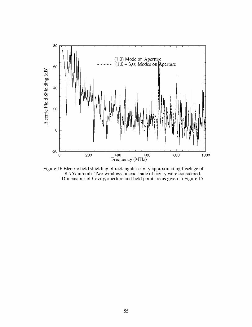
Figures 15-17 shows the electric field shielding when higher order modes on the apertures
were considered. In Figures 15-17, the incident wave was considered to be parallel to the longer
dimensions of the aperture windows. For the frequency range shown in Figures 15-17 it is clear
that single p = 1, q = 0 mode on the aperture is adequate for obtaining convergent results. Fig-
ure 18 shows the electric field shielding of a rectangular cavity with two apertures when the inci-
dent wave was polarized parallel to the shorter dimension of the window. The dimensions of the
53

cavity and aperture used in numerical data shown in Figure 18 were the same as given in Figure
15. Only a single aperture mode was considered in the numerical data shown in Figure 18.
o_,-_
(Do_,-_
(Do_,-_
o_,-_
(D
1°°t
8O
6O
4O
2O
Measured Va
Measured Va
I .... I .... I .... I''
I
ue at 1
|ue at 430 Mt
z
[z
-200 200 400 600 800
Frequency (MHz)
1000
Figure 15 Electric field shielding of rectangular cavity approximating fuselage ofB-757 aircraft. Two windows on each side of cavity were considered.
Cavity size ( 3600 x 400 x 400) cm 3, window size (25 x 35) cm 2, window
locations ( 1800, 200, 0.0) cms and (1800, 200, 400) cms.Field point location (1800, 120, 200) cms.
54
o_,-_
o_,-_
o_,-_
8O
6O
4O
2O
I .... I .... I
(1,0) Mode on Aperture(1,0 + 3,0) Modes on
I
?erture
-200 200 400 600 800
Frequency (MHz)1000
Figure 16 Electric field shielding of rectangular cavity approximating fuselage ofB-757 aircraft. Two windows on each side of cavity were considered.
Dimensions of Cavity, aperture and field point are as given in Figure 15
55

-- ' ' I .... I .... I ....80 - (1,0) Mode on Aperture(1,0 + 3,0)Modes on Aperture-- (1,0 + 3,0 + 5,0)Modes on Aperture
_, 6o
40
2o
0
_ _ _ I _ _ _ _ I _ _ _ _ I _ _ _ _ I _ _ _ _ -
200 400 600 800 1000
Frequency (MHz)
Figure 17 Electric field shielding of rectangular cavity approximating fuselage ofB-757 aircraft. Two windows on each side of cavity were considered.
Dimensions of cavity, aperture and field point are as given in Figure 15
56

8O
6O
4O
2O
-2O
''l .... I
-- (1,0 + 3,0 + 5,0)Modes on Aperture
0 200 400 600 800 1000
Frequency (MHz)
Figure 18 Electric field shielding (for horizontal polarization) of rectangular cavity
approximating fuslelage ofB-757 aircraft. Two windows on each side of
cavity were consideredDimensions of cavity, aperture and field point
are as given in Figure 15
3.4 Convergence Test For Large size Cavities
The numerical estimate of electric field shielding in an electrically large size cavities illu-
minated through large size the apertures depends upon the number of cavity modes as well as
aperture modes considered in the numerical simulation. An adequate number of cavity modes and
aperture modes must be considered to achieve numerical stable results. In this section, depen-
dence of the electric field shielding on number of cavity modes and aperture modes is studied
through numerical examples.
For numerical estimate of electric field shielding, we first consider a rectangular cavity
57

( 5400x 600x 600) cm3,whichapproximatesthefuselageof a Boeing-747.Fornumericalsim-
ulationonly two windows;oneoneachsideof fuselagewere considered.Theaperturedimen-
sionsselectedfor thenumericalsimulationwere( 25x 35)cm2. Thewindowwasassumedto be
locatedwith their centersat (2700,300,0.0)cms and(2700,300, 600)cms. Usingthecomputer
codedevelopedhere,theelectricfield in volts/metercalculatedat (2700,300,300)cms asafunc-
tion of modeindex n is presented in Figure 19. In the numerical simulation it is assumed that
the incident wave is polarized in the y-direction. In Figure 19, stable results are obtained for the
cavity mode index n higher than 200. For Figure 19, only a single mode at the aperture was con-
sidered.
For the cavity and window dimensions as shown in Figure 19, the electric field at the cen-
ter of cavity is calculated and shown in Figure 20 as a function of cavity mode index m. From
Figure 20 it is clear that m > 1200 achieves numerically stable results.
After selecting the cavity mode indices m, n for numerically stable results, the electric
field at the center of the cavity with dimensions as shown in Figure 19 is calculated as a function
of aperture modes and shown in Figure 21. From Figure 21 it may be concluded that for normal
incidence the 4 or 5 aperture modes are sufficient to obtain numerically stable results. Consider-
ation of higher order modes on the aperture improves the accuracy of the numerical calculation
but increases the computational time significantly. For fast computation of electric field shielding,
we consider only single mode at the aperture.
58

5
4
3
2
1
O'
-1
-2
-3
-4
-5
I i
_m
iii
, i i i i i I
Real Part of Ey
Imaginary Part of Ey
50 100 150 200
Figure 19 Electric field amplitude at (2700, 300, 300) cms inside a rectangular cavity
( 5400x600x600 ) cm 3 illuminated_by plane wave at normal incidence throughrectangular windows (25 x 35) cm_as a function of cavity mode index n.
Other parameters: cavity mode index m = 1200, frequency = 2.87510864 GHz.
59

.... I .... I .... I .... I .... I ....
- - • - Real Part of Ey- - • - Imaginary Part of Ey
-1
-2
-3
-4
-5
IllI
LrIf
II
Ii
200 400 600 800 1000 1200
Figure 20 Electric field amplitude at (2700, 300, 300) cms inside a rectangular cavity3
(5400x600x600) cm illuminated by plane wave at normal incidence throughrectangular windows (25 x 35) cm _ as a function of cavity mode index m.
Other parameters: cavity mode index n = 200, frequency = 2.87510864 GHz.
60

5
4
3
2
1
0
-1
-2
-3
-4
-5
.... I .... I .... I .... I .... I .... I .... I .... I ....
I.
-\
-\
\
\
\
\
- - • - - Real Part of Ey- - • - - Imaginary Part of Ey
---0 .... --0- .... 0 .... • .... 0
\ _---- _il- .... • .... -in ....
\ ,JR /
\ /
\\ //
\ j/
"-!/
--i- .... • .... •
Figure 21 Electric field amplitude at (2700, 300, 300) cms inside a rectangular cavity(5400x600x600) cm _ illuminated 12y plane wave at normal incidence throughrectangular windows (25 x 35) cm _ as a function of number of modes on apertures.
Other parameters are cavity mode index n = 200, m = 1200,frequency = 2.8745GHz.
61

4.0 Conclusion
A method suitable for estimation of electric field shielding effectiveness of large but reg-
ular shaped rectangular cavity with multiple rectangular apertures is presented. Assuming appro-
priate electric field distribution on the aperture, fields inside the cavity are determined using
rectangular cavity Green's function. Electromagnetic fields outside the cavity and scattered due
to the aperture are obtained using the free space Green's function. Matching the tangential mag-
netic field across the apertures, the integral equation with aperture fields as unknown variables is
obtained. The integral equation is solved for unknown aperture fields using the Method of
Moments. From the aperture fields the electromagnetic shielding effectiveness of the rectangular
cavity is determined.
Numerical results on electric field shielding of a rectangular enclosure are validated with
data available in the literature. Effects of cavity and aperture modes for large size enclosure are
studied. Approximating a Boeing-757 aircraft cabin by a rectangular cavity and passenger win-
dows by rectangular aperture electromagnetic field penetrations inside the cabin due to external
plane wave at normal incidence are estimated. Electromagnetic field penetrations due to horizon-
tal as well as vertical polarizied incident fields are studied. Though in the present report electro-
magnetic field penetration through two apertures, one on each side of fuselage is estimated, the
computer code can be used to simulate effects of multiple apertures on each side of fuselage.
One advantage of the present method is that the order of matrix equation to be solved in
the present approach is very small compared to the order of matrix equation one encounters in the
Finite Element Method. Another advantage is that the computer storge requirement for the
present approach is negligibly small compared to the Finite Element Method and Finite Differ-
ence Time Domain method. However, because of the use of the cavity Green's function it is very
62

difficult to takeinto accountthecomplexgeometriesandobjectsthatmaybe presentin thepas-
sengercabins. Also, themethoddoesnot takeinto accountthe lossesthatwill bepresentin prac-
tical aircraftcabin.Inspiteof its inadequatenessin handlinglossesin thesystemandcomplex
geometries,thepresentmethodgivesquick andfairly accurateestimatesof electromagnetic
shieldingeffectivenessof rectangularenclosures.
AcknowledgementThe author is grateful to Dr. C. J. Reddy, Hampton University, Hampton, Virginia, for pro-
viding FEM/MoM numerical results shown in Figures 10 and 12.
References
[1] H. A. Mendez, " Shielding theory of enclosures with apertures, "IEEE Trans. on Electromag-
netic Compatibility, Vol. EMC -20, No. 2, pp. 296-305, May 1978.
[2] G. Cerri, R. D. Leo, and V. M. Primiani," Theoretical and experimental evaluation of the elec-
tromagnetic radiation from apertures in shielded enclosures, "IEEE Trans. on Electromag-
netic Compatibility, Vol. EMC -34, No. 4, pp. 423-432, Nov. 1992.
[3] M. E Robinson, et al., "Analytical formulation for the shielding effectiveness of enclosures
with apertures, "IEEE Trans. on Electromagnetic Compatibility, Vol. EMC-40, No. 3, pp.
240-247, August 1998.
[4] M. E Robinson, et al., "Shielding effectiveness of a rectangular enclosure with a rectangular
aperture, "Electronics Letter, Vol. 32, No. 17, pp. 1559-1560, 15th August 1996.
[5] D. A. Hill, et al., "Aperture excitation of electrically large, lossy cavities, "IEEE Trans. on
Electromagnetic Compatibility, Vol. EMC 36, No. 3, pp. 169-178, August 1994.
[6] K. S. Kunz and R. J. Luebbers, "The finite difference time domain methods for electromagnet-
ics, "Orlando, FL, CRC, 1993.
[7] C. J. Reddy et al., "A combined FEM/MoM/GTD technique to analyze elliptically polarized
cavity-backed antenna with finite ground plane, "NASA Technical Paper 3618, Nov. 1996.
63

[8] C. J.ReddyandM. D. Deshpande,"User'sManualfor CBS3DSVersion1.0,"NASA Con-
tractorReport198236,Oct. 1995.
Appendix I
In this appendix we evaluate the integral II_rpqx(X',y')sin cos dx'dy' ina
closed form. Substituting for _rpqx(X', y') the expression for Irpqmnx Can be written as
W,. L,.
2 2
I I sin(Prc(Lr x"]']c°s(qrc(Wr" "_'_" (mrc(x'+xr)" _ {nrc(y'++ .y))_ln/ ? )co_/ _ Y'))e_'dy'\L r \ 2 )) \Wr\ 2
W,. L,.
2 2
thIn above equation x,,, y,, are the coordinates of the center of r
tion expression for Irpqmnx Can be written as
prcL,. [ sin(_(_ + x,.))+ sin ))}. .2 {'mrCLr_[
tprt) - _---7--)
-(nrO/b{ "(nrCWr sin _--b- _-_-"(nrCWr ))}(qr(,]2_(b)2 cos(qrc)sln_--b-_--_-+ y,.)) + -y,. (98)
aperture. Performing the integra-
Appendix II
closed form. Substituting for OPrpqy(X' , y') the expression for Irpqmny Can be written as
W,. L,.
2 2
I I c°s(Prc(L" x'))sin(qrc(W"--"_'_ (mrc(x'+ (nrc(y'+\ L,. \ 2 + )) \W,.\ 2 -r y ))cos_ a x"))sin_ ' -b Y"))dx'dy'
W,. L,.
2 2
thIn above equation x,., y,. are the coordinates of the center of r
tion expression for Irpqmny Can be written as
2 (nrcw,.', [
-t--c-)
in a
aperture. Performing the integra-
+ y,)/}
64

pro 2 mrc 2(99)
Appendix III
The Fourier transforms (p,.pqy and _t,.pq x of _,.pqy and qJ,-pqx, respectively are derived in
this appendix. Using the defination _trpqx(kx, ky) = IIqJ,.pqye jLx jk_Ydxdy, the Fourier trans-
form ltlrpqx can be written as
L,.W,. jLx,. jk_y,. JP2_sin( pro 2L/ JP2_sin(_ +
ltlrpqx -- 4j e " e - e kxL, [pro kxL,. p_____+ __J2 2 2 2
e
qrc kyWr
2 2
Following the same procedure the Fourier transform of _rpqy Can be written as
j k ,. k ]
L,.W,. jLx,. jk_y,. JP2_sin( pro 2L ) JP2_sin(_ + _"/
_rpqy -- 4j e " e + epro kxLr pro kxLr2 2 2+2
_IeJq2_sin (qrc kyW'_ I jq2_sin(_ + kY@) l
The expressions for ltlrpqx and (J)rpqy are obtained from expressions for ltlrpqx and (J)rpqy, respec-
tively by replacing kx, ky by -k x, -ky respectively.
Appendix IVIn this appendix, the expressions for electric field inside the cavity due to magnetic cur-
rent sources present on its walls are given. Using the electric vector potential given in (31) and
expression (23), the electric field components inside the cavity due to the x component of mag-
netic current sources at z = 0 plane are obtained as
65

EllxOx = 0
EllxO R _ 1 eOmeOn (k 2 (nrc)e)sin(mrCX)cos(nrcy)
r 1P, q m, n
sin( kl( C - z) )l rpqmnx
R_llxO 1 eOt,,eOn nrc. (mrcx'_. (nrcy'_
- _ - sin -- sin --E, = E EU,pqEklabsin(ksc ) b t a ) t b )
r 1P, q m, n
COS ( kl( C - z ) )I rpqmnx
Likewise the electric field components due to the x-component of magnetic current sources at
z = c plane are obtained as
EllXcx = 0
e _ 1 eOt,,eOn r 2 {rtT(k2"_. {'mrcx'_ (nrcy'_
_ _ tk- sin cos--:--_"_ -ot.-c)) t-a--J t _,)_ =- E EB,,,,Eklabsin(k c)r lP, q m,n
sin( klz)I ,.pqmnx
R "__Ilxc 1 e o,,eon nrCsin(mrCX)sin(n_Y 3#__ = Z ZB,pqZkzabsin(ksc) b t. a ) t. 0 )
r 1P, q rn, n
COS ( k lZ )I rpqmnx
66

REPORT DOCUMENTATION PAGE Form ApprovedOMBNO.0704-0188
Public reporting burden for this collection of information is estimated to average 1 hour per response, including the time for reviewing instructions, searching existing datasources, gathering and maintaining the data needed, and completing and reviewing the collection of information. Send comments regarding this burden estimate or any otheraspect of this collection of information, including suggestions for reducing this burden, to Washington Headquarters Services, Directorate for Information Operations and
Reports, 1215 Jefferson Davis Highway, Suite 1204, Arlington, VA 22202-4302, and to the Office of Management and Budget, Paperwork Reduction Project (0704-0188),Washington, DC 20503.
1. AGENCY USE ONLY (Leave blank) 2. REPORT DATE 3. REPORT TYPE AND DATES COVERED
June 2000 Contractor Report
4. TITLE AND SUBTITLE
Electromagnetic Field Penetration Studies
6. AUTHOR(S)
M. D. Deshpande
7. PERFORMING ORGANIZATION NAME(S) AND ADDRESS(ES)
NYMA, Inc.
NASA Langley Research CenterHampton, VA 23681-2199
9. SPONSORING/MONITORING AGENCY NAME(S) AND ADDRESS(ES)
National Aeronautics and Space AdministrationLangley Research Center
Hampton, VA 23681-2199
5. FUNDING NUMBERS
C NAS 1-96013
WU 522-31-21-04
8. PERFORMING ORGANIZATION
REPORT NUMBER
10. SPONSORING/MONITORING
AGENCY REPORT NUMBER
NASA/CR-2000-210297
11. SUPPLEMENTARY NOTES
M. D. Deshpande, FDC/NYMA Inc., Hampton, VALangley Technical Monitor: Fred B. Beck
12a. DISTRIBUTION/AVAILABILITY STATEMENT
Unclassified-Unlimited
Subject Category 32 Distribution: NonstandardAvailability: NASA CASI (301) 621-0390
12b. DISTRIBUTION CODE
13. ABSTRACT (Maximum 200 words)
A numerical method is presented to determine electromagnetic shielding effectiveness of rectangular enclosurewith apertures on its wall used for input and output connections, control panels, visual-access windows,
ventilation panels, etc. Expressing EM fields in terms of cavity Green's function inside the enclosure and thefree space Green's function outside the enclosure, integral equations with aperture tangential electri fields as
unknown variables are obtained by enforcing the continuity of tangential electric and magnetic fields across theapertures. Using the Method of Moments, the integral equations are solved for unknown aperture fields. From
these aperture fields, the EM field inside a rectangular enclosure due to external electromagnetic sources aredetermined. Numerical results on electric field shielding of a rectangular cavity with a thin rectangular slot
obtained using the present method are compared with the results obtained using simple transmission linetechnique for code validation. The present technique is applied to determine field penetration inside a Boeing-
757 by approximating its passenger cabin as a rectangular cavity filled with a homogeneous medium and its
passenger windows by rectangular apertures. Preliminary results for, two windows, one on each side of fuselagewere considered. Numerical results for Boeing -757 at frequencies 26 MHz, 171-175 MHz, and 428-432 MHz
are presented.
14. SUBJECT TERMS
EM Penetration, EM Shielding, Aperture Coupling, EM Susceptibility
17. SECURITY CLASSIFICATION
OF REPORT
Unclassified
18. SECURITY CLASSIFICATION
OF THIS PAGE
Unclassified
19. SECURITY CLASSIFICATION
OF ABSTRACT
Unclassified
15. NUMBER OF PAGES
71
16. PRICE CODE
A04
20. LIMITATION
OF ABSTRACT
UL
NSN 7540-01-280-5500 Standard Form 298 (Rev. 2-89)
Prescribed by ANSI Std. Z-39-18298-102


