
Energy Efficient 3 Phase LV Induction Motors
Catalogue 2010
• Inverter Duty Motors• Crane Duty Motors• Brake Motors

Type of Motors Page
Inverter Duty Motors 3-4
Crane Duty Motor 5-9
Brake Duty Motor 10-14
Contents
About usHavells India Ltd, a US$1bn plus company, and one the largest & India’s fastest growing
electrical and power distribution equipment companies, manufacturing products ranging from Building Circuit Protection, Industrial & Domestic Switchgear, Cables, Fans, CFL Lamps, Luminaires for Domestic, Commercial & Industrial application and Modular Switches.
Havells owns some of the prestigious global brands like Crabtree, Sylvania, Concord, Lumiance, Claude, Linolite, SLI Lighting & Zenith.
With 91 branches / representative offices and over 8000 professionals spread over 50 countries across the globe, the group has achieved rapid success in the past few years. Its 15 state of the art manufacturing plants spread over India, Europe, Latin America & Africa churns out globally acclaimed products.
To add to the existing state-of-the-art manufacturing plants, Havells has now started a world class Motor Plant at Neemrana (Rajasthan). It is one of the largest LV Motor Plant in Asia spread over 42 acres and will manufacture energy efficient motors ranging from 0.12HP to 300HP.
The plant has a capacity of manufacturing over 20000 motors per month. The state-of-the art plant and machinery has been imported from AEG Spain.
The Manufacturing Strengths of the Plant are :
• Inhousemanufacturingofcompleterangeofmotorsfrom56to315frame
• Automaticwindinglinesfrom56to250frame
• Automaticimpregnationplant
• Ultra-violetimpregnationplant
• Fullyautomatedtemperaturecontrolledpaintstations
• Typetestpanelwithmultipletestbedwithpoweranalysers
• MechanicalTestLab
Havells is committed to manufacturing excellence and providing world class quality products at affordable prices. Havells offers a complete solution which is not only safe and reliable but also saves energy. We continue the same tradition with our motors.
(2)
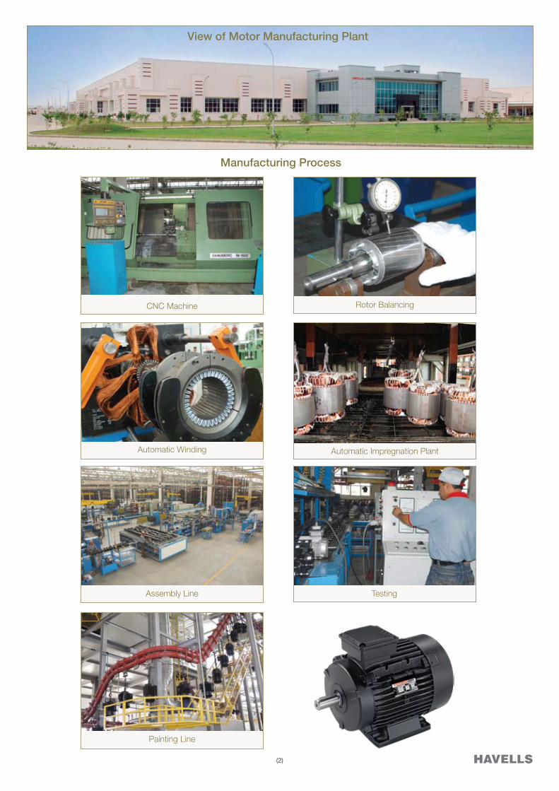
Automatic Winding Automatic Impregnation Plant
CNC Machine
Assembly Line
Painting Line
Testing
Manufacturing Process
View of Motor Manufacturing Plant
Rotor Balancing

(3)
Features
Voltage : 3 Ph., 415 V
Other voltage as per
requirement
Frequency : 50 Hz
Other frequency as per requirement
Ambient : 50 Deg. C
Ins. Class : F ( Temp. rise Class B)
Range : 0.37 kW to 55 kW
Pole : 2,4,6and8Pole
Frame : 80 to 250
Frequency Range : 20 to 75 Hz
Mounting : B3, B5, B14 and combination
Cooling : IC416
While selecting the motor, maximum allowed speed of the motor is also to be considered. For 2 pole motors, the maximum allowedspeed is4000rpmandfor4polemotors, it is3600rpm.
When the nominal supply voltage of the converter is more than 500 V, it is recommended to use du/dt filters which reduce voltage stresses in the winding by reducing the rate of change of phase and main voltages.
The use of converters with motors also demands extra requirements in terms of cabling and grounding of the drive system. Although asymmetrical cables can be used for the cabling but it is recommended to use shielded symmetrical cables along with EMC glands.
Torque Characteristics of motor driven with frequency converter
Havells manufactures squirrel cage inverter duty motors which are specially designed for operations requiring wide speed variation through variable speed drives. These motors are generally used when the motor is running for longer duration at speeds below 70% of rated name plate speed.
Inverter duty motors operate at constant torque upto rated design frequency when connected with variable frequency drives.
The motors are fitted with separate cooling arrangement which ensures that the motors perform successfully at lower speeds without over-heating of the motor. This also ensures that the loading capacity of the motor is not reduced in this range.
All external cooling fans are rated at 3000 rpm which provide excellent cooling to the motors even at lower speed of operation.
Enclosure : Totally Enclosed Separately Cooled
Protection : IP 55
Standards : IS: 325, IS: 1231, IS: 2223
IS: 4722
Deration Factor for Higher Ambient
Ambient temp. Deration Factor
55 Deg. C 0.94
60Deg.C 0.88
Encoder Mounting
The motors are provided with encoder mounting arrangement as a standard feature which is required by customers for motor control.
The loadability curve of the motor is as shown below:
Inverter Duty Motors(With Forced Cooling)

(4)
Rating Chart
2 POLE 4 POLE 6 POLE 8 POLE
FRAME KW H.P FRAME KW H.P FRAME KW H.P FRAME KW H.P
MH 80Z AA 2 0.75 1 MH 80Z AA 4 0.55 0.75 MH80ZAA6 0.37 0.5 MH 80Z AA 8 0.25 0.33
MH 80Z BA 2 1.1 1.5 MH 80Z BA 4 0.75 1 MH80ZBA6 0.55 0.75 MH 90S AA 8 0.37 0.5
MH 90S AA 2 1.5 2 MH 90S AA 4 1.1 1.5 MH90SAA6 0.75 1 MH 90L BA 8 0.55 0.75
MH 90S BA 2 1.8 2.5 MH 90L BA 4 1.5 2 MH90LBA6 1.1 1.5 MH 100L AA 8 0.75 1
MH 90L CA 2 2.2 3 MH 100L AA 4 2.2 3 MH100LAA6 1.5 2 MH 100L BA 8 1.1 1.5
MH 100L AA 2 3 4 MH 112M AA 4 3.7 5 MH112MAA6 2.2 3 MH 112M AA 8 1.5 2
MH 100L BA 2 3.7 5 MH 132S ZA 4 5.5 7.5 MH132SYA6 3.7 5 MH 132S ZA 8 2.2 3
MH 112M AA 2 3.7 5 MH 132M ZA 4 7.5 10 MH132MZA6 5.5 7.5 MH160MYA8 3.7 5
MH 132S YA 2 5.5 7.5 MH160MYA4 9.3 12.5 MH160MZA6 7.5 10 MH160MZA8 5.5 7.5
MH 132 S ZA 2 7.5 10 MH160MXA4 11 15 MH160LYA6 9.3 12.5 MH160LZA8 7.5 10
MH160MTA2 9.3 12.5 MH160LXA4 15 20 MH160LZA6 11 15 MH 180L YG 8 9.3 12.5
MH160MVA2 11 15 MH180MXG4 18.5 25 MH180LZG6 15 20 MH 180L ZG 8 11 15
MH160MXA2 15 20 MH180LXG4 22 30 MH200LPG6 18.5 25 MH 200L RG 8 15 20
MH160LXA2 18.5 25 MH 200L NG 4 30 40 MH200LRG6 22 30 MH 225S P 8 18.5 25
MH180MXG2 22 30 MH 225S N 4 37 40 MH225MP6 30 40 MH 225M P 8 22 30
MH 200L LG 2 30 40 MH 225M N 4 45 60 MH250MP6 37 50 MH 250M P 8 30 40
MH 200L NG 2 37 50 MH 250M N 4 55 75
Frame Pole General DimensionsD E F L GA H A B C K HD K1
80 2-8 19j6 40 6 366 21.5 80 125 100 50 10 219 14
90S 2-8 24j6 50 8 550.5 27 90 140 100 56 10 238 15
90L 2-8 24j6 50 8 550.5 27 90 140 125 56 10 238 15
100L 2-8 28j6 60 8 589.5 31 100 160 140 63 11 255 17
112M 2-8 28j6 60 8 514 31 112 190 140 70 12.5 283 19
132S 2-8 38k6 80 10 570 41 132 216 140 89 12 327 20
132M 2-8 38k6 80 10 629.5 41 132 216 178 89 12 327 20
160M 2-8 42k6 110 12 716.5 45 160 254 210 108 14 400.5 18
160L 2-8 42k6 110 12 780.5 45 160 254 254 108 14 400.5 18
180M 2-8 48k6 110 14 797 51.5 180 279 241 121 14 470 18
180L 2-8 48k6 110 14 797 51.5 180 279 279 121 14 470 18
200L 2-8 55m6 110 16 909.5 59 200 318 305 133 18 541 18
225S 2 55m6 110 16 951.5 59 225 356 286 149 18.5 585 19
4 60m6 140 18 981.5 64 225 356 286 149 18.5 585 19
225M 2 55m6 110 16 951.5 59 225 356 311 149 18.5 585 19
4 60m6 140 18 981.5 64 225 356 286 149 18.5 585 19
250M 2 60m6 140 18 1055 64 250 406 349 168 22 640 28
4 65m6 140 18 1055 69 250 406 349 168 22 640 28
Note: For other dimensions refer to Latest Havells Standard Motor Catalogue
Note:- For higher ratings, please refer our nearest marketing office

(5)
Havells India Ltd. Crane Duty Motors have been suitably designed for arduous applications for short and intermittent duties involving starts, stops and reversals.
These motors are used on applications like cranes, lifts, material handling, weirs and sluices and auxiliary motors in rolling mills.
Crane Duty motors are designed to have high starting torque with low starting currents. These characteristics ensure that the motors have high acceleration torques that are required in frequent start/ stop applications.
Product Range
Frame : 71-160
kW/Hp : 0.37 – 15 / 0.5 - 20
Pole : 4-8 Pole
Mounting : Foot, Flange, Face and combination
CE Marking
All motors have CE Marking.
Operating Conditions
The standard operating conditions for the crane duty motors are:
Voltage : 415 ± 10% Volts
Frequency : 50 ± 5 % Hz
Combined : ± 10 %
Ambient Temperature : 450 C
Altitude : Upto 1000 m above mean sea level
In case any operating conditions are different than above, please contact nearest branch office of Havells India Ltd.
Standards
The motors conform to the following standards
IS: 325 Three Phase Induction Motors- Specification
IS: 1231 Dimensions of Three Phase Foot Mounted Induction Motors
IS: 2223 Dimensions of Flange Mounted Induction Motors
IS: 4722 Rotating Electrical Machines- Specification
IS:4691 Degree of Protection For Rotating ElectricalMachines
IS:6362 Designation of Methods of Cooling of RotatingElectrical Machines
Electrical Design
Winding
All crane duty motors are manufactured using dual coat class F copper wire (with temperature withstand up to 1550C) as standard.
Insulation
The motors are having class F insulation with temperature rise limited to Class B. The motors are impregnated in a computerized impregnation plant that ensures high quality of impregnation with high varnish retention.
Deration for Higher Ambient & Altitude
For selection of motors for higher ambient and altitude, the rated kW should be reduced by the following factors for the frame selection.
Ambient 450C 500C 550C 600C
Factor 100% 95% 90% 80%
Altitude 1000m 1500m 2000m 2500m 3000m
Factor 100% 95% 92% 88% 84%
Intermittent Duty Application
The motors are designed for intermittent duty operations and different starts/stops per hour as shown in the rating charts.
The frame selections are based considering load GD2 values referred to motor shaft are less than or equal to motor GD2 values. Various intermittent duty types are explained below.
Short Time Duty - S2 Duty
The motor operates at constant load for a given duration which is less than that required to reach thermal equilibrium and is followed by a rest or de-energized period such that the motor cools down to close to ambient temperature.
Therecommendedvaluesfortheshorttimedutyare10,30,60and 90 minutes.
N = Operation at constant loadØmax = Maximum temperature attained
during the duty cycle
Crane Duty Motors

(6)
Intermittent Periodic Duty with Starting- S3 Duty
The operation cycle consists of operation at constant load followed by a rest and de-energized period. The duty cycle is such that thermal equilibrium is not reached during one periodic cycle.
Intermittent Periodic Duty with Starting- S4 Duty
In this duty cycle, each cycle consist of a period of starting, a period of operation at constant load followed by a rest and de-energized period. The duration of one cycle is so short that thermal equilibrium is not reached during one duty cycle.
N = Operation at constant loadR = At rest and de-energizedØmax = Maximum temperature attained during
the duty cycle
Cycle duration factor = 100%NN + R
D = StartingN = Operation at constant loadR = At rest and de-energizedØmax = Maximum temperature attained during
the duty cycle
Cycle duration factor = 100%D + ND + N + R
Mechanical Design
Construction
Crane Duty Motors are available in Aluminum/ Cast Iron frames as per table below:
Frame Body End-Shield
71-90 Aluminum Aluminum
100-132 Aluminum Cast Iron
100-160 Cast Iron Cast Iron
Frames 80 & 90 shall also be available in Cast Iron on request.
For higher frames, kindly refer to nearest branch office.
Enclosure
All motors are Totally Enclosed Fan Cooled (TEFC) as per IS 4691andaresuitabletooperate inbothoutdoorand indoorapplications.
Cooling
The motors are designed with IC0141 method of cooling as per IS6362whichprovidesexcellentheatdissipationofthemotorsand ensures longer life of the motor.
Frame Bearing DE/ NDE
71 6203-2Z/6203-2Z
80 6204-2ZC3/6204-2ZC3
90 6205-2ZC3/6205-2ZC3
100 6206-2ZC3/6206-2ZC3
112 6306-2ZC3/6306-2ZC3
132 6208-2ZC3/6208-2ZC3
160 6309-2ZC3/6309-2ZC3
Terminal Box
Terminal box is provided on top as a standard.
The details of Terminal Box and maximum cable size are shown in the table.
Information required at the time of enquiry
The following information should be provided at the time of enquiry.
1. Motor kW and Pole
2. Application
3. Supply voltage and frequency with variation
4. Ambient Temperature
5. Duty Type, CDF and number of starts/ stops per hour
6. Mountingarrangement
7. Load GD2 referred to motor shaft (If more than Motor GD2)
8. Degree of protection
9. Shaft extension, If other than standard
10. Any other relevant information
Frame Max. Cable
Size
No. of
Termi-
nals
Terminal
Stud
Size
Cable Entry
Nos. Size
71 4C x 4 mm2 6 M4 2 M16M20
80 4C x 4 mm2 6 M4 2 M20 M25
90 4C x 10 mm2 6 M5 2 M20 M25
100 4C x 10 mm2 6 M5 2 M20 M25
112 4C x 10 mm2 6 M5 2 M20 M25
132 4C x 10 mm2 6 M5 2 M32 M32
160 3C x 50 mm2 6 M6 2 M40 M40
Degree of Protection
Degree of protection for machines are designated in accordance withIS4691byletterIPfollowedbytwocharacteristicnumeralscorresponding to protection from dust and water. All motors are provided with IP55 degree of protection as a standard and are suitable for operation in dusty and humid environment conditions.
Bearing Details
All motors are fitted with deep groove ball bearings with C3 clearance and greased for life ensuring longer trouble free operation. The details of bearings used are given in the table.

(7)
Frame 60Starts/hour 90 Starts / hour Motor GD2
kGm2
x10-325% CDF 40% CDF 60%CDF 25% CDF 40% CDF 60%CDF
kW kW kW kW kW kW
71ZCA4 0.55 0.55 0.55 0.55 0.55 0.55 3.92
80ZAA4 0.55 0.55 0.55 0.55 0.55 0.55 6.32
80ZBA4 0.75 0.75 0.75 0.75 0.75 0.75 8.0
80ZCA4 1.1 1.1 1.1 1.1 1.1 1.1 9.64
90SAA4 1.1 1.1 1.1 1.1 1.1 1.1 10.0
90LBA4 1.5 1.5 1.5 1.5 1.5 1.5 12.52
90LDA4 2.2 2.2 2.2 2.2 2.2 2.2 16.2
100LAA4 2.2 2.2 2.2 2.2 2.2 2.2 18.4
100LBA4 3.0 3.0 3.0 3.0 3.0 3.0 22.32
100LCA4 3.7 3.7 3.3 3.7 3.7 3.3 24.2
112MAA4 3.7 3.7 3.7 3.7 3.7 3.7 48.8
112MBA4 5.5 5.5 5.0 5.5 5.5 5.0 60.8
132SZA4 5.5 5.5 5.5 5.5 5.5 5.5 88.0
132MZA4 7.5 7.5 7.5 7.5 7.5 7.5 120
132MRA4 9.3 9.3 9.3 9.3 9.3 8.5 148.8
160MXA4 11 11 11 11 11 9.9 324.8
160LXA4 15 15 15 15 15 15 422.8
4 Pole (Speed 1500 RPM)
Selection ChartCrane Duty Motors
(S2 / S3 / S4 Duty)
Frame 150 Starts / hour 300 Starts / hour Motor GD2
kGm2
x10-325% CDF 40% CDF 60%CDF 25% CDF 40% CDF 60%CDF
kW kW kW kW kW kW
71ZCA4 0.55 0.55 0.5 0.5 0.45 0.4 3.92
80ZAA4 0.55 0.55 0.55 0.55 0.5 0.45 6.32
80ZBA4 0.75 0.75 0.75 0.67 0.6 0.6 8.0
80ZCA4 1.1 1.1 1.0 1.0 1.0 0.8 9.64
90SAA4 1.1 1.1 1.1 1.1 1.1 1.0 10.0
90LBA4 1.5 1.5 1.5 1.5 1.5 1.3 12.52
90LDA4 2.2 2.2 2.2 2.2 2.0 2.0 16.2
100LAA4 2.2 2.2 2.2 2.2 2.2 2.0 18.4
100LBA4 3.0 3.0 3.0 2.8 2.8 2.5 22.32
100LCA4 3.7 3.3 3.0 3.0 3.0 2.5 24.2
112MAA4 3.7 3.7 3.7 3.7 3.3 3.0 48.8
112MBA4 5.5 5.5 4.5 4.5 4.0 3.5 60.8
132SZA4 5.5 5.5 5.5 5.5 5.0 4.0 88.0
132MZA4 7.5 7.5 7.5 7.5 7.0 6 120
132MRA4 9.3 8.5 8.0 7.7 7.2 6.8 148.8
160MXA4 11 11 9.3 8.0 7.5 7.0 324.8
160LXA4 15 15 13.5 13.5 11 9.3 422.8
4 Pole (Speed 1500 RPM)
Note: 1. Load GD2 value should not be more than motor GD2 value. 2. All motors suitable for an Ambient Temperature of 45 deg. C.

(8)
Crane Duty Motors(S2 / S3 / S4 Duty)
Frame 60Starts/hour 90 Starts / hour Motor GD2
kGm2
x10-325% CDF 40% CDF 60%CDF 25% CDF 40% CDF 60%CDF
kW kW kW kW kW kW
80ZAA6 0.37 0.37 0.37 0.37 0.37 0.37 7.88
80ZBA6 0.55 0.55 0.55 0.55 0.55 0.55 9.88
90SAA6 0.75 0.75 0.75 0.75 0.75 0.75 12.72
90LBA6 1.1 1.1 1.1 1.1 1.1 1.1 19.12
100LAA6 1.5 1.5 1.5 1.5 1.5 1.5 26.92
100LBA6 1.8 1.8 1.8 1.8 1.8 1.8 37.72
112MAA6 2.2 2.2 2.2 2.2 2.2 2.2 56.72
112MBA6 3.0 3.0 3.0 3.0 3.0 2.7 74.8
132SZA6 3.0 3.0 3.0 3.0 3.0 3.0 94.0
132MYA6 3.7 3.7 3.7 3.7 3.7 3.7 118.0
132MZA6 5.5 5.5 5.5 5.5 5.5 5.5 149.2
132MTA6 7.5 7.5 7.0 7.5 7.0 6.5 216.4
160MZA6 7.5 7.5 7.0 7.5 7.0 6.3 324.8
160LYA6 9.3 9.3 9.3 9.3 9.3 9.3 422.8
160LZA6 11 11 11 11 11 11 422.8
6Pole(Speed1000RPM)
Selection Chart
Frame 150 Starts / hour 300 Starts / hour Motor GD2
kGm2
x10-325% CDF 40% CDF 60%CDF 25% CDF 40% CDF 60%CDF
kW kW kW kW kW kW
80ZAA6 0.37 0.37 0.33 0.33 0.33 0.3 7.88
80ZBA6 0.55 0.55 0.5 0.5 0.5 0.45 9.88
90SAA6 0.75 0.75 0.7 0.7 0.7 0.65 12.72
90LBA6 1.1 1.1 0.9 0.9 0.9 0.8 19.12
100LAA6 1.5 1.5 1.3 1.3 1.1 1.1 26.92
100LBA6 1.8 1.8 1.6 1.8 1.5 1.3 37.72
112MAA6 2.2 2.2 2.0 2.0 2.0 1.8 56.72
112MBA6 3.0 3.0 2.7 2.7 2.2 2.0 74.8
132SZA6 3.0 3.0 2.7 2.7 2.7 2.2 94.0
132MYA6 3.7 3.7 3.3 3.3 3.3 3.0 118.0
132MZA6 5.5 5.5 5.0 5.0 5.0 4.5 149.2
132MTA6 7.5 7.0 6.3 6.5 6 5.5 216.4
160MZA6 5.8 5.3 5.0 - - - 324.8
160LYA6 9.3 9.3 9.3 9.3 8.2 7.8 422.8
160LZA6 11 11 9.8 9.8 8.5 8.0 422.8
6Pole(Speed1000RPM)
Note: 1. Load GD2 value should not be more than motor GD2 value. 2. All motors suitable for an Ambient Temperature of 45 deg. C.

(9)
Frame 150 Starts / hour 300 Starts / hour Motor GD2
kGm2
x10-325% CDF 40% CDF 60%CDF 25% CDF 40% CDF 60%CDF
kW kW kW kW kW kW
90SAA8 0.37 0.37 0.37 0.37 0.37 0.33 12.72
90LBA8 0.55 0.55 0.50 0.55 0.50 0.45 19.12
100LAA8 0.75 0.75 0.66 0.68 0.66 0.58 26.88
100LBA8 1.1 1.1 1.0 1.0 0.8 0.7 63.72
112MAA8 1.5 1.5 1.2 1.5 1.2 1.0 66.8
132SZA8 2.2 2.2 2.0 2.0 1.8 1.5 118.0
132MZA8 3 3 2.6 2.8 2.2 1.8 150.8
160MYA8 3.3 3.3 3.0 3.0 2.5 2.0 358.0
160MZA8 5.0 5.0 4.5 4.0 3.5 3.0 478.0
160LZA8 7.5 7.0 6.5 6.0 5.5 5.0 600.8
8 Pole (Speed 750 RPM)
Frame 60Starts/hour 90 Starts / hour Motor GD2
kGm2
x10-325% CDF 40% CDF 60%CDF 25% CDF 40% CDF 60%CDF
kW kW kW kW kW kW
90SAA8 0.37 0.37 0.37 0.37 0.37 0.37 12.72
90LBA8 0.55 0.55 0.55 0.55 0.55 0.55 19.12
100LAA8 0.75 0.75 0.75 0.75 0.75 0.68 26.88
100LBA8 1.1 1.1 1.1 1.1 1.1 1.0 63.72
112MAA8 1.5 1.5 1.5 1.5 1.5 1.2 66.8
132SZA8 2.2 2.2 2.2 2.2 2.2 2.2 118.0
132MZA8 3.0 3.0 3.0 3.0 3.0 3.0 150.8
160MYA8 3.7 3.7 3.7 3.7 3.7 3.3 358.0
160MZA8 5.5 5.5 5.5 5.5 5.5 5.0 478.0
160LZA8 7.5 7.5 7.5 7.5 7.5 7.0 600.8
8 Pole (Speed 750 RPM)
Crane Duty Motors(S2 / S3 / S4 Duty)
Selection Chart
Note: 1. Load GD2 value should not be more than motor GD2 value. 2. All motors suitable for an Ambient Temperature of 45 deg. C.
(10)
Bearing Details
• Therectifierismountedinsidethemainterminalboxsonoseparate terminal box required.
• Specialbrakelinerisusedwhichensures,thebrakingtorquevalue remains quite stable through out the use.
General guidelines for selection of suitable brake model:The brakes are rated by torque & selection of suitable model can be made by calculating the required torque, rating or the brake & then matching it with static torque. Torque (Nm) = 9550 x (KW/RPM) x Safety Factor (SF) where KW-Kilowatts of motor,RPM-Speed of motor,SF-Safety Factor
ApplicationsBrake Motors are used for numerous applications. A few of them are listed below: • Textilemachinery• MachineTools• PrintingMachine• CranesandHoists• MaterialHandlingEquipments• LeatherProcessingMachines• CableReelingDrums• RollingMills• Elevators•Conveyers,etc.
Frame SizeBearing Sizes (C3 Clearance)
DE NDE
63 6202-2Z 6202-2Z
71 6203-2Z 6203-2Z
80 6204-2ZC3 6204-2ZC3
90S, 90L 6205-2ZC3 6205-2ZC3
100L 6206-2ZC3 6206-2ZC3
112M 6306-2ZC3 6306-2ZC3
132S, 132M 6208-2ZC3 6208-2ZC3
160M,160L 6309-2ZC3 6309-2ZC3
Terms to be incorporated while placing an enquiry:• Applicationdetail• Motorpower&speed• Brakesize/requiredbrakingtorque• Mounting• No.ofstart/stopsperhour• Dutycycle
DC Brake Motors:Voltage : 415V +/-10%Frequency : 50Hz +/-5%Combined Variation : +/-10%Ambient Temp. : 50ºCDuty : S1Mounting : B3, B5, B14 & B35Ins. Class : FTemp. Rise : BProtection : IP55
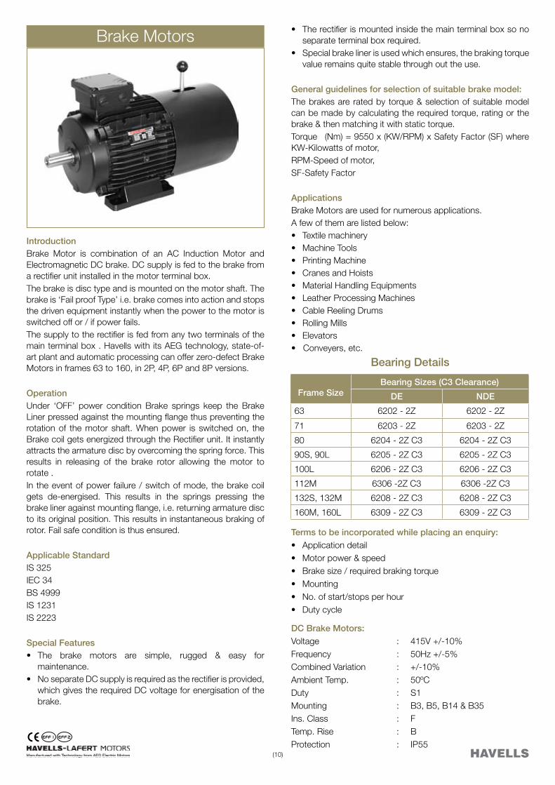
Brake Motors
IntroductionBrake Motor is combination of an AC Induction Motor and Electromagnetic DC brake. DC supply is fed to the brake from a rectifier unit installed in the motor terminal box. The brake is disc type and is mounted on the motor shaft. The brake is ‘Fail proof Type’ i.e. brake comes into action and stops the driven equipment instantly when the power to the motor is switched off or / if power fails. The supply to the rectifier is fed from any two terminals of the main terminal box . Havells with its AEG technology, state-of-art plant and automatic processing can offer zero-defect Brake Motorsinframes63to160,in2P,4P,6Pand8Pversions.
OperationUnder ‘OFF’ power condition Brake springs keep the Brake Liner pressed against the mounting flange thus preventing the rotation of the motor shaft. When power is switched on, the Brake coil gets energized through the Rectifier unit. It instantly attracts the armature disc by overcoming the spring force. This results in releasing of the brake rotor allowing the motor to rotate . In the event of power failure / switch of mode, the brake coil gets de-energised. This results in the springs pressing the brake liner against mounting flange, i.e. returning armature disc to its original position. This results in instantaneous braking of rotor. Fail safe condition is thus ensured.
Applicable Standard IS 325IEC 34BS 4999IS 1231IS 2223
Special Features• The brake motors are simple, rugged & easy for
maintenance. • NoseparateDCsupplyisrequiredastherectifierisprovided,
which gives the required DC voltage for energisation of the brake.

(11)
Performance Table - For Brake PartSelection Chart
KW HP Type Rated Torque Brake Safety KW HP Type Rated Torque Brake Safety
Speed Mn Torque Factor Speed Mn Torque Factor
RPM Nm Nm SF RPM Nm Nm SF
0.12 0.16 MHBY63ZAA4 1350 0.85 5 5.9 2.2 3 MHBY90LCA2 2860 7.35 16 2.2
MHBY71ZAA8 670 1.71 5 2.9 MHBY100LAA4 1435 14.64 35 2.4
0.18 0.25 MHBY63ZAA2 2790 0.62 5 8.1 MHBY112MAA6 940 22.35 60 2.7
MHBY63ZBA4 1330 1.29 5 3.9 MHBY132SZA8 710 29.59 60 2
MHBY71ZAA6 850 2.02 5 2.5 3 4 MHBY100LAA2 2860 10.02 35 3.5
MHBY80ZAA8 680 2.53 10 4 MHBY100LBA4 1425 20.11 60 3
0.25 0.33 MHBY63ZBA2 2790 0.86 5 5.8 MHBY132SZA6 950 30.16 80 2.7
MHBY71ZAA4 1340 1.78 5 2.8 MHBY132MZA8 710 40.35 80 2
MHBY71ZBA6 870 2.74 5 1.8 3.7 5 MHBY100LCA2 2865 12.33 35 2.8
MHBY80ZAA8 680 3.51 10 2.8 MHBY112MAA4 1430 24.71 60 2.4
0.37 0.5 MHBY71ZAA2 2820 1.25 5 4 MHBY132SYA6 950 37.19 80 2.2
MHBY71ZBA4 1370 2.58 5 1.9 MHBY160MYA8 700 50.48 150 3
MHBY80ZAA6 910 3.88 10 2.6 5.5 7.5 MHBY132SYA2 2890 18.17 60 3.3
MHBY90SAA8 680 5.2 16 3.1 MHBY132SZA4 1430 36.73 80 2.2
0.55 0.75 MHBY71ZBA2 2830 1.86 10 5.4 MHBY132MZA6 950 55.29 150 2.7
MHBY80ZAA4 1400 3.75 10 2.7 MHBY160MZA8 720 72.95 150 2.1
MHBY80ZBA6 910 5.77 10 1.7 7.5 10 MHBY132SZA2 2880 24.87 60 2.4
MHBY90LBA8 680 7.72 16 2.1 MHBY132MZA4 1440 49.74 150 3
0.75 1 MHBY80ZAA2 2840 2.52 10 4 MHBY160MZA6 970 73.84 150 2
MHBY80ZBA4 1410 5.08 10 2 MHBY160LZA8 710 100.88 260 2.6
MHBY90SAA6 910 7.87 16 2 9.3 12.5 MHBY132MRA2 2880 30.84 80 2.6
MHBY100LAA8 690 10.38 35 3.4 MHBY160MYA4 1460 60.83 150 2.5
1.1 1.5 MHBY80ZBA2 2810 3.74 10 2.7 MHBY160LYA6 960 92.52 260 2.8
MHBY90SAA4 1400 7.5 16 2.1 11 15 MHBY160MVA2 2940 35.73 80 2.2
MHBY90LBA6 908 11.57 35 3 MHBY160MXA4 1460 71.95 150 2.1
MHBY100LBA8 690 15.22 35 2.3 MHBY160LZA6 960 109.43 260 2.4
1.5 2 MHBY90SAA2 2830 5.06 16 3.2 15 20 MHBY160MXA2 2940 48.72 150 3.1
MHBY90LBA4 1400 10.23 35 3.4 MHBY160LXA4 1460 98.12 260 2.6
MHBY100LAA6 930 15.4 35 2.3 18.5 25 MHBY160LXA2 2950 59.89 150 2.5
MHBY112MAA8 696 20.58 60 2.9
Break Coil Connection Diagram:The Motor must never be switched ON unless the brake is energized and the brake should never be De-energised when the motor is ON. The interlocking of two contactors is Absolutely Necessary.
Note:
1. Other higher braking torque values can be given for special applications.
2. For performance details of motor part, please refer latest standard motor catalogue.

(12)
Frame D/DA E/EA
AD (2)
AL AF F/FA h10
GD L LC GA/GC
DB (3)
AC
63 11 j6 23 96.5 66 92 4 4 290 310 12.5 M4 123
71 14 j6 30 111 69 92 5 5 331 358 16 M5 139
80 19 j6 40 139 79 110 6 6 377 419 21.5 M6 155.6
90S 24 j6 50 148 84.5 110 8 7 421 472 27 M8 176.6
90L 24 j6 50 148 84.5 110 8 7 421 472 27 M8 176.6
100L 28 j6 60 155 91 110 8 7 484 546 31 M10 192
112M 28 j6 60 171 91.5 110 8 7 512 575 31 M10 221
132S 38 k6 80 195 100 133 10 8 567 642 41 M12 248
132M 38 k6 80 195 120 133 10 8 622 698 41 M12 248
132M 38 k6 80 195 120 133 10 8 640 733 41 M12 248
160M 42 k6 110 240.5 146 150 12 8 750 853 45 M16 317
160L 42 k6 110 240.5 168 150 12 8 810 913 45 M16 317
H A B C K(1) AB BB HD (2)
HC HA K1 BA AA
63 100 80 40 7 119 100 159.5 119.5 8 11 29 30
71 112 90 45 8 135 109 182 142 8 11 29 31
80 125 100 50 10 153 125 219 162 9.5 14 28.5 35
90 140 100 56 10 170 150 238 181 11 15 28/53 37
90 140 125 56 10 170 150 238 181 11 15 28/53 37
100 160 140 63 11 192 166 255 198 12 17 38 44
112 190 140 70 12.5 220 175 283 226 15 19 46 48.5
132 216 140 89 12 256 180 327 261 17 20 45 59
132 216 178 89 12 256 218 327 261 17 20 45 59
132 216 178 89 12 256 218 327 261 17 20 45 59
160 254 210 108 14 320 270 400.5 317 23 18 65 76
160 254 254 108 14 320 310 400.5 317 23 18 65 76
General Arrangement / Dimensional Drawing - Foot Mounted (B3) Brake Motor

(13)
General Arrangement / Dimensional Drawing - Flange Mounted (B5) Brake Motor
Frame D/DA E/EA
AD (2)
AL AF F/FA h10
GD L LC GA/GC
DB (3)
AC
63 11 j6 23 96.5 66 92 4 4 290 310 12.5 M4 123
71 14 j6 30 111 69 92 5 5 331 358 16 M5 139
80 19 j6 40 139 79 110 6 6 377 419 21.5 M6 155.6
90S 24 j6 50 148 84.5 110 8 7 421 472 27 M8 176.6
90L 24 j6 50 148 84.5 110 8 7 421 472 27 M8 176.6
100L 28 j6 60 155 91 110 8 7 484 546 31 M10 192
112M 28 j6 60 171 91.5 110 8 7 512 575 31 M10 221
132S 38 k6 80 195 100 133 10 8 567 642 41 M12 248
132M 38 k6 80 195 120 133 10 8 622 698 41 M12 248
132M 38 k6 80 195 120 133 10 8 640 733 41 M12 248
160M 42 k6 110 240.5 146 150 12 8 750 853 45 M16 317
160L 42 k6 110 240.5 168 150 12 8 810 913 45 M16 317
P N LA M T S
140 95 3 9.5 115 8
160 110 3.5 9.5 130 10
200 130 3.5 11.5 165 10
200 130 3.5 11.5 165 12
200 130 3.5 11.5 165 12
250 180 4 14 215 14
250 180 4 14 215 14
300 230 4 14 265 14
300 230 4 14 265 14
300 230 4 14 265 14
350 250 5 18 300 15
350 250 5 18 300 15

(14)
Frame D/DA E/EA
AD (2)
AL AF F/FA h10
GD L LC GA/GC
DB (3) AC
63 11 j6 23 96.5 66 92 4 4 290 310 12.5 M4 123
71 14 j6 30 111 69 92 5 5 331 358 16 M5 139
80 19 j6 40 139 79 110 6 6 377 419 21.5 M6 155.6
90S 24 j6 50 148 84.5 110 8 7 421 472 27 M8 176.6
90L 24 j6 50 148 84.5 110 8 7 421 472 27 M8 176.6
100L 28 j6 60 155 91 110 8 7 484 546 31 M10 192
112M 28 j6 60 171 91.5 110 8 7 512 575 31 M10 221
132S 38 k6 80 195 100 133 10 8 567 642 41 M12 248
132M 38 k6 80 195 120 133 10 8 622 698 41 M12 248
132M 38 k6 80 195 120 133 10 8 640 733 41 M12 248
160M 42 k6 110 240.5 146 150 12 8 750 853 45 M16 317
160L 42 k6 110 240.5 168 150 12 8 810 913 45 M16 317
P N LA M T S
90 60 8.5 75 2.5 M5
105 70 7.6 85 2.5 M6
120 80 9.5 100 3 M6
140 95 9 115 3 M8
140 95 9 115 3 M8
160 110 10 130 3.5 M8
160 110 10 130 3.5 M8
200 130 23 165 3.5 M10
200 130 23 165 3.5 M10
200 130 23 165 3.5 M10
250 180 20 215 4 M12
250 180 20 215 4 M12
General Arrangement / Dimensional Drawing - Face Mounted (B14) Brake Motor

Havells India Ltd. QRG Towers, 2D, Sector -126, Expressway, Noida - 201 304 (UP), Ph. +91-120-4771000,E-mail: [email protected], www.havells.comConsumer Care No.: 1800 11 0303 (Tollfree), 011-4166 0303 (Landline)
Branch Offices :
NORTH : Chandigarh : Tel: 0172-3934801, 3934802, Fax: 0172-3934803 Dehradun : Tel: 0135-2521025, 2521552 Delhi : Tel: 011-47676700-29, Fax: 011-47676750 Haryana:Tel:91-1202477848/853,Fax:0120-2583904Noida:Tel:0120-3055609/3055610,Fax:0120-3055611Ludhiana:Tel:0161-4676001/6024,Fax:0161-46766007Jammu:Tel:0191-2490424,Fax:0191-2490405Jaipur:Tel:0141-3988210,Fax:0141-2389024Kanpur:Tel:Airtel:09935533751/52/53,0512-2690128/129/130, Fax:0512-2692800EAST :Bhubaneshwar:Tel:0674-2598104,2598105,2598106,Fax:0674-2598107Guwahati :Tel:0361-2134521,2458923,Fax:0361-2460355Kolkata : Tel: 033-40129851/52, Fax: 033-40127339 Siliguri : Tel: 0353-2525907-3290402 (RIM) Jamshedpur : Tel: 0657-6542492, 09234369436 Patna : Tel: 0612-3244218,2655519,Telefax:0612-2655518WEST:Ahmedabad:Tel:079-40061111,40060738-740,Fax:079-40060741Indore:Tel:0731-2572340-41,4009998(Airtel),Fax:0731-2551626Rajkot:Tel:02813013289/3013290Mumbai:Tel:9769889991,9867029047,9820950488,9867599375,9833360702,Fax:022-67298603/604 Nagpur :Tel:0712-2224132,2222692,2222029Pune :Tel:020-64016413/14Raipur :Tel:0771-4243400 /01,Telefax:0771-4243402Surat :Telefax:0261-2350137 SOUTH:Bangalore:Tel:080-39882100,30515801/2/3/4,Fax:080-30515804Chennai:Tel:044-28526941-44,Fax:044-28524326Coimbatore:Telefax:0422-2305767,2306199,2305199Hyderabad:Tel:040-27533372,27533355,27533632,66320407/0408/6401/6402,Fax:040-27533211Kochi:Tel.:0484-3010100-3010109(9lines),Fax:0484-2393170Vishakapatnam:Tel:0891-6514339,Fax:0891-2522547
Representative Offices :
o Goa o Solapur o Gwalior oJabalpuro Hubli o Davanagere o Gulbarga o Bangalore o Mysore o Trichny o Kathmandu o Sambalpur oJalandharCantt.o Bhopal o Calicut o Madurai o Trivandrum o Vijayawada
Brake Motors
ZHM
MC
0000
2/A
UG
09/D
EC
09
Inverter Duty Motors(With Forced Cooling)
Crane Duty Motors


