
© 2011 Harsco Industrial, Patterson-Kelley
ENVI® Boiler Controller Advanced User’s Guide
Installation Date: _______________________
Harsco Industrial, Patterson-Kelley 155 Burson Street East Stroudsburg, PA 18301 Telephone: (877) 728-5351 Facsimile: (570) 476-7247 www.harscopk.com
ENVI® Control Rev. 2.5 (12/19/2014) Software versions 112E, BD71, 49A7, 79F2, 8C51,1043, 9820
ENVI® Control
2
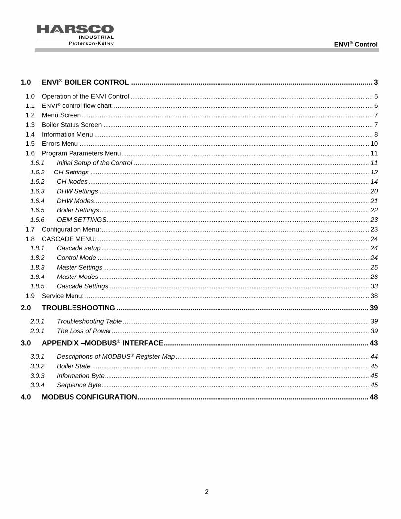
1.0 ENVI® BOILER CONTROL ...................................................................................................................... 3
1.0 Operation of the ENVI Control ...................................................................................................................................... 5
1.1 ENVI® control flow chart ................................................................................................................................................ 6
1.2 Menu Screen ................................................................................................................................................................. 7
1.3 Boiler Status Screen ..................................................................................................................................................... 7
1.4 Information Menu .......................................................................................................................................................... 8
1.5 Errors Menu ................................................................................................................................................................ 10
1.6 Program Parameters Menu ......................................................................................................................................... 11
1.6.1 Initial Setup of the Control .................................................................................................................................. 11
1.6.2 CH Settings .......................................................................................................................................................... 12
1.6.2 CH Modes ........................................................................................................................................................... 14
1.6.3 DHW Settings ..................................................................................................................................................... 20
1.6.4 DHW Modes ........................................................................................................................................................ 21
1.6.5 Boiler Settings ..................................................................................................................................................... 22
1.6.6 OEM SETTINGS ................................................................................................................................................. 23
1.7 Configuration Menu: .................................................................................................................................................... 23
1.8 CASCADE MENU: ...................................................................................................................................................... 24
1.8.1 Cascade setup .................................................................................................................................................... 24
1.8.2 Control Mode ...................................................................................................................................................... 24
1.8.3 Master Settings ................................................................................................................................................... 25
1.8.4 Master Modes ..................................................................................................................................................... 26
1.8.5 Cascade Settings ................................................................................................................................................ 33
1.9 Service Menu: ............................................................................................................................................................. 38
2.0 TROUBLESHOOTING ........................................................................................................................... 39
2.0.1 Troubleshooting Table ........................................................................................................................................ 39
2.0.1 The Loss of Power .............................................................................................................................................. 39
3.0 APPENDIX –MODBUS® INTERFACE .................................................................................................... 43
3.0.1 Descriptions of MODBUS® Register Map ........................................................................................................... 44
3.0.2 Boiler State ......................................................................................................................................................... 45
3.0.3 Information Byte .................................................................................................................................................. 45
3.0.4 Sequence Byte .................................................................................................................................................... 45
4.0 MODBUS CONFIGURATION ................................................................................................................. 48

ENVI® Control
3
1.0 ENVI® BOILER CONTROL
The ENVI® boiler control consists of 3 components and is an intelligent control system with advanced features such as text-based display, MODBUS® communication capabilities, and boiler sequencing. Firing rate and setpoint can be controlled via an external 0-10VDC analog control signal. Errors are date and time stamped, and the control records burner run time at various operating points. A single integral control for temperature control, flame safeguard, firing rate control, blocked flue protection, outdoor air reset, freeze protection, built-in cascade sequencing and more. Throughout this manual and in the ENVI® controller the term “Hysteresis” is used with the meaning of “Differential”.
The ENVI® control is capable of accepting building management control via 0-10VDC and MODBUS®. Other languages require the use of a Protocol converter which is also available separately from your Patterson-Kelley representative.
ENVI® APPLICATION
Note: The ENVI® control is capable of running the boiler on its own without any external control hardware or accessories. However, certain applications warrant the purchase and installation of separate sensors such as:
26-0000-0507 Outdoor air sensor
BP-0000-0279 Well and sensor for header and DHW applications ENVI® Control
23-0000-0539 Surface mount strap on sensor kit for header or DHW applications ENVI® Control
BP-0000-0480 Kit, 12” brass thermowell, tank temperature sensor, DHW applications ENVI® Control
10-0510-0642 Dual element immersion sensor
Optional flow switch: (necessary in some DHW applications)
86-8350-0800 Switch, flow switch
Optional aquastat: (necessary in some DHW applications)
10-0000-1209 SW,THERMO,100-200F,HONEYWELL_L6008A1242
23-0000-0233 THERMOWELL, ½” NPT
These optional sensors will enhance the performance of the ENVI® control and may be necessary to sense the locations needed for some applications to perform properly.

ENVI® Control
4
This chart represents the temperature/resistance relationship of the 12K ohm thermistor mentioned above.
The user should become thoroughly familiar with the operation of the boiler and controls before attempting to make any adjustments.
The display panel is used to setup and monitor boiler operation by means of six push buttons; MENU, BACK, ENTER, UP, DOWN, and RESET as shown.
There are shortcut functions also associated with these buttons; LIGHT, SET PT, DHW, SVC and CANCEL. The shortcut functions are available only when the default (home) screen is displayed.
The four line screen shows boiler operating information on various screens. The display screen is backlit for ease of viewing. The display panel will turn off its backlight after a period of inactivity. Press the BACK button to illuminate the screen. In a cascade system it will be necessary to make control adjustments to every boiler display panel.

ENVI® Control
5
1.0 OPERATION OF THE ENVI CONTROL
The control displays the initial boot screen (above) when first powered.
The second line of text indicates one of three possible operating configurations:
Boiler Control indicates the boiler is set up as a standalone (SA) operation (Factory default)
Master Control indicates the boiler is set up as the master in a cascade system.
Member 1 (or 2, 3, 4…) indicates the boiler is set up as a member 1 thru 24 within a cascade system.
The value shown on the fourth line of text inside the brackets [8C51] is the software version or code installed on the ENVI® boiler controls. There are several versions of the ENVI® control. These include 112E, BD71, 49A7, 79F2, 8C51,1043 and 9820. Not all features are available with all versions. Parameters which are only applicable to certain release versions will be designated accordingly. If there is no mention of versions with the parameter, then it is valid for all versions.
The control displays the default (home) screen shown above once boot up is complete. This screen displays; the date, time, boiler status, supply temperature, setpoint temperature, error codes, present operating mode (CH or DHW), CM=cascade master, or CS 01-24=cascade member (also referred to as subordinate or slave). Also, firing rate, FP (freeze protection), CL (cycle limit) and firing rate (Power) may be displayed. Cycle limit & freeze protection settings are explained later in the manual.
The control has multiple menu levels to provide set-up and operating information. Navigation through the various menus may be performed using the buttons beneath the display. The function of the buttons may be two-fold as shown below. The shortcut functions are available only when the default (home) screen is displayed.
Buttons Function Shortcut
Menu Accesses the menu None
Back / Light Returns to the previous screen Turns on backlight
Enter / Set Pt Accepts the value Accesses CH Settings
Up / DHW Increases the value/moves cursor Accesses DHW Settings
Down / SVC Decreases the value/moves cursor Accesses Service Mode
Reset / Cancel Resets the control Cancels Service Mode
Version 1.0 [8C51]
Patterson Kelley
Boiler Control
Run Power 65%
Supply 130 ° F
CH Setpt 146 ° F
Supply 130 ° F
CH Setpt 146 ° F
Feb 17 2013 04:27

ENVI® Control
6
1.1 ENVI® CONTROL FLOW CHART
Note: Parameter ranges in flow chart reference a typical MACH boiler. Parameter ranges will typically be different for a condensing vs. non-condensing boiler such as the Modufire Forced Draft boiler.

ENVI® Control
7
1.2 MENU SCREEN
From the main screen, pressing the button provides access to the following sub-menus, shown below:
Standby
Information
Errors
Program Parameters
Configuration
Cascade Menu
Service
Use the and buttons to scroll to the desired sub menu and the button to select that sub menu.
1.3 BOILER STATUS SCREEN
Pressing while in the menu screen returns the boiler status (default) screen described in Section 1.0. The default screen displays the current operating status. A list of possible operating statuses is shown below:
Standby – boiler waiting for a call for heat or for temperature conditions to require heat
Checking Air Switch – boiler is in its pre-ignition sequence, verifying the air switch is open prior to proceeding
Pre Purge - boiler is beginning the ignition sequence, purging the combustion chamber
Ignition - the igniter and gas valve are energized while flame is detected
Run – flame is established, igniter is de-energized, gas valve is controlled to satisfy heat load
Post Purge - boiler has completed the burn sequence and is purging the combustion chamber
Post Pumping – circulator pump is energized for a specified period to remove residual heat from the boiler
Reset – the ENVI® control has detected an error and locked out the boiler. (DO NOT reset the control without determining and correcting the cause)
Blocking (Alarm)-Auto reset- automatic reset lockouts that will self reset when the error condition clears.
Locking (Alarm)-Manual reset- manual reset lockouts requiring an operator to press the reset button.
If the ignition sequence is started it will be finished. Even if the demand is taken away, the sequence up to the burn state is completed.
Menu
Standby
Information Errors
Menu
Standby
Errors

ENVI® Control
8
1.4 INFORMATION MENU
Pressing at the INFORMATION menu displays the following information.
Use the and buttons to scroll through the INFORMATION menu.
Below is a list of values within the Information screen. This screen is very useful for obtaining values as it displays real time changes.
NOTE: Observe the 14°F value in the information screen above. This is the value displayed when the control recognizes an open circuit. This is common when a particular sensor such as the DHW sensor in the example above is not used, but may also occur in the event of an electrically open sensor or sensor circuit. The value displayed in the event of a shorted sensor or sensor circuit is 244°F. The values will be defined further in the following table.
Information
Supply Temp 122 ° F
Return Temp 119 ° F
DHW Temp 14 ° F
Information
Supply Temp 122 ° F
Return Temp 119 ° F
DHW Temp 14 ° F
Information
Supply Temp 122 ° F
Return Temp 119 ° F
DHW Temp 14 ° F

ENVI® Control
9
Display Description Units Open/Shorted
Sensor Indication
Supply Temp Outlet / Supply Temperature °F 14°F (Open) / 244°F(Shorted)
Return Temp Inlet / Return Temperature °F 14°F (Open) / 244°F(Shorted)
DHW Temp Domestic Hot Water Temperature at the location of the sensor(field installed)
°F 14°F (Open) / 244°F(Shorted)
Flue gas Temp
Flue Gas Temperature
FD boiler - thermal disc switch breaks the display will indicate 50F
°F 50°F (Open) / 280°F(Shorted)
HX Temp Heat Exchanger Temperature available on the MACH line C1500 thru to the C4000
°F 14°F (Open) / 244°F(Shorted)
Outside Temp Outside Air Temperature at the location of the sensor (field installed)
°F -40°F / 176°F
CH set Temp Comfort Heat Setpoint Temperature °F N/A
DHW set Temp Domestic Hot Water Setpoint Temperature °F N/A
Header Temp Header Temperature at the location of the sensor(field installed)
°F 244°F / 244°F
Flame signal Flame Signal (versions 49A7 and earlier were “YES/NO”) μA < 1.7 μA = Flame Not Detected > 1.7 μA = Flame Detected 0-10
Fan speed Fan Speed RPM 0-9999
Analog in Analog Input N/A Not Currently Used
Analog out Analog Output N/A Not Currently Used
Ignitions Number of Ignitions # 0-99999
Burn Hi HR Hours at High Fire (75% to 100%) HRS 0-99999
Burn MD HR Hours at Medium Fire (45% to 75%) HRS 0-99999
Burn LO HR Hours at Low Fire (20% to 45%) HRS 0-99999
Water press Water Pressure N/A Not Currently Used
Water level Water Level Sensor Status
Aux LWCO status on FD boilers (if installed) Off/On 0 = Low Water Cutoff
1 = Low Water Cutoff Detects Water
Low gas press Low Gas Pressure Sensor Status Off/On 0 = Low Gas Pressure Switch Open 1 = Low Gas Pressure Switch Closed
Air pressure Air Pressure Switch Status Off/On 0 = Air Pressure Switch Open 1 = Air Pressure Switch Closed
Blocked flue Blocked Flue Switch Status Off/On
0 = High Exhaust Back Pressure Switch Open 1 = High Exhaust Back Pressure Switch Closed
CH pump Comfort Heat Pump Relay Status Off/On 0 = CH Pump relay Off 1 = CH Pump relay On
DHW pump Domestic Hot Water Pump Relay Status Off/On 0 = DHW Pump relay Off 1 = DHW Pump relay On
Air damper Air Damper Relay Status Off/On 0 = Air Damper relay Off 1 = Air Damper relay On
Hi gas pressure Hi Gas Pressure Switch Status Off/On 0 = Hi Gas Pressure Switch Open 1 = Hi Gas Pressure Switch Closed

ENVI® Control
10
1.5 ERRORS MENU
Apr 20 2009 14:20 Locking IGNITION FAILURE Err:A01
Apr 20 2009 14:20 Locking IGNITION FAILURE Err:A01
Version [8C51] and earlier Versions [1043] and [9820]
The ENVI® control stores the most recent error. Version 1043 and after store the last 6 errors. These errors may be locking or blocking errors.
Pressing while in the menu screen with the cursor on Errors, the ERROR menu displays a list of the last 6
errors as shown.). Pressing and scrolls through the list of errors. Pressing while the cursor is on an error displays several lines of information about the status of the boiler during the error.
The error information recorded at the time of the error is shown in the table below.
Display Description Units
Varies Error Description N/A
Error code Error Code
Date Date Error Occurred DD-MM-YY
Time Time Error Occurred 24:00
Supply Temp Outlet Temperature °F
Return Temp Inlet Temperature °F
DHW Temp Domestic Hot Water Temperature °F
Flue gas Temp Flue Gas Temperature °F
HX Temp Heat Exchanger Temperature °F
Outside Temp Outside Air Temperature °F
Operation Mode Boiler Operation Mode (CH/DHW) °F
Days run Accumulated Days Runtime #
State State at time of error
ERRORS
Error 0 A03
Error 1 E01
Error 2 00

ENVI® Control
11
1.6 PROGRAM PARAMETERS MENU
1.6.1 Initial Setup of the Control
Press the button, scroll down with the button and select PROGRAM PARAMETERS from the menu by
pushing. A screen opens that allows access to the adjustable sub menus.
Sub Menu Description
CH settings Comfort Heat Settings: Contains settings for specific operation of the comfort heat operation. Contains the different modes of operations available. Holds the outdoor air curve and night setback settings.
DHW settings Domestic Hot Water Settings: Contains settings for specific operation of the domestic hot water capabilities.
Boiler Settings Boiler Operating Settings: Boiler settings contain the primary settings for the boilers operation.
OEM Settings Original Equipment Manufacturer Settings: These setting are non configurable and are for information only.
Selecting and editing a sub menu
Note: There are three access levels including Service Level 1, Service Level 2, and OEM settings which can be viewed, but cannot be changed in the field. Service Level 1 and Service Level 2 require access codes. Access codes are provided to those individuals who have been properly trained by Harsco Industrial, Patterson-Kelley.
CAUTION: Do not change any parameter unless the function of that parameter is thoroughly understood. Improper modification of the parameters may cause the boiler to operate erratically or not at all.

ENVI® Control
12
1.6.2 CH Settings
Parameters
CH settings
DHW settings
Boiler settings
Parameters
CH settings
DHW settings
Boiler settings
While in the PROGRAM PARAMETERS menu, press at the CH SETTINGS menu to access the comfort heat
parameters listed in the table below. Alternatively, pressing at the boiler status screen also accesses the CH
SETTINGS menu. You can now select any parameter by using the or then pressing . Each parameter can be edited by using the same buttons. Once editing of each parameter is complete
save it by pressing .
ENVI® Control
13
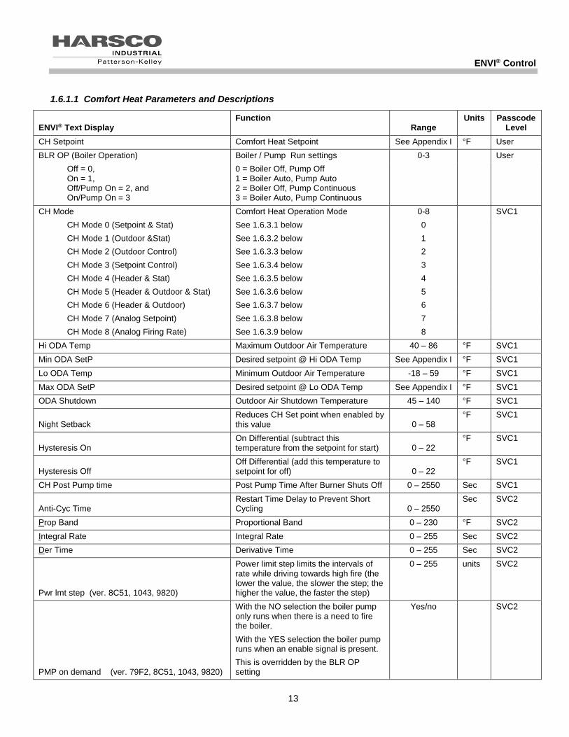
1.6.1.1 Comfort Heat Parameters and Descriptions
ENVI® Text Display Function
Range Units Passcode
Level
CH Setpoint Comfort Heat Setpoint See Appendix I °F User
BLR OP (Boiler Operation) Boiler / Pump Run settings 0-3 User
Off = 0, On = 1, Off/Pump On = 2, and On/Pump On = 3
0 = Boiler Off, Pump Off 1 = Boiler Auto, Pump Auto 2 = Boiler Off, Pump Continuous 3 = Boiler Auto, Pump Continuous
CH Mode Comfort Heat Operation Mode 0-8 SVC1
CH Mode 0 (Setpoint & Stat) See 1.6.3.1 below 0
CH Mode 1 (Outdoor &Stat) See 1.6.3.2 below 1
CH Mode 2 (Outdoor Control) See 1.6.3.3 below 2
CH Mode 3 (Setpoint Control) See 1.6.3.4 below 3
CH Mode 4 (Header & Stat) See 1.6.3.5 below 4
CH Mode 5 (Header & Outdoor & Stat) See 1.6.3.6 below 5
CH Mode 6 (Header & Outdoor) See 1.6.3.7 below 6
CH Mode 7 (Analog Setpoint) See 1.6.3.8 below 7
CH Mode 8 (Analog Firing Rate) See 1.6.3.9 below 8
Hi ODA Temp Maximum Outdoor Air Temperature 40 – 86 °F SVC1
Min ODA SetP Desired setpoint @ Hi ODA Temp See Appendix I °F SVC1
Lo ODA Temp Minimum Outdoor Air Temperature -18 – 59 °F SVC1
Max ODA SetP Desired setpoint @ Lo ODA Temp See Appendix I °F SVC1
ODA Shutdown Outdoor Air Shutdown Temperature 45 – 140 °F SVC1
Night Setback Reduces CH Set point when enabled by this value 0 – 58
°F SVC1
Hysteresis On On Differential (subtract this temperature from the setpoint for start) 0 – 22
°F SVC1
Hysteresis Off Off Differential (add this temperature to setpoint for off) 0 – 22
°F SVC1
CH Post Pump time Post Pump Time After Burner Shuts Off 0 – 2550 Sec SVC1
Anti-Cyc Time Restart Time Delay to Prevent Short Cycling 0 – 2550
Sec SVC2
Prop Band Proportional Band 0 – 230 °F SVC2
Integral Rate Integral Rate 0 – 255 Sec SVC2
Der Time Derivative Time 0 – 255 Sec SVC2
Pwr lmt step (ver. 8C51, 1043, 9820)
Power limit step limits the intervals of rate while driving towards high fire (the lower the value, the slower the step; the higher the value, the faster the step)
0 – 255 units SVC2
PMP on demand (ver. 79F2, 8C51, 1043, 9820)
With the NO selection the boiler pump only runs when there is a need to fire the boiler.
With the YES selection the boiler pump runs when an enable signal is present.
This is overridden by the BLR OP setting
Yes/no SVC2

ENVI® Control
14
1.6.2 CH Modes
There are nine CH Modes (0-8). A more detailed description of each mode is included below.
1.6.2.1 CH Mode = 0 (Setpoint & Stat)
Description Setpoint is the desired outlet water supply temperature. Upon heat demand (or enable/disable), the ENVI® control fires and modulates the boiler to maintain supply water temperature at the desired CH setpoint. The upper (HYSTERESIS OFF) and lower (HYSTERESIS ON) temperature differentials within CH settings control the temperature at which the burner turns on or off.
Example: A boiler with the following parameters (SETPOINT = 160 °F, HYSTERESIS OFF = 9 °F, HYSTERESIS ON = 10 °F) modulates to try to maintain 160° F. If the temperature increases above 169° F (160 °F SETPOINT + 9°F HYSTERESIS OFF), the boiler will shut off. Once it shuts off, it will not restart until the temperature drops below 150° F (160 °F SETPOINT – 10°F HYSTERESIS ON). This is illustrated graphically below.
The MIN SETPOINT and MAX SETPOINT parameters within the boiler settings menu limit the setpoint range. See Appendix 3.1 and 3.2 for the default values.
CH Mode 0 is recommended for all member boilers in a cascade system with the factory installed enable jumper left in place across LVTB -1 terminals 1 & 2.
In the event of failure of the master boiler the members will operate as standalone and control to their CH set points.
NOTE: The boiler is enabled by the TB1/LV terminals 1 and 2 (enable/disable) becoming closed
or shorted. This circuit is energized internally. DO NOT APPLY EXTERNAL POWER TO THESE TERMINALS.
Internal Setpoint
145
150
155
160
165
170
175
0 10 20 30 40
Time
Boiler Temperature
Boiler Set Point
Boiler Turns On
Boiler Turns Off

ENVI® Control
15
1.6.2.2 CH Mode 1 (ODA & Stat)
Outdoor Sensor required. A list of accessory choices for different applications is shown in section 1.0 on page 3. Description
In this mode, upon enabling the boiler, setpoint is varied by the outdoor air temperature (ODA). The ENVI® control
fires and modulates the boiler to maintain outlet water temperature at the setpoint which is determined by the outdoor
air temperature and its settings. The upper (HYSTERESIS OFF) and lower (HYSTERESIS ON) temperature
differentials control the temperature at which the burner turns on or off.
(FACTORY SETTINGS SHOWN ABOVE)
The Outdoor air sensor reads outdoor air temperature and sends it back to the control. The setpoint is established based on the outdoor air temperature. If the outdoor air temperature is below the (HIGH ODA TEMP), the boiler control begins to maintain a setpoint set by the (MIN ODA SETP). As the outdoor air temperature drops, the setpoint temperature increases until (LO ODA TEMP) is reached by the outdoor air temperature. When the outside air temperature has dropped to meet the (LO ODA TEMP) setting, the setpoint of the boiler will be operating at (MAX ODA SETP).
Example: Using the values in the table shown below, the boiler setpoint is 80° F (MIN ODA SETPT) when the outdoor air temperature is 70° F (HI ODA TEMP). As the outdoor air temperature drops, the boiler setpoint increases until the outdoor air temperature is 20° F (LO ODA TEMP). When this occurs, the boiler reaches its maximum setpoint of 180°F (MAX ODA SETPT). If the outdoor air temperature drops further, the boiler setpoint remains at 180° F.
Within CH Settings
Hi ODA Temp (Outdoor TMax) 70 °F
Min ODA SetP (Setpoint TMin) 80 °F
Low ODA Temp (Outdoor TMin) 20 °F
Max ODA Setp (Setpoint TMax) 180 °F
ODA shutdown 68 °F
NOTE: The boiler is enabled by the TB1/LV terminals 1 and 2 (enable/disable) becoming closed or shorted. This circuit is energized internally. DO NOT APPLY EXTERNAL POWER TO THESE TERMINALS.
NOTE: while using CH MODE 1 (ODA&STAT) the ODA shutdown temperature is ignored and does not
stop the boiler from running.

ENVI® Control
16
1.6.2.3 CH Mode 2 (Outdoor Control)
Outdoor Sensor required. A list of accessory choices for different applications is shown in section 1.0 on page 3.
Description
In this mode, setpoint is varied by the outdoor air temperature (ODA). Upon enabling the boiler, the ENVI® control
fires and modulates the boiler to maintain outlet water temperature at the setpoint determined by the outdoor air
temperature and its settings. The upper (HYSTERESIS OFF) and lower (HYSTERESIS ON) temperature differentials
control the temperature at which the burner turns on or off.
Notes: Reference table and graph in section 1.6.2.2 for example of ODA to Boiler Temp relationship.
NOTE: The boiler is enabled when the temperature of the outdoor sensor drops below the ODA
SHUTDOWN temperature that can be changed within the CH settings.
The TB-1/LV terminals 1 and 2 (enable/disable) operate the switching on/off of the night setback function.
The night setback setpoint is set within CH settings and reduces the CH set point by its value while
enabled. (TB-1/LV terminals 1 and 2 circuit closed)
1.6.2.4 CH Mode 3 (Setpoint Control)
Description In this mode, the boiler functions as described in 1.6.2.1, CH Mode 0, except that the external thermostat does not create the call for heat. The closure of TB1/LV terminals 1 and 2 will reduce the CH setpoint by the value of the night setback setting.
Example: Using the values, CH SP=180° F and Night Setback=10° F, when TB1/LV terminals 1 and 2 are open the CH setpoint will be 180° F. When TB1/LV terminals 1 and 2 are closed the CH setpoint will be 170° F (180° F -10° F).
NOTE: In this mode the boiler will always run to setpoint, since there is no enable circuit closure required.
The TB-1/LV terminals 1 and 2 (enable/disable) operate the switching on/off of the night setback function.
The night setback setpoint is set within CH settings and reduces the CH set point by its value while
enabled. (TB-1/LV terminals 1 and 2 circuit closed)
1.6.2.5 CH Mode 4 (Header & Stat) This mode is preferred for the master boiler in a cascade system.
A sensor will be needed to sense header temperature. A list of accessory choices for different applications is shown in section 1.0 on page 3.
Description In this mode, the boiler functions as described in 1.6.3.1, CH Mode 0, except that the boiler maintains the setpoint temperature where the header sensor is located.
NOTE: The boiler is enabled by the TB1/LV terminals 1 and 2 (enable/disable) becoming closed or
shorted. This circuit is energized internally. DO NOT APPLY EXTERNAL POWER TO THESE TERMINALS.
Note: Placing the master boiler in CH mode 4 on any cascade application will show the header temperature (HDR Supply) on the display in the place of the supply temperature on the third line of text on the master boiler.

ENVI® Control
17
1.6.2.6 CH Mode 5 (Header & ODA & Stat)
Two sensors are required to sense header temperature and outdoor temperature. A list of accessory choices for different applications is shown in section 1.0 on page 3. Description This mode is a combination of CH Mode 1 (ODA & Stat) and CH Mode 4 (Header & Stat). When the boiler is enabled through TB1/LV terminals 1 and 2, the setpoint temperature is maintained at the location of the header sensor based on the ODA reset schedule that is determined from the optional outdoor air sensor.
Note: While using CH MODE= 5 (HEADER&ODA&STAT) the ODA shutdown temperature is ignored and does not
stop the boiler from running.
Note: Reference table and graph in section 1.6.2.2 for example of ODA to Header Temp relationship.
Note: Placing boiler in CH mode 5 will show the header temperature (HDR Supply) on the display in the place of the supply temperature on the third line of text on the boiler.
1.6.2.7 CH Mode 6 (Header & Outdoor)
Two sensors are required to sense header temperature and outdoor temperature. A list of accessory choices for different applications is shown in section 1.0 on page 3. Description This mode is a combination of CH Mode 2 (Outdoor Control) and CH Mode 4 (Header & Stat). The temperature is maintained at the location of the header sensor and the setpoint is based on the ODA reset schedule that is determined from an outdoor air sensor and the night setback feature. The closure of TB1/LV terminals 1 and 2 will reduce the CH setpoint by the value of the night setback setting.
Note: In this mode the boiler will always run to setpoint, as there is no enabling needed using this CH mode.
Note: Reference table and graph in section 1.6.2.2 for example of ODA to Header Temp relationship.
Example: Using the values, CH SP=180° F and Night Setback=10° F, when TB1/LV terminals 1 and 2 are open the
CH setpoint will be 180° F. When TB1/LV terminals 1 and 2 are closed the CH setpoint will be 170° F (180° F -10° F).
NOTE: The boiler is enabled when the temperature of the outdoor sensor drops below the ODA
SHUTDOWN temperature which can be changed within the CH settings.
NOTE: The TB1/LV terminals 1 and 2 (enable/disable) operate the switching on/off of the night setback
function. The night setback setpoint is set within CH settings.
NOTE: The boiler is enabled by the TB1/LV terminals 1 and 2 (enable/disable) becoming closed or shorted.
This circuit is energized internally. DO NOT APPLY EXTERNAL POWER TO THESE TERMINALS.

ENVI® Control
18
1.6.2.8 CH Mode 7 (Analog Control of Setpoint)
Description In this mode, an external 0-10 VDC signal controls the setpoint of the boiler. From the factory, the Min Setpoint is set for 42° F for condensing boilers (130° F for non-condensing) and the Max Setpoint is set for 185° F for condensing boilers (220° F for non-condensing). Applying a voltage of at least .5 to 1.5 VDC creates the heat request. Applying 2 VDC sets the boiler setpoint to BOILER MIN SETPOINT. Applying 10 VDC sets the boiler setpoint to BOILER MAX SETPOINT. Applying less than .5 VDC removes the heat request. The Min and Max set points can be adjusted within the boiler settings menu.
NOTE: When in analog control mode, enable/disable terminals are non-functional as the boiler is enabled/disabled by applying .5 to 1.5 VDC. Dropping below .5VDC will disable the boiler.
Many times the building automation sequence of operation requires an enable/disable circuit; this can be achieved by installing a relay in series with the control signal and opening the contacts to drop voltage to 0VDC thereby disabling the boiler. A normally closed contact will provide fail safe operation.

ENVI® Control
19
1.6.2.9 CH Mode 8 (Analog Control of Firing Rate)
Description
In this mode, an external 0-10 VDC signal from the building automation system or some external control determines the firing rate of the boiler. A signal of .5 to 1.5VDC generates a heat request and is required to start the boiler. At 2 VDC the firing rate is 20% and at 10 VDC the firing rate is 100%.
Boiler temperature limits and safety features are still active. Although the boiler may be receiving a 10 VDC signal, high fire will not be achieved if certain parameters, such as the boiler maximum temperature, are exceeded.
NOTE: When in analog control mode, enable/disable terminals are non-functional as the boiler is enabled/disabled by applying .5 to 1.5 VDC. Dropping below .5VDC will disable the boiler.
Many times the building automation sequence of operation requires an enable/disable circuit; this can be achieved by installing a relay in series with the control signal and opening the contacts to drop voltage to 0VDC thereby disabling the boiler. A normally closed contact will provide fail safe operation.

ENVI® Control
20
1.6.3 DHW Settings
Parameters
CH settings
DHW settings
Boiler settings
Parameters
CH settings
DHW settings
Boiler settings
From the PARAMETERS menu use and to move the cursor to DHW settings then press to
access the domestic hot water parameters listed in the table below. Alternatively, pressing at the default (home) screen also accesses the DHW SETTINGS menu.
1.6.3.1 Domestic Hot Water (DHW) Parameters and descriptions
ENVI® Text Display Function Range Units Passcode
Level
DHW mode None = 0 Storage & Sensor = 1 Storage & Stat = 2 Plate HX = 3
Type of System 0 = No Domestic Hot Water 1 = Storage Tank with Temperature Sensor 2 = Storage Tank with Thermostat 3 = Plate Heat Exchanger w/Flow Switch
0 – 3
SVC1
DHW Type CH/DHW = 0 DHW Priority = 1 3 Way Valve NC = 2
Domestic Hot Water Operation Type 0 = Simultaneous CH and DHW Pumps 1 = DHW pump has priority over CH pump 2 = 1 Boiler Pump: when 3 way valve Normally Closed = DHW when 3 way valve Powered Open = CH
0 – 2 SVC1
DHW setpoint Setpoint for Domestic Hot Water Output 86 – 185 °F User
Tank set Setpoint of Storage Tank (DHW mode 1) 104 –162 °F User
ON different Boiler On Differential 0 – 36 °F SVC1
OFF different Boiler Off Differential 0 – 36 °F SVC1
Tank off dif Tank Off Differential (DHW mode 1) 0 – 36 °F SVC1
Tank on diff Tank On Differential (DHW mode 1) 0 – 36 °F SVC1
Post pmp Time DHW Post Pump Time 0 – 255 Sec SVC1
Prop band Proportional Band 0 – 230 °F SVC2
Integral RTE Integral Rate 0 – 255 Sec SVC2
DER time Derivative Time 0 – 255 Sec SVC2
Pwr lmt step
(ver. 8C51, 1043)
Power limit step limits the intervals of rate while driving towards high fire (the lower the value, the slower the step; the higher the value, the faster the step)
0 – 255 units SVC2
PMP on demand
(ver. 79F2, 8C51, 1043)
With the NO selection the boiler pump only runs when there is a need to fire the boiler. With the YES selection the boiler pump runs when an enable signal is present. This is overridden by the BLR OP setting
No / Yes SVC2
Priority Time
(ver. 79F2, 8C51, 1043)
The maximum amount of time the domestic hot water operation has priority over the comfort heat operation. Timer is reset and starts when the domestic hot water call is enabled.
0 – 255 Min SVC1

ENVI® Control
21
1.6.4 DHW Modes
The DHW system designs that can be accommodated by this control include:
DHW mode 1- a storage tank with temperature sensor
DHW mode 2- a storage tank with thermostat
DHW mode 3- a plate heat exchanger
Mach boilers, N Series Modufire boilers, and P-K Sonic Boilers can NOT be used for direct fire DHW
applications. These boilers require an isolating heat exchanger between the potable water and the non-potable boiler loop.
D series Modufire boilers and Mach ‘n Roll™ boiler packages can be used for direct potable water contact in the DHW mode.
1.6.4.1 DHW Mode 1 (Storage & Sensor) Storage Tank with Temperature Sensor
Tank Sensor required. A list of accessory choices for different applications is shown in section 1.0 on page 3. Description A storage tank equipped with a temperature sensor is connected to the boiler. The 12K ohm NTC sensor must be wired into the boiler at the DHW sensor terminals (Typically terminals 7 & 8 on TB-1). When the temperature sensor reads that the tank temperature is below the TANK SET parameter by the TANK ON DIFF, the DWH pump circuit is energized and the boiler starts and supplies heat to the tank. The boiler modulates the firing rate to maintain the DHW SETPOINT at the boiler outlet. When the temperature in the tank exceeds the TANK SET parameter by the TANK OFF DIFF, the boiler shuts off the burner and the DHW pump continues to run for a pre-set time (POST PMP TIME). Note: Proper sizing of the storage tank is important to prevent short cycling of the boiler equipment. Check with your authorized Patterson-Kelley Representative for assistance on tank sizing.
1.6.4.2 DHW Mode 2(Storage & Stat) Storage Tank with Thermostat
Installer needs to supply a closure device (aquastat, thermostat, flow switch, etc.) to close the DHW Enable circuit
(Typically terminals 7 & 8 on TB-1). A list of accessory choices for different applications is shown in section 1.0 on page 3 Description A storage tank equipped with a thermostat is connected to the boiler. When the closure device creates a closed state, the DWH pump circuit is energized and the boiler starts and supplies heat to the tank. The boiler modulates the firing rate to maintain the DHW SETPOINT at the boiler outlet. When the closure device opens, the boiler shuts off the burner and the DHW pump continues to run for a pre-set time (POST PMP TIME).
1.6.4.3 DHW Mode 3 (Plate Heat Exchanger) Heat Exchanger without Storage
Installer needs to provide a flow-proving device (flow switch) and a temperature sensor. A list of accessory choices for different applications is shown in section 1.0 on page 3. Description A plate heat exchanger equipped with a DHW flow proving device and a temperature sensor is connected to the boiler. When the flow-proving device closes, it creates a call for heat and the boiler’s DHW Pump Contactor terminals close which starts the boiler DHW pump. If the DHW water temperature is below the DHW SETPOINT by the ON DIFFERENTIAL, the boiler fires and supplies heat to the exchanger. The boiler modulates the firing rate to maintain the DHW SETPOINT at the boiler outlet. When the temperature of the boiler water rises above the DHW SETPOINT by the OFF DIFFERENTIAL, the boiler shuts off the burner and the boiler DHW pump continues to run for a pre-set time (POST PMP TIME). When the demand is satisfied, the flow-proving device breaks the call for heat.

ENVI® Control
22
1.6.5 Boiler Settings
Boiler Settings Parameters and descriptions
Note: xxxx is dependent upon model of the boiler.
ENVI® Text Display
Function Range Units Passcode
Level
Boiler type Selects the type of boiler. xxxx xxxx OEM
Max Fan Speed (ver. 112E, BD71, 49A7, 79F2,8C51)
Selects the absolute maximum fan speed xxxx RPM SVC2
CH Max fan
(ver. 1043,9820) Selects the maximum allowable boiler CH fan speed. xxxx RPM SVC2
DHW Max fan
(ver. 1043,9820)
Selects the maximum allowable Domestic Hot Water fan speed.
xxxx RPM SVC2
Min fan spd Selects the minimum fan speed. xxxx RPM SVC2
Max setpoint Selects the maximum allowable setpoint xxxx °F SVC2
Min setpoint Selects the minimum allowable setpoint xxxx °F SVC2
Max Temp Selects the maximum allowable water temperature xxxx °F SVC2
Mod back dif
Modulation back differential is the differential temperature (Supply temperature – Return temperature) allowable before MBD offset begins to modulate the boiler.
0 – 64 °F SVC2
MBD offset
Modulation Back Differential Offset is a temperature buffer before the boiler drops completely to low fire. Example: 45°F (MBD) + 5°F (MBD Offset) = 50°F at which time the boiler will drop to low fire. Inside of this 5°F range it will step modulate to buffer out an application where the boiler flow may dip just beyond minimum flow for a short period of time. This stabilizes the modulation.
0 – 64 °F SVC2
Lo fire hold Upon ignition, the boiler drives to low fire and holds for this amount of time.
0 – 255 Sec SVC2
Post purge This is the amount of time the fan runs after the burner has shut off.
0 – 255 Sec SVC2
Accel BNR ON Selects the fire rate ramp up speed upon power increase rate (lower=slower)
1-15 units SVC2
Accel BNR OFF Selects the fire rate ramp down speed upon power decrease rate (lower=slower)
1-15 units SVC2
FP Always enabled (ver. 112E, BD71)
FP on/off ( (High settings)
(ver. 49A7, 79F2)
FP enable (ver. 8C51, 1043)
Frost Protection forces the CH pump and burner to run. The Burner will run until the lowest of both supply and return temperature measures above 59°F.
HIGH: pump runs at 50° F
Burner runs at 42° F
LOW: pump runs at 30° F (GLYCOL APPLICATION)
Burner runs at 22° F
High
Low
Off
°F SVC2
Pwr Lmt Step
(ver. 79F2)
Power limit step limits the intervals of rate while driving towards high fire (the lower the value, the slower the step; the higher the value, the faster the step)
0 – 255 units SVC2

ENVI® Control
23
1.6.6 OEM SETTINGS
The OEM Settings are password protected by a numerical code and should only be changed by Harsco Industrial, Patterson-Kelley personnel.
The only adjustable parameter within OEM settings will be IGN fan speed. To change this parameter use the service level code 2.
1.7 CONFIGURATION MENU:
The CONFIGURATION menu is a general menu that allows selection of the display language, date/time, code, °F/°C temperature selection and MODBUS® address.
Use and to move the cursor to the desired setting then press to access for adjustment. LANGUAGE options include English, French or Spanish. English is the default language. ENVI translation to French or Spanish text has not been developed in any version to date. DATE TIME is factory set at the current date & time in the Eastern time zone at the time of production. The ENVI Display has a long life battery that will store this information. Date & time should be changed to reflect actual time zone, daylight savings time, etc. CODE configuration indicates the display panel software version. ° F or ° C configuration allows the user to select Fahrenheit or Celsius. MODBUS® ADDRESS configuration allows the user to set the Modbus® device identification. Each ENVI control defaults to Modbus® address 1. In applications with multiple boilers, it is necessary to assign distinct addresses to each boiler when Modbus® communication is used. Section 1.8 will address the cascade menu: There are two separate polarity sensitive communication paths each referred to as a “bus”. For clarification purposes it is important to understand that the member boilers transfer data to & from the master boiler via the Cascade bus which could be described as an internal bus of the cascade boiler system. The Modbus circuit, which could best be described as an external bus, is a total separate communication path and transfers data to and from all connected boilers, not with each other, but with an external communication system such as a building management system utilizing the Modbus protocol. Communication with other protocols can be established using a protocol converter. Your local Patterson-Kelley Representative can provide information on the Protonode protocol converter that is designed for use with the ENVI control.
Menu
Errors
Program Parameters
Configuration
Menu
Errors
Program Parameters
Configuration

ENVI® Control
24
1.8 CASCADE MENU:
1.8.1 Cascade setup
With the power off, you can connect up to 24 boilers into the ENVI® Cascade system. Wires are connected from the Cascade terminals (A & B) on the master boiler to the Cascade terminals (A & B) on the member (subordinate
or slave) boilers. Connect A to A and B to B. The boilers are connected in series (daisy chain topology) using 18/2 shielded wiring. The wire shield should be grounded on one end only (typically at the master) and the shield connected together and insulated from ground for the rest of the wiring. The result will be a continuous shield grounded on one end only.
After making the boiler to boiler connections, select one boiler as the master boiler. Remove the interface cover (if present) and confirm the master/member selector switch is set to the MASTER position (factory set to member position). Ensure that the remaining member boiler switches are set to the MEMBER position. A picture of the master/member selector switch is shown to the left. Note: the MASTER position is away from the blue transformer, while the MEMBER position is towards the blue transformer. The
orientation of the board may vary from the picture shown.
CAUTION! Setting more than one master/member selector switch to the MASTER position may damage the control and cause incorrect operation.
Turn the power on. Press button and scroll down to Cascade menu, then press . Then you will see These settings include: CONTROL MODE, MASTER SETTINGS, CASCADE SETTINGS, INFORMATION ERRORS.
1.8.2 Control Mode
In this menu, the operational mode is selected.
Single boiler control – SA (stand-alone) as shown in example above Cascade Master - CM Cascade member (subordinate or slave) – CS01, CS02, etc.
When the boiler is set as master, the cascade address shall be automatically set to 0. When the mode is set as member (slave), the user enters a unique address (1-23) for each boiler. For Example: Boiler 1 (Master) = Cascade address 0, Boiler 2 (Slave) = Cascade address 1, and Boiler 3 (Slave)= Cascade address 2.
Note: A boiler selected as a cascade member and not connected to a master or with the master powered down, will result in a NO COMM error.
Member
------------
Master
Switch
Cascade Menu Control Mode SA
Master Settings
Cascade Settings

ENVI® Control
25
1.8.3 Master Settings
These settings can only be accessed on a designated master boiler. The master settings are used in conjunction with the cascade settings to set the system response parameters.
These settings are described in more detail below.
ENVI® Text Display Function Range Units Pass code
Level
HDR Setpoint Sets the operating
temperature at the header 104 – 194 °F SVC2
Power Mode 0 – 1 SVC2
Power Mode Min Boilers On
See Below 1.8.4.1 0
Power Mode Max Boilers On
See Below 1.8.4.2 1
Header Mode 0 – 4 SVC2
Header Mode (Header & Stat)
See Below 1.8.4.3 0
Header Mode (Header ODA & Stat)
See Below 1.8.4.4
1
Header Mode (Header & ODA)
See Below 1.8.4.5 2
Header Mode (HDR Setpt Control)
See Below 1.8.4.6 3
Header Mode (HDR Analog Setpt)
See Below 1.8.4.7 4
Hyst Start Blr See Below 1.8.4.8.1 0 – 36 °F SVC2
Hyst Stop Blr See Below 1.8.4.8.2 0 – 36 °F SVC2
Wait Blr Swtch
(ver. 112E, BD71, 49A7)
See Below 1.8.4.8.3 1 – 255 Sec SVC2
Wait Blr Sw on
(ver. 79F2, 8C51, 1043, 9820)
See Below 1.8.4.8.4 1 – 60
Min SVC2
Wait blr sw pwr
(ver. 1043, 9820)
See Below 1.8.4.8.5 0-100% SVC2
Wait Blr sw off
(ver. 79F2, 8C51, 1043, 9820)
See Below 1.8.4.8.6 1 – 60
Min SVC2
Wait reset time
(ver. 8C51, 1043, 9820) See Below 1.8.4.8.7
On/off SVC2
Prop Band (Proportional Band)
Proportional Band 0 – 230 °F SVC2
Integral Rate Integral Rate 0 – 255 Sec SVC2
Der Time (Derivative) Derivative Time 0 – 255 Sec SVC2
Cyc Lmt Incrmnt See Below 1.8.4.8.11 0 – 50 Min SVC2
Cycl Limit Max See Below 1.8.4.8.12 1 – 255 Min SVC2
Hys Quic Start See Below 1.8.4.8.13 0 – 51 °F SVC2

ENVI® Control
26
ENVI® Text Display Function Range Units Pass code
Level
Quic Start Tme See Below 1.8.4.8.13 1 – 255 Sec SVC2
Hys Quick Stop See Below 1.8.4.8.13 0 – 51 °F SVC2
Quic Stop Time See Below 1.8.4.8.13 1 – 255 Sec SVC2
LoLoad Waiting See Below 1.8.4.8.14 0 – 255 Sec SVC2
Start Rotation
(ver. 112E, BD71, 49A7, 79F2, 8C51)
(ver. 1043, 9820)
See Below 1.8.4.8.15 Off
On:1-255
On:1-255
Hours
Days
SVC2
No Blr on Wait See Below 1.8.4.8.16 1 – 255 Min SVC2
Anti wind up See Below 1.8.4.8.17 On/off SVC2
Lead boiler
(ver. 1043, 9820)
See Below 1.8.4.8.18 0 - 23 SVC2
1.8.4 Master Modes (a more detailed description of Power Modes can be found in section 1.8.5.1.1)
1.8.4.1 Power mode = 0, Min Boilers on (typically not the most efficient of the two power mode options)
In this mode, when more than two boilers are required to satisfy the load, the last two boilers on will run to 100% as needed. All other boilers will modulate in parallel. This satisfies the load with the minimum amount of boilers firing (Less efficient operation).
Example: BLR 1 on 100%, BLR 2 on 100%, as BLR 3 comes on BLR 1 will begin to modulate as BLR 3 runs to 100% when BLR 4 comes on and runs to 100%, BLR 2 will begin to modulate. This sequence will continue until the demand is satisfied. The staging procedure is first on, last off.
Power mode = 1, Max Boilers On (Parallel Modulation – Default Setting)
In this mode, the boilers modulate in parallel based on a signal from the master boiler. This satisfies the load with the necessary number of boilers firing at the lowest fire rate possible resulting in more efficient operation in most cases.
The staging procedure is first on, last off.
1.8.4.2 Header Mode = 0, (Header & Stat)
Sensor kit required to sense header temperature. A list of accessory choices for different applications is shown in section 1.0 on page 3.
In this mode, the master boiler controls the operation of all the boilers in the cascade system to maintain a supply temperature where the header sensor is located. Upon an enable signal, from the closure between terminals TB1-1 & TB1-2, the ENVI® control on the Master boiler fires and modulates the boilers to maintain header water temperature at the header setpoint. The upper (HYST STOP BLR) and lower (HYST START BLR) temperature differentials in conjunction with other cascade settings control the header temperature at which boilers are added or removed. Example: The Master boiler operates the system to maintain the header setpoint of 160° F. If the temperature increases above 170° F (setpoint 160° F + 10°F HYST STOP BLR), a boiler will shut off. If the temperature decreases below 151°F (setpoint 160°F – 9°F HYST START BLR), another boiler will start.
NOTE: The cascade system is enabled by the TB1/LV terminals 1 and 2 (enable/disable) on the master boiler becoming closed or shorted. This circuit is energized internally. DO NOT APPLY EXTERNAL POWER TO THESE TERMINALS.

ENVI® Control
27
1.8.4.3 Header Mode = 1, (Header ODA & Stat)
Sensor kits required to sense header & outdoor temperatures. A list of accessory choices for different applications is shown in section 1.0 on page 3. In this mode, the temperature is maintained at the location of the header sensor based on a reset schedule that is determined from an outdoor air sensor. The parameters for changing the reset schedule are in PROGRAM PARAMETERS>CH SETTINGS. An external thermostat wired to the enable/disable circuit controls the heat demand. Upon an enable signal from the closure between terminals TB1-1 & TB1-2, the ENVI® control on the Master boiler fires and modulates the boilers to maintain header water temperature at the header setpoint which changes based on outdoor temperature. The upper (HYST STOP BLR) and lower (HYST START BLR) temperature differentials in conjunction with other cascade settings control the header temperature at which boilers are added or removed.
NOTE: The outdoor air shutdown does not prevent the boiler from running in this mode.
NOTE: The cascade system is enabled by the TB1/LV terminals 1 and 2 (enable/disable) on the master boiler becoming closed or shorted. This circuit is energized internally. DO NOT APPLY EXTERNAL POWER TO THESE TERMINALS.
1.8.4.4 Header Mode = 2, (Header & ODA)
Sensor kits required to sense header & outdoor temperatures. A list of accessory choices for different applications is shown in section 1.0 on page 3.
In this mode, the temperature is maintained at the location of the header sensor based on a reset schedule that is
determined from the outdoor air sensor. The parameters for changing the reset schedule are in PROGRAM
PARAMETERS>CH SETTINGS.
The boiler is enabled when the temperature of the outdoor sensor drops below the ODA SHUTDOWN temperature
that can be changed within the CH settings.
NOTE: The TB1/LV terminals 1 and 2 (enable/disable) operate the switching on/off of the night setback function. The
night setback setpoint is found within CH settings and when enabled, reduces the present set point by its value on
closure of the TB1 1&2 circuit. This circuit is energized internally. DO NOT APPLY EXTERNAL POWER TO THESE TERMINALS.
1.8.4.5 Header Mode = 3, (Header Setpoint Control)
Sensor kit required to sense header temperature. A list of accessory choices for different applications is shown in section 1.0 on page 3. This mode is similar to Header Mode = 0, Header & Stat, described in 1.8.3.3, except there is no external thermostat. The heat demand is continuously maintained and controlled by the header sensor and header setpoint relations.
NOTE: The TB1/LV terminals 1 and 2 (enable/disable) operate the switching on/off of the night setback function. The
night setback setpoint is found within CH settings and when enabled, reduces the present set point by its value on
closure of the TB1 1&2 circuit. This circuit is energized internally. DO NOT APPLY EXTERNAL POWER TO THESE TERMINALS.

ENVI® Control
28
1.8.4.6 Header Mode = 4, (HDR Analog Setpoint)
Sensor kit required to sense header temperature. A list of accessory choices for different applications is shown in section 1.0 on page 3. In this mode, an external 0-10 VDC signal controls the setpoint of the cascade system at the Master boiler. Applying a voltage of at least 0.5 to 1.5VDC creates the heat request. Applying 2 VDC sets the boiler setpoint to “Min Setpoint”. Applying 10 VDC sets the boiler setpoint to “Max Setpoint”. Applying less than 0.5 VDC removes the heat request. The BLR Min Setpoint and BLR Max setpoint parameters can be adjusted within boiler settings.
The boiler is factory set for min 42⁰F max 180⁰F as displayed in the below graph.
1.8.4.7 Additional Master Settings
1.8.4.7.1 Hyst start blr {Hysteresis start boiler}
This is the differential below header setpoint at which the master control will initiate the WAIT BOILER SWITCH ON timer to request the next member boiler to run. When the HEADER TEMPERATURE drops below the HEADER SETPOINT minus the HYSTERESIS START BOILER, the WAIT BOILER SWITCH ON timer begins counting down. When the timer expires, the member boiler is requested to fire and the WAIT BOILER SWITCH ON timer resets.
1.8.4.7.2 Hyst stop blr {Hysteresis stop boiler}
This is the differential above header setpoint at which the master control will stop a member boiler. When HEADER TEMPERATURE exceeds the HEADER SETPOINT plus the HYSTERESIS STOP BOILER, the WAIT BOILER SWITCH OFF timer begins counting down. When the timer expires, the member boiler is stopped and the WAIT BOILER SWITCH OFF timer resets.
NOTICE! When in analog control mode, enable/disable terminals are non-functional.
Minimum
setpoint
Maximum
setpoint
NOTICE! Minimum and maximum
setpoints can be changed within Boiler
Settings menu.

ENVI® Control
29
1.8.4.7.3 Wait blr swtch {Wait boiler switching}
This parameter is the time the master boiler control waits to watch the effect of a change in the number of boilers operating, before making another change. Not available on all revisions.
1.8.4.7.4 Wait blr sw on {Wait boiler switch on}
This parameter is the time the master control waits to watch the effect of a change in the number of boilers operating, before making another change ON. See above 1.8.4.8.1 for descriptive example.
1.8.4.7.5 Wait blr sw pwr {Wait boiler switch power}
This is the power setting in 0-100% that the master boiler will wait for the last started boiler to achieve before switching on the next boiler in the cascade system. (Set to 100% to deactivate)
1.8.4.7.6 Wait blr sw off {Wait boiler switch off}
This parameter is the time the master boiler control waits to watch the effect of a change in the number of boilers operating, before making another change OFF. See above 1.8.4.8.2 for descriptive example.
1.8.4.7.7 Wait reset time
In versions 1043 & 9820 this feature allows the WAIT BOILER SWITCH ON timer and WAIT BOILER SWITCH OFF timer to reset back to zero, or pause at that current point whenever a heating cycle is complete.
This on/off setting allows the wait time to:
ON = resets time for sequence every time a reduction in heat load occurs back to zero
OFF = pauses time for sequence every time a reduction in heat load occurs.

ENVI® Control
30
The following sections 1.8.4.8.8 through 1.8.4.8.10 are intended to provide a basic overview of the PID control algorithm as it applies to the ENVI control. The default PID settings in the ENVI are based on tested application experience with P-K boilers in various hydronic systems. The default settings will be best suited to most P-K boiler applications.
Simply put, these values can be interpreted as a timeline: P depends on the present error, I on the accumulation of past errors, and D is a prediction of future errors, based on current rate of change
1.8.4.7.8 Prop band {Proportional band}
This parameter in the ENVI is the temperature range in degrees throughout which the logic of the boiler control proportionally modulates the reaction of the boiler to the deviation from setpoint.
Proportional band in the ENVI is biased by the adjustment of Derivative time setting.
Commonly referred to as the throttling range, proportional band is defined as the amount of change in the controlled variable required to drive the loop output from 0 to 100%. For example: With the proportional band left at the default setting of 20° and a header setpoint of 140°:
With the Derivative time set at the default setting of 128 or higher (default setting) the proportional band is below the setpoint (figure 2)
If the header temperature drops to130° (10° below SP) The proportional action of the control will be 50%. If the header temperature drops to120° (20° below SP) The proportional action of the control will be 100%.
OR: With the proportional band left at the default setting of 20° and a header setpoint of 140°:
With the Derivative time set at 0 (and up to 127), the proportional band is symmetrical around the setpoint (figure 1)
If the header temperature drops to130° (10° below SP) The proportional action of the control will be 100%. If the header temperature reaches 140° (SP) The proportional action of the control will be 50%.
As the header temperature rises above 140° (10° above SP) The proportional action of the control will decrease output to 0% until reaching 10°
above setpoint. (50% of proportional band)
Figure 1 setpoint Figure 2(default) setpoint
Proportional Band Proportional Band

ENVI® Control
31
1.8.4.7.9 Integral rate
This parameter in the ENVI is the time in seconds that the boiler control calculates the deviation from setpoint and responds to drive the output towards setpoint. The I-term is the integration factor as it applies to the ENVI. Every second the error between sensor input and setpoint is added to the sum of errors. This sum, divided by the I-term and added to the output power generated by the P-factor as described above. So if the sensor input stays below the setpoint this internally calculated sum increases and therefore the SUM divided by I-term increases so the PID output increases. If you increase this value the input of this sum of errors reduces and the system becomes slower.
For example: With an Integral rate at the default setting of 50 and a header setpoint of 140°: If the header temperature is at 130° (10° below SP) the integral rate of adjustment will add 0.2° to the setpoint. 10(degrees below setpoint) ÷ 50(Integral rate) = 0.2 The ENVI control will add 0.2° to the setpoint making the effective setpoint 140.2°
(By changing the effective setpoint in the logic, this increases the action towards setpoint)
Integral rate continues to adjust the control output in accordance with both the size of the deviation from setpoint and the time it lasts to bring the process to setpoint regardless of load
1.8.4.7.10 Der time {Derivative time}
Derivative time setting in the ENVI control serves as a bias setting for the Proportional band. If the Derivative time setting is at the default setting of 128 or above, the proportional band is below the setpoint. See figure 2 on page 30. If the Derivative time setting is at the alternate setting of 0 up to 127, the proportional band is
symmetrical around the setpoint. See figure 1 on page 30.
1.8.4.7.11 Cyc lmt incrmnt {Cycle limit increment}
Each time a starting or stopping of a boiler is detected, a cycle limit increment is added to the switch boiler counter. Every minute of cycle run time this counter is decreased by one (1). Only if the switch boiler counter value is below Cycle limit max can boilers be switched on or off. This feature prevents the boilers from short cycling, leading to increased boiler lifespan.
1.8.4.7.12 Cycl limit max {Cycle limit max}
This parameter is the maximum amount of time allowed for the boiler to short cycle based on the cycle limit increment parameter and the switch boiler counter value. Once the switch boiler counter

ENVI® Control
32
exceeds this setting, CL will be displayed in the lower left of the ENVI display and the boiler will be unable to cycle until the switch boiler counter is below this parameter again. Every minute of cycle run time this counter is decreased by one (1).
1.8.4.7.13 Hys quic start {Hysteresis quick start}, Quic start tme {Quick start time}, Hys quick stop {Hysteresis quick stop}, Quic stop time {Quick stop time}
For those instances where the load changes rapidly quick start / quick stop parameters bypass the Wait blr sw on and Wait blr sw off parameters to allow the system to respond more quickly.
When the header temperature falls below the HDR SETPOINT by the HYS QUIC START temperature setting, the control uses the QUIC START TIME (time delay for quick start) to stage on member boilers. The master control shortens the interval between boiler starts, allowing the system to catch up more quickly.
When the header temperature rises above HDR SETPOINT by the HYS QUIC STOP temperature setting, the control uses the QUIC STOP TIME (time delay for quick stop) to stop the member boilers. The master control shortens the interval between boiler stops, allowing the system to prevent overshooting the HDR SETPOINT.
1.8.4.7.14 Lo Load waiting {Low Load Waiting}
The LOLOAD WAITING is set on the master boiler control and used in conjunction with the various other low load settings found in the cascade menu on the member boiler(s). This parameter allows the master to turn on a boiler that is below the HDR SETPOINT temperature if this time interval has passed. The master sends the header setpoint to the member boilers; each member boiler control monitors its own supply temperature to detect if a low load condition exists.
This and additional low load settings are described in the Cascade Settings section of this manual.
1.8.4.7.15 Start rotation
The START ROTATION is an On/Off selection. When this selection is ON; a sub-setting is required to be defined to determine the frequency of lead rotation from the current operating lead to the next boiler. The Master boiler will always remain the master and will be the lead boiler initially, after each rotation frequency period elapses, the next sequential boiler will rotate as the lead boiler. This rotation will continue until the master is once again the lead & then repeat.
Note: All settings and operating sensors will be maintained on the original master boiler
1.8.4.7.16 No boiler on wait
The NO BLR ON WAIT is the time the ENVI® Control waits to override a hold from a member boiler. For example, a low return temperature hold for a non-condensing boiler in a hybrid system will trigger the NO BLR ON WAIT function. After the NO BLR ON WAIT period expires, the ENVI® Control allows the non-condensing boiler to start.
1.8.4.7.17 Anti windup
This ON/OFF setting prevents “wind up” from occurring in the PID loop. The anti-windup setting is factory set to OFF; when set to ON, anti windup helps prevent the lead boiler from ramping to 100 percent fire rate before staging on the member (slave) boilers to satisfy the setpoint by restarting the PID logic at the beginning of every cycle.
1.8.4.7.18 Lead Boiler
This parameter will appear when the START ROTATION parameter is set to OFF. This allows the user to define a fixed boiler as the lead. There will be no rotation of lead boiler when this occurs. When START ROTATION is set to ON; this parameter is not available.

ENVI® Control
33
1.8.5 Cascade Settings
Cascade settings are used to make the member boilers operate as needed in a cascade system and are individually changeable parameters for each member.
Pressing at the CASCADE SETTINGS in the CASCADE MENU allows the user to access the cascade settings. (Service code 2 is needed for access):
A list of the cascade settings is shown in the following table.
Cascade Settings Function
Value Units Passcode
Level
Max Supply T
(ver. 112E, BD71, 49A7)
(ver. 79F2, 8C51,1043, 9820)
Temperature limit for boiler output
(see note 1 & 4)
190 – 194
185 – 194
°F SVC 2
Lo load hys slv
When supply temperature is higher than header setpoint less this value, a start restriction on the member will be put in place
(see note 4)
0-36 °F SVC2
Loload mod dlt
Slave modulation starts when supply temperature is higher than max supply temperature less this value
(see note 1 & 2) 0-54 °F SVC2
Loload wait slv
Delay time before the low load condition can be set inactive
(see note 3 &4)
0-255 Sec SVC2
Load detct dlt When supply temperature is above the header setpoint plus this setting, the loload condition is set active
0-99 °F SVC2
Csc Min Ret T
Minimum return temperature setting this setting plus the hysteresis will hold out the boiler from operation
when the return temp is below the added set point. In a cascade system.
40 – 194 °F SVC 2
Hyst Min Ret T Differential above Csc Min Ret T 0 – 36 °F SVC 2
Ret T Max Pwr Below this temp, boiler fires at maximum power and
should be set below Ret T min Pwr 104 – 194 °F SVC 2
Ret T Min Pwr
Above this temp, boiler is allowed to modulate and in between min and max ret T power the boiler are
modulated on a linear curve. And should be set above Ret T Max Pwr
104 – 194 °F SVC 2
Prepump Period Time for prepump before boiler starts to ensure correct
return water temperature measurement 15 – 255 Sec SVC 2
Cascade SettingsMax supply t 191°FLoload hys slv 15°FLoload mod dlt 9°F
Cascade SettingsMax supply t 191°FLoload hys slv 15°FLoload mod dlt 9°F
Cascade SettingsMax supply t 191°FLoload hys slv 15°FLoload mod dlt 9°F

Boiler Parameter Worksheet Appendix
34
NOTES:
1: No member boiler is allowed to start when the header temperature is greater than the HDR SETPOINT or greater than the MAX SUPPLY T.
The member boilers are required to modulate back to a lower firing rate when the temperature of the boiler is above the MAX SUPPLY T minus LOLOAD MOD DLT setting.
2: The modulation will be at a minimum when the condition (Max Supply T – LoLoad Mod Dlt + 8°F) is reached. Example: (194 - 10 + 8 = 192)
3. The members will also modulate back when the boiler water temp is within LoLoad Hys Slv of the HDR Setpoint.
4. Each member boiler can detect a low load condition when the member boiler supply temp is greater than MAX SUPPLY T – LOLOAD HYS SLV or when the member boiler supply temp is greater than HEADER SETPOINT – LOLOAD HYS SLV. Once a member detects a low load condition, this information is passed to the master boiler and the member goes to minimum fire and waits for the LOLOAD WAIT SLV time period to expire. The member boiler rechecks the low load condition at the end of this time and reports the status to the master. If the low load condition is still active, the master reduces the amount of active boilers and switches off the member boiler with the low load condition.
The Master boiler then waits for LOLOAD WAITING time period and re-evaluates the load situation. At the end of that time, if the low load condition is still detected by another member boiler, the master will shut down that member boiler. This process repeats in increments of one until no more boilers detect low load (or all the boilers are off).
Boiler Start Restrictions
When the master requests an additional boiler for cascade operation, two conditions must be satisfied.
Startup Restriction #1 –Alarm Condition
When a boiler is requested for cascade operation, it must be free from alarms. If the requested boiler is in an alarm state, the master will attempt to request another boiler. If no other boilers are available to start due to alarm conditions, the active boilers will continue to operate. Once the alarm conditions are corrected, the boilers will be able to rejoin cascade operation.
Startup Restriction #2 - Minimum Return Temperature
When a boiler is requested for cascade operation, the return water temperature must exceed the “CSC MIN RET T” parameter. This parameter is designed to assign priority to condensing boilers and also protect non-condensing boilers from low return water temperatures. When a boiler is successfully requested, the boiler shall energize its circulating pump until the “PRE PMP PERIOD” timer expires. If at any time during this timer “PRE PMP PERIOD” the return temperature drops below the “CSC MIN RET T”, the boiler will return to standby. Once this timer expires successfully, the boiler will operate as normal unless its return temperature drops below “CSC MIN RET T”, at which point the boiler will return to standby. In periods of heavy load, it is possible that the active condensing boilers are unable to maintain the header temperature above “CSC MIN RET T”. The master boiler will continue to request additional boilers in order to satisfy the load, and eventually a non-condensing boiler will be allowed to start. This non-condensing boiler will come online at full power until its return temperature exceeds “RET T MAX PWR”. Above this temperature, the boiler will operate according to its PID settings until its return temperature equals “RET T MIN PWR”. Above this temperature, the boiler will operate at minimum power until its return temperature exceeds “CSC MIN RET T” plus “HYST MIN RET T”. Once the return temperature is satisfactory, the boiler will release to full modulation

Boiler Parameter Worksheet Appendix
35
ENVI Cascade Factory Settings and Operational Summary The master boiler has the following default parameters:
PARAMETER DEFAULT UNITS
HDR SETPOINT 180 °F
POWER MODE 1
HDR MODE 0
HYST START BLR 5 °F
HYST STOP BLR 10 °F
WAIT BLR SW ON 8 Min
WAIT BLR SW OFF 2 Min
HDR-P 20
HDR-I 50 Sec
HDR-D 128
CYCLE INCRMNT 1
CYCLE LIMIT MAX 10
HYS QUIC START 25 °F
QUIC START TME 60 Sec
HYS QUIC STOP 18 °F
QUIC STOP TIME 30 Sec
LOLOAD WAITING 60
START ROTATION 24 Hours
NO BLR ON WAIT 10 Min
ANTI WIND UP OFF
Each condensing boiler has these default cascade parameters:
PARAMETER DEFAULT UNITS
MAX SUPPLY T 194 °F
LOLOAD HYS SLV 5 °F
LOLOAD MOD DLT 5 °F
LOLOAD WAITSLV 60 Sec
LOAD DETCT DLT 90
CSC MIN RET T 40 °F
HYST MIN RET T 9 °F
RET T MAX PWR 104 °F
RET T MIN PWR 127 °F
PREPUMP PERIOD 20 Sec
Each non-condensing boiler has these default cascade parameters:
PARAMETER DEFAULT UNITS
MAX SUPPLY T 220 °F
LOLOAD HYS SLV 5 °F
LOLOAD MOD DLT 5 °F
LOLOAD WAITSLV 60 Sec
LOAD DETCT DLT 90
CSC MIN RET T 122 °F
HYST MIN RET T 9 °F
RET T MAX PWR 113 °F
RET T MIN PWR 127 °F
PREPUMP PERIOD 30 Sec
1.8.5.1 Master Setup:
The master boiler must be equipped with certain hardware to allow it to control the cascade system. A list of accessory choices for different applications is shown in section 1.0 on page 3. In order for the master boiler to function in a cascade system, the master boiler must be equipped with either of the following:
BP-0000-0279 Sensor and emersion well kit. can be used for header or DHW 12K(ENVI® Control)
23-0000-0539 Sensor, strap on, ENVI® control can be used for header or DHW, 12K
This temperature sensor shall be installed as a header sensor in the system supply piping, downstream of all the boilers, and can be purchased from Harsco Industrial Patterson-Kelley. Additionally, the master boiler can be equipped with an outdoor air temperature sensor.
26-0000-0507 Sensor, outdoor air, Tasseron
This allows the cascade to operate to an outdoor air reset schedule. It is also possible to provide the master boiler with a 0-10VDC analog control signal, which will establish a temperature setpoint schedule. Please refer to the ENVI Operation manual for setup of the master boiler using the “HDR MODE” parameter.

Boiler Parameter Worksheet Appendix
36
1.8.5.1.1 Power Mode
The cascade system can be configured for two distinct operation modes through the master boiler’s “POWER MODE” parameter.
POWER MODE 0 = Minimum Boilers On
This setting is sometime necessary but ideally less efficient as described below.
When the header temperature drops below “HDR SETPOINT” minus “HYST START BLR” the lead boiler is requested for cascade operation. Once this boiler is online, it will be PID modulated toward the header setpoint. If the header temperature remains below “HDR SETPOINT” minus “HYST START BLR”, the master boiler starts the “WAIT BLR SWITCH ON” timer. When the countdown timer reaches 0:00, an additional boiler is requested for cascade operation, the timer immediately resets and resumes counting down. This timer “WAIT BLR SWITCH ON” pauses when the header temperature is between the “HYST START BLR” and “HYST STOP BLR”, also known as the dead band above and below the “HDR SETPOINT”. If at any time the header temperature drops below “HDR SETPOINT” minus “HYST START BLR”, the timer resumes its countdown from the last paused time and will not reset until it reaches 0:00. Power Mode 0 will attempt to satisfy the load with as few boilers online as possible. When the load only requires two boilers, both boilers modulate in parallel according to the cascade PID settings. If the load requires three boilers, the first boiler operates at maximum power while the second and third are PID controlled; modulating in parallel. If the load requires four boilers, the first two boilers operate at maximum power while the third and forth boilers are PID controlled; modulating in parallel. Only a maximum of two boilers can be PID controlled at any time. If the header temperature exceeds the “HDR SETPOINT” plus “HYST STOP BLR”, the master boiler starts the “WAIT BLR SWITCH OFF” timer. If at the end of the timer, the header temperature still exceeds the “HDR SETPOINT” plus “HYST STOP BLR”, the last active boiler will be disabled. When the timer reaches 0:00 and a boiler is disabled, the timer immediately resets and resumes counting down. This timer pauses when the header temperature is between the “HYST START BLR” and “HYST STOP BLR”. If at any time the header temperature exceeds the “HDR SETPOINT” plus “HYST STOP BLR”, the timer resumes it’s countdown from the last paused time and will not reset until it eventually reaches 0:00. As boilers are disabled, there can still only be a maximum of 2 PID controlled boilers. This process will continue until only the lead boiler remains online. If just the lead boiler is online and the header temperature still exceeds the “HDR SETPOINT” plus “HYST STOP BLR”, the lead boiler will return to standby.
POWER MODE 1 = Maximum Boilers On
This setting is more efficient as all needed boilers modulate in parallel at a lower fire rate see below.
When the header temperature drops below “HDR SETPOINT” minus “HYST START BLR” the lead boiler is requested for cascade operation. Once this boiler is online, it will be PID modulated toward the header setpoint. If the header temperature remains below “HDR SETPOINT” minus “HYST START BLR”, the master boiler starts the “WAIT BLR SWITCH ON” timer. When the countdown timer reaches 0:00, an additional boiler is requested for cascade operation, the timer immediately resets and resumes counting down. This timer pauses when the header temperature is between the “HYST START BLR” and “HYST STOP BLR”, also known as the dead band above and below the “HDR SETPOINT”. If at any time the header temperature drops below “HDR SETPOINT” minus “HYST START BLR”, the timer resumes its countdown from the last paused time and will not reset until it reaches 0:00. Each boiler that is brought online will operate to the cascade PID settings stored in the master boiler. Power Mode 1 will modulate all online boilers to the same power. If a particular boiler is not at the power level as commanded by the master boiler due to any of the boiler’s internal settings, the power indication will flash repeatedly on its ENVI display screen. The master boiler will always attempt to equalize the power levels of the online boilers.
Boiler Parameter Worksheet Appendix
37
If the header temperature exceeds the “HDR SETPOINT” plus “HYST STOP BLR”, the master boiler starts the “WAIT BLR SWITCH OFF” timer. If at the end of the timer, the header temperature still exceeds the “HDR SETPOINT” plus “HYST STOP BLR”, the last active boiler will be disabled. When the timer reaches 0:00 and a boiler is disabled, the timer immediately resets and resumes counting down. This timer pauses when the header temperature is between the “HYST START BLR” and “HYST STOP BLR”. If at any time the header temperature exceeds the “HDR SETPOINT” plus “HYST STOP BLR”, the timer resumes its countdown from the last paused time and will not reset until it eventually reaches 0:00. This process can continue until only the lead boiler remains online. If just the lead boiler is online and the header temperature still exceeds the “HDR SETPOINT” plus “HYST STOP BLR”, the lead boiler will return to standby. If “WAIT RESET TIME” is ON then the timer resets to 0 every time a reduction in heat load occurs. If “WAIT RESET TIME” is OFF then the timer pauses time for sequence every time a reduction in heat load occurs. Once it reaches 0, then it resets.
1.8.5.1.2 Lead Rotation
The lead boiler will rotate position based on the “START ROTATION” parameter. After the lead boiler has operated for the defined number of accumulated time, the lead position will rotate to another boiler. The time setting value can be set from 1 to 255 hours with ver. 8C51 and prior; or 1 to 255 days using version 1043 or 9820. This function can be disabled by changing “START ROTATION” to off, in which the master boiler will always operate as the lead boiler.
1.8.5.1.3 Quick Start and Quick Stop
If the system experiences rapid changes in temperature, it may be necessary to start or stop boilers at an accelerated pace. If the header temperature drops below the “HDR SETPOINT” minus the “HYS QUIC START”, the master boiler will begin the “QUIC START TIME” timer, which will bypass the “WAIT BLR SW ON” timer. Once “QUIC START TIME” timer expires and the temperature condition is still true, a boiler will be requested for cascade operation. This quick start process can continue until all the boilers are online if the low temperature condition remains. Similarly, if the header temperature exceeds the “HDR SETPOINT” plus the “HYS QUIC STOP”, the master boiler will begin the “QUIC STOP TIME” timer, which will bypass the “WAIT BLR SW OFF” timer. Once this timer expires, if the temperature condition is still true, a boiler will be removed from cascade operation. This quick stop process can continue until all the boilers are offline if the high temperature condition remains.
1.8.5.1.4 Hybrid systems setup
In a hybrid system that contains both condensing and non-condensing boilers, cascade settings help prevent the non-condensing boilers from operating in a condensing mode. The CSC MIN RET T is the minimum return temperature setting. The factory default CSC MIN RET T setting for P-K MODU-FIRE® FD boilers is 122°F. Each member boiler checks that the return water temperature is greater than the CSC MIN RET T plus the HYST MIN RET T. If the return temperature is too low, the non-condensing boiler signals the Master ENVI® control to skip this boiler.
If a condensing boiler cannot be found, the Master ENVI® control goes into NO BLR ON WAIT. When the NO BLR ON WAIT time period expires, the first available boiler will start and burn at high fire until the boiler inlet temperature is greater than RET T MAX PWR. If the return water temperature remains below CSC MIN RET T, the NO BLR ON WAIT sequence repeats. When the return temperature exceeds RET T MIN PWR, the boilers release to modulate according to the master controller. Other boilers in the member network may be enabled and modulated to meet the load.
NOTICE! The Master ENVI® control will not override individual boiler protective parameters. For example, MOD BACK DIFF will still prevent the member boiler from exceeding the temperature differential setting.

Boiler Parameter Worksheet Appendix
38
1.9 SERVICE MENU:
This service menu allows the operator to manually set the boiler to HI, or LOW blower operation (ver. 1043 and 9820 include 20%, 40%, 60% and 80% selections) or HI or LOW burner operation (ver. 1043 includes 20%, 40%, 60% and 80% selections) for setup and/or troubleshooting. This menu is protected by the service level 1 code (SVC1). Pressing the SVC shortcut key (DOWN button when the default screen is present, see Section 1.1) accesses the
SERVICE menu. Users can also access the SERVICE menu by pressing the button and using the and
buttons until the cursor is next to SERVICE. Press . This menu is protected by the service level 1 code (SVC1).
NOTICE! Combustion adjustments should only be performed by service personnel experienced and knowledgeable on the operation of the Harsco Industrial, Patterson-Kelley boiler.
Two test modes are available:
1) BNR ON TEST HI LOW
2) BNR OFF FAN HI LOW
Press the or buttons to select BURNER ON TEST
HI LOW or BURNER OFF FAN HI LOW, then press .
Then press or to select HI or LOW
(for ver. 1043; 20%, 40%, 60% and 80% selections are
included). Then press to select the desired operation.
For the first test mode, BNR ON TEST HI LOW allows the service technician to hold the boiler in high or low fire (for ver. 1043; 20%, 40%, 60% and 80% selections are included) during firing operation so that the combustion adjustment can be performed.
For the second test mode, BNR OFF FAN HI LOW checks the fan rate with the burner off at high fan speed or at low fan speed (for ver. 1043; 20%, 40%, 60% and 80% selections are included).
These test modes will automatically terminate after 15 minutes of inactivity or can be terminated from the control/display panel by pressing the cancel/reset button Each boiler has a specific combustion adjustment procedure that is contained in each boiler’s specific Installation & Owner’s Manual. The correct combustion parameters are listed in the boiler specific manual as well. These specific procedures must be followed for the boiler being adjusted. There is a fire test from the factory on the back of the boiler.
ServiceBNR ON Test HI LOW BNR OFF Fan HI LOW
ServiceBNR ON Test HI LOW BNR OFF Fan HI LOW
ServiceBNR ON Test HI LOW BNR OFF Fan HI LOW
29 Jul 2013 14:17 Test Burner HIGH LOW Supply 140° F →20% Fan 0
Note: BNR OFF test mode can be useful for drying the burner and heat exchanger after cleaning. Additionally, this can be used to dissipate heat from a boiler loop when necessary to enable other boilers to be operated for test purposes when the load is insufficient for boiler operation.

Boiler Parameter Worksheet Appendix
39
2.0 TROUBLESHOOTING
2.0.1 Troubleshooting Table
Symptoms: Possible Cause: Solution:
No Display, No Operation Loss of Power Restore Power. The control retains any error/lockout code and may require a reset.
No Display, No Operation Fuse on Main Board is Blown
Replace fuse
Boiler runs with some operation compromised, such as no remote input, alarm output, flame detected output, cascade, MODBUS®, etc.
1) Fuse on Interface Board is Blown
2) Boilers were wired A to B during cascade set-up AND more than one master switch was set to MASTER.
1) Replace fuse on interface board.
2) Replace the interface board.
No Display, Boiler is Operating
1) Display is not wired properly
2) Light source is not functioning
3) S4 switch is in the off position
1) Check the display wires. (twisted pair)
2) Use a flashlight to verify that text is present. Replace display board.
3) Turn S4 switch to the on position, which is on the main board
Display continuously shows CONNECT INIT
Incorrect communication between control boards
Check communication wiring. (twisted pair)
Verify that all three control boards (Main, Interface, and Display) have the same software version.
Time & Date are incorrect Battery in display is bad Install replacement Battery CR2032
2.0.1 The Loss of Power
In the event of a power failure (or when the On/Off switch is in the Off position), the display panel is not illuminated and the entire system is de-energized, closing all automatic valves and halting all boiler operations. When power is restored the sequence of operation will resume. If any error/lockout is present when the power is lost, the control will retain that error/lockout and display the error/lockout when the power is restored. A manual reset may be required.
WARNING
If any boiler “Manual Reset” limit device trips,
DO NOT
Reset the control without determining and correcting the cause.

Boiler Parameter Worksheet Appendix
40
The ENVI® boiler control will display text based error descriptions to indicate any problems with the boiler. There are two types of lockouts the control may experience: manual reset lockouts requiring an operator to press the reset button, and automatic reset lockouts that will self-reset when the error condition clears. Below is a comprehensive list of the locking and blocking error codes
2.0.1.1 Auto-reset Error Codes – E## (Blocking Errors)
Code ENVI® Control Display Lockout Description
E01 T FLOW OPEN 53 Flow sensor not connected
E02 T RETURN OPEN 54 Return sensor not connected
E03 T FLUE OPEN 59 Flue sensor not connected
E04 T DHW OPEN 57 DHW sensor not connected
E05 T HX OPEN 58 Heat exchanger sensor not connected
E06 HEADER SENSOR OPEN 70 Header sensor on IF board not connected
E11 T FLOW SHORTED 61 Flow sensor shorted
E12 T RETURN SHORTED 62 Return sensor shorted
E13 T FLUE SHORTED 67 Flue sensor shorted
E14 T DHW SHORTED 65 DHW sensor shorted
E15 T HX SHORTED 66 Heat exchanger sensor shorted
E16 HEADER SENSOR SHORTED 71 Header sensor on IF board shorted
E18 PHASE ERROR 46 Phase and neutral of supply voltage mains are reversed
E19 E2PROM READ ERROR 0 Problems from reading from or writing to E2prom
E20 FLAME ERROR 2 74 False flame detected
E21 LOW FLOW/ILK 73 Low flow or interlock error
E22 WD 50HZ ERROR 45 No earth ground connected or internal hardware error
E23 NET FREQ ERROR 47 Main supply voltage frequency differs more than 2% from 60HZ
E24 FAULTY EARTH ERROR 48 Faulty earth ground to boiler
E30 FLUE GAS ERROR 39 Flue gas sensor is above setpoint plus differential
E32 RETURN TEMP ERROR 42 Return temperature is above 90 degrees
E34 BLOCKED FLUE ERROR 41 Flue gas outlet is restricted or blocked
E41 REVERSE FLOW ERROR 43 Supply and return temp are reversed
E42 WD COMMUNICATION ERROR 49 Internal hardware error
E44 FLAME CKT FAULT 40 Ionization or flame rod wire is lost
E45 REFHI TOO LO ERROR 35 Internal hardware error
E46 REFHI TOO HI ERROR 36 Internal hardware error
E47 REFLO TOO LO ERROR 37 Internal hardware error
E48 REFLO TOO HI ERROR 38 Internal hardware error
E 49 RAPID RISE HX ERROR BLOCK 51 Heat exchanger temperature rise to rapidly (blocking)
E50 RAPID RISE ERROR BLOCK 72 Flow temperature rise too rapidly (blocking)
E51 RESET BUTTON ERROR 68 Reset button pressed more than 7 times within 1 minute
E52 APPLIANCE SELECTION ERROR 50 Appliance and resistor do not match at start up
E54 IF COMMUNICATION FAILURE 69 No communication with interface board

Boiler Parameter Worksheet Appendix
41
2.0.1.2 Manual Reset Error Codes – A## (Locking Errors)
A Code Error Int. nr Description
A01 IGNIT ERROR 1 Three unsuccessful ignition attempts in a row
A02 TOO MANY FLAME FAILURES 24 Three times flame was lost during on demand
A03 T MAX LOCK ERROR 18 Overheat stat is open
A05 GV RELAY ERROR 5 Problems with gas valve relay= internal hardware error (pump not running)
A06 SAFTEY RELAY ERROR 6 Problems with gas valve relay = internal hardware error (pump not running)
A09 RAM ERROR 9 Internal software error
A09 FLAG BYTE INTEGRITY ERROR 27 Internal software error
A09 AD HI CPL ERROR 28 Internal software error
A09 AD LO CPL ERROR 29 Internal software error
A09 REGISTER ERROR 33 Internal software error
A10 E2PROM ERROR 12 No communication with E2prom
A12 WRONG EEPROM SIGNATURE 10 Contents of Eprom is not up-to-date
A13 STATE ERROR 13 Internal software error
A14 ROM ERROR 14 Internal software error
A15 15MS XRL ERROR 16 Internal software error
A16 20 MS XLR ERROR 22 Internal software error
A18 STACK ERROR 19 Internal software error
A19 FLAME OUT TOO LATE ERROR 20 Flame still present 10 sec. after closing the gas valve
A20 FLAME ERROR I 21 Flame detected just before gas valve opened
A30 HIGH GAS PRESSURE ERROR 32 Gas pressure is to high
A31 LOW GAS PRESSURE ERROR 31 Gas pressure is to low
A32 41MS ERROR 23 Internal software issue
A33 FAN ERROR 8 Fan deviation more than300 rpm longer than 1 minute (when fan speed > 4200 rpm this error is ignored)
A34 AIR PRESS SW NOT OPEN ERROR 25 Air pressure switch doesn’t open within 30 seconds
A35 AIR PRESS SW NOT CLOSED ERROR 26 Air pressure switch doesn’t close within 30 seconds
A37 UV SENSOR BROKEN 11 UV scanner not functioning
A38 MOD BACK DIFF ERROR 4 Large difference between return and flow temperatures
A39 RAPID RISE ERROR LOCK RET 15 Return temperature rise too rapidly
A40 RAPID RISE ERROR LOCK FLOW 7 Flow temperature rise to rapidly
A41 RAPID RISE ERROR LOCK HX 17 Heat exchanger rise to rapidly
A43 LOW WATER CUTOFF ERROR 30 Water pressure is to low
A44 FLAME CKT ERROR 34 Ionization (flame rod)wire lost for more than 15 seconds
NOTICE! When an Internal Error occurs, as identified above, the failure is internal to the ENVI® control and replacement of the ENVI® control is required. A qualified service technician must replace the ENVI® control.

Boiler Parameter Worksheet Appendix
42
CH
Para
me
ters
CH SETPOINT
M
AS
TE
R S
ET
TIN
GS
HDR SETPOINT
BLR OP POWER MODE
CH MODE HEADER MODE
HI ODA TEMP WAIT BLR SWITCH
MIN ODA SETPOINT WAIT BLR SWITCH ON
LOW ODA TEMP WAIT BLR SWITCH PWR
MAX ODA SETPOINT WAIT BLR SWITCH OFF
ODA SHUTDOWN WAIT RESET TIME
NIGHT SETBACK HDR-P
HYSTERESIS ON HDR-I
HYSTERESIS OFF HDR-D
POST PUMP TIME CYCLE LMT INCRMNT
ANTI CYCLE TIME CYCL LIMIT MAX
CH-P HYS QUIC START
CH-I QUIC START TME
CH-D HYS QUIC STOP
CH PNP ON DEMAND QUIC STOP TIME
DH
W P
ara
me
ters
DHW MODE LOLOAD WAITING
DHW TYPE START ROTATION
DHW SETPOINT NO BLR ON WAIT
TANK SET ANTI WINDUP
ON DIFFERENT LEAD BOILER
OFF DIFFERENT
CA
SC
AD
E
SE
TT
ING
S
MAX SUPPLY T
TANK OFF DIFF LOLOAD HYS SLV
TANK ON DIFF LOLOAD MOD DLT
POST PUMP TIME LOLOAD WAIT SLV
DHW-P LOAD DETCT DLT
DHW-I CSC MIN RET T
DHW-D HYST MIN RET T
POWER LIMIT STEP RET T MAX PWR
PMP ON DEMAND RET T MIN PWR
PRIORITY TIME PREPUMP PERIOD
BO
ILE
R S
ET
TIN
GS
BOILER TYPE
MAX FAN SPEED
CH MAX FAN SPEED
DHW MAX FAN SPEED
MIN FAN SPEED
MAX SETPOINT
MIN SETPOINT
BLR MAX TEMP
MOD BACK DIFF
MOD BACK DIFF OFFSET
LOW FIRE HOLD
POST PURGE
ACCEL BNR ON
ACCEL BNR OFF
FP ENABLE
PWR LMT STEP

Boiler Parameter Worksheet Appendix
43
3.0 APPENDIX –MODBUS® INTERFACE
The ENVI® MODBUS® connection is available to interface with Building Management Systems. Harsco Industrial, Patterson-Kelley offers an optional protocol converter that can translate the MODBUS® protocol into BACnet, Lon Works®, and Metasys® N2 protocols that are often used by Building Management Systems. One converter translates the protocol for multiple boilers. Depending on the secondary language determines how many boilers can communicate on one converter.
Only qualified control contractors should access the MODBUS® interface menu.
MODBUS® configuration parameters are listed below.
Protocol MODBUS® RTU
Supported MODBUS® commands
Read Holding register (0x03) Write single Holding register (0x06)
Baud Rate 9600bps
Data Length 8
Parity None
Stop Bits 1
Physical layer RS485 (two wire)
MODBUS® REGISTER MAP
Address Byte Type Parameter Name Formula/Data
0 HIGH State See State Table
0 LOW Supply Temperature Normal Temperature
2 HIGH Return Temperature Normal Temperature
2 LOW DHW Temperature Normal Temperature
4 HIGH Header Temperature Normal Temperature
4 LOW Firing Rate 1 = min to 255 = max
6 HIGH Flue Gas Temperature Flue Gas Temperature
6 LOW HX Temperature Normal Temperature
8 HIGH Outside Temperature Outdoor Temperature
8 LOW Flame Signal 0x00 = no flame 0x80 = flame
10 HIGH CH Setpoint Normal Temperature
10 LOW DHW Setpoint Normal Temperature
12 HIGH Boiler Operation 0 = Off, 1 = On 2 = Off & pump on 3 = On & pump off
12 LOW High Outdoor Air Temperature Outdoor Temperature
14 HIGH Minimum Outdoor Air Setpoint Normal Temperature
14 LOW Low Outdoor Air Temperature Outdoor Temperature
16 HIGH Maximum Outdoor Air Temperature Normal Temperature
16 LOW Outdoor Air Shutdown Temperature Outdoor Temperature
18 HIGH Night Setback Delta Temperature
18 LOW Error Code See Error List Section 3.2 and 3.3

Boiler Parameter Worksheet Appendix
44
20 HIGH Analog In
20 LOW Analog Out
22 BOTH Ignitions 1/16th of Ignitions
24 BOTH Burner High Hours Hours
26 BOTH Burner Medium Hours Hours
28 BOTH Burner Low Hours Hours
30 HIGH Information Byte See Information Byte
30 LOW ET Error Number See Error List Section 3.2 and 3.3
32 HIGH ET Supply Temp Normal Temperature
32 LOW ET Return Temp Normal Temperature
34 HIGH ET DHW Temp Normal Temperature
34 LOW ET Flue Temp Flue Gas Temperature
36 HIGH ET HX Temp Normal Temperature
36 LOW ET Outside Temp Outdoor Temperature
38 HIGH ET Sequence See Sequence Byte
38 LOW ET Month See BCD Byte
40 HIGH ET Day See BCD Byte
40 LOW ET Year See BCD Byte
42 HIGH ET Hours See BCD Byte
42 LOW ET Minutes See BCD Byte
44 HIGH ET Day Count High
44 LOW ET Day Count Low
46 BOTH ET Run Hours Hours
Depending on the type of MODBUS® software used, the holding register addressing range starts either at 0x0000 or at 0x0001. If your MODBUS® software starts at 0x0000 you can use the holding register addresses shown in the tables above. If your MODBUS® software addressing range starts from 0x0001 then add 1 to the holding register addresses listed in the tables above.
3.0.1 Descriptions of MODBUS® Register Map
Normal Temperature formula The temperature is scaled between -10…+118°C (14°F – 244°F). The formula to calculate the actual temperature using the value of Supply Temperature is as follows: I) Temperature [°C] = (Supply Temperature ÷ 2) - 10 II) Temperature [°F] = Temperature [°C] × 1.8 + 32
Outdoor temperature formula Some temperatures are scaled between -40°C and 88°C (-40°F – 190°F). The formula to calculate the actual temperature is: I) Temperature [°C] = (outdoor temperature ÷ 2) - 40 II) Temperature [°F] = Temperature [°C] × 1.8 + 32
Flue gas temperature formula Some temperatures are scaled between 10°C and 138 °C (50°F – 280°F. The formula to calculate the actual temperature is: I) Temperature [°C] = (flue gas temperature ÷ 2) + 10 II) Temperature [°F] = Temperature [°C] × 1.8 + 32

Boiler Parameter Worksheet Appendix
45
Delta temperature formula When a temperature is used as a delta temperature (for instance the night setback) it is calculated as follows: I) Temperature [°C] = (night setback ÷ 2) II) Temperature [°F] = Temperature [°C] × 1.8
3.0.2 Boiler State
The operation of the boiler is described by the following table of state values.
State (decimal)
State (Hexadecimal) State Name Description
0 0x00 RESET_0 Resetting
1 0x01 RESET_1 Resetting
2 0x02 STANDBY_0 Standby, waiting for demand
3 0x03 SAFETY_ON Relay circuit check
4 0x04 SAFETY_OFF Relay circuit check
5 0x05 PRE_PURGE Pre purging
6 0x06 PRE_PURGE_1 Pre purging
7 0x07 IGNIT_0 Pre ignition with gas valve closed
8 0x08 IGNIT_1 Ignition with gas valve open
9 0x09 BURN_0 Burning
10 0x0A POST_PURGE_0 Post purging burner
11 0x0B POST_PURGE_1 Post purging burner
12 0x0C PUMP_CH_0 Post pumping for CH
13 0x0D PUMP_CH_1 Pumping for CH
14 0x0E PUMP_HW_0 Post pumping for DHW
15 0x0F PUMP_HW_1 Pumping for DHW
16 0x10 ALARM_1 Error handling (locking)
17 0x11 ERROR_CHECK Error Handling (blocking)
18 0x12 BURNER_BOOT Restarting burner control
19 0x13 CLEAR_E2PROM_ERROR Error handing
20 0x14 STORE_BLOCK_ERROR Error handling
21 0x15 WAIT_A_SECOND Error handling
3.0.3 Information Byte
Every bit in the byte is a flag. When the flag is 1 it means closed/running when it is 0 it means Open/stopped. In the following table you can find the bit number of the flag.
Bit 7 Bit 6 Bit 5 Bit 4 Bit 3 Bit 2 Bit 1 Bit 0
High Gas Pressure
Air Damper DHW Pump CH Pump Blocked Flue
Air Pressure
Low Gas Pressure
Water Level
3.0.4 Sequence Byte
The following table details the sequence byte. This byte consists of the state of the boiler and operation mode of the boiler, both at the time of the error.
Bit 7 Bit 6 Bit 5 Bit 4 Bit 3 Bit 2 Bit 1 Bit 0
1 = CH Mode
1 = DHW Mode
1 = Frost Protect
state state state state state

Boiler Parameter Worksheet Appendix
46
ENVI® CONTROLS: MODBUS® CONFIGURATION
The following parameters are required to establish MODBUS® communication:
Protocol MODBUS® RTU
Supported MODBUS® Commands Read Holding Register (0x03) Write Single Holding Register (0x06)
Baud rate 9600 bps
Data Length 8
Parity None
Stop Bits 1
Register Request 1
Physical Layer RS485 (two wire)
Some MODBUS® programs such as ModScan32 start the address registers at 40001:
Other MODBUS® programs such as QModBus start the address registers at 40000:

Boiler Parameter Worksheet Appendix
47
Notice how the decimal values are equivalent (4257) in both programs. These procedures assume the MODBUS® program starts the address registers at 40001. If the program starts the address registers at 40000, subtract one from
the address register shown in each procedure.
The procedures described in this bulletin require the user to pull a single MODBUS® register from one boiler at any
given time. Multiple register requests or simultaneous register requests from multiple boilers are not discussed in this
bulletin. It is also important to note that different MODBUS® programs will display data in hexadecimal, decimal or
binary format. These procedures require all addresses to be displayed as decimal values.
In addition, there are several procedures which require integer division. These particular operations are indicated by
(Integer) and two examples of standard division vs. integer division are shown below:
Standard Division:
o 40869 ÷ 256 = 159.644
Integer Division:
o 40869 ÷ 256 = 159
Standard Division:
o 15 ÷ 1.8 = 8.333
Integer Division:
o 15 ÷ 1.8 = 8
Useful abbreviations:
CH = Comfort Heat
DHW = Domestic Hot Water
ET = Error Text (Data captured at the time of the failure)
HX = Heat Exchanger
OA = Outdoor Air
The E-104 MODBUS Calculator.xls Excel spreadsheet and M-105 MODBUS Calculator.xls will be very helpful in
performing the calculations shown in the procedures below. The E-104 calculator is designed for reading single
registers while the M-105 calculator is designed for reading multiple registers simultaneously which is more
frequently helpful when integrating to a building management system. These calculators are available under the
“Technical Data” section of www.harscopk.com.

Boiler Parameter Worksheet Appendix
48
4.0 MODBUS CONFIGURATION
ENVI® CONTROLS: READ-ONLY MODBUS® REGISTERS
MODBUS® READ-ONLY REGISTER MAP 40001 – State
Decimal Hex
STATE NAME Description
1 0x01 RESET_1 Resetting
2 0x02 STANDBY_0 Standby, waiting for demand
3 0x03 SAFETY_ON Relay circuit check
4 0x04 SAFETY_OFF Relay circuit check
5 0x05 PRE_PURGE Pre purging
6 0x06 PRE_PURGE_1 Pre purging
7 0x07 IGNIT_0 Pre ignition with gas valve closed
8 0x08 IGNIT_1 Ignition with gas valve open
9 0x09 BURN_0 Burning
10 0x0A POST_PURGE_0 Post purging
11 0x0B POST_PURGE_1 Post purging
12 0x0C PUMP_CH_0 Post pumping for CH
13 0x0D PUMP_CH_1 Pumping for CH
14 0x0E PUMP_HW_0 Post pumping for DHW
15 0x0F PUMP_HW_1 Pumping for DHW
16 0x10 ALARM_1 Error handling (locking)
17 0x11 ERROR_CHECK Error handling (blocking)
18 0x12 BURNER_BOOT Restarting burner control
19 0x13 CLEAR_E2PROM_ERROR Error handling
20 0x14 STORE_BLOCK_ERROR Error handling
21 0x15 WAIT_A_SECOND Error handling
40002 – Supply Temperature
40003 – Return Temperature
256
(Integer)
(Integer)
256
2
+ 32 ºF
1.8
- 10 ºC
256
2
+ 32 ºF
1.8
- 10 ºC
(Integer)

Boiler Parameter Worksheet Appendix
49
40004 – DHW Temperature
40005 – Header Temperature
40006 – Firing Rate
40007 – Flue Gas Temperature
40008 – HX Temperature
40009 – Outside Temperature
256
255
100 %
(Integer)
256
2
+ 32 ºF
1.8
- 10 ºC
(Integer)
256
2
+ 32 ºF
1.8
- 10 ºC
(Integer)
256
2
+ 32 ºF
1.8
- 10 ºC
(Integer)
(Integer)
256
2
+ 32 ºF
1.8
- 40 ºC
256
2
+ 32 ºF
1.8
+ 10 ºC
(Integer)

Boiler Parameter Worksheet Appendix
50
40010 – Flame Signal
DECIMAL Hex Description
0 0x00 No Flame
128 0x80 Flame
40011 – CH Setpoint
40012 – DHW Setpoint
40013 – Boiler Operation
Decimal Hex Description
0 0x00 Boiler OFF & Pump OFF
1 0x01 Boiler ON & Pump ON
2 0x02 Boiler OFF & Pump ON*
3 0x03 Boiler ON & Pump ON*
ON* indicates pump is on constantly
40014 – High Outdoor Air Temperature
256
(Integer)
256
(Integer)
256
2
+ 32 ºF
1.8
- 40 ºC
(Integer)
256
2
+ 32 ºF
1.8
- 10 ºC
(Integer)
256
2
+ 32 ºF
1.8
- 10 ºC
(Integer)

Boiler Parameter Worksheet Appendix
51
40015 – Minimum Outdoor Air Setpoint
40016 – Low Outdoor Air Temperature
40017 – Maximum Outdoor Air Setpoint
40018 – Outdoor Air Shutdown Temperature
40019 – Night Setback
40020 – Error Code
Decimal Hex [01BD] [BD71] [49A7] [6999] [79F2]
1 0x01 IGNITION FAILURE
4 0x04 MAX DT EXCEEDED
5 0x05 INT ERR GAS VLV RLY
6 0x06 INT ERR SAFETY RLY
7 0x07 RAPID RISE OUT TEMP
Continued on next page
8 0x08 FAN WRONG SPEED
256
2
ºF
1.8
ºC
(Integer)
256
2
+ 32 ºF
1.8
- 40 ºC
(Integer)
256
2
+ 32 ºF
1.8
- 40 ºC
(Integer)
256
2
+ 32 ºF
1.8
- 10 ºC
(Integer)
256
2
+ 32 ºF
1.8
- 10 ºC
(Integer)
256
(Integer)

Boiler Parameter Worksheet Appendix
52
10 0x0A INT ERR E2PROM SIG
11 0x0B UV SENSOR DEFECT
12 0x0C INT ERR E2PROM ERR
15 0x0F RAPID RISE INLET TEMP
16 0x10 INTERNAL ERROR 16
17 0x11 RAPID RISE HX TEMP
18 0x12 HIGH LIMIT
20 0x14 LATE FLAME
21 0x15 EARLY FLAME
24 0x18 FLAME FAILURE
25 0x19 AIR SWITCH NOT OPEN
26 0x1A AIR SWITCH NOT CLOSE
30 0x1E LOW WATER LEVEL INTERNAL ERROR 30
31 0x1F LOW GAS PRESSURE INTERNAL ERROR 31
32 0x20 HIGH GAS PRESSURE INTERNAL ERROR 32
35 0x23 INTERNAL ERROR 32 HIGH FLUE TEMP
36 0x24 INTERNAL ERROR 33 FALSE FLAME
37 0x25 INTERNAL ERROR 34 LOW WATER LEVEL
38 0x26 HIGH FLUE TEMP LOW GAS PRESSURE
39 0x27 FALSE FLAME BLOCKED FLUE
40 0x28 BLOCKED FLUE HIGH INLET TEMP
41 0x29 HIGH INLET TEMP REVERSE FLOW IN OUT
42 0x2A REVERSE FLOW IN OUT N/A
43 0x2B N/A NO GROUND 60 HZ ERR
44 0x2C NO GROUND 60 HZ ERR LINE NEUTRAL REV
45 0x2D LINE NEUTRAL REV LINE FREQUENCY ERR
46 0x2E LINE FREQUENCY ERR FAULTY GROUND
47 0x2F FAULTY GROUND INTERNAL ERROR 47
48 0x30 INTERNAL ERROR 47 WRONG BOILER TYPE
49 0x31 WRONG BOILER TYPE RAPID RISE HX ERROR
50 0x32 RAPID RISE HX ERROR N/A
51 0x33 N/A OUT TEMP SENS OPEN
52 0x34 OUT TEMP SENS OPEN IN TEMP SENS OPEN
53 0x35 IN TEMP SENS OPEN N/A
55 0x37 N/A DHW TEMP SENS OPEN
56 0x38 DHW TEMP SENS OPEN HX TEMP SENS OPEN
57 0x39 HX TEMP SENS OPEN FLUE TMP SENS OPEN
58 0x3A FLUE TMP SENS OPEN N/A
59 0x3B N/A OUT TEMP SENS SHORT
60 0x3C OUT TEMP SENS SHORT IN TEMP SENS SHORT
61 0x3D IN TEMP SENS SHORT N/A
63 0x3F N/A DHW TEMP SENS SHORT
64 0x40 DHW TEMP SENS SHORT HX TEMP SENS SHORT
65 0x41 HX TEMP SENS SHORT FLUE TMP SENS SHORT
66 0x42 FLUE TMP SENS SHORT INTERNAL ERROR 66
67 0x43 INTERNAL ERROR 66 HIGH GAS PRESSURE
68 0x44 IF COMM FAILURE
Continued on next page
69 0x45 HEADER SENS OPEN

Boiler Parameter Worksheet Appendix
53
70 0x46 HEADER SENS SHORT
71 0x47 RAPID RISE ERROR
These error code descriptions may vary depending on which version of the ENVI® controls are installed on the boiler. To check the software version of the ENVI® controls:
o Press MENU o Press DOWN three times to scroll to “Configuration” and press ENTER o Press DOWN twice to scroll to “Code” and press ENTER
40021 – Analog In 40022 – Analog Out
40023 – Ignitions
40025 – Burner High Hours
Hours spent between 75% and 100% firing rate 40027 – Burner Medium Hours
Hours spent between 45% and 75% firing rate 40029 – Burner Low Hours
Hours spent between 20% and 45% firing rate
40031 – Information Byte
Convert decimal value to binary
Bit 7 Bit 6 Bit 5 Bit 4 Bit 3 Bit 2 Bit 1 Bit 0
High Gas Pressure
Air Damper DHW Pump CH Pump Blocked
Flue Air
Pressure Low Gas Pressure
Water Level
40032 – ET Error Number
Refer to 40020 – Error Code (above)
16 #
256
255
10 V
(Integer)
256 #

Boiler Parameter Worksheet Appendix
54
40033 – ET Supply Temperature
40034 – ET Return Temperature
40035 – ET DHW Temperature
40036 – ET Flue Gas Temperature
40037 – ET HX Temperature
40038 – ET Outside Temperature
256
2
+ 32 ºF
1.8
+ 10 ºC
(Integer)
256
2
+ 32 ºF
1.8
- 40 ºC
(Integer)
256
2
+ 32 ºF
1.8
- 10 ºC
(Integer)
256
2
+ 32 ºF
1.8
- 10 ºC
(Integer)
256
2
+ 32 ºF
1.8
- 10 ºC
(Integer)
256
2
+ 32 ºF
1.8
- 10 ºC
(Integer)

Boiler Parameter Worksheet Appendix
55
40039 – ET Sequence
Convert decimal value to binary
Bit 7 Bit 6 Bit 5 Bit 4 Bit 3 Bit 2 Bit 1 Bit 0
1 = CH Mode
1 = DHW Mode
1 = Frost Protection
State State State State State
Bit 0 thru Bit 4 provide the Boiler State at the time of the error
o (Example: 01101 = 13 = Post Pump CH)
Bit 5 indicates if the boiler was operating in Frost Protection mode at the time of the error
Bit 6 indicates if the boiler was operating in DHW mode at the time of the error
Bit 7 indicates if the boiler was operating in CH mode at the time of the error
40040 – ET Month 40041 – ET Day 40042 – ET Year 40043 – ET Hours 40044 – ET Minutes
Convert the decimal values to hexadecimal values to find December, 25th 2011:
o ET Month (Decimal 18 = Hexadecimal 12 = December)
o ET Day (Decimal 37 = Hexadecimal 25 = 25th)
o ET Year (Decimal 17 = Hexadecimal 11 = 2011)
40045 – ET Day Count High 40046 – ET Day Count Low
40047 – ET Run Hours
Accumulated run hours at the time of the error.
256 #
(Integer)
256 #
256 #
(Integer)
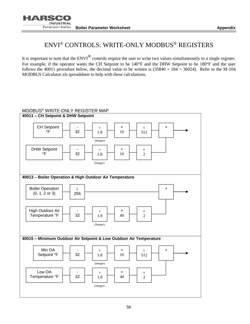
Boiler Parameter Worksheet Appendix
56
ENVI® CONTROLS: WRITE-ONLY MODBUS® REGISTERS
It is important to note that the ENVI®
controls require the user to write two values simultaneously to a single register.
For example, if the operator wants the CH Setpoint to be 140°F and the DHW Setpoint to be 180°F and the user
follows the 40011 procedure below, the decimal value to be written is (35840 + 184 = 36024). Refer to the M-104
MODBUS Calculator.xls spreadsheet to help with these calculations.
MODBUS® WRITE-ONLY REGISTER MAP 40011 – CH Setpoint & DHW Setpoint
40013 – Boiler Operation & High Outdoor Air Temperature
40015 – Minimum Outdoor Air Setpoint & Low Outdoor Air Temperature
CH Setpoint °F
+ 10
- 32
1.8
512
(Integer)
+
DHW Setpoint °F
+ 10
- 32
1.8
2
(Integer)
Min OA Setpoint °F
+ 10
- 32
1.8
512
(Integer)
+
+ 40
- 32
1.8
2
(Integer)
Low OA Temperature °F
256
+
High Outdoor Air Temperature °F
+ 40
- 32
1.8
2
(Integer)
Boiler Operation (0, 1, 2 or 3)

Boiler Parameter Worksheet Appendix
57
40017 – Maximum Outdoor Air Temperature & Outdoor Air Shutdown Temperature
40018 – Outdoor Air Shutdown Temperature & Night Setback
(Integer)
+ 10
- 32
1.8
512
(Integer)
+
+ 40
- 32
1.8
2
OA Shutdown Temperature °F
Max OA Temperature °F
(Integer)
+ 40
- 32
1.8
512
+
1.8
2
OA Shutdown Temperature °F
Night Setback °F
(Integer)


