
1
Equation Sheet
Switched Capacitors
Sum of an infinite geometric series 𝑆𝑘 =𝑎(1−𝑟𝑘)
1−𝑟
Universal Transformer Equation
𝐸𝑟𝑚𝑠 =2𝜋𝑓𝑁𝑎𝐵
√2≈ 4.44𝑓𝑁𝑎𝐵
Buck DC/DC Converter
Boost and Buck-Boost Converters
Thermal voltage across resistor 𝑣𝑛 = √4𝑘𝑇𝐵𝑅, 𝑘 = 1.38 × 10⁻²³
Op-Amps: 𝑉𝑀𝜔 ≤ 𝑆𝑅
Definition of sensitivity 𝑆𝑥𝑦
=𝛿𝑦 𝑦⁄
𝛿𝑥 𝑥⁄=
𝑥
𝑦
𝛿𝑦
𝛿𝑥
𝐋𝐢𝐧𝐞 𝐑𝐞𝐠𝐮𝐥𝐚𝐭𝐢𝐨𝐧 = Δ𝑉𝑜
𝑉𝐼× 100 (%)
Diodes
LS
IOO
if
VVVL
)/1(L
Lo I
C
TItt
CC
QV
82222
11 OFFONIO DVV
IO VD
V
1
1IO V
D
DV
1
i
ooomin
V
VV
L
TI 1
2
ONsattIo
L tL
VVVi
OFF
DoL t
L
VVi
bi
R
j
bi
Rjj
V
V
C
V
VCC
1
10
2/1
0
1
eq
1
CfR
s
21
1
41
2 ESRCESRCCf
RRpump
SWO
LL Ii 2.0
2
2
22
1ESRC
CfIV
pump
ORIPPLE
1T
D
nV
v
SD eIi

2
h-Parameters
2121111 vhihv
2221212 vhihi
0
1
111 2
vi
vh
0
1
221 2
vi
ih 0
2
222 1
iv
ih
BJT CE Version
cerebiebe vhihv
ceoebfec vhihi
ℎ𝑖𝑒 = 𝑟𝑏 + 𝑟𝜋‖𝑟𝜇 ℎ𝑓𝑒 = 𝛽 ℎ𝑟𝑒 ≅𝑟𝜋
𝑟𝜇 ℎ𝑜𝑒 =
1 + 𝛽
𝑟𝜇+
1
𝑟𝑜
y-Parameters
2121111 vyvyi
2221212 vyvyi
0
1
111 2
vv
iy 0
2
112 1
vv
iy
0
1
221 2
vv
iy 0
2
222 1
vv
iy
0
2
112 1
iv
vh

3
RL, RC Series Parallel Transformations
𝑄𝑠 =|𝑋𝑠|
𝑅𝑠, 𝑄𝑃 =
𝑅𝑃
|𝑋𝑃|

4
Fourier Series

5

6
Second-Order Transfer Function Summary
Standard second-order form (s-plane)
𝐻(𝑠) = 𝜔02
𝑁(𝑠)
𝑠2 + 2𝜁𝜔0𝑠 + 𝜔02 =
𝑁(𝑠)
(𝑠
𝜔0)
2
+2𝜁𝜔0
𝑠 + 1= 𝜔0
2𝑁(𝑠)
𝑠2 +𝜔0
𝑄𝑠 + 𝜔0
2
Where 𝑄 = 1 2𝜁⁄ , and 𝐵 = 𝜔0 𝑄⁄ , and 𝜔0 is the undamped natural frequency (rad/s), and 𝜁 (Zeta) is the
damping ratio, and 𝑄 is the quality factor, and 𝐵 is the 3-dB bandwidth in (rad/s)
Case 𝜻 > 𝟏 (Overdamped): The poles are real and negative. The natural response consists of two
decaying exponentials.
Case 𝟎 < 𝜻 < 𝟏 (Underdamped): The poles are complex conjugate 𝑝1,2 = −𝜁ω0 ± 𝑗𝜔0√1 − 𝜁2
The natural response is a damped sinusoid (𝐴 is the residue at the upper pole):
𝑥0(𝑡) = 2|𝐴|𝑒−𝜁𝜔0𝑡 cos (𝜔0√1 − 𝜁2𝑡 + ∡𝐴)
Percentage overshoot (PO) with step response
𝑃𝑂 = 100𝑒−
𝜋𝜁
√1−𝜁2
Case ζ = 0 (No damping): The poles are complex conjugate: 𝑝1,2 = ±𝑗𝜔0. The natural response is a
sustained sinusoid with frequency ω0
Case ζ < 0 (Unstable): The poles lie in the right-hand plane causing a diverging response.

7
Phase-Locked Loop Equations
Phase Detectors
𝐾𝑑 Output With No Input?
XOR 𝑉𝐶𝐶 𝜋⁄ 𝑉𝑐𝑐 2⁄
Charge Pump 𝑉𝐶𝐶 4𝜋⁄ 0
Special Case: First-Order System
𝐻(𝑠) =𝜃𝑜(𝑠)
𝜃𝑖(𝑠)=
𝑇(𝑠)
1 + 𝑇(𝑠)=
𝐾𝑣𝐹(𝑠)
𝑠 + 𝐾𝑣𝐹(𝑠)

8
Special Case: Lag-Lead Filter
𝐻(𝑠) =𝜃𝑜(𝑠)
𝜃𝑖(𝑠)=
(2𝜁 − 𝜔𝑛 𝐾𝑣⁄ )(𝑠 𝜔𝑛⁄ ) + 1
(𝑠 𝜔𝑛⁄ )2 + 2𝜁(𝑠 𝜔𝑛⁄ ) + 1
𝜔𝑛 = √𝜔𝑝𝐾𝑣 𝜁 =𝜔𝑛
2𝜔𝑧(1 +
𝜔𝑧
𝐾𝑣)
𝜔−3dB = 𝜔𝑛 [1 ± 2𝜁2 + √1 + (1 ± 2𝜁2)2]
12
If 𝜔𝑧 = √𝜔𝑝𝐾𝑣 ⇒ 𝜃𝑚 = 45°
If 0.5 ≤ 𝜁 ≤ 1 then 𝜔𝑛 ≅ 1 𝜏⁄
The + sign is for high-gain loops, and the - sign is for low-gain loops. A high-gain loop is when
(𝐾𝑑𝐾𝑜) (𝑅2𝐶) ≫ 1⁄
𝑇(𝑠) = 𝐾𝑣
𝐹(𝑠)
𝑠
𝑇(𝑗𝜔) =1 + 𝑗𝜔 𝜔𝑧⁄
(𝑗𝜔 𝐾𝑣⁄ )(1 + 𝑗𝜔 𝜔𝑝⁄ )
𝐹(𝑠) =1 + 𝑠 𝜔𝑧⁄
1 + 𝑠 𝜔𝑝⁄
𝜔𝑧 = 1 𝑅2𝐶⁄ 𝜔𝑝 = 1 (𝑅1 + 𝑅2)𝐶⁄
𝑅1𝐶 determines settling time. Ratio 𝑅1 𝑅2⁄ determines the
damping ratio. Small values
overshoot, reduce phase margin.
Good place to start is 𝑅1 𝑅2⁄ ≅
0.1— 0.2
9
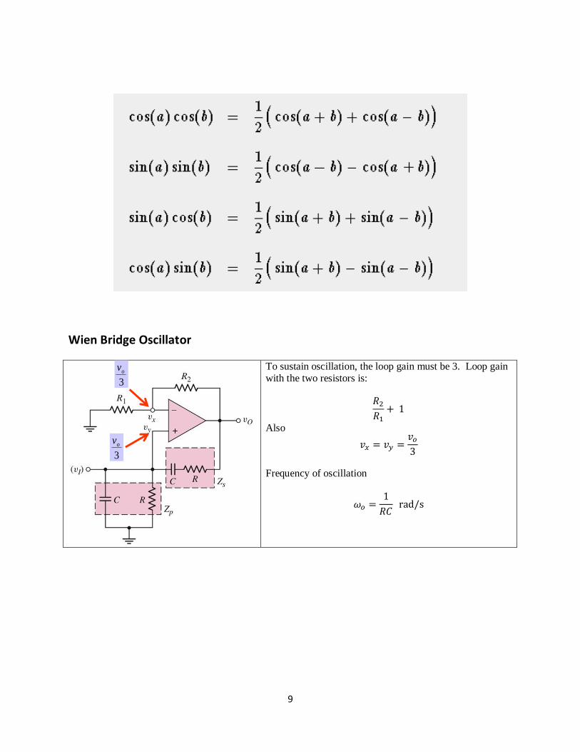
Wien Bridge Oscillator
To sustain oscillation, the loop gain must be 3. Loop gain with the two resistors is:
𝑅2
𝑅1+ 1
Also
𝑣𝑥 = 𝑣𝑦 =𝑣𝑜
3
Frequency of oscillation
𝜔𝑜 =1
𝑅𝐶 rad/s
3
ov
3
ov


