I I I I I I I I I I I I I I I I I I I
EQUIPMENT FOR PERMEABILITY TESTING WITH HAZARDOUS AND TOXIC PERMEANTS
Jeffrey C. Evans1 and Hsai-Yang Fang2
ABSTRACT
The measurement of the permeability of fine-grained soils utilizing hazardous and toxic permeants requires equipment specifically designed and constructed for that purpose. Interaction between the pore fluids in the soils and the resulting soil response must be considered as well as the compatibility between the test equipment and the permeants. Further, a method of modeling the state of stress and permeation relative to field conditions must be incorporated in order to arrive at a system which can adequately determine the effects of hazardous and toxic permeants upon the permeability of fine-grained soils.
The permeability testing system developed for permeability testing with hazardous and toxic permeants has three major components. These are the control panel, the permeability board and the triaxial cell. The necessary strength and compatibility was accomplished through the optimum use of stainless steel and aluminum to provide adecwate rigidity while providing the ultimate compatibility through the use of Teflon at any points in which the permeameter is in contact with the permeant. Equipment design and fabrication considerations in their special applicability for testing of hazardous and toxic permeants are discussed in this paper.
KEYWORDS
1.
2.
Equipment, Testing, Permeability, Hazardous and Toxic Wastes, Soil Mechanics, Geotechnology, Construction, Waste Containment Systems, Clay Minerals
Senior Project Engineer, Woodward-Clyde Consultants, Plymouth Meeting, PA 19462
Professor and Director, Geotechnical Engineering Division, Lehigh University, Bethlehem, PA 18015
I I I I I I I I I I I I I I I I I I I
p. 2
EQUIPMENT FOR PERMEABILITY TESTING WITH HAZARDOUS AND TOXIC
PERMEANTS
INTRODUCTION
Disposal of hazardous and toxic wastes in the subsurface environment
has resulted in the need to adequately assess the permeability of fine-grained soils
with hazardous and toxic permeants (3). The successful application of
geotechnology to the design and construction of waste containment systems hinges
upon our understanding of the pore-fluid soil interactions. Further, our
understanding of pore-fluid clay interactions depends upon the proper use of the
appropriate equipment in the laboratory. The proper design and fabrication of
testing apparati to determine the permeability of soils with hazardous and toxic
permeants is essential to the successful application of geotechnology and the
containment of hazardous and toxic wastes.
The measurement of the permeability of fine-grained soils utilizing
hazardous and toxic permeants requires equipment specifically designed and
constructed for that purpose (1,4). Interaction between the pore fluids and the
soils and the resulting soil response must be considered as well as the compatibility
between the test equipment and the permeants. Further, a method of modeling
state of stress of the soil and the permeation relative to field conditions must be
incorporated into test equipment in order to arrive at a system which can
adequately determine the effects of hazardous and toxic permeants upon the
permeability of fine-grained soils.

I I I I I I I .I
I I I I I I I I I I I
p. 3
It is the purpose of this paper to examine, in detail, the equipment
necessary for determination of the permeability of low-permeability soils with
hazardous and toxic permeants. The equipment developed at Lehigh University (2)
will be described in detail with emphasis on the unique features of this system.
PERMEABILITY TESTING SYSTEM
In order to effectively measure the permeability of soils when
permeated with a wide range of hazardous and toxic wastes, it was necessary to
develop a new permeameter system. This system development was required
because the response of soils to hazardous and toxic wastes can differ significantly
from "normal" permeability testing. The permeability testing system developed for
these studies has three inajor components, the control panel, the permeameter
board, and the triaxial cell. Each of these components are discussed separately in
this chapter. Equipment design and fabrication considerations, and their special
applicability for the testing of hazardous and toxic wastes permeants are included.
Triaxial Cell
The determination of permeability is highly dependent upon the state
of stress on the sample. In order to control the state of stress, the triaxial cell
represents the generally accepted state-of-the-art. This is particularly true with
permeability testing (6). In a triaxial cell, a sample is maintained in a controlled
state of triaxial stress which can be closely model the in situ state of stress.
I I I I I I I I I I I I I I I I I I I
p.4
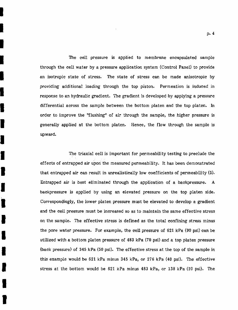
The cell pressure is applied to membrane encapsulated sample
through the cell water by a pressure application system (Control Panel) to provide
an isotropic state of stress. The state of stress can be made anisotropic by
providing additional loading through the top piston. Permeation is induced in
response to an hydraulic gradient. The gradient is developed by applying a pressure
differential across the sample between the bottom platen and the top platen. In
order to improve the "flushing" of air through the sample, the higher pressure is
generally applied at the bottom platen. Hence, the flow through the sample is
upward.
The triaxial cell is important for permeability testing to preclude the
effects of entrapped air upori the measured permeability. It has been demonstrated
that entrapped air can result in unrealistically low coefficients of permeability (5).
Entrapped air is best eliminated through the application of a backpressure. A
backpressure is applied by using an elevated pressure on the top platen side.
Correspondingly, the lower platen pressure must be elevated to develop a gradient
and the cell pressure must be increased so as to maintain the same effective stress
on the sample. The effective stress is defined as the total confining stress minus
the pore water pressure. For example, the cell pressure of 621 kPa (90 psi) can be
utilized with a bottom platen pressure of 483 kPa (70 psi) and a top platen pressure
(back pressure) of 345 kPa (50 psi). The effective stress at the top of the sample in
this example would be 621 kPa minus 345 kPa, or 276 kPa (40 psi). The effective
stress at the bottom would be 621 kPa minus 483 kPa, or 138 kPa (20 psi). The

I I I I I I I I I I I I I I· I I I I I
p. 5
average effective stress would therefore be 207 kPa (30 psi). By regulating top and
bottom pressures, and confining pressure, it is possible to simulate an average in
situ state of stress as well as devel9p appropriate gradients to establish reasonable
test times, and/or simulate field conditions.
Note that the simulation of confining stresses is not possible in a
fixed wall permeameter. With this type of equipment, the permeameter walls are
rigid, and the state of stress is both uncontrolled and unknown.
Another important advantage of the triaxial cell in permeability
testing relates to the potential for bulk transport of fluids between the sample and
the equipment. In a triaxial cell permeameter, the sample is maintained
encapsulated in a flexible membrane. Conversely, in a fixed-wall permeameter,
there is a sample-permeameter wall interface. The wall is rigid and cannot move.
Therefore, if the sample shrinks, bulk transport of fluids at the interface of the
sample and permeameter wall can result. Should sample shrinking occur while
testing in a triB:xial cell, the membrane is simply maintained against the sample
because of the confining stress maintained on the sample. Further, shrinking or
swelling of the sample in the triaxial cell does not change the state of stress. In a
fixed wall permeameter, as the sample shrinks, the confining stress is reduced.
Conversely, as the sample swells, the confining stress is increased. This aspect is
very important, since certain clayey soils may be initially consolidating due to the
effect of hazardous and toxic pore fluids upon the sample. In a fixed-walled
permeameter, at the point that the sample shrinks enough to develop a void space

I I I I I I I I I I I I I I I I I I I
p. 6
between the sample and the permeameter wall, an open channel is available for
bulk transport of permeant. This results in large increases in the calculated value
of permeability. From the data obtained utilizing a fixed wall permeameter,
therefore, it is difficult to assess the actual effect of pore fluid upon the soil due
to masking by the bulk transport mechanisms.
Having thus established the need to utilize triaxial cells for
permeability testing, the unique features of the triaxial cells developed at Lehigh
University (2) for these studies require further elucidation. As stated, one of the
more significant laboratory difficulties which must be overcome for the
determination of permeability with hazardous and toxic permeants, is the
compatibility between the testing equipment and the permeant. For example, a
typical triaxial cell is constructed of aluminum. Aluminum exposed to even
relatively dilute concentrations of acids or bases, will tend to corrode and dissolve.
A triaxial cell material for a study such as this must therefore be compatible with
a wide range of permeants in order to be functional. The logical choice is the use
of TeflonR for the ultimate in hazardous and toxic permeant and equipment
compatibility. TeflonR, however, is extremely flexible. Therefore, TeflonR
cannot typically maintain the high pressures required to provide back pressure
saturation and an adequate effective stress. The structural rigidity of aluminum or
steel is therefore necessary to provide rigidity to the triaxial equipment. This
dichotomy of goals was satisfied through the specially designed and fabricated
triaxial cells shown schematically in Fig. 1. These cells optimize the use of
stainless steel and aluminum to provide adequate rigidity, but they provide the

I I I I I I I I I I I I I I I I I I I
p. 7
TO CELL PRESSURE CONTROL ~ AXIAL LOAD"\ r LOADING RAM
CHECK VALVE ~ ;±t. /._~ THOMPSON BEARINGS ~l ,_ ~~ e
r------1 - ~---,_ r-- ALUM I HUM TOP
0-RING
TEFLON® -'- -
TOP CAP --+--I-...._.._ f-.
~ ---\..)- ~ I-- PLEX I GLASS® 1 : CYLINDER liv~~~ztiz~s~~tL_l_l_ r INSET POROUS STONE
~ SAMPLE
~-..........__.__ TEFLON ® TUBE
MEMBRANE ENCLOSED SAMPLE
TEFLON® , PEDESTAL -t--+--.LI - INSET POROUS STONE
f-:..1r fiT. 7 . I I I ,t..r, tA-~-1---+---
-- DOUBLE 0-RINGS ~ ~ f-!r.:::: ~ 1-
-~STAINLESS STEEL BASE
'---1 ~--- r----1 '"'--1 1---....1
CONTROL FOR ORA 1 MAGE~ OR PRESSURE CONTROL ~
FIGURE I LEHIGH TRIAXIAL CELL SCHEMATIC

I I I I I I I I I I I I I I I I I I I
p. 8
ultimate in compatibility through the use of TeflonR at any points in which the
permeameter is in contact with the permeant.
Details for the Lehigh triaxial cells are shown on Figs. 2, 3, 4 and 5.
The base is constructed of 316 stainless steel. The pedestals and associated tubing
are all of TeflonR. Special fittings were designed and constructed to allow passage
of the tubing and permeant through the stainless steel base while within the
TeflonR tubing. Special design requirements had to be met to insure no leakage of
cell pressure in the areas where the tubing passes through the base. All 0-rings are
of chemically resistent Viton.
In addition to the advances in permeant-equipment compatibility, the
triaxial cell developed for this testing includes the ability to flush all the air from
the platens and porous stones through the use of a double-line drainage system
feeding each of the two platens (see Figs. 2 and 3). In addition, friction is
minimized during the loading of the sample through the use of Thompson bearings
placed in the aluminum caps of the triaxial cell. These bushings, with a minimum
friction, minimize the leakage that would occur in friction seals that do not make
the use of bearings. Finally, several additional ports are provided in order to
permit other types of monitoring which may be required with these cells. This
would include the installation of pore pressure transducers, as well as monitoring of
changes in cell water volume due to shrinking or swelling of the sample or, leakage,
or osmotic diffusion of permeants through the membrane.

-----~--~-~~-------
POROUS STONE
TEFlON® TUBE SWAGElOK ®FITTING
FIGURE 2 lEHIGH TRIAXIAl CEll DETAilS .
'"0 .

I I I I I I I I I I' I I I I I I I I I
p. 10
"0" RING.
I TOP PLATIEN
/I TEFLON(] TUBE
FIGURE 3 LEHIGH TRIAXIAL CELL DETAILS

I I I I I I I 'I I I I I I I I I I I I
: FIGURE~ LEHIGH TRIAXIAL CELL PHOTOGRAPH
p. 11
.... :-.-··- /.·--.
. __ __,

I I I I I I I I I I I I I I I I I I I
FIGURE 5 LEHIGH TRIAXIAL CELL PHOTOGRAPH
p. 12

I I I I I I I I I I I I I I I I I I I
p. 13
Permeability Board
A permeability board was designed, constructed, and tested in order
to fully satisfy the objectives and constraints required to monitor the permeation
of soils with hazardous and toxic permeants. This board, shown schematically in
Fig. 6, has several unique features. The ability to measure both inflow and outflow
volumes has been incorporated into the permeability board design. Readings are
taken on an inflow riser pipe as well as an outflow riser pipe. In this way, volume
changes in the sample, apparatus leaks, or permeant diffusion can be evaluated by
notice the differences between readings in the inflow and outflow riser pipes. In
addition, the permeability board is designed to allow permeants to be changed and
the inflow riser pipes either filled or emptied without changing the state of stress
on the sample. This is an important aspect of the system design. In order to
maintain the proper experimental accuracy, it is necessary to read small changes in
the volume of_permeant that penetrates this sample. However, to read these small
changes, the inflow and outflow riser pipes are quickly emptied and filled,
respectively. Hence, it is necessary to refill the inflow riser pipe and empty the
outflow riser pipe frequently throughout the testing period. In order to preclude
sample changes that may occur due to repeated changes of stress on the sample, it
was necessary to enable the permeameter board to be "rezeroed" without changing
the state of stress on the sample. This was done by means of incorporating influent
and effluent reservoirs into the pressure system as shown in detail on Fig. 6. For
example, the inflow reservoir can be pressurized to the same background pressure
as the inflow riser pipe. Then because of the additional gravimetric head provided

I I I I I I I I I I I I I I I I I I I
p. 14
TO AIR PRESSURE REGULATOR, crBOTTOM
INFLUENT RESERV.O I R
INFLUENT
CDi® TO AIR PRESSURE REGULATOR, crTOP
® 0
r----++-- METER STICK
RISER TUBE-++--~ EFFLUENT ,..,_,t----++- R I SER TUBE
LEGEND: VALVE
CD ® G) ® ® ® <D ® ® @ ([J)
@
VALVE NAME/FUNCTION -MATERIAL
INFLUENT RESERVOIR PRESSURE CONTROL VALVE- BRASS INFLUENT RISER TUBE PRESSURE CONTROL VALVE- BRASS INFLUENT RISER TUBE FILL VALVE- TEFLONGD INFLUENT RISER TUBE BY-PASS VALVE- TEFLONCD INFLUENT RESERVOIR DRAIN VALVE - TEFLONQD
EFFLUENT RESERVOIR
INFLUENT RESERVOIR PRESSURE RELIEF VALVE (THREE-WAY) -BRASS EFFLUENT RESERVOIR PRESSURE CONTROL VALVE - BRASS EFFLUENT RISER TUBE PRESSURE CONTROL VALVE - BRASS EFFLUENT RISER TUBE DRAIN VALVE - TEFLOHQD EFFLUENT RISER TUBE BY-PASS VALVE- TEFLQNQD
EFFLUENT RESERVOIR DRAIN VALVE - TEFLONCD
FIGURE 6 LEHIGH CONTROL PANEL.SCHEMATIC

I I I I I I I I I I I I I I I I I I I
p. 15
by the influent reservoir, the influent fill valve can be opened allowing a gravity
refilling of the inflow reservoir. The system is reversed for draining of the
effluent riser pipe.
The permeability board was designed to accommodate the wide range
of stresses required for permeability testing. As shown on Fig. 6, this system has
been developed to accommodate stresses up to a maximum of 897 kPa (130 psi).
This is necessary in order to be able to model a wide range of stresses that could
potentially be encountered in the field and to permit adequate backpressure to
insure saturation.
In addition to the functional criteria that were incorporated in the
design of the permeability· board shown on Fig. 6, the question of permeant
equipment compatibility was again addressed. Essentially all valves, fittings, and
tubings shown on Fig. 6 which come in contact with the permeant are constructed
of TeflonR. Valves which simply control air pressures to modify stresses and do
not come in contact with the permeant are typically constructed of brass or
stainless steel. A photograph of the board is shown in Fig. 7.
Control Panel
The control panel developed to conduct permeability tests with
hazardous and toxic permeants is shown in Fig. 8. The functional criteria of the
control panel design included the necessity to control the back pressure, gradient,

I I I I I I I I I I I I I I I I I I I
~t IH
FIGURE 7 LEHIGH PERMEABILITY BOARD PHOTOGRAPH
p. 16

I I I I I I I I I I I I I I I I I I I
p. 17
CEL.L PLATENS TEST GAUGE
MO I STURE TRAP
L-.~..;.;.;....:..::::.:.;;.;.;~--E--_....r- VACUUM
CEL.L ORAl N
® Z-WAY VALVE
@ 3-WAY VALVE
0 REGULATOR
t
FIGURE 8 LEHIGH CONTROL BOARD SCHEMATIC
SUPPLY

I I I I I I I I I I I I I I I I I I I
p. 18
and confining stress to maintain the effective stress conditions. Further, the
control panel must permit refilling of reservoirs at the beginning and during the
test. Shown on Fig. 8 is a detailed schematic of the control panel and on Fig. 9, a
photograph of the control panel. The uniqueness of the control panel is limited to
its functional ability to supply the appropriate pressures to the permeability board.
Additional Equipment
In addition to the triaxial cell permeability board and control panel,
certain additional equipment is necessary to conduct the permeability tests. Of
primary importance is the triaxial cell membrane used to encapsulate the sample.
Three materials are presently available for membrane materials. These are
neoprene, butyl rubber arid latex. Membranes of all three types were purchased for
this research and a compatibility chart was checked prior to permeation with the
selected pore fluid to insure compatibility between the membrane selected and the
pore fluid to be utilized.
Each of the triaxial cells have the porous stone seated in both the top
and bottom platens. These porous stones were obtained from a soil testing
equipment vendor and consists of 6.4 mm (1/4-inch) thick, 63.5 mm (2.5 inch)
diameter, carborundum stones.
In order to fabricate samples in the laboratory of the specified
dimensions, sample molds were required. These were custom designed and

I I I I I I I I I I I I I I I I I I I
FIGURE 9 LEHIGH CONTROL PANEL PHOTOGRAPH
p. 19

I I I I I I I I I I I I I I I I I I I
p. 20
fabricated of aluminum in order to be utilized with the triaxial cell TeflonsR and
platens. Although the concept of split-ring sample molds is not unique, it was
necessary to fabricate these molds in order to insure the proper dimensions
consistent with the triaxial equipment utilized for these studies.
TYPICAL RESULTS
Shown on Fig. 10 are the results of the typical triaxial cell
permeability tests where the effect of acetic acid upon the permeability of a soil
bentonite mixture was investigated. Note that· after the initial application,
saturation and permeation with water, the system achieved equilibrium and, at that
point in time, acetic acid permeant was added. Permeability in response to the
acetic acid permeant was monitored for a total pore volume displacement of
approximately 8. As a gradual increase in permeability resulting from changes in
the double layer as well as dissolutioning of the mineralogical ~tructure.
Additional details regarding procedure and analysis of specific permeability test
results are contained in Reference 2. Utilizing the same equipment, the stress
strain relationship was developed after permeation for this sample as shown in Fig.
11.
SUMMARY AND CONCLUSIONS
Permeability testing equipment was designed and constructed to
conduct triaxial permeability tests with a wide range of chemical permeants.

-------------------
_J·
POOE Vfl...lH DlsrL.ACEHEHT (PVO)
0.00 1.00 2.00 3.00 4.00 5.00 6.00 1.00 8.00 •o-6 .----...--,---.,..--.------..r-r----w----r---.--.---.--,--r---.---....-,--.,
-·JE..._J__._ ACEJIC ACID
. .. I
I . I . . . . . .... . . .
•• •• • ••• • • ... .. . . I I I
. .., ..... • • • • • • .. . . .
.. .. . . . . .
IQ-8 1------1-t------+-~-----1---------+------1 I I I I I
•o-9 L.... ___ __JIL_...~_ _____ _J_~__.:;_··----L-----___._ _____ __.
0 20,000 40,000 60,000 80,000 100,000
ELAPSED TIHE (•inutes)
49
GRADIENT (in/In)
FIGURE 10 PERMEABILITY TEST RESULTS - SAMPLE HUMBER S-16
N ,.....

p. 22
I I I I I
200
I I t1S
c::l.. ::.;
150
a
I -.; -
I 'v -. ~ 100
I (,j z ~ IX ~
""' ""' I Q
en en ~ IX
I 1-en 50
I I 0
0 0.8 1.6 2."' 3.2 "'·0 I AXIAL STRAIN, %
I FIGURE I I STRESS-STRAIN RELATIONSHIP - SAMPLE NUMBER S-15
I I I

I I I I I I I I I I I I I I I I I I I
p. 23
Based upon the equipment development work and the results of numerous
permeability tests conducted utilizing this equipment, it is concluded that the
triaxial cell permeability equipment can be successfully utilized to examine the
influence of hazardous and toxic permeants upon the permeability of fine-grained
soils.
ACKNOWLEDGEMENTS
The financial support for these studies was provided by Woodward
Clyde Consultants, Plymouth Meeting, Pennsylvania, Mr. FrankS. Waller, Managing
Principal and the by Center for Marine and Environmental Sciences, Mr. Irwin J.
Kugelman, Director. This support is gratefully acknowledged. Technical
discussions with Mr. Enrique Manuel and Mr. Jerry Schexnayder were beneficial to
this project. Triaxial cells were fabricated by J. V. Machine Corporation. Typing
was provided by Gail M. Bertsch.

I I I I I I I I I I I I I I· I I I I II
p. 24
REFERENCES
(1) Evans, J. C., Kugelman, I. J. and Fang, H. Y. (1983), "Influence of Industrial Wastes on the Geotechnical Properties of Soils", Toxic and Hazardous Waste, Butterworth Publishing, Boston, p. 557-568.
(2) Evans, J. C. (1984), "Permeant Influence on the Geotechnical Properties of Soils", a Dissertation for the Degree of Doctor of Philosophy, Civil Engineering Department, Lehigh University, Bethlehem, PA, 18015.
(3) Fang, H. Y., Evans, J. C. and Kugelman, I. J. (1984), "Solid and Liquid Waste Control Techniques", Solid and Liquid Wastes, Management and Methods, Chapter 10, edited by Majundary and Miller, Pennsylvania Academy of Science Press, p. 245-265.
(4) Fang, H. Y., Evans, J. C. and Kugelman, I. J. (1984), "Effect of Pore Fluid on Soil Cracking Mechanism", Proc. ASCE Engineering Mechanics Specialty Conference, University of Wyoming, Vol. 2, p. 1292-1295.
(5) Olson, R. E. and Daniel, D. E. (1981), i'Measurement of Hydraulic Conductivity of Fine-Grained Soils", ASTM STP 746, p. 18-64.
(6) Zimmie, T. F., Doynow, J. S. and Wardell, J. T. (1981), "Permeability Testing of Soils for Hazardous -Waste Disposal Sites", Proc. 5th ICSMFE, Stockholm, p. 403-408. .


