
1
ESD.33 -- Systems Engineering
Session #4 Requirements Engineering
Pat Hale

As stated in ISO/IEC 15288:2008: The purpose of the Stakeholder Requirements Definition Process is to define the requirements for a system that can provide the services needed by users and other stakeholders in a defined environment. It identifies stakeholders, or stakeholder classes, involved with the system throughout its life cycle, and their needs, expectations, and desires. It analyzes and transforms these into a common set of stakeholder requirements that express the intended interaction the system will have with its operational environment and that are the reference against which each resulting operational service is validated
Purpose
2
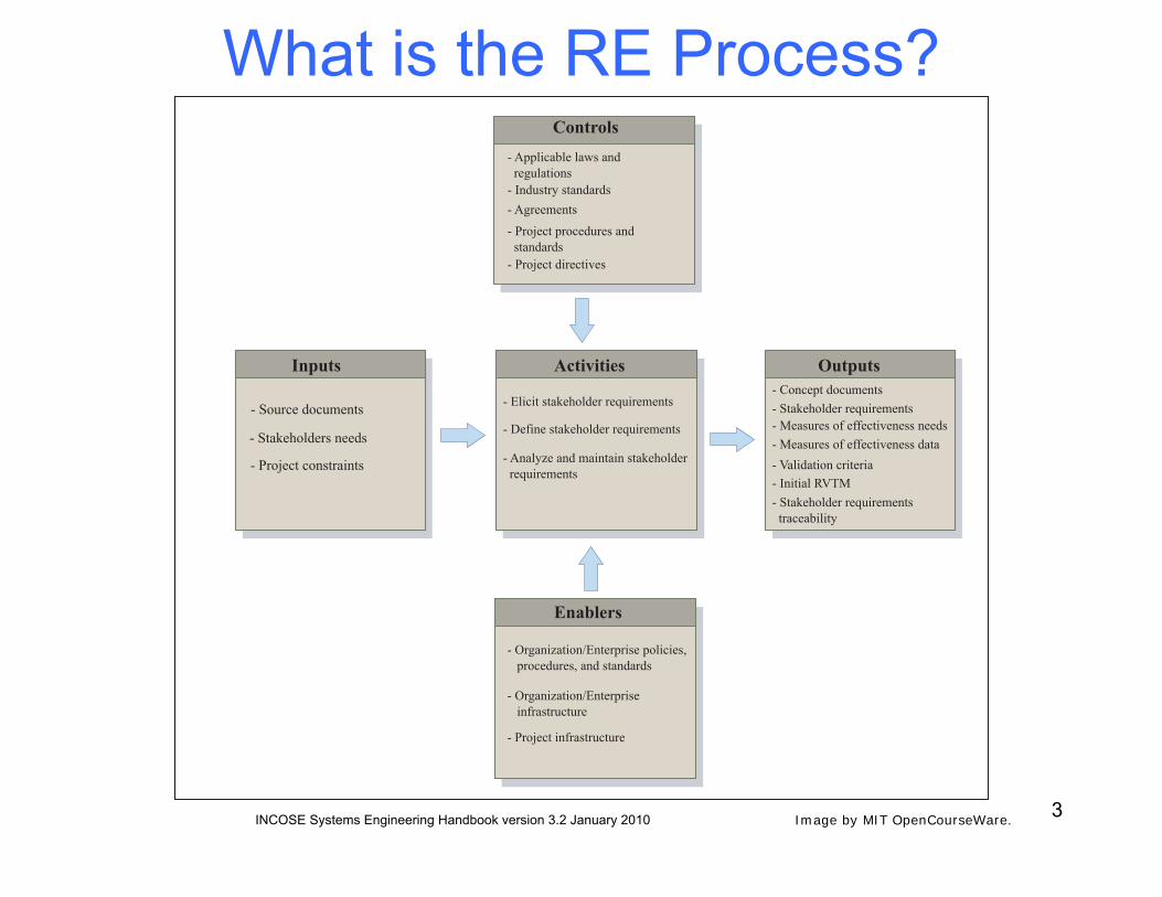
What is the RE Process?
3 INCOSE Systems Engineering Handbook version 3.2 January 2010
Inputs
- Source documents
- Stakeholders needs
- Project constraints
Activities
- Elicit stakeholder requirements
- Define stakeholder requirements
- Analyze and maintain stakeholder requirements
Enablers
- Organization/Enterprise policies, procedures, and standards
- Organization/Enterprise infrastructure
- Project infrastructure
- Concept documents- Stakeholder requirements- Measures of effectiveness needs- Measures of effectiveness data- Validation criteria- Initial RVTM- Stakeholder requirements traceability
Outputs
Controls- Applicable laws and regulations- Industry standards- Agreements
- Project procedures and standards- Project directives
Image by MIT OpenCourseWare.

4
Why ‘Engineer’ Requirements?
• Provide early assurance that all top-level requirements are fully satisfied in the product, with traceability to where they are satisfied.
• Prevent unintentional addition of cost (avoid ‘gold plating’). • Establish clear responsibility for requirements
implementation. • Provide clear visibility across teams into requirements
allocation and cross-functional interactions. • Easily and quickly assess the impact of changes to
requirements. • Provide data for early and thorough validation and
verification of requirements and design artifacts. • Avoid unpleasant downstream surprises!

5
Requirements Management
• System/Product needs are captured from the market, business strategy, customers and other sources.
• Requirements are synthesized from captured needs and the meanings and interpretations are validated with the original sources.
• Commitment to requirements is obtained from management and project personnel.
• A history of changes and change rationale is maintained as requirements evolve.
• Bi-directional traceability is maintained among requirements, project plans and work products.
• Inconsistencies are identified and resolved among requirements, project plans and work products.
Requirements Management is the process by which:
6
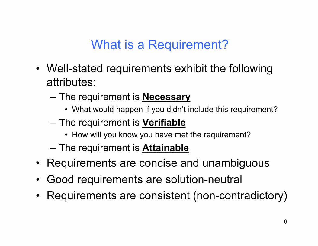
What is a Requirement?
• Well-stated requirements exhibit the following attributes: – The requirement is Necessary
• What would happen if you didn’t include this requirement?
– The requirement is Verifiable • How will you know you have met the requirement?
– The requirement is Attainable • Requirements are concise and unambiguous • Good requirements are solution-neutral • Requirements are consistent (non-contradictory)

7
Requirements Semantics
• Requirements use ‘shall’ – The system shall provide… – The system shall be capable of… – The system shall weigh…
• Statements of fact use ‘will’ – Often part of a lead-in scenario prefacing one or more
requirements • Goals use ‘should’
– Used for design goals where quantifiable requirements cannot be applied to a desired attribute
8
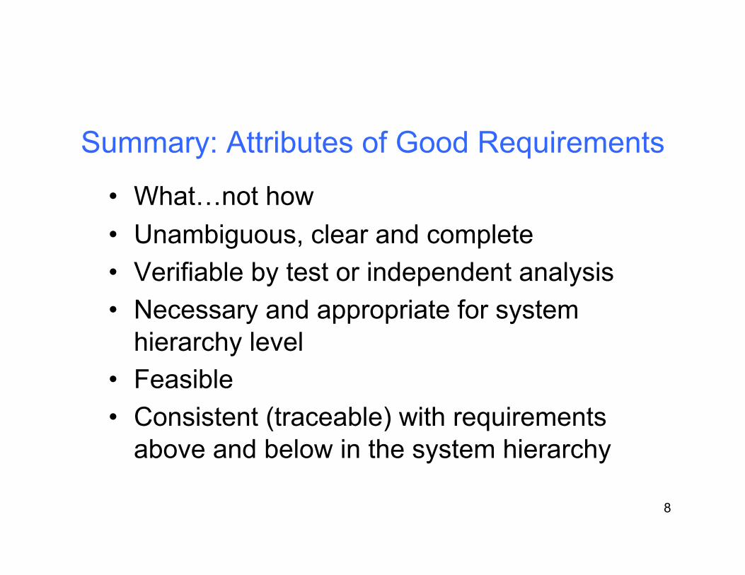
Summary: Attributes of Good Requirements
• What…not how • Unambiguous, clear and complete • Verifiable by test or independent analysis • Necessary and appropriate for system
hierarchy level • Feasible • Consistent (traceable) with requirements
above and below in the system hierarchy

Requirements Baselines
9
INCOSE Systems Engineering Handbook version 3.2 January 2010
Image by MIT OpenCourseWare.

10
Concept Design Optimize Sub-
Systems
Optimize System
Verify Product Design
Verify Production
Process
Product Commercialization Phases 1-6:
Requirements Baselines in CDOV
VOC 6 4 3 2 1 5
1- Initial baseline 4- Allocated baseline (PAS) 2- Validated baseline (Contract) 5- Component baseline 3- System functional baseline (PFS) 6- Verified product baseline
FRS
11
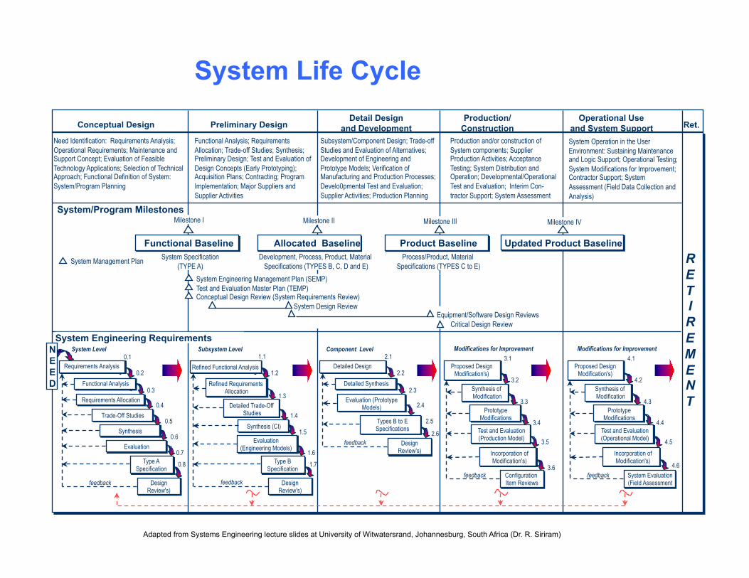
System Life Cycle
Conceptual Design Preliminary Design Detail Design
and Development Production/
Construction Operational Use
and System Support Ret.
Need Identification: Requirements Analysis; Operational Requirements; Maintenance and Support Concept; Evaluation of Feasible Technology Applications; Selection of Technical Approach; Functional Definition of System: System/Program Planning
Functional Analysis; Requirements Allocation; Trade-off Studies; Synthesis; Preliminary Design; Test and Evaluation of Design Concepts (Early Prototyping); Acquisition Plans; Contracting; Program Implementation; Major Suppliers and Supplier Activities
Subsystem/Component Design; Trade-off Studies and Evaluation of Alternatives; Development of Engineering and Prototype Models; Verification of Manufacturing and Production Processes; Develo0pmental Test and Evaluation; Supplier Activities; Production Planning
Production and/or construction of System components; Supplier Production Activities; Acceptance Testing; System Distribution and Operation; Developmental/Operational Test and Evaluation; Interim Con- tractor Support; System Assessment
System Operation in the User Environment: Sustaining Maintenance and Logic Support; Operational Testing; System Modifications for Improvement; Contractor Support; System Assessment (Field Data Collection and Analysis)
System/Program Milestones Milestone I
Functional Baseline
Milestone II
Allocated Baseline
Milestone III
Product Baseline
Milestone IV
Updated Product Baseline System Specification
(TYPE A) Development, Process, Product, Material
Specifications (TYPES B, C, D and E) Process/Product, Material
Specifications (TYPES C to E) System Management Plan
System Engineering Management Plan (SEMP) Test and Evaluation Master Plan (TEMP) Conceptual Design Review (System Requirements Review)
System Design Review Equipment/Software Design Reviews Critical Design Review
System Engineering Requirements
Requirements Analysis
Functional Analysis
N E E D
Requirements Allocation
Trade-Off Studies
Synthesis
Evaluation
Type A Specification
Design Review's)
System Level 0.1
0.2
0.3
0.4
0.5
0.6
0.7
0.8
Refined Functional Analysis
Refined Requirements Allocation
Detailed Trade-Off Studies
Synthesis (CI)
Evaluation (Engineering Models)
Type B Specification
Design Review's)
Subsystem Level 1.1
1.2
1.3
1.4
1.5
1.6
1.7
Detailed Design
Detailed Synthesis
Evaluation (Prototype Models)
Types B to E Specifications
Design Review's)
Component Level 2.1
2.2
2.3
2.4
2.5
2.6
Proposed Design Modification's)
Synthesis of Modification
Prototype Modifications
Test and Evaluation (Production Model)
Configuration Item Reviews
3.1
3.2
3.3
3.4
3.5
3.6
R E T I R E M E N T
feedback feedback
Modifications for Improvement
Incorporation of Modification's)
Proposed Design Modification's)
Synthesis of Modification
Prototype Modifications
Test and Evaluation (Operational Model)
System Evaluation (Field Assessment
4.1
4.2
4.3
4.4
4.5
4.6
Modifications for Improvement
Incorporation of Modification's)
feedback
feedback feedback
Adapted from Systems Engineering lecture slides at University of Witwatersrand, Johannesburg, South Africa (Dr. R. Siriram)

12
Requirements Hierarchy & Traceability
Source Needs
Critical Issue
Decision
documents
satisfied by
allocated to
generates
traces to
traces to
incorporates
incorporates
Originating Requirement
Function
Subsystem
decomposed from
Validation Requirement
Test Method & Criteria
Assembly
built from
Component built from
integrates to
VOC
Contract
Requirements Analysis &
Concept Trades
PFS
Subsystem & Component
Design
System Functional Design
Detailed Design
ANALYSIS CYCLE
Allocation
PAS
Level 4 : : integrates to
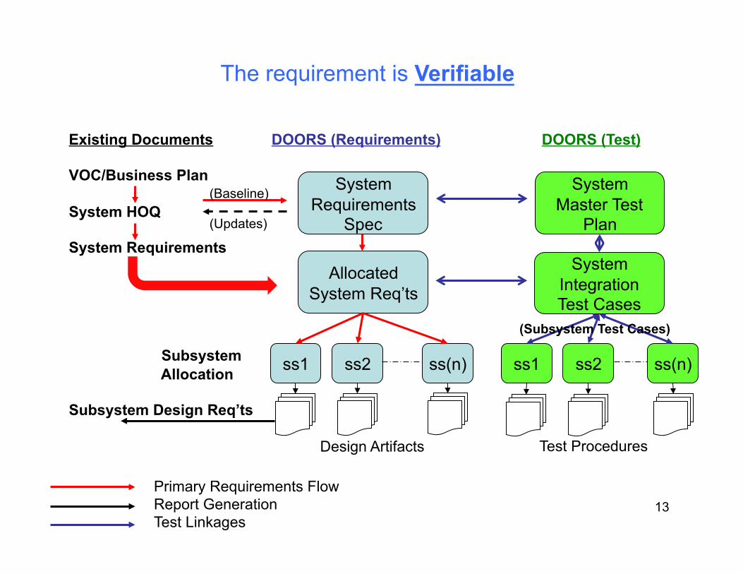
Existing Documents DOORS (Requirements) DOORS (Test)
VOC/Business Plan
System HOQ
System Requirements
Subsystem Allocation
Subsystem Design Req’ts
System Requirements
Spec
System Master Test
Plan
Allocated System Req’ts
ss1 ss2 ss(n) ss1 ss2 ss(n)
Primary Requirements Flow Report Generation Test Linkages
Design Artifacts Test Procedures
System Integration Test Cases
(Subsystem Test Cases)
(Updates)
(Baseline)
The requirement is Verifiable
13

14
Requirements Change Authority VOC
Contract
Requirements Analysis &
Concept Trades
PFS
Subsystem & Component
Design
System Functional Design
Allocation
PAS
Level 4 :
Detailed Component/Part Specifications
Pre-PAS: - Changes/new requirements proposed by any development team member - Review by Systems team and other Stakeholders (e.g. PMT members) as required - Approval by Systems team/Chief Systems Engineer
Post-PAS: - Changes/new requirements proposed by any development team member - Review by Subsystem team with appropriate representation from other affected teams - Decision by Subsystem team leader with primary design responsibility - Weekly review of changes and change proposals by Systems team
Baseline

15
JW, Cons. LD
JW, SS, Cons.
JC
JW, SS, KH, Cons.
JW, DD, Mkt, Test
NGD Team
Implementation Plan
• Propose Draft RM process • Select DOORS versions, obtain
training • Develop requirements schema for
RM & CPM (link, no common schema)
• Review and Approve Change Review Process
• Review/Import existing requirements, refine to meet RM criteria
• Certify PFS baseline in DOORS
• Full process implementation
• 10/31/2003 • 11/3/2003
• 11/12/2003
• 11/17/2003
• 12/28/2003
• 1/10/2004
• 1Q04
Task Description Who?1 Target Date

System-level Implementation (Example from a backup tape drive project)
16

17
Documents to DOORS Modules
Baseline PAS
Assign Attributes
WordRich Text(.rtf)
Framemaker
Create Link Module
PFS PAS
Edit, Prepare for Export
Export & CreateDoors Module
Image by MIT OpenCourseWare.
18
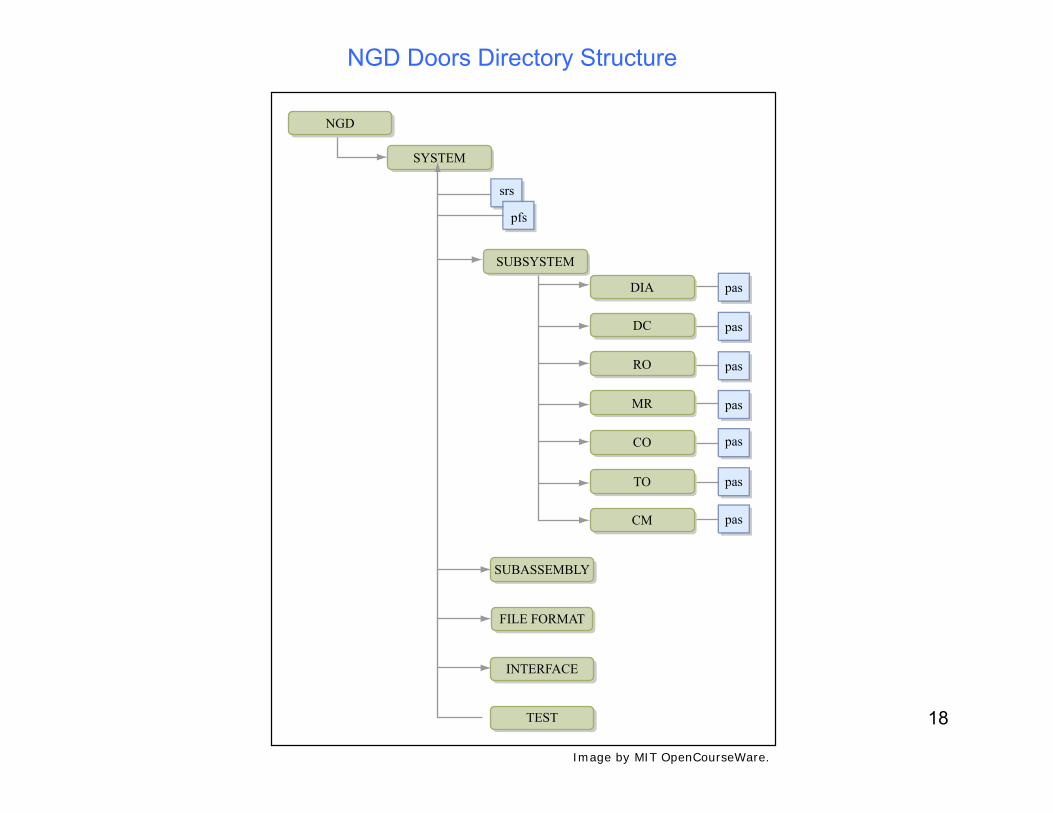
NGD Doors Directory Structure
srs
NGD
SYSTEM
SUBSYSTEM
DIA
DC
RO
MR
CO
TO
CM
SUBASSEMBLY
FILE FORMAT
INTERFACE
TEST
pfs
pas
pas
pas
pas
pas
pas
pas
Image by MIT OpenCourseWare.

19
Formatting PAS in Word for Export into Doors
Keep heading styles in the following form: Heading 1, Heading 2, Heading 3, …,etc.
Notes: – Framemaker documents use Sec-#, Sec-#.#,
Sec-#.#.#. Export Framemaker documents to Word and convert them to Heading 1, Heading 2, etc. before exporting into Doors.
– Keep all other styles consistent throughout (e.g. figure heading, table heading, etc.)

24
Phased Process Outputs
Decision support dataSystem architectureSpecificationBaselines
Synthesis
Transform architecture (Functional tophysical)Define configuration items & elementsDefine/refine physical interfacesSelect preferred product/process solutions
Functional Analysis/ Allocation
Decompose functional requirementsAllocate functionality and performanceto lower levelsDefine/refine functional interfaces andarchitecture
Requirements Analysis
Analyze markets and environmentsIdentify functional/requirementsDefine/refine performance requirementsIdentify constraint requirements
Process Inputs
Business objectivesMarket/competitive requirementsCustomer needs/objectivesTechnology baseEnvironmentsConstraintsSpecifications, codes, standardsProgram decision requirementsMeasures of effectiveness
Modelling, Analysis SimulationDesign for (x)Trade studies/Trade offsRisk managementConfiguration & Data managementInterface managementWork breakdownCritical parameter management (CPM)Technical reviewsLessons learned
SystemAnalysis
& Control(Balance)
Design Loop
Requirements Loop
RequirementsManagementSub-process
Region
Illustrationof a SingleIteration
The System Engineering Process
Verif
icat
ion
Loop
Image by MIT OpenCourseWare.

Another View of the ‘V’ Model
25
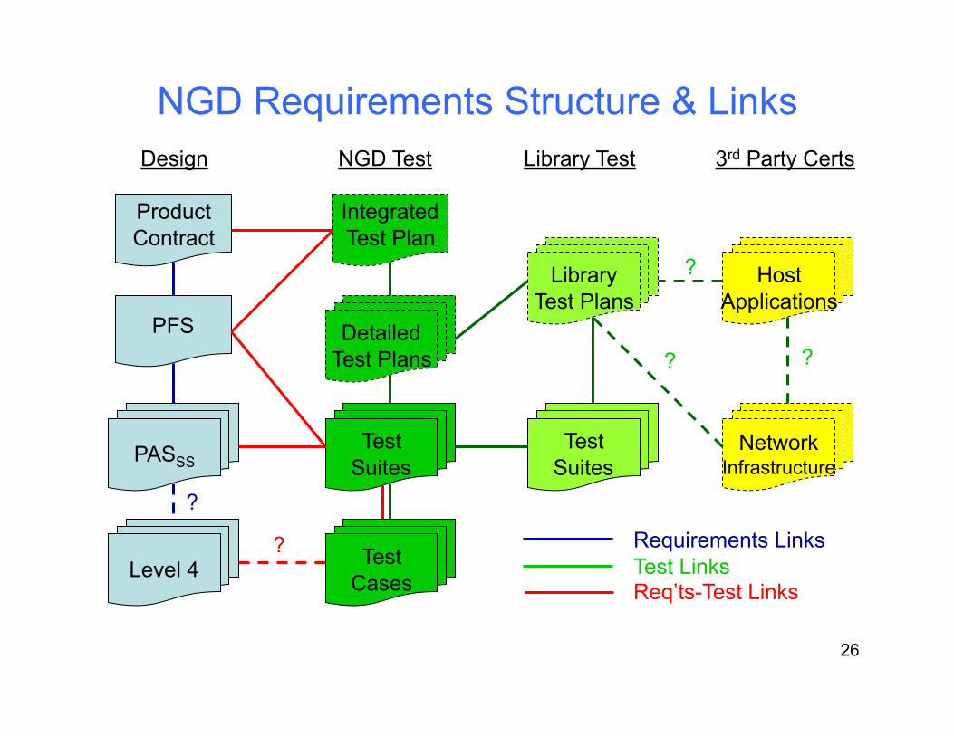
NGD Requirements Structure & Links
Product Contract
PFS
PASSS
Level 4
Integrated Test Plan
Detailed Test Plans
Test Suites
Test Cases
Library Test Plans
Test Suites
Host Applications
Network Infrastructure
Design NGD Test Library Test 3rd Party Certs
?
?
? ?
?
Requirements Links Test Links Req’ts-Test Links
26

Module Schema
27

MIT OpenCourseWarehttp://ocw.mit.edu
ESD.33 Systems EngineeringSummer 2010
For information about citing these materials or our Terms of Use, visit: http://ocw.mit.edu/terms.


