1
ESFR "PRE-PRIMED SINGLE INTERLOCKED
PREACTION" COLD STORAGE SYSTEM
MANUAL
The Viking Corporation 210 N Industrial Park Road
Hastings MI 49058 Telephone: 269-945-9501
Technical Services: 877-384-5464 Fax: 269-945-9599
December 6, 2005F_120805
2
Table of Contents 1.0 System Description ............................................................................................... 7
2.0 ESFR Sprinkler Description .................................................................................. 9
2.1 Storage Arrangements ................................................................................. 9
2.2 Commodity Classification ............................................................................. 9
2.3 Maximum Storage/Ceiling Heights ............................................................... 9
3.0 System Design ...................................................................................................... 9
3.1 Hydraulic Calculations.................................................................................. 9
3.2 Hydraulic Calculation Procedure ................................................................ 11
4.0 Pre-Primed Single Interlocked Preaction System for Cold Storage ................... 11
5.0 System Installation Considerations ..................................................................... 12
5.1 Tree Configuration...................................................................................... 12
5.1.1 Piping System to Sprinklers............................................................ 14
5.1.1.1 General Piping and Material Recommendation ............... 15
5.1.2 Primary Check Valve Main Drain.................................................... 16
5.1.3 Reclaim Tank.................................................................................. 17
5.1.4 Automatic Pressure Control System............................................... 17
5.1.5 Solution Test Valves....................................................................... 18
5.1.6 Re-charging System Piping ............................................................ 19
5.1.7 Expansion of Antifreeze.................................................................. 19
5.1.8 CS-1 Pump ..................................................................................... 20
5.1.9 Propylene Glycol and Water Solution Premix................................. 22
5.1.10 Riser System .................................................................................. 22
5.1.11 Alarm Test Connection ................................................................... 23
5.1.12 Flow Test Valve .............................................................................. 23
5.2 Service Procedures ...................................................................................... 24
5.3 Taking the System out of Service.................................................................. 25
5.4 Placing System in Service............................................................................. 25
6.0 Automatic Pressure Control ................................................................................ 25
6.1 Description ................................................................................................. 25
6.2 Application.................................................................................................. 26
6.3 System Control Switch ............................................................................... 27
6.4 Wiring Diagram........................................................................................... 28
3
6.5 Pressure Switch Set-up.............................................................................. 28
7.0 CS-1 Antifreeze Pump System ........................................................................... 29
7.1 Description ................................................................................................. 29
7.2 Operating Principle..................................................................................... 30
7.3 CS-1 Control Scheme ................................................................................ 32
7.3.1 General........................................................................................... 32
7.3.2 Operation........................................................................................ 32
7.3.3 Solenoid Valve Operation............................................................... 32
7.3.4 Level Switch Relay Coil Operation ................................................. 33
7.3.5 Electrical Schematic ....................................................................... 34
7.4 Installation .................................................................................................. 36
7.4.1 Receiving and Inspection ............................................................... 36
7.4.2 Handling ......................................................................................... 36
7.4.3 Location .......................................................................................... 36
7.4.4 Piping and Connections.................................................................. 36
7.5 Electrical Connections................................................................................ 37
7.6 Start-up....................................................................................................... 38
8.0 Pressure Switch .................................................................................................. 38
8.1 System Control Switch ............................................................................... 38
8.2 Wiring Diagram........................................................................................... 39
8.3 Pressure Switch Set-up.............................................................................. 39
9.0 Alarm Switch ....................................................................................................... 41
9.1 Installation .................................................................................................. 41
10.0 Pressure Relief Valve.......................................................................................... 41
11.0 Anvil Couplings, Seals & Lube ............................................................................ 42
11.1 Couplings ................................................................................................... 42
11.2 Flush Gap Gaskets..................................................................................... 42
11.3 Lubricant..................................................................................................... 42
12.0 Antifreeze Solution 50%...................................................................................... 44
12.1 Description ................................................................................................. 44
12.2 Typical Properties....................................................................................... 44
12.3 Features ..................................................................................................... 45
13.0 Antifreeze Solution 35%...................................................................................... 45
13.1 Description ................................................................................................. 45
4
13.2 Typical Properties....................................................................................... 45
13.3 Features ..................................................................................................... 46
14.0 Heat Trace System & Insulation.......................................................................... 46
14.1 Insulation of Riser Main............................................................................... 46
14.2 Insulation of Isolation Check Valve ............................................................. 46
14.3 Heat Trace System ..................................................................................... 46
15.0 System Fill Procedure ......................................................................................... 47
15.1 Filling the Reservoir Tank........................................................................... 47
15.1.1 Gravity Fill....................................................................................... 47
15.1.2 Pump Assist Fill .............................................................................. 47
15.2 Filling Systems ........................................................................................... 48
16.0 System & Solution Test and Maintenance .......................................................... 49
16.1 Testing the Solution.................................................................................... 49
17.0 System Pressure Settings................................................................................... 50
17.1 System Pressure Setting Example............................................................. 51
18.0 System Troubleshooting ..................................................................................... 51
19.0 System Parts List ................................................................................................ 52
19.1 Major Components of System .................................................................... 52
19.2 Replacement Parts List ............................................................................. 53
5
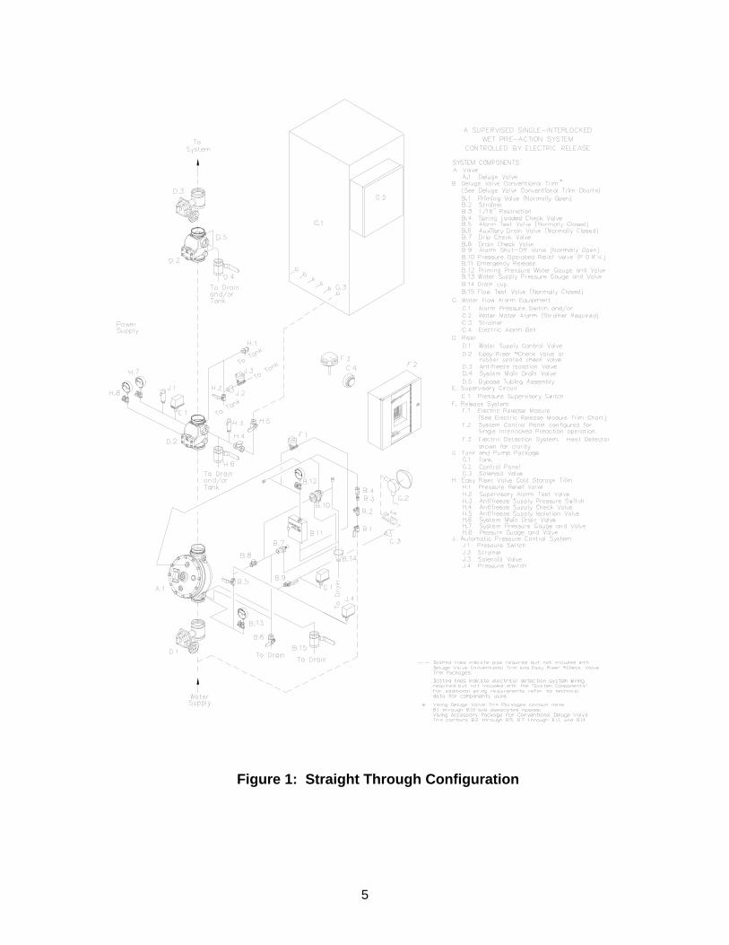
Figure 1: Straight Through Configuration
6
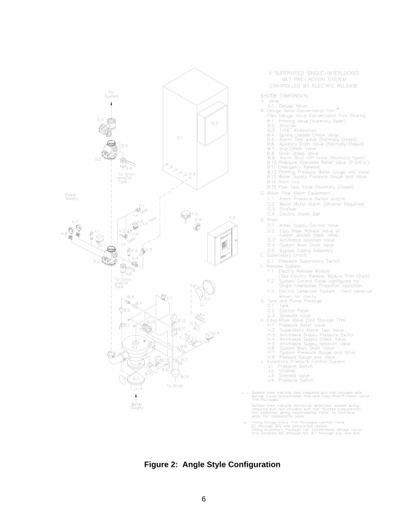
Figure 2: Angle Style Configuration
7
1.0 SYSTEM DESCRIPTION
The Viking ESFR “Pre-Primed Single Interlocked Preaction” Cold Storage System is a fixed fire protection system designed for installation in refrigerated or cold warehouse storage applications. This system is also appropriate for unheated storage applications in areas subject to freezing. This is a pre-primed preaction system with electric release that utilizes a deluge valve with conventional and electric release trims. The riser consists of two Viking Model F-1 Easy RiserTM Swing Check Valves, one with special cold trim and the second with by-pass trim to isolate the antifreeze in the system from the water supply. The sprinkler system piping is filled with low-pressure propylene glycol and water solution to supervise and pre-charge the discharge system and eliminate air pockets for more efficient system performance. The additional Easy RiserTM Check Valve is installed above the main check valve and is required to prevent thermal transfer of cold antifreeze from the freezer area onto the clapper surface of the primary check valve and minimize frost on the riser assembly. The pressure in the system is maintained by the CS-1 tank and pressure pump system that controls and maintains the desired solution pressure above the primary check valve. The detection system shall be capable of operation prior to or equal to an ESFR Sprinkler having an RTI (Response Time Index) of 50 or less. No linear detection shall be allowed. This limits the system to low temp spot heat, beam smoke or air sample type smoke system or equal. Upon operation of the detection system the deluge valve opens prior to sprinkler operation and pressurizes the sprinkler piping to the desired discharge pressure. Upon operation of the sprinkler(s), the pressurized propylene glycol/water solution is distributed from the sprinkler. Water from the supply system pushes out the propylene glycol/water solution at a very rapid rate due to the sprinkler orifice size and design pressures. The limited system volume ensures that 100% water will flow from the sprinklers at an appropriate stage of fire development. The CS-1 Tank and Pump System is designed to maintain supervisory system static pressure in the sprinkler piping using antifreeze and water premix. As the system operates, an alarm pressure switch is used to send a signal to the CS-1 system control to shut off the flow of antifreeze from the reservoir. Upon operation of the detection system, the deluge valve opens and pressurizes the system to desired starting discharge pressure. An alarm is activated due to water flow from the alarm pressure switch on the preaction trim. When the ESFR Sprinkler(s) operate the system is already pressurized and will discharge the antifreeze solution followed by water. Typically, only those sprinklers above or adjacent to the fire operate, minimizing water damage and contamination. Other antifreeze systems within the warehouse would not typically be activated. In the event of a broken sprinkler or sprinkler pipe without a fire condition, the deluge valve will hold back the water supply and only antifreeze will be drained from the sprinkler or broken pipe. This will prevent large amounts of water from being discharged and possible contamination of the antifreeze left in the system that could cause undesired freezing in the piping. A pressure supervisory switch on the antifreeze system located at the primary Easy RiserTM Check Valve adjacent to the deluge valve will provide an alarm of low-pressure condition. The antifreeze supply from the CS-1 pump must be manually shut off in this condition at the riser supply point.
8
In the event of a fire, the system pressure supervisory switch that controls the pump unit is wired through the alarm switch located on the deluge valve and to the CS-1 pump unit. In this case, the CS-1 pump solenoid valve is restricted from opening for the riser that is flowing to the fire area and stops the flow of antifreeze to the discharging system. In order to effectively apply 100% water as rapidly as possible, the system size must be limited in volume. Full-scale fire testing of the 50% propylene glycol and water premix solution and a system volume of 1,100 gallons (4 163 liters) has been performed successfully at Underwriters Laboratories Inc., resulting in UL Listing of the ESFR VK510 Sprinkler for use with 35% or 50% propylene glycol and water solution. The system uses either a 35% or 50% (depending on the minimum temperature in the area being protected) by volume mixture of propylene glycol and water premix solution. The propylene glycol and water mixture cools and adds wetting ability to control the fire until water is applied to suppress the fire. The area of coverage for a single system is dependent upon the volume of the system required to cover the area being protected. The hydraulic calculations are necessary in order to properly size the system piping. For refrigerated area systems, the piping system shall be pitched to drain complete system toward the riser and Easy RiserTM Check Valves with branch lines at ½” per 10 ft. (4 mm/m) and mains at ½” per 10 ft. (4 mm/m) run of pipe. For systems in unheated areas subject to freezing, branch lines shall be pitched at ½” per 10 ft. (4 mm/m) and mains at ¼” per 10 ft. (2 mm/m) run of pipe. This system shall be designed by qualified fire protection technicians, in conjunction with requirements of the Authorities Having Jurisdiction. Viking ESFR Cold Storage Systems are designed to meet the UL Listing requirements described in Viking technical data for ESFR K25.2 Sprinkler VK510 for use with 35% or 50% propylene glycol and water solution, and the standards of NFPA 13 or other organizations, and also with the provisions of governmental codes, ordinances, and standards where applicable. This system shall meet all requirements of ESFR installations except where specified in this owner's manual. This system can be considered a wet system due to the system being filled with the approved antifreeze solution, and operation of the detection and preaction system will provide water supply and pressurized solution at the sprinkler upon operation.
When using this system, ceiling-only sprinklers are required and no in-rack sprinklers are needed. The following storage configurations are required:
- Single-row, double-row, and multiple-row rack storage is required and sprinklers shall be located in accordance with applicable Viking technical data and the latest recognized storage installation rules of NFPA or the Authority Having Jurisdiction (AHJ).
- Open rack storage is required, and sprinklers shall be located in
accordance with applicable Viking technical data (refer to the latest issue of sprinkler data page 46 a-c) and the latest recognized storage installation rules of NFPA or the Authority Having Jurisdiction (AHJ).
9
2.0 ESFR SPRINKLER DESCRIPTION
Viking ESFR Pendent K 25.2 Sprinkler VK510 is UL Listed for use with a maximum 50% by volume factory premix propylene glycol and water antifreeze solution. This listing is based on full-scale fire testing at Underwriter’s Laboratories. The following limitations of system design and application shall apply: 2.1 Storage Arrangements: Solid-piled or open rack (single, double, multiple, or
portable), palletized storage (pallets limited to wood), with no open-top containers or solid shelves.
2.2 Commodity Classification: Limited to Class II or less. 2.3 Maximum Storage/Ceiling Heights and Minimum Pressure Requirements:
• Storage height up to 35 ft. (10,7 m) with ceiling height up to 40 ft. (12,2 m) with
a minimum system design pressure of 40 PSI (278 kPa). OR: • Storage height up to 40 ft. (12,2 m) with ceiling height up to 45 ft-3 in. (13,8 m)
with a minimum system design pressure of 60 PSI (414 kPa). 3.0 SYSTEM DESIGN
3.1 Hydraulic Calculations:
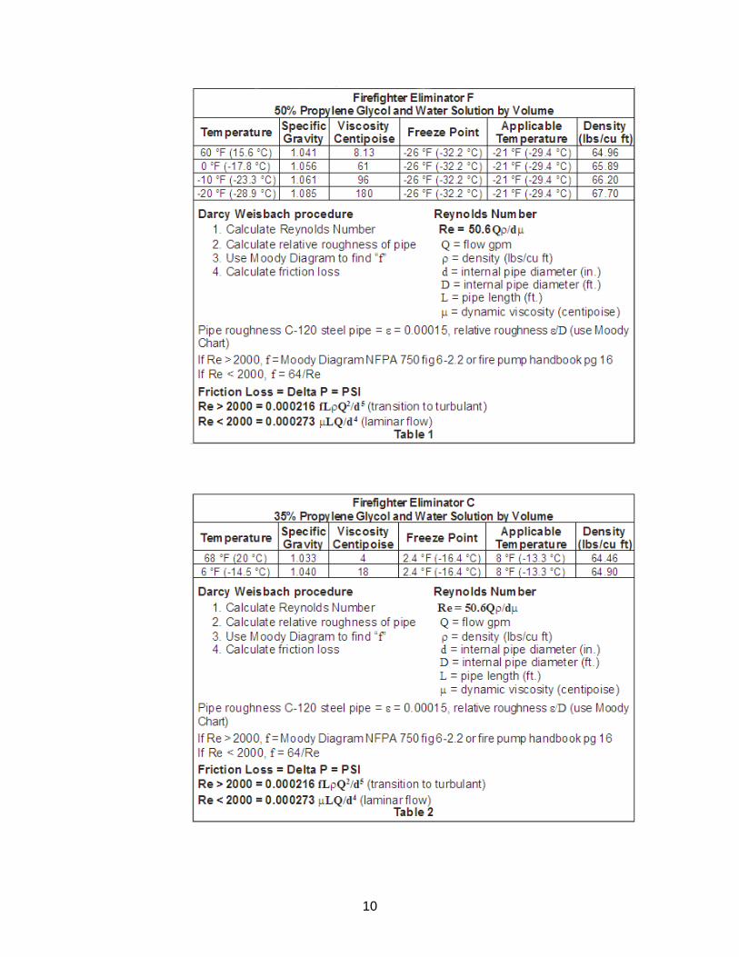
At -21 °F (-29.4 °C), the 50% solution of propylene glycol/water solution will have a viscosity of 200 centipoise, as opposed to water at 1 centipoise at 70 °F (21.1 °C). Two sets of hydraulic calculations will be required for the system piping; one utilizing Hazen-Williams method of determining friction loss, and one utilizing Darcy-Weisbach method of determining friction loss. The Hazen-Williams friction loss factors will be utilized for flowing water through the piping, the Darcy-Weisbach friction loss factors will be utilized for flowing propylene glycol/water solution through the system piping at the lowest operating temperature. The information in Table 1 is provided for Firefighter Eliminator F 50% propylene glycol/water pre-mix solution, while the information in Table 2 is provided for Firefighter Eliminator C 35% propylene glycol/water pre-mix solution.
10
11
3.2 Hydraulic Calculation Procedure:
1. A calculation with a design of twelve ESFR K25.2 VK510 Sprinklers and water, using four sprinklers on three most remote lines, discharging at the minimum design pressure for the hazard, with piping friction loss determined by Hazen- Williams method of determining friction loss in piping.
2. A second hydraulic calculation with a design of six K25.2 ESFR sprinklers
using propylene glycol and the physical properties at the discharge temperatures, using four sprinklers on the most remote line and two sprinklers on the second most remote line, discharging at a minimum design pressure for the hazard, with piping friction loss determined by the Darcy-Weisbach method of determining friction loss in piping.
3. The 1,100 gallon (4,163 liter) volume restriction for tree type piping
configuration is for the piping included in the remote area (12 sprinklers) and the supply main piping back to the base of the sprinkler riser above the primary Easy RiserTM Check Valve clapper.
4. Additional mains and sprinkler lines attached to the system, but not in the direct
path to the sprinkler riser base, need not be considered for the system volume limitation if acceptable by the Authority Having Jurisdiction.
4.0 PRE-PRIMED SINGLE INTERLOCKED PREACTION SYSTEM FOR COLD
STORAGE The Viking “Pre-Primed Single Interlocked Preaction” Cold Storage System is electrically operated using a listed releasing control panel, listed detection system as described in the technical data, and a listed Viking single interlocked preaction assembly, two Viking Easy RiserTM Check Valves. The first or primary Easy RiserTM Check Valve and trim includes connections for antifreeze supply from the Viking Model CS-1 pump control assembly that also includes a reservoir for antifreeze and controls. A pressure switch to control the supervisory antifreeze pressure is also included. The antifreeze must fill the system less any air pockets in order to prevent water from entering cold storage area and contaminating the antifreeze mixture, which could cause freezing. A Viking automatic air vent assembly (Model AV-1) is recommended for installation at the end of all branch lines and high points of the supply mains. A second Easy RiserTM Check Valve that includes a system main drain and a by-pass line is installed approximately 5 to 10 ft (1,5 to 3,0 m) above or downstream of the first check valve between the freezer wall and the primary check valve. This valve is required to protect the riser assembly and clapper of the first check valve from freezing due to hydrodynamic thermal transfer of cold antifreeze from the freezer to the riser check valve. The by-pass line is required to allow all system controls on the primary check valve to function properly. This valve also helps to minimize insulation and heat trace requirements to the riser system outside of the freezer.
• The single interlocked preaction control valve assembly is a standard Viking Model E-1 or F-1 Deluge Valve including Conventional Deluge Trim with Electric Release. This valve controls the supply water to the system having a static supply pressure capable of supplying adequate starting pressure of the most

12
remote sprinklers as calculated. The operation of the control valve is caused by the operation of the detection system after sensing a fire condition. The installation position must be directly adjacent and at the bottom of the supply riser to the area of protection and must be in a heated room that maintains a minimum temperature of 40 °F (4 °C).
• The primary Easy RiserTM Check Valve is a Viking Model F-1 that includes a
system main drain, inlet connection for antifreeze supply, system pressure switch, system supervisory switch and gauges to monitor system antifreeze pressure and control the CS-1 antifreeze pump system. This check valve must be located downstream of the deluge valve (within 1 to 2 ft maximum). It is recommended to install this check valve as close to floor level as convenient in order to properly maintain the valve. The inlet side of valve is atmospheric air, while the outlet will be the desired static antifreeze pressure to the system. Options for the check valve include pressure relief valve (see selection below) and automatic pressure control system for variable temperature freezers and coolers described below.
• A second thermal isolation valve (Viking Model F-1 Easy RiserTM Swing Check
Valve) is installed as close to the freezer wall as possible but at least 5 ft above or downstream of the primary check valve within the heated area of the riser room to prevent thermal migration of the antifreeze from the freezer and protect the primary check valve from freezing near the atmospheric air surface of the clapper and seat. This valve includes a main drain and a special 3/8” I.D. copper tube by-pass to allow proper system pressure monitoring and prevent thermal migration to primary check valve. The main drain must be piped to the main drain of the primary check valve and returned to the recovery tank.
• Releasing control panel shall be a listed releasing panel capable of single hazard
and two-zone operation. The control panel shall be provided with a 90-hour backup battery supply. Zone 1 shall operate the releasing circuit and alarm. Zone 2 shall detect low pressure antifreeze and provide alarm.
• Detection is required for this system. The detection system shall be capable of
operation prior to or equal to an ESFR Sprinkler having an RTI (Response Time Index) of 50 or less. No linear detection shall be allowed. This limits the system to low temp spot heat, beam smoke or air sample type smoke system or equal.
5.0 SYSTEM INSTALLATION REQUIREMENTS AND CONSIDERATIONS
5.1 Tree Configuration - ESFR Cold Storage System
A tree type piping configuration is required for this type system over the grid type system because this type of system is easier to set up for drainage. Also, with a center feed main supplying branch lines, the flow is directed toward the first open sprinklers. This allows the antifreeze solution to be expelled from lines and mains leading directly to open sprinklers and to be replaced with 100% water much faster than in grid type systems. For tree systems utilizing this system, the mains
13
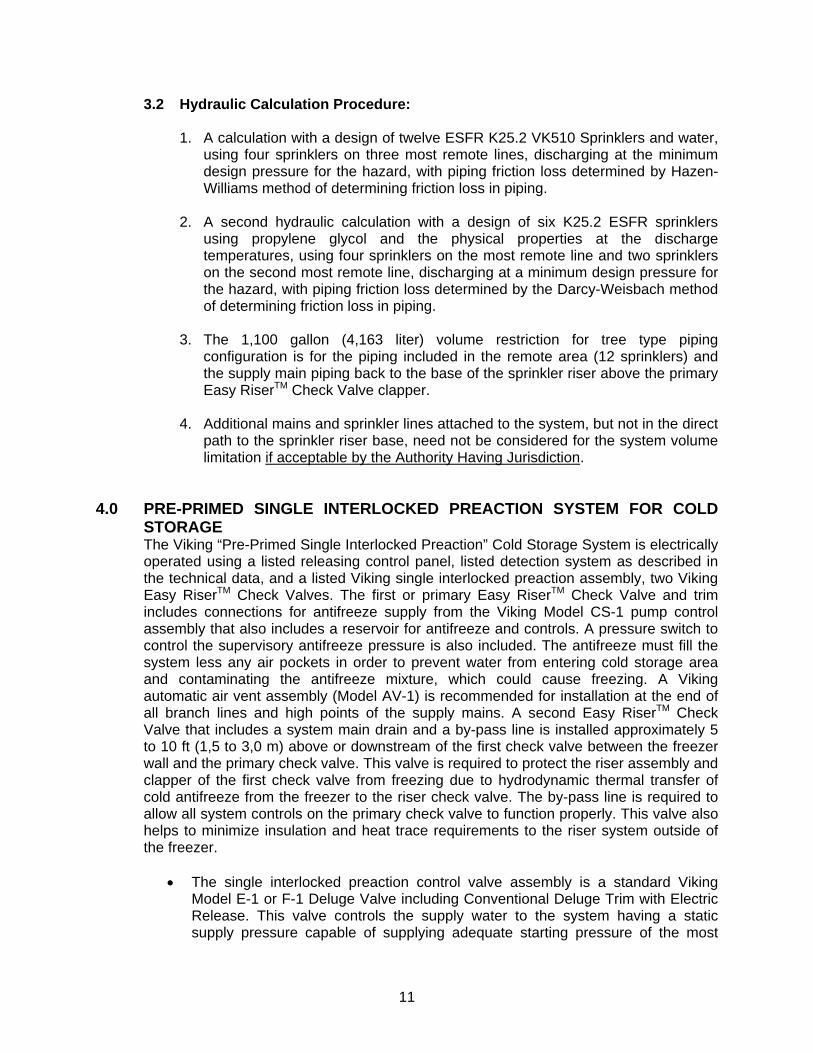
or lines should not be looped together as done in some dry pipe and preaction systems. Tree Sprinkler System: A system of dead-end branch lines centrally fed by a cross main.
The discharge pressure for all sprinklers flowing must maintain at a minimum of the required design. The 1,100 gallon (4,163 liter) system volume is established by adding the piping volume from the remote area to the top of the Easy RiserTM Check Valve at the base of the riser. The actual propylene glycol solution requirement for the system is determined by adding all the system piping volume together. All NFPA 13 installation criteria and AHJ requirements apply to installation of the Viking ESFR Cold Storage System with the following exceptions: • Commodity limited to Class II or less (limited to wood pallets). • Maximum ceiling height to bottom of inside upper deck is 40 ft. (12,2 m) with
a maximum storage height of 35 ft. (10,7 m) and a minimum sprinkler discharge pressure of 40 PSI (278 kPa). OR:
• Maximum ceiling height to bottom of inside upper deck is 45 ft-3 in. (13,8 m) with maximum storage height of 40 ft. (12,2 m) and a minimum sprinkler discharge pressure of 60 PSI (414 kPa).
• Where the minimum temperature in the area being protected is 8 °F (-13.3 °C) or above, 35% percent by volume of propylene glycol factory premixed with water must be used. Viking requires Firefighter Eliminator C premix 35% propylene glycol/water mixture with a freeze temperature rating (freeze point) of 2.4 °F (-16.4 °C). OR:
14
• Where the minimum temperature in the area being protected is between 8 °F (-13.3 °C) and -21 °F (-29.4 °C), the percentage by volume of propylene glycol must be 50%, factory premixed with water for antifreeze solution. Viking requires Firefighter Eliminator F type 50% propylene glycol/water mixture, with a freeze temperature rating (freeze point) of -26 °F (-32.2 °C).
• Minimum ambient temperature is -21 °F (-29.4 °C). NOTE: The minimum temperature is NOT an average in the freezer, but is the lowest temperature for the system.
• Maximum system volume is 1,100 gallons (4 163 liters). Refer to calculation to determine volume.
• Use ordinary temperature rated 165 °F (74 °C) Viking ESFR K25.2 Sprinkler VK510. Exception: Intermediate temperature rated 205 °F (96 °C) Viking ESFR VK510 K25.2 Sprinklers that are intended for installation in close proximity to heat sources may be applied only as referenced in NFPA 13.
• The piping system must be pitched for drainage of the system after operation. For refrigerated area systems, the piping system shall be pitched to drain complete system toward the riser and alarm valve with branch lines at ½” per 10 ft. (4 mm/m) and mains at ½” per 10 ft. (4 mm/m) run of pipe. For systems in unheated areas subject to freezing, branch lines shall be pitched at ½” per 10 ft. (4 mm/m) and mains at ¼” per 10 ft. (2 mm/m) run of pipe.
• The system must be designed so maximum operating pressure of the system does not exceed 175 PSI (1 207 kPa) at the sprinkler, including test pressures of pumps at zero flow.
• Detection System shall be capable of operation prior to or equal to an ESFR Sprinkler having an RTI (Response Time Index) of 50 or less. No linear detection shall be allowed. This limits the system to low temp spot heat, beam smoke or air sample type smoke system or equal.
5.1.1 Piping System to Sprinklers
Tree type piping configurations vary. There are side or end feeds, offset feeds, and center feeds. Many times the configuration of the tree system piping is dictated by building features or by hydraulic calculations. The maximum system volume must be maintained and is calculated at a maximum from the primary Easy RiserTM Check Valve, including all piping to the remote sprinklers (refer to calculation to determine volume). The deluge valve and trim system, system check valves along with all antifreeze and supply piping, must be installed in a heated area that is maintained at or above 40 °F (4 °C). Insulating the fire sprinkler riser will be required to eliminate condensation and frost from developing on the piping in the heated area. Insulate the riser main from the freezer wall to the isolation check valve. If the primary system check valve is close enough to isolation check valve [less than the 5 ft (1,5 m) recommended] and freezer separation wall to cause freezing of water and condensation on piping below the check valve, then a listed heat trace heating system may be required for the riser piping above and below the primary check valve that will maintain a temperature under the insulation of 70 °F (21.1 °C) to eliminate condensation and maintain internal temperature of
15
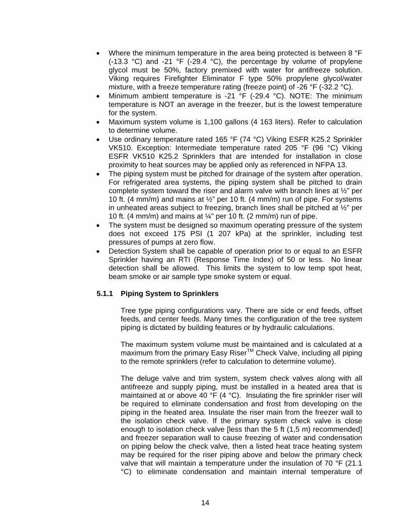
solution above freezing for air below the primary check valve. Due to difficulty in servicing and insulating the check valve, it is recommended to install the deluge and check valve near floor level at the base of the main riser in the heated area allowing approximately 1 to 2 ft between the outlet of deluge valve and inlet of the primary Easy RiserTM Check Valve and install the maximum length of pipe from the primary Easy RiserTM Check Valve to the Isolation check valve that is between the freezer wall and the primary check valve. Air vent valves or manual bleed valves must be installed at the highest and most remote points on the tree piping system in order to vent out all air during fill of the 35% or 50% premix of propylene glycol/water solution in the system. Additional vent or bleed valves shall be installed on the end of each branch line at high points and feed mains at high points to ensure air is vented from the system. This is required in order to eliminate compressible gas (air) from the system when setting supervisory pressure from the antifreeze CS-1 pump system. Also, the manual vent valves may be used for multiple sample points of the system for quality testing of the antifreeze solution. The Viking Model AV-1 Automatic Air/Vent Valve is recommended for this use. It automatically vents air during fill and breaks the vacuum for faster drainage of the system when performing maintenance or draining the system after operation.
AV-1 Air Vent Assembly
5.1.1.1 General Piping and Material Recommendations
• In order to prevent leaks and preserve the antifreeze solution, it is imperative that grooved pipe ends are smooth, round, and free of burrs, flat spots, and weld seam
16
imperfections. Also, pipes should be capped to prevent contaminant during shipping, storage, etc.
• Antifreeze solution is very lubrise and difficult to seal
compared to plain water and initial care in pipe connections will minimize leaks at start-up. Also, antifreeze solution will prevent microbiological attack to piping material 5 times greater than water. Cleanliness is required to improve longevity of solution. Prefabricated pipe should be capped during shipping and staging prior to installation.
• If grooved couplings are utilized in the system piping
installation, "flush seal" gaskets, low temperature EPDM rubber and lube are required. Pooling of propylene glycol in the system shall be eliminated. Vent valves shall be minimum ½” ball valves with ½” plug. Vent valves can double as solution test points as well; the Viking Model AV-1 Air/Vent Valve is recommended, as it includes strainer and test connection for automatic venting during fill and drain of the system. Material installed on the system shall be compatible with propylene glycol solution. A re-claim tank with adequate capacity of the largest system(s) shall be located near the system riser(s). System drain piping shall be arranged to discharge to the re-claim tank.
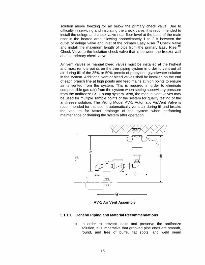
5.1.2 Primary Check Valve Main Drain
The main drain outlet should be directed to an appropriate location, and the drain valve shall be installed at an accessible level so it can be operated from the floor level. Installing the isolation Easy RiserTM Check valve at an elevation near the horizontal mains supplying the system and 10 to 15 ft (3,0 to 4,5 m) above the
primary check valve will reduce the cold thermal transfer of propylene glycol solution in the system piping to the vertical system riser and minimize frosting on the system riser. The main drain valves from the isolation check and primary check valves shall be installed at an accessible level, as the solution will be trapped in the drop leg to the drain valve and will not affect the total calculation for the system. The main drain valve will be used to drain the system piping downstream of the Easy RiserTM Check Valves. As the cold antifreeze from the freezer area will emit cold thermal transfer, it will be required to insulate the drain pipe to prevent frosting.
17
Propylene glycol/water solutions are designed to be installed on systems supplied by potable water supplies. Local authorities should be consulted prior to draining system to storm sewers or to natural drainage areas. In the main drain line between the valve and Easy RiserTM Check Valves inlet, a tee is provided on the check valve trim with a 1” NPT connection for supply and maintenance of the antifreeze solution to the system above the primary Easy RiserTM Check Valve.
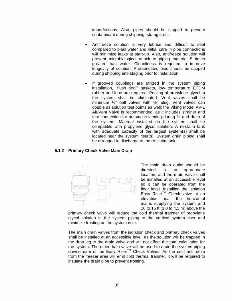
5.1.3 Reclaim Tank
An atmospheric storage tank is to be installed for the system(s) that is of adequate capacity of the largest system volume installed. The tank shall be utilized as a reclaim tank for the propylene glycol solution in the system piping when the system(s) are drained for system service and for discharge of propylene glycol solution if system pressure exceeds 175 PSI (1 207 kPa) at the sprinklers. The ball valve must be shut before the switch on the CS-1 Panel is placed in Automatic Mode.
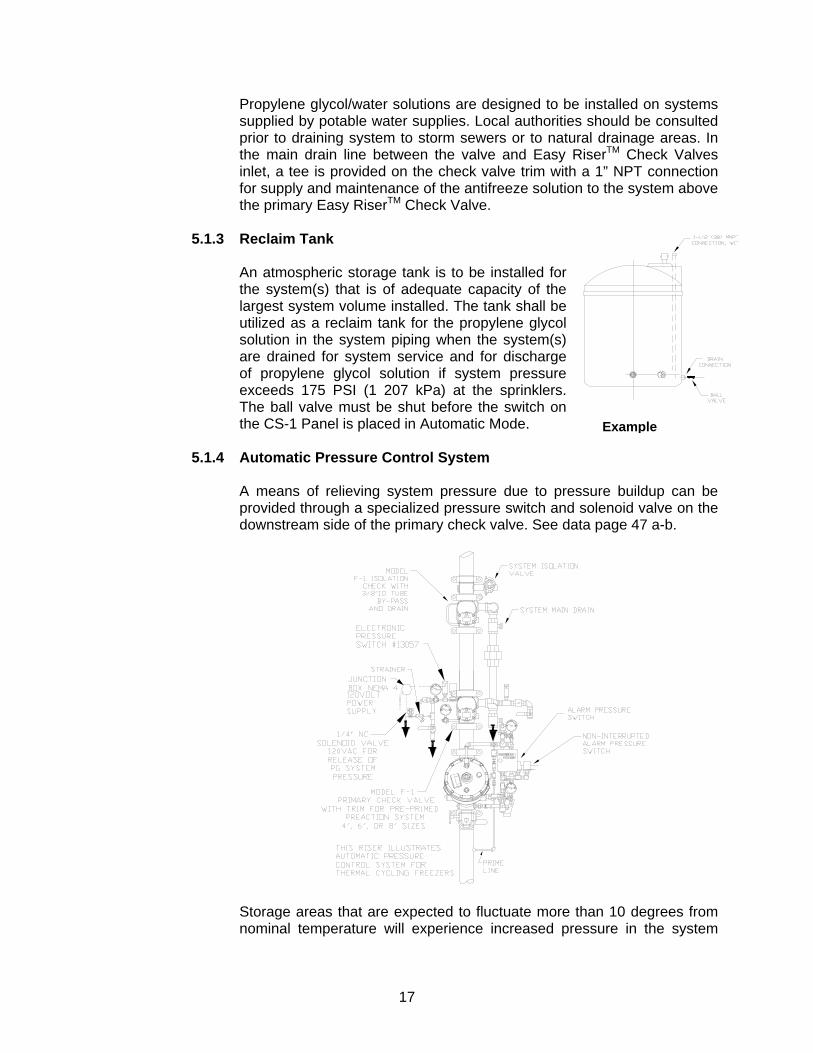
5.1.4 Automatic Pressure Control System
A means of relieving system pressure due to pressure buildup can be provided through a specialized pressure switch and solenoid valve on the downstream side of the primary check valve. See data page 47 a-b.
Storage areas that are expected to fluctuate more than 10 degrees from nominal temperature will experience increased pressure in the system
Example
18
piping due to expansion of the propylene glycol when the temperature rises in the storage area. In order to prevent the pressure relief valve (PRV) on the Easy RiserTM valve trim from operating, the pressure control system is set to maintain pressure below the set point of the PRV and above the system maintenance pressure. The alarm pressure switch will prevent the APCS from operating when the deluge valve has operated. Prior to installation of system, maximum temperature changes are required to be considered to determine possible expansion and contraction rate of propylene glycol solution. If the contraction rate is greater than the storage tank that accompanies excess pressure pump, an additional supply tank to supplement excess pressure pump shall be installed.
5.1.5 Solution Test Valves
Multiple propylene glycol/water solution test valves are to be installed on the system piping for semi-annual testing with a refractometer. The testing stated in this section is more restrictive than the required test frequency indicated in NFPA 25. Solution test valves should be located in several areas of the system piping: • The most practical location immediately downstream of the primary
Easy RiserTM check valve. • The most remote location from the Easy RiserTM check valve. • One valve located at the end of 50% of the line piping directly on the
Model AV-1 Air/Vent Valve assembly. • A test valve shall be located at the end of the nearest line on the tree
system and the last line on the tree system. If the propylene glycol/water solution becomes diluted or does not pass the refractometer test, the entire system is to be drained. All sections of trapped piping are to be drained. Five percent (5%) of the pendent ESFR sprinklers are to be removed and inspected for frozen solution. If any of the pendent ESFR sprinklers are found with frozen solution, then all the pendent ESFR sprinklers are to be removed and replaced with new Viking K25.2 Pendent ESFR VK510 Sprinklers prior to re-charging the system with new 35% or 50% premix propylene glycol/water solution. If the 5% of removed sprinklers are not damaged, they can be re-installed in the system. (Refer to the system service schedule for additional solution tests.) Sampling shall be taken from multiple points within the freezer system. Ensure that the CS-1 pump antifreeze supply control system is returned to the fully pressurized state once fluid sampling is completed. Antifreeze solution shall be checked semi-annually with a refractometer to detect the concentration of antifreeze solution and effectiveness against freezing.
19
5.1.6 Re-Charging System Piping with 35% or 50% Premix Propylene Glycol/Water Solution
A suitable portable pump can be utilized to fill the system. The CS-1 pump can be used for filling the system initially at 15 GPM (56 l/min) to 100 ft. head pressure or system static pressure, however, it is a less efficient pump for filling the system because of the duration of time required to do so. The CS-1 pump is to be utilized to bring the antifreeze solution to maintenance pressure above the Easy RiserTM check valve, [normally 50 PSI (345 kPa)] and is designed to maintain system pressure once the system is initially filled. Also, repeat air bleed from the system as described above. If using the Viking Model AV-1 Air/Vent Valve assembly, the air will automatically be vented during the fill cycle.
5.1.7 Expansion of Antifreeze in the System
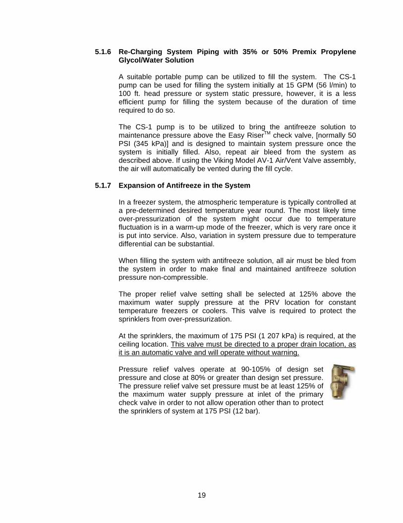
In a freezer system, the atmospheric temperature is typically controlled at a pre-determined desired temperature year round. The most likely time over-pressurization of the system might occur due to temperature fluctuation is in a warm-up mode of the freezer, which is very rare once it is put into service. Also, variation in system pressure due to temperature differential can be substantial. When filling the system with antifreeze solution, all air must be bled from the system in order to make final and maintained antifreeze solution pressure non-compressible. The proper relief valve setting shall be selected at 125% above the maximum water supply pressure at the PRV location for constant temperature freezers or coolers. This valve is required to protect the sprinklers from over-pressurization. At the sprinklers, the maximum of 175 PSI (1 207 kPa) is required, at the ceiling location. This valve must be directed to a proper drain location, as it is an automatic valve and will operate without warning. Pressure relief valves operate at 90-105% of design set pressure and close at 80% or greater than design set pressure. The pressure relief valve set pressure must be at least 125% of the maximum water supply pressure at inlet of the primary check valve in order to not allow operation other than to protect the sprinklers of system at 175 PSI (12 bar).
20
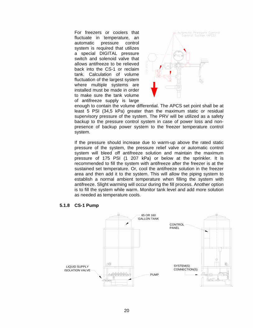
For freezers or coolers that fluctuate in temperature, an automatic pressure control system is required that utilizes a special DIGITAL pressure switch and solenoid valve that allows antifreeze to be relieved back into the CS-1 or reclaim tank. Calculation of volume fluctuation of the largest system where multiple systems are installed must be made in order to make sure the tank volume of antifreeze supply is large enough to contain the volume differential. The APCS set point shall be at least 5 PSI (34,5 kPa) greater than the maximum static or residual supervisory pressure of the system. The PRV will be utilized as a safety backup to the pressure control system in case of power loss and non-presence of backup power system to the freezer temperature control system. If the pressure should increase due to warm-up above the rated static pressure of the system, the pressure relief valve or automatic control system will bleed off antifreeze solution and maintain the maximum pressure of 175 PSI (1 207 kPa) or below at the sprinkler. It is recommended to fill the system with antifreeze after the freezer is at the sustained set temperature. Or, cool the antifreeze solution in the freezer area and then add it to the system. This will allow the piping system to establish a normal ambient temperature when filling the system with antifreeze. Slight warming will occur during the fill process. Another option is to fill the system while warm. Monitor tank level and add more solution as needed as temperature cools.
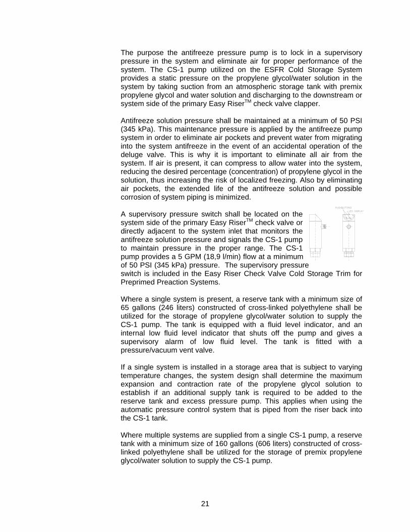
5.1.8 CS-1 Pump
ISOLATION VALVESYSTEM(S)CONNECTION(S)
PUMP
65 OR 160
CONTROLPANEL
LIQUID SUPPLY
GALLON TANK
21
The purpose the antifreeze pressure pump is to lock in a supervisory pressure in the system and eliminate air for proper performance of the system. The CS-1 pump utilized on the ESFR Cold Storage System provides a static pressure on the propylene glycol/water solution in the system by taking suction from an atmospheric storage tank with premix propylene glycol and water solution and discharging to the downstream or system side of the primary Easy RiserTM check valve clapper. Antifreeze solution pressure shall be maintained at a minimum of 50 PSI (345 kPa). This maintenance pressure is applied by the antifreeze pump system in order to eliminate air pockets and prevent water from migrating into the system antifreeze in the event of an accidental operation of the deluge valve. This is why it is important to eliminate all air from the system. If air is present, it can compress to allow water into the system, reducing the desired percentage (concentration) of propylene glycol in the solution, thus increasing the risk of localized freezing. Also by eliminating air pockets, the extended life of the antifreeze solution and possible corrosion of system piping is minimized. A supervisory pressure switch shall be located on the system side of the primary Easy RiserTM check valve or directly adjacent to the system inlet that monitors the antifreeze solution pressure and signals the CS-1 pump to maintain pressure in the proper range. The CS-1 pump provides a 5 GPM (18,9 l/min) flow at a minimum of 50 PSI (345 kPa) pressure. The supervisory pressure switch is included in the Easy Riser Check Valve Cold Storage Trim for Preprimed Preaction Systems. Where a single system is present, a reserve tank with a minimum size of 65 gallons (246 liters) constructed of cross-linked polyethylene shall be utilized for the storage of propylene glycol/water solution to supply the CS-1 pump. The tank is equipped with a fluid level indicator, and an internal low fluid level indicator that shuts off the pump and gives a supervisory alarm of low fluid level. The tank is fitted with a pressure/vacuum vent valve. If a single system is installed in a storage area that is subject to varying temperature changes, the system design shall determine the maximum expansion and contraction rate of the propylene glycol solution to establish if an additional supply tank is required to be added to the reserve tank and excess pressure pump. This applies when using the automatic pressure control system that is piped from the riser back into the CS-1 tank. Where multiple systems are supplied from a single CS-1 pump, a reserve tank with a minimum size of 160 gallons (606 liters) constructed of cross-linked polyethylene shall be utilized for the storage of premix propylene glycol/water solution to supply the CS-1 pump.
22
Where multiple riser systems exist, the antifreeze solution system can be supplied to multiple risers from a single pump system and the pressure switch for each system must be controlled through the pump system control panel. When the pressure drops below set point, a solenoid valve supplied from the CS-1 pump shall open to allow flow of antifreeze solution into the system(s) that are low on pressure. When pressure is established, the solenoid valve will shut off. Where multiple systems are supplied from a single CS-1 pump and a single system operates due to water flow from open sprinkler, the control panel is signaled by the alarm or flow switch of operating riser and shuts off the supply solenoid to that riser. The remaining systems maintain supervisory pressure. This prevents contamination of antifreeze solution with water during operation of a single system and eliminates air pockets that may contaminate antifreeze solution or cause pipe corrosion.
5.1.9 Propylene Glycol and Water Solution Premix
Premix 35% or 50% propylene glycol and water solution that is certified by the manufacturer or a third-party agency is to be installed in the system piping. Field mixing of propylene glycol and site water is strictly prohibited, as the control of the mixture cannot be assured. Firefighter Eliminator C 35% premix solution or Firefighter Eliminator F 50% premix solution (refer to data pages 49 a-b and 50 a-b) are required by Viking, as they are mixed in the proper proportion and were utilized for the research fire tests. Firefighter Eliminator C and Firefighter Eliminator F include corrosion inhibitors and de-ionized water to prevent the minerals in site water from reacting with the corrosion inhibitors. This extends the usable life of the propylene glycol/water solution. Improper field mixing of solution can result in reduced capability to prevent freezing or to control a fire. The corrosion inhibitors included in the premix provide corrosion control and microbiological control of the system piping and components.
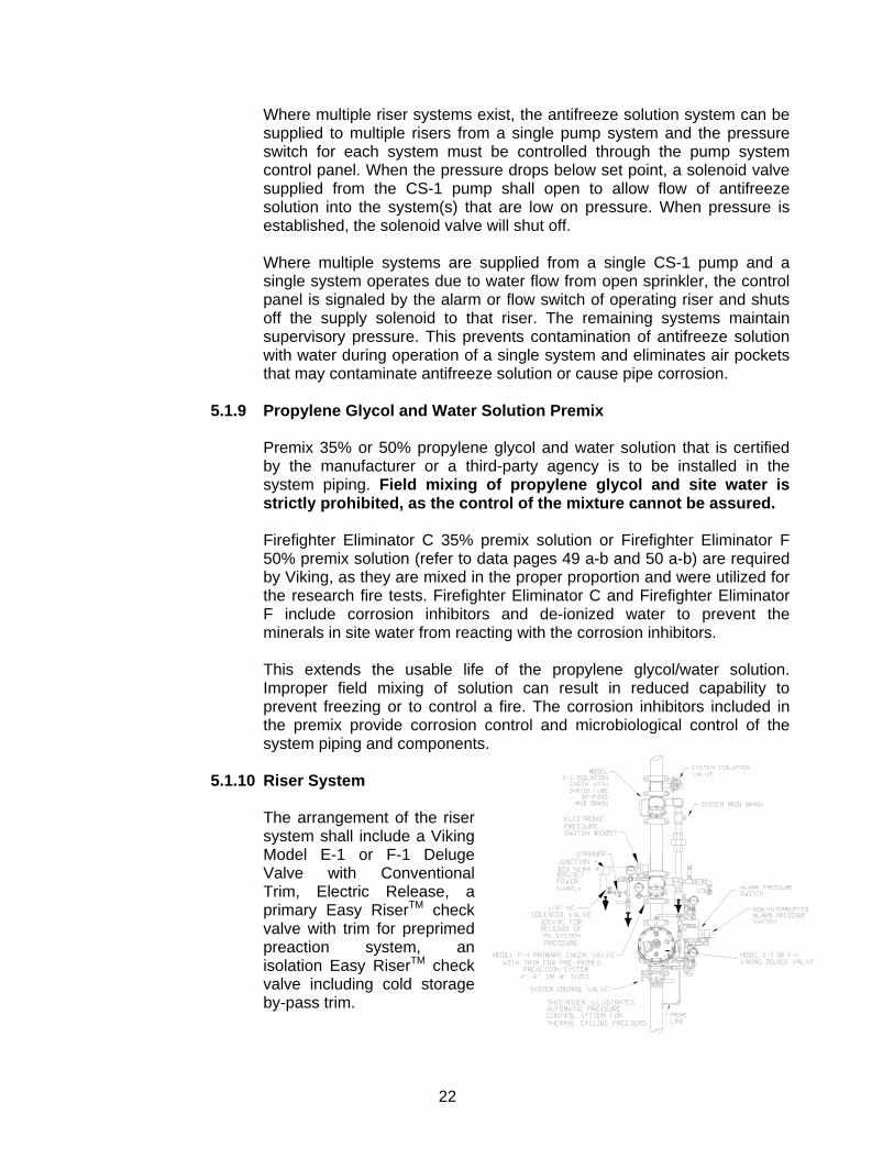
5.1.10 Riser System
The arrangement of the riser system shall include a Viking Model E-1 or F-1 Deluge Valve with Conventional Trim, Electric Release, a primary Easy RiserTM check valve with trim for preprimed preaction system, an isolation Easy RiserTM check valve including cold storage by-pass trim.
23
The system must include a supervised system control valve upstream of the deluge valve and a supervised system isolation valve downstream of the isolation check valve. The downstream system isolation valve is required to facilitate maintenance of the system and isolation of antifreeze solution during maintenance and testing. A pressure relief valve on the antifreeze side of the primary check valve shall be pre-set to protect the sprinklers at 175 PSI (1 207 kPa) and piped to drain. This will handle over-pressurization due to thermal differentials in the area of the antifreeze piping and system operation. Consideration of location height of PRV relative to the sprinklers must be taken into account. Calculate the differential height and specific gravity of antifreeze at the operating temperature of the freezer and size the PRV relief pressure accordingly. The alarm line of the deluge valve shall be attached to an alarm pressure switch (and mechanical water motor alarm, if required) that activates an alarm due to activation of the system. An additional supervisory pressure switch on the primary check valve system side is required in order to provide a low pressure alarm in the case of antifreeze pressure loss due to sprinkler operation without a fire condition. In this case the antifreeze supply must be manually shut off to the low-pressure riser. There is an isolation valve located on the antifreeze inlet line of the riser primary check valve.
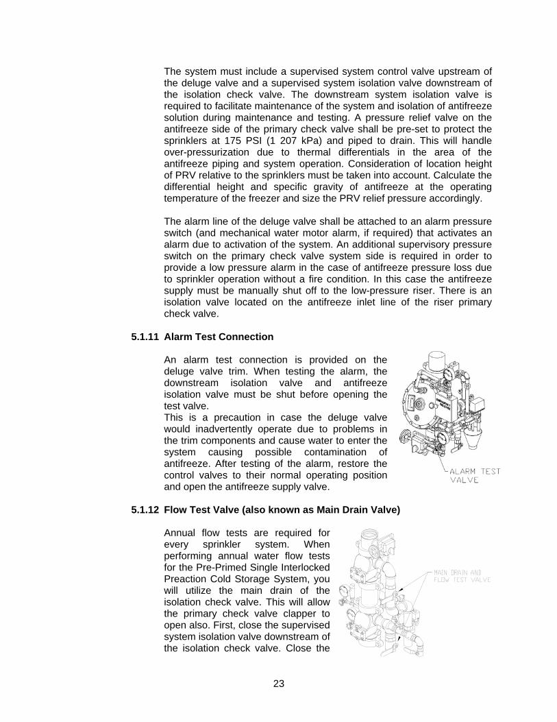
5.1.11 Alarm Test Connection
An alarm test connection is provided on the deluge valve trim. When testing the alarm, the downstream isolation valve and antifreeze isolation valve must be shut before opening the test valve. This is a precaution in case the deluge valve would inadvertently operate due to problems in the trim components and cause water to enter the system causing possible contamination of antifreeze. After testing of the alarm, restore the control valves to their normal operating position and open the antifreeze supply valve.
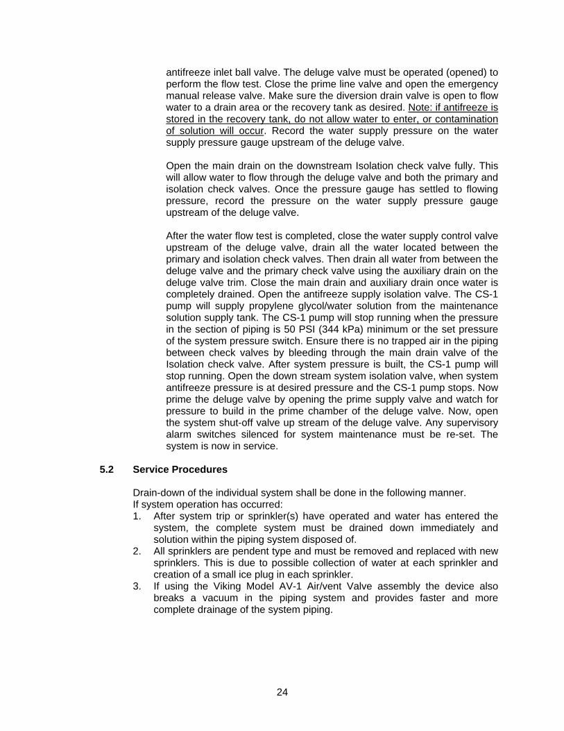
5.1.12 Flow Test Valve (also known as Main Drain Valve)
Annual flow tests are required for every sprinkler system. When performing annual water flow tests for the Pre-Primed Single Interlocked Preaction Cold Storage System, you will utilize the main drain of the isolation check valve. This will allow the primary check valve clapper to open also. First, close the supervised system isolation valve downstream of the isolation check valve. Close the
24
antifreeze inlet ball valve. The deluge valve must be operated (opened) to perform the flow test. Close the prime line valve and open the emergency manual release valve. Make sure the diversion drain valve is open to flow water to a drain area or the recovery tank as desired. Note: if antifreeze is stored in the recovery tank, do not allow water to enter, or contamination of solution will occur. Record the water supply pressure on the water supply pressure gauge upstream of the deluge valve. Open the main drain on the downstream Isolation check valve fully. This will allow water to flow through the deluge valve and both the primary and isolation check valves. Once the pressure gauge has settled to flowing pressure, record the pressure on the water supply pressure gauge upstream of the deluge valve. After the water flow test is completed, close the water supply control valve upstream of the deluge valve, drain all the water located between the primary and isolation check valves. Then drain all water from between the deluge valve and the primary check valve using the auxiliary drain on the deluge valve trim. Close the main drain and auxiliary drain once water is completely drained. Open the antifreeze supply isolation valve. The CS-1 pump will supply propylene glycol/water solution from the maintenance solution supply tank. The CS-1 pump will stop running when the pressure in the section of piping is 50 PSI (344 kPa) minimum or the set pressure of the system pressure switch. Ensure there is no trapped air in the piping between check valves by bleeding through the main drain valve of the Isolation check valve. After system pressure is built, the CS-1 pump will stop running. Open the down stream system isolation valve, when system antifreeze pressure is at desired pressure and the CS-1 pump stops. Now prime the deluge valve by opening the prime supply valve and watch for pressure to build in the prime chamber of the deluge valve. Now, open the system shut-off valve up stream of the deluge valve. Any supervisory alarm switches silenced for system maintenance must be re-set. The system is now in service.
5.2 Service Procedures
Drain-down of the individual system shall be done in the following manner. If system operation has occurred: 1. After system trip or sprinkler(s) have operated and water has entered the
system, the complete system must be drained down immediately and solution within the piping system disposed of.
2. All sprinklers are pendent type and must be removed and replaced with new sprinklers. This is due to possible collection of water at each sprinkler and creation of a small ice plug in each sprinkler.
3. If using the Viking Model AV-1 Air/vent Valve assembly the device also breaks a vacuum in the piping system and provides faster and more complete drainage of the system piping.
25
5.3 Taking the System Out of Service
If the system has to be taken out of service for maintenance on the system piping, follow these instructions: 1. Close the water supply control valve to the riser being serviced. 2. Close the antifreeze supply valve to the riser being serviced. 3. If the system is being serviced, then the solution in the system can be
drained into clean containers or reclaim tank and reused as long as water has not entered the systems. Solution should be checked at various points while draining for proper refractometer readings to verify freeze-protection properties.
4. Open vent/bleed valves at high points of the system or if the AV-1 Vent Valve is applied it will automatically open.
5. Open the main drain and collect solution in clean containers or recovery tank for re-use in system.
6. After the system is completely drained from the main drain, open any low-point drains to remove the remaining solution from the system.
5.4 Placing the System in Service
Placing the system in service after it has been completely drained: 1. Close the main drain valve on the riser. 2. Connect the propylene glycol/water solution fill pump (NOT the CS-1 pump)
to the connection located on the main drain assembly. 3. Close the main drain valve, vent/ bleed valves, and low-point drains if
opened. Ensure there are no openings on system piping. 4. Fill system with Firefighter Eliminator C or Eliminator F propylene glycol/
water solution. While filling, periodically open the manual vent/bleed valves or allow the Model AV-1 Vent Valve to automatically open on system piping to ensure air is eliminated from system piping. Slow fill is recommended to minimize the entrainment of air.
5. Fill and pressurize system piping to 50 PSI (344 kpa) minimum using the CS-1 Pump system to provide the final set system pressure.
6. Check for trapped air by cracking open vent/bleed valves or observe the AV-1 Vent Valve. Ensure all trapped air is eliminated from the system.
7. After system pressure is attained, the water supply control valve up stream of the deluge valve can be opened.
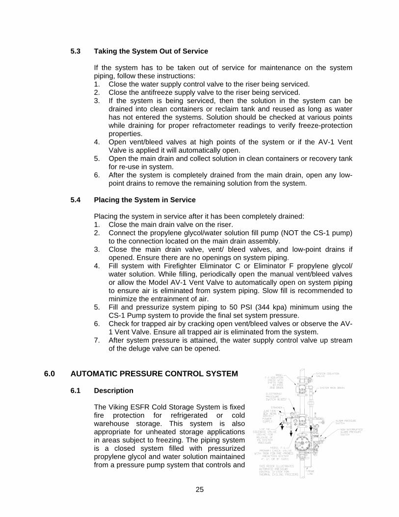
6.0 AUTOMATIC PRESSURE CONTROL SYSTEM 6.1 Description
The Viking ESFR Cold Storage System is fixed fire protection for refrigerated or cold warehouse storage. This system is also appropriate for unheated storage applications in areas subject to freezing. The piping system is a closed system filled with pressurized propylene glycol and water solution maintained from a pressure pump system that controls and
26
maintains the desired solution pressure. The ESFR Pre-Primed Single Interlocked Preaction Cold Storage System utilizes the Viking Deluge Valve and Easy RiserTM Check Valve with special trim to isolate the antifreeze in the system from the water supply. (NOTE: For previous Viking ESFR Cold Storage Systems, which utilized a wet system with the Model J-1 Alarm Check Valve, please contact the Viking Technical Services Department for details.) In cold storage areas where temperature can fluctuate, over-pressurization of the system can occur and cause the Pressure Relief Valve (PRV) to operate when the set point is reached. Normal operation of PRVs include operation at 90-105% of the set point and closing at 80% or above the set point. The Automatic Pressure Control System (APCS) is designed to maintain a safe operating pressure below the set point of the PRV and above the normal set pressure range of the CS-1 antifreeze pump system. In a warm-up situation, temperature fluctuations of the freezer area cause the pressure to also fluctuate. If the pressure increases over the set point of the PRV, the APCS is desired to prevent the PRV from operating, except for emergency situations where extended power loss may occur. The CS-1 Tank and Pump System is designed to maintain normal system supervisory pressure at 50 PSI (344 kpa) minimum for pre-primed preaction systems. The APCS includes an electronic digital pressure switch that includes a normally open SPST switch that is set to close at a pressure below the PRV set point and open above the shut off pressure of the sprinkler system control switch of the pump system. A normally closed solenoid valve is to be installed on the primary Easy RiserTM Check Valve at the ¼” connection provided. A 115 volt AC, 50 or 60 Hz. 15 to 20 ampere GFI protected electrical power supply is to be provided directly to the switch and solenoid valve. The power supply from switch to solenoid valve shall be wired through a non-interrupted alarm pressure switch. This will prevent the APCS valve from operating when system trips. As the pressure switch closing set point is reached due to system pressure increase upon warm-up of the freezer area, the switch will directly open the solenoid valve and release antifreeze solution back to the system reservoir tank. When the pressure reaches the lower setting, the switch will open, shutting off power to the solenoid valve and stopping flow of antifreeze. The APCS will NOT operate when the deluge valve has operated. NOTE: The Viking ESFR Cold Storage System shall be designed by qualified fire protection technicians, in conjunction with requirements of the Authorities Having Jurisdiction. These systems are designed to meet the UL Listing requirements described in Viking technical data for ESFR K25.2 Sprinkler VK510 for use with propylene glycol/water solution, and the standards of NFPA 13 or other organizations, and also with the provisions of governmental codes, ordinances, and standards where applicable.
6.2 Application
For thermal cycling freezers and coolers having closed non-compressible antifreeze systems, pressure can fluctuate drastically and possibly increase over
27
the PRV that protects the sprinklers at the ceiling at 175 PSI (1206kpa) maximum. The APCS is required in order to eliminate operation of the PRV. For warehouses with 40 ft (12,2 m) and 45 ft (13,7 m) ceiling heights, the head pressure increase could require more precise pressure control. The APCS allows for precise system control and prevents unwanted operation of the PRV. Normal operation of PRV is 90-105% of the set point. The closing pressure is only designed to 80% or greater of the set point. For pre-primed preaction systems, the supervisory antifreeze pressure is maintained at 50 PSI (344 kpa) minimum. The APCS is desired to protect the sprinklers and prevent the PRV from operating unless an emergency power loss situation occurs. The APCS maintains a safe system pressure in a precise range and prevents inadvertent operation of alarms and PRV in thermal cycling type freezers and cooler warehouses. If the freezer system is backed up with a secondary power supply, it is recommended that the APCS also be attached to this system for long power outage situations. If not, the PRV will possibly operate to automatically protect the system pressure in a warm-up situation.
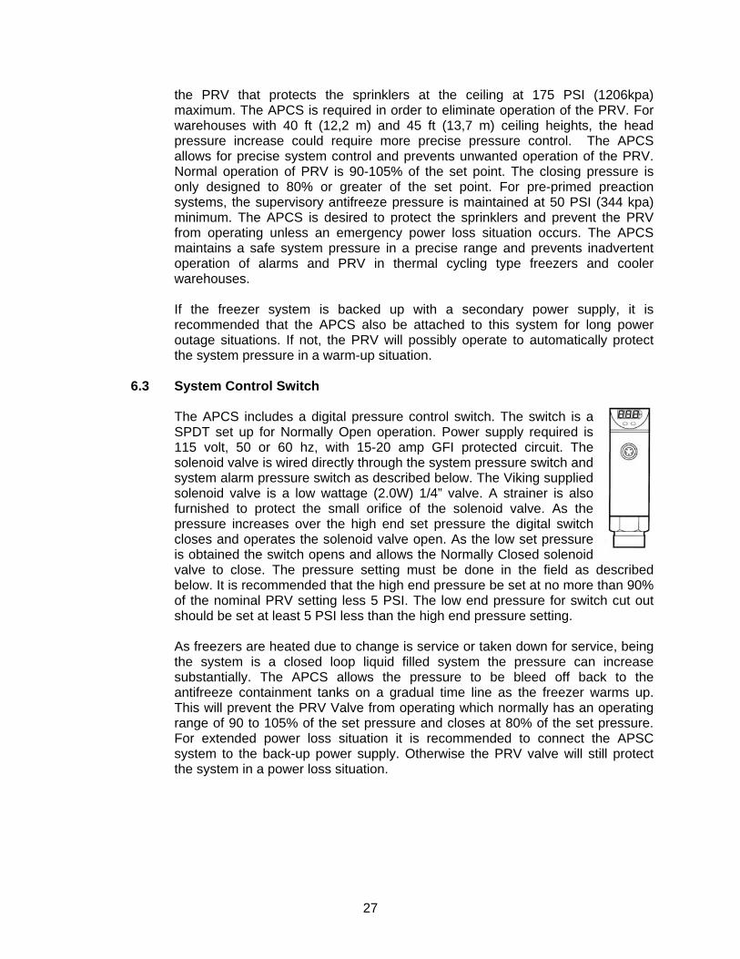
6.3 System Control Switch
The APCS includes a digital pressure control switch. The switch is a SPDT set up for Normally Open operation. Power supply required is 115 volt, 50 or 60 hz, with 15-20 amp GFI protected circuit. The solenoid valve is wired directly through the system pressure switch and system alarm pressure switch as described below. The Viking supplied solenoid valve is a low wattage (2.0W) 1/4” valve. A strainer is also furnished to protect the small orifice of the solenoid valve. As the pressure increases over the high end set pressure the digital switch closes and operates the solenoid valve open. As the low set pressure is obtained the switch opens and allows the Normally Closed solenoid valve to close. The pressure setting must be done in the field as described below. It is recommended that the high end pressure be set at no more than 90% of the nominal PRV setting less 5 PSI. The low end pressure for switch cut out should be set at least 5 PSI less than the high end pressure setting. As freezers are heated due to change is service or taken down for service, being the system is a closed loop liquid filled system the pressure can increase substantially. The APCS allows the pressure to be bleed off back to the antifreeze containment tanks on a gradual time line as the freezer warms up. This will prevent the PRV Valve from operating which normally has an operating range of 90 to 105% of the set pressure and closes at 80% of the set pressure. For extended power loss situation it is recommended to connect the APSC system to the back-up power supply. Otherwise the PRV valve will still protect the system in a power loss situation.
28
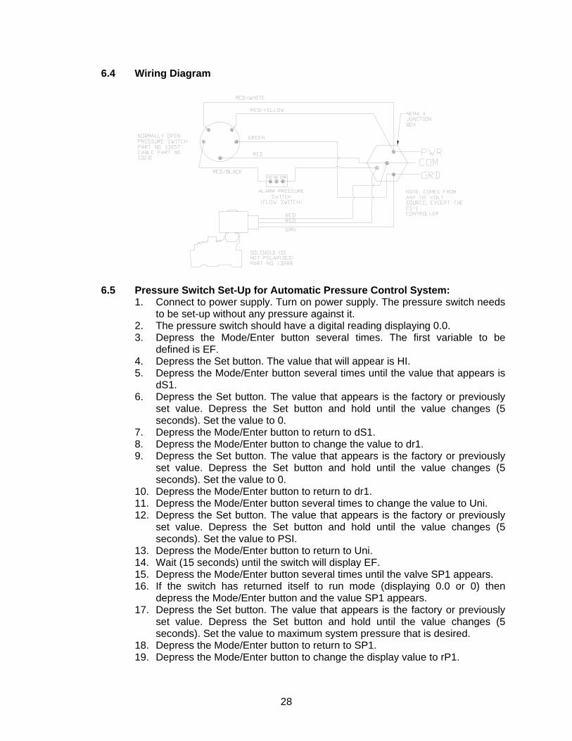
6.4 Wiring Diagram
6.5 Pressure Switch Set-Up for Automatic Pressure Control System:
1. Connect to power supply. Turn on power supply. The pressure switch needs to be set-up without any pressure against it.
2. The pressure switch should have a digital reading displaying 0.0. 3. Depress the Mode/Enter button several times. The first variable to be
defined is EF. 4. Depress the Set button. The value that will appear is HI. 5. Depress the Mode/Enter button several times until the value that appears is
dS1. 6. Depress the Set button. The value that appears is the factory or previously
set value. Depress the Set button and hold until the value changes (5 seconds). Set the value to 0.
7. Depress the Mode/Enter button to return to dS1. 8. Depress the Mode/Enter button to change the value to dr1. 9. Depress the Set button. The value that appears is the factory or previously
set value. Depress the Set button and hold until the value changes (5 seconds). Set the value to 0.
10. Depress the Mode/Enter button to return to dr1. 11. Depress the Mode/Enter button several times to change the value to Uni. 12. Depress the Set button. The value that appears is the factory or previously
set value. Depress the Set button and hold until the value changes (5 seconds). Set the value to PSI.
13. Depress the Mode/Enter button to return to Uni. 14. Wait (15 seconds) until the switch will display EF. 15. Depress the Mode/Enter button several times until the valve SP1 appears. 16. If the switch has returned itself to run mode (displaying 0.0 or 0) then
depress the Mode/Enter button and the value SP1 appears. 17. Depress the Set button. The value that appears is the factory or previously
set value. Depress the Set button and hold until the value changes (5 seconds). Set the value to maximum system pressure that is desired.
18. Depress the Mode/Enter button to return to SP1. 19. Depress the Mode/Enter button to change the display value to rP1.
29
20. Depress the Set button. The value that appears is the factory or previously set value. Depress the Set button and hold until the value changes (5 seconds). Set the value to minimum system pressure that is desired.
21. Depress the Mode/Enter button to return to rP1. 22. Depress the Mode/Enter button to change the display value to OU1. 23. Depress the Set button. The value that appears is the factory or previously
set value. Depress the Set button and hold until the value changes (5 seconds). Set the value to Hno.
24. Depress the Mode/Enter button to return to OU1. 25. Wait (15 seconds) and the switch will return to normal operation mode. 26. The switch is now properly set for operation. 27. Other values that may be set or reviewed.
a. H1 and LO can be set at desired value. b. COF should only be adjusted if the pressure reading is absolutely
determined to be inaccurate. c. CAr should only be used if there is a value in COF. 6.5 DAP should always be set at 0 to ensure that the system shuts down
the solenoid as soon as the pressure is obtained.
DiS should be set at d1, d2, or d3.
7.0 CS-1 ANTIFREEZE PUMP SYSTEM
ISOLATION VALVE SYSTEM(S)CONNECTION(S)
PUMP
65 OR 160
CONTROLPANEL
LIQUID SUPPLY
GALLON TANK
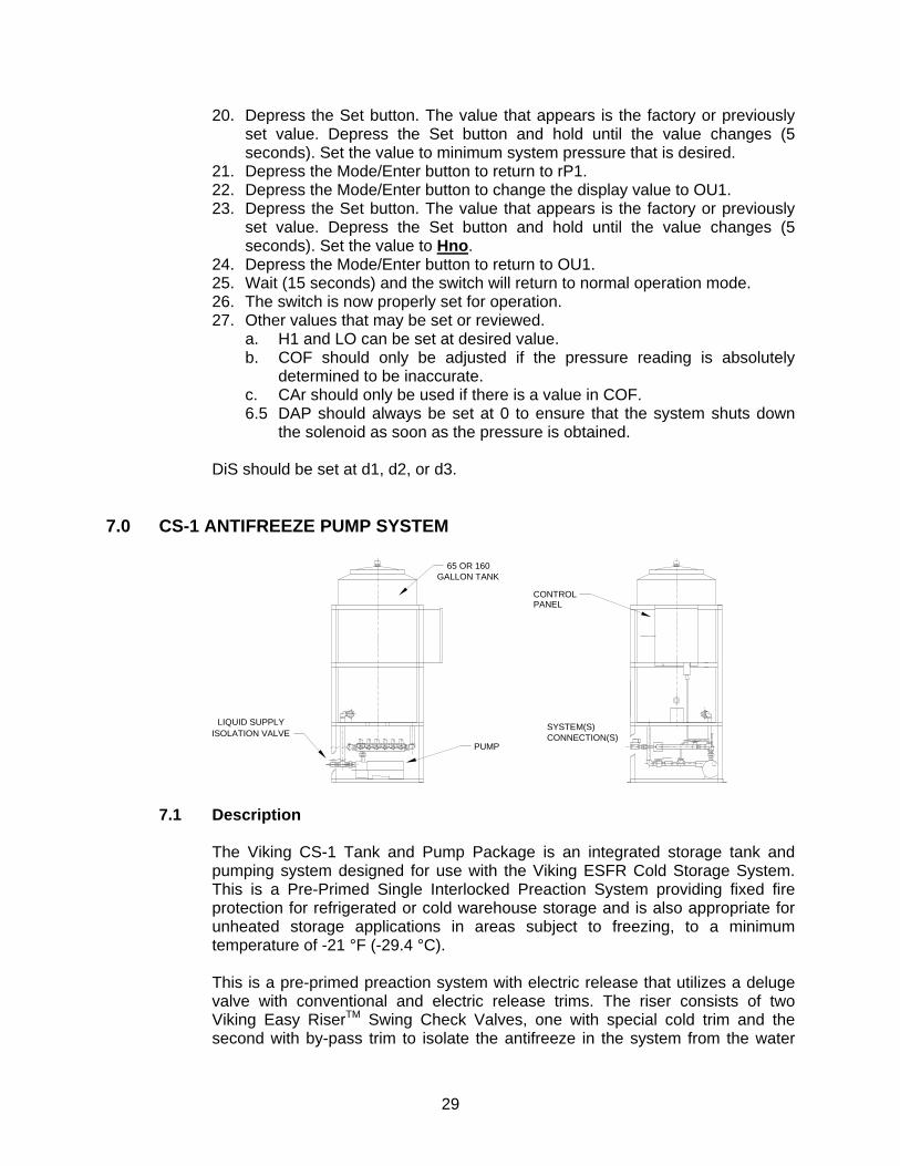
7.1 Description
The Viking CS-1 Tank and Pump Package is an integrated storage tank and pumping system designed for use with the Viking ESFR Cold Storage System. This is a Pre-Primed Single Interlocked Preaction System providing fixed fire protection for refrigerated or cold warehouse storage and is also appropriate for unheated storage applications in areas subject to freezing, to a minimum temperature of -21 °F (-29.4 °C). This is a pre-primed preaction system with electric release that utilizes a deluge valve with conventional and electric release trims. The riser consists of two Viking Easy RiserTM Swing Check Valves, one with special cold trim and the second with by-pass trim to isolate the antifreeze in the system from the water
30
supply. The tank and pump system automatically maintains the supervisory solution pressure in the piping above the check valves, until the detection system is activated. When the detection system is activated, the deluge valve is operated from the system releasing control panel. In the event of a fire condition, the detection system operates the deluge valve and pressurizes the system with the design discharge water pressure. The system pressure control switch is wired through the alarm pressure switch located on the deluge valve. In a fire condition, the CS-1 antifreeze pump unit keeps the supply solenoid valve closed that is supplying the operated riser system. In a situation where a sprinkler opens, breaks off, or pipe ruptures, causing a low pressure supervisory condition without a fire condition, the low pressure supervisory switch located on the primary check valve will provide an alarm. In this case, the antifreeze supply valve on the alarmed riser must be manually shut off. The pump uses antifreeze in the storage tank to maintain system pressure and make up for minor system leaks. The system is designed to accept up to 50% propylene glycol and water premix solution. It is recommended that Viking certified premix be used. Do not mix different antifreeze solutions within the system. WARNING: Motors, electrical equipment, and controls can cause electrical arcs that will ignite a flammable gas or vapor. Never operate or repair in or near a flammable gas or vapor. Never store flammable liquids or gases near the unit. SAFETY: This equipment is designed to be safe in the use for which it was planned, provided it is installed, started up, operated, and maintained in accordance with the instructions in this manual. Therefore, all personnel who install, use, or maintain the equipment must understand this manual. The unit contains electrical components that operate at line voltage and moving parts. Before working on the unit, isolate and lock it out from the electrical supply. All maintenance operations must be performed by qualified persons who have knowledge in the necessary precautions. NOTE: The Viking ESFR Cold Storage System shall be designed by qualified fire protection technicians, in conjunction with requirements of the Authorities Having Jurisdiction. These systems are designed to meet the UL Listing requirements described in Viking technical data for ESFR K25.2 Sprinkler VK510 for use with propylene glycol/water solution, and the standards of NFPA 13 or other organizations, and also with the provisions of governmental codes, ordinances, and standards where applicable.
7.2 Operating Principle
The tank and pump system maintains antifreeze in sprinkler system piping at desired supervisory pressure 50 PSI (344 kpa) minimum recommended pressure. A pressure switch on the unit senses the CS-1’s discharge manifold pressure and turns the pump on as the unit pressure drops to a preset pressure, and then stops the pump as unit pressure rises to a higher preset pressure. A level switch mounted in the storage tank opens when the liquid level is low. When the level switch opens, pump operation is inhibited and a set of dry contacts changes state for the user’s supervisory system. Terminals 21, 22, and 23 are for connection of low alarm devices. Also, the primary check valve
31
includes a low-pressure alarm switch that indicates a loss of supervisory pressure and requires a manual shutoff of the antifreeze supply valve. Up to six individual risers are connected to the CS-1 Tank and Pump System through normally closed solenoid valves. The supervisory pressure switch and flow alarm switch for each system are connected on site to the CS-1 system control. As system supervisory pressure drops, the corresponding solenoid valve opens, allowing flow from the CS-1 system to that system. When system pressure reaches the system set point, the system pressure switch opens and the CS-1 control closes that solenoid valve. In the case of flow due to a system operation, the normally closed contacts of that system’s flow alarm pressure switch open, and the CS-1 control prevents that system’s solenoid valve from opening, regardless of system pressure. A suitable portable pump can be utilized to fill the system to the static water pressure. (The CS-1 pump can be used for filling the system initially at 15 GPM (56 l/min) to 100 ft. head pressure or system static pressure, however, it is a less efficient pump for filling the system because of the duration of time required to do so. To fill the system, the CS-1 is connected to the antifreeze supply. The system to be filled is selected using two toggle switches on the CS-1 control enclosure. Antifreeze from the supply is pumped to the system piping. Pump operation is manually controlled during the fill process. The CS-1 pump is to be utilized to bring the solution to maintenance pressure, [normally 50 PSI (344 kPa) pressure] at the primary check valve and is designed to maintain system pressure once the system is initially filled. Two modes of electrical control are available. Manual operation allows the user to operate the pump motor by means of a switch regardless of the electrical controls status. Automatic operation uses the unit’s pressure switch to operate the pump based unit pressure. Flow to each riser is controlled by that system’s pressure switch and flow alarm switch. In “Automatic” mode, pump operation is limited to six times per hour. Also, pump operation is inhibited at low liquid level in the tank. WARNING: The CS-1 system must be attended at all times in Manual mode. The pump can operate without liquid in Manual mode, which will damage the pump. Running the CS-1 without fluid in Manual mode voids the warranty. This pump is not self- priming. The storage tank is opaque to allow visual indication of the antifreeze leveling. A Y-Strainer is included on the pump suction line. A locking valve is included on discharge line. Lock in the open position. This valve is used to isolate the antifreeze storage tank for maintenance. A check valve in pump discharge piping prevents antifreeze backflow from the system, which would damage the pump. An adjustable pressure relief valve is included to protect the pump discharge piping. This relief valve must be set at 10 PSI (68,9 kPa) above the pump system pressure switch. All components of the pump unit are compatible with the antifreeze solution and rated to a maximum pressure of 225 PSI (1 551 kPa).
32
7.3 CS-1 Control Scheme
7.3.1 General The CS-1 Tank and Pump System maintains pressure for up to six risers with individual control to each riser. A two-way normally closed solenoid valve is connected to each riser. The pressure maintenance switch on each riser controls the corresponding solenoid valve. At a low riser pressure condition, the solenoid opens, allowing flow from the CS-1 to that riser. In the case of operation of a riser due to flow from a sprinkler, the riser’s alarm pressure switch sends a signal to the CS-1 control panel, and keeps the corresponding solenoid valve from opening. A drop in pressure operates the CS-1 pump. Pump operation is controlled by the pressure switch and level switch mounted on the CS-1. There are two normal operating modes for the CS-1 Tank and Pump Package, “Manual” and “Automatic”. The Manual mode is used for filling the unit’s tank and filling systems through the CS-1, using the unit’s pump. The Automatic mode maintains system(s) pressure(s) after filling is complete.
7.3.2 Operation
The pressure switch mounted on the CS-1 controls pump operation. When the pressure at the CS-1 drops, the pump will turn on until the pressure at the CS-1 rises above a set level. In “Automatic” mode, pump operation is inhibited if the level of liquid in the unit’s storage tank drops below the level switch height. In “Manual” mode, the pump operates when CS-1 pressure drops, and tank level is satisfied, and a system valve is selected, and that system pressure is not met, and there is no alarm condition. The pump can also fill the tank in Manual mode. For tank filling, the level switch position is not used and the operator must start and stop the pump, using the “Hand” position of the Hand-Off-Auto Switch on the control panel. (Note: In order to operate in manual mode, all pressure switches must be properly connected.) In Automatic mode, there is a 10-minute time delay between pump operations. After the 10-minute delay, the pump operates if the CS-1 pressure drops and tank fluid level is above the level switch height. When the pump shuts off, the 10-minute timer starts again and the pump will not operate until 10 minutes is complete.
7.3.3 System Solenoid Valve Operation
Each system (riser) pressure switch and alarm pressure switch contacts are connected in series to one input on the PLC. The system pressure switch closes on falling pressure. The alarm pressure switch normally closed contacts are used and open in the alarm condition.
33
In Automatic mode, each system solenoid valve opens if its system pressure drops to a low-pressure condition and there is no alarm pressure signal. In Manual mode, each system valve is selected by means of two selector switches and the solenoid valve opens as long as system pressure is below the set-point value and there is no system alarm.
7.3.4 Level Switch Relay Coil Operation
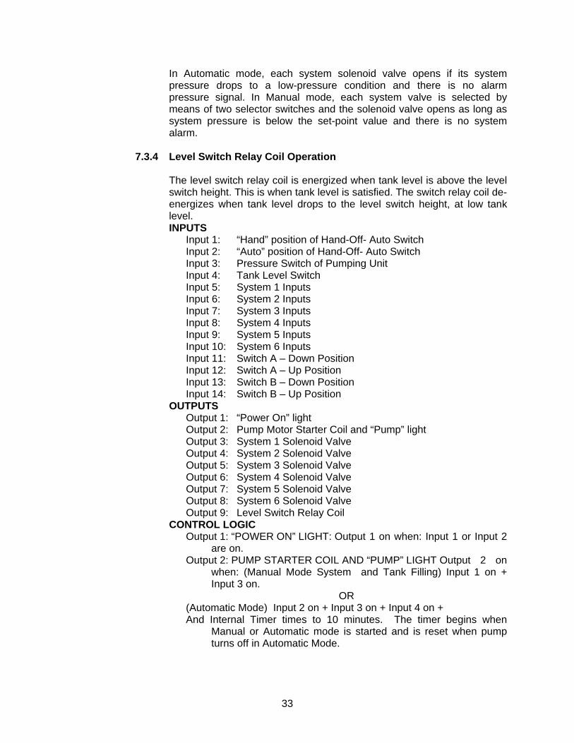
The level switch relay coil is energized when tank level is above the level switch height. This is when tank level is satisfied. The switch relay coil de-energizes when tank level drops to the level switch height, at low tank level. INPUTS
Input 1: “Hand” position of Hand-Off- Auto Switch Input 2: “Auto” position of Hand-Off- Auto Switch Input 3: Pressure Switch of Pumping Unit Input 4: Tank Level Switch Input 5: System 1 Inputs Input 6: System 2 Inputs Input 7: System 3 Inputs Input 8: System 4 Inputs Input 9: System 5 Inputs Input 10: System 6 Inputs Input 11: Switch A – Down Position Input 12: Switch A – Up Position Input 13: Switch B – Down Position Input 14: Switch B – Up Position
OUTPUTS Output 1: “Power On” light Output 2: Pump Motor Starter Coil and “Pump” light Output 3: System 1 Solenoid Valve Output 4: System 2 Solenoid Valve Output 5: System 3 Solenoid Valve Output 6: System 4 Solenoid Valve Output 7: System 5 Solenoid Valve Output 8: System 6 Solenoid Valve Output 9: Level Switch Relay Coil
CONTROL LOGIC Output 1: “POWER ON” LIGHT: Output 1 on when: Input 1 or Input 2
are on. Output 2: PUMP STARTER COIL AND “PUMP” LIGHT Output 2 on
when: (Manual Mode System and Tank Filling) Input 1 on + Input 3 on.
OR (Automatic Mode) Input 2 on + Input 3 on + Input 4 on + And Internal Timer times to 10 minutes. The timer begins when
Manual or Automatic mode is started and is reset when pump turns off in Automatic Mode.
34
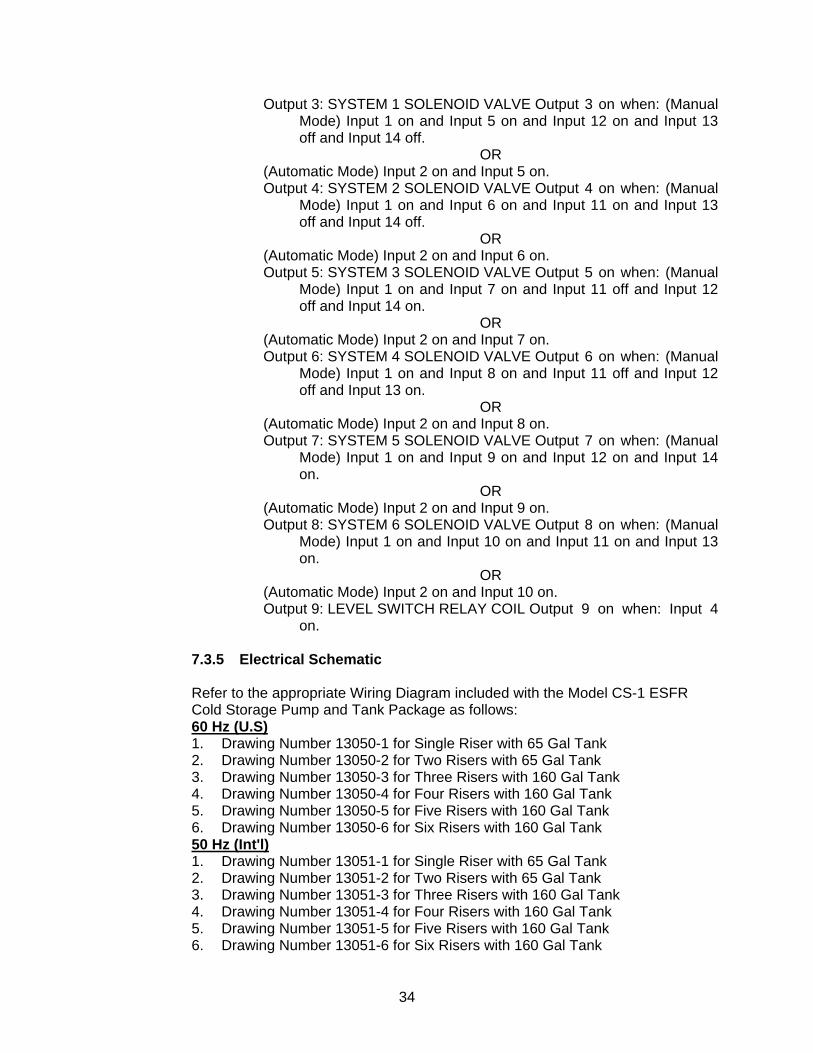
Output 3: SYSTEM 1 SOLENOID VALVE Output 3 on when: (Manual Mode) Input 1 on and Input 5 on and Input 12 on and Input 13 off and Input 14 off.
OR (Automatic Mode) Input 2 on and Input 5 on. Output 4: SYSTEM 2 SOLENOID VALVE Output 4 on when: (Manual
Mode) Input 1 on and Input 6 on and Input 11 on and Input 13 off and Input 14 off.
OR (Automatic Mode) Input 2 on and Input 6 on. Output 5: SYSTEM 3 SOLENOID VALVE Output 5 on when: (Manual
Mode) Input 1 on and Input 7 on and Input 11 off and Input 12 off and Input 14 on.
OR (Automatic Mode) Input 2 on and Input 7 on. Output 6: SYSTEM 4 SOLENOID VALVE Output 6 on when: (Manual
Mode) Input 1 on and Input 8 on and Input 11 off and Input 12 off and Input 13 on.
OR (Automatic Mode) Input 2 on and Input 8 on. Output 7: SYSTEM 5 SOLENOID VALVE Output 7 on when: (Manual
Mode) Input 1 on and Input 9 on and Input 12 on and Input 14 on.
OR (Automatic Mode) Input 2 on and Input 9 on. Output 8: SYSTEM 6 SOLENOID VALVE Output 8 on when: (Manual
Mode) Input 1 on and Input 10 on and Input 11 on and Input 13 on.
OR (Automatic Mode) Input 2 on and Input 10 on. Output 9: LEVEL SWITCH RELAY COIL Output 9 on when: Input 4
on.
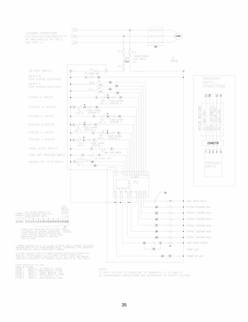
7.3.5 Electrical Schematic
Refer to the appropriate Wiring Diagram included with the Model CS-1 ESFR Cold Storage Pump and Tank Package as follows: 60 Hz (U.S) 1. Drawing Number 13050-1 for Single Riser with 65 Gal Tank 2. Drawing Number 13050-2 for Two Risers with 65 Gal Tank 3. Drawing Number 13050-3 for Three Risers with 160 Gal Tank 4. Drawing Number 13050-4 for Four Risers with 160 Gal Tank 5. Drawing Number 13050-5 for Five Risers with 160 Gal Tank 6. Drawing Number 13050-6 for Six Risers with 160 Gal Tank 50 Hz (Int'l) 1. Drawing Number 13051-1 for Single Riser with 65 Gal Tank 2. Drawing Number 13051-2 for Two Risers with 65 Gal Tank 3. Drawing Number 13051-3 for Three Risers with 160 Gal Tank 4. Drawing Number 13051-4 for Four Risers with 160 Gal Tank 5. Drawing Number 13051-5 for Five Risers with 160 Gal Tank 6. Drawing Number 13051-6 for Six Risers with 160 Gal Tank
35
36
7.4 Installation
7.4.1 Receiving And Inspection
When the equipment is received, immediately inspect it for shortages and visible and concealed damage. If the equipment has been damaged in shipment or shortages are noticed, immediately notify the carrier and file a claim.
7.4.2 Handling
Move the CS-1 on the shipping pallet as close to the final location as possible. Always lift the unit from underneath. Never lift the unit when it is full of liquid. Personal injury and/or equipment damage could result. Ensure that all equipment used to lift the CS-1 is capable of lifting the weight. Nylon straps and soft rigging devices should be used whenever possible to protect the components and finish. If the unit is being transported overhead, be sure that all personnel are alerted and safety procedures are followed.
7.4.3 Location
WARNING! DO NOT INSTALL THE CS-1 IN AN ENVIRONMENT OF CORROSIVE CHEMICALS, EXPLOSIVE GASES, POISONOUS GASES, STEAM HEAT, AREAS OF HIGH AMBIENT CONDITIONS, OR EXTREME DUST AND DIRT. Install the CS-1 indoors in a clean, dry, non-corrosive environment. This equipment is not to be installed outdoors exposed to the weather. Position the CS-1 in an upright position on a solid, level, vibration-free surface capable of supporting the weight of the unit and liquid in the tank. Bolt the unit to the floor using the bolt holes provided in the frame. Always shim the unit level before bolting it to the floor. Install the CS-1 in a protected, well-ventilated area where the ambient temperatures are between 40 °F and 100 °F (4 and °C). Locate the CS-1 to allow access to supply and discharge connections. Clearance around the unit should be at least 24“ on all sides for maintenance. Some jurisdictions require specific clearances around equipment. Check with all local Authorities to ensure compliance with applicable state, local, and national codes.
7.4.4 Piping And Connections
A slight downward slope from the supply container to the CS-1 supply valve connection is recommended to maintain positive head on the pump inlet. Always use a backup wrench when making piping connections to avoid damage to the unit’s piping.
37
Size piping between the CS-1 and the system to minimize pressure drop. Too small of a line size restricts pump flow, lowering capacity when filling the system. Lower capacity while filling the system requires longer fill times. The sprinkler system must contain air vent/bleed valves at all local high points. These are used to let air out of the system while filling with antifreeze. Consult the system instructions for specifics. Individual check valves and isolation valves are required for each system. This allows system maintenance without disturbing other systems the CS-1 is connected to. Piping and/or hoses from the antifreeze supply containers to the unit should be sloped downhill slightly to provide positive head on the pump suction connection. These lines should be as large as possible and as short as possible to provide unrestricted flow to the pump while filling. A separate shut-off valve in the supply line is required. Unit piping is copper, brass and bronze. An aluminum manifold is included for mounting multiple system solenoids. Use dielectric unions to isolate copper piping from iron piping, if used, to reduce the possibility of electrolytic action on pipes and other components. All pipes should be de-burred and threaded to a proper depth and length before installation. Threads should be inspected for cleanliness and depth of cut. Good quality pipe compound should be used to ensure a good, leak tight fit of piping components. NOTE: Pipe must be supported separately from the CS-1. At no time should the CS-1 support the weight or load of the pipe. Acceptable pipe mounting devices would be unistrut supports anchored to walls, hangers suspended from ceilings, or pedestals mounted from the floor. Be sure all pipe installation conforms to all building & fire codes.
7.5 Electrical Connections
SERIOUS PERSONAL INJURY AND DAMAGE TO THE CS-1 COULD OCCUR IF IT IS CONNECTED TO A POWER SOURCE OTHER THAN THE VOLTAGE LISTED ON THE DATA TAG. THE MANUFACTURER IS NOT LIABLE FOR DAMAGE DUE TO IMPROPER WIRING, PROTECTION, OR ELECTRICAL SERVICE INSTALLATION. WHEN INSTALLING ELECTRICAL SERVICE TO THIS MACHINE, COMPLY WITH THE NATIONAL ELECTRIC CODE AS WELL AS STATE AND LOCAL BUILDING CODES. FAILURE TO INSTALL THE PROPER ELECTRICAL PROTECTION CAN RESULT IN PERSONAL INJURY, FIRE, EQUIPMENT DAMAGE, OR DEATH. THE MFR IS NOT RESPONSIBLE FOR DAMAGE OR INJURY CAUSED BY LACK OF OR IMPROPERLY INSTALLED ELECTRICAL PROTECTION. Electrical connection to the unit is made in the control enclosure. Connect appropriate supply power to the terminals provided. The supply wire must be of adequate size and no other equipment should be connected to the same circuit.
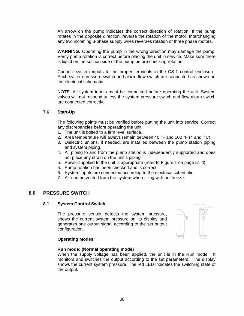
38
An arrow on the pump indicates the correct direction of rotation. If the pump rotates in the opposite direction, reverse the rotation of the motor. Interchanging any two incoming 3-phase supply wires reverses rotation of three phase motors. WARNING: Operating the pump in the wrong direction may damage the pump. Verify pump rotation is correct before placing the unit in service. Make sure there is liquid on the suction side of the pump before checking rotation. Connect system inputs to the proper terminals in the CS-1 control enclosure. Each system pressure switch and alarm flow switch are connected as shown on the electrical schematic. NOTE: All system inputs must be connected before operating the unit. System valves will not respond unless the system pressure switch and flow alarm switch are connected correctly.
7.6 Start-Up
The following points must be verified before putting the unit into service. Correct any discrepancies before operating the unit. 1. The unit is bolted to a firm level surface. 2. Area temperature will always remain between 40 °F and 100 °F (4 and °C). 3. Dielectric unions, if needed, are installed between the pump station piping
and system piping. 4. All piping to and from the pump station is independently supported and does
not place any strain on the unit’s piping. 5. Power supplied to the unit is appropriate (refer to Figure 1 on page 51 d). 5. Pump rotation has been checked and is correct. 6. System inputs are connected according to the electrical schematic. 7. Air can be vented from the system when filling with antifreeze.
8.0 PRESSURE SWITCH
8.1 System Control Switch The pressure sensor detects the system pressure, shows the current system pressure on its display and generates one output signal according to the set output configuration. Operating Modes Run mode: (Normal operating mode) When the supply voltage has been applied, the unit is in the Run mode. It monitors and switches the output according to the set parameters. The display shows the current system pressure. The red LED indicates the switching state of the output.
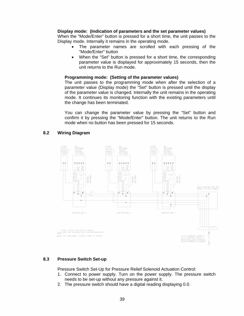
39
Display mode: (Indication of parameters and the set parameter values) When the “Mode/Enter” button is pressed for a short time, the unit passes to the Display mode. Internally it remains in the operating mode.
• The parameter names are scrolled with each pressing of the “Mode/Enter” button
• When the “Set” button is pressed for a short time, the corresponding parameter value is displayed for approximately 15 seconds, then the unit returns to the Run mode.
Programming mode: (Setting of the parameter values) The unit passes to the programming mode when after the selection of a parameter value (Display mode) the “Set” button is pressed until the display of the parameter value is changed. Internally the unit remains in the operating mode. It continues its monitoring function with the existing parameters until the change has been terminated. You can change the parameter value by pressing the “Set” button and confirm it by pressing the “Mode/Enter” button. The unit returns to the Run mode when no button has been pressed for 15 seconds.
8.2 Wiring Diagram
____
8.3 Pressure Switch Set-up
Pressure Switch Set-Up for Pressure Relief Solenoid Actuation Control: 1. Connect to power supply. Turn on the power supply. The pressure switch
needs to be set-up without any pressure against it. 2. The pressure switch should have a digital reading displaying 0.0.
40
3. Depress the Mode/Enter button several times. The first variable to be defined is EF.
4. Depress the Set button. The value that will appear is HI. 5. Depress the Mode/Enter button several times until the value that appears is
dS1. 6. Depress the Set button. The value that appears is the factory or previously
set value. Depress the Set button and hold until the value changes (5 seconds). Set the value to 0.
7. Depress the Mode/Enter button to return to dS1. 8. Depress the Mode/Enter button to change the value to dr1. 9. Depress the Set button. The value that appears is the factory or previously
set value. Depress the Set button and hold until the value changes (5 seconds). Set the value to 0.
10. Depress the Mode/Enter button to return to dr1. 11. Depress the Mode/Enter button several times to change the value to Uni. 12. Depress the Set button. The value that appears is the factory or previously
set value. Depress the Set button and hold until the value changes (5 seconds). Set the value to PSI.
13. Depress the Mode/Enter button to return to Uni. 14. Wait (15 seconds) until the switch will display EF. 15. Depress the Mode/Enter button several times until the valve SP1 appears. 16. If the switch has returned itself to run mode (displaying 0.0 or 0) then depress
the Mode/Enter button and the value SP1 appears. 17. Depress the Set button. The value that appears is the factory or previously
set value. Depress the Set button and hold until the value changes (5 seconds). Set the value to maximum system pressure that is desired.
18. Depress the Mode/Enter button to return to SP1. 19. Depress the Mode/Enter button to change the display value to rP1. 20. Depress the Set button. The value that appears is the factory or previously
set value. Depress the Set button and hold until the value changes (5 seconds). Set the value to minimum system pressure that is desired.
21. Depress the Mode/Enter button to return to rP1. 22. Depress the Mode/Enter button to change the display value to OU1. 23. Depress the Set button. The value that appears is the factory or previously
set value. Depress the Set button and hold until the value changes (5 seconds). Set the value to Hnc.
24. Depress the Mode/Enter button to return to OU1. 25. Wait (15 seconds) and the switch will return to normal operation mode. 26. The switch is now properly set for operation. 27. Other values that may be set or reviewed.
a. H1 and LO can be set at desired value. b. COF should only be adjusted if the pressure reading is absolutely
determined to be inaccurate. c. CAr should only be used if there is a value in COF. d. DAP should always be set at 0 to ensure that the system shuts down the
solenoid as soon as the pressure is obtained.
DiS should be set at d1, d2, or d3.
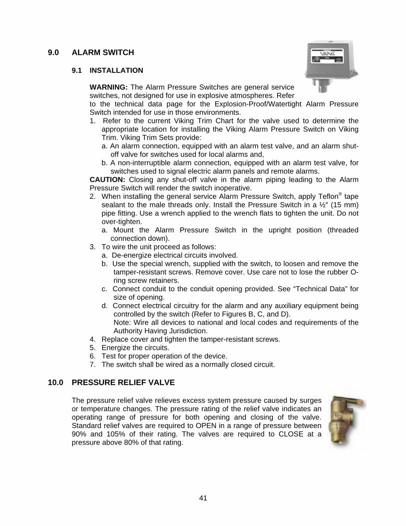
41
9.0 ALARM SWITCH
9.1 INSTALLATION WARNING: The Alarm Pressure Switches are general service switches, not designed for use in explosive atmospheres. Refer to the technical data page for the Explosion-Proof/Watertight Alarm Pressure Switch intended for use in those environments. 1. Refer to the current Viking Trim Chart for the valve used to determine the
appropriate location for installing the Viking Alarm Pressure Switch on Viking Trim. Viking Trim Sets provide: a. An alarm connection, equipped with an alarm test valve, and an alarm shut-
off valve for switches used for local alarms and, b. A non-interruptible alarm connection, equipped with an alarm test valve, for
switches used to signal electric alarm panels and remote alarms. CAUTION: Closing any shut-off valve in the alarm piping leading to the Alarm Pressure Switch will render the switch inoperative. 2. When installing the general service Alarm Pressure Switch, apply Teflon® tape
sealant to the male threads only. Install the Pressure Switch in a ½" (15 mm) pipe fitting. Use a wrench applied to the wrench flats to tighten the unit. Do not over-tighten. a. Mount the Alarm Pressure Switch in the upright position (threaded
connection down). 3. To wire the unit proceed as follows:
a. De-energize electrical circuits involved. b. Use the special wrench, supplied with the switch, to loosen and remove the
tamper-resistant screws. Remove cover. Use care not to lose the rubber O-ring screw retainers.
c. Connect conduit to the conduit opening provided. See “Technical Data” for size of opening.
d. Connect electrical circuitry for the alarm and any auxiliary equipment being controlled by the switch (Refer to Figures B, C, and D). Note: Wire all devices to national and local codes and requirements of the Authority Having Jurisdiction.
4. Replace cover and tighten the tamper-resistant screws. 5. Energize the circuits. 6. Test for proper operation of the device. 7. The switch shall be wired as a normally closed circuit.
10.0 PRESSURE RELIEF VALVE
The pressure relief valve relieves excess system pressure caused by surges or temperature changes. The pressure rating of the relief valve indicates an operating range of pressure for both opening and closing of the valve. Standard relief valves are required to OPEN in a range of pressure between 90% and 105% of their rating. The valves are required to CLOSE at a pressure above 80% of that rating.
42
The relief valve should be installed where it is easily accessible for maintenance. Care should be taken that the relief valve CANNOT be isolated from the system when the system is operational. A relief valve should never have a shutoff valve or a plug downstream of its outlet. The PRV MUST be piped to an adequate drain. Operation will discharge antifreeze or water from its outlet. See Section 19.0 System Parts List for listing of part numbers and pressures available.
11.0 ANVIL COUPLINGS, SEALS & LUBE
11.1 Couplings
The C-4 rigid coupling is design for rigid piping applications. The C-4 is specially designed to provide a rigid, locked-in pipe connection to meet the specific demands of rigid design steel pipe. Housing: Ductile iron conforming to ASTM A-536, Grade 65-45-12 ANSI Bolts and Heavy Hex Nuts: Heat treated, oval neck track head bolts confirming to ASTM A-183 Grade 2with a minimum tensile strength of 110,000 psi and heavy hex nuts of carbon steel conforming to ASTMA-563 Grade A or Grade B, or J995 Grade 2. Bolts and nuts are provided zinc electroplated as standard. Metric Bolts and Heavy Hex Nuts: Heat treated, zinc electroplated oval-neck track head bolts made of carbon steel with mechanical properties per ISO 898-1 Class 8.8 Hex nuts and bolts are zinc electroplated followed by a yellow chromate dip. Gaskets: Grade “E” EPDM. NSF-61 Certified. -30 °F to 230 °F (Service Temperature Range) (40 °C to 110°C) Recommended for water service, diluted acids, alkalys solutions, oil-free air and many chemical services. Xtreme™ Lubricant is required for freezer applications.
11.2 Flush Gap Gaskets
Flush gap gaskets are designed to prohibit contamination from building up in the gasket cavity. The centering rib fits flush over the gap between the two pipe ends thus closing off the gasket cavity. Not recommended for temperatures above 160 °F.
11.3 Lubricant
GRUVLOK Xtreme Lubricant has been developed for use with Gruvlok couplings in services where improved lubrication is beneficial. This lubricant has an operating temperature range from -65 °F to 400°F, well exceeding the temperature range of Gruvlok gaskets. This lubricant is waterproof, thereby eliminating water wash-out and it will not dry out in the absence of water. There are five primary applications where the Xtreme Lubricant will provide increased benefits: low temperature applications (below -20 °F), high temperature applications (above 180 °F), applications where increased pipe joint flexibility is needed, lubrication of gaskets in copper systems, and for the lubrication of gaskets on HDPE couplings. Since it is formulated from a non-hydro carbon
43
base, it can be used with EPDM, Nitrile and Fluoroelastomer gasket materials. It is not to be used with silicone gaskets. • In low temperature applications the gasket will shrink, thereby lowering the
sealing force on the gasket sealing lips. The temperature change will also force the gasket to slightly re-position itself. This will cause pipe end sealing surfaces, with small cuts or damage, to become more susceptible to leakage. Gruvlok Xtreme Lubricant will maintain it’s lubricating properties at lower temperatures allowing a properly lubricated pipe end and gasket (assembly) to re-position itself during temperature cycles.
• For high-temperature service and copper systems, it is required that the gasket
be lubricated not only on the outside, as with the normal installation of a Gruvlok gasket, but also on the inside. Lubrication on the inside of the gasket is easily accomplished by turning the gasket inside out and applying the lubricant. Gruvlok Xtreme Lubricant will maintain it’s lubricating properties at higher temperatures, allowing a properly lubricated pipe end and gasket assembly to re-position itself during temperature cycles. Lubrication of the pipe end and gasket will help the gasket to adjust into the proper sealing position during temperature cycles. The lubricant on the interior of the gasket will act to improve the chemical resistance of the gasket material by providing a thin lubricant barrier between the piping system fluid and the gasket surface. This is particularly important at higher temperatures where oxidizing agents in the piping system become more aggressive. However, gasket chemical compatibility must still be considered.
• The Gruvlok Xtreme Lubricant has been formulated from low viscosity, non-
petroleum based oils to ease spreading of the lubricant. In applications where pipe movement is expected, proper lubrication of the gasket’s exterior assists the gasket into the proper sealing position as pipe system movement occurs. This lubricating film enhances our flexible coupling gasket’s ability to compensate for axial, transverse and rotational pipe movements.
• Gruvlok Xtreme Lubricant is the only Gruvlok lubricant that is to be used with
Gruvlok couplings and gaskets in HDPE and copper piping systems. It’s low temperature capability and lubricity ensure a highly reliable connection. Gruvlok Xtreme Lubricant is a Teflon fortified white, tasteless and odorless grease made from Silicone Oil and other ingredients that are safe to ingest. It is sanctioned by the FDA under C.F.R. 21.172.878 & 21.177.1550 (Incidental Food Contact).
Caution: Silicone based lubricants are not allowed in some facilities. ®Teflon is a registered trademark of Dupont.
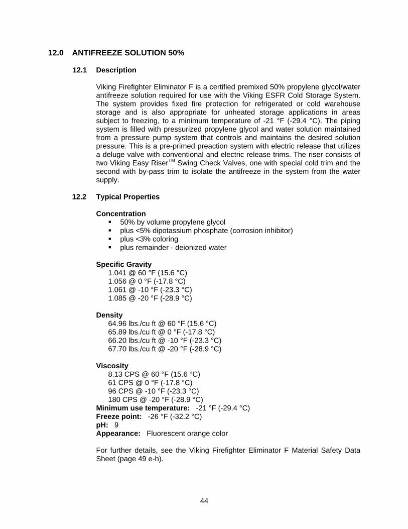
44
12.0 ANTIFREEZE SOLUTION 50%
12.1 Description
Viking Firefighter Eliminator F is a certified premixed 50% propylene glycol/water antifreeze solution required for use with the Viking ESFR Cold Storage System. The system provides fixed fire protection for refrigerated or cold warehouse storage and is also appropriate for unheated storage applications in areas subject to freezing, to a minimum temperature of -21 °F (-29.4 °C). The piping system is filled with pressurized propylene glycol and water solution maintained from a pressure pump system that controls and maintains the desired solution pressure. This is a pre-primed preaction system with electric release that utilizes a deluge valve with conventional and electric release trims. The riser consists of two Viking Easy RiserTM Swing Check Valves, one with special cold trim and the second with by-pass trim to isolate the antifreeze in the system from the water supply.
12.2 Typical Properties
Concentration 50% by volume propylene glycol plus <5% dipotassium phosphate (corrosion inhibitor) plus <3% coloring plus remainder - deionized water
Specific Gravity
1.041 @ 60 °F (15.6 °C) 1.056 @ 0 °F (-17.8 °C) 1.061 @ -10 °F (-23.3 °C) 1.085 @ -20 °F (-28.9 °C)
Density 64.96 lbs./cu ft @ 60 °F (15.6 °C) 65.89 lbs./cu ft @ 0 °F (-17.8 °C) 66.20 lbs./cu ft @ -10 °F (-23.3 °C) 67.70 lbs./cu ft @ -20 °F (-28.9 °C)
Viscosity 8.13 CPS @ 60 °F (15.6 °C) 61 CPS @ 0 °F (-17.8 °C) 96 CPS @ -10 °F (-23.3 °C) 180 CPS @ -20 °F (-28.9 °C)
Minimum use temperature: -21 °F (-29.4 °C) Freeze point: -26 °F (-32.2 °C) pH: 9 Appearance: Fluorescent orange color For further details, see the Viking Firefighter Eliminator F Material Safety Data Sheet (page 49 e-h).
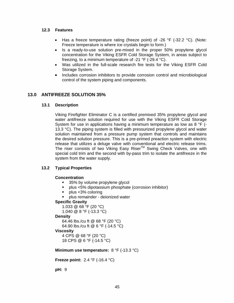
45
12.3 Features
• Has a freeze temperature rating (freeze point) of -26 °F (-32.2 °C). (Note: Freeze temperature is where ice crystals begin to form.)
• Is a ready-to-use solution pre-mixed in the proper 50% propylene glycol concentration for the Viking ESFR Cold Storage System, in areas subject to freezing, to a minimum temperature of -21 °F (-29.4 °C).
• Was utilized in the full-scale research fire tests for the Viking ESFR Cold Storage System.
• Includes corrosion inhibitors to provide corrosion control and microbiological control of the system piping and components.
13.0 ANTIFREEZE SOLUTION 35%
13.1 Description
Viking Firefighter Eliminator C is a certified premixed 35% propylene glycol and water antifreeze solution required for use with the Viking ESFR Cold Storage System for use in applications having a minimum temperature as low as 8 °F (-13.3 °C). The piping system is filled with pressurized propylene glycol and water solution maintained from a pressure pump system that controls and maintains the desired solution pressure. This is a pre-primed preaction system with electric release that utilizes a deluge valve with conventional and electric release trims. The riser consists of two Viking Easy RiserTM Swing Check Valves, one with special cold trim and the second with by-pass trim to isolate the antifreeze in the system from the water supply.
13.2 Typical Properties
Concentration 35% by volume propylene glycol plus <5% dipotassium phosphate (corrosion inhibitor) plus <3% coloring plus remainder - deionized water
Specific Gravity 1.033 @ 68 °F (20 °C) 1.040 @ 8 °F (-13.3 °C)
Density 64.46 lbs./cu ft @ 68 °F (20 °C) 64.90 lbs./cu ft @ 6 °F (-14.5 °C)
Viscosity 4 CPS @ 68 °F (20 °C) 18 CPS @ 6 °F (-14.5 °C)
Minimum use temperature: 8 °F (-13.3 °C) Freeze point: 2.4 °F (-16.4 °C) pH: 9
46
Appearance: Fluorescent green color
For further details, see the Viking Firefighter Eliminator C Material Safety Data Sheet (page 50 e-h).
13.3 Features
• Has a freeze temperature rating (freeze point) of 2.4 °F (-16.4 °C). (Note: Freeze temperature is where ice crystals begin to form.)
• Is a ready-to-use solution pre-mixed in the proper 35% concentration of propylene glycol for the Viking ESFR Cold Storage System for use in areas subject to a minimum temperature as low as 8 °F (-13.3 °C).
• Was utilized in the full-scale research fire tests for the Viking ESFR Cold Storage System.
• Includes corrosion inhibitors to provide corrosion control and microbiological control of the system piping and components.
14.0 HEAT TRACE SYSTEM & INSULATION 14.1 Insulation of Riser Main
The riser and supply main coming from the freezer area that is maintained at the desired freezing temperature to the valve riser system, which is in a heated area will produce frosting on the exterior of the piping. Hydronic Convective heat transfer takes place in this type system in which cold antifreeze is circulated from the freezer toward the warmer piping area. This circulation allows the riser pipe to maintain a very cold temperature as supplied from the freezer area. The moisture in the heated area air will cause formation of liquid on the pipe surface. Due to the freezing temperature of the antifreeze Frost will form on the exterior of the supply piping. In order to prevent the moisture from building on the pipe exterior surface, fiberglass Thermal insulation with a polyester vapor barrier wrap is required to be applied to the supply piping from the freezer wall to the bottom of the Isolation check valve. In severe cases the insulation may require heat tracing under the insulation in order to maintain a higher temperature at the pipe exterior surface under the insulation.
14.2 Insulation of Isolation Check Valve
Viking has available a preformed insulation cover that allows for trim piping connections and removal for valve maintenance. These are custom manufactured for each check valve size.
14.3 Heat Trace System
Viking has available through our SupplyNet locations a self regulating heat trace system when required. The temperature control unit provides automatic control of the set pipe surface temperature. The length of heat trace wire and pitch of wrap on the pipe is determined by the given temperature conditions. Sizing of wire length and wattage is available on request.
47
15.0 SYSTEM FILL PROCEDURE
15.1 Filling The Reservoir Tank
The CS-1 has been designed to fill the reservoir tank using either of two methods: gravity fill or pumped fill. NOTE: This is not a self-priming pump. Manual prime or fill the reservoir for prime. NOTE: Never leave the unit unattended when filling the system or tank. Running the pump dry, without liquid, will damage pump seals and possibly damage pump impeller. Follow the steps below: 15.1.1 Gravity Fill:
1. Turn off and isolate the electrical supply to the unit. 2. Close supply isolation valve. 3. Connect the antifreeze supply container to the supply isolation valve.
A flexible hose may be used, but must not restrict the flow from the supply container to the valve. An additional isolation valve must be installed in the line between the supply container and unit’s supply isolation valve. A slight downward slope from the supply container to the valve connection is required to prime the pump and maintain positive head on the pump inlet. Always use a backup wrench when making piping connections to avoid damage to the unit’s piping.
4. Open the shut off valve on the supply container and supply isolation valve on the CS-1.
5. Open the pump suction isolation valve and allow liquid to enter the reservoir tank. If there is enough liquid in the supply container, the tank may be filled completely using this method. The tank is full when the liquid level rises to the top of the straight section of the tank.
15.1.2 Pump Assist Fill:
6. If there is not sufficient liquid in the supply container to fill the tank or
the tank fills too slowly, the pump on the CS-1 may be manually operated to speed up this process. Follow steps 1 to 4 above and 7 to 11 below to fill the storage tank using the pump.
7. Close the pump suction isolation valve and open the tank fill isolation valve.
8. With the CS-1’s switch in the “OFF” position, turn on power supply to the unit.
9. Position switches “A” and “B” in the center/off position. Switch the “OFF-ON” switch to “ON” and the “Man-O-AUTO” switch on the unit control panel to “Man”. Liquid will begin to fill the storage tank at the fill connection.
10. Be careful to observe the liquid level to prevent over filling. When the liquid level reaches the top of the straight section of tank, switch the unit’s “Man-O-AUTO” switch to off.
11. Close the supply isolation and tank fill isolation valves. Open the pump suction valve.
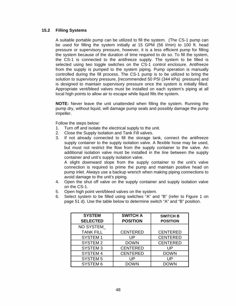
48
15.2 Filling Systems
A suitable portable pump can be utilized to fill the system. (The CS-1 pump can be used for filling the system initially at 15 GPM (56 l/min) to 100 ft. head pressure or supervisory pressure, however, it is a less efficient pump for filling the system because of the duration of time required to do so. To fill the system, the CS-1 is connected to the antifreeze supply. The system to be filled is selected using two toggle switches on the CS-1 control enclosure. Antifreeze from the supply is pumped to the system piping. Pump operation is manually controlled during the fill process. The CS-1 pump is to be utilized to bring the solution to supervisory pressure, [recommended 50 PSI (344 kPa) pressure] and is designed to maintain supervisory pressure once the system is initially filled. Appropriate vent/bleed valves must be installed on each system’s piping at all local high points to allow air to escape while liquid fills the system. NOTE: Never leave the unit unattended when filling the system. Running the pump dry, without liquid, will damage pump seals and possibly damage the pump impeller.
Follow the steps below: 1. Turn off and isolate the electrical supply to the unit. 2. Close the Supply Isolation and Tank Fill valves. 3. If not already connected to fill the storage tank, connect the antifreeze
supply container to the supply isolation valve. A flexible hose may be used, but must not restrict the flow from the supply container to the valve. An additional isolation valve must be installed in the line between the supply container and unit’s supply isolation valve.
A slight downward slope from the supply container to the unit’s valve connection is required to prime the pump and maintain positive head on pump inlet. Always use a backup wrench when making piping connections to avoid damage to the unit’s piping.
4. Open the shut off valve on the supply container and supply isolation valve on the CS-1.
5. Open high point vent/bleed valves on the system. 6. Select system to be filled using switches “A” and “B” (refer to Figure 1 on
page 51 d). Use the table below to determine switch “A” and “B” position.
SYSTEM SELECTED
SWITCH A POSITION
SWITCH B POSITION
NO SYSTEM_ TANK FILL CENTERED CENTEREDSYSTEM 1 UP CENTEREDSYSTEM 2 DOWN CENTEREDSYSTEM 3 CENTERED UPSYSTEM 4 CENTERED DOWNSYSTEM 5 UP UPSYSTEM 6 DOWN DOWN
49
7. With the CS-1’s switch in the “OFF” position turn on the power supply to the unit. Turn the “Off-On” switch to “ON”.
8. Switch the “Man-O-AUTO” switch on the unit control panel to “Man”. Liquid will begin to fill the selected system.
9. As the system fills, monitor the system vent/bleed valves. Close each valve when liquid leaks from it.
10. When the liquid leaks from the uppermost vent/bleed valve, close the vent valve. The system pressure switch will close that system’s solenoid valve. The pump pressure switch will turn the pump off.
11. If another system is to be filled, turn the “Man-O-AUTO” switch to OFF and select the next system using switches A and B.
12. Turn the “Man-O-AUTO” switch to “Man” and repeat steps 8 through 10. 13. After filling all systems and the CS-1 tank, close the supply isolation valve. 14. All air must be out of the system before switching the unit to maintenance
mode. Follow the system manufacturer’s recommendations to ensure all air is removed.
16.0 SYSTEM AND SOLUTION TEST AND MAINTENANCE
Field mixing of propylene glycol and site water is strictly prohibited, as the control of the mixture cannot be assured. Improper field mixing of solution can result in reduced capability to prevent freezing or to control a fire. Firefighter Eliminator F is already premixed and ready to use. Filling the System In the main drain line between the valve and primary check valve inlet, a tee is provided with a 1” NPT connection for supply and maintenance of the antifreeze solution to the system above the check valve. A suitable portable pump can be utilized to fill the system to the static water pressure. (The CS-1 pump can be used for filling the system initially at 15 GPM (56 l/min) to 100 ft. head pressure or system static pressure. However, it is a less efficient pump for filling the system because of the duration of time required to do so. The CS-1 pump is to be utilized to bring the solution to maintenance pressure [recommended 50 PSI (344 kPa)] and is designed to maintain supervisory pressure once the system is initially filled. When filling the system with antifreeze solution, all air must be bled from the system (as described in data page 45 a-j) in order to make final and maintained antifreeze solution pressure non-compressible. 16.1 Testing the Solution
Antifreeze solution shall be checked quarterly (for gridded systems), or semi-annually (for tree type configurations) with a refractometer to detect the concentration of antifreeze solution and effectiveness against freezing. Sampling shall be taken from multiple points within the freezer system (refer to the instructions on data pages 45 e and 45 i for fluid sampling). When draining sample antifreeze solution from the system, be sure to shut off the system control valve directly upstream of the deluge valve so that water doesn’t enter the system. After the CS-1 pump has restored the antifreeze solution pressure, ensure that the water supply control valve is returned to the fully open position once fluid sampling is completed. Multiple propylene glycol/water solution test
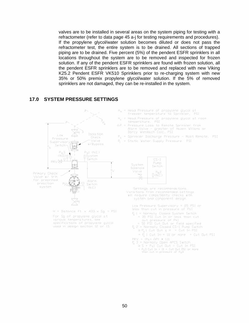
50
valves are to be installed in several areas on the system piping for testing with a refractometer (refer to data page 45 a-j for testing requirements and procedures). If the propylene glycol/water solution becomes diluted or does not pass the refractometer test, the entire system is to be drained. All sections of trapped piping are to be drained. Five percent (5%) of the pendent ESFR sprinklers in all locations throughout the system are to be removed and inspected for frozen solution. If any of the pendent ESFR sprinklers are found with frozen solution, all the pendent ESFR sprinklers are to be removed and replaced with new Viking K25.2 Pendent ESFR VK510 Sprinklers prior to re-charging system with new 35% or 50% premix propylene glycol/water solution. If the 5% of removed sprinklers are not damaged, they can be re-installed in the system.
17.0 SYSTEM PRESSURE SETTINGS
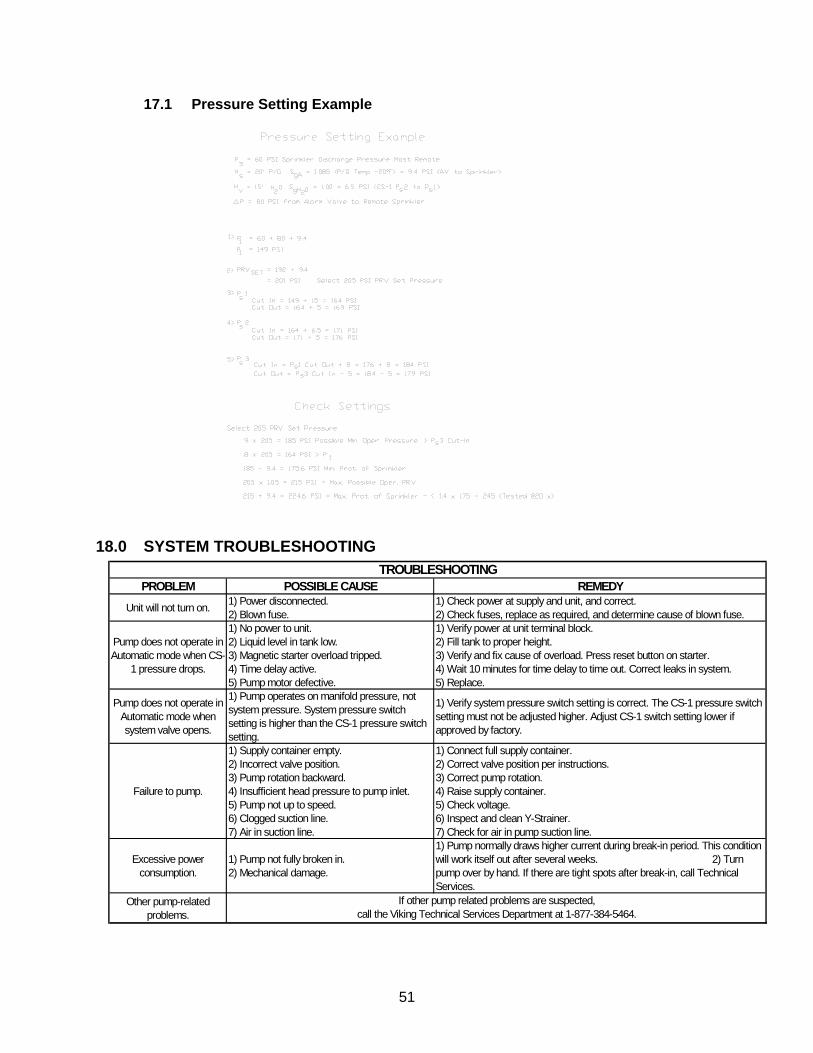
51
17.1 Pressure Setting Example
18.0 SYSTEM TROUBLESHOOTING
PROBLEM POSSIBLE CAUSE REMEDY
Unit will not turn on. 1) Power disconnected. 2) Blown fuse.
1) Check power at supply and unit, and correct. 2) Check fuses, replace as required, and determine cause of blown fuse.
Pump does not operate in Automatic mode when CS-
1 pressure drops.
1) No power to unit. 2) Liquid level in tank low. 3) Magnetic starter overload tripped. 4) Time delay active. 5) Pump motor defective.
1) Verify power at unit terminal block. 2) Fill tank to proper height. 3) Verify and fix cause of overload. Press reset button on starter. 4) Wait 10 minutes for time delay to time out. Correct leaks in system. 5) Replace.
Pump does not operate in Automatic mode when system valve opens.
1) Pump operates on manifold pressure, not system pressure. System pressure switch setting is higher than the CS-1 pressure switch setting.
1) Verify system pressure switch setting is correct. The CS-1 pressure switch setting must not be adjusted higher. Adjust CS-1 switch setting lower if approved by factory.
Failure to pump.
1) Supply container empty. 2) Incorrect valve position. 3) Pump rotation backward. 4) Insufficient head pressure to pump inlet. 5) Pump not up to speed. 6) Clogged suction line. 7) Air in suction line.
1) Connect full supply container. 2) Correct valve position per instructions. 3) Correct pump rotation. 4) Raise supply container. 5) Check voltage. 6) Inspect and clean Y-Strainer. 7) Check for air in pump suction line.
Excessive power consumption.
1) Pump not fully broken in. 2) Mechanical damage.
1) Pump normally draws higher current during break-in period. This condition will work itself out after several weeks. 2) Turn pump over by hand. If there are tight spots after break-in, call Technical Services.
Other pump-related problems.
TROUBLESHOOTING
If other pump related problems are suspected, call the Viking Technical Services Department at 1-877-384-5464.
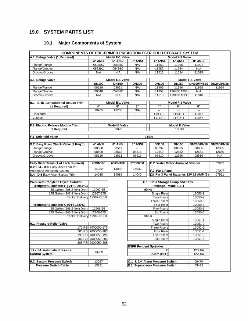
52
19.0 SYSTEM PARTS LIST 19.1 Major Components of System
A.1 Deluge Valve (1 Required)4" ANSI 6" ANSI 8" ANSI 4" ANSI 6" ANSI 8" ANSI
Flange/Flange 05909C 05906C N/A 11953 11955 11991Flange/Groove 05839C 05456C N/A 11952 11954 N/AGroove/Groove N/A N/A N/A 11513 11524 11018
A.1 Deluge ValveDN100 DN150 DN200 DN100 DN150 DN200/PN 10 DN200/PN16
Flange/Flange 08629 08631 N/A 11965 11956 11995 11999Flange/Groove 09540 05456C N/A 11958 12640/11954 N/AGroove/Groove N/A N/A N/A 11513 11910/11524 11018
B.1 - B.15 Conventional Deluge Trim (1 Required) 4" 6" 8" 4" 6" 8"
10205 10206 N/A -- -- --Horizontal -- -- -- 11938-1 11939-1 11072Vertical -- -- -- 11712-1 11714-1 11077
F.1 Electric Release Module Trim1 Required
F.1 Solenoid Valve
D.2 Easy Riser Check Valve (2 Req'd) 4" ANSI 6" ANSI 8" ANSI DN100 DN150 DN200/PN10 DN200/PN16Flange/Flange 08508 08511 -- 08797 08335 08836 12355Flange/Groove 08509 08512 08515 12649 12652 12651 12650Groove/Groove 08510 08513 08516 08510 12356 08516 N/A
Easy Riser Trims (1 of each required) 4"/DN100 6"/DN150 8"/DN200 07862H.2, H.4 - H.8 Easy Riser Trim for Preprimed Preaction System 14032 14032 14032 07907D.4 - D.5 Easy Riser Bypass Trim 14038 14039 14040 07921
Premixed Propylene Glycol SolutionFirefighter Eliminator F (-21°F/-29.4°C)
55 Gallon (208.2 liter) Drum 12967-55275 Gallon (946.3 liter) Drum 12967-275 13050-1
Tanker Delivery 12967-BULK 13050-213050-3
Firefighter Eliminator C (6°F/-14.5°C) 13050-455 Gallon (208.2 liter) Drum 12968-55 13050-5
275 Gallon (946.3 liter) Drum 12968-275 13050-6Tanker Delivery 12968-BULK
13051-1H.1 Pressure Relief Valve 13051-2
175 PSI 7000050-175 13051-3185 PSI 7000050-185 13051-4195 PSI 7000050-195 13051-5200 PSI 7000050-200 13051-6205 PSI 7000050-205
J.1 - J.4 Automatic Pressure 12080AControl System 12200A
H.3 System Pressure Switch 13057 C.1 & J.4 Alarm Pressure Switch 09470 Pressure Switch Cable 13231 09472
Five Risers
Six Risers
COMPONENTS OF PRE-PRIMED PREACTION ESFR COLD STORAGE SYSTEM
13289
C.2 Water Motor Alarm w/ Strainer
F.2 Par 3 Panel(2) Par 3 Panel Batteries 12V 12 AMP (2 r
ESFR Pendent Sprinkler1"
25mm (BSP)
Four Riser
Package - Model CS-1
Six Risers
50 HzSingle Riser
Single RiserTwo Risers
Two RisersThree Risers
Four RiserFive Risers
Model E-1 Valve Model F-1 Valve
Model E-1 Valve Model F-1 Valve
Model F-1 Valve
E.1 Supervisory Pressure Switch
Model E-1 Valve
Model F Valve09070 10830
Three Risers
G.1 Cold Storage Pump and Tank
Model E Valve
11601
60 Hz
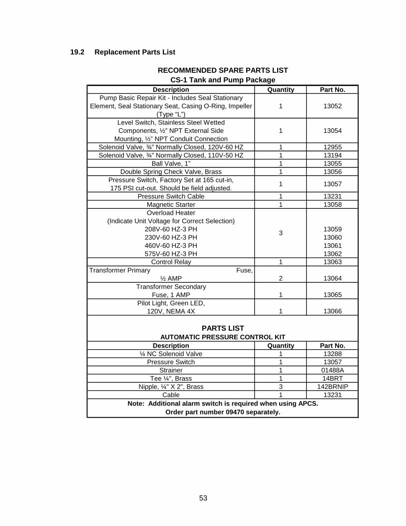
53
19.2 Replacement Parts List
Description Quantity Part No.Pump Basic Repair Kit - Includes Seal Stationary
Element, Seal Stationary Seat, Casing O-Ring, Impeller (Type “L”)
1 13052
Level Switch, Stainless Steel Wetted Components, ½” NPT External Side
Mounting, ½” NPT Conduit Connection1 13054
Solenoid Valve, ¾” Normally Closed, 120V-60 HZ 1 12955Solenoid Valve, ¾” Normally Closed, 110V-50 HZ 1 13194
Ball Valve, 1” 1 13055Double Spring Check Valve, Brass 1 13056
Pressure Switch, Factory Set at 165 cut-in, 175 PSI cut-out. Should be field adjusted. 1 13057
Pressure Switch Cable 1 13231Magnetic Starter 1 13058Overload Heater
(Indicate Unit Voltage for Correct Selection) 208V-60 HZ-3 PH 13059230V-60 HZ-3 PH 13060460V-60 HZ-3 PH 13061575V-60 HZ-3 PH 13062
Control Relay 1 13063Transformer Primary Fuse,
½ AMP 2 13064Transformer Secondary
Fuse, 1 AMP 1 13065Pilot Light, Green LED,
120V, NEMA 4X 1 13066
Description Quantity Part No.¼ NC Solenoid Valve 1 13288
Pressure Switch 1 13057Strainer 1 01488A
Tee ¼", Brass 1 14BRTNipple, ¼" X 2", Brass 3 142BRNIP
Cable 1 13231
RECOMMENDED SPARE PARTS LIST
3
PARTS LIST
Note: Additional alarm switch is required when using APCS. Order part number 09470 separately.
CS-1 Tank and Pump Package
AUTOMATIC PRESSURE CONTROL KIT


