ETC TECHNOLOGICAL PLATFORM / URENCO & AREVA STATE & DEVELOPMENT FORECAST
IBRTM
1
IBRTM
ENRICHMENT TECHNOLOGY COMPANY
TECHNOLOGICAL PLATFORM.
URENCO & AREVA STATE & DEVELOPMENT
FORECAST
VOLUME I
DESIGN & TECHNOECONOMIC PERFORMANCE ATTRIBUTES
OF THE SIX GENERATIONS OF URENCO/ETC GC &
AUXILIARY EQUIPMENT
INTERNATIONAL BUSINESS RELATIONS LLC
Moscow, 2013
ETC TECHNOLOGICAL PLATFORM / URENCO & AREVA STATE & DEVELOPMENT FORECAST
IBRTM
4
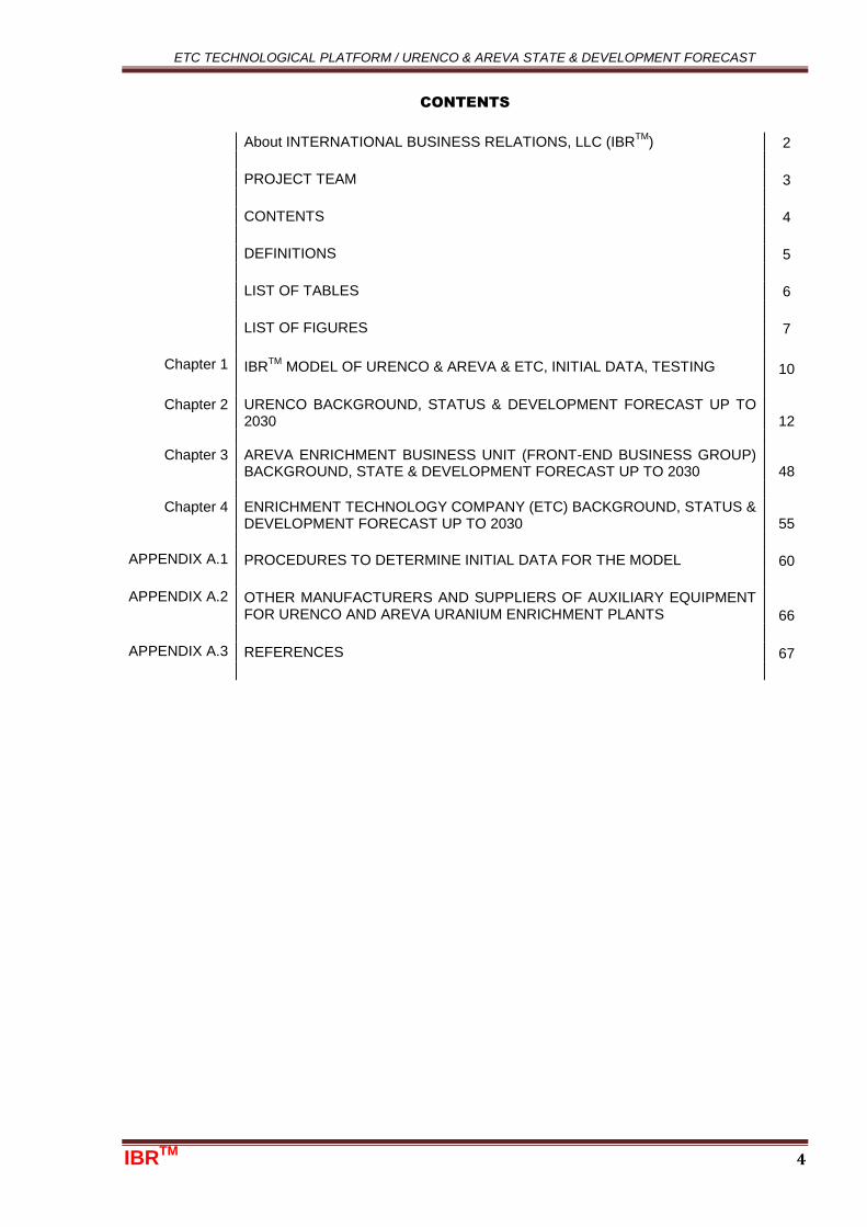
CONTENTS
About INTERNATIONAL BUSINESS RELATIONS, LLC (IBRTM
) 2
PROJECT TEAM 3
CONTENTS 4
DEFINITIONS 5
LIST OF TABLES 6
LIST OF FIGURES 8
Chapter 1
ANALYSIS OF GEOMETRICAL DIMENSIONS & CAPACITY OF THE SIX GENERATIONS OF GC MANUFACTURED BY URENCO/ETC COMPANIES 10
Chapter 2 ANALYSIS OF URENCO/ETC GC DESIGN 19
Chapter 3
ANALYSIS OF POWER CONSUMPTION BY THE G3, TC-11, TC-12 & TC-21 GC MODELS 19
Chapter 4 GC RELIABILITY 20
Chapter 5 ANALYSIS OF MODELS TC-12 & TC-21 GC PRICE EVOLUTION 20
APPENDIX A.1
IDENTIFICATION OF AREA BOUNDARIES ENCOMPASSING THE GEOMETRICAL DIMENSIONS OF MODELS TC-12 AND TC-21 GC 21
APPENDIX A.2
IDENTIFICATION OF THE GC NUMBER IN A SINGLE CASCADE WITHIN URENCO SELECTED PLANT PROJECTS 33
APPENDIX A.3 DESIGN ANALYSIS OF URENCO/ETC GC 42
APPENDIX A.4 CARBON FIBER FOR ETC MANUFACTURED GC 54
ETC TECHNOLOGICAL PLATFORM / URENCO & AREVA STATE & DEVELOPMENT FORECAST
IBRTM
5
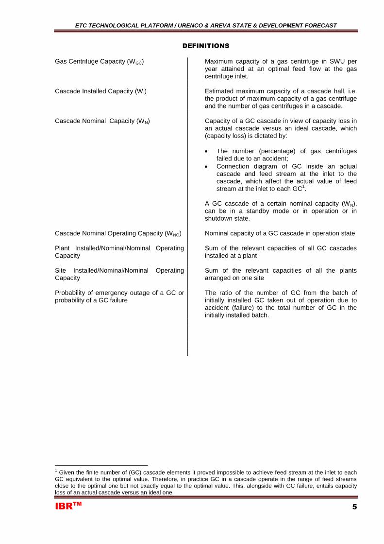
DEFINITIONS
Gas Centrifuge Capacity (WGC) Maximum capacity of a gas centrifuge in SWU per
year attained at an optimal feed flow at the gas centrifuge inlet.
Cascade Installed Capacity (W I) Estimated maximum capacity of a cascade hall, i.e.
the product of maximum capacity of a gas centrifuge and the number of gas centrifuges in a cascade.
Cascade Nominal Capacity (WN) Capacity of a GC cascade in view of capacity loss in
an actual cascade versus an ideal cascade, which (capacity loss) is dictated by:
The number (percentage) of gas centrifuges failed due to an accident;
Connection diagram of GC inside an actual cascade and feed stream at the inlet to the cascade, which affect the actual value of feed stream at the inlet to each GC
1.
A GC cascade of a certain nominal capacity (WN), can be in a standby mode or in operation or in shutdown state.
Cascade Nominal Operating Capacity (WNO) Nominal capacity of a GC cascade in operation state
Plant Installed/Nominal/Nominal Operating Capacity
Sum of the relevant capacities of all GC cascades installed at a plant
Site Installed/Nominal/Nominal Operating Capacity
Sum of the relevant capacities of all the plants arranged on one site
Probability of emergency outage of a GC or probability of a GC failure
The ratio of the number of GC from the batch of initially installed GC taken out of operation due to accident (failure) to the total number of GC in the initially installed batch.
1 Given the finite number of (GC) cascade elements it proved impossible to achieve feed stream at the inlet to each
GC equivalent to the optimal value. Therefore, in practice GC in a cascade operate in the range of feed streams close to the optimal one but not exactly equal to the optimal value. This, alongside with GC failure, entails capacity loss of an actual cascade versus an ideal one.
ETC TECHNOLOGICAL PLATFORM / URENCO & AREVA STATE & DEVELOPMENT FORECAST
IBRTM
6
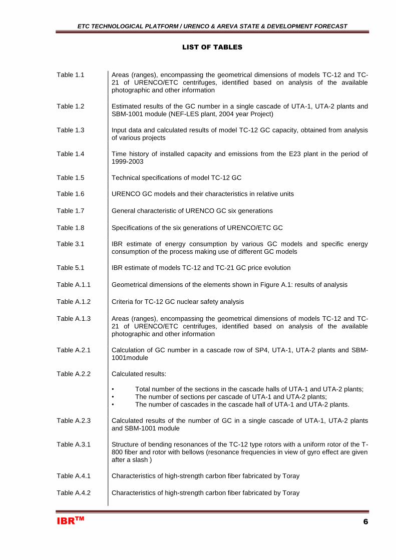
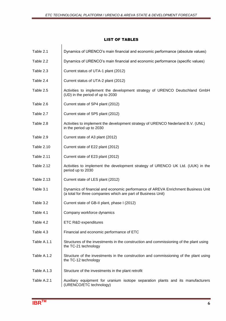
LIST OF TABLES
Table 1.1 Areas (ranges), encompassing the geometrical dimensions of models TC-12 and TC-21 of URENCO/ETC centrifuges, identified based on analysis of the available photographic and other information
Table 1.2 Estimated results of the GC number in a single cascade of UTA-1, UTA-2 plants and SBM-1001 module (NEF-LES plant, 2004 year Project)
Table 1.3 Input data and calculated results of model TC-12 GC capacity, obtained from analysis of various projects
Table 1.4 Time history of installed capacity and emissions from the E23 plant in the period of 1999-2003
Table 1.5 Technical specifications of model TC-12 GC
Table 1.6 URENCO GC models and their characteristics in relative units
Table 1.7 General characteristic of URENCO GC six generations
Table 1.8 Specifications of the six generations of URENCO/ETC GC
Table 3.1 IBR estimate of energy consumption by various GC models and specific energy consumption of the process making use of different GC models
Table 5.1 IBR estimate of models TC-12 and TC-21 GC price evolution
Table A.1.1 Geometrical dimensions of the elements shown in Figure A.1: results of analysis
Table A.1.2 Criteria for TC-12 GC nuclear safety analysis
Table A.1.3 Areas (ranges), encompassing the geometrical dimensions of models TC-12 and TC-21 of URENCO/ETC centrifuges, identified based on analysis of the available photographic and other information
Table A.2.1 Calculation of GC number in a cascade row of SP4, UTA-1, UTA-2 plants and SBM-1001module
Table A.2.2 Calculated results: • Total number of the sections in the cascade halls of UTA-1 and UTA-2 plants; • The number of sections per cascade of UTA-1 and UTA-2 plants; • The number of cascades in the cascade hall of UTA-1 and UTA-2 plants.
Table A.2.3 Calculated results of the number of GC in a single cascade of UTA-1, UTA-2 plants and SBM-1001 module
Table A.3.1 Structure of bending resonances of the TC-12 type rotors with a uniform rotor of the T-800 fiber and rotor with bellows (resonance frequencies in view of gyro effect are given after a slash )
Table A.4.1 Characteristics of high-strength carbon fiber fabricated by Toray
Table A.4.2 Characteristics of high-strength carbon fiber fabricated by Toray
ETC TECHNOLOGICAL PLATFORM / URENCO & AREVA STATE & DEVELOPMENT FORECAST
IBRTM
7
Table A.4.3 Most probable makes of carbon fibers used in the structure of GC manufactured by ETC and formula of their laying
ETC TECHNOLOGICAL PLATFORM / URENCO & AREVA STATE & DEVELOPMENT FORECAST
IBRTM
8
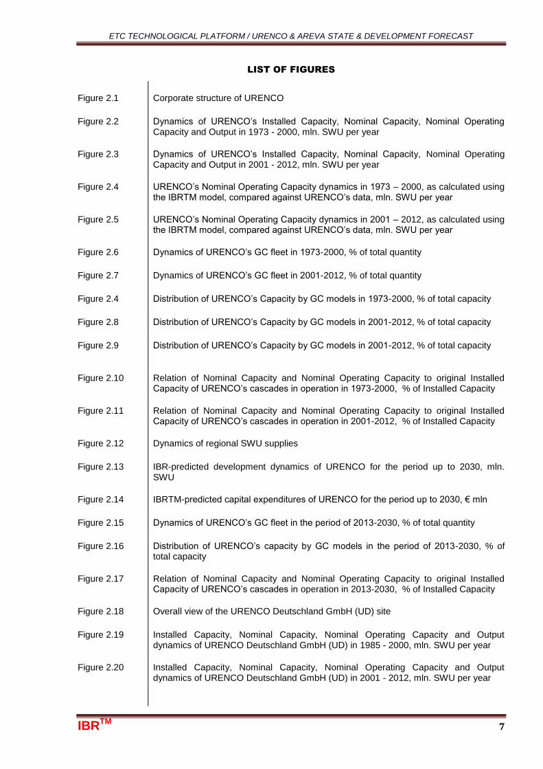
LIST OF FIGURES
Figure 1.1 Model TC-12 GC failure probability for GC capacity equal to 39.4 (diagram 1), 39.7 (diagram 2), 39.9 (diagram 3) and 40.3 (diagram 4) SWU per year, %
Figure 1.2 Relative linear velocity of the rotor revolution and rotor relative length, as a function of URENCO centrifuge generation [6]
Figure 3.1 Evolution of specific energy consumption on URENCO Deutschland GmbH site, kW x hour / SWU
Figure A.1.1 Figure from URENCO Annual Report 2005, page 18
Figure A.1.2 Centrifuges manufactured by ETC
Figure A.1.3 TC-12 gas centrifuges manufactured by ETC
Figure A.1.4 TC-12 gas centrifuges manufactured by ETC
Figure A.1.5 TC-12 gas centrifuges manufactured by ETC
Figure A.1.6 Passage between TC-12 centrifuge sections
Figure A.1.7 Passage between TC-12 centrifuge sections
Figure A.1.8 Start of winding in the video clip, the carriage (marked out by red) moves to the right
Figure A.1.9 The carriage has turned round and is moving to the left
Figure A.1.10 The pattern of forming the strengthening winding on the end of composite tube (Patent EP0406596B1)
Figure A.1.11 Video fragments
Figure A.2.1 Separation Building Module, first floor (The National Enrichment Facility Project, 2004)
Figure A.2.2 The SP4 plant cascade hall
Figure A.2.3 The UTA-1 plant cascade hall
Figure A.2.4 General view of UTA-1 plant and standard module layout
Figure A.2.5 General view of UTA-2 plant and standard module layout
Figure A.2.6 Fragment of Process Service Area at SBM plant of National Enrichment Facility (2004 year Project)
Figure A.3.1 Structural element as a fiber-reinforced cylindrical tube: US Patent 5134003, dated 28.07.1992, Uranit Co. (German Patent DE4100816 dated 14.01.1991)
Figure A.3.2 Two methods of bellows fastening for joining two composite tubes
Figure A.3.3 Possible technology of mounting a steel bellows on a composite tube
Figure A.3.4 Machining of an end element blank
ETC TECHNOLOGICAL PLATFORM / URENCO & AREVA STATE & DEVELOPMENT FORECAST
IBRTM
9
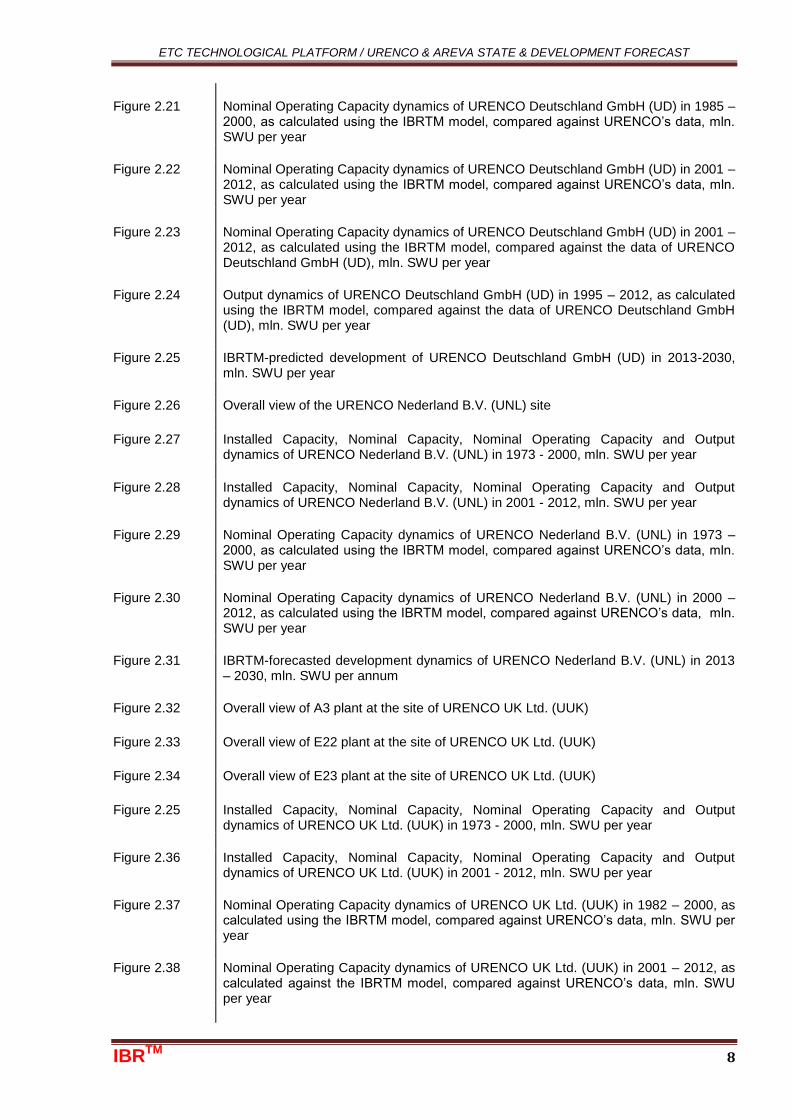
Figure A.3.5 Technology of metal flange parts mounting on a composite tube
Figure A.3.6 Manufacturing technology and design of (rotor) drive plate of an ultracentrifuge, inertial accumulator or other similar device
Figure A.3.7 The motor working parameters, effective power and efficiency depending on voltage
Figure A.3.8 Example of magnetization lines pattern
Figure A.3.9 TC-12 GC upper section
Figure A.3.10 A drawing to Patent DE2123654 dated 13.05.1971
Figure A.3.11 Centrifuge lower dampers (supports)
ETC TECHNOLOGICAL PLATFORM / URENCO & AREVA STATE & DEVELOPMENT FORECAST
IBRTM 1
IBRTM
TECHNOLOGY PLATFORM OF
ENRICHMENT TECHNOLOGY COMPANY.
STATUS AND DEVELOMENT PROSPECTS OF
URENCO & AREVA & ETC
VOLUME II
STATUS AND DEVELOPMENT PROSPECTS OF
URENCO & AREVA & ETC
INTERNATIONAL BUSINESS RELATIONS LLC
Moscow, 2013
ETC TECHNOLOGICAL PLATFORM / URENCO & AREVA STATE & DEVELOPMENT FORECAST
IBRTM 4
CONTENTS
About INTERNATIONAL BUSINESS RELATIONS, LLC (IBRTM
) 2
PROJECT TEAM 3
CONTENTS 4
DEFINITIONS 5
LIST OF TABLES 6
LIST OF FIGURES 7
Chapter 1 IBR
TM MODEL OF URENCO & AREVA & ETC, INITIAL DATA, TESTING 10
Chapter 2 URENCO BACKGROUND, STATUS & DEVELOPMENT FORECAST UP TO
2030 12
Chapter 3
AREVA ENRICHMENT BUSINESS UNIT (FRONT-END BUSINESS GROUP) BACKGROUND, STATE & DEVELOPMENT FORECAST UP TO 2030 48
Chapter 4 ENRICHMENT TECHNOLOGY COMPANY (ETC) BACKGROUND, STATUS &
DEVELOPMENT FORECAST UP TO 2030 55
APPENDIX A.1 PROCEDURES TO DETERMINE INITIAL DATA FOR THE MODEL 60
APPENDIX A.2
OTHER MANUFACTURERS AND SUPPLIERS OF AUXILIARY EQUIPMENT FOR URENCO AND AREVA URANIUM ENRICHMENT PLANTS 66
APPENDIX A.3 REFERENCES 67
ETC TECHNOLOGICAL PLATFORM / URENCO & AREVA STATE & DEVELOPMENT FORECAST
IBRTM 6
LIST OF TABLES
Table 2.1 Dynamics of URENCO’s main financial and economic performance (absolute values)
Table 2.2 Dynamics of URENCO’s main financial and economic performance (specific values)
Table 2.3 Current status of UTA-1 plant (2012)
Table 2.4 Current status of UTA-2 plant (2012)
Table 2.5 Activities to implement the development strategy of URENCO Deutschland GmbH (UD) in the period of up to 2030
Table 2.6 Current state of SP4 plant (2012)
Table 2.7 Current state of SP5 plant (2012)
Table 2.8 Activities to implement the development strategy of URENCO Nederland B.V. (UNL) in the period up to 2030
Table 2.9 Current state of A3 plant (2012)
Table 2.10 Current state of E22 plant (2012)
Table 2.11 Current state of E23 plant (2012)
Table 2.12 Activities to implement the development strategy of URENCO UK Ltd. (UUK) in the period up to 2030
Table 2.13 Current state of LES plant (2012)
Table 3.1 Dynamics of financial and economic performance of AREVA Enrichment Business Unit (a total for three companies which are part of Business Unit)
Table 3.2 Current state of GB-II plant, phase I (2012)
Table 4.1 Company workforce dynamics
Table 4.2 ETC R&D expenditures
Table 4.3 Financial and economic performance of ETC
Table A.1.1 Structures of the investments in the construction and commissioning of the plant using the TC-21 technology
Table A.1.2 Structure of the investments in the construction and commissioning of the plant using the TC-12 technology
Table A.1.3 Structure of the investments in the plant retrofit
Table A.2.1 Auxiliary equipment for uranium isotope separation plants and its manufacturers (URENCO/ETC technology)
ETC TECHNOLOGICAL PLATFORM / URENCO & AREVA STATE & DEVELOPMENT FORECAST
IBRTM 7
LIST OF FIGURES
Figure 2.1 Corporate structure of URENCO
Figure 2.2 Dynamics of URENCO’s Installed Capacity, Nominal Capacity, Nominal Operating Capacity and Output in 1973 - 2000, mln. SWU per year
Figure 2.3 Dynamics of URENCO’s Installed Capacity, Nominal Capacity, Nominal Operating Capacity and Output in 2001 - 2012, mln. SWU per year
Figure 2.4 URENCO’s Nominal Operating Capacity dynamics in 1973 – 2000, as calculated using the IBRTM model, compared against URENCO’s data, mln. SWU per year
Figure 2.5 URENCO’s Nominal Operating Capacity dynamics in 2001 – 2012, as calculated using the IBRTM model, compared against URENCO’s data, mln. SWU per year
Figure 2.6 Dynamics of URENCO’s GC fleet in 1973-2000, % of total quantity
Figure 2.7 Dynamics of URENCO’s GC fleet in 2001-2012, % of total quantity
Figure 2.4 Distribution of URENCO’s Capacity by GC models in 1973-2000, % of total capacity
Figure 2.8 Distribution of URENCO’s Capacity by GC models in 2001-2012, % of total capacity
Figure 2.9 Distribution of URENCO’s Capacity by GC models in 2001-2012, % of total capacity
Figure 2.10 Relation of Nominal Capacity and Nominal Operating Capacity to original Installed Capacity of URENCO’s cascades in operation in 1973-2000, % of Installed Capacity
Figure 2.11 Relation of Nominal Capacity and Nominal Operating Capacity to original Installed Capacity of URENCO’s cascades in operation in 2001-2012, % of Installed Capacity
Figure 2.12 Dynamics of regional SWU supplies
Figure 2.13 IBR-predicted development dynamics of URENCO for the period up to 2030, mln. SWU
Figure 2.14 IBRTM-predicted capital expenditures of URENCO for the period up to 2030, € mln
Figure 2.15 Dynamics of URENCO’s GC fleet in the period of 2013-2030, % of total quantity
Figure 2.16 Distribution of URENCO’s capacity by GC models in the period of 2013-2030, % of total capacity
Figure 2.17 Relation of Nominal Capacity and Nominal Operating Capacity to original Installed Capacity of URENCO’s cascades in operation in 2013-2030, % of Installed Capacity
Figure 2.18 Overall view of the URENCO Deutschland GmbH (UD) site
Figure 2.19 Installed Capacity, Nominal Capacity, Nominal Operating Capacity and Output dynamics of URENCO Deutschland GmbH (UD) in 1985 - 2000, mln. SWU per year
Figure 2.20 Installed Capacity, Nominal Capacity, Nominal Operating Capacity and Output dynamics of URENCO Deutschland GmbH (UD) in 2001 - 2012, mln. SWU per year
ETC TECHNOLOGICAL PLATFORM / URENCO & AREVA STATE & DEVELOPMENT FORECAST
IBRTM 8
Figure 2.21
Nominal Operating Capacity dynamics of URENCO Deutschland GmbH (UD) in 1985 – 2000, as calculated using the IBRTM model, compared against URENCO’s data, mln. SWU per year
Figure 2.22 Nominal Operating Capacity dynamics of URENCO Deutschland GmbH (UD) in 2001 – 2012, as calculated using the IBRTM model, compared against URENCO’s data, mln. SWU per year
Figure 2.23 Nominal Operating Capacity dynamics of URENCO Deutschland GmbH (UD) in 2001 – 2012, as calculated using the IBRTM model, compared against the data of URENCO Deutschland GmbH (UD), mln. SWU per year
Figure 2.24 Output dynamics of URENCO Deutschland GmbH (UD) in 1995 – 2012, as calculated using the IBRTM model, compared against the data of URENCO Deutschland GmbH (UD), mln. SWU per year
Figure 2.25 IBRTM-predicted development of URENCO Deutschland GmbH (UD) in 2013-2030, mln. SWU per year
Figure 2.26 Overall view of the URENCO Nederland B.V. (UNL) site
Figure 2.27 Installed Capacity, Nominal Capacity, Nominal Operating Capacity and Output dynamics of URENCO Nederland B.V. (UNL) in 1973 - 2000, mln. SWU per year
Figure 2.28 Installed Capacity, Nominal Capacity, Nominal Operating Capacity and Output dynamics of URENCO Nederland B.V. (UNL) in 2001 - 2012, mln. SWU per year
Figure 2.29 Nominal Operating Capacity dynamics of URENCO Nederland B.V. (UNL) in 1973 – 2000, as calculated using the IBRTM model, compared against URENCO’s data, mln. SWU per year
Figure 2.30 Nominal Operating Capacity dynamics of URENCO Nederland B.V. (UNL) in 2000 – 2012, as calculated using the IBRTM model, compared against URENCO’s data, mln. SWU per year
Figure 2.31 IBRTM-forecasted development dynamics of URENCO Nederland B.V. (UNL) in 2013 – 2030, mln. SWU per annum
Figure 2.32 Overall view of A3 plant at the site of URENCO UK Ltd. (UUK)
Figure 2.33 Overall view of E22 plant at the site of URENCO UK Ltd. (UUK)
Figure 2.34 Overall view of E23 plant at the site of URENCO UK Ltd. (UUK)
Figure 2.25 Installed Capacity, Nominal Capacity, Nominal Operating Capacity and Output dynamics of URENCO UK Ltd. (UUK) in 1973 - 2000, mln. SWU per year
Figure 2.36 Installed Capacity, Nominal Capacity, Nominal Operating Capacity and Output dynamics of URENCO UK Ltd. (UUK) in 2001 - 2012, mln. SWU per year
Figure 2.37 Nominal Operating Capacity dynamics of URENCO UK Ltd. (UUK) in 1982 – 2000, as calculated using the IBRTM model, compared against URENCO’s data, mln. SWU per year
Figure 2.38 Nominal Operating Capacity dynamics of URENCO UK Ltd. (UUK) in 2001 – 2012, as calculated against the IBRTM model, compared against URENCO’s data, mln. SWU per year
ETC TECHNOLOGICAL PLATFORM / URENCO & AREVA STATE & DEVELOPMENT FORECAST
IBRTM 9
Figure 2.39 IBRTM
-forecasted dynamics of URENCO UK Ltd. (UUK) in 2013 – 2030, mln. SWU per year
Figure 2.40 Overall view of URENCO USA Facility’s plant site (2012)
Figure 2.41 Installed Capacity, Nominal Capacity, Nominal Operating Capacity and Output dynamics of URENCO USA Inc. (UUS) in 2010 - 2012, mln. SWU per annum
Figure 2.42 IBRTM
-forecasted development dynamics of URENCO USA Inc. (UUS) in 2013 – 2030, mln. SWU per year
Figure 3.1 George Besse II South Unit
Figure 3.2 George Besse II North Unit
Figure 3.3 Installed Capacity, Nominal Capacity, Nominal Operating Capacity and Output dynamics of AREVA Enrichment Business Unit in 2009 - 2012, mln. SWU per year
Figure 3.4 Nominal Operating Capacity dynamics of AREVA Enrichment Business Unit for 2009 – 2012, as calculated using the IBRTM model, compared against AREVA’s data, mln. SWU per year
Figure 3.5 IBR-predicted development dynamics of AREVA Enrichment Business Unit for the period until 2030, mln. SWU
Figure 3.6 IBR-predicted capital expenditures of Enrichment Business Unit for the period until 2030, € mln.
Figure 3.7 Relation of the Nominal Capacity and the Nominal Operating Capacity to the original Installed Capacity the AREVA Enrichment Business Unit cascades in operation in 1913-2030, % от Installed Capacity
Figure 4.1 Output of TC-12 and TC-21 GCs by URENCO/ETC in 1991-2012, number of GCs per annum
Figure 4.2 Output of TC-12 and TC-21 GCs by URENCO/ETC in 1991-2012, SWU per year
Figure 4.3 Dynamics of the ECT product (GC) output and supply compared, number of GCs in the equivalent of the TC-12 GCs
Figure 4.4 Dynamics of the ETC product (GC) output and supply compared, SWU
Figure 4.5 Output of TC-12 and TC-21 GCs by ETC in 2013-2030, number of GCs per annum
Figure 4.6 Output of TC-12 and TC-21 GCs by ETC in 2013-2030, SWU per year
Figure A.1.1 Product manufacturing and nominal capacity dynamics of URENCO Deutschland GmbH


