
1
Evaluation of geometrical effects of microneedles on
skin penetration by CT scan and finite element
analysis
Eriketi Z. Loizidou*a,b, Nicholas T. Inouec, Johnny Ashton-Barnetta, David A. Barrow*c, Chris J.
Allender*a
aSchool of Pharmacy, Cardiff University, CF10 3NB, United Kingdom
bSchool of Science and Technology, Middlesex University, NW4 4BT, United Kingdom
cSchool of Engineering, Cardiff University, CF24 3AA, United Kingdom
Corresponding Authors
*Eriketi Z. Loizidou, Middlesex University, School of Science and Technology, Department of
Natural Sciences, The Burroughs, NW4 4BT, London, UK. Email: [email protected]
* Chris J. Allender, Cardiff University, School of Pharmacy and Pharmaceutical Sciences, King
Edward VII Avenue, CF10 3NB, Cardiff, UK. Email: [email protected]
* David A. Barrow, Cardiff University, School of Engineering, 14-17 The Parade, CF24 1AA,
Cardiff, UK. Email: [email protected]

2
Abstract
Computerized tomography (CT scan) imaging and finite element analysis were employed to
investigate how the geometric composition of microneedles affects their mechanical strength and
penetration characteristics. Simulations of microneedle arrays, comprising triangular, square and
hexagonal microneedle base, revealed a linear dependence of the mechanical strength to the
number of vertices in the polygon base. A laser-enabled, micromoulding technique was then
used to fabricate 3x3 microneedle arrays, each individual microneedle having triangular, square
or hexagonal base geometries. Their penetration characteristics into ex-vivo porcine skin, were
investigated for the first time by CT scan imaging. This revealed greater penetration depths for
the triangular and square-based microneedles, demonstrating CT scan as a powerful and reliable
technique for studying microneedle skin penetration.
Keywords
Microneedles, microfabrication, laser ablation, computerized tomography, skin penetration,
structural mechanics simulations, COMSOL

3
1. Introduction
Microneedles are minimally invasive devices that facilitate transdermal drug delivery by creating
micron size pores through the skin1–4. Due to its viscoelastic nature5, skin is easily deformed
when microneedles are applied to its surface, and therefore, the microneedle design and
constructional material will determine the extent of skin penetration by the microneedles, and in
the resulting effect on drug permeability2. The most critical factors for microneedle skin
penetration were attributed to needle length and density6,7, tip and base diameter8–10 and
microneedle material11–13. In addition, the use of an injection applicator was found to greatly
enhance penetration with a critical role on force and velocity of microneedle injection14–16.
Studies have shown that the penetration depth is linearly correlated with microneedle length and
inversely correlated with microneedle density. The bed-of-nails effect begins to have a negative
effect on penetration, at interspacing values smaller than 150 μm14,15,17. Furthermore,
microneedles made from material of high Young’s modulus, showed enhanced mechanical
properties and penetration characteristics12,13.
In order to accurately evaluate skin permeability by microneedles of different geometries, it is
important to use highly accurate and reproducible techniques. Traditionally, histological
sectioning has been employed to determine the depth of penetration. This involves freezing and
sectioning skin that has been treated with microneedles18,19. In addition to being a cumbersome
technique, histological processing carries the risks of errors occurring. This can be during the
selection of the sampling area, and also, of possible alterations in the structure of the skin after
the microneedles are removed, as expected for hyperelastic materials such as the skin20,21. To
limit the problems associated with histological processing, whole tissue techniques such as
confocal microscopy12,22,23 and optical coherence tomography (OCT)15,24,25, are often
4
implemented. Both techniques offer the advantage of in vivo application, with OCT having the
added benefit of achieving higher penetration depths of approximately 2.0 mm, compared with
0.25 mm of confocal microscopy15.
In this study we introduce CT scanning as an alternative, non-destructive powerful technique for
studying, in detail, microneedle skin penetration through 3D visualization. CT scanning produces
3D volumetric data that are combined from a series of X-ray images taken at different rotation
angles. This renders it a popular imaging technique for use in medicine, archaeology, geology
and material sciences26. In this work, we demonstrate the application of CT scanning for drug
delivery research, by studying the skin penetration characteristics of triangular, square and
hexagonal based microneedles. Microneedle arrays, of 3x3 individual microneedles, were
prepared using a highly controlled and versatile, laser-enabled, micromoulding technique and
structural mechanics simulations were employed to assess their mechanical properties by
determining the average von Mises stresses and critical buckling loads.
2. Methods
2.1 Simulations: Simulations were performed using the Structural Mechanics Module of
COMSOL Multiphysics version 4.2b (www.comsol.com). Simulations were performed on single
microneedles with the following dimensions: footprint diameter (200 μm), height (800 μm), tip
diameter (10 μm). Regular polygons (triangle, square, hexagon, heptagon) were used as 2D base
shapes using a polygon vertex calculator (http://www.mathopenref.com/coordpolycalc.html) to
obtain the Cartesian graphic coordinates of each polygonal vertex. The Re (radius of circle
encompassing base) remained at 100 μm and this data was manually entered into COMSOL
Multiphysics software using the polygonal tool to create a 2 dimensional base shape for each of

5
the microneedles. These shapes were then linearly extruded 800 μm in the Z axis with scale
factors in the X and Y directions of 0.05, yielding a tip diameter of 10 μm and a fixed tip angle.
The triangular, square and hexagonal microneedles, as modeled in the single needle, were each
formed into 3x3 microneedle arrays with 600 μm needle-to-needle spacing, using the Array
function in COMSOL Multiphysics. A square backing plate (3 mm x 3 mm x 0.5 mm) was
joined to the bases of all 9 microneedles, for each of the three arrays. A linear elastic model
using the Young’s modulus (3.5 GPa) and density (1.24 g/cm3) values of PLGA (provided by
PURAC Biomaterials) was adopted for the microneedles. The estimated value for poisson’s ratio
was 0.3. The skin was simulated as two cylindrical structures, the top cylinder emulating the
stratum corneum and viable epidermis using 1 MPa as the Young’s modulus27 value and having
dimensions of 600 μm in diameter, 100 μm in height and the bottom cylinder emulating the
dermis using 0.066 MPa28 as the Young’s modulus value and 600 μm in diameter, 1000 μm in
height. Both epidermis and dermis were treated as nearly incompressible materials and the
Poisson’s ratio was set at 0.495. The Structural Mechanics module of COMSOL Multiphysics
was used to perform stationary and linear buckling analyses with a 5N applied force details of
which, are described in previous work29.
2.2 Microneedle array fabrication: The 3x3 inverse microneedle moulds were prepared on a
sheet of polydimethylsiloxane (PDMS) by laser ablation, using an Exitech Model 2000EF,
Microablator. This incorporates a Thales femtosecond laser source operating at 795 nm, with a 5
KHz repetition, and a pulse width of 125 fs. This light was focused at the work piece, producing
a spot of approximately 1.5 μm. All ablation patterns were designed using the software Alpha
CAM V5. 3x3 arrays of regular polygons (triangles, square, hexagons) were designed with outer
circle diameter of 200 μm, center-to-center spacing of 600 μm and distance between cuts of 25

6
μm. The laser power was 0.5 W at the workpiece. The PDMS moulds were thoroughly cleaned
by washing with ethanol and sonicating in water for 1h and subsequently, used to prepare
microneedles made of PLGA (DL-lactide / glycolide copolymer, PURAC Biomaterials) using a
high temperature, vacuum deposition method. A typical procedure involves depositing solid
PLGA on top of the micromould and then placing this in a vacuum oven at 160 oC for 60 min to
melt the PLGA granules. The vacuum was then applied for a further 30 min before being slowly
released so as to force the molten polymer into the micromould. Subsequently, the moulds were
removed from the oven and allowed to cool for 10 min at room temperature to solidify the
PLGA. These were then cooled for a further 10 min at -20 oC. The solid PLGA microneedles
were then carefully removed from the mould. All PLGA microneedles were sputter coated with
100 nm of gold using a Baltec Sputter coater, prior to imaging with the CT scanner.
2.3 CT scan imaging: Three-dimensional images of both stand-alone microneedles and
microneedle arrays inserted into porcine skin, were obtained using a Bruker microCT
SkyScan1174. This comprised an RTW 50/800 X-ray source, with an adjustable anode voltage
between 20-50 kV, and a current of up to 800 μA. Specimens were mounted on polystyrene
disks, 12 mm in diameter, using double-sided adhesive carbon disks and fitted on the CT
scanner’s specimen table. In all instances, flat field references were acquired prior to scanning,
and random movement selected to compensate for ring artifacts. The source voltage and current
were set to 50 kV and 800 μA, respectively and scans were collected at 360 degrees. Exposure
time and rotation steps were set to 60 ms and 0.050 degrees, for stand-alone microneedles, and
800 ms and 0.100 degrees for microneedles in skin. Standard mode reconstruction was
performed using NRecon, version: 1.6.9.4 and further image processing using CTVox and
Bruker’s DataViewer software.

7
3. Results
3.1 Simulations. The mechanical properties (von Mises stress and critical buckling load) of the
different geometry microneedles, were computationally assessed, using the Structural Mechanics
module of COMSOL Multiphysics. The von Mises stress refers to the combined principal
stresses that act on an object when it is subjected to a system of loads, such as that applied on a
microneedle during skin penetration. The critical buckling load refers to the maximum load that
a structure can withstand before failing due to buckling. Both these terms can be used to describe
and compare mechanical properties of structures of different geometries.
Stationary and linear buckling analyses were performed on 3x3 arrays of microneedles, with the
following base geometries; triangle, square and hexagon. The results showed an inversely
proportional relationship between the number of vertices in the polygon, and the von Mises
stress values (Figure 1). This suggests that as the number of vertices in the polygon structure
increases, the microneedles can withstand higher compressive loads; i.e. hexagonal based
microneedles are less likely to fail from fracture when compared to triangular based
microneedles. On the other hand, the predicted critical load factor, k, associated with the linear
buckling analysis, showed a proportional relationship to the number of vertices in the polygon.
The critical load factor, k, refers to the ratio of buckling load, and is an indicator of the factor of
safety against buckling. Thus, the higher the value of k, the lower the risk of buckling. The k
values are at the highest for the hexagonal base microneedles and at the lowest for triangular
base microneedles (Figure 1). This suggests that microneedles with a triangular base are at a
greater risk of failing due to buckling.

8
Figure 1. Von Mises stress and critical load factors for 3x3 arrays of microneedles with triangle,
square and hexagon base geometries. Both von Mises stress and critical load factors were
calculated with respect to a 5N axial load applied to the base of the microneedles, using the
Structural Mechanics module of COMSOL Multiphysics.
Figure 2. A) Buckling modes and B) Surface von Mises stress, of a 3x3 array of microneedles
with triangular-shaped bases, where the areas coloured in red depict the areas that experience the
most displacement (for buckling) and stress (for von Mises). Both surface von Mises stress and
buckling modes, were predicted with respect to 5N axial load applied to the backing of the
microneedle array, using the Structural Mechanics module of COMSOL Multiphysics.
0.121
0.079
0.061
0.015 0.029
0.046
0.00
0.02
0.04
0.06
0.08
0.10
0.12
0.14
2 4 6
Von Mise
s stress (GP
a)
Cri1cal load factors
Number of ver1ces in polygon
von Mises stress
Critical load factors
A)
B) é6.61x10¹⁸N/m2
ê98.5 N/m2
A) é2.33x1013μm

9
The distribution of the surface von Mises stresses, and the predicted buckling mode, is shown for
a 3x3 array of microneedles with triangular bases in Figure 2, depicting the areas of high stress in
red. A similar distribution of von Mises stresses and buckling modes having a failure point
slightly above microneedle tip, was predicted for hexagonal and square base microneedle arrays,
as well.
3.2 Microneedle fabrication. Micromoulds of varying “inverse pyramidal” geometry could be
easily fabricated by changing the G-code design parameters that control the workpiece
movement in relation to the femtosecond laser beam. Figure 3 shows a representative image of a
3x3 microneedle array mould, prepared by laser micromachining, along with the design used to
generate the G-code. Using this methodology, three different geometry arrays were prepared by
varying the geometry of the cut i.e., using triangles, squares and hexagons to define the base
geometry, and keeping other parameters, such as outer circle diameter and circle-to-circle
spacing, constant. The fabricated micromoulds revealed a relatively constant height and size of
the pyramidal peak, across all base geometries.
Figure 3. (Left) Microscope image of a 3x3 micromould array prepared using laser ablation, and
(Right) the travel paths of the laser to produce the micromould; the outer circle diameter
(indicated by dotted red circles) was set at 200 μm and the distance between circle centers was
600 μm.

10
All micromoulds were used to produce microneedles of consistent geometry from PLGA. The
dimensions of the geometries produced, were generally in good agreement with the micromould
dimensions, as determined by scanning electron microscopy (Figure 4).
Figure 4. Top and side-view SEM images of microneedles with A) triangular (outside circle
base diameter 230 μm), B) tetrahedral (outside circle base diameter 230 μm), and C) hexagonal
base geometries (outside circle base diameter 320 μm) made from PLGA, using micromoulds
similar to that in Figure 3(Left). The center-to-center spacing in all microneedle arrays was 590
μm, and the length of the microneedles was 1000 μm.
3.3 CT Scan imaging. Imaging of the microneedle arrays using CT scan gave results comparable
to SEM, as shown in Figure 5. CT scanning was further used to study the in vitro penetration
A)
B)
C)

11
profiles of the microneedle arrays on porcine skin. Figure 6 shows a CT scan image, top-down
cross-section for the microneedle array (triangle base) inserted into porcine skin.
Figure 5. CT scan image of the 3x3 square base PLGA microneedle array. Microneedles were
coated with 100nm of gold prior to imaging with the Bruker microCT SkyScan1174.
Figure 6. CT scan image of a top-down cross-section of the triangle base microneedle array in
the skin, showing the distal part of the microneedles. Microneedles were coated with gold prior
to imaging with the Bruker microCT SkyScan1174. The microneedle array was pressed onto
porcine skin with a force of approximately 5N and the skin-microneedle system was imaged by
CT scanning according to the procedure described in Methods.

12
Figure 7. CT scan images of the 3x3 triangular microneedle array inserted into porcine skin in
vitro, showing how the percentage of microneedle length inserted in the skin, was estimated. The
microneedle array was pressed onto porcine skin with a force of approximately 5N and the skin-
microneedle system was imaged by CT scanning according to the procedure described in
Methods. A) shows a top-down cross-section of the microneedle array in the skin. The first row
of the microneedles indicated by the green line is shown as a side view cross-section in (B). By
focusing on each microneedle independently, it is possible to estimate the length of the needle
that is outside the skin using the measurement tool of CTVox and Bruker’s DataViewer
software.
One of the advantages of the technique is the ability to visualize and evaluate the penetration
depth of each microneedle independently, as exemplified in Figure 7. It was found that the
average depth of penetration, as determined for the 9 microneedles, was significantly higher for
the triangular and square base geometries, (340 μm and 343 μm, respectively) than for
A)
B)

13
microneedle arrays with hexagonal base (197 μm). Accordingly, the average distance between
the microneedle base plate and the stratum corneum was estimated at 660 μm, 657 μm and 803
μm for the triangular (34% penetration), square (34% penetration) and hexagonal (20%
penetration) base geometries, respectively. These values of percent penetration are consistent
with other studies on microneedle insertion at an approximate insertion force of 4 N/array15. One
point for consideration is the possibility of microneedles bouncing back from the skin during the
CT scan experiment (approximately 3h). Figure 8 summarizes the effect of microneedle
geometry on their penetration characteristics into porcine skin at 5 N application force.
Interestingly, a statistically significant difference was found in the measured penetration depths
between microneedles with triangular – hexagonal bases and between square – hexagonal bases,
but no difference was observed between triangular – square base geometry microneedles.
Figure 8. Average penetration depth and standard deviation of microneedles with triangular
(0.340 ± 0.071), tetrahedral (0.343 ± 0.068) and hexagonal (0.198 ± 0.087) base geometries, into
14
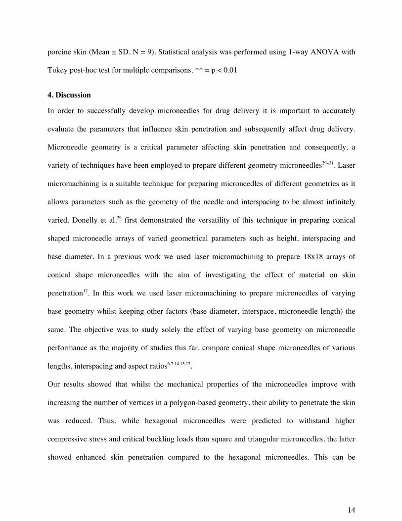
porcine skin (Mean ± SD, N = 9). Statistical analysis was performed using 1-way ANOVA with
Tukey post-hoc test for multiple comparisons. ** = p < 0.01
4. Discussion
In order to successfully develop microneedles for drug delivery it is important to accurately
evaluate the parameters that influence skin penetration and subsequently affect drug delivery.
Microneedle geometry is a critical parameter affecting skin penetration and consequently, a
variety of techniques have been employed to prepare different geometry microneedles29–31. Laser
micromachining is a suitable technique for preparing microneedles of different geometries as it
allows parameters such as the geometry of the needle and interspacing to be almost infinitely
varied. Donelly et al.29 first demonstrated the versatility of this technique in preparing conical
shaped microneedle arrays of varied geometrical parameters such as height, interspacing and
base diameter. In a previous work we used laser micromachining to prepare 18x18 arrays of
conical shape microneedles with the aim of investigating the effect of material on skin
penetration12. In this work we used laser micromachining to prepare microneedles of varying
base geometry whilst keeping other factors (base diameter, interspace, microneedle length) the
same. The objective was to study solely the effect of varying base geometry on microneedle
performance as the majority of studies this far, compare conical shape microneedles of various
lengths, interspacing and aspect ratios6,7,14,15,17.
Our results showed that whilst the mechanical properties of the microneedles improve with
increasing the number of vertices in a polygon-based geometry, their ability to penetrate the skin
was reduced. Thus, while hexagonal microneedles were predicted to withstand higher
compressive stress and critical buckling loads than square and triangular microneedles, the latter
showed enhanced skin penetration compared to the hexagonal microneedles. This can be

15
arguably attributed to the sharper edges of the triangular and square microneedles more readily
initiating stratum corneum penetration.
Various invasive and non-invasive techniques have been used to image microneedle insertion in
the skin, but the “true” depth of penetration has been demonstrated by only few techniques that
include confocal microscopy12,22,23 and optical coherence tomography (OCT)15. In this study we
have demonstrated, for the first time, that good images of microneedles, and when penetrated
within the skin, can be obtained with CT scanning. Quality CT scan images can be obtained for
structures that show a high contrast in X-ray transmission, when compared to their surroundings.
Therefore, in order to enhance the contrast, the obtained microneedles were coated in gold before
being applied to the porcine skin. Alternatively, gold nanoparticles which are excellent absorbers
of X-rays could be incorporated within the microneedle’s matrix material, and offer improved
contrast for this type of CT imaging32,33.
The capability of CT scanning to produce good images of structures of micrometer size together
with the facility of cross-sectional imaging, make this technique a very useful tool for studying
the effect of structural differences on microneedle penetration. The effect of geometry on the
mechanical strength, and in particular, on the maximum buckling force, has been compared for
microneedles of square and conical base geometries. However, the microneedle length was not
kept constant for these two different geometries34. The maximum buckling force for
microneedles with square base geometries, was lower than for microneedles with circular base
geometries which, implies that microneedles with square bases will fail first, due to buckling.
However, this geometry effect, becomes minimal at needle lengths greater than 1200 μm. At
such lengths, the maximum buckling force is similar for both the square and conical
microneedles. In our simulations, we observed a similar trend in which the maximum buckling
16
force increases with the number of vertices in the polygon base (Figure 1A). In other words, the
buckling force increases from triangular, to square and hexagonal. In a separate study13,
pyramidal microneedles with square bases, demonstrated skin penetration depths equal to one
third of the microneedle shaft length, which is in agreement with our data shown in Figure 8. Our
study undertook a comparative analysis of changing the microneedle cross-sectional shape, while
keeping all other factors such as, needle-to-needle spacing and needle length, constant. Data
from the penetration experiments showed that pyramidal microneedles with triangular and square
bases, exhibited higher penetration depths, of up to one third of that of the microneedle shaft
length, compared to microneedles with hexagonal base, whose penetration depth was found to be
approximately one fifth of the microneedle shaft length. As the number of vertices increases, the
microneedles are predicted to have better mechanical properties, i.e. hexagonal versus triangular
base. However, the latter, show enhanced penetration depth. We therefore suggest, that square
pyramidal microneedles may offer a good compromise between penetration depth and
mechanical strength.
4. Conclusions
This study included a systematic analysis of the effects of microneedle base geometry on their
structural characteristics and skin penetration properties. Regular polygons with increasing
number of vertices were used as the microneedle base geometry, whereas the microneedle length
and needle-to-needle spacing were kept constant. A laser-enabled micromoulding technique was
used to prepare 3x3 arrays of microneedles, with varying base geometries, and for the first time,
computerized tomography (CT) scanning was used to image microneedle penetration into
excised porcine skin. Simulation studies showed a linear dependence of the mechanical strength
of microneedles, to the number of vertices in the polygon geometry of the microneedle base. The

17
microneedles with triangular base were predicted to have the highest stress distribution.
However, CT scanning results showed increased in situ penetration depths for the microneedles
with triangular and square bases, when compared to those with a hexagonal base. This leads to
the conclusion that microneedles with square bases can offer a good compromise between
mechanical strength and skin penetration. Furthermore, this study demonstrated that CT scanning
can be a powerful and reliable technique for studying the penetration characteristics of
microneedles.
Acknowledgement
The assistance of Dr Ovidiu Novac with SEM is gratefully acknowledged. This study was
supported by the Marie Curie Industry Academia Partnerships and Pathways FP7-PEOPLE-
2009-IAPP-251630 grant, HIPODERM, the EPSRC Loan pool, and the Cardiff Nanoscience
Initiative.
REFERENCES
(1) Prausnitz, M. R. Microneedles for Transdermal Drug Delivery. Adv. Drug Deliv. Rev. 2004, 56 (5), 581–587.
(2) Kim, Y.-C.; Park, J.-H.; Prausnitz, M. R. Microneedles for Drug and Vaccine Delivery. Adv. Drug Deliv. Rev. 2012, 64 (14), 1547–1568.
(3) Quinn, H. L.; Kearney, M.-C.; Courtenay, A. J.; McCrudden, M. T. C.; Donnelly, R. F. The Role of Microneedles for Drug and Vaccine Delivery. Expert Opin. Drug Deliv. 2014, 11 (11), 1769–1780.
(4) Ita, K. Transdermal Delivery of Drugs with Microneedles: Strategies and Outcomes. J. Drug Deliv. Sci. Technol. 2015, 29, 16–23.
(5) Groves, R. B.; Coulman, S. A.; Birchall, J. C.; Evans, S. L. Quantifying the Mechanical Properties of Human Skin to Optimise Future Microneedle Device Design. Comput. Methods Biomech. Biomed. Engin. 2012, 15 (1), 73–82.
(6) Oh, J.-H.; Park, H.-H.; Do, K.-Y.; Han, M.; Hyun, D.-H.; Kim, C.-G.; Kim, C.-H.; Lee, S. S.; Hwang, S.-J.; Shin, S.-C.; Cho, C.-W. Influence of the Delivery Systems Using a Microneedle Array on the Permeation of a Hydrophilic Molecule, Calcein. Eur. J. Pharm. Biopharm. Off. J. Arbeitsgemeinschaft Für Pharm. Verfahrenstechnik EV 2008, 69 (3), 1040–1045.
(7) Yan, G.; Warner, K. S.; Zhang, J.; Sharma, S.; Gale, B. K. Evaluation Needle Length and Density of Microneedle Arrays in the Pretreatment of Skin for Transdermal Drug Delivery. Int. J. Pharm. 2010, 391 (1-2), 7–12.

18
(8) Al-Qallaf, B.; Das, D. B. Optimizing Microneedle Arrays to Increase Skin Permeability for Transdermal Drug Delivery. Ann. N. Y. Acad. Sci. 2009, 1161, 83–94.
(9) Teo, M. A. L.; Shearwood, C.; Ng, K. C.; Lu, J.; Moochhala, S. In Vitro and in Vivo Characterization of MEMS Microneedles. Biomed. Microdevices 2005, 7 (1), 47–52.
(10) Romgens, A. M.; Bader, D. L.; Bouwstra, J.; Baaijens, F. P. T. Monitoring the Penetration Process of Single Microneedles with Varying Tip Diameters. J. Mech. Behav. Biomed. Mater. 2014, 40, 397–405.
(11) Park, J.-H.; Allen, M. G.; Prausnitz, M. R. Biodegradable Polymer Microneedles: Fabrication, Mechanics and Transdermal Drug Delivery. J. Controlled Release 2005, 104 (1), 51–66.
(12) Loizidou, E. Z.; Williams, N. A.; Barrow, D. A.; Eaton, M. J.; McCrory, J.; Evans, S. L.; Allender, C. J. Structural Characterisation and Transdermal Delivery Studies on Sugar Microneedles: Experimental and Finite Element Modelling Analyses. Eur. J. Pharm. Biopharm. Off. J. Arbeitsgemeinschaft Für Pharm. Verfahrenstechnik EV 2015, 89, 224–231.
(13) Lee, J. W.; Park, J.-H.; Prausnitz, M. R. Dissolving Microneedles for Transdermal Drug Delivery. Biomaterials 2008, 29 (13), 2113–2124.
(14) Olatunji, O.; Das, D. B.; Garland, M. J.; Belaid, L.; Donnelly, R. F. Influence of Array Interspacing on the Force Required for Successful Microneedle Skin Penetration: Theoretical and Practical Approaches. J. Pharm. Sci. 2013, 102 (4), 1209–1221.
(15) Donnelly, R. F.; Garland, M. J.; Morrow, D. I. J.; Migalska, K.; Singh, T. R. R.; Majithiya, R.; Woolfson, A. D. Optical Coherence Tomography Is a Valuable Tool in the Study of the Effects of Microneedle Geometry on Skin Penetration Characteristics and in-Skin Dissolution. J. Control. Release Off. J. Control. Release Soc. 2010, 147 (3), 333–341.
(16) van der Maaden, K.; Varypataki, E. M.; Yu, H.; Romeijn, S.; Jiskoot, W.; Bouwstra, J. Parameter Optimization toward Optimal Microneedle-Based Dermal Vaccination. Eur. J. Pharm. Biopharm. 2014, 64, 18–25.
(17) Kochhar, J. S.; Quek, T. C.; Soon, W. J.; Choi, J.; Zou, S.; Kang, L. Effect of Microneedle Geometry and Supporting Substrate on Microneedle Array Penetration into Skin. J. Pharm. Sci. 2013, 102 (11), 4100–4108.
(18) Vemulapalli, V.; Bai, Y.; Kalluri, H.; Herwadkar, A.; Kim, H.; Davis, S. P.; Friden, P. M.; Banga, A. K. In Vivo Iontophoretic Delivery of Salmon Calcitonin across Microporated Skin. J. Pharm. Sci. 2012, 101 (8), 2861–2869.
(19) Li, G.; Badkar, A.; Kalluri, H.; Banga, A. K. Microchannels Created by Sugar and Metal Microneedles: Characterization by Microscopy, Macromolecular Flux and Other Techniques. J. Pharm. Sci. 2010, 99 (4), 1931–1941.
(20) Groves, R. B.; Coulman, S. A.; Birchall, J. C.; Evans, S. L. An Anisotropic, Hyperelastic Model for Skin: Experimental Measurements, Finite Element Modelling and Identification of Parameters for Human and Murine Skin. J. Mech. Behav. Biomed. Mater. 2013, 18, 167–180.
(21) Giannakopoulos, A. E.; Panagiotopoulos, D. I. Conical Indentation of Incompressible Rubber-like Materials. Int. J. Solids Struct. 46 (6), 1436–1447.
(22) Bal, S. M.; Kruithof, A. C.; Zwier, R.; Dietz, E.; Bouwstra, J. A.; Lademann, J.; Meinke, M. C. Influence of Microneedle Shape on the Transport of a Fluorescent Dye into Human Skin in Vivo. J. Control. Release Off. J. Control. Release Soc. 2010, 147 (2), 218–224.

19
(23) Kolli, C. S.; Banga, A. K. Characterization of Solid Maltose Microneedles and Their Use for Transdermal Delivery. Pharm. Res. 2008, 25 (1), 104–113.
(24) Coulman, S. A.; Birchall, J. C.; Alex, A.; Pearton, M.; Hofer, B.; O’Mahony, C.; Drexler, W.; Považay, B. In Vivo, in Situ Imaging of Microneedle Insertion into the Skin of Human Volunteers Using Optical Coherence Tomography. Pharm. Res. 2011, 28 (1), 66–81.
(25) Enfield, J.; O’Connell, M.-L.; Lawlor, K.; Jonathan, E.; O’Mahony, C.; Leahy, M. In-Vivo Dynamic Characterization of Microneedle Skin Penetration Using Optical Coherence Tomography. J. Biomed. Opt. 2010, 15 (4), 046001.
(26) Cnudde, V.; Boone, M. N. High-Resolution X-Ray Computed Tomography in Geosciences: A Review of the Current Technology and Applications. Earth-Sci. Rev. 2013, 123, 1–17.
(27) Geerligs, M.; van Breemen, L.; Peters, G.; Ackermans, P.; Baaijens, F.; Oomens, C. In Vitro Indentation to Determine the Mechanical Properties of Epidermis. J. Biomech. 2011, 44 (6), 1176–1181.
(28) Hara, Y.; Masuda, Y.; Hirao, T.; Yoshikawa, N. The Relationship between the Young’s Modulus of the Stratum Corneum and Age: A Pilot Study. Skin Res. Technol. Off. J. Int. Soc. Bioeng. Skin ISBS Int. Soc. Digit. Imaging Skin ISDIS Int. Soc. Skin Imaging ISSI 2013, 19 (3), 339–345.
(29) Donnelly, R. F.; Majithiya, R.; Singh, T. R. R.; Morrow, D. I. J.; Garland, M. J.; Demir, Y. K.; Migalska, K.; Ryan, E.; Gillen, D.; Scott, C. J.; Woolfson, A. D. Design, Optimization and Characterisation of Polymeric Microneedle Arrays Prepared by a Novel Laser-Based Micromoulding Technique. Pharm. Res. 2011, 28 (1), 41–57.
(30) McAllister, D. V.; Wang, P. M.; Davis, S. P.; Park, J.-H.; Canatella, P. J.; Allen, M. G.; Prausnitz, M. R. Microfabricated Needles for Transdermal Delivery of Macromolecules and Nanoparticles: Fabrication Methods and Transport Studies. Proc. Natl. Acad. Sci. U. S. A. 2003, 100 (24), 13755–13760.
(31) Moga, K. A.; Bickford, L. R.; Geil, R. D.; Dunn, S. S.; Pandya, A. A.; Wang, Y.; Fain, J. H.; Archuleta, C. F.; O’Niell, A. T.; DeSimone, J. M. Rapidly–Dissolvable Microneedle Patches Via a Highly Scalable and Reproducible Soft Lithography Approach. Adv. Mater. 2013, 25, 5060–5066.
(32) Ahn, S.; Jung, S. Y.; Lee, S. J. Gold Nanoparticle Contrast Agents in Advanced X-Ray Imaging Technologies. Molecules 2013, 18 (5), 5858–5890.
(33) Popovtzer, R.; Agrawal, A.; Kotov, N. A.; Popovtzer, A.; Balter, J.; Carey, T. E.; Kopelman, R. Targeted Gold Nanoparticles Enable Molecular CT Imaging of Cancer. Nano Lett. 2008, 8 (12), 4593–4596.
(34) Aggarwal, P.; Johnston, C. R. Geometrical Effects in Mechanical Characterizing of Microneedle for Biomedical Applications. Sens. Actuators B Chem. 2004, 102 (2), 226–234.


