VXC - E 1
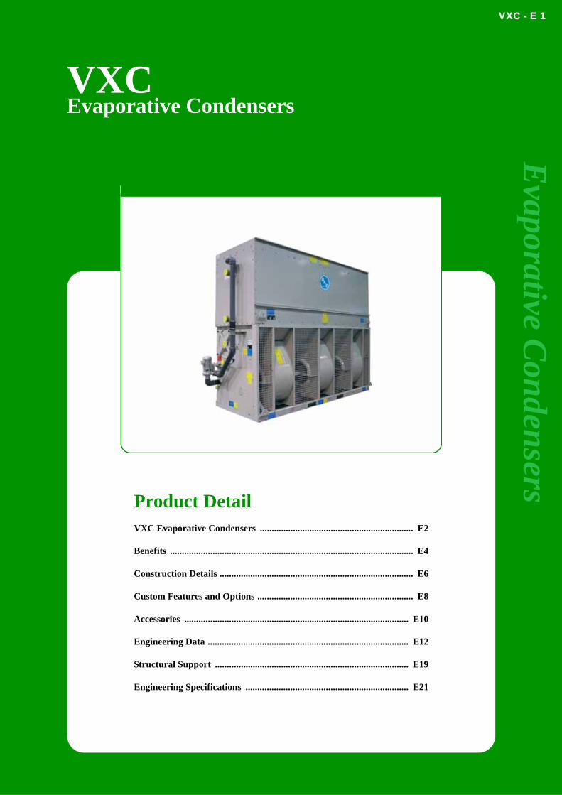
VXC
Evaporative CondensersEvaporative C
ondensers
Product DetailVXC Evaporative Condensers ................................................................. E2
Benefits ....................................................................................................... E4
Construction Details .................................................................................. E6
Custom Features and Options .................................................................. E8
Accessories ............................................................................................... E10
Engineering Data ..................................................................................... E12
Structural Support .................................................................................. E19
Engineering Specifications ..................................................................... E21

VXC - E 2
VX
C
VXC Evaporative CondensersCapacitySingle Model Capacity:VXC : 50 – 6470 Nominal R717 kW’s
VXC-C : 880 – 1720 Nominal R717 kW’s
General DescriptionVXC Evaporative Condensers deliver fully rated thermal performance over a wide range of heat rejection and temperature requirements for various refrigerants. VXC and VXC-C models can be installed indoors and minimize sound levels. VXC-C models are designed to fit in standard dry van containers to minimize ocean freight costs. The Series VX occupies minimum floor space, provides year-round operating reliability and is ideal for sound sensitive applications.
Key FeaturesSuitable for indoor and outdoor installations
Low sound
Low ocean freight costs (VXC-C)
Single side air inlet
Low energy consumption
Low installed cost
Easy maintenance
Reliable year-round operation
Long service life
Wide capacity range
PED 97/23/EC coil design
Baltimore Aircoil
VXC - E 3
Evaporative C
ondensers
... because temperature matters
VXC - E 4
VX
C
BenefitsWide Capacity RangeEvaporative condenser capacity - The evaporative condensers are available in a broad range of unit capacities, with small capacity increments to permit close matching of unit size to design load. The VX line offers the widest selection of evaporative condensers in the industry to meet virtually every installation and application need.
Installation and Application FlexibilityIndoor Installations – Centrifugal fans can overcome the static pressure imposed by external ductwork, allowing these units to be installed indoors.
Low SoundCentrifugal Fan - Centrifugal fans have inherently low sound characteristics.
Single Side Air Inlet - Particularly sound-sensitive areas can be accommodated by facing the quiet side (back panel) to the sound-sensitive direction.
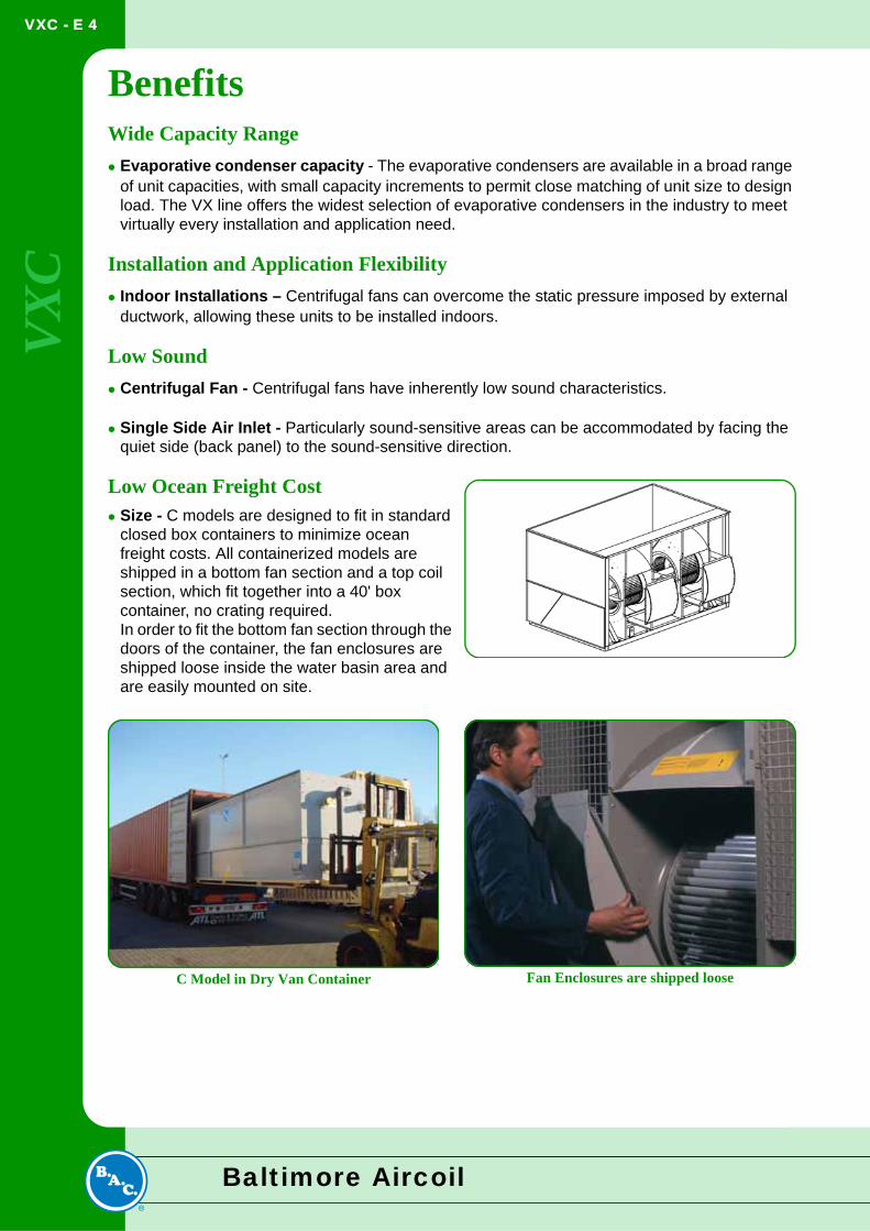
Low Ocean Freight CostSize - C models are designed to fit in standard closed box containers to minimize ocean freight costs. All containerized models are shipped in a bottom fan section and a top coil section, which fit together into a 40' box container, no crating required.In order to fit the bottom fan section through the doors of the container, the fan enclosures are shipped loose inside the water basin area and are easily mounted on site.
C Model in Dry Van Container Fan Enclosures are shipped loose
Baltimore Aircoil
VXC - E 5
Evaporative C
ondensers
Low Energy ConsumptionEvaporative Cooling Equipment minimizes the energy consumption of the entire system because it provides lower operating temperatures. The owner saves money while conserving natural resources and reducing environmental impact.
Evaporative Condensers provide lower condensing temperatures and can offer significant kW savings over conventional air-cooled and water-cooled condensing systems.
Low Installed CostSupport – All models mount directly on two parallel I-beams (supplied by others) and ship complete with motors and drives, factory-installed and aligned.
Modular Design – Large models ship in multiple sections to minimize the size and weight of the heaviest lift, allowing for the use of smaller, less costly cranes.
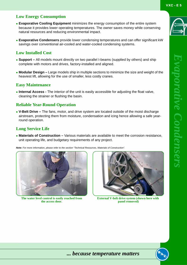
Easy MaintenanceInternal Access - The interior of the unit is easily accessible for adjusting the float valve, cleaning the strainer or flushing the basin.
Reliable Year-Round OperationV-Belt Drive – The fans, motor, and drive system are located outside of the moist discharge airstream, protecting them from moisture, condensation and icing hence allowing a safe year-round operation.
Long Service LifeMaterials of Construction – Various materials are available to meet the corrosion resistance, unit operating life, and budgetary requirements of any project.
Note: For more information, please refer to the section “Technical Resources, Materials of Construction”.
The water level control is easily reached from the access door.
External V-belt drive system (shown here with panel removed)
... because temperature matters
VXC - E 6
VX
C
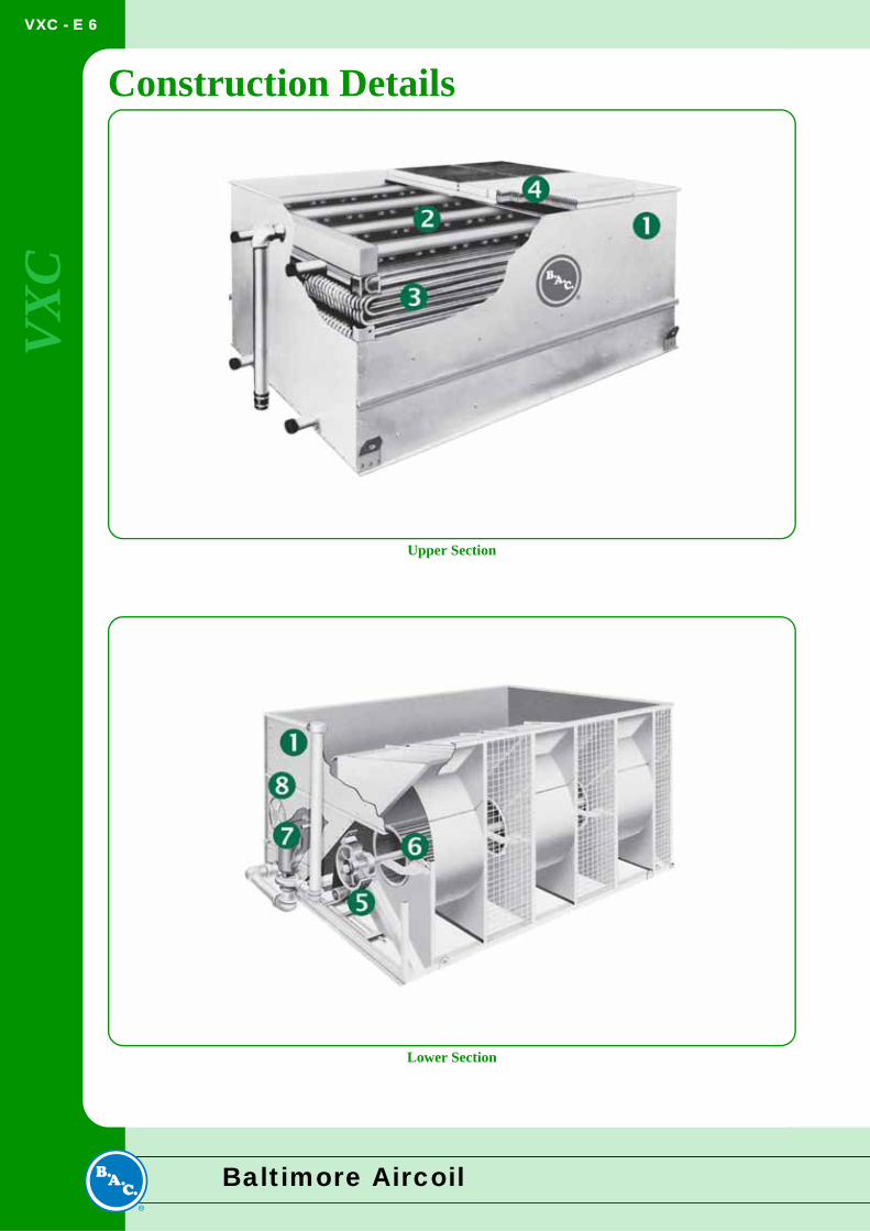
Construction DetailsUpper Section
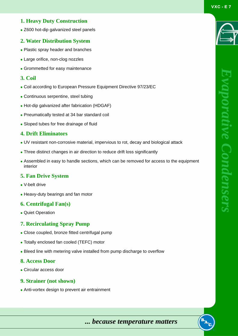
Lower Section
Baltimore Aircoil
VXC - E 7
Evaporative C
ondensers
1. Heavy Duty ConstructionZ600 hot-dip galvanized steel panels
2. Water Distribution SystemPlastic spray header and branches
Large orifice, non-clog nozzles
Grommetted for easy maintenance
3. CoilCoil according to European Pressure Equipment Directive 97/23/EC
Continuous serpentine, steel tubing
Hot-dip galvanized after fabrication (HDGAF)
Pneumatically tested at 34 bar standard coil
Sloped tubes for free drainage of fluid
4. Drift EliminatorsUV resistant non-corrosive material, impervious to rot, decay and biological attack
Three distinct changes in air direction to reduce drift loss significantly
Assembled in easy to handle sections, which can be removed for access to the equipment interior
5. Fan Drive SystemV-belt drive
Heavy-duty bearings and fan motor
6. Centrifugal Fan(s)Quiet Operation
7. Recirculating Spray PumpClose coupled, bronze fitted centrifugal pump
Totally enclosed fan cooled (TEFC) motor
Bleed line with metering valve installed from pump discharge to overflow
8. Access DoorCircular access door
9. Strainer (not shown)Anti-vortex design to prevent air entrainment
... because temperature matters
VXC - E 8
VX
C
Custom Features and OptionsConstruction OptionsStandard Construction:Steel panels and structural elements are constructed of Z600 heavy-gauge hot-dip galvanized steel protected with the Baltiplus Corrosion Protection on the outside of the unit.
Optional BALTIBOND® Corrosion Protection System:The BALTIBOND®
Corrosion Protection System, a hybrid polymer coating used to extend equipment life, is applied before assembly to all hot-dip galvanized steel components of the unit.
Optional Stainless Steel Construction:Steel panels and structural elements are constructed of stainless steel either type 304 or 316.
Optional Water-Contact Stainless Steel Cold Water Basin:A cost-effective alternative to an all stainless steel unit. The critical components in the cold water basin and the cold water basin itself are provided in stainless steel. The remaining components are protected with the BALTIBOND®
Corrosion Protection System.
Note: See section Technical Resources, Material of Construction for more details on the materials described above.
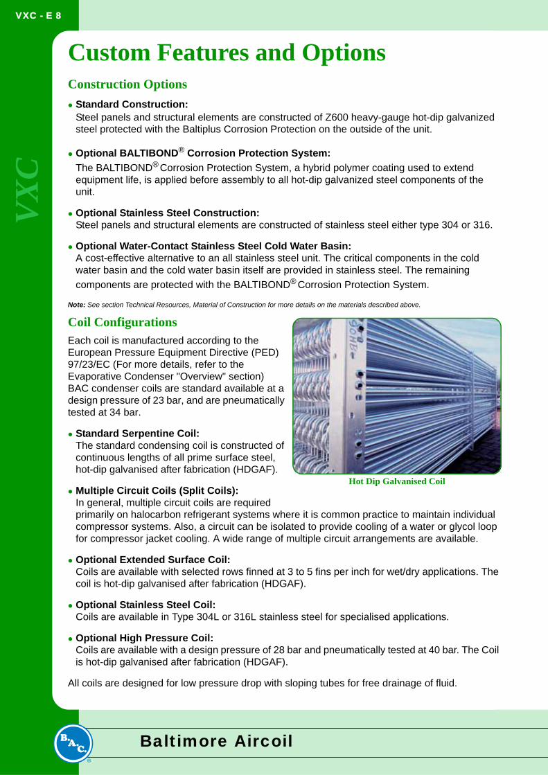
Coil ConfigurationsEach coil is manufactured according to the European Pressure Equipment Directive (PED) 97/23/EC (For more details, refer to the Evaporative Condenser "Overview" section)BAC condenser coils are standard available at a design pressure of 23 bar, and are pneumatically tested at 34 bar.
Standard Serpentine Coil:The standard condensing coil is constructed of continuous lengths of all prime surface steel, hot-dip galvanised after fabrication (HDGAF).
Multiple Circuit Coils (Split Coils):In general, multiple circuit coils are required primarily on halocarbon refrigerant systems where it is common practice to maintain individual compressor systems. Also, a circuit can be isolated to provide cooling of a water or glycol loop for compressor jacket cooling. A wide range of multiple circuit arrangements are available.
Optional Extended Surface Coil:Coils are available with selected rows finned at 3 to 5 fins per inch for wet/dry applications. The coil is hot-dip galvanised after fabrication (HDGAF).
Optional Stainless Steel Coil:Coils are available in Type 304L or 316L stainless steel for specialised applications.
Optional High Pressure Coil:Coils are available with a design pressure of 28 bar and pneumatically tested at 40 bar. The Coil is hot-dip galvanised after fabrication (HDGAF).
All coils are designed for low pressure drop with sloping tubes for free drainage of fluid.
Hot Dip Galvanised Coil
Baltimore Aircoil
VXC - E 9
Evaporative C
ondensers
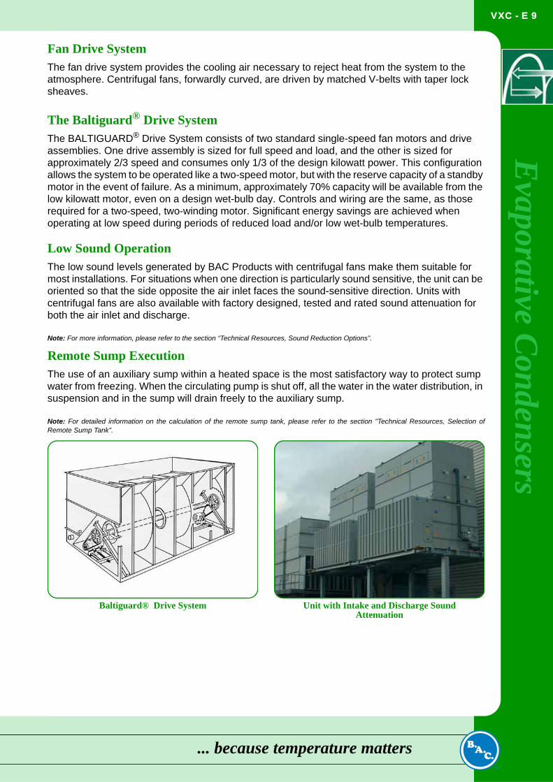
Fan Drive SystemThe fan drive system provides the cooling air necessary to reject heat from the system to the atmosphere. Centrifugal fans, forwardly curved, are driven by matched V-belts with taper lock sheaves.The Baltiguard® Drive SystemThe BALTIGUARD® Drive System consists of two standard single-speed fan motors and drive assemblies. One drive assembly is sized for full speed and load, and the other is sized for approximately 2/3 speed and consumes only 1/3 of the design kilowatt power. This configuration allows the system to be operated like a two-speed motor, but with the reserve capacity of a standby motor in the event of failure. As a minimum, approximately 70% capacity will be available from the low kilowatt motor, even on a design wet-bulb day. Controls and wiring are the same, as those required for a two-speed, two-winding motor. Significant energy savings are achieved when operating at low speed during periods of reduced load and/or low wet-bulb temperatures.
Low Sound OperationThe low sound levels generated by BAC Products with centrifugal fans make them suitable for most installations. For situations when one direction is particularly sound sensitive, the unit can be oriented so that the side opposite the air inlet faces the sound-sensitive direction. Units with centrifugal fans are also available with factory designed, tested and rated sound attenuation for both the air inlet and discharge.
Note: For more information, please refer to the section “Technical Resources, Sound Reduction Options”.
Remote Sump ExecutionThe use of an auxiliary sump within a heated space is the most satisfactory way to protect sump water from freezing. When the circulating pump is shut off, all the water in the water distribution, in suspension and in the sump will drain freely to the auxiliary sump.
Note: For detailed information on the calculation of the remote sump tank, please refer to the section "Technical Resources, Selection ofRemote Sump Tank".
Baltiguard® Drive System Unit with Intake and Discharge Sound Attenuation
... because temperature matters
VXC - E 10
VX
C
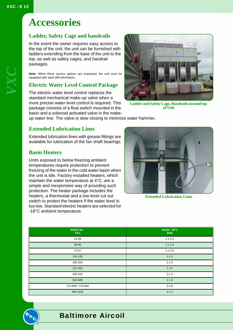
AccessoriesLadder, Safety Cage and handrailsIn the event the owner requires easy access to the top of the unit, the unit can be furnished with ladders extending from the base of the unit to the top, as well as safety cages, and handrail packages.Note: When these access options are employed, the unit must beequipped with steel drift eliminators.
Electric Water Level Control PackageThe electric water level control replaces the standard mechanical make-up valve when a more precise water level control is required. This package consists of a float switch mounted in the basin and a solenoid activated valve in the make-up water line. The valve is slow closing to minimize water hammer.
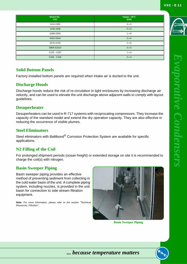
Extended Lubrication LinesExtended lubrication lines with grease fittings are available for lubrication of the fan shaft bearings.
Basin HeatersUnits exposed to below freezing ambient temperatures require protection to prevent freezing of the water in the cold water basin when the unit is idle. Factory-installed heaters, which maintain the water temperature at 4°C, are a simple and inexpensive way of providing such protection. The heater package includes the heaters, a thermostat and a low level cut out switch to protect the heaters if the water level is too low. Standard electric heaters are selected for -18°C ambient temperature.
Model No. VXC
Heater -18°C(kW)
14-28 1 x 1,5
36-65 1 x 1,5
72-97 1 x 2,5
110-135 1 x 3
150-205 1 x 4
221-454 1 x 6
495-516 2 x 4
562-680 2 x 5
714-908 / 715-804 2 x 6
990-1032 4 x 4
Ladder and Safety Cage, Handrails around top of Unit
Extended Lubrication Lines
Baltimore Aircoil
VXC - E 11
Evaporative C
ondensers
Solid Bottom PanelsFactory-installed bottom panels are required when intake air is ducted to the unit.
Discharge HoodsDischarge hoods reduce the risk of re-circulation in tight enclosures by increasing discharge air velocity, and can be used to elevate the unit discharge above adjacent walls to comply with layout guidelines.
DesuperheaterDesuperheaters can be used in R-717 systems with reciprocating compressors. They increase the capacity of the standard model and extend the dry operation capacity. They are also effective in reducing the occurrence of visible plumes.
Steel EliminatorsSteel eliminators with Baltibond® Corrosion Protection System are available for specific applications.
N2 Filling of the CoilFor prolonged shipment periods (ocean freight) or extended storage on site it is recommended to charge the coil(s) with nitrogen.
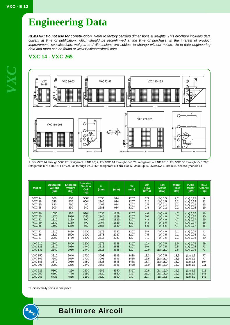
Basin Sweeper PipingBasin sweeper piping provides an effective method of preventing sediment from collecting in the cold water basin of the unit. A complete piping system, including nozzles, is provided in the unit basin for connection to side stream filtration equipment.
Note: For more information, please refer to the section "TechnicalResources, Filtration".
1124-1360 4 x 5
1430-1608 4 x 6
S288-S350 1 x 6
S403-S504 2 x 4
S576-S700 2 x 6
S806-S1010 4 x 4
C220 - C287 1 x 6
C325 - C426 2 x 4
Model No. VXC
Heater -18°C(kW)
Basin Sweeper Piping
... because temperature matters
VXC - E 12
VX
C
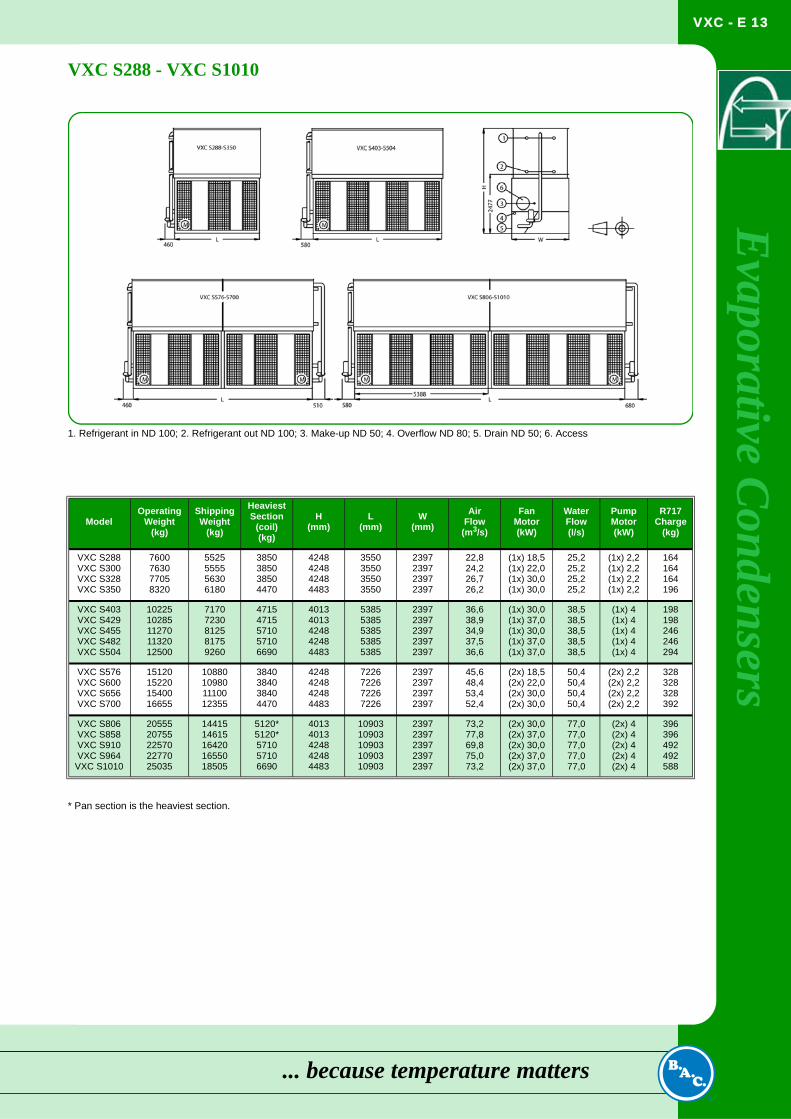
Engineering DataREMARK: Do not use for construction. Refer to factory certified dimensions & weights. This brochure includes datacurrent at time of publication, which should be reconfirmed at the time of purchase. In the interest of productimprovement, specifications, weights and dimensions are subject to change without notice. Up-to-date engineeringdata and more can be found at www.BaltimoreAircoil.com.VXC 14 - VXC 265
* Unit normally ships in one piece.
ModelOperating
Weight(kg)
ShippingWeight
(kg)
HeaviestSection
Coil(kg)
H(mm)
L(mm)
W(mm)
AirFlow(m3/s)
FanMotor(kW)
WaterFlow(l/s)
PumpMotor(kW)
R717Charge
(kg)
VXC 14VXC 18VXC 25VXC 28
660740830900
600670760830
580*660*480540
2035224524672683
914914914914
1207120712071207
2,32,22,52,4
(1x) 1,5(1x) 1,5(1x) 2,2(1x) 2,2
2,22,22,22,2
(1x) 0,25(1x) 0,25(1x) 0,25(1x) 0,25
9111519
VXC 36VXC 45VXC 52VXC 59VXC 65
10501170131013301500
9201030116011801330
920*1030*700700860
20352245246724672683
18291829182918291829
12071207120712071207
4,65,04,85,35,5
(1x) 4,0(1x) 4,0(1x) 4,0(1x) 5,5(1x) 5,5
4,74,74,74,74,7
(1x) 0,37(1x) 0,37(1x) 0,37(1x) 0,37(1x) 0,37
1620292936
VXC 72VXC 86VXC 97
181018202080
149015001730
100010001200
257825782813
273727372737
120712071207
5,87,57,1
(1x) 4,0(1x) 7,5(1x) 7,5
7,17,17,1
(1x) 0,75(1x) 0,75(1x) 0,75
414150
VXC 110VXC 125VXC 135
224025102540
180020502080
120014401440
257828132813
365836583658
120712071207
10,49,9
10,9
(1x) 7,5(1x) 7,5(1x) 11,0
9,59,59,5
(1x) 0,75(1x) 0,75(1x) 0,75
597373
VXC 150VXC 166VXC 185VXC 205
3210324036703980
2640267029503255
1720172019802240
3093309333283563
3645364536453645
1438143814381438
13,315,815,716,9
(1x) 7,5(1x) 11,0(1x) 11,0(1x) 15,0
13,913,913,913,9
(1x) 1,5(1x) 1,5(1x) 1,5(1x) 1,5
7777104111
VXC 221VXC 250VXC 265
586063906435
425047704815
263031503150
358538203820
355035503550
239723972397
20,821,222,7
(1x) 15,0(1x) 15,0(1x) 18,5
19,219,219,2
(1x) 2,2(1x) 2,2(1x) 2,2
118146146
1. For VXC 14 through VXC 28: refrigerant in ND 80; 2. For VXC 14 through VXC 28: refrigerant out ND 80: 3. For VXC 36 through VXC 265: refrigerant in ND 100; 4. For VXC 36 through VXC 265: refrigerant out ND 100; 5. Make-up; 6. Overflow; 7. Drain; 8. Access (models 14
Baltimore Aircoil
VXC - E 13
Evaporative C
ondensers
VXC S288 - VXC S1010* Pan section is the heaviest section.
ModelOperating
Weight(kg)
ShippingWeight
(kg)
HeaviestSection
(coil)(kg)
H(mm)
L(mm)
W(mm)
AirFlow
(m3/s)
FanMotor(kW)
WaterFlow(l/s)
PumpMotor(kW)
R717Charge
(kg)
VXC S288VXC S300VXC S328VXC S350
7600763077058320
5525555556306180
3850385038504470
4248424842484483
3550355035503550
2397239723972397
22,824,226,726,2
(1x) 18,5(1x) 22,0(1x) 30,0(1x) 30,0
25,225,225,225,2
(1x) 2,2(1x) 2,2(1x) 2,2(1x) 2,2
164164164196
VXC S403VXC S429VXC S455VXC S482VXC S504
1022510285112701132012500
71707230812581759260
47154715571057106690
40134013424842484483
53855385538553855385
23972397239723972397
36,638,934,937,536,6
(1x) 30,0(1x) 37,0(1x) 30,0(1x) 37,0(1x) 37,0
38,538,538,538,538,5
(1x) 4(1x) 4(1x) 4(1x) 4(1x) 4
198198246246294
VXC S576VXC S600VXC S656VXC S700
15120152201540016655
10880109801110012355
3840384038404470
4248424842484483
7226722672267226
2397239723972397
45,648,453,452,4
(2x) 18,5(2x) 22,0(2x) 30,0(2x) 30,0
50,450,450,450,4
(2x) 2,2(2x) 2,2(2x) 2,2(2x) 2,2
328328328392
VXC S806VXC S858VXC S910VXC S964
VXC S1010
2055520755225702277025035
1441514615164201655018505
5120*5120*571057106690
40134013424842484483
1090310903109031090310903
23972397239723972397
73,277,869,875,073,2
(2x) 30,0(2x) 37,0(2x) 30,0(2x) 37,0(2x) 37,0
77,077,077,077,077,0
(2x) 4(2x) 4(2x) 4(2x) 4(2x) 4
396396492492588
1. Refrigerant in ND 100; 2. Refrigerant out ND 100; 3. Make-up ND 50; 4. Overflow ND 80; 5. Drain ND 50; 6. Access
... because temperature matters
VXC - E 14
VX
C
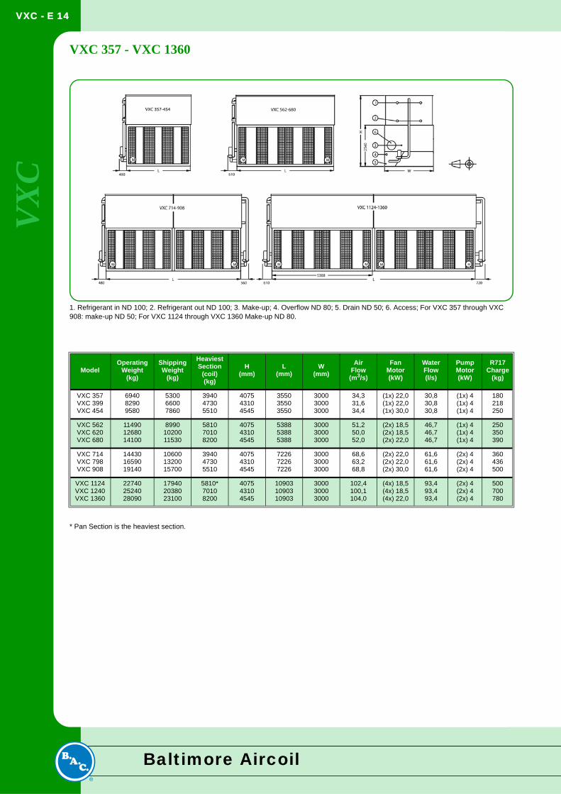
VXC 357 - VXC 1360* Pan Section is the heaviest section.
ModelOperating
Weight(kg)
ShippingWeight
(kg)
HeaviestSection
(coil)(kg)
H(mm)
L(mm)
W(mm)
AirFlow(m3/s)
FanMotor(kW)
WaterFlow(l/s)
PumpMotor(kW)
R717Charge
(kg)
VXC 357VXC 399VXC 454
694082909580
530066007860
394047305510
407543104545
355035503550
300030003000
34,331,634,4
(1x) 22,0(1x) 22,0(1x) 30,0
30,830,830,8
(1x) 4(1x) 4(1x) 4
180218250
VXC 562VXC 620VXC 680
114901268014100
89901020011530
581070108200
407543104545
538853885388
300030003000
51,250,052,0
(2x) 18,5(2x) 18,5(2x) 22,0
46,746,746,7
(1x) 4(1x) 4(1x) 4
250350390
VXC 714VXC 798VXC 908
144301659019140
106001320015700
394047305510
407543104545
722672267226
300030003000
68,663,268,8
(2x) 22,0(2x) 22,0(2x) 30,0
61,661,661,6
(2x) 4(2x) 4(2x) 4
360436500
VXC 1124VXC 1240VXC 1360
227402524028090
179402038023100
5810*70108200
407543104545
109031090310903
300030003000
102,4100,1104,0
(4x) 18,5(4x) 18,5(4x) 22,0
93,493,493,4
(2x) 4(2x) 4(2x) 4
500700780
1. Refrigerant in ND 100; 2. Refrigerant out ND 100; 3. Make-up; 4. Overflow ND 80; 5. Drain ND 50; 6. Access; For VXC 357 through VXC 908: make-up ND 50; For VXC 1124 through VXC 1360 Make-up ND 80.
Baltimore Aircoil
VXC - E 15
Evaporative C
ondensers
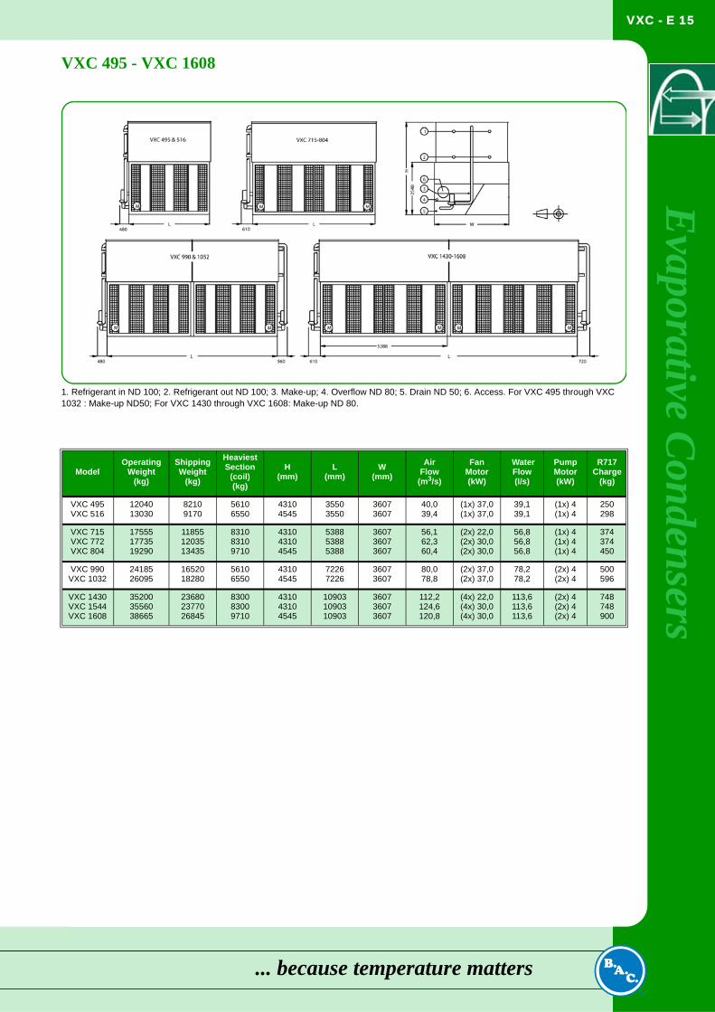
VXC 495 - VXC 1608ModelOperating
Weight(kg)
ShippingWeight
(kg)
HeaviestSection
(coil)(kg)
H(mm)
L(mm)
W(mm)
AirFlow(m3/s)
FanMotor(kW)
WaterFlow(l/s)
PumpMotor(kW)
R717Charge
(kg)
VXC 495VXC 516
1204013030
82109170
56106550
43104545
35503550
36073607
40,039,4
(1x) 37,0(1x) 37,0
39,139,1
(1x) 4(1x) 4
250298
VXC 715VXC 772VXC 804
175551773519290
118551203513435
831083109710
431043104545
538853885388
360736073607
56,162,360,4
(2x) 22,0(2x) 30,0(2x) 30,0
56,856,856,8
(1x) 4(1x) 4(1x) 4
374374450
VXC 990VXC 1032
2418526095
1652018280
56106550
43104545
72267226
36073607
80,078,8
(2x) 37,0(2x) 37,0
78,278,2
(2x) 4(2x) 4
500596
VXC 1430VXC 1544VXC 1608
352003556038665
236802377026845
830083009710
431043104545
109031090310903
360736073607
112,2124,6120,8
(4x) 22,0(4x) 30,0(4x) 30,0
113,6113,6113,6
(2x) 4(2x) 4(2x) 4
748748900
1. Refrigerant in ND 100; 2. Refrigerant out ND 100; 3. Make-up; 4. Overflow ND 80; 5. Drain ND 50; 6. Access. For VXC 495 through VXC 1032 : Make-up ND50; For VXC 1430 through VXC 1608: Make-up ND 80.
... because temperature matters
VXC - E 16
VX
C
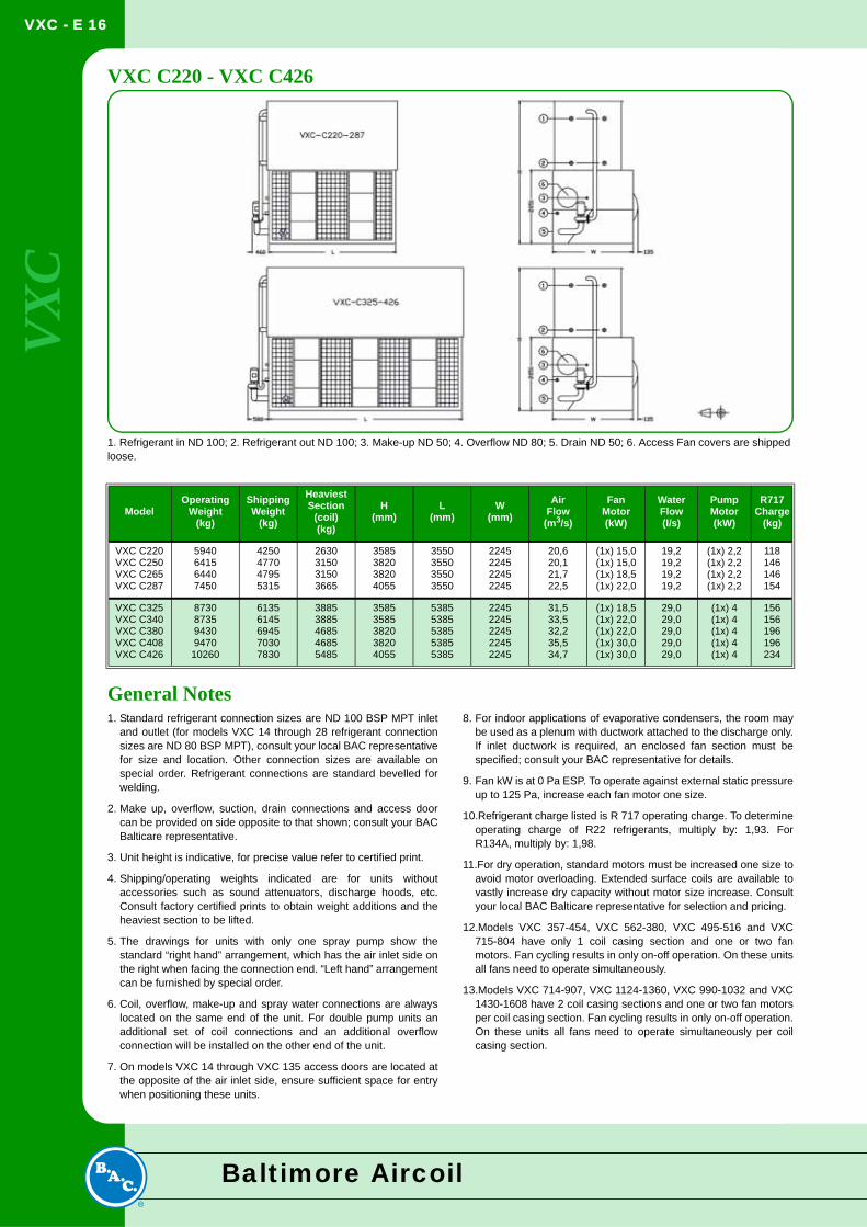
VXC C220 - VXC C426General Notes1. Standard refrigerant connection sizes are ND 100 BSP MPT inlet
and outlet (for models VXC 14 through 28 refrigerant connectionsizes are ND 80 BSP MPT), consult your local BAC representativefor size and location. Other connection sizes are available onspecial order. Refrigerant connections are standard bevelled forwelding.
2. Make up, overflow, suction, drain connections and access doorcan be provided on side opposite to that shown; consult your BACBalticare representative.
3. Unit height is indicative, for precise value refer to certified print.
4. Shipping/operating weights indicated are for units withoutaccessories such as sound attenuators, discharge hoods, etc.Consult factory certified prints to obtain weight additions and theheaviest section to be lifted.
5. The drawings for units with only one spray pump show thestandard “right hand” arrangement, which has the air inlet side onthe right when facing the connection end. “Left hand” arrangementcan be furnished by special order.
6. Coil, overflow, make-up and spray water connections are alwayslocated on the same end of the unit. For double pump units anadditional set of coil connections and an additional overflowconnection will be installed on the other end of the unit.
7. On models VXC 14 through VXC 135 access doors are located atthe opposite of the air inlet side, ensure sufficient space for entrywhen positioning these units.
8. For indoor applications of evaporative condensers, the room maybe used as a plenum with ductwork attached to the discharge only.If inlet ductwork is required, an enclosed fan section must bespecified; consult your BAC representative for details.
9. Fan kW is at 0 Pa ESP. To operate against external static pressureup to 125 Pa, increase each fan motor one size.
10.Refrigerant charge listed is R 717 operating charge. To determineoperating charge of R22 refrigerants, multiply by: 1,93. ForR134A, multiply by: 1,98.
11.For dry operation, standard motors must be increased one size toavoid motor overloading. Extended surface coils are available tovastly increase dry capacity without motor size increase. Consultyour local BAC Balticare representative for selection and pricing.
12.Models VXC 357-454, VXC 562-380, VXC 495-516 and VXC715-804 have only 1 coil casing section and one or two fanmotors. Fan cycling results in only on-off operation. On these unitsall fans need to operate simultaneously.
13.Models VXC 714-907, VXC 1124-1360, VXC 990-1032 and VXC1430-1608 have 2 coil casing sections and one or two fan motorsper coil casing section. Fan cycling results in only on-off operation.On these units all fans need to operate simultaneously per coilcasing section.
ModelOperating
Weight(kg)
ShippingWeight
(kg)
HeaviestSection
(coil)(kg)
H(mm)
L(mm)
W(mm)
AirFlow
(m3/s)
FanMotor(kW)
WaterFlow(l/s)
PumpMotor(kW)
R717Charge
(kg)
VXC C220VXC C250VXC C265VXC C287
5940641564407450
4250477047955315
2630315031503665
3585382038204055
3550355035503550
2245224522452245
20,620,121,722,5
(1x) 15,0(1x) 15,0(1x) 18,5(1x) 22,0
19,219,219,219,2
(1x) 2,2(1x) 2,2(1x) 2,2(1x) 2,2
118146146154
VXC C325VXC C340VXC C380VXC C408VXC C426
873087359430947010260
61356145694570307830
38853885468546855485
35853585382038204055
53855385538553855385
22452245224522452245
31,533,532,235,534,7
(1x) 18,5(1x) 22,0(1x) 22,0(1x) 30,0(1x) 30,0
29,029,029,029,029,0
(1x) 4(1x) 4(1x) 4(1x) 4(1x) 4
156156196196234
1. Refrigerant in ND 100; 2. Refrigerant out ND 100; 3. Make-up ND 50; 4. Overflow ND 80; 5. Drain ND 50; 6. Access Fan covers are shipped loose.
Baltimore Aircoil
VXC - E 17
Evaporative C
ondensers
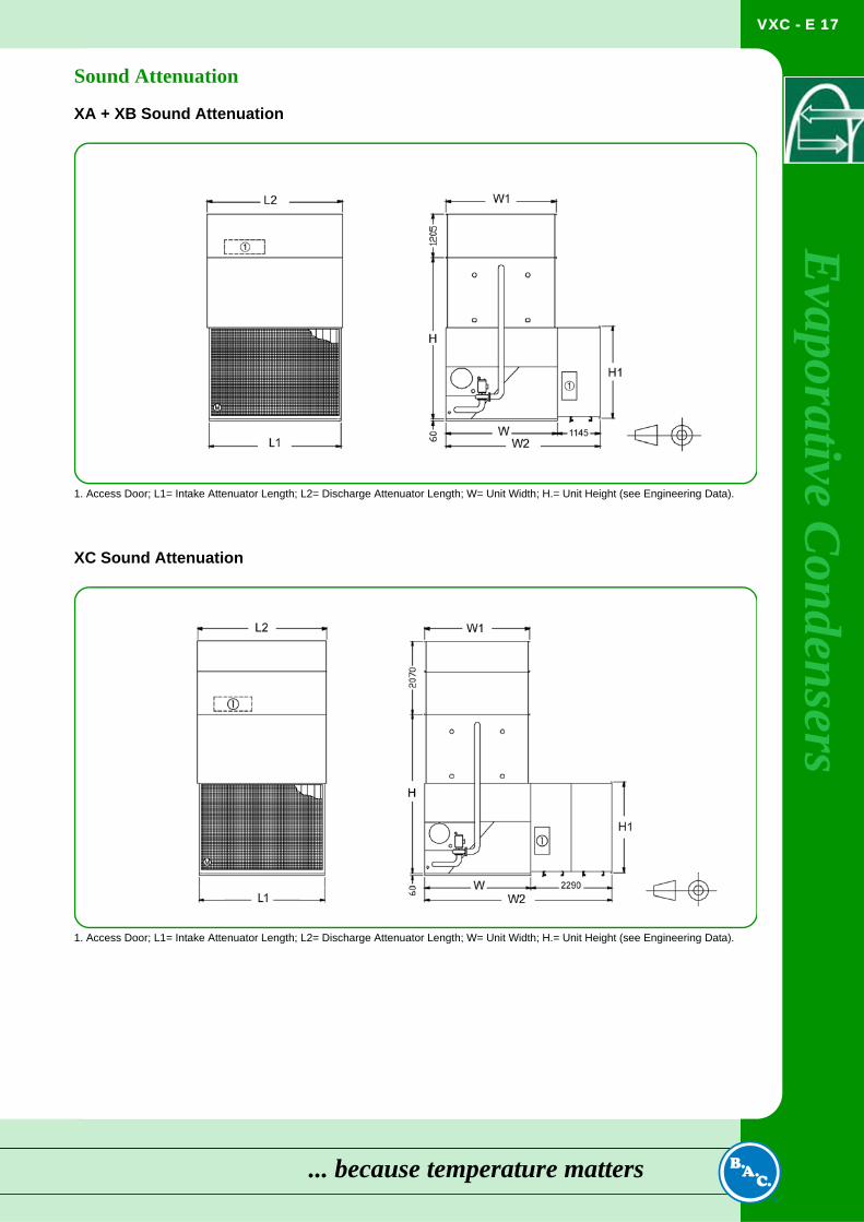
Sound AttenuationXA + XB Sound Attenuation
XC Sound Attenuation
1. Access Door; L1= Intake Attenuator Length; L2= Discharge Attenuator Length; W= Unit Width; H.= Unit Height (see Engineering Data).
1. Access Door; L1= Intake Attenuator Length; L2= Discharge Attenuator Length; W= Unit Width; H.= Unit Height (see Engineering Data).
... because temperature matters
VXC - E 18
VX
C
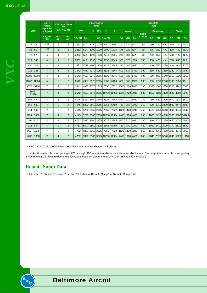
(1) VXC 14, VXC 18, VXC-36 and VXC-45 + Attenuator are shipped in 3 pieces
(2) Intake Attenuator: Access opening is 775 mm high, 405 mm wide and is located at each end of the unit. Discharge Attenuator : Access opening is 405 mm high, 1170 mm wide and is located at blank off side of the unit (VXC14-28 has 650 mm width)
Remote Sump DataRefer to the "Technical Resources" section "Selection of Remote Sump" for Remote Sump Data.
VXC
Unit + Atten.
# piecesshipped
# Access doors (2)
XA, XB, XC
Dimensions(mm)
Weights(kg)
W2 H1 W1 L1 L2 IntakeSolid
Bottom
Discharge Total
XA, XB, XC
Disch.Att.
Int.Att. XA, XB XC XA, XB, XC XA XB XC XA XB XC XA XB XC
14 - 28 4(1) 1 2 2352 N.A. 1090 1030 890 902 110 130 N.A. 30 130 150 N.A. 270 310 N.A.
36 - 65 4(1) 1 2 2352 N.A. 1090 1030 1800 1816 175 220 N.A. 50 175 220 N.A. 400 490 N.A.
72 - 97 4 1 2 2352 N.A. 1090 1030 2710 2731 230 300 N.A. 70 280 350 N.A. 580 720 N.A.
110 - 135 4 1 2 2352 N.A. 1090 1030 3635 3645 300 370 830 100 360 420 N.A. 760 890 N.A.
150 - 205 4 1 2 2583 3728 1600 1420 3635 3645 380 480 1080 120 440 520 1070 940 1120 2270
221 - 265 4 1 2 3542 4687 2070 1955 3525 3645 500 630 1420 190 530 650 1330 1220 1470 2940
S288 - S350 4 1 2 3542 4687 2070 2365 3525 3645 500 630 1420 190 660 800 1640 1350 1620 3250
S403 - S504 4 2 2 3542 4687 2070 2365 5365 5480 660 860 1970 300 830 1090 2240 1790 2250 4510
S576 - S700 7 2 2 3542 4687 2070 2365 7050 7322 1000 1260 2840 380 1320 1600 3280 2700 3240 6500
S806 - S1010 7 4 2 3542 4687 2070 2365 10730 10998 1320 1720 3940 600 1660 2180 4480 3580 4500 9020
357 - 454 4 1 2 4145 5290 2560 2965 3525 3645 560 710 1620 230 710 880 1820 1500 1820 3670
562 - 680 4 2 2 4145 5290 2560 2965 5365 5480 730 980 2240 350 900 1210 2490 1980 2540 5080
714 - 908 7 2 2 4145 5290 2560 2965 7050 7322 1120 1420 3240 460 1420 1760 3640 3000 3640 7340
1124 - 1360 7 4 2 4145 5290 2560 2965 10730 10994 1460 1960 4480 700 1800 2420 4980 3960 5080 10160
495 - 516 4 1 2 4752 5897 2560 3575 3525 3645 560 710 1620 280 810 1030 2130 1650 2020 4030
715 - 804 4 2 2 4752 5897 2560 3575 5365 5480 730 980 2240 420 1020 1410 2920 2170 2810 5580
990 - 1032 7 2 2 4752 5897 2560 3575 7050 7322 1120 1420 3240 560 1620 2060 4260 3300 4040 8060
1430 - 1608 7 4 2 4752 5897 2560 3575 10730 10994 1460 1960 4480 840 2040 2820 5840 4340 5620 11160
Baltimore Aircoil
VXC - E 19
Evaporative C
ondensers
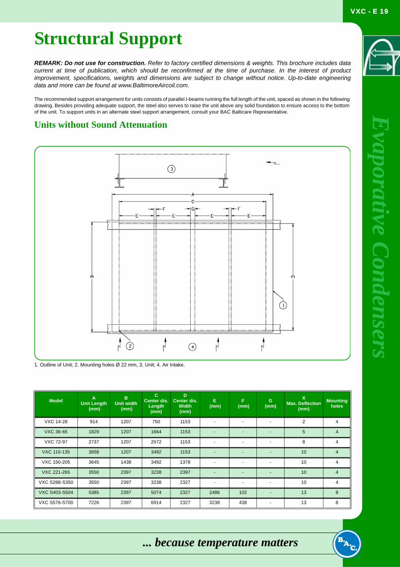
Structural SupportREMARK: Do not use for construction. Refer to factory certified dimensions & weights. This brochure includes datacurrent at time of publication, which should be reconfirmed at the time of purchase. In the interest of productimprovement, specifications, weights and dimensions are subject to change without notice. Up-to-date engineeringdata and more can be found at www.BaltimoreAircoil.com.The recommended support arrangement for units consists of parallel I-beams running the full length of the unit, spaced as shown in the following drawing. Besides providing adequate support, the steel also serves to raise the unit above any solid foundation to ensure access to the bottom of the unit. To support units in an alternate steel support arrangement, consult your BAC Balticare Representative.
Units without Sound Attenuation
Model
AUnit Length
(mm)
BUnit width
(mm)
CCenter dis.
Length(mm)
DCenter dis.
Width(mm)
E (mm)
F (mm)
G(mm)
XMax. Deflection
(mm)Mounting
holes
VXC 14-28 914 1207 750 1153 - - - 2 4
VXC 36-65 1829 1207 1664 1153 - - - 5 4
VXC 72-97 2737 1207 2572 1153 - - - 8 4
VXC 110-135 3658 1207 3492 1153 - - - 10 4
VXC 150-205 3645 1438 3492 1378 - - - 10 4
VXC 221-265 3550 2397 3238 2397 - - - 10 4
VXC S288-S350 3550 2397 3238 2327 - - - 10 4
VXC S403-S504 5385 2397 5074 2327 2486 102 - 13 8
VXC S576-S700 7226 2397 6914 2327 3238 438 - 13 8
1. Outline of Unit; 2. Mounting holes Ø 22 mm, 3. Unit; 4. Air Intake.
... because temperature matters
VXC - E 20
VX
C
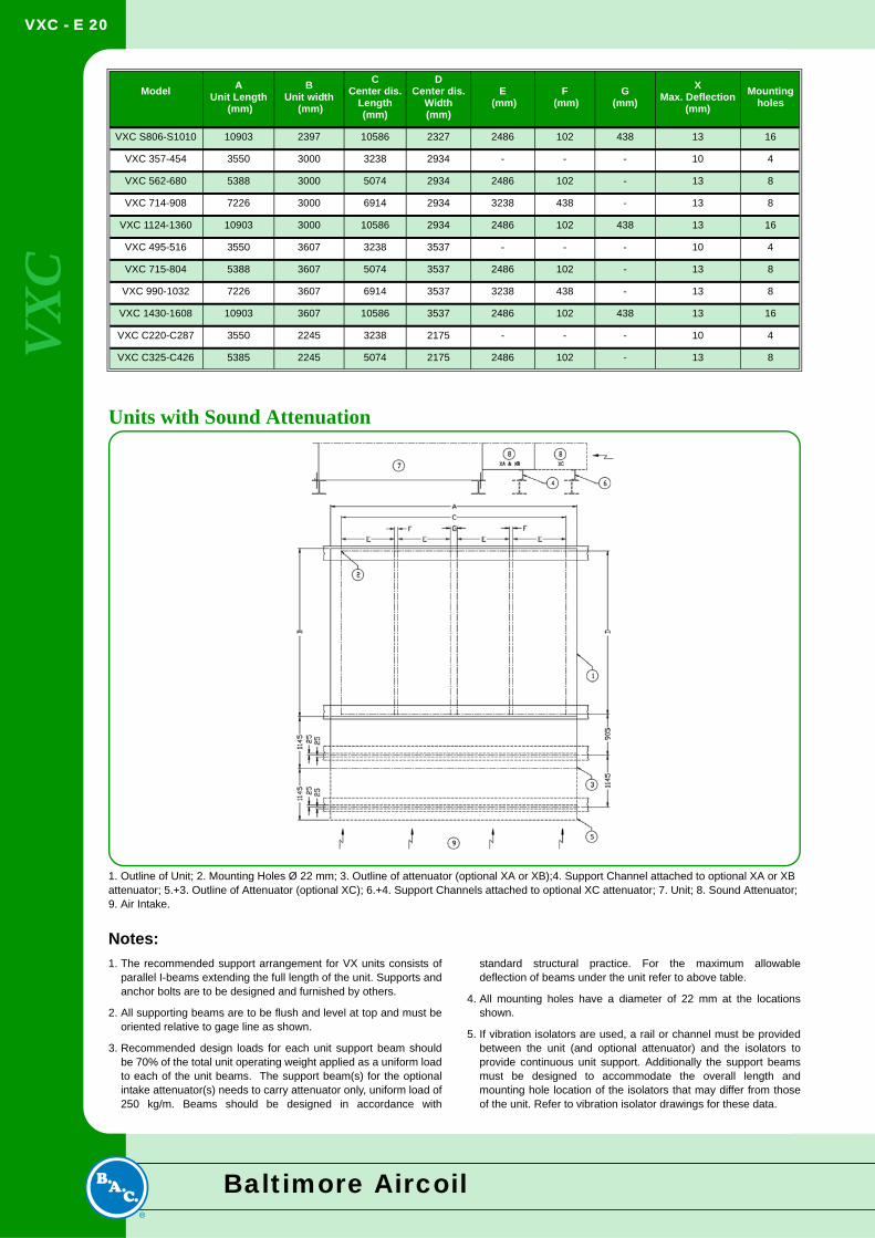
Units with Sound Attenuation
Notes:1. The recommended support arrangement for VX units consists of
parallel I-beams extending the full length of the unit. Supports andanchor bolts are to be designed and furnished by others.
2. All supporting beams are to be flush and level at top and must beoriented relative to gage line as shown.
3. Recommended design loads for each unit support beam shouldbe 70% of the total unit operating weight applied as a uniform loadto each of the unit beams. The support beam(s) for the optionalintake attenuator(s) needs to carry attenuator only, uniform load of250 kg/m. Beams should be designed in accordance with
standard structural practice. For the maximum allowabledeflection of beams under the unit refer to above table.
4. All mounting holes have a diameter of 22 mm at the locationsshown.
5. If vibration isolators are used, a rail or channel must be providedbetween the unit (and optional attenuator) and the isolators toprovide continuous unit support. Additionally the support beamsmust be designed to accommodate the overall length andmounting hole location of the isolators that may differ from thoseof the unit. Refer to vibration isolator drawings for these data.
VXC S806-S1010 10903 2397 10586 2327 2486 102 438 13 16
VXC 357-454 3550 3000 3238 2934 - - - 10 4
VXC 562-680 5388 3000 5074 2934 2486 102 - 13 8
VXC 714-908 7226 3000 6914 2934 3238 438 - 13 8
VXC 1124-1360 10903 3000 10586 2934 2486 102 438 13 16
VXC 495-516 3550 3607 3238 3537 - - - 10 4
VXC 715-804 5388 3607 5074 3537 2486 102 - 13 8
VXC 990-1032 7226 3607 6914 3537 3238 438 - 13 8
VXC 1430-1608 10903 3607 10586 3537 2486 102 438 13 16
VXC C220-C287 3550 2245 3238 2175 - - - 10 4
VXC C325-C426 5385 2245 5074 2175 2486 102 - 13 8
Model
AUnit Length
(mm)
BUnit width
(mm)
CCenter dis.
Length(mm)
DCenter dis.
Width(mm)
E (mm)
F (mm)
G(mm)
XMax. Deflection
(mm)Mounting
holes
1. Outline of Unit; 2. Mounting Holes Ø 22 mm; 3. Outline of attenuator (optional XA or XB);4. Support Channel attached to optional XA or XB attenuator; 5.+3. Outline of Attenuator (optional XC); 6.+4. Support Channels attached to optional XC attenuator; 7. Unit; 8. Sound Attenuator; 9. Air Intake.
Baltimore Aircoil
VXC - E 21
Evaporative C
ondensers
Engineering SpecificationsGeneralA. General: Furnish and install, _____ factory assembled evaporative condenser(s) of counterflow blow-through design, with single side entry, conforming in all aspects to the specifications and schedule as shown on the plans.B. Capacity: The evaporative condenser(s) shall be warranted by the manufacturer to have condensing capacity of _____ kW heat rejection, operating with ____ refrigerant and ___ºC condensing temperature and ___ºC entering wet-bulb temperature.
C. Warranty: The manufacturer’s standard equipment warranty shall be for a period of one year from the date of startup or eighteen months from the date of shipment, whichever ends first.
D. Quality Assurance: The manufacture shall have Management System certified by an accredited registrar as complying with the requirements of ISO-9001:2000 to ensure consistent quality of products and services.
Products1.0 Evaporative Condenser Materials and ComponentsGeneral: All steel panels and structural elements shall be constructed from heavy-gauge, Z600 hot-dip galvanized steel, with cut edges given a protective coating of zinc-rich compound.
2.0 Coil Casing AssemblyThe evaporative condenser shall include a coil casing section consisting of a refrigerant condensing coil, a spray water distribution system, and drift eliminators as indicated by the manufacturer.
1. The refrigerant condensing coil shall be fabricated of all prime surface steel at the manufacturer’s own facility, and hot-dip galvanized after fabrication.a. The refrigerant condensing coil shall be tested at 34 bar air pressure under water.b.The refrigerant condensing coil shall be designed for low pressure drop with sloping tubes for free drainage of liquid refrigerant.c. The refrigerant condensing coil shall be according to European Pressure Equipment Directive 97/23/EC.
2. Water shall be distributed evenly over the coil at a minimum flow
rate sufficient to ensure complete wetting of the coil at all times by large-diameter, non-clog, 360° plastic distribution nozzles spaced across the coil face area in plastic material spray branches. Nozzles shall utilize a two-stage diffusion pattern to provide overlapping, umbrella spray patterns that create multiple intersection points with adjacent nozzles.Spray branches and nozzles shall be held in place by snap-in rubber grommets, allowing quick removal of individual nozzles or complete branches for cleaning or flushing.
3. Removable plastic material drift eliminators shall be positioned to prevent moisture from leaving the evaporative condenser and incorporate a minimum of three (3) changes in air direction.
3.0 Pan AssemblyThe evaporative condenser shall include a pan assembly consisting of cold water basin with pump assembly and fan assemblies with single side air inlet and integral air plenum.
1. The cold water basin shall include: a drain/clean-out connection; a steel strainer; a brass make-up valve; overflow connection; and a water recirculation pump assembly.a. Drain/cleanout connection shall be located in the cold water basin to allow removal of recirculating water.b. Lift-out steel strainer shall be supplied with perforated openings sized smaller than the water distribution nozzle orifices and an integral anti-vortexing hood to prevent air entrainment.c. Brass make-up valve shall be supplied with a large-diameter plastic float arranged for easy adjustment.d. Overflow connection shall be provided in the cold water basin to protect against recirculating water spillage.e. Water recirculation pump shall be a close-coupled, bronze-fitted centrifugal pump equipped with a mechanical seal, mounted on the basin and piped from the suction strainer to the water distribution system.i. The pump shall be installed so that it may drain freely when the basin is drained.ii. The pump assembly shall include an integral metering valve and bleed line to control the bleed rate from the pump discharge to the overflow connection.iii. The pump motor shall be totally enclosed fan cooled (TEFC) type suitable for _____ V, ____ phase______ Hz electrical service.
f. On installations requiring a remote sump, the evaporative condenser shall be modified to accommodate the use of an independent sump and pump for recirculating water (by others)i. The recirculating water pump, steel strainer, make-up valve, and integral bleed line assemblies shall be omitted from the evaporative condenser scope of supply.ii. The evaporative condenser shall be supplied with a cold water basin outlet sized and located as indicated on the drawings for gravity drain to the remote sump.iii. The water distribution system shall have an operating pressure of 14 kPa at the evaporative condenser spray water inlet connection.
2. Air shall enter the evaporative condenser through the centrifugal fan assemblies and integral air plenum.a. Fans and motors shall be located in the dry entering airstream to provide greater reliability and ease of maintenance.b. Fan housings shall have curved inlet rings for efficient air entry and rectangular discharge cowls that extend into the pan to increase fan efficiency and prevent water from entering the fans.c. Fan(s) shall be heavy-duty, centrifugal flow type mounted on a steel shaft with heavy-duty, self-aligning, relubricatable bearings with cast iron housings, designed for a minimum L10 life of 40 000 hours.d. Fan motor(s) shall be totally enclosed fan cooled (TEFC) type, suitable for _____ V, ____ phase, ______ Hz electrical service and shall be mounted on an easily adjusted, heavy-duty motor base. Special moisture protection shall be furnished on the windings, shafts, and bearings.
... because temperature matters
VXC - E 22
VX
C
4.0 Optional Equipment SpecificationsA. Evaporative condenser shall be provided with basin heaters to prevent freezing of the water in the cold water basin when the evaporative condenser is idle.1. The basin heaters shall be selected to maintain +4°C basin water temperature at -18°C ambient temperature.
2. Basin heaters shall be electric immersion type controlled by a remote thermostat with the sensing bulb located in the basin water.
3. Basin heaters shall be provided with a factory-installed low water level cutout switch to prevent heater operation unless the heater elements are fully submerged.
B. Evaporative condenser shall be provided with a factory assembled, field-installed access ladder and handrails to provide access to the top of the evaporative condenser.
C. Evaporative condenser shall be supplied with the Baltiguard Drive System to improve part load efficiency and provide system redundancy in case of a motor failure.1. The Baltiguard® Drive System shall include the main fan motor as listed in the manufacturer’s published literature and a pony motor sized for approximately 1/3 of design kW and 2/3 of design fan speed to optimize energy savings during non-design load conditions.
5.0 Sound5.1 Sound Level: To maintain the quality of the local environment, the maximum sound pressure levels (dB) measured 15 m from the
condenser operating at full fan speed shall not exceed the sound levels detailed below.
Location 63 125 250 500 1000 2000 4000 8000 dB(A)
Discharge
Air Inlet
End
Back
Baltimore Aircoil


