
加速器だから見える世界。
Evolving Mechanical Technology for High Energy Accelerator Science
November 9, 2021
Mechanical Engineering Center(MEC)
Kenji Ueno
1971 Completion of
the first work building
1982~ Mechanical Engineering Center

加速器だから見える世界。
1.History of Mechanical Engineering Center(MEC)2.From the initial support work of Mechanical Engineering Center(MEC)3.Engineering that supports High Energy Accelerator Science
*Belle experiment (SVD, QCS)*TIG automatic welding technology for J-PARC neutrino beamline*CAD, 3D engineering for MLF neutron beamline*To, Fermi Chopper development for MLF neutron beamline*Robot automatic transfer technology for PF beamline*Construction of Cavity Electropolishing(EP) Facility*Cavity Fabrication Facility(CFF) construction *Cavity fabrication technology development*X-band structure manufacturing technology development*Precision measurement without a reference plane
4.Basic research for next-generation of Mechanical Engineering Center(MEC)
5.Summary Reference
Contents

加速器だから見える世界。
Established common research work department, 1st work building completedDepartment Manager Hongo
Manufacture of hydrogen bubble chamber experimental equipmentBending magnet manufacturing, Superconducting electromagnet coil winding jig manufacturingCompletion of radioactive processing building,Manufacturing of septum magnet, manufacturing of Cherenkov counterCompletion of 2nd and 3rd work buildings,Manufacturing of superconducting 2-pole magnets for TRISTANManufacturing of mirror surface shape measuring device for PFAMY Drift Chamber (CDC)for 32,000 Holes (’85) WiringEstablished a work center Head KojimaResearch on ultra-precision machining and diffusion bonding for x-band structure Head KoizumiManufacturing of 14m superconducting 2-pole magnet, Trial production of 30cm X-band structure by interfacial bonding
1971
19731974
1977
1982
1983198419881990
1993
1.History of Mechanical Engineering Center(MEC)(1)
Mission of MECDevelopment, research, design and manufacture of high-energy particle accelerators and devices used for various experiments,And research and development of precision processing technology.
Fiscal year Main events

加速器だから見える世界。
Common Research Facility Work Center Head HitomiDevelopment of brazing technology using a hydrogen furnace,Manufacturing of KEKB measuring instrument SVD-IIManufacturing of X-band 60 cm structure Head UenoRenamed to Mechanical Engineering Center, Applied Research LaboratoryConstruction of cavity electropolishing(EP) facility, ('08) Start of operation of EP facilityConstruction of Cavity Fabrication Facility (CFF)ILC standard cavity production Head YamanakaDevelopment of automatic sample exchange system by robotManufacturing of flux concentrator headHigh-precision form measurement of large objects using a gyro
Head MonjyushiroMuon g-2 / EDM experimental position tracking detector prototype developmentCavity manufacturing for basic experiments Head Hiraki
19972001
200320042007
20112012201420152018
2019
2020
Fiscal year
From the support work to research work
Challenge and creation to the limit: ultra-precision, ultra-low temperature, ultra-high vacuum, high cleanliness, ultra-high speedEquipment requirements: safety, stability (repeatability), ease of operation / operation
1.History of Mechanical Engineering Center(MEC)(2)
Main events

加速器だから見える世界。
Structure welding
Winding work for large coils Experimental equipment parts manufacturing
AMY driftchamber wiring(1985)
2.From the initial support work of the mechanical engineering center
Tig welding
Cherenkov counter manufacturing (1978)
Manufacture of 500MHz superconducting cavity (1981)
Drilling 32,000end plates for AMY
(1984)
加速器だから見える世界。
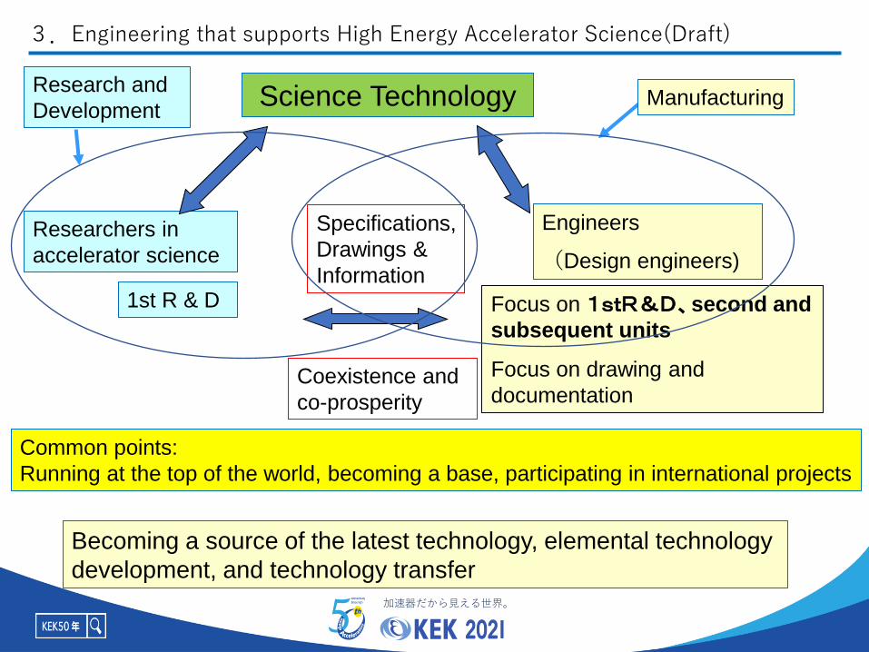
Researchers in
accelerator science
Science Technology
Engineers
(Design engineers)
Specifications,
Drawings &
Information
Coexistence and
co-prosperity
Focus on 1stR&D、second and
subsequent units
Focus on drawing and
documentation
1st R & D
Common points:
Running at the top of the world, becoming a base, participating in international projects
Becoming a source of the latest technology, elemental technology
development, and technology transfer
Research and
Development
3.Engineering that supports High Energy Accelerator Science(Draft)
Manufacturing

加速器だから見える世界。
Collision point measuring device
1m
Aluminum alloy (A5083)Young's modulus 70 GPaCFRP (Dialed + Resin)Young's modulus 240 / 160GPa
Completion of SVD Manufacturing of Ladder Assembly
Support at both ends, deformation
due to own weight:~ 20 μm or less
Ladder deformation: 10 μm or lessBelle detector (about 1000 tons)
Computer calculation diagram
3.1 Belle experiment (Silicon Vertices Detector Development

加速器だから見える世界。
2021/11/9 50周年記念 8
SuperKEKB R&D Magnets for
Nano-beam collision (2010-2013)TRISTAN QCS (1990-1995)
QCS :Quadrupole magnet for Collision in Superconductivity
Courtesy of Ohuchi
Under construction of Super KEKB Nano-beam collision area(2010-2013)
Superconducting magnet near the collision point
SuperKEKB R&D
Magnets (2004-2012)
Length 1.4m QC1P/QC1E prototype magnets
3.2 Belle experiment (QCS Development)(1)

加速器だから見える世界。Machining by CNC
machining center
Tool root check by CAD
Winding work
Fixing work of spacer and
superconducting wireMiniaturized QCS
Joint research with
Cryogenic Science CenterSpacer processing and coil manufacturing
3.2 Belle experiment (QCS Development)(2)
1st R&D quadrupole magnet
6-layer-superconducting quadrupole magnet (2004-2006)
SuperKEKB R&D Magnets for
Nano-beam collision (2010-2013)

加速器だから見える世界。
10
Cryostat being installed
Automatic welding of long shaft pipe (shell)
Weld only from the outside
welding
Pass the welding standards of High Pressure Gas Safety Law
Confirmed the operating performance of the automatic welding machine
(Machine settings, Groove shape, Groove management, Insert ring,
welding current, etc. )
Neutrino Beamline Superconducting
Magnet System
Welding technology transferred to manufacturing
contract company with work procedure manual
By Yasuo Ajima
A shell made by bending a
stainless steel plate with a
thickness of 10 mm
Pressure vessel
holding refrigerant
The pressure vessel
goes inside this tube
Automatic welding machine
Insert ring
Numbers is
the number
of welding
passes3.7m
Weld point
3.3 TIG automatic welding technology for J-PARC neutrino beamline
Joint research with
Cryogenic Science Center

加速器だから見える世界。
11
Large vacuum chamber scattered particle detector
HRC beamline
Design, calculation & installation work study using computer
Strength calculation
of thin AL window
High Resolution Chopper
Spectrometer (HRC)
On 3DCAD,space, weight, interference confirmation,
installation method, maintenance examination of shield High Resolution Chopper Spectrometer (HRC)
4m
Large vacuum chamber
3.4 CAD, 3D engineering for MLF neutron beamline
5m

加速器だから見える世界。
12
Ultra-high-speed, high-precision rotation-controlled chopper
Rotation accuracy:
T0 chopper 6000 rpm Fermi Chopper 36000 rpm
中性子ビー
ムNeutron
pulse
beam
Achievement 600Hz±0.001Hz
Error 0.02 mm at speed 125 m / sec
Neutron
pulse
beam
Error 0.5 mm at speed 94 m / sec
BL12,BL21,BL22,BL23:Total 5sets BL12(HRC):2sets
High Resolution Chopper
Spectrometer (HRC)
Rotor Weight :120kgMaterial : InconelX750
3.5 To, Fermi Chopper development for MLF neutron beamline (1)

加速器だから見える世界。13
t=w/2Rf
w=80mm, w=1mm,
R=300mm, f=100Hz
t=5s: control accuracy
R=300mm
T0 chopper
High speed type (100Hz)BL04, installed in 2008BL12, installed in 2010
Frequency: 100Hz
Required control accuracy: ±5s
Accumulated running time: 4648h > 4000h
Continuous running time: 1551h > 1000h
Motor: AC servo, 10kW, 50Hz, air-cooled
Rotor: Inconel X750, 120kg, 4.7kgm2,
L=300mm, in vacuum (~1Pa)
Bearings: water-cooled ball bearings
1
0
nu
mb
er
of
ev
en
ts
-5 0 5
deviation from target timing (s)
ON OFF
Phase control circuit
1s
off-beam
experiment
High Resolution Chopper
Spectrometer (HRC)
Semi-auto installation mechanism
for air & water
Semi-automatic installation guide
Electrical system
Realization of stable operation for a long time> 4000h
3.5 To, Fermi Chopper development for MLF neutron beamline (2)

加速器だから見える世界。14
Slit
Mag. bearingControl circuit
Motor
Rotor pulse
ACC
Mag. bearing
Motor
Rotor pulse
DDSf=0.012Hzfmax=600Hz
202.5
202.0
201.5
201.0
200.5
frequ
enc
y (H
z)
1.0841.0821.080
voltage (V)f=1Hz
ACCf = 1/tf = |df/dt| t = f2t
t = 0.7s x 0.3 = 0.2s
f = 0.2Hz (f=1kHz)= 0.07Hz (f=600Hz)
Analog input 0-5V:100-600Hz
Development of Fermi chopper controller
Digital inputDirect Digital Synthesis
n=120f/p
n:Number of speed(rpm)
p:Number of pole
f : Frequency of E. power
Improvement of turbo molecular pump(TMP)
TMP
Fermi chopper
TMPcontroller
TMPcontroller
Control circuit
Slit
High Resolution Chopper
Spectrometer (HRC)
3.5 To, Fermi Chopper development for MLF neutron beamline (3)

加速器だから見える世界。
15
Force Sensor 4-axis Robot
Goniometer head
96x3=288pins
Calibration
Detection of collisions
Cryo Tongs=Robot hands
2D barcode reader
PAM : PF Automated Mounter
Application to complex movements of industrial robots PAM BL-5A
3.6 Robot automatic transfer technology for PF beamline
Liquid N2 Dewar
Cassette of
cryo-pins

加速器だから見える世界。
EP HPR Assembly
In Clean room
(Class 10)
Flange-CP
Baking
(Class 1000)Hanging
StandVertical Test
Inspection of
Inner Surface
Rinsing
H2O2
Hot bath
(Alcohol)
(Degreasing)
Pre-tuning
of adjustment
Courtesy of STF Cavity G
Mechanical Engineering
Center Responsible Part
Vacuum furnace heat
treatment (Off line)
Cavities manufacuterd at KEK: KEKB, Club, ERL, ILC, Single cavity
Cavity production and cavity electropolishing in KEK Tsukuba campus
3.7 Construction of Cavity Electropolishing(EP) Facility (1)

加速器だから見える世界。EP liquid reserve tank installed on
the ground floor
EP acid: 1200ℓ
For ILC specialization, 9-cell
cavity, single-cell cavity
Amount of polishing per cell when polishing 20 μm
First EP processing resultーー--- A value of 27.3 MV / m in the
electric field was obtained.
EP equipment layout
Stable electrolytic polishing process and assembly
work in a clean room
Clean room(Class 10)
EP area Exhaust gas treatment equipment
Conceptual drawing when working on the electrolytic polishing bed
Joint work with
Chemical Center3.7 Construction of Cavity Electropolishing(EP) Facility (2)

加速器だから見える世界。 18
Superconducting cavity
manufacturing process
Condition: 18,000 / 5 years
6,000 / Asia area
Goal: 6 bottles / day
Maintaining vacuum, strength, high electric field
performance, and passing high pressure gas regulations
Total length 1247.6 mm
Large diameter φ206.85 mm
Courtesy of Kako
1.3GHz, L band
Establishment of electron beam welding (EBW) technology
3.8 Cavity Fabrication Facility (CFF) construction (1)

加速器だから見える世界。
Clean room 19m x 14m, 5m Height
Cleanliness ISO 5
Grand opening ceremony July 13, 2011Completed clean room
Press processServo press machineEBW machine
Aiming to be a base for ILC cavity production
3.8 Cavity Fabrication Facility (CFF) construction (2)Joint work with
Accelerator Groupe

加速器だから見える世界。
EBW processing
Example of temperature
calculation during EBW ANSYS
Completed (Before wearing the jacket)
Old model EBW
After this process →EP processing,……
0mm
0.5mm
Nb
Material
Ti
Welding joint
1mmEBW power 0.9kw,
Beam dia. 3mm,
Moving speed 5mm/sec,
Giving heat on the Ti / Nb
surface and simulated the
temperature distribution. (Plot
after welding length of 20mm)EBW of equator area
1.5mm
offset
Nb Ti
Offset1.5mm
Beam center
Temperature calculation by Shigeaki Koike
Speed 2.5mm/sec
Temperature distribution
New model EBW
3.8 Cavity Fabrication Facility (CFF) construction (3)

加速器だから見える世界。X band 60cm structure 11.424GHZ
High precision machining technology and disc diffusion bonding
Contour degree in the air fuselage ± 1 μm or less
Flatness of 0.5 μm or less
Surface roughness 0.05 μm Rz or less
Material: Oxygen-free copper (99.996%)
Use of vacuum chuck
and diamond tool
Heatherington Hydrogen
Atmospheric Furnace
Main dimensions
Joint surface inspection after diffusion bonding
Deformation after diffusion bonding<0.01%
3.9 X-band structure manufacturing technology development(1)

加速器だから見える世界。
Development of in-line outer diameter measuring instrument
Capacitive sensor
Reference disk
Measurement disc
Capacitive displacement sensors fixed at regular intervals are
moved and compared with a standard dimensional disc.
Repeated measurement accuracy is ± 0.2 μm
0
20
40
60
80
100
120
140
160
-1.4
-1.3
-1.2
-1.1 -1
-0.9
-0.8
-0.7
-0.6
-0.5
-0.4
-0.3
-0.2
-0.1 0
0.1
0.2
0.3
0.4
0.5
0.6
0.7
0.8
0.9 1
1.1
1.2
1.3
1.4
1.5
1.6
1.7
erorr (μm)
ディ
スク
枚数
σ:0.35μm3σ:1.05μm
0
1
2
3
4
5
6
7
8
-1.5 -1 -0.5 0 0.5 1 1.5
Frequency deviation (MHz)
Popula
tion
Deviation from the design value:±0.001mm
12.93±0.110.9297±0.002
φ2a
φ2b
φc
φ61±
0.0
02
X-band structure manufacturing technology application
Design and manufacture
of S-band RF gun
22 units have been
manufactured
Error(μm)
Frequency deviation(MHz)
3.9 X-band structure manufacturing technology development(2)
#of cells
#of cells

加速器だから見える世界。
Unlike the
interferometry, it is
possible to measure
the shape of 5 nm
without using a
reference plane.
Measure the tilt angle of a surface with a laser
It is possible to measure shape mirrors that cannot be measured with conventional
interferometers.
Measurement of EUV mirror, etc.
Measuring principle Measuring equipment
1m diameter mirror Parabolic mirror Spherical mirror
3.10 Precision measurement without a reference plane

加速器だから見える世界。
Actively engage in development work while making the best use of excellent
facilities, machine tools and using computer power.
Flux concentrator head
Precision mechanization,high precision,
high performance
Cavity manufacturing technology base with CFF as the corePrecision measuring device that applies precision/newly processing technology
New measurement method using gyro
Position tracking detector of J-PARC Muon g-2/EDM experiment
Crystal goniometer device
Mechanical engineering evolving with the evolution of accelerator science
Specific future research themesRecent research results
4. Basic research for next-generation of the mechanical engineering center
Recent research results

加速器だから見える世界。
• Big projects related to accelerator science are carried out once every 20 or 30 years.
• Therefore, it is an important responsibility for MEC to work the pilot activities of the project.
• I would like to end my report with the hope of further development of personal connections and human resources.
• I hope for the further development of KEK.
5. Summary

加速器だから見える世界。
1. KEK Applied Research Laboratory : 50 years of history 2021.3
2. KEK : Mechanical Engineering Center Activity Report 2004-2006,KEK Report 2008-4,June 2008 A/H
3. KEK : Mechanical Engineering Center Activity Report 2010-2016,KEK Progress Report 2017-11,February 2018 A
4. MEC Handbook Editorial Committee : Mechanical Engineering Center Handbook, 2002.3
5. Kume Tatsuya : Introducing KEK and Mechanical Engineering Center, 2008.12
These references are written in Japanese
Reference


