International Journal of Applied Research in Mechanical Engineering (IJARME) ISSN: 2231 –5950, Volume-2, Issue-1, 2012
81
Experimental and Parametric Study of Extended Fins In The
Optimization of Internal Combustion Engine Cooling Using CFD
J.Ajay Paul,Sagar Chavan Vijay, U.Magarajan & R.Thundil Karuppa Raj
VIT UNIVERSITY, VELLORE, TAMILNADU,INDIA E-mail : [email protected]
Abstract - In this experiment the single cylinder air cooled engines was assumed to be a set of annular fins mounted on a cylinder. Numerical simulations were carried out to determine the heat transfer characteristics of different fin parameters namely, number of fins, fin thickness at varying air velocities. A cylinder with a single fin mounted on it was tested experimentally. The numerical simulation of the same setup was done using CFD. The results validated with close accuracy with the experimental results. Cylinders with fins of 4 mm and 6 mm thickness were simulated for 1, 3, 4 &6 fin configurations. Keywords-Numerical simulation,.Annular fins.
I. INTRODUCTION
As the fossil fuel reserves are depleting day by day, the spiraling fuel price is pushing the technology towards it limit to provide engines which are highly efficient and produces high specific power. Air cooled engines are gradually phased out and are being replaced by water cooled engines which are far more efficient in dissipating heat, but in cases of two wheelers and certain other applications, air cooled engines are the only viable option due to space constraints.
The heat which is generated during combustion in an internal combustion engine should be maintained at the highest level possible to increase its thermal efficiency, but in order to prevent the thermal damage to the engine components and the lubricants some amount of heat must be removed from the system. If the cooling is not sufficient greater thermal expansion of the engine might occur and scuffing might occur between the pistons. Parameter analyzed in this paper includes fin number, fin thickness and wind velocities. The meshing for the computational problem was done primarily using the software ICEM CFD and the solver used was FLUENT.Hexa-meshing was used for all geometries. The numerical study is extended to study the effect of fin pitch, normal and tapered fins, effect of holes and slits in fins etc.
II. EXPERIMENTAL SET UP
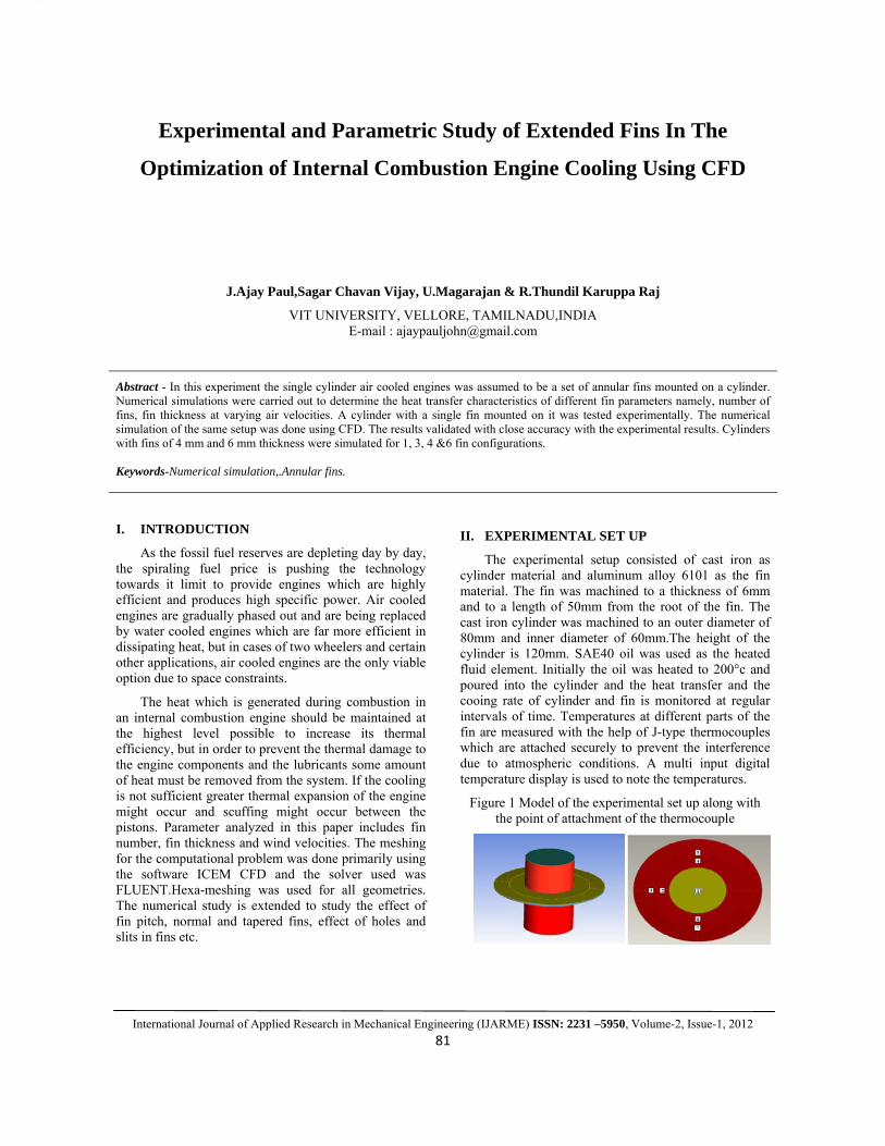
The experimental setup consisted of cast iron as cylinder material and aluminum alloy 6101 as the fin material. The fin was machined to a thickness of 6mm and to a length of 50mm from the root of the fin. The cast iron cylinder was machined to an outer diameter of 80mm and inner diameter of 60mm.The height of the cylinder is 120mm. SAE40 oil was used as the heated fluid element. Initially the oil was heated to 200°c and poured into the cylinder and the heat transfer and the cooing rate of cylinder and fin is monitored at regular intervals of time. Temperatures at different parts of the fin are measured with the help of J-type thermocouples which are attached securely to prevent the interference due to atmospheric conditions. A multi input digital temperature display is used to note the temperatures.
Figure 1 Model of the experimental set up along with the point of attachment of the thermocouple
Experimental and Parametric Study of Extended Fins In The Optimization of Internal Combustion Engine Cooling Using CFD
International Journal of Applied Research in Mechanical Engineering (IJARME) ISSN: 2231 –5950, Volume-2, Issue-1, 2012
82
The volume of the hollow portion of the experimental cylinder is 300cm . A heater with electrical power of 400 W and J type thermocouple were inserted into the cylinder to identify the temperature. The heat storage liquid was heated to approximately 200°C and is poured into the cylinder and the cap is placed above the cylinder. The temperature of the heat storage liquid was decreased to 120 °C by cooling at room temperature. The heat release from the cylinder was obtained by multiplying the heat capacity of the heat storage liquid by the difference between 120 °C and the temperature after every 30 seconds at an air velocity of 0 km/hr. The experiments were carried out at an ambient temperature of 33°C .The ambient temperature has a significant effect on the heat release from the cylinder. The experimental setup is shown in the image below.
Figure.2 Experimental setup
COMPUTATIONAL MODELING
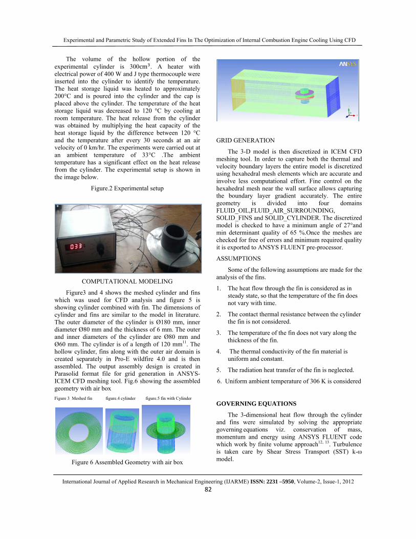
Figure3 and 4 shows the meshed cylinder and fins which was used for CFD analysis and figure 5 is showing cylinder combined with fin. The dimensions of cylinder and fins are similar to the model in literature. The outer diameter of the cylinder is Ø180 mm, inner diameter Ø80 mm and the thickness of 6 mm. The outer and inner diameters of the cylinder are Ø80 mm and Ø60 mm. The cylinder is of a length of 120 mm11. The hollow cylinder, fins along with the outer air domain is created separately in Pro-E wildfire 4.0 and is then assembled. The output assembly design is created in Parasolid format file for grid generation in ANSYS-ICEM CFD meshing tool. Fig.6 showing the assembled geometry with air box Figure 3 Meshed fin figure.4 cylinder figure.5 fin with Cylinder
Figure 6 Assembled Geometry with air box
GRID GENERATION
The 3-D model is then discretized in ICEM CFD meshing tool. In order to capture both the thermal and velocity boundary layers the entire model is discretized using hexahedral mesh elements which are accurate and involve less computational effort. Fine control on the hexahedral mesh near the wall surface allows capturing the boundary layer gradient accurately. The entire geometry is divided into four domains FLUID_OIL,FLUID_AIR_SURROUNDING, SOLID_FINS and SOLID_CYLINDER. The discretized model is checked to have a minimum angle of 27°and min determinant quality of 65 %.Once the meshes are checked for free of errors and minimum required quality it is exported to ANSYS FLUENT pre-processor.
ASSUMPTIONS
Some of the following assumptions are made for the analysis of the fins.
1. The heat flow through the fin is considered as in steady state, so that the temperature of the fin does not vary with time.
2. The contact thermal resistance between the cylinder the fin is not considered.
3. The temperature of the fin does not vary along the thickness of the fin.
4. The thermal conductivity of the fin material is uniform and constant.
5. The radiation heat transfer of the fin is neglected.
6. Uniform ambient temperature of 306 K is considered
GOVERNING EQUATIONS
The 3-dimensional heat flow through the cylinder and fins were simulated by solving the appropriate governing equations viz. conservation of mass, momentum and energy using ANSYS FLUENT code which work by finite volume approach12, 13. Turbulence is taken care by Shear Stress Transport (SST) k-ω model.
Experimental and Parametric Study of Extended Fins In The Optimization of Internal Combustion Engine Cooling Using CFD
International Journal of Applied Research in Mechanical Engineering (IJARME) ISSN: 2231 –5950, Volume-2, Issue-1, 2012
83
Conservation of mass: 0Vρ . =⎟⎟⎠
⎞⎜⎜⎝
⎛∇
→ ------------------ (4)
X-momentum: zτ
yτ
xτ
xp- Vρu . zxyxxx
∂∂
+∂
∂+
∂∂
+∂∂
=⎟⎠⎞
⎜⎝⎛∇
→ ------ (5.1)
Y-momentum: ρgzτ
yτ
xτ
yp- Vρu . zyyyxy +
∂
∂+
∂
∂+
∂
∂+
∂∂
=⎟⎠⎞⎜
⎝⎛∇
→
---- (5.2)
Z-momentum: ρgzτ
yτ
xτ
zp- Vρu . zzyzxz +
∂∂
+∂
∂+
∂∂
+∂∂
=⎟⎠⎞
⎜⎝⎛∇
→ -
--- (5.3)
Energy: ( ) φqTk.v.p- Vρe . ++∇∇+∇=⎟⎠⎞
⎜⎝⎛∇
→→ ------------ (6)
SST omega turbulence equation: ( ) ( )
kkkj
kji
i SYGxkΓ
xxρku
tρk
+−+⎥⎥⎦
⎤
⎢⎢⎣
⎡
∂∂
∂∂
=∂
∂+
∂∂ ------------ (7)
BOUNDARY CONDITION SETUP
Both the fluids SAE 40 oil and air are assumed to be incompressible fluids. Ambient temperature and pressure are assumed as 306 K and 101325 Pa respectively. The values of the boundary conditions like operating temperature, velocity of air are taken from the experimental work. Other boundary conditions like density, specific heat, thermal conductivity and other material properties are considered as constants throughout the analysis. The mesh is imported to ANSYS-FLUENT and then the domains are initialized.
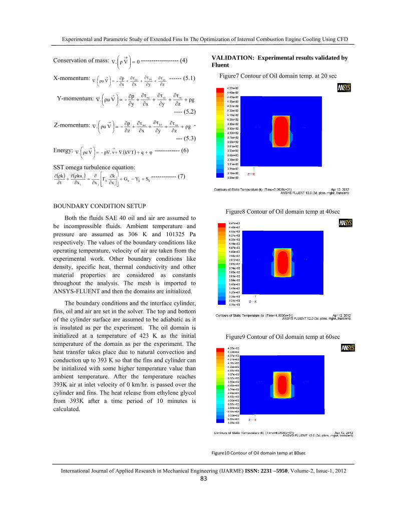
The boundary conditions and the interface cylinder, fins, oil and air are set in the solver. The top and bottom of the cylinder surface are assumed to be adiabatic as it is insulated as per the experiment. The oil domain is initialized at a temperature of 423 K as the initial temperature of the domain as per the experiment. The heat transfer takes place due to natural convection and conduction up to 393 K so that the fins and cylinder can be initialized with some higher temperature value than ambient temperature. After the temperature reaches 393K air at inlet velocity of 0 km/hr. is passed over the cylinder and fins. The heat release from ethylene glycol from 393K after a time period of 10 minutes is calculated.
VALIDATION: Experimental results validated by Fluent
Figure7 Contour of Oil domain temp. at 20 sec
Figure8 Contour of Oil domain temp at 40sec
Figure9 Contour of Oil domain temp at 60sec
Figure10 Contour of Oil domain temp at 80sec
Experimental and Parametric Study of Extended Fins In The Optimization of Internal Combustion Engine Cooling Using CFD
International Journal of Applied Research in Mechanical Engineering (IJARME) ISSN: 2231 –5950, Volume-2, Issue-1, 2012
84
Figure10 Contour of Oil domain temp at 80sec
Figure11 Contour of oil domain temp at 100sec
Figure12 Temperature difference at fin root
Figure13Temperature difference at 12mm from root of fin
Figure14Temperature difference at 24mm from root of fin
From figures 12, 13&14, the CFD values obtained correspond to the value obtained by the experiments with a maximum error of +- 10%.
RESULTS AND DISCUSSIONS
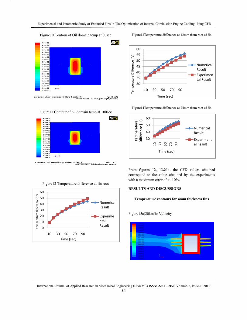
Temperature contours for 4mm thickness fins
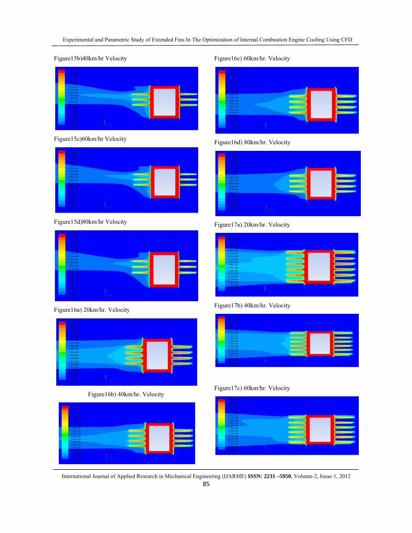
Figure15a)20km/hr Velocity
0
10
20
30
40
50
60
10 30 50 70 90
Tempe
rature Differen
ce (°c)
Time (sec)
Numerical Result
Experimental Result
30
35
40
45
50
55
60
10 30 50 70 90
Tempe
rature Differen
ce (°c)
Time (sec)
Numerical ResultExperimental Result
30
40
50
60
10 30 50 70 90
Tempe
rature
Differen
ce (
c)
Time (sec)
Numerical Result
Experimental Result
Experimental and Parametric Study of Extended Fins In The Optimization of Internal Combustion Engine Cooling Using CFD
International Journal of Applied Research in Mechanical Engineering (IJARME) ISSN: 2231 –5950, Volume-2, Issue-1, 2012
85
Figure15b)40km/hr Velocity
Figure15c)60km/hr Velocity
Figure15d)80km/hr Velocity
Figure16a) 20km/hr. Velocity
Figure16b) 40km/hr. Velocity
Figure16c) 60km/hr. Velocity
Figure16d) 80km/hr. Velocity
Figure17a) 20km/hr. Velocity
Figure17b) 40km/hr. Velocity
Figure17c) 60km/hr. Velocity
Experimental and Parametric Study of Extended Fins In The Optimization of Internal Combustion Engine Cooling Using CFD
International Journal of Applied Research in Mechanical Engineering (IJARME) ISSN: 2231 –5950, Volume-2, Issue-1, 2012
86
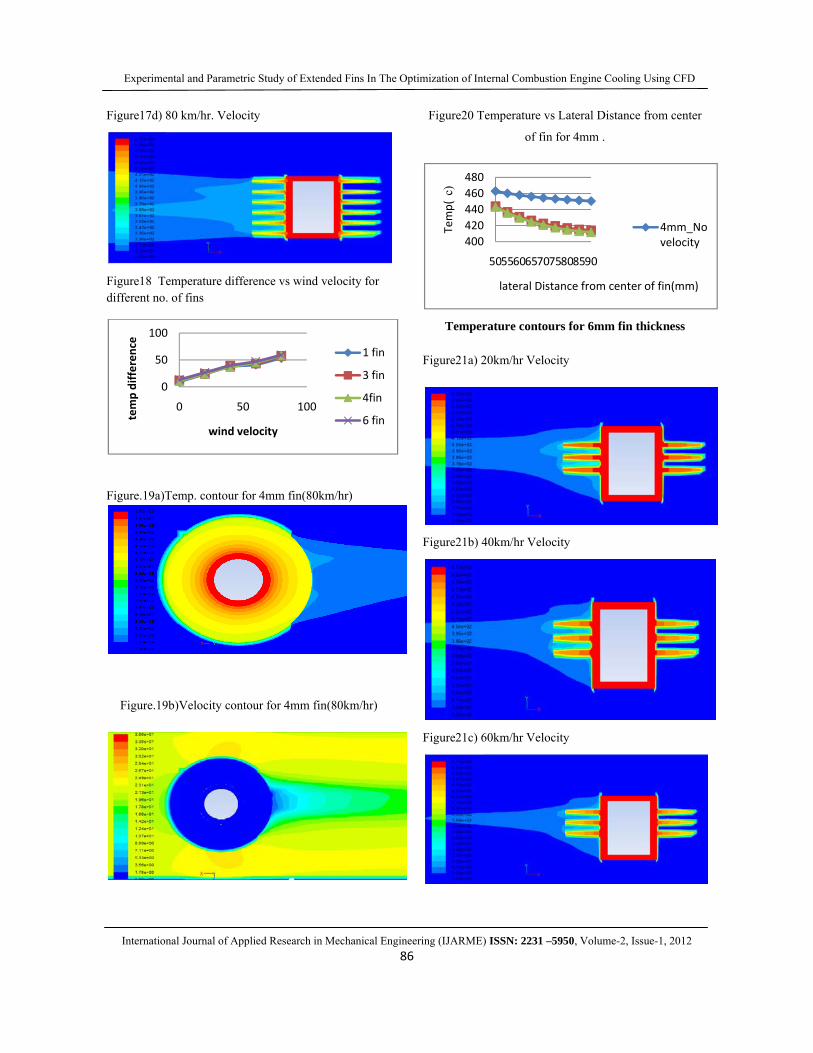
Figure17d) 80 km/hr. Velocity
Figure18 Temperature difference vs wind velocity for different no. of fins
Figure.19a)Temp. contour for 4mm fin(80km/hr)
Figure.19b)Velocity contour for 4mm fin(80km/hr)
Figure20 Temperature vs Lateral Distance from center
of fin for 4mm .
Temperature contours for 6mm fin thickness
Figure21a) 20km/hr Velocity
Figure21b) 40km/hr Velocity
Figure21c) 60km/hr Velocity
0
50
100
0 50 100
temp differen
ce
wind velocity
1 fin
3 fin
4fin
6 fin
400420440460480
505560657075808590
Temp(
c)
lateral Distance from center of fin(mm)
4mm_No velocity
Experimental and Parametric Study of Extended Fins In The Optimization of Internal Combustion Engine Cooling Using CFD
International Journal of Applied Research in Mechanical Engineering (IJARME) ISSN: 2231 –5950, Volume-2, Issue-1, 2012
87
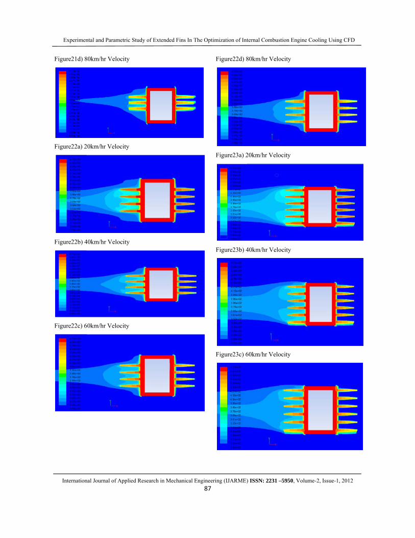
Figure21d) 80km/hr Velocity
Figure22a) 20km/hr Velocity
Figure22b) 40km/hr Velocity
Figure22c) 60km/hr Velocity
Figure22d) 80km/hr Velocity
Figure23a) 20km/hr Velocity
Figure23b) 40km/hr Velocity
Figure23c) 60km/hr Velocity
Experimenta
International
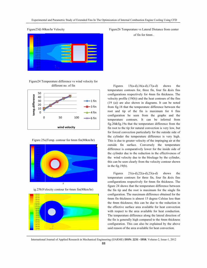
Figure23d) 80
Figure24 Tem
Figure.25a
ig.25b)Ve
01020304050
0
temp.differen
ce
al and Parametri
l Journal of App
km/hr Velocity
mperature diffedifferent n
a)Temp. contou
F
elocity contour
50
wind
ic Study of Exten
plied Research in
y
erence vs windno. of fin
ur for 6mm fin
F
r for 6mm fin(8
100
d velocity
nded Fins In The
n Mechanical En
d velocity for
n(80km/hr)
80km/hr)
1 fin
3 fin
4 fin
6 fin
e Optimization o
ngineering (IJAR88
Figure2
Figutemperatconfigurvelocity (19 (a)) from figroot anconfigurtemperatfig.20&ffin root for forcethe cylinThis is doutside differencthe cylinthe winthis can in the fig
Figutemperatconfigurfigure 24the fin tconfigur6mm finthe 4mmthe effecwith resThe temthe fin isconfigursaid reas
of Internal Comb
RME) ISSN: 223
26 Temperatur
of
ures 15(a-dture contours rations respectprofile (19(b)are also show
g.18 that the tend tip of theration be seeture contoursfig.19a that theto the tip for ned convection pnder the temp
due to greater vfin surface.
ce is comparatnder due to thend velocity duebe seen clearly
g.19(b).
ures 21(a-dture contours rations respect4 shows that thtip and the rooration. The maxn thickness is am thickness; thctive surface aspect to the ar
mperature differs generally higration. This cason of the area
bustion Engine C
31 –5950, Volum
re vs Lateral Di
f fin for 6mm .
d),16(a-d),17(a-for, three fin,ively for 4mm) and the heat wn in diagramemperature diffe fin is maxen from thes. It can be temperature
natural convectparticularly forperature differvelocity of the . Converselytively lower foe reduction in e to the blockay from the velo
d),22(a-d),23(a-for three fin, ively for 6mmhe temperatureot is maximumximum differealmost 15 degrhis can be duearea available rea available frence along thegh compared toan also be expl
available for h
Cooling Using C
me-2, Issue-1, 20
istance from ce
-d) shows , four fin &six
m fin thicknesscontours of th
ms. It can be ference betweeximum for 6e graphs andbe inferred difference from
tion is very lowr the outside srence is very impinging air
y the temperor the inside sithe effectiveneage by the cylocity contour s
-d) shows four fin &six
m fin thicknesse difference betm for the singnce obtained f
ree Celsius less to the reductifor heat conve
for heat condue lateral directio the 4mm thiclained by the aheat convection
CFD
012
enter
the x fins s. The he fins
noted en the
6 fins d the
from m the w, but ide of high. at the rature ide of ess of inder,
shown
the x fins s. The tween
gle fin for the s than ion in ection
uction. ion of
ckness above n.

Experimental and Parametric Study of Extended Fins In The Optimization of Internal Combustion Engine Cooling Using CFD
International Journal of Applied Research in Mechanical Engineering (IJARME) ISSN: 2231 –5950, Volume-2, Issue-1, 2012
89
Figure.27 Heat transfer vs. air velocity for 6mm and 4mm thickness 1 no. of fin
Figure.28 Heat transfer vs. air velocity for 6mm and
4mm thickness 3 no. of fin
Figure.29 Heat transfer vs. air velocity for 6mm and 4mm thickness 4 no. of fin.
Figure.30 Heat transfer vs. air velocity for 6mm and 4mm thickness 6 no. of fin
For figure 27-30, it shows the variation of the heat transfer with respect to velocity. The heat transfer was calculated directly from the fluent software. At zero velocity it is seen that the heat transfer from the 4mm
and 6mm fins are the same. When the velocity is increased it can be seen that the heat transfer is increased with due to forced convection and also due to the swirl generated between two fins which induces turbulences and hence higher heat transfer. For a larger fin thickness, the corresponding fin spacing is comparatively small. As a consequence, the generated swirled flow may mingle with the main flow and result in a higher heat transfer performance.
CONCLUSION
1. The difference of heat transfer between 4mm fins and 6mm fins are negligible same at zero velocity. So for stationary engines, fins of 4mm can be used with little difference in heat transfer, but helps in reducing the cost.
2. The heat transfer from 6mm fins is found to be the higher at high velocities. For high speed vehicles thicker fins provide better efficiency.
3. When fin thickness was increased, the reduced gap between the fins resulted in swirls being created which helped in increasing the heat transfer.
4. Large number of fins with less thickness can be preferred in high speed vehicles than thick fins with less numbers as it helps inducing greater turbulence and hence higher heat transfer.
5. The heat transfer from the outside portion of the fin is found to be less. This is our future scope of our study, as we try to increase its convection by providing slits and holes.
REFERENCES [1] Masao Yoshida, M., Ishihara, S., Nakashima, K.
and Yamamoto.M., Optimum Fin Layout of Air-Cooled Engine Cylinder in Air Stream Development of Air-Cooled Cylinder Utilizing Natural Convection, SAE Paper No. 2005-01-1385, (2005)
[2] Gibson, A.H., the Air Cooling of Petrol Engines, Proceedings of the Institute of Automobile Engineers, Vol. XIV (pp. 243-275, 1920)
[3] Biermann, A. E. and Pinkel, B., Heat Transfer from Finned Metal Cylinders in an Air Stream, NACA Report No. 488, (1935)
[4] Thornhill, D. and May, A., an Experimental Investigation into the Cooling of Finned Metal Cylinders, in a Free Air Stream, SAE Paper No.1999-01-3307, (1999)
[5] Thornhill, D., Graham, A., Cunnigham, G., Troxier, P. and Meyer, R., Experimental
0200400600
0 50 100
Heat T
ransfer(W)
Wind velocity(km/hr)
6mm thickness 1 fin
4mm thickness 1 fin
0
1000
2000
0 50 100
Heat
Tram
sfer(W
)
Air velocity(km/hr)
6mm thickness 3 fin
4mm thickness 3 fin
0
500
1000
1500
2000
2500
0 20 40 60 80 100
Heat T
ransfer(W)
Air velocity(km/hr)
6mm thickness 4 fin4mm thickness 4 fin
020004000
0 50 100
Heat
tran
sfer(W
)
Air velocity(km/hr)
6mm thickness 6 fins
4mm thickness 6 fins
Experimental and Parametric Study of Extended Fins In The Optimization of Internal Combustion Engine Cooling Using CFD
International Journal of Applied Research in Mechanical Engineering (IJARME) ISSN: 2231 –5950, Volume-2, Issue-1, 2012
90
Investigation into the Free Air-Cooling of Air-Cooled Cylinders, SAE, Paper No. 2003-32-0034, (2003)
[6] Schey, O. W. and Biermann, A. E., Heat Dissipation from a Finned Cylinder at Different Fin-Plane / Air-Stream Angles, NACA, Technical Notes No. 429, (1932)
[7] Schey, O. W. and Rollin, V. G., The Effect of Baffles on the Temperature Distribution and Heat-Transfer Coefficients of Finned Cylinders, NACA, Report No. 511, (1936)
[8] Biermann, A. E., Heat Transfer from Cylinders Having Closely Spaced Fins, NACA, Technical Notes No. 602, (1937)
[9] Brevoort, M. J. and Rollin, V.G., Air Flow around Finned Cylinders, NACA Report No.555, (1937)
[10] Ellerbrock, H. H. and Biermann, A. E., Surface Heat- Transfer Coefficients of Finned Cylinders, NACA, Report No. 676, (1939)
[11] Yoshida, M., Ishihara, S., Nakashima, K. and Yamamoto, M., Development of Air-Cooled Cylinder by Utilizing Natural Convection, SAE Paper No.2005-01-1385, (2005) by
[12] Pathak sunil, Turbo charging and oil techniques in light motor vehicles, Res.J.recent sci, 1(1), 60-65 (2012.


