i
EXPERIMENTAL EVALUATION OF THE EFFECT OF MINIMAL QUANTITY
LUBRICATION WITH DIFFERENT CUTTING FLUIDS IN DRILLING AISI 4340 STEEL
By
Md. Isanul Haque A Thesis
Submitted to the Department of Industrial & Production Engineering
in Partial Fulfilment of the requirements for the Degree
of MASTER IN INDUSTRIAL & PRODUCTION ENGINEERING
DEPARTMENT OF INDUSTRIAL & PRODUCTION ENGINEERING BANGLADESH UNIVERSITY OF ENGINEERING & TECHNOLOGY
DHAKA, BANGLADESH
December 2014
ii
The thesis titled Experimental Evaluation of the Effect of Minimal Quantity
Lubrication with Different Cutting Fluids in Drilling AISI 4340 Steel submitted by
Md. Isanul Haque, Student No. 0409082004 P, Session- April 2009, has been accepted as
satisfactory in partial fulfillment of the requirement for the degree of Master in Industrial
and Production Engineering on December 20, 2014.
BOARD OF EXAMINERS
1. Dr. Nikhil Ranjan Dhar Chairman Professor
Department of Industrial & Production Engineering BUET, Dhaka
(Supervisor)
2. Dr. Ferdous Sarwar Member Assistant Professor
Department of Industrial & Production Engineering BUET, Dhaka.
3. Dr. Shuva Ghosh Member Assistant Professor
Department of Industrial & Production Engineering BUET, Dhaka.

iii
DECLARATION
It is hereby declared that this thesis or any part of it has not been submitted elsewhere for
the award of any degree or diploma.
Md. Isanul Haque

iv
This work is dedicated
to my loving
Father
&
Mother

v
CONTENTS
Acknowledgement............................................................................................... vi
Abstract................................................................................................................ vii
List of Figures...................................................................................................... viii
List of Tables………………………………………………………………….. ix
Chapter 1 Introduction……………………………………………………… 1 1.1 Literature Review 3 1.1.1 Machinining with Conventional Twist drill………………….. 21 1.1.2 Machinining with Conventional Cutting Fluid………………. 23 1.1.3 Vegetable Oil based Cutting Fluid…………………………… 26 1.1.4 Drilling under Dry and MQL Condition…............................... 28 1.1.5 Summary of the Review........................................................... 29 1.2 Objectives of the Present work.......…………….…........................... 30
Chapter 2 Experimental Investigations……………………………………. 31
2.1 Experimental Procedure and Conditions …………………………... 31 2.2 Experimental Results ………………………………………………. 34 2.2.1 Number of hole……………………………………………… 34 2.2.2 Chip Formation …………………..………………………….. 35 2.2.3 Roundness deviation………………………………………… 35 2.2.4 Dimensional Deviation or Taper….…………………………. 37 2.2.5 Surface Roughness …...……………………………………… 38 2.2.6 Tool Wear …………………………………………………… 39
Chapter 3 Discussion on Experimental Results…………………………… 40
3.1 Number of hole……………………………………………………. 40 3.2 Chip Formation …………………..………………………………... 40 3.3 Roundness deviation……………………………………………….. 41 3.4 Dimensional Deviation or Taper….………………………………... 42 3.5 Surface Roughness …...……………………………………………. 43 3.6 Tool Wear …………………………………………………………. 43
Conclusions…………………………................................................................ 44
References.......................................................................................................... 46
vi
ACKNOWLEDGEMENT
At first the author expresses his heartiest thanks to the Almighty for giving the
patience and potentiality to dispatch this thesis in light. The author has the pleasure to
express his sincere gratitude and profound indebtedness to his supervisor Dr. Nikhil
Ranjan Dhar, Professor, Department of Industrial & Production Engineering, BUET,
Dhaka, for his continuous support, guidance and valuable suggestions throughout the
progress of this work.
The author gratefully acknowledges the enthusiastic supervision of Dr. Nikhil
Ranjan Dhar, Professor Department of Industrial & Production Engineering during this
work. With enthusiasm, inspiration, and great efforts to explain things clearly and simply,
he helped to make this work a great experience.
The author is deeply indebted to Dr. Ferdous Sarwar, Assistant Professor,
Department of Industrial & Production Engineering and Dr. Shuva Ghosh Assistant
Professor, Department of Industrial & Production Engineering BUET, Dhaka for their help
at various stage of the work.
Finally the author offers his sincere thanks to all those who either directly or
indirectly helped him in various ways to complete this project thesis, special thank to all
staff members of the machine shop and tool laboratory for proving their supports in
carrying out the experimental work.
vii
ABSTRACT
Drilling can be described as a process where a multi-point tool is used to remove
unwanted materials to produce a desired hole. Its significance has been recognized due to
the large Number of holes to be drilled on engineering components and the large amount
of costs involved in the process. However, high production machining and drilling with
high cutting velocity, feed and depth of cut is inherently associated with generation of
large amount of heat and high cutting temperature. Such high cutting temperature not only
reduces dimensional accuracy and tool life but also impairs the surface integrity of the
product.
The use of minimum quantity lubrication (MQL) in drilling of AISI 4340 steel
was studied and the MQL machining performance was compared to dry and conventional
flooded conditions. An experimental drilling station with an MQL system was built to
measure the amount of Minimum quantities Lubricant uses for drilling. Titanium Nitride
coated HSS drill bits of 8.0 mm (diameter) were tested against AISI 4340 Alloy Steel and
compared with dry, flood cooling using soluble cutting; VG-68 and MQL using 10-50
ml/h of Vegetable Oil based Olive Oil. The results indicated that the resulted in desirable
hole surface and chip segments and the Maximum temperature generated in the work piece
during MQL machining was lower than that observed in dry drilling and comparable to
flooded conditions. The mechanical properties of the material adjacent to drilled holes as
evaluated through hardness measurements. In this case, the Minimum Quantity
Lubrication (MQL) is very effective to reduce temperature. When temperature is increased
a large amount of tool wear appears at the drill bit. In this situation, high temperature
either affects roundness of the hole or chip shape and color of Chip. MQL is applied in the
same direction as the drill bit. MQL has reduced temperature as well as improving
roundness and also provide lubrication in the tool and surface interface.
viii
LIST OF FIGURES
Fig.1.1 : Internally and externally applied MQL system [Tejas Maru] 2
Fig.1.2 : The life cycle of renewable resources used in cutting fluids [Alves and Oliveira]
26
Fig.2.1 : Photographic view of MQL setup 32
Fig.2.2 : Photographic view of the experimental Setup 33
Fig.2.3 : Cooling capacity of the air and cutting fluids used in the experiments 34
Fig.2.4 : Photographic view of Number of holes under both dry and MQL conditions
35
Fig.2.5 : Variation of average diameter at entry of the hole during drilling AISI 4340 steel by TiN coated HSS drill bit under different environments
36
Fig.2.6 : Variation of average diameter at exit of the hole during drilling AISI 4340 steel by TiN coated HSS drill bit under different environments
37
Fig.2.7 : Variation of Taperness of the hole during drilling AISI 4340 steel by TiN coated HSS drill bit under different environments
37
Fig.2.8 : Variation of deviation of the hole during drilling AISI 4340 steel by TiN coated HSS drill bit under different environments
38
Fig.2.9 : Variation of Surface roughness of the hole during drilling AISI 4340 steel by TiN coated HSS drill bit under different environments
38
Fig.2.10 : Effect of Tool wear at dry and different cutting fluid application 39

ix
LIST OF TABLES
Table1.1 : Physical properties of various cutting fluids 27 Table1.2 : Features of various cutting fluids 28
Table1.3 : Properties of various cutting oil 28
Table 2.1 : Characteristics of the used steel [Rothman 1988] 32
Table 2.2 Experimental conditions 33
Table 2.3 : Shape and colour of chip of AISI 4340 Steel under dry and MQL conditions
40
Table 2.4 : Diameter close to the entrance and end of the hole 36
1
Chapter-1
Introduction Proper selection of cutting fluids generally improves the tool life. Cutting fluid
not only cools the tool and job but also provides lubrication and cleans the cutting zone
and protects the nascent finished surface from contamination by the harmful gases present
in the atmosphere. But the conventional types of cutting fluid have been found to become
less effective with the increase in cutting velocity and feed when the cutting fluid cannot
properly enter the chip-tool interface to cool and lubricate due to bulk plastic contact of the
chip with the tool rake surface [Ezugwu and Lai Failure 1995]. Besides that, often in
high production machining the cutting fluid may cause premature failure of the cutting tool
by fracturing due to close curling of the chips and thermal shocks [EyupBag˘ and Ozcelik
2006].
The knowledge over the performance of cutting fluids when applied to different
work materials and operations is of crucial importance in order to improve the efficiency
of most conventional machining processes [Degenhardt et al. 2005 and Braga et al
2002]. This efficiency can be measured, among other parameters, through cutting tool life
and work piece surface finish. However, the costs associated with the purchase, handling
and disposal of cutting fluids are leading to the development of tool materials and coatings
which do not require their application [Bono and Ni 2006, Sahu et al. 2003]. In this work,
the performance of different types of cutting fluids will be compared to dry cutting in
drilling steel using HSS drill bit.
Cutting fluid is used to take away the heat and to lubricate the machined surface.
Cutting fluid should promote the tool life, improve the surface integrity of the work piece,
flush the chips from the cutting zone and protect the surface from corrosion. Traditionally,
the machining of parts uses flood cooling in which the jet of coolant is directed toward the
cutting zone. Here, the coolant is deployed in large quantities. There are several
2
disadvantages to using this method. The first one has to do with the cost of machining and
its disposal. Approximately fifteen percent of total cost in machining is incurred by the
coolant and its disposal [Quaile et al. 2011]. The second one deals with a safety issue for
the operators. One problem that exists for operators is that when they stay in contact with
the coolant for a long time, it may cause skin problems. The third one is the effect on the
environment. After machining, the chips produced are mixed with the cutting fluid and
they cannot be disposed of directly as regular trash. At the same time, coolant should be
filtered before being reused and after several more uses, the coolant also needs to be
disposed. The chips and the used coolant are disposed as hazardous waste-a practice that is
costly to any industry.
Now, using the coolant in large quantities is a costly proposition that is not user
friendly nor environmental friendly. The alternative solution is to machine with a
minimum quantity of lubrication (MQL). MQL is also known as near dry machining or
spatter lubrication [Boelkins et al. 2009]. MQL technique uses a small quantity of oil or
lubricant. It is mixed with compressed air to generate a mist or an aerosol. The mist
particles provide lubrication and the compressed air helps to reduce the temperature during
machining. The range of oil flow rate in MQL usually varies from 1oz to 8oz in 8 hour.
This quantity is very small compared to flood cooling. The air pressure varies from
0.2MPa to 6-bar.
Internally applied MQL
Externally applied MQL
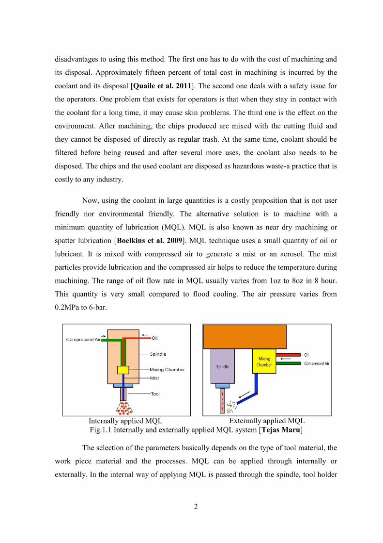
Fig.1.1 Internally and externally applied MQL system [Tejas Maru]
The selection of the parameters basically depends on the type of tool material, the
work piece material and the processes. MQL can be applied through internally or
externally. In the internal way of applying MQL is passed through the spindle, tool holder
3
and tool. There are two basic approaches for applying MQL internally. In one method, oil
and compressed air are mixed in an external unit and passed through the spindle and tool
holder. In the other approach, the oil and the compressed air are mixed inside the spindle
and passed through the tool holder. Fig.1.1 shows the internal way of applying MQL, the
oil is passed through tool and external way of applying MQL, the oil is passed through an
external nozzle with spray form. This system is simple, less expensive and effective for
drilling shallow holes and low speed processes like gear cutting and broaching. The
benefits of MQL over flood coolant system [Boelkins]
Promotes longer tool life by reducing friction, ranging from 25 to 500 percent.
Increases productivity in terms of reducing machining time by allowing
machining with higher feed rates.
Chips are clean and dry.
No need to re-circulate the old or foul smelling coolant
Minimum disposal cost as mostly mist evaporates during machining.
Machine as well as machining area remains clean and hence a much safer
working area.
No coolant tank for coolant and no significant filtering system is required.
The entire process is environmental friendly, as the fluid does not need to be
treated, recycled or disposed of.
1.1 Literature Review
Minimum Quantity Lubrication (MQL) is the process of applying a minute
amount of a quality lubricant directly in to the cutting tool-work piece interface. This is
effective in a variety of metal cutting processes i.e. drilling, tapping, milling and turning.
In view of green manufacturing, dry machining has drawn much attention from industries
recently. Improvement of tool coating technology has facilitated the complete elimination
of cutting fluid in some machining processes. The cutting fluids are still required due to
the high friction and adhesion tendency between works and tool materials for difficulty of
chip and heat removal.
Minimum quantity lubrication refers to the use of cutting fluids of only a minute
amount–typically of a flow rate of 50 to 500 ml/hour–which is about three to four orders of
4
magnitude lower than the amount commonly used in flood cooling condition. The concept
of minimum quantity lubrication, sometimes referred to as “near dry lubrication” [Klocke
and Eisennbla¨tter 1997] or “micro lubrication” [MaClure et al. 2007], has been
suggested since a decade ago as a means of addressing the issues of environmental
intrusiveness and occupational hazards associated with the airborne cutting fluid particles
on factory shop floors. The minimization of cutting fluid also leads to economical benefits
by way of saving lubricant costs and work piece/tool/machine cleaning cycle time.
MQL is important because the lubricant must be compatible with the environment
and resistant to long term usage caused by low consumption [Wakabayashi et al. 2006].
In MQL, lubrication is obtained via the lubricant, while a minimum cooling action is
achieved by the pressurized air that reaches the tool/work interface. Further, MQL reduces
induced thermal shock and helps to increase the work piece surface integrity in situations
of high tool pressure (Attanasio et al. 2006]
MQL, also known as “Micro lubrication” [MaClure et al. 2007] is the latest
technique of delivering metal cutting fluid to the tool/work interface. Using this
technology, a little fluid, when properly selected and applied, can make a substantial
difference in how effectively a tool performs. In conventional operations utilizing flood
coolant, cutting fluids are selected mainly on the basis of their contributions to cutting
performance. In MQL however, secondary characteristics are important. These include
their safety properties, (environment pollution and human contact), biodegradability,
oxidation and storage stability.
In May 2007, an article was published by Tech Solve, based on a comparison
between flood and micro-lubrication [MaClure et al. 2007]. The lubricant used was
Experimental vegetable oil based soluble oil (10%). The flow rates used for flood and mist
conditions were 1.7 gm/min and 0.0029 gm/min respectively. Experiments were conducted
for drilling and milling operations. For the drilling operation the material used was AISI
4340 Steel (32-34 HRC). Speed, feed rate and depth of cut were 55 sfpm, 0.007 ipr and
0.006 inch respectively. The drill used was 0.5 inch heavy duty, oxide coated and high
speed steel with a 135° split point. Analysis showed no significant differences in tool life
(number of holes to reach end of life criteria) between mist and flood cooling. They were
60 and 61 holes for flood and mist conditions respectively. The average thrust forces were

5
570 lbs and 447 lbs for flood and mist cooling respectively. For the milling operation the
material used was AISI 4140 Steel (24-26 HRC). Speed, feed rate and depth of cut were
400 sfpm, 0.005 ipr and 0.5 inch respectively. The cutter body was RA2 15.44-25 MN25 –
15 C (1 inch diameter) and the cutter insert was R215.44-15T308AAM (grade SM-30
uncoated carbide). Analysis showed little differences in tool life (number of holes to reach
end of life criteria) between mist and flood cooling. There were 66 and 80 holes for flood
and mist conditions respectively [MaClure et al. 2007].
It is showed that MQL helps to reduce the cutting temperature and dimensional
inaccuracy when turning of AISI 1040 steel was cut by an uncoated carbide insert by
[Dhar et al. 2006]. The results obtained in MQL were compared with dry cutting and wet
cooling conditions. Different sets of cutting speeds and feed rates were used to compare
the effectiveness of dry, wet and MQL cooling conditions. The air pressure of 7-bar and a
flow rate of 60 ml/h were used in MQL. Cutting speeds were: 64, 80, 110 and 130 m/min
and feed rates were: 0.1, 0.13, 0.16 and 0.2 mm/rev. The effectiveness of the cooling
media was observed by measuring the tool-chip interface temperature, the chips’ shapes
and color, the chip reduction co-efficient and the dimensional deviation at different cutting
speeds and feed rates. The tool-chip interface temperature was observed to be the lowest
when machining was done with a feed rate of 0.1 mm/rev and a cutting speed of 130
m/min under MQL. When the feed rate was set to 0.2 mm/rev, the temperatures were
recorded as 790°C, 775°C and 760°C for dry, wet and MQL conditions respectively. The
trend of cutting temperature decreased when the feed rates and cutting speeds were
decreased. To determine the dimensional accuracy, the experiment was run at the cutting
speed of 110 m/min, a feed rate at 0.2 mm/rev and a depth of cut at 1mm. It was observed
that for a cutting length of 425mm, the dimensional deviation was minimum (about 70μm)
under MQL and maximum (95μm) under dry cutting condition. The study concluded that
MQL provides benefits mainly due to the reduction in cutting temperature, which
improves the tool-chip interaction and maintains the sharpness of the cutting edges. MQL
reduced tool tip wear and damages and because of this, dimensional accuracy improved.
The effects of MQL in turning AISI 1040 steel at high cutting speeds were
investigated again by Dhar et al. [2006]. During the experiment the factors: cutting forces,
cutting temperature, chip reduction coefficient, average flank wear, auxiliary flank wear,
6
surface finish and dimensional accuracy were measured to see the effect of MQL with
different sets of cutting speeds and feed rates. Work material AISI 1040 Cutting tool
material Carbide inserts Cutting speed 72, 94, 139 and 164 m/min Feed rate 0.10, 0.13,
0.16, 0.20 mm/rev Depth of cut 1.5mm Air pressure in MQL supply 8 bar Flow rate of
MQL supply 200ml/h Cutting environment Dry and MQL method It was observed in the
experiment conducted by Dhar et al. that MQL helped to reduce the cutting temperature
approximately by 5-10% compared with dry cutting for each combination of cutting speed
and feed. The general trend indicates that with an increase in cutting speed, cutting
temperature is also increased, but the cutting temperature in MQL is lesser than that of dry
cutting. Cutting force and feed force play vital role for power and energy consumption,
product quality, and life of other members
The Machining processes have an important place in the traditional production
industry. Cost effectiveness of all machining processes has been eagerly investigated. This
is mainly affected selection of suitable machining parameters like cutting speed, feed rate
and depth of cut according to cutting tool and work piece material. The selection of
optimum machining parameters will result in longer tool life, better surface finish and
higher material removal rate. During machining process, friction between work piece
cutting tool and cutting tool-chip interfaces cause high temperature on cutting tool. The
effect of this generated heat decreases tool life, increases surface roughness and decreases
the dimensional sensitiveness of work material. This case is more important when
machining of difficult-to-cut materials, when more heat would be observed [Silva and
Wallbank 1998].
Various methods have been reported to protect cutting tool from the generated
heat. Choosing coated cutting tools are an expensive alternative and generally it is a
suitable approach for machining some materials such as titanium alloys, heat resistance
alloys etc. The application of cutting fluids is another alternative to obtain higher material
removal rates. Cutting fluids have been used widespread in all machining processes.
However, because of their damaging influences on the environment, their applications
have been limited in machining processes [Brinksmeier et al. 1999, Sokovic and
Mijanovic 2001, Bartz 2001, Baradie 1996 and Baradie 1996].
7
New approaches for elimination of cutting fluids application in machining
processes have been examined and “dry machining” was presented as an important
solution [Sreejith and Ngoi 2000, Popke et al. 1999]. The development of new cutting
tool materials also helped dry machining method to be a positive solution for cutting fluids
applications. However, the usage of cutting fluids has been increased due to high
production levels in the world. Approximately 2.3x10⁹ liter cutting fluids have been used
in the machining operations and its cost value was around $ 2.75x10⁹ [Popke et al. 1999].
North America had a big ratio; Europe continent was in the third order after Asia
continent [Popke et al. 1999]. The first study about cutting fluids had been
determined by [Northcott 1868] with a book entitled “A treaties on lathes and turning”.
In the middle of 1890’s, F.W. Taylor emphasized that using cutting fluids would allow to
use higher cutting speeds resulting in longer tool life’s and higher material removal rates
[Avuncan 1998]. It had been concluded that the application of cutting fluids in machining
processes would make shaping process easier [DeGarmo et al. 1984 and Shaw 1991].
In early research paper had commented that because of the vast scale on which
drilling operations were carried out, even a slight increase in the general level of drill
performance would yield important practical and economic benefits to individual firms and
the engineering industries as a whole [Galloway 1957]. In addition, drilling problems can
usually result in costly production waste since most of the drilling operations are the final
steps in fabricating a part [Strenkowski et al. 2004].
The early types of drills, which were mostly made of rough, flat bars of steel,
suffered from a serious chip disposal problem which required frequent interruptions during
drilling to clear the chips in order to reach the proposed hole depth. This resulted in low
production rate and frequent replacement of worn tools [Kang 1997]. As a consequence,
the application of the early types of drills was rather limited and numerous attempts had
ever been made to seek more efficient drill designs.
The Intensive research works were conducted in the last few years for this reason
Minimum Quantity Lubrication (MQL) is now an established alternative to conventional
flood cooling in drilling [Weinert 1999 and Klocke et al. 1996].
8
Minimum quantity lubrication also results in a satisfactory tool life for small
diameter drills when deep hole drilling, as very recent work has revealed [Heinemann
2004]. Current research work is directed towards determining the optimum amount and the
most appropriate type of minimum quantity lubricant so that the longest tool life is
achieved. However, a vital question that still remains unanswered: is the complete absence
of any coolant a viable alternative to MQL without jeopardizing process stability and tool
life? With respect to the amount of lubricant supplied, not only is the total amount, in
terms of volume per unit of time, of interest but also the manner in which it is supplied.
MQL is of importance because of the limited penetration capability of cutting
fluids into a borehole during the drilling process. Once the hole depth exceeds 2–3 times
the drill diameter, very little or no cutting fluid can reach the drill tip mainly because the
drill and the counter-flow of chips restrict further penetration [Weinert 1999, Klocke and
Gerschwiler 1996].
Hence, drilling at a depth exceeding 3 times the hole diameter has to be
considered as a near-dry cutting process, even when large amounts of cutting fluid are
poured towards the tool. Thus, supplying a cutting fluid throughout a drilling cycle might
be considered as a waste of lubricant as no significant advantage in terms of improved
lubrication and/or cooling of the drill might be achieved. It merely spoils the process’s
efficiency. This restricted provision is supposed to be the main reason why MQL very
often brings about an advantage in drilling compared to flood cooling.
In contrast to MQL, dry machining has not fully established itself in drilling
technology, mainly because of the extremely high thermal load on the drilling tools
resulting in accelerated tool wear and unsatisfying overall process stability [Klocke and
Gerschwiler 1996]. The importance of cooling in drilling was demonstrated by Rehbein
[Rehbein and Bohren 1999] who was able to prolong the tool life by blending the
minimum quantity lubricant with water.
In many cases the decrease in temperature due to a reduction in friction is not
sufficient to keep the tool at a tolerable temperature and thus the lubrication is most
effective at low cutting speeds, whereas cooling becomes increasingly important at higher
cutting speeds. Since drilling is supposed to be a high-speed operation, lubrication cannot
9
occur, because the lubricant cannot penetrate into the tool–work piece interface quickly
enough [Haan et al. 1997].
According to the U.S. Occupational Safety and Health Administration (OSHA)
[Aronson 1995] and the U.S. National Institute for Occupational Safety and Health
(NIOSH) the permissible exposure level (PEL) for metal working fluid aerosol
concentration is 5 mg/m³ and 0.5 mg/m³ respectively. The oil mist level in U.S. automotive
parts manufacturing facilities has been estimated to be 20-90 mg/m³ with the use of
conventional lubrication by flood coolant [Bennett and Bennett 1985]. The exposure of
such amounts of metal working fluid can cause adverse health effects and safety issues,
including toxicity, dermatitis, respiratory disorders and cancer. When considering large
system quality, the recirculating coolant in cleanliness and concentration overtime results
in variation of tool wear and affects part finish and dimensions. In flood coolant, the
trenches and hard piping for a recirculating coolant system hinders the rapid
reconfiguration of equipment. In conventional flood coolant, wet chips are produced, that
have to be dried before remelting, which incurs cost. But MQL produces dry chips, so the
cost of drying chips is reduced [Filipovic and Stephenson 2006].
In 2003, a study was conducted in Japan to investigate the Tribological behavior
of lubricants for semi-dry application in connection with cutting performance
[Wakabayashi et al. 2003]. Two kinds of synthetic biodegradable esters and a rapeseed
vegetable oil were used. One is a fully synthetic polyol ester the other is a vegetable based
synthetic ester. For comparison, neat type cutting oil is used for conventional flood supply.
Cemented carbide or Cermet was used as the cutting tool and the work-piece material was
JIS (Japan Industrial Standards) S45C carbon steel.
A cutting speed of 200 m/min was used with a feed of 0.1 mm/rev and a depth of
cut of 1 mm. MQL was supplied with a pressure of 0.3 MPa and flow rate of 25 ml/h
through an external nozzle. The experiments were conducted in a vacuum chamber. When
the chamber pressure was 1.0 × 10⁻⁴ Pa, a two gas component was introduced into the
chamber. After the chamber flow was constant by inlet and outlet gas, machining was
carried out. The result indicated cutting performance in MQL machining in ester is
superior to that in dry machining. MQL machining with vegetable oil with viscosity of
35.6 mm2 / s was not preferred. The surface roughness by MQL machining with ester oil
10
was just below 1 Ra, μm as compared to vegetable oil which was 1.25 Ra, μm. The
coefficient of friction for ester oil was approximately 1.48 and for vegetable oil 1.52. For
tool rake surface analysis, an electron probe microanalysis (EPMA) was done which
provided detailed information about surface elements. According to this analysis carbon
was significantly observed on the tool face in MQL machining with synthetic ester oil.
This analysis implied the possibility of strong absorption of polyol ester on to the tool
surface. Such carbon does not exist in MQL using vegetable oil. This lack is probably the
reason why the cutting performance of synthetic ester was better than vegetable oil
[Wakabayashi et al. 2003].
In the initial stages of MQL development low quantities (such as 200 – 300 ml/hr)
of lubricants were used in machining Operation [Machado and Wallbank 1997]. These
low quantities were applied in fast flowing air streams. It was proved that MQL was more
efficient when low cutting speeds and high feed rates are used (i.e. cutting speed of 200
m/min and feed rate of 0.15 mm/rev). Cutting and feed force are reduced when machining
a medium carbon steel under low cutting speed and high feed rates. The mixture of air-
water or air-soluble oil reduces the amplitude of oscillation of the force component. For
producing these two mixtures a venturi was designed to mix compressed air with small
quantities of a liquid lubricant (water and soluble oil). This venturi ends with a nozzle that
directs the mixture onto the rake face of the tool. A pressure regulator and valve were
placed between the air compressor and venturi. With the valve shut the air pressure was set
to 2.3 bars (34 psi). With the valve fully open the pressure dropped to 2 bars. For water,
the mean flow rate was 293.98 ml h-1. For soluble oil, the mean flow rate was 195.76 ml
h-1. A P40 uncoated steel cutting grade cemented carbide insert (S6) having SNMG
120404 ISO specification and a CSSNR 3225 M12 tool holder, manufactured by Sandvik
were used in all tests. AISI 1040 normalized forged steel bars were used as work materials.
The machine tool was a Torshalla S250 CNC lathe with 30 kW of power. Due to the
application of mist, an effective exhaust extraction system was required. Cutting and feed
force are reduced when a lubricant is applied when machining a medium carbon steel
under low cutting speed and high feed rates. Mixtures of air-water or air-soluble oil reduce
the amplitude of oscillation of the forced component. The influence of the lubrication is
noticeable for low cutting speed and high feed rates, with mixtures of air-water and air-
soluble oil outperforming other lubricant conditions tested. The results with air-water
11
combinations were found to be encouraging. This result avoids pollution of the
environment and related problems of health and safety, and drastically reduces lubricant
costs, although it may cause problems of corrosion. The Experiments of MQL were
conducted using diamond-coated and uncoated tools [Braga et al. 2002]. The coating
improvement of carbide tools and the chemical and mechanical properties of the tool
material have caused an increase in tool working life in machining processes. When a
diamond coated tool was used, the result was an irregular surface wear of the drill and a
decrease in hole quality, compared with the uncoated K10 drill. The experiments were
carried out in a rigid CNC machining center with 22 kW of power and maximum rotation
of 12,000 rpm. Drills used in the experiments were made of uncoated ISO K10 carbide
(NS kind), according to DIN 338 and diamond coated carbide. The K10 carbide drills had
an average diameter of 9.986 mm and the diamond drills had an average diameter of 9.992
mm (both with tolerance ISO h8). The work-pieces were made of aluminum–silicon alloy
with 7% silicon (SAE 323). The conclusion is the process performance (in terms of forces,
tool wear and quality of holes), when using MQL, was similar to that obtained when using
a high amount of soluble oil, with both, coated and uncoated K10 drills. These conclusions
prove the potential of using this technique in the drilling process for aluminum-silicon
alloys. In this experiment two cooling systems were used. The first was a mixture of air
and oil (MQL): 10 ml/h of mineral oil was pulverized in an air flow of 72 m³/h and 4.5 bar
of pressure. The second system was a flood of soluble oil (1 part oil to 25 parts water) with
a flow rate of 2.4m³/h. For both systems, the condition and tools, a cutting speed of 300
m/min and feed of 0.1 mm/rev were used. It was observed that the value of flank was
similar when using an uncoated K10 drill, (after 612 holes the difference in flank wear was
less than 0.050mm). The values of power consumed for the two drill materials, when using
MQL were similar at 0.81 and 0.79 Kw for diamond coated and uncoated tools
respectively at 20 m feed length. Feed force represented almost the same rate of increase
with feed length for all experiments regardless of the cutting condition and tool material.
The uncoated K10 drill presented the best results related to the average diameter of the
hole. For the diamond coated drill, results are better when MQL was used. For uncoated
drills results are similar for both cooling systems [Braga et al. 2002].
Hole making had long been recognized as the most prominent machining process,
requiring specialized techniques to achieve optimum cutting condition. Drilling can be
12
described as a process where a multi-point tool is used to remove unwanted materials to
produce a hole. It broadly covers those methods used for producing cylindrical holes in the
work piece. While removal of material in the form of chips new surfaces are cleaved from
the work piece accompanied by a large consumption of energy. The mechanical energy
necessary for the drilling operation is transformed in to heat leading to conditions of high
temperature and severe thermal / frictional conditions at the tool- chip interface [Ezugwu
and Lai 1995].
The magnitude of the cutting temperature increases though in different degree
with the increase of cutting velocity, feed and depth of cut. At such elevated temperature
the cutting tools if not enough hot hard may lose their form stability quickly or wear out
rapidly resulting in increased cutting force, dimensional inaccuracy of the product and
shorter tool life [Kitagawa et al. 1997]. This problem increases further with the increase
in strength and hardness of the work material.
During drilling process, the most important factor affecting the cutting tool
performance and work piece properties is cutting temperature that emerges between drill
bit and chip [Eyup and Babur 2006]. The cutting temperature directly influences hole
characteristics such as diameter, perpendicularity and cylindricity, as well as surface
roughness and tool wear [Eyup and Babur 2006]. They also investigated the effects of
cutting depth, cutting speed, web thickness and helix angle on the temperature. The
temperatures associated with the drilling process are particularly important, because
drilling is one of the predominant industrial machining processes and heat effects in
drilling are generally more severe than in other metal cutting operations. Drills often
experience excessive temperatures because the drill is embedded in the work piece and
heat generation is localized in a small area. The resulting temperatures can lead to
accelerate tool wear and reduce tool life and they can have profound effects on the overall
quality of the machined work piece. Drill designers often select the geometrical features of
a drill based on the expected temperature profile in the drill point, so accurate prediction of
the temperature distribution is imperative [Matthew and Jun 2006]. Temperature not only
be exaggerated the tool wear but also affect the surface, hole quality and chip formation.
The cutting temperature directly influences hole sensitivity, surface roughness, and tool
wear [Eyup and Babur 2006]. A turning tool typically will not fail due to thermal shock,

13
because it is subjected to this quenching only three or four times per minute when it is
withdrawn from the cut at the end of each pass. A face milling operation running at 1000
rpm, on the other hand, subjects every insert to 1000 damaging quenches per minute.
Drilling fails somewhere in between with thermal shock occurring every time the drill
pulls out of the cut [Gregory 1999].
A major portion of the energy is consumed in the formation and removal of chips.
The greater the energy consumption, the greater are the temperature and frictional forces at
the tool–chip interface and consequently the higher is the tool wear [Senthil Kumar et al
2002]. Drill wear not only affects the surface roughness of the hole but also influences the
life of the drill bit [Panda et al. 2006]. Wear in drill bit is characterized as flank wear,
chisel wear, corner wear, crater wear and margin wear [Panda 2006 and Sanjay 2005].
Since wear on drill bit dictates the hole quality and tool life of the drill bit [Panda et al.
2006].
Worn drills produce poor quality holes and in extreme cases, a broken drill can
destroy almost all finished parts. A drill begins to wear as soon as it is placed into
operation. As it wears, cutting forces increases, the temperature rises and this accelerates
the physical and chemical processes associated with drill wear and therefore drill wears
faster [Sanjay et al. 2005]. Thrust and torque depend upon drill wear, drill size, feed rate
and spindle speed. Researches results show that tool breakage, tool wear and work piece
deflection are strongly related to cutting force [Sanjay et al. 2005].
The material is removed in the form of chips and evacuated through the drill
flutes. It has been demonstrated [Litvinov 1990, Ackroyd 1998 and Sahu 2003] that
smaller chips are more easily removed from the drill by the action of the flutes, centrifugal
forces, and/or metal working fluids. Long chips can become tangled around the drill, can
lead to poor hole quality and are more difficult to manage once outside the hole thereby
increasing production costs and lowering productivity. Furthermore, while drilling deep
holes friction between the drill flutes and chips causes the chips to be evacuated slower
than chips are produced. This leads to chip clogging, which in turn causes sudden increase
in torque and thrust that may cause drill breakage. Improved chip evacuation will lead to
less drill breakage, lower production costs, better hole quality, and increase productivity
[Degenhardt et al. 2005].
14
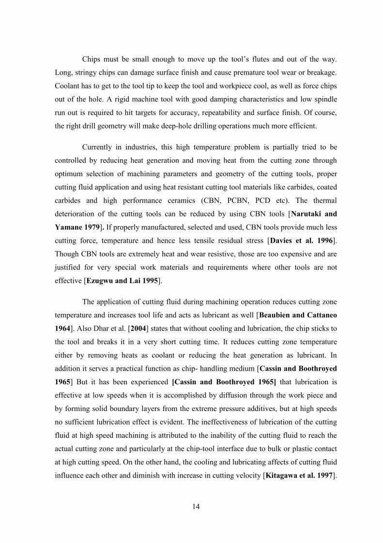
Chips must be small enough to move up the tool’s flutes and out of the way.
Long, stringy chips can damage surface finish and cause premature tool wear or breakage.
Coolant has to get to the tool tip to keep the tool and workpiece cool, as well as force chips
out of the hole. A rigid machine tool with good damping characteristics and low spindle
run out is required to hit targets for accuracy, repeatability and surface finish. Of course,
the right drill geometry will make deep-hole drilling operations much more efficient.
Currently in industries, this high temperature problem is partially tried to be
controlled by reducing heat generation and moving heat from the cutting zone through
optimum selection of machining parameters and geometry of the cutting tools, proper
cutting fluid application and using heat resistant cutting tool materials like carbides, coated
carbides and high performance ceramics (CBN, PCBN, PCD etc). The thermal
deterioration of the cutting tools can be reduced by using CBN tools [Narutaki and
Yamane 1979]. If properly manufactured, selected and used, CBN tools provide much less
cutting force, temperature and hence less tensile residual stress [Davies et al. 1996].
Though CBN tools are extremely heat and wear resistive, those are too expensive and are
justified for very special work materials and requirements where other tools are not
effective [Ezugwu and Lai 1995].
The application of cutting fluid during machining operation reduces cutting zone
temperature and increases tool life and acts as lubricant as well [Beaubien and Cattaneo
1964]. Also Dhar et al. [2004] states that without cooling and lubrication, the chip sticks to
the tool and breaks it in a very short cutting time. It reduces cutting zone temperature
either by removing heats as coolant or reducing the heat generation as lubricant. In
addition it serves a practical function as chip- handling medium [Cassin and Boothroyed
1965] But it has been experienced [Cassin and Boothroyed 1965] that lubrication is
effective at low speeds when it is accomplished by diffusion through the work piece and
by forming solid boundary layers from the extreme pressure additives, but at high speeds
no sufficient lubrication effect is evident. The ineffectiveness of lubrication of the cutting
fluid at high speed machining is attributed to the inability of the cutting fluid to reach the
actual cutting zone and particularly at the chip-tool interface due to bulk or plastic contact
at high cutting speed. On the other hand, the cooling and lubricating affects of cutting fluid
influence each other and diminish with increase in cutting velocity [Kitagawa et al. 1997].
15
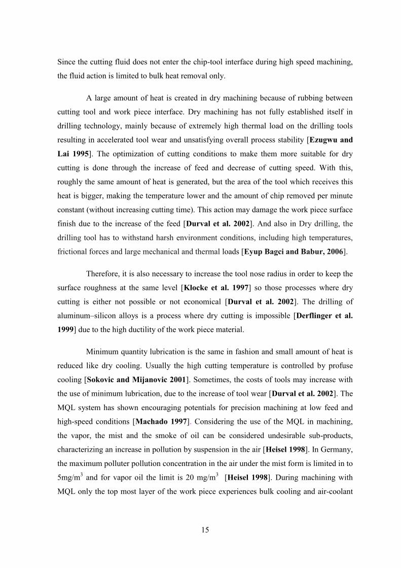
Since the cutting fluid does not enter the chip-tool interface during high speed machining,
the fluid action is limited to bulk heat removal only.
A large amount of heat is created in dry machining because of rubbing between
cutting tool and work piece interface. Dry machining has not fully established itself in
drilling technology, mainly because of extremely high thermal load on the drilling tools
resulting in accelerated tool wear and unsatisfying overall process stability [Ezugwu and
Lai 1995]. The optimization of cutting conditions to make them more suitable for dry
cutting is done through the increase of feed and decrease of cutting speed. With this,
roughly the same amount of heat is generated, but the area of the tool which receives this
heat is bigger, making the temperature lower and the amount of chip removed per minute
constant (without increasing cutting time). This action may damage the work piece surface
finish due to the increase of the feed [Durval et al. 2002]. And also in Dry drilling, the
drilling tool has to withstand harsh environment conditions, including high temperatures,
frictional forces and large mechanical and thermal loads [Eyup Bagci and Babur, 2006].
Therefore, it is also necessary to increase the tool nose radius in order to keep the
surface roughness at the same level [Klocke et al. 1997] so those processes where dry
cutting is either not possible or not economical [Durval et al. 2002]. The drilling of
aluminum–silicon alloys is a process where dry cutting is impossible [Derflinger et al.
1999] due to the high ductility of the work piece material.
Minimum quantity lubrication is the same in fashion and small amount of heat is
reduced like dry cooling. Usually the high cutting temperature is controlled by profuse
cooling [Sokovic and Mijanovic 2001]. Sometimes, the costs of tools may increase with
the use of minimum lubrication, due to the increase of tool wear [Durval et al. 2002]. The
MQL system has shown encouraging potentials for precision machining at low feed and
high-speed conditions [Machado 1997]. Considering the use of the MQL in machining,
the vapor, the mist and the smoke of oil can be considered undesirable sub-products,
characterizing an increase in pollution by suspension in the air [Heisel 1998]. In Germany,
the maximum polluter pollution concentration in the air under the mist form is limited in to
5mg/m3 and for vapor oil the limit is 20 mg/m3 [Heisel 1998]. During machining with
MQL only the top most layer of the work piece experiences bulk cooling and air-coolant
16
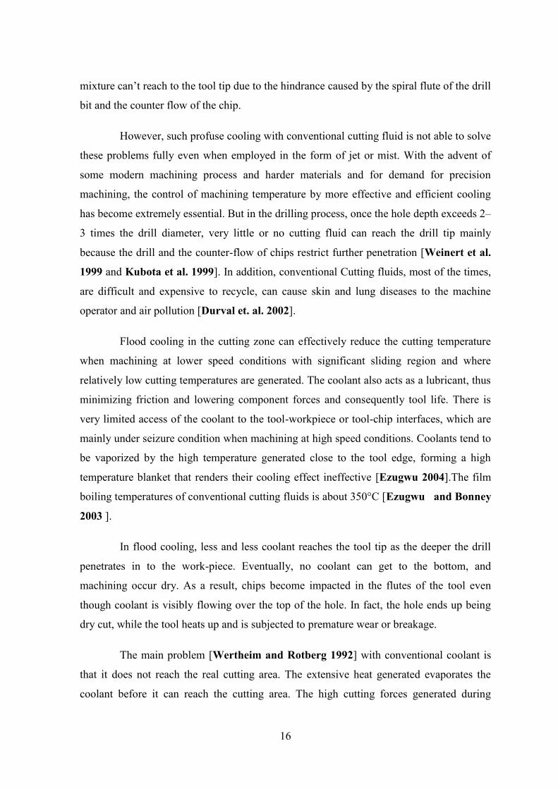
mixture can’t reach to the tool tip due to the hindrance caused by the spiral flute of the drill
bit and the counter flow of the chip.
However, such profuse cooling with conventional cutting fluid is not able to solve
these problems fully even when employed in the form of jet or mist. With the advent of
some modern machining process and harder materials and for demand for precision
machining, the control of machining temperature by more effective and efficient cooling
has become extremely essential. But in the drilling process, once the hole depth exceeds 2–
3 times the drill diameter, very little or no cutting fluid can reach the drill tip mainly
because the drill and the counter-flow of chips restrict further penetration [Weinert et al.
1999 and Kubota et al. 1999]. In addition, conventional Cutting fluids, most of the times,
are difficult and expensive to recycle, can cause skin and lung diseases to the machine
operator and air pollution [Durval et. al. 2002].
Flood cooling in the cutting zone can effectively reduce the cutting temperature
when machining at lower speed conditions with significant sliding region and where
relatively low cutting temperatures are generated. The coolant also acts as a lubricant, thus
minimizing friction and lowering component forces and consequently tool life. There is
very limited access of the coolant to the tool-workpiece or tool-chip interfaces, which are
mainly under seizure condition when machining at high speed conditions. Coolants tend to
be vaporized by the high temperature generated close to the tool edge, forming a high
temperature blanket that renders their cooling effect ineffective [Ezugwu 2004].The film
boiling temperatures of conventional cutting fluids is about 350°C [Ezugwu and Bonney
2003 ].
In flood cooling, less and less coolant reaches the tool tip as the deeper the drill
penetrates in to the work-piece. Eventually, no coolant can get to the bottom, and
machining occur dry. As a result, chips become impacted in the flutes of the tool even
though coolant is visibly flowing over the top of the hole. In fact, the hole ends up being
dry cut, while the tool heats up and is subjected to premature wear or breakage.
The main problem [Wertheim and Rotberg 1992] with conventional coolant is
that it does not reach the real cutting area. The extensive heat generated evaporates the
coolant before it can reach the cutting area. The high cutting forces generated during
17
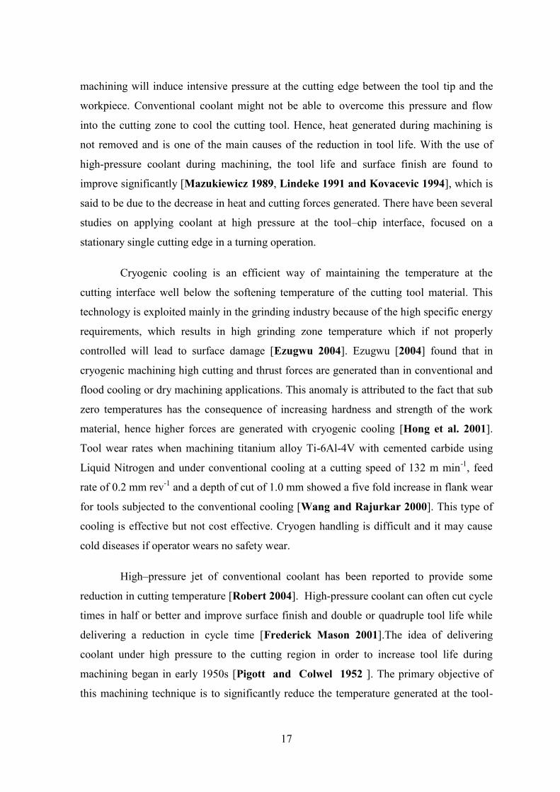
machining will induce intensive pressure at the cutting edge between the tool tip and the
workpiece. Conventional coolant might not be able to overcome this pressure and flow
into the cutting zone to cool the cutting tool. Hence, heat generated during machining is
not removed and is one of the main causes of the reduction in tool life. With the use of
high-pressure coolant during machining, the tool life and surface finish are found to
improve significantly [Mazukiewicz 1989, Lindeke 1991 and Kovacevic 1994], which is
said to be due to the decrease in heat and cutting forces generated. There have been several
studies on applying coolant at high pressure at the tool–chip interface, focused on a
stationary single cutting edge in a turning operation.
Cryogenic cooling is an efficient way of maintaining the temperature at the
cutting interface well below the softening temperature of the cutting tool material. This
technology is exploited mainly in the grinding industry because of the high specific energy
requirements, which results in high grinding zone temperature which if not properly
controlled will lead to surface damage [Ezugwu 2004]. Ezugwu [2004] found that in
cryogenic machining high cutting and thrust forces are generated than in conventional and
flood cooling or dry machining applications. This anomaly is attributed to the fact that sub
zero temperatures has the consequence of increasing hardness and strength of the work
material, hence higher forces are generated with cryogenic cooling [Hong et al. 2001].
Tool wear rates when machining titanium alloy Ti-6Al-4V with cemented carbide using
Liquid Nitrogen and under conventional cooling at a cutting speed of 132 m min-1, feed
rate of 0.2 mm rev-1 and a depth of cut of 1.0 mm showed a five fold increase in flank wear
for tools subjected to the conventional cooling [Wang and Rajurkar 2000]. This type of
cooling is effective but not cost effective. Cryogen handling is difficult and it may cause
cold diseases if operator wears no safety wear.
High–pressure jet of conventional coolant has been reported to provide some
reduction in cutting temperature [Robert 2004]. High-pressure coolant can often cut cycle
times in half or better and improve surface finish and double or quadruple tool life while
delivering a reduction in cycle time [Frederick Mason 2001].The idea of delivering
coolant under high pressure to the cutting region in order to increase tool life during
machining began in early 1950s [Pigott and Colwel 1952 ]. The primary objective of
this machining technique is to significantly reduce the temperature generated at the tool-

18
workpiece and tool-chip interfaces when cutting at higher speed conditions. This is
achieved by directing coolant under high pressure at the chip-tool interface. This process
can also achieve high chip breakability and control through increased chip up curl and
compressive stress [Ezugwu 2004]. Ezugwu [2004] stated that ability to deliver coolant at
high pressure very close to the critical point on the secondary shear zone can improve
machinability at higher speed conditions. The credibility of this technique of coolant
delivery has been thoroughly investigated over the years. The high speed coolant jet
traverses the surface faster, thus significantly lowering the film boiling action of the
coolant at the cutting area. This consequently minimizes heat transfer to the cutting tool.
The high pressure coolant jet creates a hydraulic wedge between the tool and the
workpiece, penetrating the interface with a speed exceeding that required even for high
speed machining and also alters the chip flow conditions [Mazurkiewicz 1989]. The
penetration of the high energy jet into the tool-chip interface reduces the temperature
gradient and eliminates the seizure effect, offering an adequate lubrication at the tool-chip
interface with a significant reduction in friction [Ezugwu 2004].
The temperatures generated by the cutting speeds of today’s advanced tooling can
actually prevent low-pressure flood coolant from entering the cutting zone. The majority of
the cooling and lubricating aspects of a flood coolant stream are lost as the coolant is
vaporized prior to entering the cutting zone [Frederick Mason 2001]. It is the great
problem for machining, HPC play well role to minimize this type of problem. Frederick
Mason [2001] found better solution from it and he states that HPC systems generates high
velocity coolant streams moving at several hundred mph. This high-speed coolant easily
penetrates the vapor barrier to effectively lubricate and cool the tool. In fact, when
machinists apply high-pressure coolant to a longstanding process, which has always
produced dark blue chips, they are often amazed that the same or even higher speeds and
feeds produce shiny, silver chips that are cool to the touch.
Heat from the drill may also work harden or “heat treat” the workpiece in the
vicinity of the hole. Friction from the drill heats the workpiece, and when coolant finally
reaches the heated material, the coolant quenches it. On the subsequent peck, the drill
encounters the hardened material, causing excessive tool wear or a broken tool and
damaged part. The high pressure of the coolant breaks up chips and forces them up the
19
flutes and out of the hole. Cycle times go down, because the pecking process is eliminated
while spindle speeds and feed rates can be increased. With higher feed rates, chips tend to
form better.
The need for high pressure and high volume coolant in drilling became apparent
when gun drills came into use over 100 years ago. The essence of the problem (then and
now) with standard low pressure coolant systems is that so much heat is produced that the
coolant boils away before it can reach the chip- tool interface where metal is actually cut.
The super heated steam forms a barrier that low pressure coolant can’t penetrate. Effective
cooling does not occur and there is little real lubrication provided. Unfortunately, the vapor
barrier that forms is not powerful enough to keep chips from falling back into the chip-tool
interface and causing damage. Properly applied high pressure and high volume coolant
prevents this vapor barrier from forming by causing a localized pressure increase. So much
liquid is forced into the cutting zone that heat is removed and no vapor can form because
of the pressurization. When machinists tried high-pressure coolant on standard drilling
operations, they found that the benefits of increasing coolant pressure improved the
performance of these operations as well. Properly applied high-pressure, high-volume
coolant prevents the formation of a vapor barrier by causing a localized pressure increase.
This force is liquid into the cutting zone, removing heat, providing lubrication, and
flushing chips away from the cut. Damage from heat and chips is eliminated, and tools can
cut until they wear out. High-pressure coolant discourages chip welding, prevents the
damaging chemical reactions that may occur at high temperatures, and allows drills to last
longer [Gregory 1999].
Deep hole drilling with a depth of ten times the hole diameter is used in the
automobile industry. In the initial development of deep hole drilling using MQL, a depth
of 5 times the diameter showed that vibration drilling is effective to a depth of 5 times the
diameter [Hidetaka and Hideyo 1996]. In this study, drilling a depth of 10 times the
diameter was done. A drill of 3mm diameter was used with an overall length of 71mm and
point angle of 118°. The cutting condition for both the vibration drilling and conventional
drilling were the same. Work material used was SS400. Cutting speed was based on 1700
rev/min. Feed rate was 0.008, 0.16, 0.20 and 0.24 mm/rev. Cutting fluid used was Neat oil
type: JIS (2-1). When deep holes were drilled the contact resistance between the chip
20
edges and hole walls increases and produces chip congestion. Increase of feed speed helps
to prevent this congestion. Vibration drilling disposes of chips at a fast speed because it
accelerates the penetration of oil and produces a large variation of chip thickness. Disposal
in vibration drilling extends drill life in comparison with conventional drilling. A study
was conducted at Georgia Institute of Technology to compare the mechanical performance
of minimum quantity lubrication over completely dry lubrication for the turning of
hardened bearing-grade steel materials with low content CBN cutters [Autret and Liang
2003]. Process attributes analyzed were surface roughness, cutting temperature, cutting
forces, and tool life. A range of feeds from 0.002 to 0.014 inch/rev, cutting speeds of 450
sfpm and depth of cut of 0.012 inch were tested with a triglyceride and propylene glycol
ester solution vegetable based cutting fluid at a constant flow rate of 50 ml/hour and a
nozzle pressure of 20 psi. The cutting tool used was a low content CBN tool (Kennametal
KD5625) with a rake angle of -6° chamfer length of 0.12 mm, horn radius of 0.03 mm, and
nose radius of 0.8 mm. A slant bed horizontal lathe (Hardinge T42SP) was used [Autret
and Liang 2003].
In the context of resulting surface roughness, no noticeable difference was
concluded with the use of a near-dry over completely dry condition. However, an
improvement of surface finish was felt by near-dry machining under greater depths of cut
and feeds such as 0.012 inch and 0.006 in/rev respectively. In the context of a steady-state
cutting temperature, a 10% to 30% reduction was consistently observed when a minimum
quantity lubrication condition was applied as opposed to completely dry. This result was
expected due to an increase in the evaporative heat transfer at the cutting zone. In the
contest of cutting forces, there was no significant difference with or without the use of
minimum quantity lubrication. The cutting force was approximately 250 N at a feed of
0.012 in/rev. In the context of tool life, the study showed a significant increase from 35%
to 50% by minimum quantity lubrication over a wide range of cutting conditions [Autret
and Liang 2003].
In 2006, a paper published in Machining Science and Technology Journal
introduced synthetic polyol esters and described their capacity as a potential MQL fluid,
particularly compared with vegetable-based MQL oils, from the viewpoint of optimal
secondary performance for MQL operations [Wakabayashi et al. 2006].
21
The studies about cutting fluid application in machining processes have
been evaluated that the selection criteria of cutting fluids have been examined. Suitable
cutting fluids for various material machining processes have been determined according to
cutting tool materials. In drilling operations, a drill rotates while it is fed into a stationary
work piece for the production of holes. The interference and relative motion between the
drill and the work piece result in a cylindrical hole and material removal in the form of
chips. Because of its extensive use, drilling has become an indispensable and important
operation in industry which accounts for a large portion of overall machining times and
costs.
1.1.1 Machinining with Conventional Twist Drills
In the industries, different the machine accessories and different aircrafts
accessories manufacturing purpose, different hard metals are drilled by conventional twist
drills and faced with very difficult problem. Different cutting action at the cutting edges of
the conventional twist drills used will be presented. The geometry of any type of twist drill
has been well recognized to have a very complex geometry as compared to other metal
cutting tools.
Obikawa et al. [2006] conducted an experiment on 0.45% carbon steel with
TiC/TiCN/TiN triple layer coated carbide tool. The comparison was done between a P35
coated cemented carbide tool and a P25 uncoated cemented carbide tool. In the
experiment, a P35 tool was used for a 3000 am cutting length and a P25 tool was used for
a 1000 m cutting length. Two cutting speeds were used: 4 m/sec and 5 m/sec. The feed rate
was 0.12 mm/rev. MQL was applied at the rate of 7 ml/h and the flow rate for the
controlled-oil-mist directed grooving tool was set to 2.4 ml/h. The corner edge-wear and
flank wear was measured in dry, wet and MQL cooling conditions. Three different air
pressures were used: 0.3MPa, 0.5MPa and 0.7MPa. When the cutting speed was 4 m/sec,
the feed rate was set to 0.12 mm/rev and the air pressure was set to 0.7MPa. The tool wear
(both corner wear and flank wear) were reduced while machining under MQL condition in
compare to dry for both the cutting tools. Tool wear was minimum in case of P35 grade
cutting tool in compare to P25 grade tool under the same condition. It indicates that the
coating on tool also plays a vital role in machining. It can also be observed that at the
22
higher cutting speed of 5 m/sec, the corner wear in dry cutting increased suddenly due to
the loss of coating layers. MQL reduced the wear to a large extent even at high cutting
speed of 5 m/sec. The results also showed that by increasing the air pressure in MQL from
0.3 MPa to 0.7 MPa, flank wear and corner wear reduced drastically with a constant
supply of MQL by 7ml/h.
The application of MQL in turning operation reduces tool wear, surface
roughness and cutting temperature at the tool-chip-work piece surface contact as reported
by Dhar et al. [2006] who conducted an experiment on the turning of AISI 4340 steel.
Here, Machining was done with carbide inserts at a cutting speed of 110 m/min, a feed rate
of 0.16 mm/rev and a depth of cut of 1.5 mm. The turning operation was done under a dry,
wet (flood cooling) and MQL environment. In MQL, the air pressure was set to 7-bar and
the flow rate at 60 ml/h. The machining was done for about 45 min. During the
experiment, the average principal flank wear, average auxiliary flank wear and surface
roughness were measured for different cutting lengths. It was observed that the wear rate
and the surface roughness value were lesser in MQL compared to dry and wet cooling
conditions. The growth rate of the flank wears decreased in MQL because of the reduction
in temperature at the tool-chip interface area near the flank surface of the tool. Reduction
in temperature helped to reduce abrasion wear by retaining tool hardness and also helped
to reduce abrasion and diffusion types of wear-which are highly sensitive to temperature.
The surface finish of the work piece and the dimensional accuracy depend on the auxiliary
flank wear.
Basically it consists of three parts, i.e. the shank for mounting the drill into the
drilling machine spindle, the body with two helical flutes to provide the required reach to
the cutting part and the point which consists of two lips and one chisel edge as formed by
the corresponding flanks and flutes. The shank is the portion by which the drill is held and
driven. Its function is to transmit the torque and force during a drilling process. Normally,
two different types of shanks are used in practice; namely, straight or cylindrical shank and
tapered shank. The straight or cylindrical shank is used extensively. It usually has the same
diameter as the drill body and the drill diameter ranges from approximately 0.006 to 2 in.
The tapered-shank drills have a standard taper (Morse system) and are designed for the
23
conventional twist drills with a relatively larger size ranging from 1/8 to 3.5 in. as
recommended in [Donaldson et al. 1973].
Generally the shank is made of carbon steel especially for large size drills
considering the fact that HSS is much more expensive than carbon steel. For small sized
drills, the whole body may be made of HSS. Drill body is the central part of a drill that
extends from the shank to the outer corners of the cutting lips at the drill point. The body
consists of two helical flutes or grooves to provide the cutting lips when the point is
sharpened. It also provides passage for efficient chip disposal and to allow cutting fluid to
reach the cutting edges. It should be noted that in the literature, twist drills with three flutes
and four flutes have been reported and are generally used when highly accurate holes are
required. In order to reduce the friction and interference between the drill and the hole
produced, a body clearance is introduced with two narrow margins along the leading edges
of the flutes at the drill periphery to support the drill against the hole.
1.1.2 Machinining with Conventional Cutting Fluid
Cutting fluids are used in machine shops to improve the life and function of
cutting tools. They are also a key factor in machine shop productivity and production of
quality machined parts. Cutting fluid may be applied to a cutting tool/work-piece interface
through manual, flood, mist and MQL application. Manual application simply consists of
an operator using a container, such as an oil can, to apply cutting fluid to the cutting
tool/work-piece. Although this is the easiest and least costly method of fluid application, it
has limited use in machining operations and is often hampered by inconsistencies in
application. Flood application delivers fluid to the cutting tool/work-piece interface by
means of a pipe, hose or nozzle system.
Fluid is directed under pressure to the tool/work-piece interface in a manner that
produces maximum results. Pressure, direction and shape of the fluid stream must be
regulated in order to achieve optimum performance. Cutting fluids may also be atomized
and blown onto the tool/work-piece interface via mist application. This application method
requires adequate ventilation to protect the machine tool operator. The pressure and
direction of the mist stream are also crucial to the success of the application.
24
Metalworking fluid used in flood or mist applications is typically stored and
distributed utilizing an individual machine tool system or a central reservoir system.
Individual machine tools with internal cutting fluid systems consist of a sump for fluid
storage, a pump, delivery piping and a spent fluid collection and return system, and a filter
to remove contaminants. Coolant re-circulates from the machine sump to the machine tool.
Centralized reservoir systems may contain hundreds of gallons of cutting fluid which is
distributed to individual machine tools via a pump and piping system. Prior to fluid
returning to the central reservoir, it is passed through a filtering system designed to remove
contaminants such as metal chips and other particulates.
There are two basic types of MQL delivery systems: external spray and through-
tool. The external spray system consists of a coolant tank or reservoir which is connected
with tubes fitted with one or more nozzles. To inhibit corrosion, a fluid must prevent
metal, moisture and oxygen from coming together.
The primary function of cutting fluid is temperature control through cooling and
lubrication. Application of cutting fluid also improves the quality of the work-piece by
continually removing metal fines and cuttings from the tool and cutting zone. Chemical
metalworking fluids now contain additives which prevent corrosion through formation of
invisible, nonporous films. Two types of invisible, nonporous films are produced by
metalworking fluids to prevent corrosion from occurring. These include polar and
passivating films. Polar films consist of organic compounds (such as amines and fatty
acids) which form a protective coating on a metal's surface, blocking chemical reactions.
Passivating films are formed by inorganic compounds containing oxygen (such as borates,
phosphates and silicates). These compounds react with the metal surface, producing a
coating that inhibits corrosion.
The aim of applying cutting fluids during machining is to eliminate, overcome or
at least reduce the heat generation effect, friction and corrosion of both the tool and the
work-piece [Nagpal 2004]. Their resulting positive effects include prompt heat removal,
lubrication on the chip-tool interface and chip removal by constantly cleaning the
machined zone [Aluyor et al. 2009]. Heat is generated and built-up at the region between
the tool’s rake and/or flank faces and the work-piece by the action of rubbing together of
the tool and work-piece. This may lead to generation of tensile residual stresses and micro
25
cracks at the material surface [Petterson 2007]. Frictional energy develops between the
duo which leads to rapid tool wear and reduction in tool life.
As cutting fluid is applied during machining operations, it removes heat by
carrying it away from the cutting tool/work-piece interface. This cooling effect prevents
tools and work-piece from exceeding their critical temperature range beyond which the
tool softens and wears rapidly. Fluids also lubricate the cutting tool/work-piece interface,
minimizing the amount of heat generated by friction. A fluid’s cooling and lubrication
properties are critical in decreasing tool wear and extending tool life [Petterson 2007].
Cooling and lubrication are also important in achieving the desired size, finish
and shape of the work-piece. No one particular fluid has cooling and lubrication properties
suitable for every metalworking application. Straight oils provide the best lubrication but
poor cooling capacities. Water, on the other hand, is an effective cooling agent, removing
heat 2.5 times more rapidly than oil. Water is a very poor lubricant when used alone and
causes rusting. Soluble oils or chemicals that improve lubrication prevent corrosion and
provide other essential qualities must be added in order to transform water into a good
metalworking fluid [Petterson 2007].
The sustainability of the use of cutting fluids and other lubricants can be divided
into two aspects [Salete and Joao 2008]. The first aspect is about the origin of the
resources, which can either be fossil or renewable raw materials, such as mineral oils and
vegetable oils, respectively. The other aspect examines the environmental pollution
associated with use and discharge of these products.
YG-61 is water soluble cutting fluids developed to be used in the most difficult
operations such as Drilling, Milling, Broaching, Cutting and Threading. It provides
excellent surface quality after the operation. It also provides very good anti-wear
properties and possesses extreme pressure properties, so reduces the coefficient of friction
and improves the tool life and tooling cost. It has very good corrosion resistance and
minimum mist and foam formation Properties which is chlorine-free. It can be also used
for yellow metals (copper, bronze and brass) without changing the color of the material in
which it shows excellent performance even under very difficult operation conditions.
26
Water soluble cutting fluids is suitable for Drilling, Milling, Cutting and grinding
of cast steel, alloys steel and all steel Material. It has low volatility, precise composition
and Long service life.
1.1.3 Machining with Vegetable Oil based Cutting Fluids
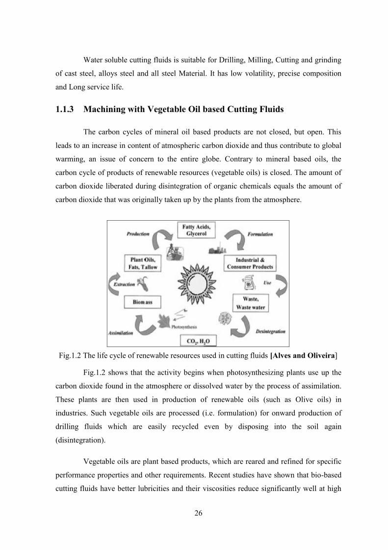
The carbon cycles of mineral oil based products are not closed, but open. This
leads to an increase in content of atmospheric carbon dioxide and thus contribute to global
warming, an issue of concern to the entire globe. Contrary to mineral based oils, the
carbon cycle of products of renewable resources (vegetable oils) is closed. The amount of
carbon dioxide liberated during disintegration of organic chemicals equals the amount of
carbon dioxide that was originally taken up by the plants from the atmosphere.
Fig.1.2 The life cycle of renewable resources used in cutting fluids [Alves and Oliveira]
Fig.1.2 shows that the activity begins when photosynthesizing plants use up the
carbon dioxide found in the atmosphere or dissolved water by the process of assimilation.
These plants are then used in production of renewable oils (such as Olive oils) in
industries. Such vegetable oils are processed (i.e. formulation) for onward production of
drilling fluids which are easily recycled even by disposing into the soil again
(disintegration).
Vegetable oils are plant based products, which are reared and refined for specific
performance properties and other requirements. Recent studies have shown that bio-based
cutting fluids have better lubricities and their viscosities reduce significantly well at high

27
temperature than the mineral oil-based oils. Vegetable oils are being investigated to serve
as a possible replacement for non biodegradable mineral oils, which are currently being
used as base oil in cutting fluids during machining processes. Vegetable oil-based cutting
fluids have reduced overall volume of fluids used for lubrication due to their higher
viscosity compared to the mineral oils based fluids. Mineral oils are petroleum based
cutting fluids, which are easily obtainable in markets and are relatively excellent
lubricants, but their continuous usage in machining will pose environmental contamination
and health problems to operators. Table 1.1 and Table 1.2 show the physical properties and
features of various cutting fluids. Table 1.3 shows the chemical properties of various
cutting fluids.
Table 1.1 Physical properties of various cutting fluids Cutting Fluids
Lubrication performance
Outstanding anti-rust
performance
Comprehensive antibacterial
properties
Strong de-foaming properties
Excellent cleaning
permeability Soluble cutting fluids
Excellent, Effectively reduce the
tools wear and get a good work-piece
surface quality
Effectively reduce the rust of
machine and work-piece
Use for a long time with rare corruption
phenomenon
reduce poor cooling lubrication, environmental pollution and increased workload caused by foam problem
make the product's
performance of fully play
VG 68 cutting oil
Excellent, Effectively reduce the
tools wear and get a better work-piece
surface quality
Comparatively low
reduce the rust of machine and
work-piece
Use for a long time with rare corruption
phenomenon
reduce poor cooling
lubrication, comparatively
low environmental pollution and
small effect on workload caused by
Foam problem
make the product's
performance of fully play
Vegetable oil based cutting fluids
Excellent, Effectively reduce the
tools wear and get a better work-piece
surface quality
Comparatively low
reduce the rust of machine and
work-piece
Use for a long time with rare corruption
phenomenon
reduce poor cooling
lubrication, environmental
Friendly and no foam occurred
make the product's
performance of fully play

28
Table 1.2 Features of various cutting fluids Cutting Fluids Purity Environment Total Acid Number Metal Working Fluid
Soluble cutting fluids
Dilution Ratio 1:10
Reduced pollution
0.01 Tool life increase
VG 68 cutting oil
high Eco-friendly
less than 1 Tool life increase drastically
Vegetable oil based
cutting fluids
high Eco-friendly
low Tool life increase
Table 1.3 Properties of various cutting oil Cutting Oil Specific Gravity Density Viscosity Soluble oil 0.917 917 kg/m3 0.028 Pa.s VG-68 oil 0.870 870 kg/m3 0.068 Pa.s Olive oil 0.918 920 kg/m3 0.084 Pa.s
1.1.4 Drilling under Dry and MQL Condition
The drilling operations are carried out under dry cutting conditions in which this
technique is less effective when higher machining efficiency, better surface finish quality
and severe cutting conditions are required. The tool can be isolated from work piece by
introducing protective layer on tool face. The cast material in general grey C.I. are
particularly well suited for the dry machining due to short chips, low cutting temperature
and forces and lubricating effect of the embedded graphite. Problems like chips removal
and jamming occur in drilling. The high strength alloy steels AISI 4340 with HRC 32~35
are machined in dry condition by TiN coated HSS-E drill bit but HRC>50 is difficult to
machined by un-coated HSS drill bit.
In order to avoid the use of cutting fluids because of their harmful ecological and
health effects, machining in many cases is carried out without using any cutting fluid. This
is possible only at low cutting speeds and easily machinable materials. Generally, dry
machining is not suitable in cases where excellent surface finish and high dimensional
stability are required.
This is so because dry machining involves high temperature generation which
enhances the formation of built up layer. This built up layer due to its unstable nature

29
breaks and takes away a portion of tool material due to its high adhesive nature causing
tool wear. The broken segments when stick to the machined surface deteriorates the
surface finish. Thus, dry machining without any lubricating and cooling enhancement is
not preferred in general cases of machining.
The drilling operations are carried out with MQL application. There are two basic
types of MQL delivery systems: external spray and through-tool. The external spray
system consists of a coolant tank or reservoir which is connected with tubes fitted with one
or more nozzles.
The external spray system can be assembled near or on the machine and has
independently adjustable or to control the fluid flow rate for balancing coolant delivery. It
is inexpensive, portable, and suited for almost all machining operations. The advantages of
such systems are simplicity and low cost. They are suited to be retrofitted to existing
machines with high-pressure, through the tool coolant capability. They are easy to service;
no critical parts are located inside the spindle. The amount of lubrication that can be
supplied to the cutting zone and consequently affects the performance of the cutting
process.
1.1.5 Summary of the Review
In comparison to conventional cutting fluids to minimum quantity lubricants have
the advantage of an advanced thermal stability and lubricating capability. Because of this,
separation of, firstly, the drill and work piece and, secondly, the drill and chips inside the
flutes can be maintained for a longer period of time than is the case with conventional
coolants. The most common minimum quantity lubricants today are poly-glycols and
ester-oils, which have a good lubrication capability and low evaporation tendency, whereas
fatty alcohols exhibit an improved cooling capability due to their high evaporation
tendency. However, despite its advanced lubrication capability compared to conventional
flood cooling.

30
1.2 Objectives of the Present Work
The main objective of the present work is to make a experimental investigation on
the role of Minimum Quantity Lubricant (MQL) with different cutting fluids (soluble
cutting oil, VG68 cutting oil and vegetable oil) in drilling AISI-4340 steel using HSS drill
bit and overall benefits in respects of
(i) cooling capacity of the fluid
(ii) dimensional deviation of the hole
(iii) taper of the hole
(iv) surface roughness
(v) tool wear

31
Chapter-2
Experimental Investigations 2.1 Experimental Procedure and Conditions
Significant progress has been made in dry and semidry machining recently, and
minimum quantity lubrication (MQL) machining in particular has been accepted as a
successful semidry application because of its environmental friendly characteristics. The
aim of the present work is primarily to explore and evaluate the role of such MQL on
machinability characteristics of some commonly used tool-work combinations mainly in
terms of cutting temperature, chip forms, cutting forces, tool life and product quality,
which govern productivity, product quality and overall economy.
Minimum quantity lubrication (MQL) refers to the use of cutting fluids of only a
minute amount-typically of a flow rate of 50 to 500 ml/hour-which is about three to four
orders of magnitude lower than the amount commonly used in flood cooling condition,
where, for example, up to 10 liters of fluid can be dispensed per hour. However, the MQL
needs to supply at high pressure and impinging at high speed through the nozzle at the
cutting zone. Considering the conditions required for the present research work and
uninterrupted supply of MQL at constant pressure over a reasonably long cut; a MQL
applicator used in the present work is shown in Fig.2.1.
Considering common interest and time constraint, only TiN coated HSS drill bit
have been used for the present investigation. Wide scope will remain for further study on
MQL effect in drilling steel by TiN coated HSS bit and exotic materials by high
performance drill bit. The drilling tests have been carried out by drilling of AISI-4340 steel
on a drill machine (Sunlike Machinery RD-750 Radial Drilling Machine, 3.7 KW) by HSS
drill bit under both dry and MQL conditions.
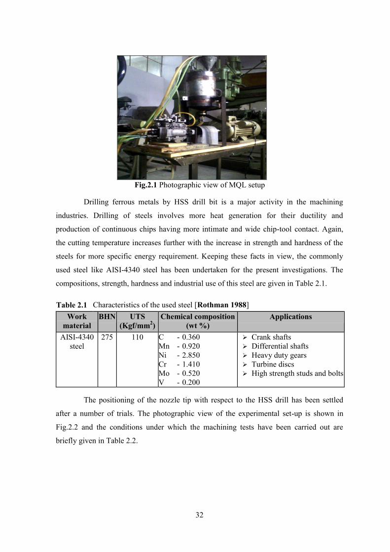
32
Fig.2.1 Photographic view of MQL setup
Drilling ferrous metals by HSS drill bit is a major activity in the machining
industries. Drilling of steels involves more heat generation for their ductility and
production of continuous chips having more intimate and wide chip-tool contact. Again,
the cutting temperature increases further with the increase in strength and hardness of the
steels for more specific energy requirement. Keeping these facts in view, the commonly
used steel like AISI-4340 steel has been undertaken for the present investigations. The
compositions, strength, hardness and industrial use of this steel are given in Table 2.1.
Table 2.1 Characteristics of the used steel [Rothman 1988] Work
material BHN UTS
(Kgf/mm2) Chemical composition
(wt %) Applications
AISI-4340 steel
275 110 C - 0.360 Mn - 0.920 Ni - 2.850 Cr - 1.410 Mo - 0.520 V - 0.200
Crank shafts Differential shafts Heavy duty gears Turbine discs High strength studs and bolts
The positioning of the nozzle tip with respect to the HSS drill has been settled
after a number of trials. The photographic view of the experimental set-up is shown in
Fig.2.2 and the conditions under which the machining tests have been carried out are
briefly given in Table 2.2.

33
Fig.2.2 Photographic view of the experimental set-up
Table-2.2 Experimental conditions
Machine tool : Sunlike Machinery RD-750 Radial Drilling Machine
Work material : AISI-4340 steel (228 mm x 102 mm x 16.40 mm)
Cutting tool : TiN coated HSS (Φ=8 mm)
Process parameters
Cutting velocity, Vc : 11.435 m/min
Feed rate, So : 0.09 mm/rev
Depth of cut, t : 16.00 mm
Flow rate : 100 ml/hr
Environment : Dry MQL with soluble oil MQL with VG 68 cutting oil MQL with olive oil
The cooling capacity of the cutting oil (soluble oil, VG 68 cutting oil and olive
oil) used in this experiment is important has been measured using a Muffle furnace. The
maximum temperature measured in the middle of the work piece was 400°C, obtained
after keeping it inside the furnace for a period of 7.0 minutes. After heating, the work
pieces were submitted to cooling condition similar to the experiments. The temperature
was measured by a K-type (Cromel-Alumel) thermocouple for about 7.0 minutes. This
thermo-sensor was connected to the work piece through a hole that allowed it to reach the

34
center of the work piece. The cutting fluid was injected at a distance of 15 mm from the
upper part of the work piece. The cooling capacity of the different cutting fluids is shown
in Fig. 2.3. From Fig.2.3, it is evident that the cooling capacity of VG68 cutting oil is more
in compare to other cutting fluids.
Fig. 2.3 Cooling capacity of the air and cutting fluids used in the experiments
2.2 Experimental Results
2.2.1 Number of Hole
The specimen was shaped by turning and facing in traditional lathe machine. Both
surfaces were finished by using surface grinding machine; Punching has been done on the
top surface of the specimen in right way in order to locate the drill bit at right place.
Punching was done on the specimen maintaining equal distance in between centres. The
work-piece was placed on the table of the drill machine and clamped very rigidly. A
hollow cylinder was placed keeping the work piece at its centre, whose sole purpose was
to control chips and coolant flow. Drill bit was placed on the top surface of the located
work-piece and holes were drilled sequentially (like 1, 2, 3, 4…….) under dry and MQL
condition.The photographic view of the holes is shown in Fig.2.4.
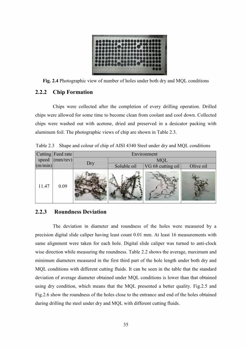
35
Fig. 2.4 Photographic view of number of holes under both dry and MQL conditions
2.2.2 Chip Formation
Chips were collected after the completion of every drilling operation. Drilled
chips were allowed for some time to become clean from coolant and cool down. Collected
chips were washed out with acetone, dried and preserved in a desicator packing with
aluminum foil. The photographic views of chip are shown in Table 2.3.
Table 2.3 Shape and colour of chip of AISI 4340 Steel under dry and MQL conditions
Cutting speed
(m/min)
Feed rate (mm/rev)
Environment
Dry MQL Soluble oil VG 68 cutting oil Olive oil
11.47 0.09
2.2.3 Roundness Deviation
The deviation in diameter and roundness of the holes were measured by a
precision digital slide caliper having least count 0.01 mm. At least 16 measurements with
same alignment were taken for each hole. Digital slide caliper was turned to anti-clock
wise direction while measuring the roundness. Table 2.2 shows the average, maximum and
minimum diameters measured in the first third part of the hole length under both dry and
MQL conditions with different cutting fluids. It can be seen in the table that the standard
deviation of average diameter obtained under MQL conditions is lower than that obtained
using dry condition, which means that the MQL presented a better quality. Fig.2.5 and
Fig.2.6 show the roundness of the holes close to the entrance and end of the holes obtained
during drilling the steel under dry and MQL with different cutting fluids.
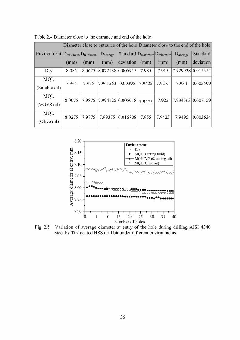
36
Table 2.4 Diameter close to the entrance and end of the hole
Environment
Diameter close to entrance of the hole Diameter close to the end of the hole
Dmaximum
(mm)
Dminimum
(mm)
Daverage
(mm)
Standard
deviation
Dmaximum
(mm)
Dminimum
(mm)
Daverage
(mm)
Standard
deviation
Dry 8.085 8.0625 8.072188 0.006915 7.985 7.915 7.929938 0.015354
MQL
(Soluble oil) 7.965 7.955 7.961563 0.00395 7.9425 7.9275 7.934 0.005599
MQL
(VG 68 oil) 8.0075 7.9875 7.994125 0.005018 7.9575 7.925 7.934563 0.007159
MQL
(Olive oil) 8.0275 7.9775 7.99375 0.016708 7.955 7.9425 7.9495 0.003634
0 5 10 15 20 25 30 35 407.90
7.95
8.00
8.05
8.10
8.15
8.20
Ave
rage
dia
met
er a
t ent
ry, m
m
Number of holes
Environment Dry MQL (Cutting fluid) MQL (VG 68 cutting oil) MQL (Olive oil)
Fig. 2.5 Variation of average diameter at entry of the hole during drilling AISI 4340
steel by TiN coated HSS drill bit under different environments

37
0 5 10 15 20 25 30 35 407.90
7.92
7.94
7.96
7.98
8.00
Ave
rage
dia
met
er a
t exi
t, m
m
Number of holes
Environment Dry MQL (Cutting fluid) MQL (VG 68 cutting oil) MQL (Olive oil)
Fig. 2.6 Variation of average diameter at exit of the hole during drilling AISI 4340 steel
by TiN coated HSS drill bit under different environments
2.2.4 Diameter Deviation or Taper
Fig.2.7 and Fig.2.8 show the taperness and diameter deviation under dry and
MQL with different cutting fluids condition. The average taper values and their dispersion
were smaller under MQL condition. Moreover, in both conditions the average taper values
were positive, i.e., the diameters in the entrance of the holes were bigger than at the end.
These bad results found for the holes made under dry condition are due lack of lubrication
action, which made the diameter in the beginning of the holes to increase.
0 5 10 15 20 25 30 35 400.00
0.05
0.10
0.15
0.20
0.25
0.30
Tape
rnes
s of t
he h
ole
Number of holes
Environment Dry MQL (Cutting fluid) MQL (VG 68 cutting oil) MQL (Olive oil)
Fig. 2.7 Variation of taperness of the hole during drilling AISI 4340 steel by TiN coated
HSS drill bit under different environments

38
0 5 10 15 20 25 30 35 400.00
0.05
0.10
0.15
Dev
iatio
n of
the h
ole,
mm
Number of holes
Environment Dry MQL (Cutting fluid) MQL (VG 68 cutting oil) MQL (Olive oil)
Fig. 2.8 Variation of deviation of the hole during drilling AISI 4340 steel by TiN coated
HSS drill bit under different environments
2.2.5 Surface Roughness
The variations of surface roughness for various machining conditions at constant
feed rate, spindle speed are shown below in Fig.2.9. The surface roughness values
decreases with the consecutive changes of cutting conditions. It is clearly shown that for
all cutting conditions, the surface roughness values obtained using MQL with olive is less
than other machining conditions. This is due to low viscosity with better lubricating effects
between work-piece and tool interface. It facilitates to reduce build-up-edge formation.
The surface finish is good for using olive oil MQL fluid application with compared to
soluble oil and VG-68 MQL application fluid.
0 5 10 15 20 25 30 35 400
1
2
3
4
5
6
7
8
9
10
Surfa
ce ro
ughn
ess o
f the
hol
e,
m
Number of holes
Environment Dry MQL (Cutting fluid) MQL (VG 68 cutting oil) MQL (Olive oil)
Fig. 2.9 Variation of surface roughness of the hole during drilling AISI 4340 steel by
TiN coated HSS drill bit under different environments
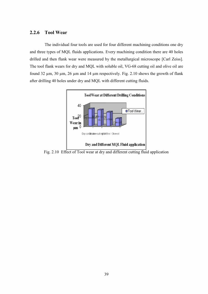
39
2.2.6 Tool Wear
The individual four tools are used for four different machining conditions one dry
and three types of MQL fluids applications. Every machining condition there are 40 holes
drilled and then flank wear were measured by the metallurgical microscope [Carl Zeiss].
The tool flank wears for dry and MQL with soluble oil, VG-68 cutting oil and olive oil are
found 32 µm, 30 µm, 26 µm and 14 µm respectively. Fig. 2.10 shows the growth of flank
after drilling 40 holes under dry and MQL with different cutting fluids.
Fig. 2.10 Effect of Tool wear at dry and different cutting fluid application
40
Chapter-3
Discussion on Experimental Results 3.1 Number of Hole
Number of hole in drilling operation is a major concern. Small number of holes
drilled by one bit increases the manufacturing cost due to tooling cost and cost for
replacement of the tool. Maximum possible numbers of drilled holes with a single piece of
bit are the prime necessity for high production manufacturing. During drilling huge
amount of heat is produced due to shearing of metal, friction between chips and flute and
rubbing the flank with newly cleaved surface. Machining with higher speed flank of drill
bit wears out, drill bit tip burns and melts by higher temperature produced in the cutting
zone. Dhar et al. 2004 found that in dry condition, for AISI-1060 steel, after completing 10
holes carbide drill bit was too worn out to do further operations impossible. For this
wearing tendency due to lot of heat sometimes drill bit break down within a short time.
AISI-4340 steel was drilled under dry and MQL with different cutting fluids
condition by 8 mm HSS drill bit is shown in Fig. 2.4. In dry condition drill bit becomes
burnt blue in color after completing 40 holes on AISI-4340 steel and creates very rough
surface with changed roundness. Very small chips are found on the surface of the hole as
wielded matter due to accumulation of huge heat while cutting. On the other hand in MQL
with different cutting fluids condition drill bit remains its original color and without any
burning holes metallic color chips are shown in Table 2.1. Holes dimension are very close
to acceptable limit having proper shape and no wielded chip is found in the MQL drill.
3.2 Chip Formation
The chip formations are investigated to drill AISI 4340 steel using titanium
nitride coated drill bit under dry and MQL with different cutting fluids conditions with a
spindle speed of 455 rpm and feed rate of 0.09 mm/rev. The surface roughness of a drilled
41
surface depends on the nature of chip removal from the cutting zone. The chip formation
examination would give a clear view of the machining parameter influencing the tool wear
and surface roughness. During the drilling process, chips were collected and examined for
general characteristics. On observing the nature of chip formation, chips are short and no
curls material is formed. This makes the chips disposal easier from the machined surface;
the hard AISI 4340 alloy steel particles and soft graphite particles act as regions of crack
propagation, and hence act as effective chip breakers.
In this study, the performances of olive oil, mineral oil-based cutting fluid and
soluble oil were compared with dry condition during machining AISI 4340 steel. The chip
formation rates of the work-piece using olive oil as vegetable oils as cutting fluids under
cutting speed (455 rev / min) and feed rate (0.09 mm/rev) were compared with that of
mineral oil VG-68, soluble oil and dry machining. The average chip thickness of dry
machining conditions is 0.39175 mm, where the average chip thickness of conventional oil
(i.e. soluble oil) is 0.33825 mm which is less than that of dry machining. Olive oil gives the
overall lowest chip thickness of 0.20075 mm due to its better lubricating property with low
viscosity. This is followed by that of the VG-68 oil and the conventional oil (i.e. soluble
oil) as compared with dry machining of mm thickness. Fine surface morphology indicates
improved surface roughness compared to using other cutting fluids. Based on these results,
Olive oil is being recommended as viable alternative lubricants to the mineral oil during
machining AISI 4340 steel.
3.3 Roundness Deviation
Before the analysis of the quality parameters of the holes, it is important to note
that neither diameter nor any other quality parameter of the hole was influenced by tool
wear. It can be seen in Table 2.4 that the standard deviation of the average diameter
obtained under MQL condition is lower than that obtained using dry condition, which
means that the MQL presented a batter quality with presence of proper lubrication at the
chip-tool interface.
Fig.2.5 shows the roundness of the holes close to the entrance and Fig. 2.5 shows
the roundness of the holes close to the end of AISI-4340 steel. This result can be attributed
to the lower cutting force and the shorter diameters. In dry condition due to excessive

42
heating, scarcity of coolant and lubricant, rubbing the tool face with work material and
commencement of tool wear, the deviation is very large. Fig.2.5 shows the roundness of
the holes close to the entrance and Fig. 2.6 shows the roundness of the holes close to the
end of the holes obtained during drilling AISI-4340 steel and it can be seen from these
figures show that the roundness deviation has a little change from the beginning to the end
of the holes under MQL application with compare to dry condition, this result can be
attributed to the lower cutting force and smaller roundness deviation due to effective
lubrication. The roundness deviation is not uniform and steady in AISI-4340 steel as
shown in Fig. 2.5 and Fig. 2.6, because of high hardness due to high alloying elements.
The roundness deviation was smaller at both the entrance and end of the holes under HPC
condition in compare to dry condition for both the steel, because of high lubricant
capacity.
3.4 Diameter Deviation or Taper
From the above Fig.2.7 shows the diameter deviation under dry and MQL with
different cutting fluid conditions. The diameter deviations of holes using MQL (Cutting
fluids i.e. soluble oil) are low with compare to dry and other two types of cutting fluids
application and the diameter deviations of holes using MQL (Cutting fluids i.e. olive oil)
are low compare to dry and VG-68 cutting fluids application. This is also followed by that
of the VG-68 cutting oil as compared with dry machining condition. Thus, the diameter
deviation values would become smaller under MQL condition with compare to dry
machining condition.
From the above Fig. 2.7, The Taperness of hole of the work-piece using Olive oil
as vegetable oils based cutting fluids under cutting speed (455 rev / min) and feed rate
(0.09 mm/rev) were compared with that of mineral oil VG-68, soluble oil and dry
machining. In drilling operation at MQL (cutting oil i.e. soluble oil) environment, the
taperness of holes are low with compare to dry and other different cutting fluids
application. This is also followed by that of the VG-68 oil and the olive oil as compared
with dry machining condition. The Results are shown that the drilling operations at dry
machining environment, the taperness of holes are found high with compare to different
cutting fluids application. Thus the Soluble oil gives the overall lowest taperness of holes.

43
3.5 Surface Roughness
The variations of surface roughness values for various machining conditions at
constant feed rate, spindle speed are shown in Fig. 2.9. From Fig. 2.9, the surface
roughness values decreases with the consecutive changes of cutting conditions. It is clearly
shown that for all the cutting conditions, the surface roughness values obtained using Olive
oil as vegetable oil based MQL application fluid is less than other dry, soluble oil and VG-
68 MQL fluid applications. This is due to low viscosity with better lubricating effects
between work-piece and tool interface. It facilitates to reduce build-up-edge formation.
The surface finish is good for using olive oil MQL fluid application with compared to
soluble oil and VG-68 MQL application fluid. Hence, usage of olive oil is advantageous in
applications that require good surface finish.
3.6 Tool wear
The individual four tools are used for four different Machining conditions one dry
and three types of MQL fluids applications. Every Machining conditions there are 40 holes
drilled and then Flank wears are measured by the metallurgical Microscope. The tool flank
wears for dry and MQL with soluble oil, VG-68 cutting oil and olive oil are found 32 µm,
30 µm, 26 µm and 14 µm respectively. Fig. 2.10 shows the growth of flank after drilling
40 holes under dry and MQL with different cutting fluids. The Results are shown that the
drilling operation at dry machining environment, tool wears is high compare to different
cutting fluids application. Drilling operation at MQL (using olive oil) environment, tool
wears is low compare to dry and other different cutting fluids application.
44
Conclusions
The main objectives of the present investigation are to compare the performance
of drilling AISI 4340 steel by TiN coated twist drill bit in terms of number of holes, chip
formation, roundness deviation, diameter deviation or taper and surface roughness by
under different cutting conditions (dry and MQL with different cutting fluids). The effect
MQL with different cutting fluids on flank wear of drill bit has also been presented in this
study.
The number of hole drilled under MQL with different cutting fluids condition is
much higher in compared to dry condition. But the number of hole drilled is more
when drill under MQL with olive oil in compare to other cutting fluids. It indicates
that the MQL with olive oil is more effective than other cutting fluids.
The chips thickness formed using MQL with olive oil as cutting fluid was lowest,
probably due to its better lubricating ability. This allows easier and deeper
penetration of cutting tool into work piece and better metal removal rate.
Due to excessive heating, scarcity of coolant and lubricant, rubbing the tool face
with work material and commencement of tool wear, in dry condition the
roundness deviation is very large where the roundness deviation is very low while
drilling under MQL with different cutting fluids. But the roundness deviations are
found very low while drilling under MQL with using soluble oil.
The diameter deviation values would become smaller under MQL condition with
compare to dry machining condition.
The surface roughness in machining with olive oil sample gave competitive result
of finest and smoothest view as compared with mineral oil-based VG-68 oil,

45
soluble oil sample and dry condition machining, which is an indication of good
surface roughness. Better surface finish shows that there is lesser friction and wear
between tool and work-piece
The flank wear under dry and MQL with soluble oil, VG-68 cutting oil and olive
oil are found 32 µm, 30 µm, 26 µm and 14 µm respectively. The tool wears is
found to be low while drilling under MQL with olive oil compare to dry and other
different cutting fluids application.

46
References
Ackroyd, B., Compton, W.D. and Chandrasekhar, S., “Reducing the need for cutting fluids
in drilling by means of modulation-assisted drilling”, Proc. of the International
Mechanical Engineering Congress and Exposition, Vol. 8, pp. 405–411, 1998
Attanasio, A., Gelfi, M., Giardini, C. and Remino, C., “Minimum quantity lubrication in
turning wear”, Vol. 260, pp. 333-338, 2006
Autret, R. and Liang, Y., “Minimum Quantity Lubrication in Finish Hard Turning”,
Master’s Thesis, Georgia Institute of Technology, Atlanta, Georgia, USA. 2003
Baradie, M.A.E., “Cutting Fluids, Part II: Recycling and clean machining”, Journal
of Materials Processing Technology, Vol. 56 pp. 798-806, 1996
Baradie, M.A.E., “Cutting Fluids, Part I: Characterisation”, Journal of Materials
Processing Technology, Vol. 56 pp. 786-797, 1996
Barrow, G., “Wear of cutting tools”, Tribology-1, pp. 22–30, 1972
Bartz, W.J., “Ecological and environmental aspects of cutting fluids”, Lubrication
Engineering, Vol. 57, pp. 13-16, 2001
Beaubien, S.J. and Cattaneo A.G., “A study of the Role of Cutting Fluid in Machining
Operating”, Lubrication Engineering, Vol. 10, pp. 74-79, 1964
Boelkins, C.U., “Cutting Tool Engineering”, Vol. 3, pp. 71-75, 2009
47
Bono, M. and Jun, N.,“The Location of the Maximum Temperature on the Cutting Edges of
a Drill”, International Journal of Machine Tools and Manufacture, Vol. 46, pp. 901-
907, 2006
Boubekri, N. and Shaikh, V., “Machining Using Minimum Quantity Lubrication”, A
Technology for Sustainability, International Journal of Applied Science and
Technology Vol. 2, No. 1, 2012
Braga, D.U., Diniz, A.E., Miranda, G.W.A. and Coppini, N.L., “Using a Minimum
Quantity of Lubricant and a Diamond Coated Tool in the Drilling of Aluminum-
Silicon Alloys”, Journal of Materials Processing and Technology, Vol. 122, pp. 127-
138, 2002
Briant, C.L., Banerji, S.K. “Tempered martensite embrittlement in phosphorus doped
steels”, Metal. Trans., Vol. 10A, 1729–1739, 1979
Brinksmeier, E., Walter, A., Janssen, R. and Diersen, P., “Aspects of cooling lubrication
reduction in machining advanced materials”, Proceedings of the Institution of
Mechanical Engineers, Journal of Engineering Manufacture, pp. 769-778, 1999.
Callister, W.D., “An Introduction to Material Science and Engineering”, 3rd edition,
Wiley, New York, 1994
Carlson, M.F., Narasimha, B.V. and Thomas, G., “The effect of austenitizing temperature
upon the microstructure and mechanical properties of experimental Fe:Cr:C steel”,
Metall. Trans. Vol. 10A, pp. 1273–1281, 1989
Cassin, C. and Boothroyed, G.,“Lubrication Action of Cutting Fluid”, Journal of
Mechanical Engineering Science, Vol. 7, pp. 67-81, 1965.
Chai, M.F. and Laird, C.,“Mechanisms of cyclic softening and cyclic creep in low carbon
steel”, Mater. Sci. Eng. Vol. 93, pp. 159–174, 1987
Davies, M. A., Chou, Y. and Evans, C. J., “On Chip Morphology, Tool Wear and Cutting
Mechanics Hardened Steels”, Annals of CIRP, Vol. 45/1, pp. 77-82, 1996

48
DeGarmo, E.P., Black, J.T., Kosher, R.A., “Materials and Processes in Manufacturing”,
Maxwell MacMillan Publication, 7th Edition, New York, USA, pp. 578-581, 1984
Derflinger, V., Bra¨ndle, H. and Zimmermann, H., “New hard/lubricant coating for dry
machining”, Surface Coating Technology, Vol. 113, pp. 286–292, 1999
Dhar, N. R , Rahman K. M , Islam, S. and Hossain, M., “Using a minimum quantity of
lubricant (MQL) and a carbide tool in the drilling of AISI-1060 steel”, Journal of
Mechanical Engineering, IEB, Vol. ME 33, pp. 22- 31, 2004
Dhar, N. R., et al. “An experimental investigation on effect of minimum quantity
lubrication in machining AISI 1040 steel”, International Journal of Machine tools
and Manufacture, Vol. 47, pp. 748-753, 2007.
Dhar, N. R., et al. “Effect of minimum quantity lubrication (MQL) on tool wear and
surface roughness in turning AISI-4340 steel”, Journal of Materials Processing
Technology, Vol. 172, pp. 299-304, 2006
Dhar, N. R., et al. “The influence of minimum quantity lubrication (MQL) on cutting
temperature, chip and dimensional accuracy in turning AISI-1040 steel”, Journal of
Materials Processing Technology, Vol. 171, pp. 93-99, 2006.
Donaldson, C., Le Cain, G.H. and Gould, V.C., “Tool design”, McGraw Hill, New York,
1973
Durval, U.B., Anselmo, E.D., Gilberto, W.A.M. and Nivaldo L.C., “Using a minimum
quantity of lubricant (MQL) and a diamond Coated tool in the drilling of aluminum–
silicon alloys”, Journal of Materials Processing Technology, Vol. 122, pp. 127–138,
2002
Eyup, B. and Babur O., “Investigation of the effect of drilling conditions on the twist drill
temperature during step-by-step and continuous dry drilling”, Materials and Design,
vol. 27; pp. 446–454, 2006
49
Eyup, B. and Babur, O., “Finite element and experimental investigation of temperature
changes on a twist drill in sequential dry drilling”, International Journal Advance
Manufacturing Technology, Vol. 28, pp. 680–687, 2006
Ezugwu, E.O. and Lai C.J., “Failure Modes and Wear Mechanisms of M35 High Speed
Steel Drills when Machining Inconel 901”, Journal of Mat. Processing Tech., Vol.
49, pp. 295-312, 1995
Ezugwu, E.O. and Bonney, J. “Effect of High-pressure Coolant Supplies when Machining
Nickel-base Inconel 718, Alloy with Ceramic Tools”, STLE, 2003
Ezugwu, E.O. and Lai, C.J., “Failure Modes and Wear Mechanisms of M35 High Speed
Steel Drills when Machining Inconel 901”, Journal of materials Processing
Technology, Vol. 49, pp. 295-312, 1995
Ezugwu, E.O.,“High speed machining of aero-engine alloys”, Journal of the Brazil Society
of Mechanical Science and Engineering. Vol. 26, No. 1/11, 2004
Klocke, F. and Eisennbla¨tter, G., “Dry Cutting”, Annals of the CIRP Vol. 46/2, pp. 519-
526, 1997.
Filipovic, A. and Stephenson, D.A., “Minimum Quantity Lubrication (MQL) Applications
in Automotive Power-Train Machining”, Machining Science and Technology, Vol.
10, pp. 3-22, 2006
Frederick, M. “Benefits of high-pressure coolant”, Machine Shop Guide Web Archive,
2001
Galloway, D.F., “Some experiments on the influence of various factors on drill
performance”, Trans. A.S.M.E., Vol. 79, pp. 191-231, 1957
Glenn, T.F. and Antwerpen, F.V., “Opportunities and market trends in metalworking
fluids”, Lubrication Engineering, Vol. 54, pp. 31-37, 1998
Gregory, S.A., “The pressure’s on to improve Drilling”, Vol. 51, No. 1, 1999
50
Haan, D.M., Batzer, S.A., Olson, W.W. and Sutherland, J.W., “An experimental study of
cutting fluid effects in drilling”, Journal of Materials Processing Technology, Vol.71
pp. 305–313, 1997
Heinemann, R., “Improving the Performance of Small Diameter Twist Drills in Deep-Hole
Drilling”, PhD-Thesis, UMIST, 2004
Heisel, U. and Lutz, M., “Pesquisa de fluido de refrigeração e de lubrificação, Máquinas e
Metais”, Vol. 388, pp. 40-49, 1998
Hidetaka, K., and Hideyo, T., “Drilling of a Small and Deep Hole Using a Twist Drill”,
The Japan Society of Mechanical Engineers, Vol. 62, pp. 3691-3697, 1996
Hong, S.Y., Ding, Y. and Jeong, W., “Friction and cutting forces in cryogenic machining
of Ti-6Al-4V”, International Journal of Machine Tools and Manufacture, Vol. 41, pp.
2271-2285, 2001
Horn, R.M. and Ritchi, R.O., “Mechanisms of tempered martensite embrittlement in low
alloy steel”, Metal. Trans. Vol. 9/A, pp. 1039–1047, 1978
Huang, D.H. and Thomas, G., “Structure and mechanical properties of tempered
martensite and lower bainite in Fe-Ni-Mn-C steels”, Metal. Trans. Vol. 2A, pp.
1587–1596, 1971
Irvine, K.J., “The development of high-strength steels”, J. Iron Steel Inst. Vol. 12 pp. 620–
629, 1962
Jeff, A.D., Richard, E.D. and Shiv, G. K., “Generalized Groove-type Chip Breaker Effects
on Drilling for Different Drill Diameters and Flute Shapes”, International Journal of
Machine Tools and Manufacture, Vol. 45, pp.1588–1597, 2005
Kang, D.C., “Geometry analysis and CAD/CAM Software for twist drills”, Ph.D. Thesis,
The University of Melbourne, 1997
51
Kitagawa T., Kubo, A. and Maekawa, K., “Temperature and Wear of Cutting Tools in
High Speed Machining of Inconel 718 and Ti-6V-2Sn”, Wear, Vol. 202, pp. 142-148
1997
Kubota, H. and Tabei, H., “Drilling of a small and deep hole using a twist drill,
Transactions of the Japan Society of Mechanical Engineers”, Part C, 62/601, pp.
3691–3697, 1999
Kwon, H., Cha, J.C., Kim, C.H., “The effect of grain size on fracture behavior in tempered
martensite embrittlement for AISI 4340 steel”, Mater. Sci. Eng. Vol. 10, pp. 121–
128, 1988
Machado, A.R. and Wallbank, J., “The Effect of Extremely Low Lubricant Volumes in
Machining Wear”, Vol. 210, pp. 76-82, 1997
MaClure, T.F., Adams, R., Gugger, M.D. and Gressel, M.G., “Comparison of Flood vs.
Microlubrication on Machining Performance”, 2007
Obikawaa, T., et al., “High-speed grooving with applying MQL”, International Journal of
Machine Tools and Manufacturer, Vol. 46, pp. 1854-1861, 2006
Popke, H., Emmer, Th. and Steffenhagen J., “Environmentally clean metal cutting
process-Machining on the way to dry machining”, Proceedings of the
Institution of Mechanical Engineers, Part B, Journal of Engineering Manufacture,
pp. 329-332, 1999
Quaile, R., et al., “Understanding MQL Machining with minimum quantity lubricant can
save money and improve both tool life and part finish”, Modern Machine Shop, 2011
Sahu, S.K., et al. “Effect of groove-type chip breakers on twist drill performance”,
International Journal of Machine Tools and Manufacture, Vol. 43, pp. 617–627,
2003
Salete, M.A., et al., “Vegetable based cutting fluid- An environmental alternative to
grinding process”. Proceedings at 15th CIRP International Conference on Life Cycle
Engineering, Brazil, 2008
52
Shaw, M.C., “Metal Cutting Principles”, Clarendon Press, Oxford, England, pp. 292-332,
1991
Shimizu, K. and Nishiyama, Z., “Electron microscopic studies of martensitic
transformation in iron alloys and steels”, Metal. Trans, Vol. 3A, pp. 1055–1066,
1972
Silva, M.B.D., and Wallbank, J., “Lubrication and application method in machining,
Lubrication and Tribology”, Vol. 50, pp. 149-152, 1998
Sokovic, M. and Mijanovic, K., “Ecological aspects of the cutting fluids and its influence
on quantifiable parameters of the cutting processes”, Journal of Materials
Processing Technology, Vol. 109, pp. 181-189, 2001
Sreejith, P.S., and Ngoi, B.K.A., “Dry machining; Machining of the future”, Journal of
Materials Processing Technology, Vol. 101, pp. 287-291, 2000
Strenkowski, J.S., Hsieh, C.C. and Shih, A.J., “An analytical finite element technique for
predicting thrust force and torque in drilling”, International Journal of Machine
Tools and Manufacture, Vol. 44, , pp. 1413-1421, 2004
Tejasmaru, B.E. “Effects of minimum quantity lubrication (MQL) on tool life in drilling
AISI 1018 steel”. Master of Science (Engineering Systems-Mechanical Systems), pp.
73, 2012
Tous, J. and Ferguson, L., “Mediterranean fruits”, pp. 416-430, 1996
Wakabayashi, T., Inasaki, I., Suda, S., and Yokota, H., “Tribologial Characteristics and
Cutting Performance of Lubricant Esters for Semi-Dry Machining”. CIRP Annals,
Vol. 51 No.1, pp. 61–64, 2003
Wakabayashi,T., Inasaki, I. and Suda, S., “Tribological Action and Optimal Performance
Research Activities Regarding MQL Machining Fluids”, Machining Science and
Technology, Vol. 10, pp. 59-85, 2003


