Cover Page
Facilities Standards
Manual
As amended through
January 1, 2020

Index of Loudoun County Facilities Standards Manual Amendments (Since 2000)
* Enforcement of the Virginia Stormwater Management Handbook was deferred 120 days to enable the County
to hire the staff resources and conduct the training necessary to successfully implement the new regulations.
Application
Number
Title Chapters Amended Adoption
Date
Effective
Date
DOAM-2018-0001 Buffer and Landscaping
Amendments Chapters 7 & 8 11/21/19 1/1/20
DOAM-2018-0002
FSM Amendments
(Emergency Vehicle
Preemption, Fire Apparatus
Access Roads, Driveway
Detail, LDIA bonds)
Chapters 4 & 8 10/17/19 10/18/19
DOAM-2017-0001
FSM Amendments (Trees,
Archaeology, Steep Slopes
& Bonding)
Chapters 7 & 8 12/13/17 1/15/18
DOAM-2016-0002 Floodplain and Bonding Chapters 5, 7 & 8 10/12/16 11/1/16
DOAM-2012-0003 Phase 3 Amendments Chapters 4, 6, 7 & 8 2/11/15 4/1/15
DOAM-2013-0002 Stormwater Amendments Chapters 1 & 5 5/21/14 7/1/14
DOAM-2012-0002 Phase 2 Amendments Chapters 2, 3, 4, 5, 6 & 8 5/8/13 7/1/13
DOAM-2012-0001 Phase 1 Amendments Chapters 6, 7 & 8 10/3/12 11/1/12
DOAM-2010-0001 FSM Amendments Chapters 4, 7 & 8 11/8/10 11/8/10
DOAM-2009-0002 Limestone Overlay District Chapters 6 & 8 & LSDO 2/17/10 2/17/10
DOAM-2009-0001 FSM Amendments Chapters 4, 5, 6 & 8 11/9/09 11/9/09
DOAM-2007-0002 FSM Amendments Chapters 2, 4, 5, 6, 7 & 8 12/4/07 12/4/07
DOAM-2007-0001 Rural Addition Program LSDO 7/10/07 7/10/07
DOAM-2005-0003 Western Loudoun Zoning Chapters 4 & 8 & LSDO 12/5/06 12/5/06
DOAM-2004-0001 FSM/LSDO Amendments Chapters 4, 5, 7, 8, LSDO 6/16/05 7/1/05
DOAM-2002-0001 FSM Amendments Chapters 2, 4, 5, 6, 7 & 8 6/17/02 7/1/02*
DOAM-2000-0001 LSDO Administrative Items LSDO 4/29/2000 4/29/2000
Additional information pertaining to the approved DOAMs, including redline
text of the amendments, is available in the Board Meeting Documents folder by
adoption date: http://www.loudoun.gov/index.aspx?NID=3426


Loudoun County Facilities Standards Manual Primary Table of Contents
___________________________________________________________________________
Chapter 1 Authority
Chapter 2 Water Supply and Distribution Systems
Chapter 3 Waste Collection and Disposal Systems
Chapter 4 Transportation
Chapter 5 Water Resource Management
Chapter 6 Soils, Geotechnical, Geophysical and Hydrogeological
Studies
Chapter 7 Environmental Design Standards
Chapter 8 Administrative Procedures

CHAPTER 1.000
AUTHORITY
1.100 GENERAL
1.200 INTERPRETATION AND REVISION
1.300 NECESSARY REFERENCE MATERIAL

Section 1.100 – Authority - General
Effective Date: 07/01/2014
CHAPTER 1.000
AUTHORITY
1.100 GENERAL
This document, entitled the Loudoun County Facilities Standards Manual, has been
developed and designed to assist the public and the development community in
determining the policies, which apply to land development in the County. It contains
information primarily concerned with the design and construction standards and guidelines
for improvements related to subdivisions and site plans.
The majority of the information contained herein is a compilation of existing requirements
already in place. This document will serve as a central reference for these items.
Except as specified below, each land development application shall be subject to the
version of the Facilities Standards Manual in effect at the time of initial acceptance. Land
Development Applications for Record Plats, Dedication Plats, or Easement Plats shall be
subject to the version of the Facilities Standards Manual in effect at the time of the initial
submission and acceptance of the Construction Plans and Profiles or Site Plans upon such
plat is based.
A. Each land development application shall conform to the current stormwater
management technical criteria in Chapter 5 of this manual, unless subject to
9VAC25-870-47 or grandfathered in accordance with the Virginia Stormwater
Management Program (VSMP) grandfathering provisions of Chapter 1096 of the
Codified Ordinances (and 9VAC25-870-48). Land development applications that
are grandfathered shall meet the technical criteria of Part II.C (9VAC25-870-93
through 9VAC25-870-99), as well as the following requirements:
1. The land development application shall have been approved prior to July 1,
2012.
2. The land development application shall be a proffered plan of development,
Special Exception, Preliminary Plat of Subdivision, Record Plat,
Construction Plans and Profiles, or Site Plan. In addition, the following
land development applications have been determined by Loudoun County
as being the equivalent thereto: Rezoning, Rural Economy Site Plan,
Dedication Plat, Boundary Line Adjustment, Preliminary/Record
Subdivision, Family Subdivision, Subdivision Waiver/Low Density
Waiver, Easement and Vacation Plat, Dedication Plat, Plat and Plan
Revision, Site Plan Amendment, or any other application as approved by
the Director.
3. The land development application referenced in Subsection 1 and
Subsection 2 above shall have included a Layout. "Layout" means a
conceptual drawing sufficient to provide for the specified stormwater

Section 1.100 – Authority - General
Effective Date: 07/01/2014
management facilities required at the time of approval, as defined in 9VAC-
25-870-10.
4. The land development application has not been subsequently modified or
amended in a manner resulting in an increase in the amount of phosphorus
leaving each point of discharge, and such that there is no increase in the
volume or rate of runoff. In order to verify this condition, a comparison of
the layouts between the original land development application and the
modified version may be utilized. If the comparison of layouts is not
conclusive, a comparison of performance-based calculations found in the
technical criteria of Part II.C (9VAC25-870-10) as well as water quantity
engineering calculations shall be required.
5. Land development applications on parcels or lots which are part of a
residential, commercial, or industrial subdivision served by an approved
stormwater management facility designed to treat the said parcel or lot shall
be deemed grandfathered.
B. In the event any land development application is made for a development which is
served by or subject to a previously approved roadway, such previously approved
roadway would not have to be upgraded to meet current standards.
C. Any land development application proposing:
1. a site redevelopment involving major reconstruction or major demolition,
or
2. a revision or construction modification to alter stormwater management
facilities which (a) is in conjunction with a change to the land use on-site
that would result in an increase in runoff over that for which the facility was
originally designed or (b) benefits additional land areas not previously
utilizing the improvements included that results in an increase in runoff over
which the facility was originally designed, except when such changes are
minimal in nature with negligible impact.
shall be subject to the current version of this manual.

Section 1.200 – Interpretation and Revision
Effective Date: 07/01/2014
1.200 INTERPRETATION AND REVISION
A. Interpretation
These standards and guidelines are designed to supplement the provisions of
existing Federal and State regulations and County codes and ordinances. Nothing
herein shall be deemed to waive or modify other requirements of existing codes.
Except as expressly provided otherwise in this document, the Director of Building
and Development is the designated official charged with the administration of the
standards and requirements contained in this manual and, in administering them,
shall treat them as guidelines. The Director may allow for variations of given
standards where the effect of such variation is in keeping with established
engineering practices and procedures and shall make the final decision on all
questions regarding interpretation of this manual, after reviewing recommendations
from the designated departments, authorities, boards, and committees.
B. Revision
As new basic information on design criteria becomes available and is accepted, and
as Federal, State, and County laws, regulations, and standards are changed, they
will be reflected in this publication after at least an annual review. Any record
plats, final site plans or construction plans and profiles submitted prior to the
approval of any revisions will comply with the standards in effect at the time of the
officially accepted submission for such record plats, final site plans, and/or
construction plans and profiles.
C. Facilities Standards Manual Review Committee
This committee shall consist of at least seven representatives appointed by the
Board of Supervisors of Loudoun County. The candidates for appointment may be
any persons whom the Board of Supervisors deem qualified. In addition to public
notification and request for citizen participation on the Review Committee,
nominations shall be requested from, but not limited to the following organizations:
National Association of Industrial & Office Parks
Loudoun Chamber of Commerce
Virginia Society of Professional Engineers
Virginia Association of Surveyors
Heavy Construction Contractors Association
Associated Building Contractors
Northern Virginia Building Industry Association
Piedmont Environmental Council
Washington Area Council of Engineering Laboratories
Consulting Engineers Council
Association of Soil & Foundation Engineers
Association of Engineering Geologists
Virginia Association of Professional Soil Scientists

Section 1.200 – Interpretation and Revision
Effective Date: 07/01/2014
Virginia Association of Geologists
Loudoun County Board of Realtors
Engineers & Surveyors Institute
The majority of members shall be actively involved in the Loudoun County
Community and shall represent professionals registered to practice engineering,
surveying, geology, landscape, architecture, or soil science in Virginia.
Committee members shall elect a chairman. The Director of Building and
Development or his designee shall serve as secretary to the committee. County
staff members may serve as advisory staff to the committee but shall not be
appointed to sit on committee.
Members shall be appointed for a term of not less than one year and no more than
four years and shall serve until replaced. If a member resigns, the Board of
Supervisors will appoint a replacement.
The committee shall meet at least once a year to review the Facilities Standards
Manual and shall advise the Director of Building and Development of their findings
and recommendations. Whenever a change in the Facilities Standards Manual is
proposed, the Director of Building and Development shall request the advice of the
committee prior to requesting a public hearing for consideration of changes to the
FSM.
D. Appeals
Any applicant who is aggrieved by an interpretation or decision made by the
Director in the administration of the standards and requirements contained in this
manual may, within five (5) working days of receiving written notice of such
decision or interpretation, deliver a written notice to the Director requesting the
Chairman of the Facilities Standards Manual Review Committee (the Committee),
to appoint a subcommittee to review the matter. Such subcommittee shall consist
of at least three members of the Committee. Such subcommittee shall hear the
matter at the Department of Building and Development at a time convenient to the
applicant and the Director, but in no event more than thirty (30) days after the notice
and request is delivered to the Director, and shall make a written recommendation
to the Director, stating the basis for such recommendation.

Section 1.200 – Interpretation and Revision
Effective Date: 07/01/2014
Upon receiving such recommendation from the subcommittee, the Director shall
render a final decision within five (5) working days thereafter. If the applicant is
aggrieved by such final decision, the applicant may take such action as is otherwise
provided by law with respect to the subject land use application at the appropriate
time.
Any applicant who files an appeal under this subsection of the Facilities Standards
Manual shall waive, during the period of pendency of the appeal, any right to
require the County to take any action to approve or disapprove the application
pursuant to any statutory or other legally imposed timeline requirement. Any
applicant giving notice of such appeal shall execute and deliver to the said Director
such written waiver along with such notification in substantially the following
language:
"I/we hereby waive any right I/we may have to require the County to take any action
to approve or disapprove the subject application during the pendency of the appeal,
such that the time which elapses from the date of delivery of this notification to the
Director until the date of the final decision on this appeal by the Director shall not
be counted in determining the date as of which County action on the application is
legally required."
The thirty (30) day period for action on this appeal shall not commence until such
written waiver has been delivered to the Director.
E. Disclaimer of Liability
The purpose of this manual is to establish reasonable land development standards
and guidelines for the protection and promotion of the general health, safety, and
welfare of the County's residents. Approval of plans and plats by the County or its
agencies pursuant to the ordinance and this manual, is not intended and shall not be
deemed as a guarantee or warranty for any individual, landowner, or developer that
any improvements will be designed, planned, constructed, or operated in any
particular manner or be free from defects. Such approval shall create no duty or
result in any liability on the part of the County, its officials, or employees for any
claim, demand, suit, or damages alleged to have resulted from the development,
construction, existence, or operation of improvements constructed pursuant to such
approved plans or plats. Further, no such approval shall operate as or be deemed
as a waiver of any provision or requirement of the ordinance, or this manual, unless
such waiver has been specifically granted in writing by the Director as a variation
allowed under Section 1.200.A hereof. In the event that any aspect of any such
approved plan or plat fails to comply with any provision or requirement of this
ordinance, or this manual, in effect at the time of such approval, such provision or
requirement of the ordinance, or this manual, shall take precedence over the
approved plans, and development shall be in accordance with the ordinance and
this manual.
Section 1.300 – Necessary Reference Material
Effective Date: 07/01/2014
1.300 NECESSARY REFERENCE MATERIAL
In order to properly utilize this manual, the designer or user in general should have certain
publications readily available, as they are referenced throughout this document.
A listing of the most commonly utilized publications is as follows:
"The Sewage Handling and Disposal Regulations," Board of Health, Commonwealth of
Virginia.
"Virginia Water Works Regulations," State Health Department, Division of Water
Engineering.
"Virginia Erosion and Sediment Control Handbook."
The Loudoun County Sanitation Authority's Design and Construction Standards for
Sanitary Sewers and Water Supply System.
The Building Official's Code Administrators, "The BOCA Basic Building Code," latest
edition.
"Interpretive Guide to the Use of Soils Maps, Loudoun County, Virginia," latest edition.
Controlling Urban Runoff: A Practical Manual for Planning and Designing Urban BMPs.
Federal Manual for Identifying and Delineating Jurisdictional Wetlands.
Additional reference materials specific to each subject area are listed at the end of each
chapter.

CHAPTER 2.000
WATER SUPPLY AND DISTRIBUTION SYSTEMS
2.100 GENERAL
2.200 DESIGN AND CONSTRUCTION STANDARDS
2.201 LOCATION OF WATERMAINS IN REGARD TO PUBLIC RIGHT OF WAY
2.300 WATER SUPPLY WHERE WATER SYSTEMS ARE NOT AVAILABLE FOR
FIRE PROTECTION
2.310 GENERAL
2.320 DEFINITIONS (For purposes of Chapter 2 only)
2.330 DESIGN REQUIREMENTS
2.400 WATER SUPPLY AND DISTRIBUTION SYSTEM REFERENCES
Figure 1 - Dry Drafting Hydrant Fire Tank Detail (Public ROW)
Figure 2 - Dry Drafting Hydrant Fire Tank Detail (Private Access ESMT)
Figure 3 - Dry Hydrant Sign Type and Specifications

Section 2.100 – Water Supply and Distribution Systems - General
Effective Date: 07/01/2013
CHAPTER 2.000
WATER SUPPLY AND DISTRIBUTION SYSTEMS
2.100 GENERAL
There are several alternatives for providing domestic water supply and distribution to
properties within Loudoun County. Adopted policies and long-term practice, however,
generally favor extensions of existing systems in urban areas and the construction of
private, individual systems in rural areas. Applicants are referred to the Comprehensive
Plan, for statements as to current policy and to the Zoning Ordinance for statutory
limitations on options in certain zoning districts.
Applicants are reminded that, in all cases, the applicable requirements of the Loudoun
County Department of Health and/or the Virginia Department of Health, the Virginia
Department of Health "Water Works Regulations", State and County codes and/or Town
design and construction standards, where applicable, must be met. The applicant is referred
to the Codified Ordinances of Loudoun County for local permitting requirements.
The most common domestic water systems in Loudoun County are:
Central Water Systems: The Loudoun County Sanitation Authority (Loudoun Water) is
chartered to provide water and sewer service throughout Loudoun County. Loudoun
Water's rights to provide service, however, are not exclusive and connection is not
mandatory, except as mandated under the provisions of the Zoning Ordinance. While
Loudoun Water is under no obligation to provide service, new services will be accepted in
accordance with Loudoun Water policy. Loudoun Water's Policy is to require that new
facilities be designed and constructed by the applicant, and dedicated to Loudoun Water
for operation and maintenance. Loudoun Water has detailed design and construction
standards for urban water distribution systems in development areas designated for public
water supply systems.
Municipal Water Systems: The incorporated towns of western Loudoun County own and
operate municipal water systems. The Comprehensive Plan permits the extension of these
utilities to serve adjoining areas, particularly those designated as Joint Land Management
Areas. The Towns, however, are not obligated to permit or provide such extensions, and
in most cases the extension must be approved at the option of elected officials in both the
subject town and the County. The Town of Leesburg has established policies and standards
for such extensions in accordance with the annexation agreement.
Communal Water Systems: The Comprehensive Plan designates Loudoun Water as the
agency to own and operate communal water systems. Loudoun Water has adopted
standards for rural water supply systems to govern villages, hamlets, and other low-density
developments. Therefore, applications for rural services will be guided by Loudoun Water
and Virginia Department of Health standards, the Codified Ordinances of Loudoun County
and Chapter 6 of the Facilities Standards Manual.

Section 2.100 – Water Supply and Distribution Systems - General
Effective Date: 07/01/2013
Private Water Systems: These are separate stand-alone systems permitted by the Loudoun
County Department of Health and/or the Virginia Department of Health to serve individual
users. The predominant source of supply is ground water from deep, drilled wells. These
systems are generally utilized to serve residential development in rural areas and isolated
businesses. Water systems routinely serving more than 25 employees or the public-at-large
(restaurants, etc.) may be subject to more stringent state and federal regulations for non-
community water supplies.

Section 2.200 – Design and Construction Standards
Effective Date: 07/01/2013
2.200 DESIGN AND CONSTRUCTION STANDARDS (Public Water Supply and Distribution
Systems)
The design and construction of all central and communal water supply and distribution
systems shall be in strict compliance with the Loudoun Water Engineering Design Manual.
Municipal water supply and distribution systems to be operated and maintained by
incorporated towns shall be designed and constructed in conformance with the standards
and requirements of the town having responsibility for the system. Where such jurisdiction
does not have its own design standards, the applicant will meet the requirements as directed
by the Health Director.
New water wells for potable water shall be designed in accordance with the Codified
Ordinances of Loudoun County.
Water distribution systems associated with central and municipal water systems shall
include provision for fire protection and be designed in accordance with the Codified
Ordinances of Loudoun County.
2.201 LOCATION OF WATERMAINS IN REGARD TO PUBLIC RIGHT OF WAY
A. General
Watermains and distribution systems shall be allowed within the right-of-way of
any roadway, except within limited access right-of-way, unless as determined by
VDOT, there are design or safety issues, which would demand consideration of an
alternate location. The preferred location for water mains and distribution systems
is within the right-of-way or under the pavement of roadways. In all cases, water
mains and distribution systems should be located so as to protect existing trees and
vegetation and the Green Infrastructure.
B. Divided Roads
It is the general intent that water mains and distribution systems will not be allowed
under the pavement of divided roads having four or more lanes. However,
watermains within the right-of-way of such roads may be permitted subject to
approval and consensus by VDOT. In accordance with VDOT's policy, the
conditions listed in Items 1 through 4 below shall be present to allow placement of
the watermain under the pavement of such roads. When watermains are permitted
within the pavement of divided roadways, they are to be located five (5) feet from
the outside edge of the pavement or seven (7) feet from the face of curb. It should
be noted that for the conditions and situations cited below, VDOT, Loudoun Water
or the County may determine that there are compelling design or safety issues
which shall demand consideration of an alternate location. In any case, the
applicant shall be notified of the appropriate watermain location prior to the
approval of the preliminary subdivision application. In instances that require
special consideration, applicants are encouraged to seek VDOT, Loudoun Water

Section 2.200 – Design and Construction Standards
Effective Date: 07/01/2013
and County concurrence of the waterline design concept prior to or during the
preliminary plan process.
1. When the divided roadway is designed for aesthetic purposes rather than to
meet projected traffic volumes.
2. In areas where an existing and sufficient interparcel access is available to
provide an alternative route for traffic, as required for watermain
maintenance.
3. Existing water lines are located under existing pavement.
4. The extension of water lines under undivided roadways through
intersections widened, only through the intersection, to a divided section.
C. Undivided Roads
Watermains will be allowed under the pavement for all undivided roadways unless
compelling design or safety issues are identified by VDOT, Loudoun Water or the
County, as identified prior to preliminary plat approval. These water mains shall
generally be placed within the pavement, no less than five feet from the outside
edge of the gutter pan or seven feet from the face of curb.

Section 2.300 – Water Supply Where Water Systems are not Available for Fire Protection
Effective Date: 07/01/2013
2.300 WATER SUPPLY WHERE WATER SYSTEMS ARE NOT AVAILABLE FOR FIRE
PROTECTION
2.310 GENERAL
This section identifies minimum water supply requirements for fire protection in areas
where an extension of central and/or municipal water supply systems, or a communal water
system capable of providing adequate water supply for fire protection purposes as approved
by the Chief of the Department of Fire, Rescue and Emergency Management, is not
available. The requirements contained within this section are minimum requirements, shall
be applicable to land development applications which require approval by the County in
accordance with the regulations set forth within the Land-Subdivision and Development
Ordinance (LSDO), and shall not apply if the subdivision provides the mandated provision
of building sprinkler systems within primary residential structures. In case of conflict
between this section and standards of another applicable regulation, ordinance, code or law,
the more stringent standards shall prevail.
2.320 DEFINITIONS (FOR PURPOSES OF CHAPTER 2 ONLY)
Natural Water Source: Any natural water sources of cumulative volume capable of
satisfying the minimum criteria for fire protection purposes. Examples of natural water
sources include, but are not limited to: streams, ponds, rivers, lakes, and creeks or other
like sources.
Man Made Water Source: Any man made sources of cumulative volume capable of
supplying a minimum of 30,000 gallons of water year-round for fire protection purposes.
Examples of man made water sources include, but are not limited to: cisterns, swimming
pools, quarries, storage tanks, and other like sources.
Water Supply Facility: Any natural or man-made water source that is designated to supply
water for fire protection purposes, including associated equipment such as, but not limited
to, tanks, pipes, and dry hydrants.
2.330 DESIGN REQUIREMENTS
Detailed data, calculations, and other design information determining both the water supply
required and the water supply available for fire protection purposes shall be provided on
applicable land development applications. Water supply facilities shall be designed and
constructed in accordance with the following specifications, and shall be approved by the
Chief of the Department of Fire, Rescue and Emergency Management or his designee:
A. Water supply facilities shall be required to serve hamlet subdivisions in the A-10
and A-3 zoning districts, principal/subordinate subdivisions cumulatively totaling
more than five buildable lots in the AR-1 and AR-2 zoning districts, cluster
subdivisions in the AR-1 and AR-2 zoning districts, or where otherwise required
pursuant to proffers or conditions of approval of special exceptions. Voluntary

Section 2.300 – Water Supply Where Water Systems are not Available for Fire Protection
Effective Date: 07/01/2013
water supply facilities may also be provided. All water supply facilities shall meet
the following design parameters:
1. Required water supply facilities using storage tanks shall consist of either
two (2) tanks that each provide a minimum of 15,000 gallons of storage
capacity, or one (1) tank that provides a minimum of 30,000 gallons of
storage capacity. Voluntary water supply facilities using storage tanks shall
consist of at least one (1) tank that provides a minimum of 15,000 gallons
of storage capacity. See Figures 1 and 2 at the end of this Chapter.
2. Required water supply facilities shall be spaced every 2,600 linear feet of
roadway or other spacing approved by the Chief of the Department of Fire,
Rescue and Emergency Management or his designee.
3. The water supply facility shall be located within an easement granted to the
County. Such easement shall extend 10 feet beyond any drafting pipe,
storage tank, or other associated appurtenance. Where a pond is designated
as a water supply facility, the entire pond shall be located within the
easement.
4. Natural water sources, designated as a water supply facility, shall satisfy the
following minimum criteria:
a. Streams, rivers, and creeks to be designated as natural water sources
shall be capable of providing 1,000 gallons per minute of water
supply for thirty minutes for fire protection purposes year-round.
OR
b. Designated natural water sources with contributory watersheds,
such as, without limitation, ponds, quarries, and other open
impoundments, shall have a normal depth of five (5) feet at the draft
pipe and contain a minimum of 30,000 gallons of water year-round.
5. Permanent provision shall be made for the private maintenance, repair, and
replacement of water supply facilities to ensure the operational integrity of
said facilities, unless, on a case-by-case basis, the County, at its sole
discretion, assumes certain maintenance responsibilities detailed in a water
supply facility maintenance agreement between the property owner and the
County.
B. Access: All designated water supply facilities shall be accessible by a VDOT right-
of-way, a Fire Apparatus Access Road as that term is defined in Chapter 4 of this
Manual, or other travelway that is a minimum of 20 feet wide, capable of supporting
a 34-ton vehicle (H-20 loading) in all weather conditions, located within an
emergency access easement, and identified as a fire lane in accordance with FSM

Section 2.300 – Water Supply Where Water Systems are not Available for Fire Protection
Effective Date: 07/01/2013
Chapter 4, Diagram 16, or otherwise approved by the Chief of the Department of
Fire, Rescue and Emergency Management or his designee.
1. Dry hydrants may be treated as standard fire hydrants and located within
VDOT or private road rights-of-way or easements.
C. Signage: Signs shall comply with the design requirements and installation
specifications shown in Figure 3 at the end of this Chapter.
D. Construction: Minimum specifications for construction of water supply facilities
are shown in Figure 1 and Figure 2 at the end of this Chapter and should be adhered
to in all cases, unless otherwise authorized by the Chief of the Department of Fire,
and Rescue and Emergency Management.

Section 2.400 – Water Supply and Distribution System References
Effective Date: 07/01/2013
2.400 WATER SUPPLY AND DISTRIBUTION SYSTEM REFERENCES
"Waterworks Regulation", Commonwealth of Virginia/State Department of Health.
"Guide for Determination of Required Fire/Flow", Insurance Services Office, 160 Water
Street, New York, NY 10038.
"Grading Schedule for Municipal Fire Protection", Insurance Services Office, 160 Water
Street, New York, NY 10038.
"Loudoun Water Engineering Design Manual".
"Codified Ordinances of Loudoun County, Chapters 1040 Water Wells, 1042 Water
Systems and 1044 Water Supply Emergency".
“Codified Ordinances of Loudoun County, Chapter 1410 Virginia Uniform Statewide
Building Code”.
"AWWA Standards", American Water Works Association”.
"NFPA Standards", National Fire Protection Association”.

Figure 1 – Dry Drafting Hydrant Fire Tank Detail (Public ROW)
Effective Date: 07/01/2013
Figure 1 - Dry Drafting Hydrant Fire Tank Detail (Public ROW)

Figure 2 – Dry Drafting Hydrant Fire Tank Detail (Private Access ESMT)
Effective Date: 07/01/2013
Figure 2 - Dry Drafting Hydrant Fire Tank Detail (Private Access ESMT)

Figure 3 – Dry Hydrant Sign Type and Specifications
Effective Date: 07/01/201
Figure 3 - Dry Hydrant Sign Type and Specifications

CHAPTER 3.000
WASTE COLLECTION AND DISPOSAL SYSTEMS
3.100 GENERAL
3.200 DESIGN AND CONSTRUCTION STANDARDS (SANITARY SEWER SYSTEMS)
3.210 ON SITE SEWAGE HANDLING AND DISPOSAL
3.300 SOLID WASTE DISPOSAL FACILITIES

Section 3.100 – Waste Collection and Disposal Systems - General
Effective Date: 07/01/2013
CHAPTER 3.000
WASTE COLLECTION AND DISPOSAL SYSTEMS
3.100 GENERAL
There are several alternatives for providing domestic sewage disposal to properties within
Loudoun County. Adopted policies and long-term practice, however, generally favor
extensions of existing systems in urban areas and the construction of private, individual
systems in rural areas. Applicants are referred to the Comprehensive Plan for statements
as to current policy and to the Zoning Ordinance for statutory limitations on options in
certain zoning districts.
Applicants are reminded that, in all cases, the applicable requirements of the State and
County codes and Health Department regulations, and where applicable, Town design and
construction standards must be met. The applicant is referred to the Codified Ordinances
of Loudoun County for local permitting requirements.
A. The most common domestic sewer systems in Loudoun County are:
Central Sewer Systems: The Loudoun County Sanitation Authority (Loudoun
Water) is chartered to provide water and sewer service throughout the county.
Loudoun Water's rights to provide service, however, are not exclusive and
connection is not mandatory except as mandated under the provisions of the Zoning
Ordinance. While Loudoun Water is under no obligation to provide service, new
services will be accepted in accordance with Loudoun Water policy. Loudoun
Water's Policy is to require that new facilities be designed and constructed by the
applicant, and dedicated to Loudoun Water for operation and maintenance.
Loudoun Water currently provides sanitary sewer service in most of the Eastern
Loudoun and Dulles North areas and has detailed design and construction standards
for urban sewer systems in these areas.
Municipal Sewer Systems: Most incorporated towns of western Loudoun County
own and operate municipal sanitary sewer systems. The Comprehensive Plan
encourages the extension of these facilities to serve adjoining areas, particularly
those designated as Urban Growth Areas. The Towns, however, are not obligated
to permit or provide such extensions, and in most cases the extension must be
approved at the option of elected officials in both the subject town and the County.
The Town of Leesburg has established policies and for such extensions in
accordance with the annexation agreement.
Communal Sewer Systems: The Comprehensive Plan designates Loudoun Water
as the agency to own and operate communal sanitary sewer systems. Loudoun
Water has not adopted standards for rural sanitary sewage disposal systems to
govern villages, hamlets, and other low-density developments. Therefore,

Section 3.100 – Waste Collection and Disposal Systems - General
Effective Date: 07/01/2013
applications for rural services will be guided by Virginia Department of Health
standards, and the Codified Ordinances of Loudoun County and shall be handled
on a case-by-case basis.
Private Sewer Systems: These are separate stand-along systems permitted by the
Health Department to service individual users. These systems are generally utilized
to serve residential development in rural areas and isolated areas. Sewer systems
routinely serving more than 25 employees or the public-at-large (restaurants, etc.)
may be subject to more stringent state and federal regulations for non-community
sanitary sewage systems.

Section 3.200 – Design and Construction Standards
Effective Date: 07/01/2013
3.200 DESIGN AND CONSTRUCTION STANDARDS (SANITARY SEWER SYSTEMS)
The design and construction of all central and communal sanitary sewer systems shall be in
strict compliance with the Loudoun Water Engineering Design Manual. Municipal sanitary
sewage systems to be operated and maintained by incorporated towns shall be designed and
constructed in conformance with the standards and requirements of the town having
responsibility for the system. Where such final jurisdiction does not have its own design
standards, the applicant will meet the requirements as directed by the Director of Health.
3.210 ON SITE SEWAGE HANDLING AND DISPOSAL
New onsite sewage disposal systems shall be constructed in accordance with the Loudoun
County Codified Ordinances.

Section 3.300 – Solid Waste Disposal Facilities
Effective Date: 07/01/2013
3.300 SOLID WASTE DISPOSAL FACILITIES
The design and operation of all solid waste facilities shall be in conformance with the
requirements of the Loudoun County Codified Ordinances, Chapter 6, of this manual and
applicable State and Federal regulations.

CHAPTER 4.000
TRANSPORTATION
4.100 GENERAL
4.200 TRANSPORTATION PLANNING
4.300 DESIGN AND CONSTRUCTION STANDARDS
4.310 GENERAL DESIGN REQUIREMENTS
Table: Criteria for cul-de-sacs or turn-arounds
4.320 PUBLIC ROADWAY STANDARDS
4.330 PRIVATE ROADWAY STANDARDS
Table I: Minimum Standards for Category A Roadways Table II: Minimum Standards for Category B Roadways Table III: Minimum Standards for Category C Roadways
4.340 PAVEMENT THICKNESS DESIGN STANDARDS
4.400 PARKING GEOMETRIC STANDARDS
4.500 DRIVEWAYS
4.600 PEDESTRIAN AND BICYCLE ACCOMMODATIONS
4.700 NAMING OF STREETS
4.710 ADDRESS PLAT AND ADDRESSING PREMISES
4.800 FIRE APPARATUS ACCESS ROADS AND SIGNS
4.810 FIRE APPARATUS ACCESS ROAD REQUIREMENTS
4.820 STREET NAME SIGNS
4.821 STREET EXTENSION SIGNS
4.830 HANDICAP SIGNS
4.900 PUBLIC TRANSIT BUS SHELTER STANDARDS
Figure 1 - Section 4.310.C

Figure 2 - Section 4.310.G
Figure 3 - Section 4.330.C.2
Figure 4 - Section 4.330.C.4
Figure 5 - Section 4.330.C.5
Figure 6 - Standard Curb and Gutter - Individual Driveway Entrance
Figure 7 - Standard Pipestem Driveway Entrance
Figure 8 - Standard Driveway Detail - Shorter than 35’
Figure 9 - Standard Driveway Detail - Longer than 35’
Figure 10 - Standard Curved Driveway Detail
Figure 11 - Standard Side Load Driveway Detail
Figure 12 - Standard Private Driveway Entrance for Shoulder Sections VDOT Road
Figure 13 - Cross Section for Standard Private Driveway Entrance for Shoulder Sections VDOT Roads
Figure 14 - Section 4.400.B.1
Figure 15 - Alley Entrance to Public Street
Figure 16 - Fire Lane Sign Type and Specifications
Figure 17 - Street Extension Sign Type and Specifications
Figure 18 - Loudoun County Fire Apparatus Access Road Turn Around Geometry

Section 4.100 – Transportation - General
Effective Date: 10/18/2019
CHAPTER 4.000
TRANSPORTATION
4.100 GENERAL
The purpose and intent of this chapter is to establish minimum standards for the planning,
design, and construction of both public and private roadways, certain associated facilities
and pedestrian and bicycle accommodations within the County. The chapter is divided into
five sections establishing guidelines and criteria for Transportation Planning, Design and
Construction Standards, Pedestrian and Bicycle Accommodations, Street Name and
Addressing Standards and Signs. It is the intent of the County of Loudoun that all roads
be dedicated for public use and maintained by the Virginia Department of Transportation
(VDOT), except as may be permitted under the provisions of the Zoning Ordinance or the
Land Subdivision and Development Ordinance (LSDO).

Section 4.200 – Transportation Planning
Effective Date: 10/18/2019
4.200 TRANSPORTATION PLANNING
A. General Requirements
1. Roadway Classifications
Public roads constructed in conjunction with subdivision construction plans
and profiles and site plans shall be designed to comply with the standards
of the Virginia Department of Transportation (VDOT) and this chapter of
the Loudoun County Facilities Standards Manual (FSM).
For purposes of this chapter, private roadways shall include: private roads,
pipestem driveways, townhouse and multi-family accessways, private
lanes, private access easement roads, Class III roadways, private rural
village through roads and neighborhood roads as referenced within the
Zoning Ordinance and LSDO. Private roadways shall be designed to
comply with the standards outlined in this chapter for the appropriate
roadway category as described below.
a. Category A: Includes Private Roads for residential and non-
residential applications, Private Rural Village Through Roads;
Private Rural Village Neighborhood Road; Class III Roads serving
more than 25 lots.
b. Category B: Includes Townhouse, and Multi-Family Accessways
(which includes condominiums).
c. Category C: Includes Class III Roads serving 25 lots or less;
Pipestem Driveways; Residential Private Access Easement Roads;
Private Lanes; Alleys.
2. Facility Planning Guidelines
a. The streets within and contiguous to any development shall be
designed and constructed so as to ensure coordination with other
existing or planned streets within the general area as to width, grade,
location, and drainage. Existing and planned streets shall be deemed
to include, without limitation, streets depicted in the Countywide
Transportation Plan and existing or planned streets in existing or
future adjacent or contiguous to adjacent subdivisions. For purposes
of this paragraph 2.a, "Streets" includes "Roadways" as described in
this Chapter 4.
b. When a subdivision or other development site abuts one side of any
public road in the State highway system, the subdivider shall be
required to dedicate one-half of the total right-of-way or easements

Section 4.200 – Transportation Planning
Effective Date: 10/18/2019
necessary to make such road conform to VDOT and County
standards, including accommodations for pedestrians and bicycles.
The subdivider may be required to dedicate more or less right-of-
way or easement to make appropriate horizontal and vertical
adjustments to such road.
c. Vehicular access from off road parking and service areas shall be so
combined, limited, located, designed, and controlled so as to
channel traffic from and to such areas conveniently, safely, and in a
manner that minimizes traffic friction and promotes free traffic flow
on roads without excessive interruption.
d. Whenever a proposed development contains or is adjacent to an
arterial or major collector road, direct access shall be evaluated and
the Director may require that provisions be made for the future
elimination or reduction of direct access through methods such as
the creation of a parallel road system, combined lot access, and other
methodologies as determined appropriate.
e. Shoulder and ditch section roadways are encouraged and may be
provided as a low-impact design measure, as defined in Chapter 5
of this manual. Curb and gutter roadway sections shall be provided
for developments within the Route 28 Taxing District and within the
following zoning districts: PD (excluding PD-RV and PD-CV), R
and CLI. The low-impact drainage design within residential
developments shall also meet the swale and open channel
specifications, as set forth in Chapter 5. Shared-use trails shall be
provided in conjunction with shoulder and ditch roadway sections
in developments in the Suburban Policy Area, the Transition Policy
Area, the Joint Land Management Area, and in Rural Villages. In
developments where lot sizes of one acre or less are proposed,
sidewalks may be provided in lieu of shared-use trails.
f. Reserve strips (spite strips) controlling access to public roads shall
be prohibited as defined in the VDOT Road Design Manual.
g. Per the Zoning Ordinance, in Planned Development Housing
Districts only, eighty (80) or more dwelling units shall require more
than a single point of access directly to publicly maintained
roadways or indirectly to a publicly maintained roadway via an
appropriate access easement. If the travelway is deemed a Fire
Apparatus Access Road, Section 4.810 shall apply.
h. The transportation system proposed for subdivision or other
development shall safely accommodate non-motorized users.
Design shall address both internal circulation as well as connections

Section 4.200 – Transportation Planning
Effective Date: 10/18/2019
to existing and planned contiguous roads and bike and pedestrian
facilities. In the absence of existing and planned contiguous bike and
pedestrian facilities, reservations are encouraged to the most logical
access points for adjacent parcels.
i. Where required by the Zoning Ordinance, interparcel connections
for both vehicular and non-motorized users shall be provided.
3. Traffic Calming
The County promotes the use of traffic calming measures to improve safety
for non-motorized street users and pedestrians in accordance with VDOT’s
adopted policies and standards. During street layout and design, the issue of
traffic calming should be considered. Early consideration can minimize
future speeding problems and improve the livability of the neighborhood. If
the street layout cannot be designed to encourage target speeds, traffic
calming treatments may be appropriate. The type of treatment chosen for
incorporation in the design depends on the function and traffic volume of
the roadway segment. When traffic-calming measures are proposed, such
measures may be shown on the preliminary subdivision plat, and shall be
shown on construction plans and profiles and site plan submissions. If
desired, a comprehensive traffic calming design, designating proposed
measures such as but not limited to signage, striping, narrower roadways,
chokers, raised crosswalks and roundabouts, can be submitted for review
and approval for the entire development with the first preliminary
subdivision application. In such cases, subsequent applications shall make
reference to the approved comprehensive traffic calming design and the
traffic calming measures should be appropriately provided on the current
application.
B. Traffic Studies
1. General
a. Traffic studies required for zoning map amendments and special
exception land development applications or otherwise required by
VDOT shall be used to determine the site specific and regional
impact to the existing or planned roads within the County.
b. The performance standards of traffic studies as contained within this
chapter are intended to be a general guideline. However, the specific
details, methodologies, and study requirements shall be confirmed
and agreed upon by the County and the applicant in writing prior to
the formal submission of the study. Additional requirements may be
imposed by VDOT.

Section 4.200 – Transportation Planning
Effective Date: 10/18/2019
2. Pre-Submission Requirements, Policies, and Procedures
a. Prior to submitting a traffic study, the applicant shall submit a
written request to the Department of Transportation and Capital
Infrastructure for a traffic study "scoping" meeting and/or a request
to modify the requirements of a traffic study. The intent of this
meeting is to identify elements of the study and resolve issues
associated with the study to promote a complete and effective
submittal by the applicant and a timely review by the County. The
County shall coordinate with the Applicant and VDOT to determine
if the proposed development program exceeds the trip thresholds for
further scoping with VDOT and requirements of the VDOT Traffic
Impact Analysis (TIA). This request shall include the following
information and details:
i. A vicinity map and parcel identification number of the
subject site, and if available, a conceptual development plan
should also be provided.
ii. A description of the proposed development program and
application type, including the existing and proposed land
use(s) and square footage or equivalent trip rate variable
(e.g., number of residential units, number of hotel rooms,
number of students, etc.) for the subject site.
iii. Identification of the points of ingress/egress for the subject
site.
iv. Proposed study intersections and data collection periods.
v. Proposed percentage distribution of site-generated trips.
vi. Trip generation comparison of currently approved uses with
the uses proposed in the land development application,
including proposed trip reduction factors, if applicable.
vii. A list of traffic issues and considerations associated with the
subject site and application.
viii. Where appropriate, justification of reduced study standards
or a waiver of further study requirements.
b. The County shall hold a traffic study scoping meeting or respond in
writing that further traffic study information is not required, within
ten (10) working days of receipt of a written request. The County
may invite VDOT, other County departments, or other public

Section 4.200 – Transportation Planning
Effective Date: 10/18/2019
agencies to the meeting, as necessary. Upon notification of the date
and time for the scoping meeting, the County will advise the
applicant of additional materials that would facilitate an effective
and resourceful meeting. The applicant is encouraged to provide
such additional materials prior to the meeting if possible.
c. The County checklist, reflecting the technical performance
standards as outlined in this Section 4.200.B, shall be used to
identify and clarify the specific traffic study requirements. This
checklist shall also document the agreements made during the
course of the scoping meeting. Upon finalization of the traffic study
scope, the participants shall sign the checklist document in
confirmation of the meeting discussion and results. Copies of this
document shall be provided to the applicant and the County for
future reference. Unless a scoping meeting is not required, a copy
of this signed document must be submitted with the traffic study to
aid in the acceptance of an application during the review of the
traffic study.
d. If during the traffic study scoping process, it is determined that
certain performance standards and requirements as provided in this
chapter are not applicable to the requested land use, this decision
shall be so documented on the checklist document. This document
shall constitute a modification of the traffic study performance
standards and requirements set forth in this section of the chapter.
3. Post-Submission Requirements, Policies, and Procedures
a. Upon receipt of the traffic study, the County shall use the traffic
study scoping meeting checklist document to verify that the agreed
upon components of the study have been provided. This verification
shall be limited to confirmation that the provided traffic study
includes the materials noted on the checklist. If the study is found
to be incomplete due to non-compliance with the scoping meeting
checklist document, it shall be rejected and returned to the applicant.
b. Upon acceptance of the traffic study, the County shall provide the
applicant with written comments per the timelines consistent with
the type of application, e.g., within thirty (30) calendar days for
SPEX, sixty (60) calendar days for ZMAP and ZCPA. If necessary,
a post-submission meeting(s) shall be scheduled by the County to
discuss and clarify outstanding issues.
c. When applicable, the applicant should respond to outstanding
comments and issues generated by the County per the timelines

Section 4.200 – Transportation Planning
Effective Date: 10/18/2019
consistent with the type of application for its processing, but usually
within thirty (30) calendar days.
d. Once major outstanding issues with respect to the review of the
traffic study have been resolved and the applicant has submitted a
set of draft proffers consistent with the resolutions reached on the
traffic study issues, the County shall review and evaluate the traffic
study and draft proffers in unison to confirm that the infrastructure
improvements and associated access requirements are consistent
with the Countywide Transportation Plan and the submitted
technical analyses.
4. Content of Traffic Studies
a. Project Description: A description of the existing and proposed
uses, as well as the size of the proposed development (i.e., square
footage, acreage, etc.), shall be included in the traffic study.
Additionally, the type of application (i.e., ZMAP, SPEX, ZCPA,
etc.), relevant previous site approvals, relevant previously approved
proffers, and proposed project phasing shall be discussed. The
proposed development program analyzed in the traffic study shall
match the land development application being proposed at time of
submittal, or as agreed to at the traffic scoping meeting.
Study Area and Traffic Count Locations : Roadways internal or
adjacent to the development site shall be included in the traffic
study. The study area should be defined at the scoping meeting and
as a guideline traffic count locations should include intersections
adjacent to the project’s frontage and other external roads to the
extent that the project's generated traffic is anticipated to exceed 10
percent of the road's current/existing traffic volumes (at the time of
application).
b. Data Collection: The AM/PM peak period traffic counts shall not
be more than twelve (12) months old at the time of the application
submission. Twenty-four hour weekday traffic counts or estimates
(based on the application of historical VDOT ‘k’ factors to peak
hour traffic volumes) are also required for roadway segments.
c. Trip Generation: As a general guide to vehicle trip generation, rates
or equations published in the latest editions of the Institute of
Transportation Engineer's (I.T.E.) Trip Generation Manual and Trip
Generation Handbook shall be used. If the applicant chooses to use
an alternate trip generation methodology or if the County requests
that the applicant conduct a local trip generation count at a similar
facility, it shall be documented and agreed to prior to usage in the
Section 4.200 – Transportation Planning
Effective Date: 10/18/2019
traffic analyses. Primary trip reductions associated with passby trips
and methodologies for trip reductions associated with passby trips
shall be discussed and agreed upon at the scoping meeting. Refer to
VDOT traffic study regulations and the ITE Trip Generation
Handbook for appropriate trip generation and pass-by reduction
methodologies. The traffic study shall include a comparison of trip
generation for existing and approved uses with trips generated by
the proposed development program.
d. Traffic Volume Projections: The traffic study shall provide existing
and projected traffic volumes, with and without the subject project,
for Average Daily Traffic, as well as AM and PM peak hours and
weekend peak periods, if necessary, for the agreed upon phasing
program and build out years. Projections shall also be made for date
of completion plus six (6) years or to an agreed upon forecast year,
for planning purposes only. The peak hour of the project/individual
land use(s) (as given in the ITE Trip Generation Manual) should be
added to the corresponding AM/PM existing peak hour of the
adjacent roadway traffic volumes to show the ‘worst case’ scenario.
The existing peak hour of traffic on the roads adjacent to the subject
project site shall be identified. These traffic volumes shall be
provided at roadway intersections and commercial or private
accessways/entrances within the study area.
e. LOS Analyses: Level of Service (LOS) calculations for existing and
projected conditions, with and without the subject project, for
highway segments, intersection legs, and entrances shall be
provided. Calculations shall be in accordance with the latest edition
of the Highway Capacity Manual (HCM) and/or the Highway
Capacity Software (HCS), Synchro, SIDRA, VISSIM, CORSIM, or
as may be agreed at the scoping meeting. Traffic volumes and level
of service information shall be provided for each phase of
development, to include conditions at date of project completion.
Traffic counts and LOS worksheets and projected traffic volume
LOS analyses, using agreed upon analysis techniques, including
existing AM/PM peak hour signal timing, shall be included as a part
of the traffic study. Electronic files associated with the LOS
worksheets shall be provided to the County with traffic study
submission.
f. Minimum Roadway/Intersection LOS Standards:
Recommendations for phased improvements to the road network
links in order to maintain an acceptable level of service (minimum
LOS "D") shall be provided. For each phase up to and including
buildout, a minimum approach and overall LOS "D" at intersections

Section 4.200 – Transportation Planning
Effective Date: 10/18/2019
shall apply. Levels of service at study intersections shall be
presented by lane group in traffic study tables and graphics.
g. Background Traffic and Roadway Assumptions: Assumptions
which determine projected background traffic, including through
traffic growth rate to be applied on roadway links, shall be
confirmed at the scoping meeting. The sources for determining
future traffic projections will include one or more of the following:
Loudoun County Demographic Estimates & Forecasts or similar
documents from Loudoun County.
The Loudoun County transportation model which incorporates
COG's Cooperative Forecasts for Loudoun County.
Historical daily traffic counts published annually by VDOT or
compiled through other approved traffic studies and sources.
Approved developments in the vicinity of the proposed
development.
Specific other approved development names and respective
development square footage or residential units used in the study
shall be provided. Assumptions for the anticipated roadway
network at each phase of development shall be discussed and agreed
upon at the scoping meeting.
h. Traffic/Trip Distribution: Directional trip distribution information
shall be provided for project entrances and collector and arterial
intersections within the study area for the phases and categories
(e.g., residential, office, retail, industrial and institutional) of
development.
i. Safety Locations: Road safety hazards as identified at the scoping
meeting, within the study area, shall be analyzed for all roadway
links and intersections in the traffic study. Analyses requested by
the County in the traffic study could include discusison of sight
distances, three-year summary of accident data at potential problem
intersections, vertical and horizontal roadway alignments, signal
warrants, turn lane warrants, speed studies, and/or queuing studies.
j. Trip Reduction Factors: If trip reduction factors are used in the
study, such as TDM, internal capture, and mode share reductions,
measures necessary at each phase of development to implement the
reduction must be specified, with supporting documentation (e.g.,
COG model, WMATA, VDOT, USDOT, ULI etc.). Refer to the
VDOT traffic study regulations and the ITE Trip Generation
Handbook for guidance regarding use of trip reductions.

Section 4.200 – Transportation Planning
Effective Date: 10/18/2019
k. Bicycle and Pedestrian Facilities: When bicycle and pedestrian
accommodations are used to reduce anticipated traffic volume, a
description of the physical and functional characteristics of the
existing and proposed bicycle and pedestrian facilities shall be
provided. If such separate bicycle accommodations (e.g., striped
lanes or multi-purpose trails) are anticipated, they shall also be
identified. A description of the functional characteristics shall be
provided to identify the transportation options that these
accommodations provide (e.g., pedestrian access to retail center,
safe bicycle route to elementary school, inter-parcel connections to
adjacent neighborhoods, access to W&OD trail, etc.)
l. Connectivity: VDOT connectivity requirements, including access
management, inter-parcel connections, and internal circulation shall
be considered, as necessary, in the traffic study.
C. When required by the Zoning Ordinance, Average Daily Trips in VPD shall be
calculated using the latest version of the ITE Trip Generation Manual or ITE Trip
Generation Handbook unless otherwise specified by the County.

Section 4.300 – Design and Construction Standards
Effective Date: 10/18/2019
4.300 DESIGN AND CONSTRUCTION STANDARDS
The following standards are intended to protect the public health, safety and welfare in
addition to enhancing transportation efficiency.
4.310 GENERAL DESIGN REQUIREMENTS
A. Roads shall be configured to avoid floodplain unless no other alternative alignment
is feasible, and to limit stream crossings.
B. Roads shall be laid out in such a manner as to intersect as nearly as possible at right
angles. No roadway shall intersect a public roadway or Category A private
roadway at less than 80 degrees except as may be permitted by the Director, where
existing topographic conditions and/or design constraints prohibit meeting this
requirement.
C. Road jogs with center lines offsets of less than 225 feet shall not be allowed in
Category A private roadways, except as may be permitted by the Director. A road
jog is defined as a through traffic movement in an urban or high volume road
situation which may make two changes of directions at successive intersections.
See Figure 1 at the end of this chapter. Public street intersection spacing shall be
accordance with VDOT standards.
D. Public roadways and Category A private roadway intersections shall be designed
to align with existing or planned roadway intersections.
E. A road which permanently ends with a cul-de-sac or turn-around (not including
dead end roads which end at a temporary turn-around) shall not exceed the lengths
set forth below. Measurement of the length shall be taken along the centerline from
the road's intersection with an existing or proposed through road, or an accessway
for emergency vehicles only in accordance with Section 4.810, to the center of the
cul-de-sac or turn around or the improved portion of any private access easement
serving more than two lots.

Section 4.300 – Design and Construction Standards
Effective Date: 10/18/2019
Development Type Allowable Maximum Length
Commercial, retail, industrial, office 1500 feet
Rural Non-residential 3500 feet
Multi-family residential 1000 feet
Single family residential
Townhouse 1500 feet
Detached
Zoned 1 unit per acre or greater density 2500 feet
Zoned less than 1 unit or lot per acre 3500 feet
Table: Criteria for cul-de-sacs or turn-arounds
Additional criteria for cul-de-sacs or turn-arounds include:
1. Grades for cul-de-sac turnarounds shall not exceed 6 percent measured
along face of curb or edge of pavement.
2. The geometry for a cul-de-sac shall have a radius of no less than 40 feet at
the property line and no less than 30 feet at the face of curb or edge of
pavement. The geometry for a Fire Apparatus Access Road cul-de-sac shall
have a radius of no less than 45 feet at the face of curb or edge of pavement.
Other types of turn arounds may be considered.
3. Multi-phased developments, with an approved concept development plan
or preliminary plat showing more than one ultimate point of access, shall
not be required to meet this requirement for individual phases, sections or
plats, on ultimately planned through roads.
4. Length criteria as contained within this section shall not be applicable for
divided roadways with medians and the above criteria shall apply beyond
the point where the divided section ends.
5. Landscaped islands within cul-de-sacs shall accommodate the turning
radius of an SU-40 design vehicle.
6. Additional points of access may also be required pursuant to Section 4.810.
F. Landings shall be provided for public roadways and Category A private roadways
at intersections to ensure adequate grade and sight distance at intersections. The
maximum grade along the landing for Category A private roadways shall not
exceed 3% or the cross slope of the intersecting road, whichever is greater.

Section 4.300 – Design and Construction Standards
Effective Date: 10/18/2019
Breakover shall not exceed 6%. The minimum length of landing shall be 50 feet.
Landings for public streets shall meet VDOT standards.
Landings shall be provided for Category B private roadways at intersections. The
maximum grade along the landing shall not exceed 6% for 25 feet.
Landing shall be defined as that section of a roadway which is adjacent to an
intersection and utilized for vehicle stacking.
Breakover is the difference between the centerline grade of an intersection roadway
and the cross slope of the intersecting roadway.
G. Excepting driveway access to single residential lots, roadways intersecting with a
public or Category A private roadway shall have a minimum length of 50 feet
between curb returns and/or curb cuts. See Figure 2 at the end of this chapter.
H. On curb and gutter sections, except for Category B and C private roadways, the
roadway right-of-way, or easement where applicable, shall extend a minimum of
six feet beyond the face of curb so that drainage structures can be accommodated.
I. Signage and fire lane identification shall be in accordance with Section 4.800 of
this Chapter.
J. Pavement designs will be done in accordance with Section 4.340.
K. Residential driveway entrances in curb and gutter road sections shall be constructed
in accordance with the figures located at the end of this chapter.
L. On segments of proposed roadways with ultimate projected traffic counts of more
than 2000 Vehicles Per Day (VPD), there shall be no direct access from any
driveway or pipestem that serves three (3) or fewer dwelling units unless traffic
calming measures approved by the Director are employed. On segments of
proposed roadways with ultimate projected traffic counts of more than 4000
Vehicles Per Day (VPD), there shall be no direct access from any driveway or
pipestem that serves three (3) or fewer dwelling units.
M. Vehicles Per Day (VPD) shall be calculated in accordance with the latest version
of the ITE Trip Generation Manual.
4.320 PUBLIC ROADWAY STANDARDS
A. Public roadways shall be designed to conform to the requirements of the applicable
Virginia Department of Transportation (VDOT) standards and this manual, except
as specifically modified in writing by the Director and VDOT.

Section 4.300 – Design and Construction Standards
Effective Date: 10/18/2019
B. Where this Ordinance and the standards of VDOT may differ, the more restrictive
requirements shall apply.
C. Public roadway construction plans and profiles require review and recommendation
by VDOT.
4.330 PRIVATE ROADWAY STANDARDS
A. General
The following shall apply to the categories of private roadways, except as noted
herein:
1. Traffic control signage and lane markings provided on private roadways
shall be in accordance with the Manual on Uniform Traffic Control Devices
(MUTCD). When a signal is warranted, signalization shall meet VDOT
standards.
2. Private roadways may be designed with a curb and gutter section or a
shoulder section. Shoulder sections shall have stabilized shoulders which
may be a paved, gravel, or sodded grass surface. Shoulders shall meet
VDOT slope requirements.
3. Private roadways shall be designed to accommodate an SU-30 design
vehicle (AASHTO) in accordance with the design criteria contained within
Tables I, II and III of this chapter. The travelway inside radius at an
intersection shall be a minimum of 25 feet, except for alleys. If the roadway
is deemed a Fire Apparatus Access Road, Section 4.810 shall apply.
4. Where parking is provided on the roadway, pavement width shall be
increased appropriately. Parking geometry designs shall meet the
requirements of this chapter.
5. An entrance permit shall be secured from the Virginia Department of
Transportation in order to tie into an existing VDOT maintained road.
6. Sidewalks shall be placed within the public access easements. Handicap
accessible ramps and provisions, in accordance with State and Federal
requirements, shall be provided at roadway intersections with curb gutter.
7. Roadway design details which are not standard designs used by VDOT,
such as CG-6R or YI-1 components, shall be submitted as detailed drawings
to the Director for approval.
8. All private roadways and access easements identified in this chapter that
serve 3 or more lots, require construction plans and profiles and an approved
Section 4.300 – Design and Construction Standards
Effective Date: 10/18/2019
Performance Bond prior to record plat approval for the subdivision the
roadways or access easements are to serve.
B. Category A Roadways
1. Category A private roads may be utilized in locations as permitted in the
Zoning Ordinance, LSDO, and in locations where private roads have been
permitted through a Zoning Ordinance Modification for residential and/or
non-residential applications.
2. The width of the access easement within which a private roadway is located
shall extend to the property lines and along the entire length of the property
lines along the frontage of the individual lots to which it provides access.
However, this requirement does not always require the construction of the
frontage improvements along the entire property line. The following
minimum criteria shall apply:
Roadway Cross Section Easement Limit
Curb and Gutter - Six feet behind the face of curb.
Shoulder Section - The edge of shoulder and as necessary to
accommodate roadside drainage.
3. Category A private roadways shall have a paved surface. For minimum
standards regarding pavement section, widths, etc., refer to Table I. Please
note that a roadway built to these standards may not meet Fire Apparatus
Access Road Requirements. If such roadway is deemed to be a Fire
Apparatus Access Road, Section 4.810 shall apply, and additional travelway
width may be required.
4. Utility easements shall be provided, as necessary.
5. Category A roadways shall require construction plans and profiles for
review and approval.

Section 4.300 – Design and Construction Standards
Effective Date: 10/18/2019
Type Average
Daily
Traffic
(in VPD)
Lane
Width
*
One-
Way
Width
*
Shoulder
Width
Curve
Radius
(Min.)
Stopping
Sight
Distance
Maximum
Grade
Vertical
Curve
Design
Minimum
Intersection
Sight
Distance
A1 1-250 9 ft 16 ft 2 ft ** 110 ft 150 ft 12% 20 mph 200 ft
A2 251-999 10 ft N/A 4 ft 165 ft 150 ft 12% 25 mph 250 ft
A3 1000-
3000
11 ft N/A 6 ft 165 ft 150 ft 10% 25 mph 250 ft
A4 3001-
5500
12 ft N/A 6 ft 338 ft 200 ft 10% 30 mph 300 ft
A5 5500+ 12 ft N/A 6 ft 478 ft 275 ft 8% 35 mph 350 ft
Table I: Minimum Standards for Category A Roadways
* Does not include gutter pan.
** Shoulders shall be compacted/treated to support emergency vehicles.
Notes:
1. Minimum travelway width from face of curb to face of curb shall be 20 feet.
2. Turn lanes shall be required at entrance locations with Average Daily
Traffic in excess of 5500 VPD, if warranted based on the peak hour traffic
volumes, per Appendix C of the VDOT Road Design Manual. Such turn
lanes may be required on both the public and private legs of an intersection,
if applicable.
3. Roadways in excess of 3,000 VPD shall be superelevated in accordance
with the VDOT Road Design Manual.
4. Required thickness of subbase, base course, and top or surface course for
private roads shall be determined based on projected Average Daily Traffic
volumes for the roadway or segment, using the VDOT Road Design
Manual, if Average Daily Traffic exceeds 250 VPD.
5. The minimum pavement section for private roadways with a projected
Average Daily Traffic of less than or equal to 250 VPD shall consist of 6
inch aggregate base course and a 2 inch bituminous surface course on a
properly compacted subgrade.

Section 4.300 – Design and Construction Standards
Effective Date: 10/18/2019
C. Category B Roadways
Locations permitting Category B facilities shall include townhouse and multi-
family uses. Category B facilities are defined as private vehicular facilities in
residential townhouse and multi-family areas (including condominiums) which
serve the following functions: 1) provide individual lot frontage or access, 2)
provide for parking, and 3) carry predominantly on-site traffic. Category B
roadways shall be used only where a volume of less than 1,000 VPD is anticipated.
Where 1,000 VPD or greater are anticipated, use design standards specified for
Category A roadways. Design of Category B roadways shall meet the minimum
standards as defined for Type B1, B2 and B3 below and shall require construction
plans and profiles or site plan submissions, whichever is applicable. Please note
that a roadway built to these standards may not meet Fire Apparatus Access Road
Requirements. If such roadway is deemed to be a Fire Apparatus Access Road,
Section 4.810 shall apply, and additional travelway width may be required.
Table II: Minimum Standards for Category B Roadways
*Angle (ie. “head-in”) parking is not allowed on Type B3 roadways. Parallel
parking is allowed on Category B private roadways with additional pavement in
accordance with the standards established in this chapter.
Notes:
1. Roadways and parking areas shall have a curb section and shall be contained
within an access easement. The width of the access easement in which a
Category B private roadway is located shall extend to the property lines and
along the entire frontage of the individual lots to which it provides legal
access. However, this requirement does not always require the construction
of the frontage improvements along the entire property line. On sections of
the roadway where this requirement is not applicable, the easement shall be
Type
Average Daily
Traffic
(in VPD)
Travelway
Width
(2-way)
Travelway
Width for
Fire
Apparatus
Access Road
(2-way)
Travelway
Width
(1-way)
Centerline
Curve
Radius
Stopping
Sight
Distance
Maximum
Grade
B1 1-250 22 ft. 25 ft. 20 ft. 36 ft. 90 ft. 8%
B2 251-750 22 ft. 25 ft. 20 ft. 60 ft. 120 ft. 8%
B3* 751-1000 22 ft. 25 ft. 20 ft. 60 ft. 120 ft. 8%

Section 4.300 – Design and Construction Standards
Effective Date: 10/18/2019
established one foot behind the face of curb or six inches behind the
sidewalk.
2. For Type B2 and B3 roadways, intersections shall be spaced at least 50 feet
apart, measured from the flow line of the gutter pan. See Figure 3 at the
end of this chapter.
3. An intersection is defined as the juncture of at least three segments of
roadways at a common point.
4. Category B private roadway intersections onto a public or Category "A"
private roadway shall not be placed closer than 100' at centerline. See
Figure 4 at the end of this chapter.
5. No parking shall occur for a minimum distance of 30 feet from an
intersection, measured from the flow line of the gutter pan. For 3-segment
intersections, parking is allowed along the through roadway opposite the
intersecting roadway. See Figure 5 at the end of this chapter.
6. Category B private roadways shall not have a posted speed in excess of 15
mph.
7. Travelway widths excluding parking shall be measured from face of curb to
face of curb.
8. The minimum pavement section for Category B private roadways and
parking areas shall be based on the projected Average Daily Traffic volumes
using the VDOT Road Design Manual if the Average Daily Traffic exceeds
250 VPD.
9. The minimum pavement section for Category B private roadways and
parking areas with a projected Average Daily Traffic of less than 250 VPD
shall consist of 6 inch aggregate base course and a 2 inch bituminous surface
course.
10. If a roadway is not deemed a Fire Apparatus Access Road, a permanent
turn-around shall be required when a dead-end roadway exceeds five
hundred (500) feet in length, measured along the centerline from the last
intersection with a public or private roadway to the end of the roadway.
D. Category C Roadways
1. Category C private roadways shall be provided for the following:
a. Private access easement roads as permitted by the Land Subdivision
Development Ordinance (LSDO) and the Zoning Ordinance (ZO).

Section 4.300 – Design and Construction Standards
Effective Date: 10/18/2019
b. Class III roads serving 25 or less lots, as permitted by the LSDO and
ZO.
c. Pipestem drives as permitted by modification of the ZO. For the
purposes of this manual, pipestem drives are defined as a means of
access to a lot or several lots which do not have direct access to an
abutting roadway other than by the pipestem driveway.
d. Alleys as permitted in the ZO.
2. Category C private roadways shall be designed to meet the minimum
standards as defined for each Roadway Type C1, C2, C3 and C4 below
including the referenced supplemental design criteria. Please note that a
roadway built to these standards may not meet Fire Apparatus Access Road
Requirements. If such roadway is deemed to be a Fire Apparatus Access
Road, Section 4.810 shall apply, and additional travelway width may be
required.
Materials
Subdivision
Size
Easement
Width *1
Travel-
Way
Width
Shoulder
Width *7
Paved Gravel Maximum
Grade
*4 *5
Centerline
Curve
Radius
C1 (up to 2
lots)
24' 12' 4' grass 2" over 4"
base (opt.) *3
6" 10% 30'
C2 (3-7
lots)
30' 14' 3' grass 2" over 4"
base *3
6" 10% 75'
C3 (8 or
more lots)
40' 18' *2 2' gravel 2" over 6"
base
6" 10% 110'
C4 (alley)
*8
20' 14' 2' grass 2" over 6"
base
N/A 12% N/A
C4 (Curb
and Gutter
alley) *8
20’ 14’ (One-
Way) *6
18’ (Two-
Way) *6
N/A 2” over 6”
base
N/A 12% N/A
Table III: Minimum Standards for Category C Roadways
Footnotes:
*1 Additional easement width may be required at specific locations to
accommodate slope maintenance, drainage, sight distance, etc.

Section 4.300 – Design and Construction Standards
Effective Date: 10/18/2019
*2 Travelway widths are permitted to step-down to a Type C1 facility, where
the number of lots served is 2 or less.
*3 All pipestem drives shall be paved and shall be limited to serving 7 lots.
Refer to Figure 7 for Pipestem Driveway Entrance Standards.
*4 12 percent for pipestems or Category C roads that require paving.
*5 Steeper grades may be considered where there are topographic or
environmental constraints which prohibit the maintenance of the 10% grade
criteria.
*6 Measured from face of curb to face of curb.
*7 Shoulders shall be compacted/treated to support emergency vehicles.
*8 Refer to Figure 15 for alley entrance to public street.
3. Supplemental Criteria
a. If a Type C3 or C4 roadway is not deemed a Fire Apparatus Access
Road, a permanent turn-around shall be required when a dead-end
roadway exceeds four hundred (400) feet in length, measured along
the centerline from the last intersection with a public or private
roadway to the end of the roadway.
b. Type C3 and C4 roadways located within Class III and Class IV
soils, as identified by the Interpretive Guide to Soils Maps, Loudoun
County, Virginia; shall provide a field determination of CBR values
based on actual sub-grade conditions. Quantities of borings required
shall be in accordance with Chapter 6 of this manual.
c. Type C3 roadways constructed of gravel must include a fifty (50)
foot paved apron only when accessing an existing paved road.
d. Type C3 and C4 roadways shall include signage for roadway names,
private road identification, and traffic control, as may be
appropriate.
e. The following criteria shall be applicable to the design of Type C1
and C2 roadways constructed as pipestem drives:
i. Lots which share a pipestem driveway shall provide a
minimum of three parking spaces per residential dwelling
outside of the travelway. In addition, these driveways shall

Section 4.300 – Design and Construction Standards
Effective Date: 10/18/2019
be clearly labeled or noted "no parking along driveway" on
all plats and plans submitted.
ii. The design for pipestems which are to serve more than one
lot shall be shown in typical section and on the grading plan
of the construction plans, together with turnaround and
required utilities, and shall be included in the performance
bond for the project.
iii. Each pipestem shall be clearly identified as a private drive.
A single sign, not to exceed two square feet in area, shall be
posted at the entrance of each such driveway, displaying
only the words "Private Drive" and the addresses of any
residences utilizing the common driveway.
iv. No pipestem shall extend a distance of more than 400 feet
from the public road to the property which the pipestem
serves, or exceed a total length of 800 feet if a loop
configuration, measured along the center line between the
two intersections with a public or private road.
f. Alleys are a means of secondary access, and properties served by an
alley shall have separate frontage on a public or private roadway.
4.340 PAVEMENT THICKNESS DESIGN STANDARDS
A. The methods and materials used in the construction of all roads shall conform to
the current VDOT Road and Bridge Specification, unless herein modified.
B. Required thicknesses of subbase, base course, and top or surface course for public
roads shall be in accordance with current VDOT standards.
C. Preliminary subbase depth and pavement design shall be based on an assumed
design CBR value of 4, if soil tests have not been performed. For private roadways
with an Average Daily Traffic in excess of 750 VPD, soil tests of the as-constructed
subgrade shall be performed for the actual determination of CBR value. The
required subbase thickness and pavement design may be modified prior to the
placement of the subbase.
D. Pavement thickness referenced for Category A, B, and C private roadways are
minimum requirements and shall be increased to account for site specific
conditions.
E. Pavement design assumes that the number of Heavy Commercial Vehicles (HCV),
consisting of Trucks, Buses, etc., with 4 tires or greater, will not exceed 5 percent
of the total projected traffic. If the total projected traffic includes more than 5

Section 4.300 – Design and Construction Standards
Effective Date: 10/18/2019
percent of such vehicles, an equivalent projected traffic shall be equal to (Average
Daily Traffic (in VPD)) + (20 X Number of HCV over 5 percent).
F. The minimum pavement section for privately owned and maintained parking areas
(including driveways aisles within parking areas) serving individual commercial
parking lots with a projected Average Daily Traffic of less than 400 VPD shall
consist of a 6 inch aggregate subbase course and a 3 inch bituminous base course,
and a 1.5 inch bituminous surface course.
G. Pavement in commercial areas shall be of a heavy duty design in the major cartways
and loading areas, and at dumpster pads to accommodate the anticipated vehicle
loads. This design shall be subject to approval of the Director. A minimum 6 inch
depth 3000 psi concrete section with steel reinforcement over 4 inches of aggregate
shall be used for loading areas and dumpster pad areas.
H. Alternate equivalent pavement designs may be approved by the Director. When
using an alternative equivalent pavement design, the following thickness layers
shall apply for roadways in excess of 100 vehicles per day (VPD):
1. Minimum thickness of the aggregate layer used as a subbase is four inches.
2. Minimum thickness of the soil stabilized layer (cement, lime etc.) is six
inches.
I. Alternative pavement design sections shall be encouraged. A request for approval
of such designs shall be submitted with the site plan or construction plans and
profiles and shall include the basis of design, calculations in accordance with
current accepted engineering procedures and a justification for the exception to
these standards. Technical information regarding the characteristics of the
alternative materials of construction (e.g., brick or concrete pavers, pavement
admixtures, pervious pavement, etc.) shall be provided as part of the request. The
request may be submitted either as an integral part of the construction plans and
profiles or site plans or separately for consideration.

Section 4.400 – Parking Geometric Standards
Effective Date: 10/18/2019
4.400 PARKING GEOMETRIC STANDARDS
A. General Criteria
1. There shall be three types of passenger vehicle parking spaces which can be
used in parking facilities for automobiles.
a. Standard car head-in parking.
b. Handicap accessible head-in parking.
c. Parallel parking.
2. Where four or more spaces are required by the Zoning Ordinance, parking
areas shall be graded, well drained and provided with a surface of
bituminous concrete or equivalent paving materials. All parking spaces
shall be delineated and striped in accordance with this chapter.
3. Gravel, grasscrete, reinforced grass or gravel systems, or other suitable
materials may be used for access and parking areas for agricultural and rural
economy uses. Elsewhere, such materials may be used for temporary and
overflow parking areas, low volume access ways and, when site conditions
warrant, standard parking areas. The parking areas shall be well drained
with defined travel aisles and designated parking bays. If, due to the rural
nature of the facility, it is not feasible or practical to provide defined travel
aisles and designated parking bays, the land development application shall
provide a note explaining how this requirement shall be met (i.e., parking
attendants, signs, etc.).
4. The County permits and encourages the use of pervious materials.
5. Rain gardens and other low-impact design options, in accordance with
Chapter 5 of this manual, may be used to satisfy the landscaping
requirements for parking areas, such as landscaped islands and peripheral
parking lot landscaping, as set forth in this section and the Zoning
Ordinance.
B. Geometrics
1. The following table shall represent the minimum size requirements for
automobile parking spaces, except as specifically modified herein. (See the
Zoning Ordinance for the required number of parking spaces per use.)

Section 4.400 – Parking Geometric Standards
Effective Date: 10/18/2019
Width Length
Standard Head-In Parking 9' 18'
Parallel Parking 8' 22'
Geometrics for angle parking shall be measured as shown in Figure 14.
2. Travelway aisle widths for standard car parking lots shall be provided in
accordance with the following: 90 degrees - 22 feet; 60 degrees - 20 feet;
and 45 degrees - 18 feet. The minimum travelway aisle width is 18 feet.
Travelway aisle width shall be measured from the face of curb where there
is no parking and from the back of the parking space where there is parking.
If the travelway is deemed a Fire Apparatus Access Road, Section 4.810
shall apply.
3. The stall width for standard parking spaces when measured between stall
striping may be reduced to 8 feet when spaces are separated by double line
stripes set one foot apart. (i.e., the pavement area of each space shall remain
9 feet.)
4. Where wheel stops or curbing are provided for parking spaces, a 1 foot
reduction in the stall length will be allowed, providing the resulting
overhang does not encroach on the required open space areas and/or
pedestrian access system.
5. Parking spaces for handicapped persons and related access aisles,
accessibility routes and signage for physically handicapped persons shall be
provided in accordance with State and Federal requirements.
6. Parking lots shall provide for safe and functional traffic circulation.
a. Entrances to parking bays shall be located along the site accessway
to avoid blockage of the public right of way by vehicles entering the
site. No parking shall be allowed within 30 feet of the entrance,
measured from the flow line of the gutter pan. See Figure 5 at the
end of this chapter.
b. The major site accessways shall be clearly defined, with no direct
angle parking allowed where anticipated Average Daily Traffic
exceeds 1500 VPD. Major site accessways shall accommodate SU-
30 and WB-40 design vehicle movements without requiring change
of direction. A hierarchy of onsite travelways shall be maintained.
If the travelway is deemed a Fire Apparatus Access Road, Section
4.810 shall apply.

Section 4.400 – Parking Geometric Standards
Effective Date: 10/18/2019
c. Retaining walls, screen, landscaping and building walls shall be
protected from vehicle contact.
d. "Overhang" areas which are a part of the required parking space
must be graded no higher than 2 inches above the top of the curb,
and must not be encroached upon by landscape plantings, signs or
other obstructions.
e. Loading spaces and dumpster pads shall be accessible by the design
vehicle with all parking spaces occupied.
f. Where drive-through facilities are proposed, the travelway width
shall be a minimum of 10 feet and shall be designed to address safe
vehicle stacking.
7. Parking areas shall provide for safe pedestrian travel.
8. A permanent turn-around shall be required when the dead-end aisle exceeds
500 feet, measured along the centerline of the dead-end aisle, from the last
aisle or public roadway.
C. Loading Spaces
Commercial building sites shall provide for loading space in accordance with the
Zoning Ordinance. An AASHTO-WB-50 design vehicle shall be accommodated
on all commercial sites where the proposed use warrants the same except as may
be permitted by the Director where the applicant can show just cause for
modification.
1. Single Unit Loading Space
a. A single unit loading space shall be a minimum of 15 feet in width
and 30 feet in length and provide a minimum horizontal clearance
of 15 feet; provided, however, that when loading spaces are located
alongside each other, additional loading spaces need only be a
minimum of 12 feet in width.
b. Uses which are required to provide a single unit loading space shall
provide an entrance and circulation system which can accommodate
an American Association of State Highway and Transportation
Officials (AASHTO) SU-30 Design Vehicle.

Section 4.400 – Parking Geometric Standards
Effective Date: 10/18/2019
2. Semi-Trailer Standard Loading Space
a. Semi-trailer loading spaces shall be a minimum of 15 feet in width
and 55 feet in length and provide a minimum horizontal clearance
of 15 feet.
b. Uses which are required to provide a standard or semi-trailer loading
space shall utilize an AASHTO WB-50 design vehicle for planning
the entrance and on-site circulation system.
3. Loading spaces shall be accessible to the design vehicle with no more than
two backing movements. The circulation pattern for the design vehicle
should provide for forward movement only and shall discourage backing
movements.
4. Per the Zoning Ordinance, no off-roadway loading area shall be located
within any required front yard. Furthermore, no off-roadway loading area
shall be used to satisfy the requirements for parking or stacking spaces.
Loading areas shall be designed and located in a manner which does not
interfere with the free circulation of vehicles within parking or stacking
areas.
5. In accordance with the Zoning Ordinance, loading spaces may be provided
cooperatively for two or more uses, subject to the approval of the Director,
where it is demonstrated that adjacent land uses can be adequately served
by a shared loading facility and legal instruments ensuring the permanent
availability of off-roadway loading for all such uses are recorded in the land
records of Loudoun County.

Section 4.500 – Driveways
Effective Date: 10/18/2019
4.500 DRIVEWAYS
A. General Requirements
1. Driveways serving individual residential units shall conform to the design
requirements contained in this Chapter and as demonstrated by the Figures
at the end of this Chapter to achieve acceptable driveway geometry.
B. Design Criteria
1. Driveway slopes shall be 12 percent or less. The slope shall be measured
along the driveway centerline from the edge of the right-of-way or private
access easement to the garage slab.
2. Driveways located within the Mountainside Development Overlay District
or in areas of Steep Slopes may, subject to the approval of the Director, have
up to a 16 percent grade.
3. The driveway should maintain the full width of the garage doors to the
property line or for a distance of 18 feet outside of the garage, whichever is
less.
4. Skewed driveways cannot exceed a 10:1 angle with the driveway apron or
the garage. Skews greater that 10:1 must be handled with a curved
driveway.
5. Curved driveways must be designed with a 10 foot minimum inside radius
and a 24 foot outside radius.
6. Tapered driveways cannot exceed a 10:1 angle of taper. When tapering
greater than 10:1, minimum curves specified in Item 5 above shall be
utilized.
7. The length of the driveway is measured from the back of the apron to the
center of the garage door.
8. The use of roll top curb shall not be allowed as driveway entrances.

Section 4.600 – Pedestrian and Bicycle Accommodations
Effective Date: 10/18/2019
4.600 PEDESTRIAN AND BICYCLE ACCOMMODATIONS
A. Facility Planning
1. A Non-Motorized User Circulation System (NUCS) composed of
sidewalks, shared use trails and/or on-street bicycle facilities shall be
provided in non-residential zoning districts in accordance with the Zoning
Ordinance and Land Subdivision Development Ordinance and in residential
zoning districts as set forth in this section 4.600.
2. Facilities for non-motorized users may include the following:
a. Sidewalks
b. shared used trails
c. on-street bicycle facilities: signed, shared roadway and striped bike
lanes
d. nature or recreational trails
3. The following specific provisions for NUCS shall be made in residential,
office, commercial and industrial areas and activity centers:
a. The NUCS shall provide access to destinations such as recreation,
school, retail and commercial locations within the subdivision.
b. The NUCS shall be required to extend to the property boundaries of
the project, shall tie into existing and previously approved planned
systems, and shall provide for future additions to ensure continuity
of the bicycle and pedestrian system. When a sidewalk or trail is
located outside of the VDOT right of way, it shall be contained
within a public access easement that extends at least one (1) foot
beyond the outside of the sidewalk or trail on both sides.
c. Single Family Detached: Sidewalk on both sides of curb and gutter
roadways, and where required by the Zoning Ordinance.
d. Townhouse, Multi-Family: Sidewalk in front of the units and to
parking areas.
e. Activity Centers (Playgrounds, pools, tot lots, recreation centers):
Sidewalk or trail leading to the facility and/or crosswalks for safe
pedestrian movement.

Section 4.600 – Pedestrian and Bicycle Accommodations
Effective Date: 10/18/2019
f. Office and Commercial Areas: Sidewalk leading to facility and/or
crosswalks for safe pedestrian movement.
g. Along road frontages to provide safe and reasonable pedestrian
inter-parcel access between developments and uses, where such
access is set forth in the Zoning Ordinance as a performance
standard.
h. Sidewalks shall be provided on both sides of the roadway where
such accommodation conforms with VDOT standards and
allowances.
i. Shared-use trails shall be provided in conjunction with shoulder and
ditch roadway sections in developments in the Suburban Policy
Area, the Transition Policy Area, the Joint Land Management Area,
and in Rural Villages. In developments where lot sizes of one acre
or less are proposed, sidewalks may be provided in lieu of shared-
use trails.
B. General Design
Where sidewalks or trails are required, the following design requirements shall
apply:
1. Sidewalks
a. Sidewalks shall be constructed on a subgrade compacted to 95
percent density at optimum moisture content.
b. Sidewalks shall be constructed to one of the following minimum
cross-sections:
i. VDOT Type A-3 concrete to a minimum depth of four
inches.
ii. Crushed stone, 4 inches thick, topped with 1.5 inches of
asphalt.
iii. On well-drained soils only as defined in the Interpretative
Guide to Soils in Loudoun County, 4 inches of asphalt.
iv. Alternate sections may be approved by the Director and, if
applicable, VDOT.
c. The maximum cross slope allowed for sidewalks shall be 1/4 inch
per foot.

Section 4.600 – Pedestrian and Bicycle Accommodations
Effective Date: 10/18/2019
d. Sidewalks within VDOT right-of-way shall be constructed to the
standards of VDOT and as provided in this section.
e. The sidewalk longitudinal slope shall be consistent with the adjacent
roadway.
f. VDOT standards for CG-12 handicap accessible ramps shall be
provided at pedestrian roadway crossings on curb and gutter
roadway sections.
g. Sidewalks outside of the VDOT right-of-way shall have a minimum
unobstructed width of (a) 5 feet for non-residential development, for
development adjacent to roads depicted in the Countywide
Transportation Plan, and for residential development sections where
the average density exceeds ten (10) units per acre and (b) a 4-foot
minimum unobstructed width for other applications.
h. Pervious-surface sidewalks are a desired option for non-VDOT
maintained sidewalks.
2. Shared-Use Trails
a. Shared-use trails are generally asphalt and are intended to
accommodate both bicyclists and pedestrians comfortably.
b. Shared use trails shall comply with the General Design requirements
set forth in subparagraphs 1.a, b, f and h above.
c. Shared-use trails within VDOT right-of-way shall comply with
VDOT standards.
d. Shared-use trails outside of VDOT right-of-way shall be designed
and constructed to conform to AASHTO standards, provided,
however, that the minimum width shall be six (6) feet.
3. On-Street Bicycle Facilities
a. On-Street Bicycle Facilities are bicycle lanes constructed as an
integral portion of the roadway and may or may not be delineated
by means of striping.
b. If bicycle accommodations are provided on street, separate
sidewalks or trails for pedestrians must be provided outside of the
roadway.

Section 4.600 – Pedestrian and Bicycle Accommodations
Effective Date: 10/18/2019
c. The design and construction of On-Street bicycle accommodations
shall conform to AASHTO standards.
d. On-Street bicycle accommodations shall be identified on all plats
for applications proposing such accommodations as an element of
the internal circulation for bicycles.
e. Streets containing On-Street Bicycle Facilities shall have signage
that adequately advises motorized vehicle operators that such streets
contain such Facilities.
4. Nature or Recreational Trails
a. To provide pathways for recreational or fitness use, for access to
open space or for pedestrian connections to the NUCS, subdivisions
may incorporate nature or recreational trails designed and
constructed in accordance with the following subparagraphs. Such
trails shall not substitute for sidewalks or trails that are part of the
NUCS.
b. Such trails that are designed exclusively as nature or recreational
trails and are not part of the NUCS are not required to comply with
minimum standards for sidewalks and trails set forth in sections 1
through 3 above. Trails should be constructed using pervious surface
materials.
c. Such trails should follow the natural topography as nearly as
possible.
d. Trails developed within a park site to be dedicated to the County
shall comply with the guidelines set forth in the Loudoun County
Department of Parks, Recreation and Community Services
Construction and Design Guidelines in effect at the time
construction commences.

Section 4.700 – Naming of Streets
Effective Date: 10/18/2019
4.700 NAMING OF STREETS
Reference is made to the Loudoun County Codified Ordinances for information on the
naming of street, street-type designations, and the process for street name reservations.
4.710 ADDRESS PLAT AND ADDRESSING PREMISES
Reference is made to the Loudoun County Codified Ordinances and the Loudoun County
Land Subdivision and Development Ordinance for information on the determination of
addresses, developing and obtaining addresses, display and posting of addresses, and
address plat documentation requirements.

Section 4.800 – Fire Apparatus Access Roads and Signs
Effective Date: 10/18/2019
4.800 FIRE APPARATUS ACCESS ROADS AND SIGNS
4.810 FIRE APPARATUS ACCESS ROAD REQUIREMENTS
Pursuant to the Loudoun County Fire Prevention Code (the “LCFPC”), as adopted in
Chapter 1602 of the Codified Ordinances of Loudoun County, Loudoun County has
adopted the following written policy to designate public and private Fire Apparatus Access
Roads for the efficient and effective operation of fire and/or rescue apparatus. This written
policy is intended to supplement, and does not replace, the separate requirements of
Chapter 5 of the LCFPC. In case of conflict between this section and standards of another
applicable regulation, ordinance, code or law, the more stringent standards shall prevail.
The Fire Marshal administers the LCFPC and is the designated official charged with the
administration of the standards and requirements contained in this section, including
approval of modifications to the standards in this section.
A. Definitions
For purposes of this Section:
1. “Fire Apparatus Access Road” shall mean a travelway that provides primary
fire apparatus access from a fire station to a facility, building, or portion
thereof, where “travelway” shall be construed to generally include public
roads, private roadways regulated under Chapter 4 of this Manual, certain
parking lot accessways, certain driveways, and other accessways for
emergency vehicles only. Driveways serving one single family detached
residence are typically not classified as Fire Apparatus Access Roads unless
a change in use under the Zoning Ordinance or the Uniform Statewide
Building Code is proposed.
2. “Aerial Fire Apparatus Access Road” shall mean a section of a Fire
Apparatus Access Road located adjacent to a building 50 feet in height or
greater. For the purposes of this definition, height shall be measured from
the average finished grade at the face of the building located adjacent to a
Fire Apparatus Access Road to the highest eave of a pitched roof,
intersection of the roof to an exterior wall, or top of a parapet wall,
whichever is greater.
B. Fire Apparatus Access Road Standards
1. Minimum Specifications
a. Fire Apparatus Access Roads shall have a minimum unobstructed
width of 20 feet, inclusive of shoulders that are compacted/treated
to support emergency vehicles. [Fire Marshal Code Modification
for Fire Service Features, Specifications, Dimensions, Section
503.2.1 of the Loudoun County Fire Prevention Code, 2015 Edition]

Section 4.800 – Fire Apparatus Access Roads and Signs
Effective Date: 10/18/2019
i. Exception: The Fire Marshal may reduce this width to 18
feet for travelways exclusively serving certain sprinklered
single family detached and single family attached dwellings.
ii. Exception: The Fire Marshal may approve the installation of
security gate(s) across a Fire Apparatus Access Road in
accordance with section 4.810.D.
b. Fire Apparatus Access Roads shall have a minimum unobstructed
vertical clearance of 13 feet 6 inches.
c. Fire Apparatus Access Roads shall extend to within 150 feet of all
portions of the facility and all portions of the exterior walls of the
first story of the building as measured by an approved route around
the exterior of the building or facility.
i. Exception: The Fire Marshal may allow up to an 80-foot
wide continuous portion of the exterior wall to be located
beyond 150 feet of the Fire Apparatus Access Road where
sprinklers are provided as required by the Uniform Statewide
Building Code.
ii. Exception: The Fire Marshal also may increase the
dimension of 150 feet where:
a) Sprinklers are provided that exceed the minimum
requirements of the Uniform Statewide Building
Code or type of construction warrants such increase;
or
b) Topography, waterways, and/or non-negotiable
grades warrant such increase and an approved
alternative means of fire protection is provided.
d. Additional requirements for Aerial Fire Apparatus Access Roads:
i. Shall have a minimum unobstructed width of 26 feet,
exclusive of shoulders.
ii. Shall be located a minimum of 15 feet from the building and
positioned along one entire side of the building. The side of
the building on which the aerial fire apparatus access road is
positioned shall be approved by the Fire Marshal, with a
preference for the addressed side of the building.
iii. Shall only be required on one side of the building.

Section 4.800 – Fire Apparatus Access Roads and Signs
Effective Date: 10/18/2019
iv. Shall extend 30 feet beyond each end of the building, unless
otherwise approved by the Fire Marshal.
v. Overhead utility and power lines shall not be located over an
Aerial Fire Apparatus Access Road or between the Aerial
Fire Apparatus Access Road and the building.
e. Additional requirements for Fire Apparatus Access Roads
designated as accessways for emergency vehicles only:
i. Shall be located within a minimum 22-foot wide easement,
which shall encompass the accessway and demarcation
measures.
ii. A typical section of the proposed accessway shall be
included in the associated land development application.
2. Parking
Fire Apparatus
Access Road
Width
Aerial Fire
Apparatus
Access Road
Width
On-Street
Parking Fire Lane Identification
<28 feet < 34 feet No parking
allowed on
either side.
Both sides identified as fire
lanes in accordance with
Section 4.810.C.
≥ 28 feet and
< 36 feet
≥ 34 feet and
< 42 feet
Parallel parking
allowed on one
side.
One side identified as a fire
lane in accordance with
Section 4.810.C.
≥ 36 feet
≥ 42 feet Parallel parking
allowed on
both sides.
No fire lane identification
required.
Exception: Fire lane
identification shall be
provided for access to pools
in accordance with Section
4.810.C.
Table IV: Parking and Fire Lane Identification
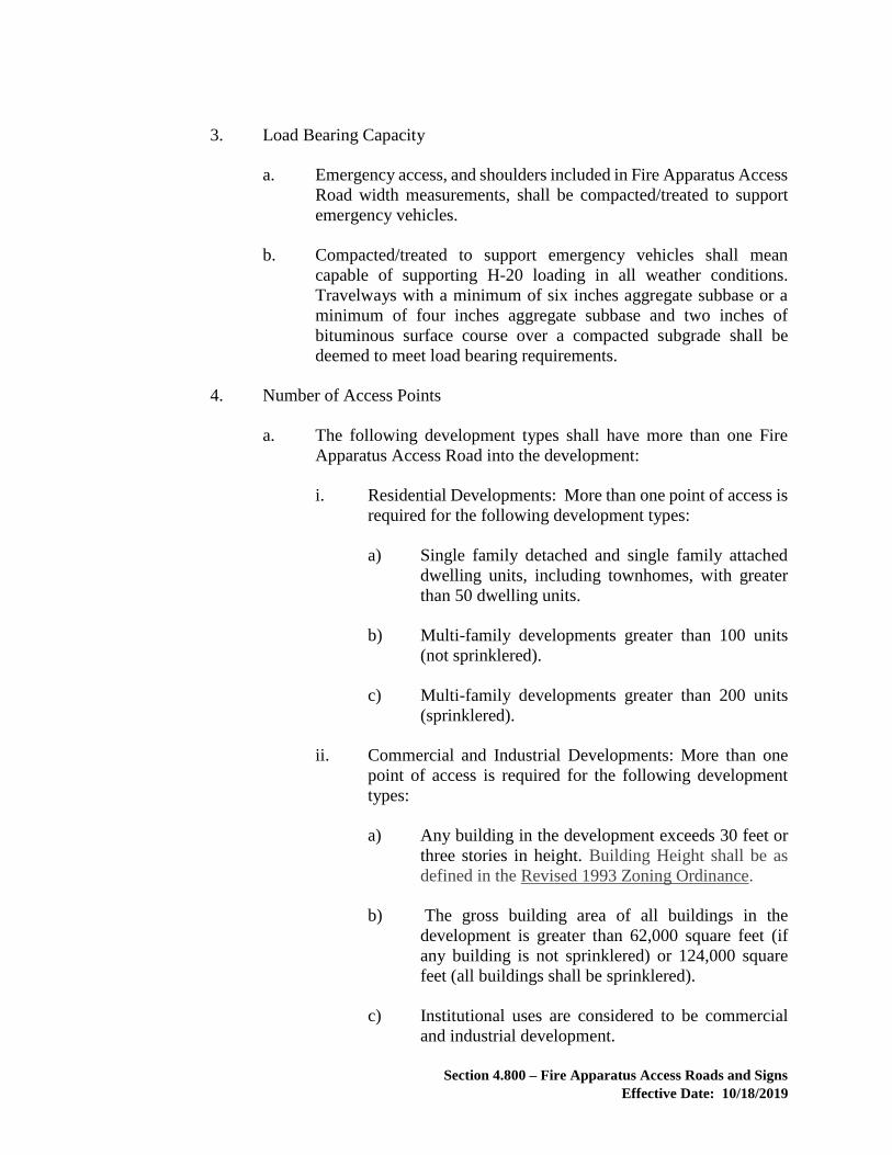
Section 4.800 – Fire Apparatus Access Roads and Signs
Effective Date: 10/18/2019
3. Load Bearing Capacity
a. Emergency access, and shoulders included in Fire Apparatus Access
Road width measurements, shall be compacted/treated to support
emergency vehicles.
b. Compacted/treated to support emergency vehicles shall mean
capable of supporting H-20 loading in all weather conditions.
Travelways with a minimum of six inches aggregate subbase or a
minimum of four inches aggregate subbase and two inches of
bituminous surface course over a compacted subgrade shall be
deemed to meet load bearing requirements.
4. Number of Access Points
a. The following development types shall have more than one Fire
Apparatus Access Road into the development:
i. Residential Developments: More than one point of access is
required for the following development types:
a) Single family detached and single family attached
dwelling units, including townhomes, with greater
than 50 dwelling units.
b) Multi-family developments greater than 100 units
(not sprinklered).
c) Multi-family developments greater than 200 units
(sprinklered).
ii. Commercial and Industrial Developments: More than one
point of access is required for the following development
types:
a) Any building in the development exceeds 30 feet or
three stories in height. Building Height shall be as
defined in the Revised 1993 Zoning Ordinance.
b) The gross building area of all buildings in the
development is greater than 62,000 square feet (if
any building is not sprinklered) or 124,000 square
feet (all buildings shall be sprinklered).
c) Institutional uses are considered to be commercial
and industrial development.

Section 4.800 – Fire Apparatus Access Roads and Signs
Effective Date: 10/18/2019
iii. Mixed Use Developments: The number of points of access
shall be determined based on the following equivalent
values. When the total value for a development is greater
than 200, more than one point of access shall be required.
Each single family detached/attached dwelling unit,
including townhome = 4
Each multi-family dwelling unit (not sprinklered) = 2
Each multi-family dwelling unit (sprinklered) = 1
Each building exceeding 30 feet or three stories in
height, containing commercial or industrial uses (with or
without dwelling units) = 200. Building Height shall be
as defined in the Revised 1993 Zoning Ordinance.
Every 620 square feet of building containing commercial
or industrial uses (if any building is not sprinklered) = 2
Every 620 square feet of building containing commercial
or industrial uses (if all buildings are sprinklered) = 1
iv. The Fire Marshal may also require more than one Fire
Apparatus Access Road into the development if there is the
potential for impairment of such Fire Apparatus Access
Road by vehicle congestion, condition of terrain, climatic
conditions or other factors that could limit access.
b. Where more than one fire apparatus access road is required, distance
between the access points also will be evaluated. Considerations
shall include, without limitation, median divided roadways,
sprinkler systems, and non-combustible construction materials.
5. Turn Arounds
a. Dead end fire apparatus access roads in excess of 150 feet in length,
as measured along the center line from the curb line to the end of the
fire apparatus access road, shall be provided with an approved turn
around for fire apparatus within 150 feet of the end of the fire
apparatus access road, unless otherwise approved by the Fire
Marshal.
b. Approved turn arounds in Figure 18 depict minimum dimensions
and do not require any further analysis. Other turn around geometry
Section 4.800 – Fire Apparatus Access Roads and Signs
Effective Date: 10/18/2019
that can accommodate an SU-40 design vehicle (AASHTO) may be
approved by the Fire Marshal.
c. Approved turn arounds depicted in Figure 18 require fire lane
identification.
6. Geometric Standards
a. Turning radii shall be designed to accommodate an SU-40 design
vehicle (AASHTO).
b. The grade or slope shall not exceed 14 percent along the centerline
of the Fire Apparatus Access Road.
C. Fire Lane Identification
1. Timing:
a. Prior to the issuance of an occupancy permit for any facility,
building, or portion of a building hereafter constructed, Fire Lane
Identification shall be provided along any Fire Apparatus Access
Road serving such facility, building, or portion of a building.
2. Specifications:
a. Fire Lane signs required by Chapter 486 of the Codified Ordinances
of Loudoun County shall meet the design and installation standards
set forth in Figure 16.
b. Fire Lane Identification shall be provided as follows:

Section 4.800 – Fire Apparatus Access Roads and Signs
Effective Date: 10/18/2019
Type Signage Curb/Edge of Pavement Painting
Length of Curb or
Shoulder ≤ 30 feet
One D sign installed on center. In lieu of the D sign, curbing or edge
of pavement may be painted with a 6-
inch yellow stripe with "FIRE LANE"
stenciled in black in 4 inch letters on
center.
Length of Curb or
Shoulder > 30 feet
One A sign installed at one end and
one C sign installed at the other end
with directional arrows pointing in.
and
Where the space between the A and
the C sign exceeds eighty (80) feet,
intermediate B sign(s) shall be
installed. Spacing between signs
shall not exceed eighty (80) feet.
In lieu of intermediate B signs, curbing
or edge of pavement may be painted
with a 6-inch yellow stripe with "FIRE
LANE" stenciled in black every 50
feet in 4 inch letters.
Any entrance for
emergency access to
public pools
One A sign and one C sign on each
side of the entrance with directional
arrows pointing in.
As approved by the Fire Marshal.
Accessways for
emergency vehicles only
One sign installed on the barrier
securing the accessway that states
“No Parking Emergency Vehicles
Only.”
In lieu of signage along the
accessway, the edges of the
accessway shall be demarcated by
shrubs, boulders, fencing, or other
measures approved by the Fire
Marshal located within the
easement. The typical section of
the proposed accessway shall
include demarcation.
Table V: Fire Lane Signage and Painting
Section 4.800 – Fire Apparatus Access Roads and Signs
Effective Date: 10/18/2019
3. Exceptions:
a. Spacing between signs may be increased in Non-Suburban Zoning
Districts, subject to approval by the Fire Marshal.
b. Fire Lane Identification shall not be required if the travelway is part
of a residential development where all proposed lots are three (3)
acres in size or greater.
D. Fire Apparatus Access Road Gates or Barriers
1. Gates securing fire apparatus access roads shall comply with all of the
following criteria:
a. For a two-way travelway, the minimum unobstructed gate opening
width shall be 20 feet. For a one-way travelway, the minimum
unobstructed gate opening width shall be 12 feet.
b. Construction of gates shall be of materials that allow manual
operation by one person.
c. Electric gates shall be equipped with a means of opening the gate by
public safety personnel for emergency access. Emergency opening
devices shall be approved by the Fire Marshal.
d. Manual opening gates shall not be locked with a padlock or chain
and padlock unless they are capable of being opened by means of
forcible entry tools or when a key box containing the key(s) to the
lock is installed at the gate location.
e. Locking device specifications shall be submitted for approval by the
Fire Marshal.
f. Electric gate operators, where provided, shall be listed in accordance
with UL 325.
g. Gates intended for automatic operation shall be designed,
constructed and installed to comply with the requirements of ASTM
F 2200.
2. Barriers securing accessways for emergency vehicles only shall comply
with all of the following criteria:
a. Shall be constructed out of high-visibility plastic chain, delineators,
or materials as approved by the Fire Marshal.

Section 4.800 – Fire Apparatus Access Roads and Signs
Effective Date: 10/18/2019
b. Shall not be locked with a padlock or chain and padlock unless they
are capable of being opened by means of forcible entry tools or when
a key box containing the key(s) to the lock is installed at the location.
E. Traffic Signal – VDOT and Loudoun County Fire and Rescue (LCFR) Preemption
Control Devices
New traffic signals and modifications to existing signalized intersections shall
include preemption control devices that are approved by both VDOT and LCFR
pursuant to Chapter 424 of the Codified Ordinances of Loudoun County.
4.820 STREET NAME SIGNS
Permanent street name signs shall be installed and maintained in accordance with the
specifications contained within the Loudoun County Codified Ordinances.
Temporary street names signs are required and shall be installed within 24 hours of
completion of clearing and in close proximity to each intersection location. Temporary
street name signs shall meet the specifications contained within the Loudoun County
Codified Ordinances (Chapter 1021) with the exception that a temporary post may be used
in lieu of the 2" x 2" square galvanized steel post required by the Ordinance. Temporary
signs shall be maintained until permanent signs are installed.
If the construction entrance for a work site is not at the location of a future street, it shall
be marked with a street name sign for the nearest future street no later than the day of the
preconstruction conference.
All new or modified mast arm traffic signal structures shall incorporate mast arm-mounted
street name signage and all required regulatory signage. The street name signage shall be
capable of properly identifying all intersection legs.
4.821 STREET EXTENSION SIGNS
Where a future street extension is anticipated to provide access to adjacent property, a sign
shall be installed indicating possible extension of the street. The sign shall be installed at
the terminus of the street or temporary cul-de-sac anticipated to be extended. The sign
shall be installed prior to installation of the base asphalt. The sign shall be in conformance
with Figure 17.
4.830 HANDICAP SIGNS
Handicap signs shall be provided on the plans in accordance with the specifications set
forth in the Americans With Disabilities Act of 1990, as amended.

Section 4.900 – Public Transit Bus Shelter Standards
Effective Date: 10/18/2019
4.900 PUBLIC TRANSIT BUS SHELTER STANDARDS
When a public transit bus shelter is proffered or otherwise provided, the shelter shall be
designed consistent with the policies in the Countywide Transportation Plan.
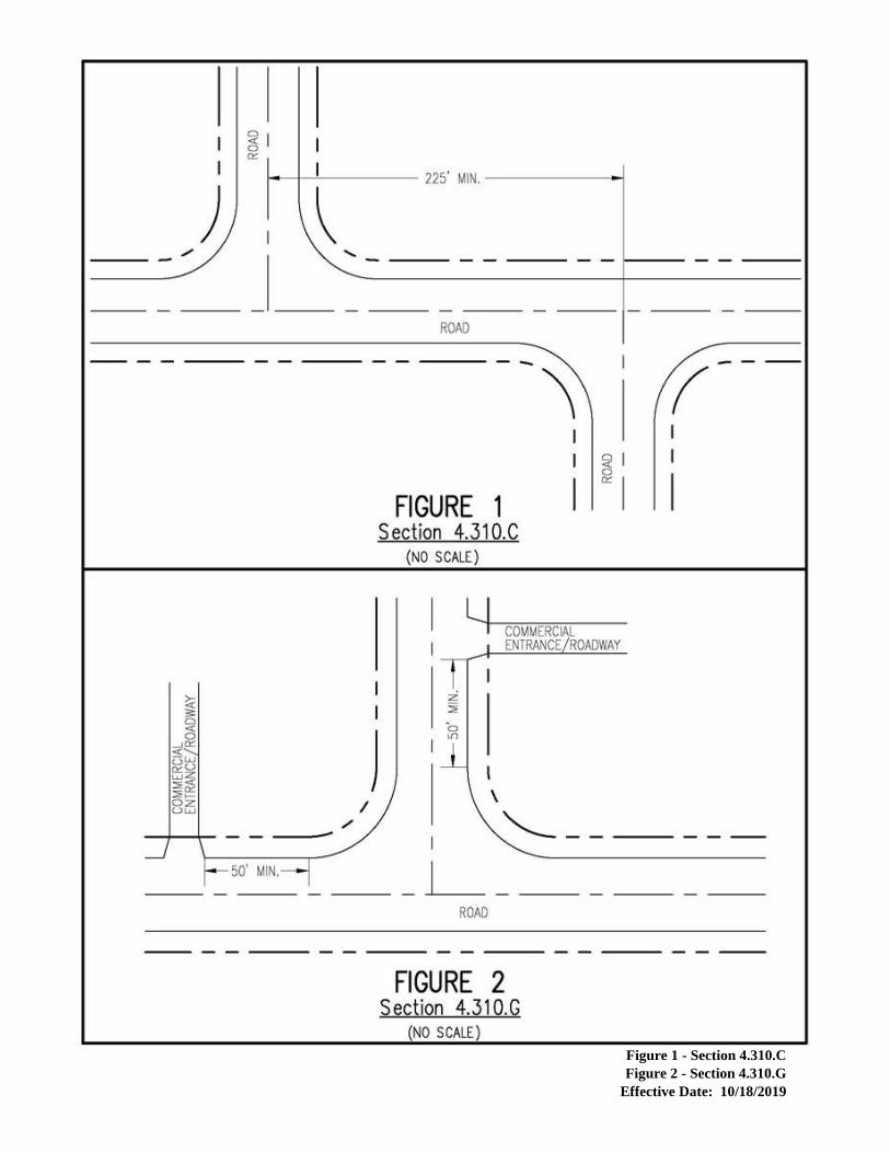
Figure 1 - Section 4.310.C
Figure 2 - Section 4.310.G
Effective Date: 10/18/2019
Figure 1 - Section 4.310.C
Figure 2 - Section 4.310.G

Figure 3 - Section 4.330.C.2
Figure 4 - Section 4.330.C.4
Effective Date: 10/18/2019
Figure 3 - Section 4.330.C.2
Figure 4 - Section 4.330.C.4

Figure 5 - Section 4.330.C.5
Effective Date: 10/18/2019
Figure 5 - Section 4.330.C.5

Figure 6 - Standard Curb and Gutter - Individual Driveway Entrance
Effective Date: 10/18/2019
Figure 6 - Standard Curb and Gutter - Individual Driveway Entrance

Figure 7 - Standard Pipestem Driveway Entrance
Effective Date: 10/18/2019
Figure 7 - Standard Pipestem Driveway Entrance

Figure 8 - Standard Driveway Detail - Shorter than 35’
Effective Date: 10/18/2019
Figure 8 - Standard Driveway Detail - Shorter than 35’

Figure 9 - Standard Driveway Detail - Longer than 35’
Effective Date: 10/18/2019
Figure 9 - Standard Driveway Detail - Longer than 35’

Figure 10 - Standard Curved Driveway Detail
Effective Date: 04/01/2015
Figure 10 - Standard Curved Driveway Detail

Figure 11 - Standard Side Load Driveway Detail
Effective Date: 10/18/2019
Figure 11 - Standard Side Load Driveway Detail

Figure 12 - Standard Private Driveway Entrance for Shoulder Sections VDOT Road
Effective Date: 10/18/2019
Figure 12 - Standard Private Driveway Entrance for Shoulder Sections VDOT Road

Figure 13 - Cross Section for Standard Private Driveway Entrance for Shoulder Sections VDOT Roads
Effective Date: 10/18/2019
Figure 13 - Cross Section for Standard Private Driveway Entrance for Shoulder Sections
VDOT Roads

Figure 14 - Section 4.400.B.1
Effective Date: 10/18/2019
Figure 14 - Section 4.400.B.1

Figure 15 – Alley Entrance to Public Street
Effective Date: 10/18/2019
Figure 15 - Alley Entrance to Public Street

Figure 16 - Fire Lane Sign Type and Specifications
Effective Date: 10/18/2019
Figure 16 - Fire Lane Sign Type and Specifications

Figure 17 – Street Extension Sign Type and Specifications
Effective Date: 10/18/2019
Figure 17 - Street Extension Sign Type and Specifications

Figure 18 – Loudoun County Fire Apparatus Access Road Turn Around Geometry
Effective Date: 10/18/2019
Figure 18 - Loudoun County Fire Apparatus Access Road Turn Around Geometry
FIGURE 18

CHAPTER 5.000
WATER RESOURCE MANAGEMENT
5.100 PURPOSE/OBJECTIVES
5.200 DESIGN STANDARDS
Table 1 – Preferred Design Reference
5.201 EASEMENTS
Table 2 – Easements
5.210 HYDROLOGIC DESIGN
5.220 HYDRAULIC DESIGN
Table 3 – Frequently Used Hydraulic Design Criteria Table – Open Channel Flow Table – Miscellaneous Grading Criteria
5.225 STORMWATER MANAGEMENT - GENERAL CRITERIA
5.230 STORMWATER MANAGEMENT - TECHNICAL CRITERIA
Table – Acceptable BMP Measures – Petroleum Products and Hazardous Substances
5.300 RESERVED
5.400 FLOODPLAINS
5.410 FLOODPLAIN INFORMATION TO BE SUBMITTED WITH LAND
DEVELOPMENT APPLICATIONS
5.411 FLOODPLAIN STUDIES
5.420 RESERVED
5.430 RESERVED
5.440 DEVELOPMENT IN FLOODPLAINS
5.441 DECLARATION OF NO IMPACT TO FLOODPLAIN
5.442 FLOODPLAIN ALTERATIONS

Figure 1 - Level Spreader with Plunge Pool
Figure 2 - Loading Plane of a Building Foundation
Figure 3 - Stack Trash Protection for Low Flow Orifice
Figure 4 - Typical Floodplain Application Process

Section 5.100 – Water Resource Management – Purpose/Objectives
Effective Date: 11/01/2016
CHAPTER 5.000
WATER RESOURCE MANAGEMENT
5.100 PURPOSE/OBJECTIVES
A. The purpose of this chapter is to establish minimum acceptable design criteria
necessary to promote adequate drainage and limit adverse impacts upon the health,
safety, and welfare of the general public and the County’s water resources that may
result from unregulated stormwater runoff and to set forth design criteria. An
additional purpose is to ensure compliance with relevant state and federal laws and
regulations related to water resource management which address pollution control
and prevention, runoff volume reduction, stormwater treatment, stream channel
protection, and flood protection. To meet these objectives, it is necessary to
perform a detailed assessment of a given drainage area, stream geometry, and the
natural drainage shed hydrology prior to the development of a stormwater
management plan required as part of a land development application. The use of
Environmental Site Design (ESD), described in Section 5.200.B, is a recommended
technique for addressing these water resource management issues associated with
development.
B. The design of an adequate drainage system must (a) account for both off-site and
on-site stormwater runoff; (b) honor natural drainage divides; and (c) adequately
convey stormwater runoff in compliance with this chapter. Adequate drainage must
also include provisions for overland relief to accommodate stormwater runoff in
excess of the design storms without damaging or endangering adjacent structures
or properties.
C. Stormwater management shall be provided in conjunction with proposed
development, in accordance with the criteria contained in this chapter. Stormwater
management serving single or multiple properties, sites or drainage areas may be
incorporated within proposed developments. Regional stormwater management
provisions shall be followed in accordance with any County approved drainage
districts.
D. An objective of the County is to promote water quality by implementing Best
Management Practices (BMP) measures that address water quality impacts of
development on the surface and groundwater resources of the County.
E. The floodplain management criteria specified within the Zoning Ordinance are
based on a formal determination of the regulatory flood elevations. Detailed
floodplain studies shall be prepared in accordance with the criteria contained within
this chapter.

Section 5.200 – Design Standards
Effective Date: 11/01/2016
5.200 DESIGN STANDARDS
A. Except where specifically supplemented herein, the design provisions of the most
current adopted VDOT Drainage Manual, Virginia Erosion and Sediment Control
Handbook, Virginia Stormwater Management Handbook, and all other reference
documents referred to herein, at the time of application acceptance shall apply in
all cases.
Table 1 – Preferred Design Reference– to be utilized when more
than one approved reference may address the same design item. Design Item Reference
Storm Sewer & Culvert Outlet Protection - Dimensions Std. & Spec. 3.18 in the Virginia Erosion and Sediment Control Handbook (VESCH)
Riprap Channel Design – Side Slopes ≤ 3:1 Std. & Spec.’s 3.17 & 3.19 in the VESCH
Riprap Channel Design – Side Slopes > 3:1 (Tractive Force Analysis)
Appendix 3.19-a in Std. & Spec. 3.19 in the VESCH
Required Depth of Stone in Riprap Channel Design Std. & Spec. 3.19 in the VESCH
“Applicable Area” Boundary for Performance-Based Water Quality Calculations
Section 2-3.3 in Chapter 2 of the Virginia Stormwater Management Handbook
Runoff Coefficient, “c,” for Rational Method Calculations
Appendix 6E-1 in Chapter 6 of the VDOT Drainage Manual
Curve Number, “CN,” for NRCS Calculation Methods Table 5-5 in Chapter 5 of the VESCH
Roughness Coefficient for Various Man-made and Natural Channels, and Floodplains
Appendix 7D-1 in Chapter 7 of the VDOT Drainage Manual
Maximum Allowable Velocity for Natural Channels – Based on Soil Types & Rockiness
Appendices 7D-2 & 7D-6 in Chapter 7 of the VDOT Drainage Manual
Correction Factor for Maximum Permissible Velocities for Sinuous Natural Channels
Table 5-23 in Chapter 5 of the VESCH
Floodplain Modeling with HEC-RAS – Cross Section Establishment (location, order, orientation, etc.)
Chapter 3 & 5 in the HEC-RAS User’s Manual

Section 5.200 – Design Standards
Effective Date: 11/01/2016
B. Environmental Site Design (ESD) techniques as referred to in the Virginia
Stormwater Management Handbook may be incorporated into drainage designs in
order to meet local and State goals for stormwater management. ESD integrates
small-scale stormwater management practices, Low-Impact Development (LID)
techniques, non-structural techniques, and better site planning to mimic natural
hydrologic runoff characteristics and minimize the impact of land development on
water resources. This includes:
1. Optimizing conservation of natural features (e.g., drainage patterns, soils,
vegetation, etc.);
2. Minimizing impervious surfaces;
3. Utilizing BMPs located close the pollutant source that reduce stormwater
runoff volume such as bioretention facilities, infiltration basins, wet and dry
swales, etc.;
4. Slowing down runoff to maintain pre-development stormwater discharge
timing and to increase infiltration and evapotranspiration on the
development site;
5. Using other non-structural practices or innovative technologies approved by
the Director; and,
6. Concurrently planning for stormwater management, density, parking, fire
and rescue, tree conservation, and other local requirements.
When designed, constructed, and maintained effectively, ESD achieves numerous
stormwater management goals as well as other complimentary ecological, social,
and economic benefits, which include the following:
7. Reducing or eliminating stormwater runoff from a site to adjacent
impervious surfaces or conveyance systems benefits the watershed as a
whole by reducing pollutant loading and erosion from uncontrolled runoff
into waterways;
8. The use of infiltration-type BMPs may be used to satisfy both quality and
quantity control requirements.
9. ESD practices that preserve existing trees and other vegetation protect and
provide habitat and may be used to satisfy both quality and quantity control
requirements, as well as Zoning Ordinance requirements.
10. Replacing impervious surfaces with trees and other vegetation can also
reduce urban heat island effects, in turn saving energy and improving
human comfort.

Section 5.200 – Design Standards
Effective Date: 11/01/2016
11. The aesthetic appeal of adding vegetated areas to an urban environment has
been shown in multiple studies to benefit human health and well-being as
well as increase property values and attractiveness to business patrons.
5.201 EASEMENTS
Floodplain, storm drainage/stormwater conveyance systems, and stormwater management
facilities shall be located within an easement dedicated to Loudoun County in accordance
with the following table:
Table 2 – Easements
Easement
Type
Applicability Length Width
Floodplain All major or minor
floodplain on the subject
property.
Defined by 100-year
floodplain limit.
Defined by 100-year
floodplain limit.
Storm
Drainage
Overland relief at sump
locations on public roads
with curb and gutter.
Easement shall extend
from the public street
to the rear property
line of lots abutting
the street.
10 feet
Storm
Drainage
Manmade open channels:
1) that convey concentrated
offsite runoff; or
2) that convey greater than 2
cubic feet per second for the
10-year storm across a
residential lot/parcel; or
3) that drains runoff across
more than two full
residential lots, beginning
where the channel enters the
third lot.
Easement shall extend
the length of the
manmade open
channel. An easement
shall not be required
for commercial or
multi-family sites that
solely convey on-site
drainage.
Design flow width, plus
5 feet on each side (15-
foot minimum).

Section 5.200 – Design Standards
Effective Date: 11/01/2016
Easement
Type
Applicability Length Width
Storm
Drainage
Storm sewers/culverts.
Easement shall extend
the length of the
storm sewer and
culvert, including
outlet protection.
An easement shall not
be required for 1) on-
lot, private driveway
or trail culverts, or 2)
commercial or multi-
family sites that
solely convey on-site
drainage.
The minimum storm
sewer easement widths
are depicted below:
Pipe
Size
Minimum
Easement
Width
Up to
18
inches
10 feet
21 to
33
inches
15 feet
36 to
48
inches
20 feet
54 to
72
inches
24 feet
Storm
Drainage
Ponding areas at culverts
and inlets that are located
within or adjacent to a storm
drainage easement.
Easement shall
completely
encompass the 10-
year ponding area.
Easement shall
completely encompass
the 10-year ponding area.
Storm
Drainage
Ponding areas at existing
culverts and inlets on
property not owned or
controlled by the applicant.
N/A No easement required.
Storm
Drainage
On-site preserved (natural)
open channels that convey
greater than 2 cubic feet per
second.
Easement shall extend
on-site to the
floodplain, property
line, or the point the
conveyance system
becomes
jurisdictional
(intermittent stream,
perennial stream, or
wetland).
Design flow width, plus
5 feet on each side (15-
foot minimum).
Storm
Drainage
Stormwater management
facilities: above ground
structures, including ponds,
bioretention areas, etc.
N/A 10 feet beyond
embankment toe and the
100-year water surface
elevation.

Section 5.200 – Design Standards
Effective Date: 11/01/2016
Easement
Type
Applicability Length Width
Storm
Drainage
Stormwater management
facilities: vegetative filter
strip used as water quality
BMP below a level spreader.
To the end of the
filter strip.
Width of level spreader
rigid lip.
Storm
Drainage
Stormwater management
facilities: underground
stormwater management
structures (e.g., Stormfilter,
Filterra, oil/water
separators).
N/A 10 feet beyond periphery
of the structure.
Storm
Drainage
Access roadways for
stormwater management
facilities.
Length of the access
road.
1 foot on each side of the
roadway.
VRRM
Land Cover
Easement
Forest/open space used to
meet VRRM requirements.
Defined by the limits
of the forest/open
space.
Defined by the limits of
the forest/open space.
5.210 HYDROLOGIC DESIGN
Unless otherwise specified, all hydrologic analyses shall be based on the existing watershed
characteristics and how the ultimate development condition of the subject project will be
addressed. The following hydrologic methods and values are acceptable:
A. The hydrologic methodologies provided by the Virginia Stormwater Management
Handbook. The use of the Rational and the Modified Rational Methods shall be
limited by the following:
1. In the calculation of the peak discharge for storm sewer and culvert design,
the maximum drainage area shall be 200 acres.
2. In the calculation of the peak discharge and runoff volume for conveyance
system protection and flood protection as defined in Section 5.230, the
drainage area shall be less than 20 acres and the maximum time of
concentration shall be less than 20 minutes.
B. HEC-1 Model or HEC-HMS Model utilizing Natural Resources Conservation
Service rainfall runoff relationships.
C. Other methods are subject to approval by the Director.
D. Rainfall intensity and rainfall depth values for Loudoun County are based upon
National Oceanic and Atmospheric Administration and VDOT standards that are
found at the following County website address: www.loudoun.gov/fsm-rainfall.

Section 5.200 – Design Standards
Effective Date: 11/01/2016
5.220 HYDRAULIC DESIGN
This section identifies specific criteria for the design of all drainage systems including
sizing, hydraulic performance, easement requirements, pipe materials, etc. Design flows
will be determined utilizing methods discussed in this chapter and the drainage system will
be sized to collect and/or convey the design flow at all points along the system.
A. General Design Criteria
1. Proposed storm drainage systems shall be designed to convey the runoff
from a 10-year rainfall when its intended use is to function as the primary
drainage system. The primary drainage system consists of storm sewers,
culverts, and open drainageways designed to convey concentrated runoff to
adequate channels. The primary system does not include overlot grading
and other minor conveyance swales.
2. Drainage systems shall not be terminated at the project boundary unless an
adequate channel exists at that point, as defined in this chapter.
3. Drainage systems shall be designed to provide, as a minimum, overland
relief for the 100-year rainfall without increasing the flood potential for
nearby buildings. Calculations shall be provided to show appropriate
overland relief when the primary drainage system is adjacent to the
buildings. In lieu of calculations, the plans must indicate at least a minimum
of 1 foot of overland relief being provided between the relief point and the
lowest entry point of any building.
4. Culverts, storm sewers, man-made channels and other conveyance systems
discharging into open channels shall be designed so as to minimize the skew
angle with such open channel. If the skew angle with the centerline of the
receiving channel is greater than 45 degrees, install or extend a non-erodible
lining so that it encompasses 1.5 times the 10-year flow depth at least 15
feet upstream and downstream of the channel bend.

Section 5.200 – Design Standards
Effective Date: 11/01/2016
Table 3 – Frequently Used Hydraulic Design Criteria
Design Item Design Criteria Reference
Roughness Coefficients, n, & Maximum Allowable Velocity, v, in feet per second (fps), for Various Sizes of Riprap.
Size n v*1
Class I 0.040 10 fps
Class II 0.042 13 fps
Class III 0.045 15 fps
Type I 0.047 20 fps
Type II 0.050 20+ fps
*1 Use this criteria when channel side slopes are ≤ 3:1
Roughness -Appendix 7D-1 in Chapter 7 of the VDOT Drainage Manual
Velocity - Ishbash Equation/Curve
Roughness Coefficients, n, & Maximum Allowable Velocity, v, for Vegetative Linings With & Without Erosion-Resistant Matting
Lining n v
Grass -maintained 0.035 4 fps*2
Grass - not maintained 0.050 4 fps*2
Sod -installed per VESCH 0.040 5 fps
EC-2 - temporary lining See Grass See Grass
EC-3 - permanent lining Type A Type B
0.050 0.050
7 fps*3 10 fps*3
*2 Lower by 25% for highly erodible soils & 5% - 22% for sinuous channels
*3 Use in absence of manufacturer’s information
VDOT Drainage Manual &
Virginia Erosion and Sediment Control Handbook (VESCH)
Storm Sewer & Culvert Outlet Protection – Velocity, v, vs. Type of Protection
v Type of Protection
2 fps to 5 fps Sod*4 or Class I Riprap*5
5 fps to 8 fps Class I Riprap
8 fps to 18 fps Class II Riprap
v > 18 fps Special design energy dissipaters, must meet approval of County and/or VDOT
*4 Sod installed per Std. & Spec. 3.33 in the VESCH
*5 Use “dry” riprap; also, use of natural rock on-site is encouraged when equivalency requirements can be met
VDOT Drainage Manual &
Virginia Erosion and Sediment Control Handbook (VESCH)

Section 5.200 – Design Standards
Effective Date: 11/01/2016
B. Storm Sewers/Culverts
1. Drainage design computations, as required by the VDOT Drainage Manual,
will be submitted with all Construction Plans and Profiles and/or Site Plans
containing storm sewer or culvert drainage systems.
2. The storm sewer and culvert designs shall include the following:
a. Construction information, including invert elevations, in and out;
size; type of pipe; gauge or class; length and percent of slope.
b. Storm sewer appurtenances shall be identified by type and number
(i.e., #00, MH-1, or MH-1 #2), including number and length of
throats and locations.
3. Culvert pipe sizes shall be determined in accordance with Hydraulic Design
Series No. 5, Federal Highway Administration, Department of
Transportation, or other VDOT-approved method.
4. Minimum size of concrete pipe to be used outside of the public right-of-way
will be 12 inches in diameter, where the distance between access openings
is less than 50 feet. The minimum size of pipe permitted within the public
right-of-way is 15 inches, unless otherwise specified in the VDOT Drainage
Manual.
5. There may be no reduction in pipe size greater than one standard increment
along the direction of flow within a storm sewer system.
6. The minimum cover for all drainage pipes within public or private Category
A and B roadways (street) rights-of-way shall be 2 feet, or one-half the
diameter of the pipe, whichever is larger. When the storm sewer pipe is
laid outside the street right-of-way or within Category C roadways, a
minimum of 2 feet of cover shall be required. For Low Impact Design in
non-load bearing conditions, a minimum of 1 foot of cover may be
provided. If the minimum cover requirements as set forth in this section
cannot be met, then stronger pipe classifications may be submitted for
approval. Minimum cover for single residential lot driveways shall conform
to VDOT standards.
7. Storm sewers shall be designed to provide a minimum velocity of no less
than 3 feet per second for the design flow. Pipe velocities shall not exceed
18 feet per second to avoid abrasion.
8. Except where noted otherwise, the maximum length between access
openings shall be 300 feet for pipes less than 36 inches in diameter or 500

Section 5.200 – Design Standards
Effective Date: 11/01/2016
feet for pipes 36 inches in diameter or greater. An access opening may be
an inlet, manhole, junction box, or other approved appurtenance.
9. The minimum slope of each segment of the storm sewer lines shall be 0.5
percent.
10. The need for concrete anchors must be investigated on storm sewer lines
with slopes of 16 percent or greater. If anchors are required, the design
engineer will show a detail on the plans with spacing requirements.
11. Storm sewer pipes larger than 15 inches in size shall not outfall in the front
yard of a single family detached lot less than or equal to 20,000 square feet,
but should be extended at least to the rear property line. Storm sewer
outfalls located in single family attached developments shall extend at least
to the rear lot line. If the storm sewer outfalls on a lot, or adjacent to a lot,
on which an existing building will remain, sufficient topographic
information shall be provided to verify overland relief.
12. The ends, entry or exit, of any storm sewer system and/or culvert shall be
provided with a standard end wall, head wall, curb inlet, yard inlet, flared
end section, or other appurtenance or structure suitable for the intended use
of the facility.
13. In addition to providing a water quality benefit, level spreaders may be used
to promote sheet flow across vegetated areas in lieu of channelization.
Level spreaders may also be utilized to diffuse flow before it enters a
riparian buffer or wetland. The following design criteria shall be followed
when utilizing level spreaders for these water quantity control purposes:
a. The criteria found at the Virginia Stormwater BMP Clearinghouse,
shall be used for design of level spreaders. The maximum allowable
design flow to a level spreader shall be 10 cubic feet per second
calculated using the Rational Method with a pre-determined rainfall
intensity of 1inch per hour.
b. When a level spreader is located within 50 feet of riparian buffers,
jurisdictional wetlands, and/or floodplains, additional energy
dissipation shall be provided by the addition of a stilling basin.
Please see Figure 1 for minimum design parameters for a level
spreader with a stilling basin.
c. The rigid lip of a level spreader may be constructed of timber for
discharges up to 5 cubic feet per second and shall be constructed of
concrete for discharges over 5 cubic feet per second.

Section 5.200 – Design Standards
Effective Date: 11/01/2016
d. Alternate designs which can be shown to promote non-erosive sheet
flow shall be subject to approval by the Director.
e. In order to apply stormwater pollutant removal credit to the
vegetated area below the level spreader, such area must meet the
requirements for “Sheet Flow to a Vegetated Filter Strip or
Conserved Open Space” found at the Virginia Stormwater
Management BMP Clearinghouse.
f. The maximum distance that discharge from a level spreader may be
considered to remain in sheet flow before reaching a stable outlet is
150 feet. To inhibit the re-concentration of flows, the average slope
over the entire length of the sheet flow shall be no greater than 8
percent.
g. Level Spreaders adjacent to storm sewer pipe outfalls shall not be
located any closer to the invert out of the pipe than the length of
required outlet protection.
h. A level spreader that receives discharge from storm sewer within the
VDOT right-of-way is subject to these additional constraints:
i. An effort shall be made to provide a minimum 1-foot vertical
clearance between the invert out of the storm sewer and the
top of the level spreader.
ii. If a 1-foot vertical clearance between the invert out of the
storm sewer and the top of the level spreader cannot be
achieved due to topographic or other site constraints,
evidence of positive relief for the 10-year storm without
restriction to the hydraulic function of the storm sewer shall
be provided.
14. No storm sewer shall be located within 5 feet of the loading plane of a
building foundation as depicted in Figure 2.
C. Open Channel Flow
1. An open channel is defined as a natural or manmade open drainageway. All
open channels shall comply with the following table:

Section 5.200 – Design Standards
Effective Date: 11/01/2016
Table – Open Channel Flow
Design Parameter On Lots ≤20,000 sq. ft. On Lots > 20,000 sq. ft. On Non-
Residential and
Common Areas
Max. allowable flow* 2 cubic feet per second No max., but if > 2 cubic
feet per second, open
channel should be 50 feet
from rear of house and 10
feet from side of house.
No Requirement
(NR)
Max. velocity* 4 feet per second 4 feet per second if armor
is not provided.
4 feet per second if
armor is not
provided.
Min. average slope* 2 percent 2 percent 1 percent
Max. width of flow* 10 feet NR NR
Max. depth of flow* 12 inches NR NR
Preserved natural open
channel > 2 cubic feet
per second.
Allowed within
easement
Allowed within easement Allowed within
easement
* in manmade open channels only.
Modifications may be approved by the Director to achieve ESD.
2. Open channels located inside the public right-of-way shall be designed and
constructed in accordance with the VDOT Drainage Manual. The
computations and the ditch cross-section shall be submitted with the plan
and profile sheets.
3. Open channels conveying over 2 cubic feet per second should be designed
for stable, subcritical flow. Local depressions or flat slopes may be allowed
along the flow path as part of ESD as long as they are designed to dissipate
within 48 hours, unless designed for water retention.
D. Grading Criteria
Overall grading on residential lots less than one acre in size shall meet the following
criteria:
1. In addition to the Individual Lot Grading Plan requirements of Chapter 8,
overall grading shall illustrate how the proposed house and lot grading will
be integrated into the overall drainage system proposed for a particular
section of development and shall honor drainage divides used for the storm
drainage design.

Section 5.200 – Design Standards
Effective Date: 11/01/2016
2. A building footprint shall be illustrated on the individual lots specifying the
proposed finished floor elevations for a given lot. The footprint should
accommodate the various potential home models without significant
alteration of the proposed drainage design and patterns.
3. Miscellaneous grading criteria:
Table – Miscellaneous Grading Criteria
Design Issue Criteria
Yard slopes ≤ 3:1 Stabilize with grass
Yard slopes > 3:1 Use ground cover that does not require regular
mowing
Surface drainage over curbs Yard overlot surface drainage in excess of 2
cubic feet per second (10-year design) should
not be directed to overtop the curb and gutter of
public or Category A private roads.
Yard grading To insure positive drainage away from the
foundation, provide 6 inches of fall for the first
10 feet and a minimum 2 percent * average grade
thereafter. Local depressions or flat slopes may
be allowed along the flow path as part of a low
impact development measure as long as they are
designed to dissipate within 48 hours, unless
designed for water retention.
* The minimum grade may be reduced to decrease disturbed area and to promote tree
conservation if positive drainage can otherwise be achieved on the lot.
E. Pipe Materials
1. All pipe used for the construction of drainage systems and/or stormwater
management facilities shall be concrete or High Density Polyethylene
(HDPE), as specified below. HDPE pipe is permitted in any particular
application if VDOT approves its use, design and specifications during their
review of the CPAP or Site Plan. Alternate materials can be utilized where
specifically permitted below or in accordance with waivers granted by the
Director of Building and Development.
a. All concrete pipe shall be a minimum Class III. All HDPE pipe shall
meet the most recently published VDOT specifications. Alternate
materials, where permitted, shall meet the current VDOT
requirements.

Section 5.200 – Design Standards
Effective Date: 11/01/2016
b. Metal and/or other plastic pipe may be designated for use on-site
where the facility is not located within an easement. All
construction and use of these materials must be accomplished in
accordance with manufacturer's recommendations.
c. Corrugated Metal Pipe used for Category C private roadway
culverts shall meet current VDOT specifications.
d. HDPE pipe shall not be permitted in pond embankments.

Section 5.200 – Design Standards
Effective Date: 11/01/2016
5.225 STORMWATER MANAGEMENT - GENERAL CRITERIA
A. General Criteria
1. Stormwater management facilities may consist of either above grade or
underground facilities; however, underground facilities are permitted only
within non-residential areas or high-density residential zones. Above grade
stormwater management facilities may be designed as either wet or dry
facilities.
2. Stormwater management facilities serving single or multiple properties,
sites, or drainage areas may be incorporated within proposed developments.
3. Regional stormwater management is defined as facilities and/or design
criteria identified in a County approved drainage district study to control
increases in runoff from developed sites within the established district.
Stormwater management requirements identified with these studies must be
met in conjunction with any applicable land development activity.
4. All stormwater management facilities shall be located within an easement
dedicated to Loudoun County. Such facilities shall be maintained by the
landowner, an owners or homeowners association, or other legal entity
approved by the Board of Supervisors, to the extent not maintained by the
County pursuant to Chapter 1096 of the Codified Ordinances of Loudoun
County (C.O.). Maintenance responsibilities shall be established in the
required Deed of Dedication, in a form acceptable to the County Attorney.
5. ESD techniques may be incorporated into stormwater management designs.
6. Regular maintenance is vital to the proper functioning of stormwater
management facilities. Designs shall consider and address the future
operation and maintenance requirements of stormwater management
facilities.
a. All required access-ways and easements shall be designated on
plans and cleared, graded, or constructed with the facility
construction.
b. Proximity of facilities to the public right-of-way shall be considered
in order to minimize the length of the access-way.
c. Multiple access paths to major facilities should be provided.
d. Specifically delineated access easements may be required where
stormwater management facilities are surrounded by residential lots.
Section 5.200 – Design Standards
Effective Date: 11/01/2016
7. All stormwater management retention ponds (wet ponds) that are not
subject to a separate negotiated stormwater maintenance agreement with the
County pursuant to Chapter 1096 of the C.O. must be periodically
maintained and inspected by the property owner or HOA in accordance with
the Virginia Stormwater Management Handbook. Such maintenance may
include removal of silt, litter and other debris from all catch basins, inlets
and drainage pipes, grass cutting and vegetation removal, and necessary
replacement of landscape vegetation and any repair or replacement of
structural features. The legal documents recorded to grant the easement for
the stormwater management facilities must provide for an annual inspection
and report in accordance with Chapter 1096 of the C.O.
8. When outfalls from stormwater management facilities are discharged to a
receiving channel, energy dissipators shall be placed at the outfall as
necessary to provide a stabilized transition from the facility to the receiving
channel.
B. Facility Design Standards
1. Where required by previous approvals, Preliminary Stormwater
Management Plans prepared in conjunction with proposed development
shall include the following information:
a. General location of proposed centralized stormwater management
facilities shown on available topographic mapping.
b. Drainage area delineation and computations for each facility.
c. Preliminary calculations to identify sizing criteria.
d. Proposed phasing of facility construction in conjunction with
development phasing.
2. A narrative shall be provided with all stormwater management designs
which includes the following information:
a. A description of pre- and post-development site conditions.
b. An explanation of the stormwater management strategies used to
meet both the water quantity and water quality technical
requirements of this Chapter.
c. A description of the stormwater management facilities employed
which includes:
i. Type of facility.

Section 5.200 – Design Standards
Effective Date: 11/01/2016
ii. Location of facility, to include geographic coordinates. This
information may be shown on the plans in lieu of the
narrative.
iii. Acres treated.
iv. Description of the discharge point.
d. The mechanism thorough which the facilities will be operated and
maintained after construction is complete.
3. Computations submitted with detailed designs for proposed stormwater
management facilities to demonstrate the attenuation of stormwater runoff
(e.g., wet ponds, extended-detention ponds, oversized stormwater pipes or
vaults, etc.) shall include the following information:
a. Stage - storage relationship for the facility.
b. Stage - discharge relationship for the proposed outfall structure(s)
including computations.
c. Routing program utilized (may not be applicable in conjunction with
facilities designed using previously approved graphical and/or short
cut methodologies).
d. Hydrologic computations as provided in this chapter.
4. The minimum low flow orifice diameter to be used for facilities which
provide extended detention is 2.5 inches with open grill trash protection. If
the “stack” filtering system (see Figure 3) is utilized for trash protection, the
orifice diameter may be reduced to 1.75 inches.
5. All dry stormwater management facilities shall incorporate appropriate
provisions for low flow conveyance without using concrete trickle ditches.
6. Underground Stormwater Management Facilities – Design of Underground
Stormwater Management Facilities including water quality inlets shall
include the following information:
a. For structures that rely on soil suitability, a geotechnical report shall
be provided which addresses the soil suitability, compatibility with
materials to be used, and pH and corrosiveness of the soil and water
runoff from the drainage area.
b. Demonstrate that the facility will meet all stormwater management
regulations of this chapter.

Section 5.200 – Design Standards
Effective Date: 11/01/2016
c. Detailed description and specifications of the facility, how the
facility will be constructed or installed, and the manufacturer’s
and/or designer’s recommendations for maintenance and
maintenance schedule shall be provided.
7. Stormwater Management Facilities with Infiltration – Design of measures
that rely on infiltration (through either engineered media, stone, or in situ
soils) shall include the following:
a. Verification that the Seasonal High Water Table (SHWT), to include
the “perched” condition, is at least 2 feet below the bottom of the
facility shall be accomplished by one of the following methods:
i. Observation of ground water monitoring wells over a 12-
month period. Testing duration may be reduced if testing is
only performed from November 1 through May 31. Months
June through October shall not be included unless the value
of the Palmer Drought Severity Index (PDSI) is equal to or
greater than 2.0 (i.e. wet).
ii. Site-specific evaluation of the redoximorphic features within
the soil profile by a Virginia Licensed Soil Scientist
(C.P.S.S), Certified Professional Geologist (C.P.G.),
Professional Wetland Delineator (PWD), or Licensed
Professional Engineer (P.E.) who has completed a soil
morphology training class offered through Northern
Virginia Soil and Water Conservation District (NVSWCD)
or equivalent as determined by the Director.
a) The evaluation shall include a soil description that
includes all soil horizons and are described per
ASTM D-2488 (Description and Identification of
Soils Visual-Manual Procedure) or National
Cooperative Soil Survey standards as set forth in the
National Soil Survey Handbook. Colors shall be
identified using the Munsell System of Color
Notation.
b) Fieldwork shall be documented as being performed
by the professional who meets the certification
requirements in subsection ii above.
c) All fieldwork shall be subject to review and
confirmation by the County.
iii. Use of data from the USDA Soil Data Mart.

Section 5.200 – Design Standards
Effective Date: 11/01/2016
iv. However, if the 2-foot separation between the bottom of the
facility and the SHWT cannot be achieved, the incorporation
of an underdrain system and an impermeable clay (Ksat ≤
1x10⁻⁶ cm/s) or geotextile liner is acceptable.
8. The following information shall be included with designs for dam
embankments related to stormwater management or recreational water
impoundments.
a. A geotechnical report shall be provided which addresses the soil
seepage through the embankment and body of the pond, contains an
embankment design, and addresses the soil and water pH and
erosiveness related to the principle spillway pipe materials.
b. No landscape plantings other than grass or groundcover shall be
proposed on the dam embankment.
c. The pond outfall shall be far enough from the property line to
achieve an adequate transition in accordance with the Virginia
Stormwater Management Handbook and the Virginia Erosion and
Sediment Control Handbook.
d. Low-level drains shall be provided for wet ponds to facilitate
maintenance and sediment removal where a gravity outfall is
available.
e. Pond structures shall be engineered to assure structural integrity
during the 100-year storm event.
9. The Virginia Soil and Water Conservation Board regulates certain
impounding structures defined therein (see Virginia Dam Safety Act,
Section 10.1-604 et seq.). The design criteria presented below apply to
impounding structures (wet ponds) which have a height greater than or
equal to 6 feet and are governed by the Virginia Dam Safety Act. These
impounding structures shall also conform to all design criteria listed in the
State Impounding Structure Regulations (4VAC50-20-10 et seq.). In
addition, the design criteria presented below apply to all impounding
structures which have a height greater than or equal to 15 feet.
a. The height of the dam (Hd) shall be defined as the vertical distance
from the natural bed of the stream or watercourse measured at the
downstream toe of the impounding structure to the top of the
impounding structure.

Section 5.200 – Design Standards
Effective Date: 11/01/2016
b. A slope stability analysis shall be performed to address seepage
through the structure, pore water pressure within the structure, slope
pressure, and slope protection.
c. Emergency spillways shall be designed to pass at minimum a 100-
year storm with the primary spillway assumed to be 100 percent
clogged without endangering the integrity of the impounding
structure.
d. A maintenance program shall be provided to the Department of
Building and Development and implemented in conformance to
"Safety Evaluation of Small Earth Dams", 2nd Ed., Natural
Resources Conservation Service, Virginia Department of
Conservation and Historic Resources.
e. An Emergency Action Plan, as defined in the Act, shall be submitted
and maintained by the owner of the dam. The owner shall be
responsible for notifying the 24 Hour Dispatch Center at "911".

Section 5.200 – Design Standards
Effective Date: 11/01/2016
5.230 STORMWATER MANAGEMENT - TECHNICAL CRITERIA
Adherence to the technical criteria in the Virginia Stormwater Management Program
Permit Regulations (9VAC25-870-10 et seq.), the Stormwater BMP Clearinghouse
Website http://www.vwrrc.vt.edu/swc/, and in this Chapter shall be required. Variations
(WAIV) of the requirements of this section pursuant to FSM Section 1.200.A shall not be
permitted. Instead, the Director may grant exceptions to the requirements of this Section in
accordance with Chapter 1096 of the C.O.
A. Water Quantity Criteria
1. General Requirements
a. Concentrated stormwater runoff from development sites shall be
discharged directly into a conveyance system, such as a well-defined
natural or constructed receiving channel, pipe, or pipe system. A
receiving channel shall have a defined bed and bank, verified by
either of the following:
i. The cross section of the receiving channel has a maximum
bottom width to flow depth ratio of 35:1; or,
ii. For a receiving channel with a bottom width to flow depth
ratio greater than 35:1, photos of the cross-section and
overbank areas, along with any pertinent calculations shall
be provided to show that channel meandering and erosion
will not occur and that flow moving into overbank sections
will not adversely impact the adjacent property.
b. Conveyance system protection and flood protection analyses shall
be provided at every discharge point of concentrated flow
originating from site improvements.
c. Increased volumes of sheet flow originating from site improvements
that may cause erosion or flooding on down-gradient property shall
be identified and diverted to a stable outlet or stormwater
management facility that provides the required conveyance system
protection and flood protection.
d. Offsite stormwater management facilities may be utilized to meet
the requirements of this section where (1) it can be shown that the
stormwater management facility was designed to accommodate the
subject area, and (2) an approved maintenance agreement with the
owner of the stormwater management facility is executed in
accordance with Chapter 1096 of the C.O.

Section 5.200 – Design Standards
Effective Date: 11/01/2016
2. Conveyance System Protection
Conveyance systems shall meet the following criteria:
a. When stormwater from a development is discharged to a Manmade
Conveyance Systems – Constructed or improved open channels,
culverts, and storm sewer.
i. The manmade conveyance system shall convey the post-
development peak flow rate from the 2-year 24-hour storm
event without causing erosion of the system; or
ii. The Energy Balance Methodology described in Section
5.230.A.2.c. shall be met.
b. When stormwater from a development is discharged to a Restored
Conveyance Systems – Streams restored using natural channel
design techniques which include an analysis of geomorphic
processes to create, rehabilitate, restore or stabilize the channel so
that it conveys its bankfull storm event within its banks and allows
larger flows to access its floodplain.
i. The development, in combination with other stormwater
runoff to the stream, shall be consistent with the design
parameters of the restored conveyance system that is
functioning in accordance with the design objectives; or
ii. The Energy Balance Methodology described in Section
5.230.A.2.c. shall be met.
c. When stormwater from a development is discharged to a Natural
Conveyance Systems – Natural perennial or intermittent streams,
unimproved ephemeral channels, or swales.
The maximum peak flow rate from the post-development 1-year 24-
hour storm shall be calculated in accordance with the Energy
Balance Methodology below or another methodology that is
approved by the Director and the Water Control Board.

Section 5.200 – Design Standards
Effective Date: 11/01/2016
Energy Balance Methodology
Under no circumstances shall QDeveloped be greater than QPre-Developed nor shall
QDeveloped be required to be less than that calculated in the equation (QForest x
RVForest) / RVDeveloped; where,
QDeveloped = The allowable peak flow rate of runoff from the developed site.
I.F. (Improvement Factor) = 0.8 for sites greater than one acre, or 0.9 for
sites less than or equal to one acre.
RVDeveloped = The volume of runoff from the site in the developed condition.
QPre-Developed = The peak flow rate of runoff from the site in the pre-
developed condition.
RVPre-Developed = The volume of runoff from the site in the pre-developed
condition.
QForest = The peak flow rate of runoff from the site in a forested condition.
RVForest = The volume of runoff from the site in a forested condition.
d. Limits and Scope of Analysis
i. Unless Section 5.230.A.2.c. is utilized to show compliance
with the conveyance system protection criteria, conveyance
systems shall be analyzed to a point where either:
a) Based upon on land area, the site’s contributing
drainage area is less than or equal to 1 percent of the
total watershed area; or,
b) Based on peak flow rate, the site’s peak flow rate
from the 1-year 24-hour storm is less than or equal to
1 percent of the existing peak flow rate from the 1-
year 24-hour storm prior to the implementation of
any quantity control measures.
ii. The following information shall be provided in the
conveyance system protection analysis:
a) Manmade Open Channels:
QDeveloped ≤ I. F. x (QPre-Developed x RVPre-Developed) / RVDeveloped

Section 5.200 – Design Standards
Effective Date: 11/01/2016
1) At a minimum, for the first 150 feet, field
surveyed cross-sections shall be analyzed
every 50 feet and wherever there is a
reasonably substantial change in stream
geometry, roughness coefficient, or slope.
Non-uniform sections may require analysis
of additional cross-sections, particularly at
constrictions or changes in flow
characteristics.
2) After the first 150 feet, to the downstream
limit of the analysis, a narrative based on
visual inspection shall be provided. Any
cross-section that requires analysis may be
portrayed using the Loudoun County
Geographic Information System or approved
plan information when available.
b) Pipe Systems and Pipes: For pipe systems (i.e.,
storm sewer), segments shall be analyzed and if the
potential exists for surcharge of the system, a
hydraulic grade line shall be provided. For individual
pipes (e.g., culverts), a controlling headwater must
be determined from the energy grade line (as
depicted in VDOT design form LD-269) or through
a stormwater routing calculation (as depicted in U.S.
Department of Transportation’s HY-8).
3. Flood Protection
a. Conveyance systems shall meet the following criteria:
i. Stormwater discharges to conveyance systems that currently
do not experience localized flooding during the 10-year 24-
hour storm:
a) The post-development flow from a 10-year 24-hour
storm shall be confined in the conveyance system to
avoid the localized flooding.
b) Detention of stormwater or downstream
improvements may be utilized to meet this criterion.
ii. Stormwater discharges to conveyance systems that currently
experience localized flooding during the 10-year 24-hour
storm:

Section 5.200 – Design Standards
Effective Date: 11/01/2016
a) The post-development flow from the 10-year 24-
hour storm shall be confined in the conveyance
system to avoid the localized flooding; or
b) The post-development peak flow rate for the 10-year
24-hour storm shall be released at the pre-
development peak flow rate for the 10-year 24-hour
storm.
c) Detention of stormwater or downstream
improvements may be utilized to meet these criteria.
b. Limits of Analysis
Conveyance systems shall be analyzed to a point where:
i. Based upon land area, the site’s contributing drainage area is
less than or equal to 1 percent of the total watershed area
draining to a point of analysis in the downstream conveyance
system; or,
ii. Based on peak flow rate, the site’s peak flow rate from the
10-year 24-hour storm is less than or equal to 1 percent of
the existing peak flow rate from the 10-year 24-hour storm
prior to the implementation of any quantity control
measures; or
iii. The stormwater conveyance system enters the floodplain.
4. The specific design storms shall be defined as either a 24-hour storm using
the rainfall distribution recommended by the Natural Resources
Conservation Service when using these methods or as the storm of critical
duration that produces the greatest required storage volume at the site when
using a design method such as the Modified Rational Method. Pre-
development and post-development runoff characteristics shall be verified
by site inspections, topographic mapping or surveys, available soil mapping
or studies, and calculations that are consistent with good engineering
practices.
5. For purposes of computing runoff, all pervious lands in the site shall be
assumed prior to development to be in good condition (if the lands are
pastures, lawns or parks), with good cover (if the lands are woods), or with
conservation treatment (if the lands are cultivated), regardless of conditions
existing at the time of computation, unless an engineered on-site analysis
indicates different conditions and is included with the plan submission.

Section 5.200 – Design Standards
Effective Date: 11/01/2016
6. Applicants are encouraged to provide photographs portraying the existing
condition of natural and manmade stormwater conveyance systems to
support the conveyance system protection and flood protection analyses.
7. Engineering information from previously approved plans or record
drawings (if available) may be used where it can be demonstrated that the
assumptions and flow parameters used to design or analyze the downstream
system are still valid.
8. The Department of Environmental Quality’s Runoff Reduction Method
Development Compliance Spreadsheet and accompanying Virginia Runoff
Reduction Method Users Guide found at the Stormwater BMP
Clearinghouse Website (www.vwrrc.vt.edu/swc) may be utilized to
demonstrate overall compliance with Conveyance System Protection and
Flood Protection requirements as follows:
a. Bioretention, permeable pavement, or similar BMPs which infiltrate
and delay the release of runoff may receive credit for volume
reduction through a Curve Number (CN) reduction.
b. Actual peak flow reductions by infiltration-type BMPs based upon
detailed storage and flow routing calculations may also be utilized
to demonstrate compliance.
c. CN reduction shall not be accepted for the design of downstream
conveyance structures, such as roadway culverts, bridges, etc.
B. Water Quality Criteria
These criteria are based upon the State’s runoff reduction methodology, which
includes treatment of the whole development site as well as allotting pollutant
removal credit for volume reduction and particulate settling and filtering.
For all regulated land-disturbing activities, the following minimum water quality
criteria shall be met.
1. Performance Criteria
a. New Development: The total phosphorus load from new
development shall not exceed 0.41 pounds / acre / year.
b. Development on Prior Developed Lands:
i. For land-disturbing activities disturbing greater than or equal
to one acre resulting in no-net increase in impervious cover
from the pre-development condition, the total phosphorus

Section 5.200 – Design Standards
Effective Date: 11/01/2016
load shall be reduced at least 20 percent below the pre-
development total phosphorus load.
ii. For land-disturbing activities disturbing less than one acre
resulting in no-net increase in impervious cover from the
pre-development condition, the total phosphorus load shall
be reduced at least 10 percent below the pre-development
total phosphorus load.
iii. For land-disturbing activities that result in a net increase in
impervious cover from the pre-development condition, the
performance criteria for new development shall be applied
to the increased impervious area, and subsections i or ii shall
be applied to the remainder of the site.
iv. In lieu of subsection iii, the total phosphorus load of a linear
development project occurring on prior developed lands
shall be reduced by 20 percent below the pre-development
total phosphorus load.
v. In no case shall the total phosphorus load be required to be
reduced to below the performance criteria for new
development.
2. Calculation Procedures to Demonstrate Compliance
a. The Department of Environmental Quality’s Runoff Reduction
Method Development Compliance Spreadsheet and accompanying
Virginia Runoff Reduction Method Users Guide found on the
Stormwater BMP Clearinghouse Website (www.vwrrc.vt.edu/swc)
shall be utilized to demonstrate compliance with the performance
criteria in Section 5.230.B.1.
b. In utilizing the Spreadsheet identified in subsection a, compliance
with the pollutant load limits in the performance criteria shall be
achieved for the entire site. However, if the site has multiple
discharge points, the analyses may be completed for individual
drainage areas and the sum of the treatment achieved in the
individual areas shall meet the required pollutant load reduction for
the entire site.
c. Drainage areas within different Hydrologic Unit Codes, as defined
in the most recent version of Virginia's 6th Order National
Watershed Boundary Dataset, shall be evaluated individually in the
Spreadsheet.

Section 5.200 – Design Standards
Effective Date: 11/01/2016
3. Stormwater Management BMP Design
a. Only BMPs included on the Stormwater BMP Clearinghouse
Website shall be utilized for pollutant removal credit, unless
otherwise approved by the Director and the State Water Control
Board.
b. BMP designs shall be consistent with those found on the Stormwater
BMP Clearinghouse Website. The Director may approve minor
modifications to the BMP Clearinghouse design, as long as the
intended performance of the BMP remains intact.
c. If available, stormwater offsite compliance options may be utilized
to meet phosphorus reductions as set forth in Virginia Stormwater
Management Program (VSMP) Regulations (9VAC25-870-69).
4. Reservoir Protection Requirements
a. All development shall provide a minimum 300-foot separation from
the existing or planned shoreline of the impoundment area of any
public drinking water reservoir to any land disturbing activity with
the exception of the following uses:
i. Placement of natural trail material such as leaf litter, mulch,
etc. for the creation of pedestrian access without the removal
of trees which requires excavation.
ii. Planting of native vegetation.
iii. Infrastructure related to the operation and maintenance of the
reservoir.
iv. Variations (WAIV) pursuant to FSM Section 1.200.A may
be considered by the Director for other land disturbing
activities with appropriate mitigation measures.
b. All development within the Goose Creek Reservoir Protection Area,
as defined as an area within a five (5) mile radius upstream of the
dam must adhere to the following standards:
i. At the time of submission of the first preliminary plat for a
project to be developed in multiple phases or sections, a
conceptual stormwater management plan shall be submitted
outlining proposed water quantity and water quality
facilities. The purpose of the plan is to ensure a

Section 5.200 – Design Standards
Effective Date: 11/01/2016
comprehensive approach to managing runoff from the
property is achieved.
ii. The post-development nonpoint source pollutant load shall
not exceed the pre-development pollutant load based upon
an average land cover condition of 10 percent impervious
cover.
iii. In no event shall less than 75% native plant materials be used
for vegetated water quantity and water quality facilities.
iv. All storm drainage inlet structures shall be marked to
indicate that they drain to the drinking water supply and that
no dumping into such inlet structures is permitted.
v. All erosion and sediment control practices must adhere to
Chapter 1220 of the Codified Ordinances of Loudoun
County, Chapter 7 of this manual, and the latest edition of
the Virginia Erosion and Sediment Control Handbook. In
addition, the following more protective measures apply:
a) Super silt fence will be substituted for silt fence in all
perimeter locations.
b) Sediment traps and basins will provide double the
minimum required volume (286 cubic yards per
acre), except that this volume may be reduced to
avoid impacts to sensitive environmental features
(e.g., streams, wetlands, forest cover, steep slopes).
c) The use of stabilization matting will be expanded to
aid in establishment of vegetation.
d) Development phasing should be utilized to avoid
extensive areas of disturbance for extended periods
of time.
C. Particular Uses
1. HOTSPOTS. A stormwater hotspot is defined as a land use or activity that
generates higher concentrations of hydrocarbons, trace metals or toxicants
than are found in typical stormwater runoff. A greater level of stormwater
treatment may be needed at hotspot sites to prevent pollutant wash off after
construction. This may involve preparing and implementing stormwater
pollution prevention measures that reduce the generation of pollutants by
preventing contact with rainfall.

Section 5.200 – Design Standards
Effective Date: 11/01/2016
The following land uses and activities are examples of such hotspots:
a. vehicle salvage yards and vehicle recycling facilities
b. vehicle service and vehicle maintenance facilities
c. vehicle and equipment cleaning facilities (car washes, detailing
centers, etc.)
d. fleet storage areas (bus, truck, etc.)
e. industrial sites
f. marinas (service and maintenance)
g. outdoor liquid container storage
h. outdoor loading/unloading facilities
i. public works storage areas
j. facilities that generate or store hazardous materials
k. commercial container nursery
l. golf courses
m. storing and dispensing of petroleum products
n. chemical storage
o. sale or transfer of contaminants
p. dry cleaning operations
q. chemically treated pools, fountains, and other water features
2. Hotspot locations shall be identified in the Pollution Prevention Plan that is
submitted in order to obtain a Virginia Stormwater Management Program
(VSMP) Permit.
3. Golf Courses.
Notwithstanding the requirements for a site plan as contained in the Zoning
Ordinance and Land Subdivision and Development Ordinance, where no
structures are proposed, construction plans and profiles may serve as a site

Section 5.200 – Design Standards
Effective Date: 11/01/2016
plan. In addition to other BMP measure requirements provided in this
section, golf courses shall meet the following performance standards:
a. Managed turf shall be reduced by including areas of rough devoted
to native plants, natural environments and wildlife habitat
enhancement
b. An Integrated Pest Management and nutrient management plan shall
be submitted for review and approval
c. Native or naturalized landscaping shall be used to the extent possible
d. Natural vegetation and trees along streams shall be retained to the
extent possible
e. Stream crossings shall be minimized
f. Irrigation, drainage and retention systems shall be designed to
provide for efficient use of water and the protection of water quality
g. Water reuse strategies shall be employed when feasible
h. Participation in the Audubon Cooperative Sanctuary Program is
encouraged; and
i. Adherence to the “Environmental Principals of Golf Courses in the
United States,” published by the Center for Resource Management
is encouraged.
4. Petroleum Products and Hazardous Substances
In order to adequately protect surface water and groundwater quality, land
uses and activities that propose storing, handling and/or dispensing
petroleum products and hazardous substances shall meet the following
standards:
a. Oil/water separation shall be required for all facilities that engage in
activities (other than agricultural) that potentially generate oily
runoff, including but, not limited to, vehicle
maintenance/washing/detailing, fuel storage/dispensing, and
machine and paint shops. When runoff is directed to a stormwater
conveyance system, oil/water separation shall be utilized. The
following BMP measures are acceptable; alternative measures can
be utilized in accordance with waivers granted by the Director:

Section 5.200 – Design Standards
Effective Date: 11/01/2016
Table – Acceptable BMP Measures – Petroleum Products and Hazardous Substances
BMP/Practice Design Criteria Comments
Hydrodynamic Separators Use Manufacturer’s
Standards and the Stormwater
BMP Clearinghouse Website.
These are preferred structural
measures because of their
efficient separation of oil,
sediment, and debris and
maintenance considerations.
The installation of such
BMPs may receive pollutant
removal credit.
Traditional 3-Chamber
Gravity Separators
Provide a total minimum wet
storage volume of 400 cubic
feet per acre. Stokes Law
shall be used to design the oil
separation chamber.
Maximum 1-acre drainage
area.
Maintenance intensive. No
pollutant removal credit shall
be received as literature
shows poor performance with
pollutants other than oil
waste.
Coalescing Plate Separators Design shall be based upon
efficiency of the plate or plate
system and Stokes Law.
Same as Traditional 3-
Chamber Gravity Separator.
Water Quality (dry) Swale or
Bioretention Filter (both with
Underdrains)
Reference the Stormwater
BMP Clearinghouse. Provide
impermeable fabric on the
bottom of facility to prevent
groundwater contamination.
Use only with less intense
hotspot uses such as vehicle
storage (without maintenance
facility or fueling operations).
The installation of such
BMPs may receive pollutant
removal credit. Maintenance
requirements are low to
moderate.
b. Secondary containment shall be required for activities that propose
storing, handling and/or dispensing of petroleum products (except
for liquefied petroleum gas) and hazardous substances. The
secondary containment shall be designed to provide a means of
detecting material loss from the primary container;
Section 5.200 – Design Standards
Effective Date: 11/01/2016
sufficient/compatible containment of the loss; retrieving the loss;
and correcting the deficiency. For groups of tanks/containers, the
secondary containment must be able to hold the contents of the
largest container plus precipitation (if there is no roof). Temporary
secondary containment shall be provided for construction sites that
use petroleum products or hazardous substances.
c. For fuel tanks that contain petroleum products, a “double-walled”
fuel tank with a fuel loss sensor is an acceptable method to provide
secondary containment.
d. Dispensing of fuel and fuel storage related to emergency generators
may be treated without the installation of a structural measure for
oil/water separation. Due to the limited number of times per year
that fuel dispensing will occur and the reduced chance for oil-laden
runoff from the operation to reach stormwater conveyance systems,
the following items are acceptable alternatives:
i. Use of a double-walled fuel tank with loss sensor or
traditional secondary containment described above in
Section 5.230.C.4.b.; and,
ii. Placement of a hydrocarbon-type spill kit adjacent to the fuel
tank and generator installation; and,
iii. Inclusion of an inspection and maintenance narrative in the
site notes as part of the water quality narrative in the
associated development plan. The narrative shall portray a
regular schedule of inspections and clean-up of oil slicks
and/or oily sludge that could build up over time.
e. The applicant shall provide evidence that an approved Emergency
Response Plan has been filed with and approved by the Loudoun
County Department of Fire and Rescue Services.
5. Discharge from Chemically Treated Pools, Fountains, and Similar Water
Features
a. Prior to discharge to storm sewer or other manmade or natural
stormwater conveyance systems, chemically treated water from pool
draining and filtering operations shall be subject to the following:
i. Chlorine or bromine from draining operations or from
backwash filters shall be removed (e.g., de-chlorinated).
ii. Metallic-based algaecides shall be removed or neutralized.

Section 5.200 – Design Standards
Effective Date: 11/01/2016
b. Solids from filtering operations shall be removed from the discharge
and stabilized so that they cannot enter the stormwater conveyance
system.
c. Discharge from deck drains surrounding the pool or other water
feature is not subject to subsections 5.a and 5.b above. However, it
is recommended that deck drain discharge be allowed to flow across
a vegetated area prior to entering a stormwater conveyance system.

Section 5.300 – Reserved
Effective Date: 11/01/2016
5.300 RESERVED

Section 5.400 – Floodplains
Effective Date: 11/01/2016
5.400 FLOODPLAINS
A. Definitions. The terms used in this section are defined in Section 4-1503 of the
Revised 1993 Zoning Ordinance.
B. The following shall be used to implement the Floodplain Overlay District
Development Procedures of Section 4-1508 of the Revised 1993 Zoning Ordinance.
The following information and floodplain applications shall be submitted to the
Director. Refer to Chapter 8 of this manual for the specific requirements of each
application type. See Figure 4 for typical floodplain application process.
1. Base flood elevation data.
2. Floodplain Study (FPST), Type I.
3. Floodplain Study (FPST), Type II.
4. Declaration of No Impact (note provided on CPAP and STPL).
5. Floodplain Alteration (FPAL), Type I.
6. Floodplain Alteration (FPAL), Type II.
C. Floodplain Mapping
1. Loudoun County is a participating community in the National Flood
Insurance Program (NFIP). The basis for the delineation of the Floodplain
Overlay District (FOD) is the Flood Insurance Study (FIS) and Flood
Insurance Rate Map (FIRM) for the County of Loudoun prepared by the
Federal Emergency Management Agency (FEMA), Federal Insurance
Administration, and any subsequent revisions or amendments thereto
approved by FEMA. Information submitted to the County for the
administration of the FOD is used by FEMA for periodic updates of the
FIRM. As a result, when a Floodplain Study or Floodplain Alteration
affects the FOD (Major Floodplain), the FEMA-defined Special Flood
Hazard Area (SFHA) of the FIRM will be affected. The applicant shall
submit information required by this Section for Floodplain Studies or
Floodplain Alterations that affect the FOD (Major Floodplain) to FEMA
once authorized by the County.

Section 5.400 – Floodplains
Effective Date: 11/01/2016
5.410 FLOODPLAIN INFORMATION TO BE SUBMITTED WITH LAND
DEVELOPMENT APPLICATIONS
5.411 FLOODPLAIN STUDIES
Floodplain studies shall be required to meet the base flood elevation data requirements of
the Floodplain Overlay District (FOD) of the Zoning Ordinance. Floodplain studies shall
be approved prior to approval of the associated construction plans and profiles or site plan
application, or if such applications are not required, the associated zoning permit, and shall
include information required in Chapter 8 of this manual. For floodplain studies that
change the boundary of the FOD (Major Floodplain), a Letter of Map Revision (LOMR)
is required from FEMA. The LOMR shall be provided to the County prior to bond release
for the associated construction plans and profiles or site plan application. Variations
(WAIV) of the requirements of this section pursuant to FSM Section 1.200.A shall not be
permitted for development within FOD (Major Floodplain).
A. Floodplain studies shall not be required for a preliminary subdivision plat
application.
B. The Floodplain Administrator may determine that a floodplain study is not required
for the specific circumstances listed below.
1. The proposed development or disturbance has sufficient vertical and
horizontal separation from the floodplain.
2. If existing base flood elevation data is the result of a study specifically
conducted as part of the current FIRM for the County, and any floodplain
study approved by the County subsequent to the effective date of the FIRM.
C. A Floodplain Study, Type I, is for new technical data that causes minor changes to
a previously studied floodplain boundary.
1. A Floodplain Study, Type I, may be submitted in lieu of a Floodplain Study,
Type II, for the specific circumstances listed below:
a. Floodplain elevations and cross-sections are available from a study
specifically conducted as part of the current FIRM for the County,
or a floodplain study approved by the County subsequent to the
effective date of the FIRM; and
b. More accurate topographic data is available for the property; and
c. Current upstream and downstream conditions are consistent with the
study specifically conducted as part of the current FIRM for the
County, or a floodplain study approved by the County subsequent to
the effective date of the FIRM.

Section 5.400 – Floodplains
Effective Date: 11/01/2016
D. A Floodplain Study, Type II, is a hydrologic and hydraulic analysis performed in
accordance with standard engineering practice to determine the boundaries of the
floodplain. A Floodplain Study, Type II, shall be prepared in accordance with the
following requirements:
1. General
a. Discharges associated with the 100-year, or 1% annual chance,
rainfall event shall be used.
b. The hydrologic method used shall be based on the regression
equations and gauged stream flow data of “FEMA Region III
Hydrologic Analysis Loudoun County, Virginia” revised June 2013,
or other methods determined to be appropriate and acceptable by
FEMA.
c. Hydraulic modeling shall be conducted using HEC-RAS or other
methods determined to be appropriate and acceptable by FEMA.
Such other methods shall be approved by the Floodplain
Administrator prior to their use.
d. Model input parameters shall be consistent with the conditions of
the watershed and stream corridor using standard engineering
practice and subject to approval by the Floodplain Administrator.
Model input parameters shall include the starting water-surface
elevation determined by either the normal depth (slope area
method), a known water-surface elevation, or other approximation
methods acceptable to the Floodplain Administrator and roughness
coefficients that accurately reflect channel and overbank conditions.
2. Cross-Section Selection and Location
a. Cross-sections shall be located at:
i. Any existing development within the channel or valley of the
floodplain.
ii. Any proposed development within the channel or valley of
the floodplain, including previously approved floodplain
alterations.
iii. Any floodplain contractions or expansions, sharp changes in
invert slope, or abrupt changes in channel roughness.
b. Cross-sections should be perpendicular to the stream centerline and
generated using 2-foot contour interval topography created from

Section 5.400 – Floodplains
Effective Date: 11/01/2016
either ground run or aerial survey. When aerial survey is used, field
verification of the cross-sections may be required. Ground run
survey information shall be provided for any obstruction of the
channel or valley of the floodplain resulting from existing
development. The base line should be located as closely as possible
to the center of the floodplain. Distances along the base line
between cross-sections should not exceed 300 feet. Location of
cross-sections is subject to the Floodplain Administrator’s approval.
3. The floodplain study shall extend a minimum of 300 feet upstream and
downstream from the particular site or property. The floodplain study
prepared shall be shown to be consistent with other floodplain studies
within 1000 feet along the affected stream of the study area.
5.420 RESERVED
5.430 RESERVED
5.440 DEVELOPMENT IN FLOODPLAINS
Any proposed development that affects the FOD (Major Floodplain or Minor Floodplain)
shall require approval of a Declaration of No Impact to Floodplain or Floodplain
Alteration. Variations (WAIV) of the requirements of Sections 5.440, 5.441, and 5.442
pursuant to FSM Section 1.200.A shall not be permitted for development within FOD
(Major Floodplain).
5.441 DECLARATION OF NO IMPACT TO FLOODPLAIN
For the specific types of development listed below, a “Declaration of No Impact to
Floodplain” narrative may be submitted in lieu of a Floodplain Alteration. Such a narrative
shall be included in the associated Site Plan or Construction Plans and Profiles, or if such
applications are not required, the associated zoning permit, and describe the development
within the floodplain. Further, the narrative will provide certification that the proposed
development within the floodplain will not impact offsite property and will have no impact
on the boundaries of the floodplain, configuration of the natural active channel, and base
flood elevation.
A. Installation, repair, or upgrade of underground utility lines and appurtenances that
will return the ground to its existing (i.e., predevelopment) grade.
B. Storm drainage outfall channels.
C. Clearing activities that do not involve changes to the existing grade.
D. Excavation activities where the excavated material is removed in its entirety from
the floodplain.

Section 5.400 – Floodplains
Effective Date: 11/01/2016
5.442 FLOODPLAIN ALTERATIONS
A floodplain alteration shall be submitted for development within the floodplain that is not
eligible for a Declaration of No Impact or for which the Floodplain Administrator
determines that a floodplain alteration is required in accordance with this Section. A
floodplain alteration shall be approved prior to approval of the associated construction
plans and profiles or site plan application, or if such applications are not required, the
associated zoning permit, and shall include information required in Chapter 8 of this
manual. Floodplain alteration analysis requirements are divided into Type I and Type II
depending on the type of development. The analysis shall demonstrate conformance with
the engineering and environmental criteria for floodplain alterations of the FOD and shall
extend upstream and downstream to the point where the altered boundaries of the
floodplain generally coincide with the original boundaries of the floodplain. For any
floodplain alteration that proposes an increase in the base flood elevation of the FOD
(Major Floodplain), a Conditional Letter of Map Revision (CLOMR) from FEMA shall be
provided to the County prior to approval of such floodplain alteration. For floodplain
alterations that propose an increase in the base flood elevation of the FOD (Major
Floodplain) or change the boundary of the FOD (Major Floodplain), a Letter of Map
Revision (LOMR) is required from FEMA. The LOMR shall be provided to the County
prior to bond release for the associated construction plans and profiles or site plan
application.
A. The Floodplain Administrator may determine that a floodplain alteration is not
required for the specific circumstances listed below:
1. Development that will have no impact on the boundaries of the floodplain
and base flood elevation, and is not associated with a previously approved
Floodplain Alteration.
2. Development that will have no impact on the boundaries of the floodplain
and base flood elevation beyond the impacts associated with a previously
approved Floodplain Alteration.
The request for such determination shall include a narrative describing the proposed
development within the floodplain and grading and stabilization of the affected
floodplain, and certification from a Licensed Professional Engineer (P.E.) or
Surveyor that the proposed development meets 1. or 2. above. The request shall
also be accompanied by an exhibit showing the proposed development within the
floodplain with a scale that is sufficient to clearly depict the proposed development.
B. Type I Floodplain Alteration
A Type I floodplain alteration may be submitted separately or as a part of a
construction plans and profiles application for driveways serving residential lots
and private access easements as provided for by the Land Subdivision and
Development Ordinance and road crossings associated with such driveways and

Section 5.400 – Floodplains
Effective Date: 11/01/2016
private access easements. Type I floodplain alteration applications shall conform
to the following standards:
1. Option 1:
If no changes to the existing grade of the channel and valley of the
floodplain are proposed, a plan shall be provided that illustrates the location
and cross-section of the proposed driveway or private access easement and
any associated road crossings.
2. Option 2:
If one or more culverts are proposed that meet the criteria below, a plan
shall be provided that illustrates the location and cross-section of the
proposed driveway or private access easement and any associated road
crossings.
a. The design shall be configured to convey the 10-year storm or bank
full conditions.
b. The cross-section shall demonstrate overland relief for the 100-year
storm.
c. No rise in base flood elevations shall occur beyond the limits of the
applicant's property.
d. Culvert designs and computations shall also be submitted.
Proposed designs for crossings shall be evaluated by the Floodplain Administrator
to determine if more detailed engineering is necessary to ensure that there is no
potential damage to neighboring property in any direction due to backwater or
increased channel velocity. If more engineering detail is necessary, a Type II
alteration shall be required.
The Floodplain Administrator may consider culvert and non-culvert design
alternatives to the above criteria (i.e., low-flow crossings) if desired by the
applicant. In such cases, however, the record plat shall provide a note disclosing
the flooding potential of the driveway and private access easement, as applicable.
C. Type II Floodplain Alteration
All other development within the floodplain shall require a Type II floodplain
alteration. A Type II floodplain alteration shall contain all information required by
Section 5.411, Floodplain Studies, or shall be based on a study specifically
conducted as part of the current FIRM for the County, or a floodplain study

Section 5.400 – Floodplains
Effective Date: 11/01/2016
approved by the County subsequent to the effective date of the FIRM. Additionally,
all requirements of Chapter 8 of this manual for Floodplain Alteration shall be met.

Figure 1 – Level Spreader with Plunge Pool
Effective Date: 11/01/2016
Figure 1 - Level Spreader with Plunge Pool

Figure 2 – Loading Plane of a Building Foundation
Effective Date: 11/01/2016
Figure 2 - Loading Plane of a Building Foundation

Figure 3 – Stack Trash Flow Orifice
Effective Date: 11/01/2016
Figure 3 - Stack Trash Protection for Low Flow Orifice

Figure 4 – Typical Floodplain Application Process
Effective Date: 11/01/2016
Figure 4 - Typical Floodplain Application Process

CHAPTER 6.000
SOILS, GEOTECHNICAL, GEOPHYSICAL AND HYDROGEOLOGICAL STUDIES
6.100 SOILS, GEOTECHNICAL AND GEOPHYSICAL STUDIES
6.110 TYPES OF SOILS, GEOTECHNICAL, AND GEOPHYSICAL STUDIES
6.120 SOILS MAP CERTIFICATION
6.130 PRELIMINARY SOILS STUDY INVESTIGATION AND REPORT
6.140 DETAILED SOILS/SITE INVESTIGATIONS
6.150 GEOTECHNICAL STUDIES
6.151 GEOPHYSICAL STUDIES
6.152 ADDITIONAL REPORTING REQUIREMENTS FOR GEOTECHNICAL AND
GEOPHYSICAL STUDIES
6.153 BORING DENSITIES
6.154 RECOMMENDATIONS/CONCLUSIONS
6.155 SOILS BORING LOGS
6.156 LABORATORY DATA
6.157 CONSTRUCTION/USE STANDARDS BASED ON UNDERLYING GEOLOGY
6.161 STANDARD REFERENCES, METHODS, AND PROCEDURES FOR SOILS AND
GEOTECHNICAL STUDIES
6.200 HYDROGEOLOGIC TESTING
6.210 HYDROGEOLOGIC TESTING REQUIREMENTS FOR SUBDIVISIONS NOT
SERVED BY CENTRAL WATER AND SEWER
Figure 6.210-1: Flowchart for Identifying Type of Water System and Well
Drilling and Testing Requirements for Subdivision Developments in Loudoun County
6.211 SUBDIVISIONS WITH COMMUNAL WATER SYSTEMS
6.212 SUBDIVISIONS WITH INDIVIDUAL WELLS
6.213 REPORTING REQUIREMENTS

6.220 HYDROGEOLOGIC REPORT REQUIREMENTS FOR SOLID WASTE FACILITIES
6.230 HYDROGEOLOGIC REPORT REQUIREMENTS FOR RESOURCE EXTRACTION
6.240 HYDROGEOLOGIC REPORT REQUIREMENTS FOR OTHER DEVELOPMENTS
6.250 REFERENCES OF STANDARD PRACTICES AND GUIDELINES
Section 6.100 – Soils, Geotechnical and Geophysical Studies
Effective Date: 04/01/2015
CHAPTER 6.000
SOILS, GEOTECHNICAL, GEOPHYSICAL AND HYDROGEOLOGICAL STUDIES
Soils, geotechnical, and geophysical studies are required for all applicable development activities
as specified in this manual and hydrogeological studies are required for specified development
activities that will rely upon or may potentially impact groundwater resources. The extent of these
studies is directly related to engineering and/or environmental impacts of the proposed
development. In an effort to standardize these studies and to document that all factors have been
considered, Loudoun County has formulated a systematic approach to soils, geotechnical,
geophysical and hydrogeological requirements. Chapter 6.000 and the criteria for these studies are
divided into Soils and Geotechnical / Geophysical Studies, which are defined in section 6.100, and
Hydrogeological Testing, which are defined in section 6.200.
6.100 SOILS, GEOTECHNICAL AND GEOPHYSICAL STUDIES
Soils, geotechnical, and geophysical studies as defined in this document are evaluations of
local soil conditions, the potential effects those soil characteristics may have on the
proposed development or land use, and the potential effect the proposed development
activity and land use changes may have on the soils and associated landforms. An
investigation and report are the primary components of soils, geotechnical, and geophysical
studies.
6.110 TYPES OF SOILS, GEOTECHNICAL, AND GEOPHYSICAL STUDIES
The County recognizes that there are many types of soils, geotechnical, and geophysical
investigations and reports. Many reports will not conform to these standards and will not
have to be submitted to the County. However, where County ordinances or this manual
establish a requirement for such reports to be submitted to the County, it is in the
applicant's, as well as the County's, best interest to insure all reports are complete and speak
to the needs of the project. This report should insure that costly delays and
misunderstandings will be avoided and that the quality desired by all will result.
6.120 SOILS MAP CERTIFICATION
The purpose of the soils map certification is to serve as a screening mechanism to identify
those tracts of land or building sites, or parts thereof, where Class III and/or Class IV soil
classifications exist. To provide a soils map certification, the following criteria shall be
followed:
A. The applicant shall review the latest adopted County soils map for the subject tract
to determine the existing soil conditions.
B. Land development applications for preliminary plans of subdivision, site plans, and
construction plan and profiles shall contain:

Section 6.100 – Soils, Geotechnical and Geophysical Studies
Effective Date: 04/01/2015
1. A maximum 1:2400 scale (1 inch = 200 feet) copy of the proposed
development layout, overlaid on the County soils map, including the soils,
drains, spot points, and a soils table with mapping unit name and number,
hydrologic class, general development class, and identifying hydric soils.
Once a Preliminary Soils Review (PSR) has been completed for the
property, the above information shall be updated, and;
2. A note stating whether or not Class III and/or Class IV soils exist on the
development site per the following:
"The subject development site does (or does not) contain Class III and/or
Class IV soils, per the latest County soils map as identified by the
Interpretive Guide to Soils Maps, Loudoun County, Virginia, or per the
approved Preliminary Soils Review Investigation and Report. Loudoun
County recommends no construction of structures with subgrade levels
within natural drainage swales or within soils or spots specifically identified
as wet per the latest County soils map as identified by the Interpretive Guide
to Soils Maps, Loudoun County, Virginia."
Such statement, once approved by the Director or his designee, constitutes
the soils map certification.
6.130 PRELIMINARY SOILS STUDY INVESTIGATION AND REPORT
A Preliminary Soils Review (PSR) is to be prepared by or under the direction of a Virginia
Certified Professional Soil Scientist (C.P.S.S.), Licensed Professional Engineer (P.E.) or
Certified Professional Geologist (C.P.G.) pursuant to the rules and regulations that govern
the practice of said professions, who has experience in soils science specific to the
underlying geology, and who is either a consultant or County Staff.
The County can generally provide a Preliminary Soils Review to the applicant within 30
days of such request, provided:
1. The applicant bears the cost of soils and topographic maps required to
complete the review;
2. Field stake-out is provided, when requested by the County, to adequately
identify specific soil characteristics within proposed disturbed land area.
3. The applicant provides a backhoe and operator to the County for soil
observation, if required based on seasonal or climatic conditions or
stoniness.
A. The scope of a Preliminary Soils Review is to provide detailed soil mapping for the
subject study / review area. It is intended to verify and augment the detail of the

Section 6.100 – Soils, Geotechnical and Geophysical Studies
Effective Date: 04/01/2015
most recent Loudoun County Soil Survey and determine the general constraints
related to the suitability of an area for some use or combination of uses. The
Preliminary Soils Review must address the areas proposed for development and/or
land disturbance. A separate Preliminary Soils Review shall be required prior to
development and/or land disturbance of any areas of a given parcel or lot of record
that were not included within a prior Preliminary Soils Review. Descriptions of
soils and landscapes are appropriate for this review, which will rely heavily on a
soils map and literature review, with site specific fieldwork to confirm published
mapping or actual mapping of a tract of land. Field verification of the County soils
map, or identification of required changes, must be conducted in accordance with
the National Cooperative Soil Survey standards as set forth in the “National Soil
Survey Handbook”. The review report shall identify the mapping units as set forth
in the Interpretative Guide to Soils Maps, discuss characteristics of the mapping
unit, potential problems with proposed uses, and potential remedial actions, if
available. The source of descriptions and their use potential ratings shall be
documented, whether from a published report or actual field borings.
B. The Preliminary Soils Review report shall include the following:
1. Background
a. A description of the site location and terrain
b. A brief description of bedrock geology and overlying materials
c. A description of field methods and procedures
d. A description of laboratory methods and procedures, if used
2. Scope of Project and Objectives
3. Narrative of Standard Terminology, if required
4. Report of Field Investigation
C. The Report of Field Investigations shall contain the following:
1. A soils map, drawn to 1:2400 scale (1 inch = 200 feet) or larger, as desired,
on sheet(s) 24 inches by 36 inches. Where small tracts are the subject of
review (typically less than 12 acres), an 8 1/2-inch by 11-inch sheet may be
used, provided it is at the 1:2400 scale and complies with all the
requirements herein. Soil map(s) shall show the following:
a. The following information as per the Loudoun County planimetric
base maps:

Section 6.100 – Soils, Geotechnical and Geophysical Studies
Effective Date: 04/01/2015
i. Topography, with at least 5-foot contour intervals.
ii. Planimetric detail, including swamps, marshes, ponds,
wooded areas, buildings, roads, fence lines, utility
structures, etc.
iii. Approximate Coordinate Grid System, at 1,000-foot
intervals, with complete annotation.
iv. Location map, at 1 inch = 2,000 feet, north arrow and
approximate grid coordinate information.
b. The general location and extent of soil mapping units for the tract
and other soil/landscape features, including stone symbols, gullies,
rock outcrop, springs, and sinkholes or other karst features.
c. General location of all borings and backhoe pits. Test holes/pits are
to be numbered.
d. The proposed development plan as related to the mapped soil units.
2. Minimum Soil Boring Densities
The number of observations must be adequate to evaluate each landscape
position, geologic formation and map unit according to the National Soil
Survey Handbook. Tracts of 100 acres or less require 1 boring/5 acres.
Tracts greater than 100 acres require 1 boring/5 acres for first 100 acres,
and 1 additional boring per 10 acres or fraction thereafter. The minimum
number of borings required is 4. Boring density must be sufficient to
evaluate each landscape position and geologic break within the area to be
mapped.
3. Identification and Verification of Mapping Units
Mapping units shall be identified as set forth in the Interpretive Guide to the
Use of Soils Maps, Loudoun County, Virginia. Such Mapping units either
shall be verified, or recommended changes to the Loudoun County Soils
Map and variations to the soils mapping units defined by the Interpretive
Guide to the Use of Soils Maps, Loudoun County, Virginia, shall be
provided. Descriptions and discussion of mapping units, including, without
limitation, range in characteristics, slope, texture, color, structure,
permeability, drainage, landscape position, parent material, presence of
perched or ground water table, depth to rock and other site characteristics
such as karst features that are identified as Karst Sensitive Environmental
Features pursuant to the Zoning Ordinance also shall be provided. Whether

Section 6.100 – Soils, Geotechnical and Geophysical Studies
Effective Date: 04/01/2015
the source of such descriptions is from a published report or actual field
borings shall be documented.
4. Narratives on Mapping Units
Each shown mapping unit’s potential for proposed uses, problems with such
proposed uses, and remedial actions for such proposed uses, if available,
shall be described. Whether the source of such information is from a
published report or actual field borings also shall be documented. Notes:
Boring logs, field notes, field/laboratory data should be available for review
if requested. (Refer to the Interpretive Guide to the Use of Soils Maps,
Loudoun County, Virginia.)
5. The following should be placed on the map and report, signed by the
certified and/or licensed professional, and stating that:
"The field work verifying this soils map has been prepared by or under the
direction of, a Virginia Licensed Professional Soil Scientist, Licensed
Professional Engineer or Certified Professional Geologist as required in
Chapter 6 of the Facilities Standards Manual for Loudoun County."
"This report has been prepared by, or under the direction of, a Virginia
Licensed Professional Soil Scientist, Licensed Professional Engineer, or
Certified Professional Geologist, as required in Chapter 6 of the Facilities
Standards Manual for Loudoun County. This report was developed for
submission to the Department of Building and Development which shall be
notified, in writing, of any changes (amendments) to this report."
Signed _________________________ Date _____________
Licensed Professional Soil Scientist
Certified Professional Geologist
Licensed Professional Engineer
Certification/License #: __________
D. Recommendations/Conclusions (As appropriate for proposed use)
1. Preliminary summary of soil/rock problems and their extent for proposed
uses.
2. General recommendations on needs for drainage (foundation under
drainage and/or curtain drains for sewage disposal systems).
3. General recommendations for undercutting expansive soils.
4. General recommendations on frost heave potential.

Section 6.100 – Soils, Geotechnical and Geophysical Studies
Effective Date: 04/01/2015
5. General recommendations on use suitability of soil materials for road fill
and fill under slabs.
6. General recommendations for application of topsoil and vegetative
stabilization (lawns and shrubs).
7. General recommendations on soil corrosivity.
8. Recommendations for a geotechnical and/or geophysical study (Section
6.150 of this chapter), if needed.
9. General recommendations for onsite sewage disposal.
6.140 DETAILED SOILS/SITE INVESTIGATIONS
Detailed soils/site investigation reports for all proposed onsite sewage disposal systems
and facilities including those which are not exclusively regulated by the State are to be
submitted to the Loudoun County Department of Health in accordance with County Code
and current State regulations, where applicable. Prior to conducting the detailed soils/site
study, which requires any land disturbance or tree removal in the Mountainside
Development Overlay District, Limestone Overlay District and within areas of steep
slopes, a conceptual site layout must be provided and approved by the Department of
Building and Development. Necessary excavation of potential drainfield sites shall be
performed by hand and not by using equipment that may require clearing and grading for
access to the sites.
In addition, a detailed soils/site investigation may be required to determine the suitability
or limitations of a particular tract of land for any land filling operation, solid waste
operation, composting facility or other similar use. The investigation may require physical
or chemical analyses, either in situ or on selected samples in a laboratory. The intensity of
investigation should be sufficient to provide information for immediate use or planning
decisions. The technical standards for a detailed soils/site investigation for a land filling
operation, solid waste operation, composting or other similar use are set forth in the
Codified Ordinances of Loudoun County and current State regulations, where applicable.
6.150 GEOTECHNICAL STUDIES
Geotechnical Studies shall be prepared by, or under the direction of, a Virginia Licensed
Professional Engineer (PE) or Certified Professional Geologist (CPG) pursuant to the rules
and regulations that govern the practice of said professions, who has experience in
geotechnical engineering specific to the underlying geology. Geotechnical Studies shall
not be required in areas where development and/or land disturbing activities are not
proposed.
A. In addition to the requirements of the Virginia Uniform Statewide Building Code
and the Building Official, a Geotechnical Study shall be required for the following:

Section 6.100 – Soils, Geotechnical and Geophysical Studies
Effective Date: 04/01/2015
1. Residential structures and/or additions that meet at least one of the
following criteria:
a. Said structure and/or addition is located in the Limestone Overlay
District, and such a Geotechnical Study has been recommended by
a Geophysical Study or by the Building Official.
b. A Geotechnical Study of said structure and/or addition is required
by the Zoning Ordinance or the Interpretive Guide to the Use of
Soils Maps, Loudoun County, Virginia.
2. All public and other infrastructure improvements located where known soil
conditions may generate problems relative to the planned land use as
identified by the latest adopted County soils map, including private streets,
building foundations, and other infrastructure facilities (such as storm
drainage and stormwater management), which require performance bonding
with the County or are proposed to be accepted by the County for
maintenance.
3. All soil classifications for proposed impoundment dams for retention in
accordance with Chapter 5 of this manual or where any road or driveway
serving two or more residences crosses a proposed or existing dam.
4. Development of all other public and private facilities shall not require a
Geotechnical Study unless the specific need is identified and requested by
the County at the time of preliminary subdivision and/or site plan,
whichever is applicable.
B. Requirements for Geotechnical Studies
1. A Geotechnical Study shall contain laboratory data and field measurements
to document findings and design parameters. Maps shall be provided to
illustrate major conclusions. Each Geotechnical Study shall include a report
that addresses areas impacted by the proposed construction and shall
contain preliminary appropriate designs and earthwork specifications, and
recommendations for remedial action in problem areas.
a. Laboratory data shall be collected through mechanical sieve and
Atterberg limits tests and other industry standard tests as necessary.
b. Field measurements, such as subsurface stratification and ground
water levels, shall be collected through industry standard methods.
2. Boring densities must be in accordance with the Boring Densities section of
this Chapter 6, and as required by the Building Official and/or the Director.

Section 6.100 – Soils, Geotechnical and Geophysical Studies
Effective Date: 04/01/2015
3. Within the Limestone Overlay District, the Geotechnical Study shall be
performed after, and shall identify and address the Geophysical Study
required by this Chapter 6. In addition to the above requirements, the
following requirements shall be met:
a. The Geotechnical report must include the recommendations found
in the Recommendations/Conclusions section of this Chapter 6.
b. If borings are required to evaluate anomalies identified by the
geophysical study, geotechnical testing and evaluation shall be
provided by the following method:
i. By continuous Standard Penetration Test soil borings (with
a Split Spoon Sampler) to a depth of 45 feet; or
ii. If such a Standard Penetration Test boring encounters refusal
prior to a depth of 35 feet, either the location of the boring
shall be moved adjacent to the initial location along the
geophysical resistivity line until a 35-foot depth is achieved,
or the boring shall be extended by other means into the
obstruction an additional depth of 5 feet.
c. All borings attempted in the LOD shall be abandoned with either
bentonite or neat cement, and recorded and certified by the driller
and the supervising Licensed Professional Engineer/Certified
Professional Geologist, on the boring log for each attempted boring.
C. Alternative Methodologies for Geotechnical Studies
To address site specific characteristics, an alternative methodology (such as,
without limitation, cone penetrometer, flat blade dilatometer, and pneumatic
hammer drill probes) for the collection of subsurface information, may be
submitted to the Director for review and revision, if needed. If approved by the
Director, such alternative methodology shall be followed in lieu of subparagraph
B., above. However, the foregoing requirements for the abandonment of borings
within the Limestone Overlay District shall apply.
6.151 GEOPHYSICAL STUDIES
Geophysical Studies shall be prepared by, or under the direction of, a Virginia Licensed
Professional Engineer (PE), Certified Professional Geologist (CPG), or Licensed
Professional Soil Scientist (LSS) pursuant to the rules and regulations that govern the
practice of the said professions, who have experience in geophysics specific to the
underlying regional geology.

Section 6.100 – Soils, Geotechnical and Geophysical Studies
Effective Date: 04/01/2015
A. Geophysical Studies shall be required for:
1. Landfills
2. Quarries
3. Any land disturbing activity within the Limestone Overlay District.
4. Other special uses, or as directed in a Preliminary Soils Review.
B. Requirements for Geophysical Studies:
1. Geophysical Study (conducted by ground penetrating radar,
electromagnetic properties, electric resistivity, microgravity, seismic or
other investigative techniques) must identify and address any anomalies or
areas of voids, rocks, saturated soil, mud-filled voids, and all Karst
Sensitive Environmental Features that are revealed by the Preliminary Soils
Review, Geophysical Study, or contained in the Loudoun County Karst
Feature Database.
2. Field measurements, such as subsurface stratification and ground water
levels, shall be provided to document findings and design parameters. Maps
shall be provided to illustrate investigations of karst features and major
conclusions. The report shall address areas impacted by the proposed
construction. It shall contain either appropriate recommendations for
remedial action in problem areas or recommendations for borings to verify
significant geophysical anomalies and findings within 45 feet of the surface
or as directed by the Director.
3. Within the Limestone Overlay District, if recommended by the geophysical
study, a geotechnical study, in accordance with this Chapter 6, and borings,
in accordance with this Chapter 6, shall be performed to verify and address
any potential karst features indicated by the geophysical study. Such
geotechnical study shall be performed only after the geophysical study has
been completed.
C. Alternative Methodologies for Geophysical Studies
To best address site specific characteristics, an alternative methodology (i.e. a list
of alternative requirements) to those listed in subparagraph B of this section, above,
may be submitted to the Director for review, and revision if needed. If approved by
the Director, such alternative methodology shall be followed in lieu of
subparagraph B., above.

Section 6.100 – Soils, Geotechnical and Geophysical Studies
Effective Date: 04/01/2015
6.152 ADDITIONAL REPORTING REQUIREMENTS FOR GEOTECHNICAL AND
GEOPHYSICAL STUDIES
The geotechnical or geophysical report shall specifically address structural improvements
proposed on soils with problematic conditions or properties such as low to very high
expansive soils, high water tables, known low-bearing capabilities, and areas which have
potential geomorphic instability per the Interpretive Guide to the Use of Soils Maps,
Loudoun County, Virginia. The Geotechnical or Geophysical study shall be in compliance
with the guidelines specified herein and as required by the Zoning Ordinance for the
Limestone Overlay District. The study shall reflect the particular structures and facilities
in the development proposal.
The Geotechnical and/or Geophysical study shall address areas of the site impacted by
proposed construction. Where applicable, the Geotechnical and/or Geophysical study shall
include, but not be limited to the following, unless otherwise approved by the Director or
Building Official:
A. Scope of Work Narrative
B. Site and Project Description Narrative
C. Regional and Site Geology/Hydrology Narratives
1. Review of the site’s Soil Descriptions and Classifications from the
Interpretive Guide to the Use of Soils Maps, Loudoun County, Virginia.
2. Review of the location, type, and hardness of bedrock encountered;
evaluation of expected rippability.
3. Review of the ground water conditions, including depth and type of aquifer,
based on current published information.
4. Review of the site’s Made Land locations, placement, and condition.
D. Mapping, Plans, and Cross-Sections
1. Maps and Drawings
A map, drawn to 1:2400 scale (1 inch = 200 feet or larger, as needed for
readability), and other maps as needed, on sheet(s) 24 inches by 36 inches.
Where the proposal covers more than one sheet, a compiled photo reduction,
at 1:12,000 scale (1 inch = 1,000 feet) of all maps shall be submitted in
addition to the 1:2400 scale maps. Where the proposed site consists of less
than 5 acres, maps at 1 inch = 50 feet scale or larger may be submitted.
Maps shall show the following:

Section 6.100 – Soils, Geotechnical and Geophysical Studies
Effective Date: 04/01/2015
Per the Loudoun County planimetric base map or as produced by others:
a. Existing topography, with a maximum of 5-foot contour intervals.
b. Within the Limestone Overlay District, proposed topography, with
a minimum of 2-foot contour intervals.
c. Existing planimetric detail from base map and field observations,
including swamps, marshes, ponds, wooded areas, rock outcrops,
karst features, buildings, roads, fence lines, utility structures, etc.
d. Within the Limestone Overlay District, sinkholes, based on field
observations.
e. Property and Site boundary lines.
f. Approximate grid coordinate system in 1,000 foot intervals with
complete annotation.
g. Location map, at 1 inch = 2000 feet, with north arrow and
approximate Coordinate Grid information.
h. Location of all test holes, borings, backhoe pits, geophysical data
lines (such as, electic resistivity lines, etc.) and/or seismic tests on a
soils map approved by the Director. These locations will be tested
by survey, GPS, or other acceptable methods approved by the
Director. Test holes/pits shown on the soils map are to be numbered.
Boring log records shall include surface elevations based upon
County topographic maps or more accurate survey data by others.
Boring densities shall follow the criteria of Section 6.153.
i. The general spatial distribution of the various soils and geologic
materials. Particular attention shall be paid to identifying and
delineating areas where soil factors are expected to mandate
modifications or special designs for proposed construction.
2. Cross-sections based upon County topographic maps of soil/geologic
materials, showing stratigraphic relationships, including structure, and
subsurface distribution.
E. Detailed Geology/Hydrology
1. A detailed section on geology and hydrology, evidenced by appropriate drill
hole data and/or test pit data, shall be required when one or more of the
following uses are proposed:

Section 6.100 – Soils, Geotechnical and Geophysical Studies
Effective Date: 04/01/2015
a. Extraction of Natural Resources.
b. Dams/impoundments over 15 feet in height or 25 acre feet in
impoundment capacity, as required per Chapter 5.
c. Land development proposed in mountain colluvium (mapping unit
numbers 27C, 52E, 59C, 88C, 88D, 89D, and 89E) with slopes
greater than 12 percent.
d. Landfills.
The section shall include, as appropriate:
i. Type(s) of rock materials present, including structural,
stratigraphic, physical, chemical, and mineralogical
properties, description of mapping units (geologic
formations if more than one are shown on the map).
ii. Macro- and micro-structure of rock or geologic material,
including joints and fracture patterns; faults, if present;
cleavage; foliation and bedding, if applicable.
iii. Geologic map and cross-sections of the tract. At least two
of these cross sections shall show elevation of the water table
(i.e. hydrogeologic cross-section).
iv. Directions of groundwater movement in both soil and
geologic materials; method of recharge; dewatering effect of
proposal; map showing groundwater contours;
transmissibility of rock; effect of regional fractures (linear
fractures) on water movement; discussion of existing ground
water supply; discussion of existing levels of water; historic
water availability.
v. Environmental geology. Susceptibility of area to pollution
from site-industry products, leachate, or surface
contamination (such as landfills and sewage disposal
facilities), and extraction of natural resources. This section
of the report shall specifically address the potential of area
to undergo catastrophic collapse, presence of slip plains,
sinkholes, and shock transfer or the presence of asbestos
content in rocks.
vi. Geophysical data (i.e. the result of ground penetrating radar,
electromagnetic properties, electric resistivity, microgravity,
seismic or other instruments) is required. All applications

Section 6.100 – Soils, Geotechnical and Geophysical Studies
Effective Date: 04/01/2015
shall comply with State solid waste laws/or other
environmental regulations.
vii. Economic geology. (Required only for the extraction of
resources.) Information needed for estimated length of
extraction time for removal of natural resources and
evidence of proven reserves.
F. Narratives describing soils and surface materials.
1. A detailed description of soils and surface materials illustrated on the map
(Section 6.152.D.1) shall be required and should include the following:
a. Description of physical properties for soils in each affected mapping
unit or area of similar soil conditions or "strata," including silt
content, clay amount, and type (expansiveness, plasticity, bearing
capacity of materials, chemical properties), particularly as these
apply to revegetation, apparent stability of sidewalls in cuts.
b. Description of surface drainage, permeability, presence of seasonal
perched water tables, and karst features, identified as Karst Sensitive
Environmental Features within the Zoning Ordinance.
c. The Geotechnical Study shall note any significant differences from
the County Soils Map.
G. Exploration Procedures, Sampling Methods, and Equipment Narrative
H. Site Exploration Results Narrative
1. Soils
2. Water Table
3. Made Land
I. Laboratory Testing, Procedures, and Results
1. Mechanical Sieve
2. Atterberg Limits
3. Hydrometer
4. Expansive Index

Section 6.100 – Soils, Geotechnical and Geophysical Studies
Effective Date: 04/01/2015
5. Proctor (Moisture vs. Density)
6. California Bearing Ratio
J. Engineering Analysis and Recommendations
1. Global Stability Analysis
2. Infinite Slope Analysis
3. Geophysical Analysis
4. Slabs-On-Grade
5. Foundation Design and Capacity
6. Foundation Requirements for Sites with Expansive Soils
7. Damp and/or Waterproofing
8. Backfill
9. Other recommendations considered necessary by the professional
K. Recommendations/conclusions section, which shall address all of the above
information and contain recommendations/conclusions as required by Section
6.154.
6.153 BORING DENSITIES
Boring density may include borings, test holes, backhoe pits, and geophysical investigative
techniques, and seismic tests. The number and locations of observations shall be adequate
to evaluate each landscape position, and/or geologic formation within the specific
development site. Borings shall be selected to be representative of the variety of land forms
and geologic formations within the specific development site.
A. Roadways: Boring densities for proposed roadway construction shall be required
as follows:
1. As recommended by the Director at the time of preliminary subdivision or
site plan, whichever is applicable, in Class I and Class II soils, as identified
by the Interpretive Guide to the Use of Soils Maps, Loudoun County,
Virginia.

Section 6.100 – Soils, Geotechnical and Geophysical Studies
Effective Date: 04/01/2015
2. One boring per 250 feet, or fraction thereof, in Class III and Class IV soils,
as identified by the Interpretive Guide to Soils Maps, Loudoun County,
Virginia.
3. Borings in areas of transition from Class I and II soils to Class III or IV soils
shall be spaced sufficiently to accurately estimate the location of soil
change.
4. Storm Sewer Pipes and Culverts for Public Roadways:
a. Foundation data shall be provided for all pipe and/or culvert
installations with a diameter or span of 36 inches or greater. For
multiple pipe and/or culvert installations, the span is measured
between the interiors of the outside walls of the outermost pipes
and/or culverts and is measured along a line perpendicular to the
barrel of the pipe and/or culvert.
b. The pH and resistivity analysis of the soil and water, and potential
for an abrasive bed load, shall be provided for each pipe and/or
culvert location allowing a metal pipe and/or culvert where any of
the following conditions exist:
i. Diameter or span of 36 inches or greater (including multiple
pipe and/or culvert installations).
ii. Pipe and/or culvert is to be installed in a live stream
environment.
iii. Pipe and/or culvert is to be installed in an area of known
premature pipe and/or culvert failure.
B. Impoundment dams and associated public improvements.
1. Foundation data shall be provided for all Storm Water Management basins,
with a minimum of one boring located in the dam embankment area and one
boring located in the basin area, in order to determine if:
a. The native material will support the dam embankment and provide
adequate protection from seepage under the dam embankment.
b. Excavation material from the basin excavation area may be used to
construct the dam embankment.
c. Rock may be encountered in the basin excavation area.

Section 6.100 – Soils, Geotechnical and Geophysical Studies
Effective Date: 04/01/2015
d. A high water table is present which may alter the performance of the
Storm Water Management basin.
C. Structures:
1. Boring densities associated with the building permit process will be
determined on an individual basis by the Building Official, as defined in the
Virginia Uniform Statewide Building Code.
2. The following boring densities are required within the Limestone Overlay
District:
a. 1 boring per 2,500 square feet of structure foot print for all
commercial structures and structures containing multiple dwelling
units where such dwelling units are not to be located on separate
parcels.
b. Minimum of one (1) per foot print for every dwelling unit to be
located on a separate parcel.
D. Boring Density Modifications:
1. Outside of the Limestone Overlay District: Prior to site investigation and
boring, the Building Official or Director may approve a modification of
minimum boring densities on a case-by-case basis if the following criteria
are met:
a. The applicant has provided adequate justification;, including
documented evidence from adjoining sites and the Interpretive
Guide to the Use of Soils Maps, Loudoun County, Virginia, that the
site being investigated has homogenous soils; and
b. The applicant has requested a reduction of the boring density
requirements for commercial structures from one boring per 5,000
square feet of foot print, to no less than one boring per 10,000 square
feet of foot print.
2. Within the Limestone Overlay District: Prior to site investigation and
boring, the Building Official or Director may approve a modification of
minimum boring densities on a case-by-case basis if the applicant provides
a Geophysical Study that supports such a modification of the minimum
boring densities.

Section 6.100 – Soils, Geotechnical and Geophysical Studies
Effective Date: 04/01/2015
6.154 RECOMMENDATIONS/CONCLUSIONS
The following are areas which shall be included in the recommendations and conclusions
section of each report required under this Chapter 6 related to Soils, Geotechnical, or
Geophysical studies, as appropriate:
A. Structures, Roadways, and Impoundment Dams
1. Recommendations for foundation design including specification of whether
standard foundation design is, or special measures are, appropriate. Where
special measures are appropriate, design standards for those special
measures shall be included if applicable. Special measures shall be
provided, at minimum, when structures are located:
a. Within drainage swales identified on the latest adopted County soils
map, or by the Geotechnical Study;
b. On “wet” or “marsh” spot points identified on the latest adopted
County soils map, or by the Geotechnical Study; or
c. Within areas where the presence of soil mapping units 4A, 6A, 66A,
69A, 79A or 99A are confirmed by the Geotechnical Study.
2. Recommendations for typical California Bearing Ratio (CBR) values and
identification of potential subgrade stabilization problems or special
pavement design requirements.
3. Recommendations on feasibility of slab on grade versus supported ground
floor construction.
4. Allowable soil bearing values at all bearing locations and elevations.
5. If soil conditions indicate, recommended pile type, loading, tip elevation,
etc.
6. Recommended bearing values of rock based on unconfined compression
tests, pressure meter tests, triaxial tests.
7. Conclusion that rock strata are sound and not underlain with solution
channels that would affect the allowable bearing loads or provide
recommendations for correction of these conditions.
8. Ground water elevations and recommendations for temporary dewatering
procedures during construction and for permanent dewatering facilities after
construction, including effects of seasonal variations.

Section 6.100 – Soils, Geotechnical and Geophysical Studies
Effective Date: 04/01/2015
9. Other factors, such as alkali content, corrosivity, springs, fill areas,
maximum depth of frost penetration, etc.
10. Thickness, consistency, character, compressibility, shear value, safe bearing
value, etc., of the various strata encountered.
11. Recommendations for removal of perched/seasonal water tables, including
foundation drainage, under drainage for roads, and feasibility of subgrade
walls with finished living space.
12. Specifications for fill materials, including gradation ASTM, AASHTO, or
VTM test method and percent of maximum theoretical density and optimum
moisture, site preparation and material placement, qualifications of testing
personnel and testing laboratory.
13. Recommendations to address low to very high expansive soils (shall include
a description of the depth and thickness, encountered).
14. Recommendations to control differential settlement.
15. Shoring for utility or other deep excavations and safe cut slopes.
16. Recommendations for design lateral pressure for below grade foundation
walls.
17. A statement indicating whether the problematic conditions or properties of
the soil(s) where the structure is located will be minimized, alleviated, or
avoided if the recommendations of the report are implemented.
B. Landfills
1. Refer to Chapter 1080 of the Codified Ordinances of Loudoun County.
C. Extraction of Natural Resources
1. Analysis of controlled blasting vibrations and their potential effects on
structures near the proposed facility.
2. Recommendations for monitoring programs for blasting vibrations and
ground water supplies, including location and number of observation points
and frequency of sampling.
D. Additional Recommendations within LOD
Section 6.100 – Soils, Geotechnical and Geophysical Studies
Effective Date: 04/01/2015
1. Risks of, and recommended measures to mitigate, the potential for ground
surface collapse as required by the Zoning Ordinance for the Limestone
Overlay District.
2. Risks of, and recommended measures to mitigate, potential adverse impacts
of pollution on surface water, or groundwater, or springs as required by the
Zoning Ordinance for the Limestone Overlay District.
3. When blasting is required, the report must include a recommendation as to
the need for post-blasting field inspection and/or additional geophysical
investigation.
6.155 SOILS BORING LOGS
The following shall be provided with these studies and reports, if applicable:
A. Boring/test pit number.
B. Approximate surface elevation.
C. Approximate elevation, thickness, description (ASTM D2487, ASTM D2488), and
classification of each soil stratum.
D. Location of all samples taken and field tests or laboratory analyses conducted.
E. Location and identification of rock; indicate soundness.
F. Location of water table and 24-hour water levels.
G. "N Values" (standard penetration test results) and natural moisture content ("W")
from split-spoon and/or Shelby tube samples.
H. Other samples/tests to be performed.
I. Name of company performing the field operation and the name of the driller and
geological/engineering inspector that performed the field operation.
J. Ground water monitoring data.
K. Seismic or other geophysical data for site.
L. Rock core descriptions.

Section 6.100 – Soils, Geotechnical and Geophysical Studies
Effective Date: 04/01/2015
6.156 LABORATORY DATA
All laboratory data shall be supplied as required to support recommendations and
description narratives.
6.157 CONSTRUCTION/USE STANDARDS BASED ON UNDERLYING GEOLOGY
A. Implementation of Recommendations
The design engineer/architect will provide the Building Official and the Director
with a written statement, stating that he has reviewed the plans and, as submitted,
the plans were prepared in accordance with the recommendations of the
Geotechnical/Geophysical Study.
B. Blasting in Limestone Overlay District
In addition to the blasting requirements of the Loudoun County Fire Prevention
Code, Chapter 1602 of the Codified Ordinances of Loudoun County, all blasting
conducted in the Limestone Overlay District the County shall require the following:
1. A blasting plan shall be submitted to the Director for approval that contains
blasting procedures, blast layout, explosives descriptions and quantities,
drill logs, water sampling data, structural pre-blast surveys, etc. The plan
should identify any water wells, springs, or streams within a 1000’ radius
of the blast location; and any structure within 500’ radius of the blast
location.
2. A pre-blasting site inspection and Geophysical study to determine base-line
conditions, and the potential for solution channels or cavities below the
blasting site.
3. The applicant shall contact and notify, in writing, the owners of wells within
a 1000’ radius of the proposed blasting location and offer to sample and test
the water in a pre-blast condition.
4. The applicant shall contact and notify, in writing, the owners of structures
within a 500’ radius of the proposed blasting location, and complete a pre-
blast survey to document the condition of the structure.
5. Monitoring of all blasts by appropriate seismic and noise measurements at
sensitive locations identified in the blasting plan;
6. Post-blasting inspections and/or a new post-blasting Geophysical Study
when required by the pre-blasting Geophysical Study.

Section 6.100 – Soils, Geotechnical and Geophysical Studies
Effective Date: 04/01/2015
7. Mitigation, as needed, based on the post-blasting Geophysical Study, and
well water and structural damage complaints.
8. Restrictions on blasting and explosives, or limits on blasting to specific
times and atmospheric conditions to minimize impact.
C. Nutrient Management Plans in Limestone Overlay District
1. Nutrient management plans, as required by the Zoning Ordinance for the
Limestone Overlay District, shall be in accordance with DCR Standards and
Criteria and Title 10.1of the Code of Virginia and 4 VAC 5-15.
D. Structure / Building Pad Construction within the Limestone Overlay District
For any structure to be built in the Limestone Overlay District, it shall be verified
and certified in writing to the Building Official or Director that the building pad
proposed in the site development plans and to be built in the site construction
process, is sufficient in size, compaction, and subgrade materials to support the
proposed structure applied for in the building permit application. In furtherance of
this requirement the following shall also be required:
1. Prior to commencing the work, the entity responsible for performing
foundation construction monitoring and testing shall acknowledge and
certify, and submit in writing or as approved by the Building Official or
Director, the following:
a. Verification that the entity responsible for performing foundation
construction monitoring and testing has researched, obtained, and
reviewed the requirements of the approved geotechnical and
geophysical studies.
b. Verification that the entity responsible for performing foundation
construction monitoring and testing has researched, obtained and
reviewed all construction and monitoring/compaction testing
reports. Such acknowledgement shall also include a disclosure of
any possible deficiencies, anticipated impacts to foundation
construction for any proposed structure, and proposed corrective
measures to rectify any deficiencies.
2. Upon completion of work, the entity responsible for approving the
foundation subgrade shall verify and certify, and submit in writing, the
following:
a. Verification that all prior work done for the building pad
construction meets a reasonable standard of care prior to performing
any subsequent work.

Section 6.100 – Soils, Geotechnical and Geophysical Studies
Effective Date: 04/01/2015
b. Verification that daily inspections were performed and that
electronic copies of all inspection reports and maps were submitted
to the Building Official or Director in hardcopy, electronically, or
other approved method.
E. Foundation Requirements for Sites with Expansive Soils
1. Definition of Expansive Soils
a. Expansive Soils are defined as any soils meeting all four of the
following provisions, except that tests to show compliance with
Items i., ii., and iii. shall not be required if the test prescribed in Item
iv. is conducted:
i. Plasticity Index (PI) of 15 or greater, determined in
accordance with ASTM D 4318.
ii. More than 10 percent of the soil particles pass a No. 200
sieve (75µm), determined in accordance with ASTM D 422.
iii. More than 10 percent of the soil particles are less than 5
micrometers in size, determined in accordance with ASTM
D 422.
iv. Expansion Index (EI) greater than 20 determined in
accordance with ASTM D 4829.
b. Policy
i. If the Plasticity Index of the soil is 20 or less (e.g., PI ≤ 20)
and the Liquid Limit is 45 or less (e.g., LL ≤ 45), the
Plasticity Index Corrected (PIcor) or the Expansion Index
Corrected (EIcor) may be substituted in the definition of
Expansive Soils.
a) Plasticity Index Corrected:
PIcor = PI x (% Passing No. 40 Sieve/100)
b) Expansion Index Corrected:
EIcor = EI x (% Passing No. 4 Sieve/100)
c) Liquid Limits: The water content corresponding to
the behavior change between the liquid and plastic

Section 6.100 – Soils, Geotechnical and Geophysical Studies
Effective Date: 04/01/2015
state of silt or clay soil, determined in accordance
with ASTM D 4318.
2. Sites with Low to Very High Expansive Soil conditions shall have the
following requirements:
a. If Low to Very High Expansive Soil conditions are present to a
depth of less than 5 feet below the proposed finished grade, the
excavation shall be placed through the expansive soils, and:
i. Backfilled with a compactable and engineer controlled fill to
an acceptable depth for the placement of the foundation; or
ii. The foundation shall be lowered to a depth that places it
through the expansive soils.
b. If Low to Very High Expansive Soils conditions are present to a
depth of greater than or equal to 5 feet below the proposed finished
grade, the excavation shall be placed through the plastic soils, and
to a minimum depth of 5 feet below the proposed finished grade,
and:
i. Backfilled with a compactable and engineer controlled fill to
an acceptable depth for the placement of the foundation; or
ii. The foundation shall be lowered to a minimum of 5 feet
below the proposed finished grade.
c. If soil materials encountered at the proposed bearing depth have
inadequate bearing capacity as determined by the on-site
geotechnical inspector, the excavations shall be taken to a depth
where the soil material has adequate bearing capacity, or another
foundation method may be used, as approved by the
Director/Building Official.
d. In areas whose parent rock is Marble, piles or piers are
recommended.
e. Slabs shall have a minimum 2-foot separation between the
expansive soils and the base of the slab.
f. Other Recommendations:
i. Low to Very High Expansive soils must not be used for:
a) Backfill material against structure, walls, etc.

Section 6.100 – Soils, Geotechnical and Geophysical Studies
Effective Date: 04/01/2015
b) Structural or controlled fill.
ii. Continuous foundation reinforcement for any footing
founded on dissimilar materials shall be provided.
F. Use of Lime During Construction
All use of Lime for Soil Drying, Modification, and Stabilization shall be in
accordance with the Department of Building and Development’s Technical
Memorandum “Guidelines for the use of Lime for Soil Drying, Modification, and
Stabilization.”
6.161 STANDARD REFERENCES, METHODS, AND PROCEDURES FOR SOILS AND
GEOTECHNICAL STUDIES
The following will be considered standard reference manuals and publications:
Black, C.A. (ed.), 1965. Methods of Soil Analysis: Parts I and II, Agronomy Series,
American Society of Agronomy, Madison, Wisconsin.
American Society of Testing and Materials, 2009. Annual Book of ASTM Standards,
Volume 4.08; Soil and Rock; Dimension Stone; Geosynthetics.
Soil Survey Staff, 1972. Soil Survey Laboratory Methods.
Soil Survey Staff, Soil Conservation Service, National Soil Survey Handbook, title 430-VI
(Washington D.C., U.S. Government Printing Office, November, 1993).
Virginia Department of Highways and Transportation, 2009. Virginia Test Manual.
NWWA/EPA Series RCRA Groundwater Monitoring Technical Enforcement Guidance
Document, Sept. 1986.
Conrad, E. T., et al., 1981. Solid Waste Landfill Design and Operation Practices,
Environmental Protection Agency, Washington, D. C.
The International Code Council, Building and Residential Codes.
Virginia State Sewage Disposal and Handling Regulations.
Codified Ordinance Loudoun County, Chapter 1040 (Water Wells) and Chapter 1066
(Private Sewage Disposal Systems).
Interpretive Guide to the Use of Soils Maps, Loudoun County, Virginia, 2000, County
Extension Office, Loudoun County, Department of Building and Development.

Section 6.100 – Soils, Geotechnical and Geophysical Studies
Effective Date: 04/01/2015
Sowers, G.F. Introductory Soils Mechanics and Foundations: Geotechnical Engineering,
Fourth Edition, Macmillan Publishing Co., Inc., N.Y.
Terzaghi, K., Peck, R.B and Mesri, G. (1966). Soil Mechanics in Engineering Practice,
3rd, ed. Wiley-Interscience.
Braja, M. Das and Jonathan Wickert, (2005). Introductory Principles of Geotechnical
Engineering, Sixth Edition, Thomas Learning College.
Budhu, Muni (2006). Soil Mechanics and Foundations, Second Edition, John Wiley &
Sons, Inc.
Bowles, J. (1996). Foundation Analysis and Design, Fifth Edition, McGraw-Hill
Publishing Company.
Kramer, Steven L. (1996). Geotechnical Earthquake Engineering, Prentice-Hall, Inc.
Rajapakse, Ruwan, (2008). Pile Design and Construction, Butterworth-Heinemann
Loudoun County Karst Feature Database – The County maintains an informational
database of the following features within the Limestone Overlay District, which shall be
updated based on information in Geophysical Studies provided by applicants for land
disturbing activities and land development applications within the Limestone Overlay
District, information identified in Preliminary Soils Reviews as required by the Facilities
Standards Manual, Revised United States Geologic Survey (USGS) Geological Mapping
updates, and information provided through field inspections:
1. The known extent of the Limestone Bedrock Formations (Sensitive
Limestone Areas);
2. Sinkholes, Swallets and Closed Depressions;
3. Rock Outcrops;
4. Springs;
5. Cave Openings; and
6. Perennial Sinking Streams.
Geologic Map of Loudoun County.
Loudoun County Department of Building and Development Technical Memorandum:
Guidelines for the use of Lime for Soil Drying, Modification, and Stabilization.
Loudoun County Soils Map.

Section 6.100 – Soils, Geotechnical and Geophysical Studies
Effective Date: 04/01/2015
Virginia Department of Transportation (VDOT), Drainage Design Memorandum 1.1.

Section 6.200 – Hydrogeologic Testing
Effective Date: 04/01/2015
6.200 HYDROGEOLOGIC TESTING
Hydrogeologic testing as set forth in this document is an evaluation of groundwater
quantity and quality and the potential effects that a proposed land development may have
on water resources. The evaluation is based on both on-site hydrogeologic testing and
existing and readily available information. Hydrogeologic testing and reports are required
and specifically defined for four general types of land development applications: (1)
residential subdivisions not served by central water and sewer (further divided into those
with wells on individual lots and those with communal systems); (2) solid waste facilities
(for example landfills), (3) resource extraction areas (for example quarries and mines), and
(4) other types such as certain industrial, irrigation, commercial, and recreational
developments.
Described below are the requirements for hydrogeologic testing and reports as related to
the general types of land development applications. Each hydrogeologic test shall be
performed by or under the direct supervision of a professional geologist certified by the
Commonwealth of Virginia. A report of the evaluation, the Hydrogeologic Report, shall
be prepared and signed by the professional geologist and submitted to the County for
review. Where not specifically defined in Chapter 6.200, the methodology used for testing
and evaluation shall follow generally accepted professional hydrologic and hydrogeologic
practices and standards. Examples of documents and sources considered representative of
professional standards and methods are included in section 6.250.
6.210 HYDROGEOLOGIC TESTING REQUIREMENTS FOR SUBDIVISIONS NOT
SERVED BY CENTRAL WATER AND SEWER
A hydrogeologic report for subdivisions will examine the local hydrogeologic conditions
and the relationship between the proposed land use and those conditions. The testing will
focus on the groundwater quantity and quality as they relate to the requirements of the
proposed subdivision and the potential impacts the subdivision may have on the water
resources. A hydrogeologic report is required prior to a preliminary subdivision submission
in accordance with Section 8.102.B of this manual.
Subdivisions not served by central water and sewer can be divided into two groups based
on the type of water supply system; those having a private well on each individual lot and
those having communal (community) water systems serving multiple lots. Many of the
requirements for hydrogeologic evaluation are the same for both types of water supply
systems and will be listed in this section (6.210). However, there are a number of
requirements that are specific to either communal systems or wells on individual lots and
will be listed separately in sections 6.211 and 6.212, respectively.

Section 6.200 – Hydrogeologic Testing
Effective Date: 04/01/2015
A. Applicability of Hydrogeologic Testing for Subdivision Water Supply Approvals
1. The hydrogeologic testing requirements and procedures must be conducted
on any new subdivision having ten (10) or more lots of less than ten (10)
acres.
2. If the number of proposed lots less than ten (10) acres is nine (9) or less, the
applicant has the option of either conducting Hydrogeologic Testing or
drilling and successfully testing a well for water quantity and quality on
each lot in accordance with the requirements of the Codified Ordinances of
Loudoun County, Chapter 1040 (Water).
3. Hydrogeologic testing shall be required for all communal water supply
systems.
Prior to obtaining permits or initiating any site preparation, hydrogeologic testing, or well
installation within the MDOD or steep slopes, the applicant shall provide a conceptual site
layout and obtain a Locational Clearance through the County in accordance with Sections
4-1600 or 5-1508 of the Zoning Ordinance.

Section 6.200 – Hydrogeologic Testing
Effective Date: 04/01/2015
Figure 6.210-1: Flowchart for Identifying Type of Water System and Well Drilling and
Testing Requirements for Subdivision Developments in Loudoun County
* Any development in Mountainside Development Overlay District (MDOD), Limestone Overlay District (LOD), or
steep slopes, as defined in the Revised 1993 Zoning Ordinance, shall obtain a Locational Clearance from the County
prior to the issuance of any permits or land disturbing activity.
Yes
No
No
Yes
Yes
No
Are all lots 10 or moreacres in size?
No well installation or testing required.*
Are there 10 or more lots in the planned development
that are <10 acres?
Is a communal water system
planned or required (6.210.A.3)?
Proposed SubdivisionDevelopment
Install and test allcommunal wells for
hydrogeologic report.*
Water system composed of wells on individual lots.
Hydrogeologic report required.
Install and test wells on all lots <10 acres*
or
submit hydrogeologic report
Install & test wells*on 30% of all lots that are less than 10 acres, providing a minimum of
three test wells.

Section 6.200 – Hydrogeologic Testing
Effective Date: 04/01/2015
B. Background Information
Conduct a background evaluation of the hydrogeology using readily available
existing resources such as publications and/or data from the U.S. Geological
Survey, State of Virginia Water Control Board, U.S. Environmental Protection
Agency, Loudoun County Department of Health, Department of Building and
Development and the Office of Mapping and Geographic Information. At a
minimum, extend the evaluation to include the area within approximately one (1)
mile beyond the property boundary. Such evaluation shall include the following:
1. USGS and Loudoun County topographic information, whichever is more
detailed.
2. Property plats and aerial photographs.
3. Geologic maps and data reports (well logs, water quality analysis, geologic
information).
4. Existing well data or descriptive statistical summary of the same (e.g.,
minimum, maximum and mean of well depths and yields).
5. Reference existing research reports, hydrogeologic reports, geophysics
reports, etc.
6. Existing pollution sources (e.g., underground storage tanks, septic fields,
graveyards, etc.) of record or those observed on site and within a minimum
of 2,000 feet of the site boundary. An attempt shall be made to verify
sources of record by field reconnaissance. The report shall contain a copy
of a study from a company (or companies) that specializes in federal and
state database searches for historical pollution source reporting. The report
shall contain statements as to the type of background investigation
conducted for pollution sources, the results of the investigation, and a
verification statement that certifies that this historical pollution search has
been conducted.
6.211 SUBDIVISIONS WITH COMMUNAL WATER SYSTEMS
The testing and analyses specified in this section shall be conducted for subdivisions
planning to use communal (formerly termed community) water systems. These shall
include all communal systems, including those with fourteen (14) or fewer connections.
A. Analysis of Background Information
1. Using the background information compiled previously, conduct an
evaluation of the site hydrogeology and the occurrence, quality, and
quantity of groundwater, including:

Section 6.200 – Hydrogeologic Testing
Effective Date: 04/01/2015
a. Preliminary field verification of existing geologic information
including rock outcrops, karst features, etc.
b. Analysis of fracture fabric: At sites with bedrock outcrops, fracture
orientations (strike and dip measurements) shall be measured and
documented in the report. The number and orientations of linear
features or photo lineaments shall be analyzed and correlated with
documented bedrock fractures.
c. Groundwater budget analysis: The effects of the proposed
development on groundwater shall be evaluated using water budget
concepts. The evaluation shall include available recharge under
normal (10 inches/year) and drought (6 inches/year) conditions and
net consumption of groundwater by the development at a rate
specific and appropriate to the conditions and intended use. The
evaluation should also include groundwater baseflow to streams
using, when possible, available data from the subwatershed in which
the proposed development is located.
2. Prioritization of groundwater zones: Based upon the data derived from the
preliminary field verification, analysis of fracture fabric and groundwater
budget analysis, each groundwater zone shall be delineated and prioritized
according to the probability of developing the groundwater resources. Each
of these zones shall be placed on a map (acceptable scales 1:2400 to
1:12000) identifying all probable or favorable zones and ranking the zones
by their estimated relative potential to develop water for the proposed
development.
3. A geophysical investigation shall be conducted on each zone being
considered for drilling of a communal well. The geophysical method used
and the area of investigation shall be appropriate for the hydrogeologic
conditions and purpose of the study. A summary of the investigation shall
be included in the report with a copy of all logs, field data, and data
interpretations provided to the County if requested.
B. Water Supply Testing
Wells shall be installed and tested to provide evidence that the hydrogeologic
system is capable of furnishing and sustaining the potable water needs of the
eventual inhabitants of the proposed development. Well construction and testing
shall be performed in accordance with the latest revisions of the Waterworks
Regulations of the Virginia Department of Health, the Loudoun County Codified
Ordinances, and Loudoun County Sanitation Authority (Loudoun Water) water
system standards, whichever is more stringent.

Section 6.200 – Hydrogeologic Testing
Effective Date: 04/01/2015
1. Wells: For each proposed water supply (planned production) well installed,
a minimum of two (2) observations wells will be constructed unless suitable
existing observation wells are available. However, in LOD, the minimum
number of observation wells shall be the number necessary to identify a
wellhead’s zone of influence (i.e. The area surrounding a pumping well
within which the water table or potentiometric surface has been changed
due to the well’s pumping.) The locations of the observation wells shall be
proposed by the applicant to the Loudoun County Department of Health and
the Department of Building and Development for approval.
2. Formation Sampling: During all drilling, representative samples shall be
collected for each change in geologic formation encountered and at intervals
of twenty (20) feet when in the same geologic formation. The applicant
shall retain these samples for a period of one (1) year after the study has
been approved and be provided to the County if requested. A Virginia
Certified Professional Geologist shall complete a geologic drilling log for
each well constructed for the investigation.
3. Aquifer Pumping Test: An aquifer pumping test shall be conducted on each
proposed communal water supply well that is constructed.
a. Method and Rate: Each test shall employ the down-hole method of
pumping and be at a continuous and constant rate. A pumping rate
shall be used that reasonably stresses the aquifer but does not result
in excessive drawdown in the well. The minimum acceptable
pumping rate for the test shall be one (1) gallon per minute (gpm)
for each proposed equivalent hookup. The selected pumping rate
shall not vary by more than 10 percent during the test. Discharge
water shall be conveyed downgradient a sufficient distance
(minimum 200 feet) from the pumping and observation wells, or to
an impermeable conveyance feature (e.g., storm drain) or stream, to
prevent recharge to the aquifer that could affect the test results.
b. Duration: Pumping shall be continuous for not less than seventy-
two (72) hours and shall continue until the water level in the well
reaches equilibrium or near equilibrium conditions. Immediately
upon completion of pumping, the recovery phase of the test shall
begin and continue for a period equal to the duration of pumping or
until the water level in the pumping well recovers to within 90
percent of the pre-pumping water level, whichever occurs first.
c. Monitoring: The rate of discharge from the pumping well shall be
measured and recorded at standard intervals during the test. (See
Section 6.250 for references of standards and guidelines.) Water
levels in the pumping and observation wells shall be monitored
during the pumping phase and recovery phase of the test. All water

Section 6.200 – Hydrogeologic Testing
Effective Date: 04/01/2015
level drawdown and recovery measurements shall be made at
standard intervals. Monitoring shall include pre-test measurements
of water levels in the pumping well and observation wells to identify
possible water level trends. Pre-test monitoring shall be for a period
of at least 48 hours immediately prior to the start of pumping.
C. Laboratory Testing for Water Quality
1. For all proposed communal wells, tests shall be conducted to provide
evidence that the system is capable of providing potable water. Such tests
shall be conducted in accordance with the latest revision of the Waterworks
Regulations of the Virginia Department of Health. Water quality testing
results to satisfy this requirement shall be applicable for not more than three
(3) years after sample collection unless the subdivision plat or plats for the
entire subdivision have been recorded.
2. The County may require additional water quality sampling if a well has one
or more of the water quality test results listed below in subparagraphs a
through c. The Applicant shall notify the County Department of Health and
County Department of Building and Development prior to conducting any
additional sampling.
a. The presence of any regulated contaminant at a concentration above
the maximum contaminant level as defined in the latest version of
the Waterworks Regulations of the Virginia Department of Health.
b. The presence of any unregulated contaminant as defined in the latest
version of the Waterworks Regulations of the Virginia Department
of Health at a concentration equal to or greater than the laboratory’s
detection or reporting limit.
c. The presence of any hazardous compound associated with either
regulated or unregulated contaminants [e.g., methyl tertiary butyl
ether (MTBE)] at a concentration equal to or greater than the
laboratory’s detection or reporting limit.
D. Well Protection
Upon completion of all testing, the applicant shall assure that each well is secured
and permanently protected until being put in use by:
1. Installing a lockable well cap with lock or welding a piece of flat steel that
completely seals the well casing; and
2. Placing a seven (7)-foot post of a bright, visible color next to the well casing
to ensure visible identification of the well.

Section 6.200 – Hydrogeologic Testing
Effective Date: 04/01/2015
6.212 SUBDIVISIONS WITH INDIVIDUAL WELLS
The testing and analyses specified in this section shall be conducted for proposed
subdivisions planning to use a private well on each individual lot. A summary of the well
drilling and testing requirements for various proposed subdivision development scenarios
is presented in Figure 6.210-1.
A. Analysis of Background Information
Using the background information compiled previously, conduct an evaluation of
the site hydrogeology and the occurrence, quality, and quantity of groundwater,
including:
1. Preliminary field verification of existing geologic information including
rock outcrops, karst features, etc.; and
2. Groundwater budget analysis: The effects of the proposed development on
groundwater shall be evaluated using water budget concepts. The
evaluation shall include available recharge under normal (10 inches/year)
and drought (6 inches/year) conditions, net consumption of groundwater by
the development at a rate specific and appropriate to the conditions and
intended use, and groundwater baseflow to streams using, when possible,
available data from the subwatershed in which the proposed development is
located.
3. Analysis of fracture fabric: At sites with bedrock outcrops, fracture
orientations (strike and dip measurements) shall be measured and
documented in the report. The number and orientations of linear features
or photolineaments shall be analyzed and correlated with documented
bedrock fractures.
B. Water Supply Testing
A portion of the proposed total number of wells shall be installed and tested to
provide evidence that the hydrogeologic system is capable of furnishing and
sustaining the potable water needs of the proposed development. Well construction
and testing shall be performed in accordance with the latest revisions of the
Waterworks Regulations of the Virginia Department of Health and the Loudoun
County Codified Ordinances, whichever is more stringent.
1. Wells: All wells shall be designed to meet standards defined in Chapter
1040 of the Loudoun County Codified Ordinance. The proposed locations
of the wells shall be submitted by the applicant as part of a subdivision
layout showing proposed well sites for each building lot to the Loudoun
County Department of Health and the Department of Building and

Section 6.200 – Hydrogeologic Testing
Effective Date: 04/01/2015
Development for approval. The number and general placement of test wells
shall be based on the following criteria:
a. A minimum of three (3) test wells shall be required for each study.
b. Selected test well sites shall include at least one well on each unique
combination of landform and geologic formation on which wells are
proposed.
c. Test wells shall be installed and tested on thirty percent (30%) of the
proposed lots that are less than 10 acres.
d. Where individual wells are proposed for each lot, physical or
chemical alteration of geologic materials or structures (e.g.,
hydraulic fracturing, use of explosives, or addition of chemicals) to
increase yield of test wells will not be permitted prior to the pumping
test.
2. Formation Sampling: During all drilling, representative samples shall be
collected for each change in geologic formation encountered and at intervals
of twenty (20) feet when in the same geologic formation. The applicant
shall retain these samples for a period of one (1) year after the study has
been approved and be provided to the County if requested. A Virginia
Certified Professional Geologist shall complete a geologic drilling log for
each well constructed for the investigation.
3. Aquifer Pumping Test: An aquifer pumping test shall be conducted on each
well constructed for water supply testing. For each pumping well test, the
two closest available test wells shall be monitored as observation wells
unless otherwise approved by the County.
a. Method and Rate: Each test shall employ the down-hole method of
pumping and be at a continuous and constant rate. A pumping rate
shall be used that reasonably stresses the aquifer but does not result
in excessive drawdown in the well. The minimum acceptable
pumping rate for the test shall be one (1) gpm. Generally, the
maximum required pumping rate shall be 20 gpm unless otherwise
directed by the County. The selected pumping rate shall not vary by
more than 10 percent during the test. Discharge water shall be
conveyed downgradient a sufficient distance (minimum 200 feet)
from the pumping and observation wells, or to an impermeable
conveyance feature (e.g., storm drain) or stream, to prevent recharge
to the aquifer that could affect the test results.
b. Duration: Pumping shall be continuous for not less than eight (8)
hours and, if possible, continue until the water level in the well

Section 6.200 – Hydrogeologic Testing
Effective Date: 04/01/2015
reaches equilibrium or near-equilibrium conditions. Immediately
upon completion of pumping, the recovery phase of the test shall
begin and continue for a period equal to the duration of pumping or
until the water level in the pumping well recovers to within 90
percent of the pre-pumping water level, whichever occurs first.
c. Monitoring: The rate of discharge from the pumping well shall be
measured and recorded at standard intervals during the test. (See
Section 6.250 for references of standards and guidelines.) Water
levels in the pumping and observation wells shall be monitored
during the pumping phase of the test and the pumping well shall be
monitored during the recovery phase of the test. All water level
drawdown and recovery measurements shall be made at standard
intervals. Monitoring shall include pre-test measurements of water
levels in the pumping well and observation wells to identify possible
water level trends and shall be for a period of at least 8 hours
immediately prior to the start of pumping.
C. Laboratory Testing for Water Quality
1. Water quality sampling and analyses shall be conducted on each test well
to provide evidence that the local groundwater system is capable of
providing potable water. Such tests shall be conducted in accordance with
the latest revision of the Chapter 1040 of the Codified Ordinances of
Loudoun County. Water quality testing results to satisfy this requirement
shall be applicable for not more than three (3) years after sample collection
unless the subdivision plat or plats for the entire subdivision have been
recorded.
2. The County may require additional water quality sampling if a well has one
or more of the water quality test results listed below in subparagraphs (a)
through (c). The Applicant shall notify the County Department of Health
and County Department of Building and Development prior to conducting
any additional sampling.
a. The presence of any regulated contaminant at a concentration above
the maximum contaminant level as defined in the latest version of
the Waterworks Regulations of the Virginia Department of Health.
b. The presence of any unregulated contaminant as defined in the latest
version of the Waterworks Regulations of the Virginia Department
of Health at a concentration equal to or greater than the laboratory’s
detection or reporting limit.
c. The presence of any hazardous compound associated with either
regulated or unregulated contaminants (e.g., methyl tertiary butyl

Section 6.200 – Hydrogeologic Testing
Effective Date: 04/01/2015
ether [MTBE]) at a concentration equal to or greater than the
laboratory’s detection or reporting limit.
D. Well Protection
Upon completion of all testing, the applicant shall assure that each well is secured
and permanently protected until being put in use by:
1. Installing a lockable well cap with lock or welding a piece of flat steel that
completely seals the well casing; and
2. Placing a seven (7)-foot post of a bright, visible color next to the well casing
to ensure visible identification of the well.
6.213 REPORTING REQUIREMENTS
The detailed hydrogeologic report shall include, at a minimum, the items described in
paragraphs A through N below. All report material shall be organized by either “type”
(well completion reports, pumping test analyses, water quality reports, etc.) or by well, in
tabbed appendices clearly marked showing the content of the tabbed section. Identification
of test sites, field data, laboratory reports, and test analyses must all match exactly. Raw
field data (and corrected data if used) from the pumping tests and a tabulated summary of
well drilling and testing results (including items listed below in sections F, G, and, unless
pre-approved by the County, section H) shall be included with the report in a digital format
acceptable to the County.
A. General Discussion
A discussion of the geologic setting, local watershed, hydrogeologic units, land
surface elevation and relief, occurrence and movement of surface water and
groundwater, and interpretation of groundwater data from surrounding areas,
including groundwater quality.
B. Maps
A map or set of maps (scales from 1:2400 [1 inch = 200 feet] to 1:12000 [1 inch =
1,000] feet and with north arrows and explanations as needed) covering the
development proposal. The map(s) shall contain all existing planimetric features,
topography with contour intervals of 5 feet or less in North American Vertical
Datum of 1988 (NAVD 88), North American Datum of 1983 Virginia North State
plane (NAD 83 HARN) coordinate grid system, all proposed roads, proposed lot
lines, proposed lot sites, proposed house sites, proposed septic fields, surface water
features, and springs. Groundwater contours with data control points and direction
of groundwater flow shall be illustrated. (Projects that were started prior to
November 9, 2009 may use the previously required NAD 27 datum.)

Section 6.200 – Hydrogeologic Testing
Effective Date: 04/01/2015
C. Cross-Sections
The report shall contain one or more cross-sections, at true horizontal scale and
vertical scale (exaggerated as appropriate). The location of each cross-section shall
be shown on the plan view map and the cross-section shall contain the following
information:
1. Geologic data including regolith, bedrock, and structural features if present.
2. Well site locations showing well casings, total depths, and specific
capacities.
3. Elevations of ground surface, rock formations, and static water surfaces.
4. Final water level in each pumped well at the end of the pumping tests and
the corresponding pumping rate of the well.
D. Geologic Logs
For each well drilled for the investigation, a geologic log shall be completed and
sealed by a Virginia certified professional geologist. A Virginia Water Well
Completion Report (form GW-2) shall be completed for each well and signed by
the driller who shall be licensed to do business in Loudoun County. The geologic
log shall include the NAD 83 HARN grid coordinates and land surface elevation in
NAVD 88 of the well. (Projects that were started prior to November 9, 2009 may
use the previously required NAD 27 datum.)
E. Well Construction Diagrams
For each well constructed for the investigation, provide a well construction diagram
with vertical scale showing (when applicable) the well number, well permit
number, date of construction, well location coordinates, land surface elevation, total
depth, well casing depth, grout depth, bentonite seal thickness, top and bottom of
well screen, height of casing above land surface, static water level and date, depth
of distinct water bearing zones and estimated contribution per zone, and
corresponding graphic (symbol) geologic log with generalized descriptive text.
F. Well Construction Summary
For all wells constructed for the investigation, provide a summary table which
includes, at a minimum, the well I.D. number, well construction permit number,
completion date, land surface elevation, total well depth, well casing depth, depth
to bedrock, static water level (all on the same date), total well yield and yield test
method, and depths and estimated yields of water producing zones.

Section 6.200 – Hydrogeologic Testing
Effective Date: 04/01/2015
G. Well Testing Summary
In either the well construction summary table (previous item) or a separate table,
summarize the well testing results, including at a minimum, the well number (and
pumping well number if different), date tested, duration of pumping, pumping rate,
pre-pumping (static) water level, maximum observed water level drawdown,
distance to pumped well, percent of available drawdown used (assume maximum
available drawdown is 40 feet above well bottom or use more stringent criteria if
appropriate), specific capacity, transmissivity, storativity (if available), and time to
achieve 90 percent recovery (or the percent recovery after a specified time) in the
pumped well.
H. Groundwater Quality
For all wells tested for the investigation, provide a table summarizing the
groundwater quality and include, at a minimum, the concentrations of any
compounds exceeding the maximum contaminant levels as defined in the latest
version of the Waterworks Regulations of the Virginia Department of Health and
any detected organic compound or pesticide. Copies of the laboratory reports shall
be included in the appendices.
I. Water Balance
The report shall develop groundwater mass balance and recharge estimates for the
area. Applicable calculations and references shall be included as well as
assumptions and limitations of the methods used. The report shall include a
discussion of the following information, including appropriate supporting
calculations and diagrams, which shall include, at a minimum:
1. Identification of the source or sources of recharge, using recharge from
rainfall for normal conditions of 10 inches per year and for drought
conditions of 6 inches per year.
2. The calculated effect of all proposed subdivision wells pumping at a daily
net consumption rate specific and appropriate to the conditions and intended
use. For subdivisions with communal water systems, provide calculations
for both of the following conditions:
a. At a rate that does not include lawn and landscape irrigation.
b. At a rate that does include irrigation of private lawns and any
irrigated common area lawns and landscaping. Irrigation rates used
in calculations shall follow normal recommendations for the area
(e.g., 1 inch of water per week for turf lawns during dry periods).

Section 6.200 – Hydrogeologic Testing
Effective Date: 04/01/2015
J. For communal systems in LOD, prepare:
1. A wellhead protection plan to include:
a. Delineation of wellhead’s zone of influence. The methodology used
to delineate the zone of influence shall be technically based on site-
specific data, and be appropriate to Hydrogeologic conditions and
the withdrawal rate of the intended use. The methodology chosen
shall be referenced and justified in terms of its appropriateness.
b. Estimation of sustainable yield (i.e. the average rate of pumping that
can be maintained without endangering either the quantity or quality
of groundwater.)
c. Pumping schedule.
d. Number and location of independent backup wells.
2. An analysis and evaluation of the impact of groundwater withdrawals on
the groundwater and surface water resources including the impact on
surrounding water supply wells.
3. A plan for investigating potential impacts on existing off-site water supply
wells within a minimum of 1,000 feet of the proposed development’s
production wells if the off-site wells experience water level or water quality
problems during periods of production well use. Initial mitigation measures
would include demand management strategies.
K. Nitrate Loading Computations shall be performed in accordance with the Loudoun
County Department of Health memorandum dated February 27, 1989.
L. Evaluate the possibility of wells on the remaining (non-tested) individual lots
having inadequate yield and propose how these may be addressed.
M. Aquifer Test Analyses
The transmissivity and storativity of the various materials evaluated by aquifer tests
interpreted using professionally accepted methods. Indicate the analytical method
used, the appropriateness of the selected method relative to the hydrogeologic
conditions, and show a summary of calculations. If there are significant
background trend effects that are identified in the pre-test monitoring data or by
other means, then the pumping test data shall be corrected for these effects prior to
analysis and the corrected data shown on a graph.

Section 6.200 – Hydrogeologic Testing
Effective Date: 04/01/2015
N. Safe Yield Evaluation
Testing results and topics pertinent to the concept of “safe yield” shall be presented
and discussed under a separate heading of the report. The methods used in the
evaluation along with the method's assumptions and limitations shall be explained.
For the purposes of this report, the safe yield evaluation shall encompass the
assessment of the effects from the combined groundwater withdrawal of the
proposed subdivision. These effects shall include but not be limited to:
1. Estimated extent of the one (1)-foot drawdown contour using representative
values of transmissivity and storativity (based on the on-site testing) and a
net withdrawal rate of 150 gpd per household or the rate used in paragraph
6.213.I.2 above, whichever is greater.
2. Alteration of groundwater flow direction including a map showing
estimated groundwater contours and flow directions resulting from the
effects of the net withdrawal rate used in the calculations for paragraph
6.213.I.2 above or based on more accurate data if available. This map shall
be on the same base and scale as the pre-development groundwater contour
and flow map required in paragraph 6.213.B.
3. The potential adverse or undesired affects to the water resources caused by
the estimated combined groundwater withdrawal from all of the proposed
development wells (items 1 and 2 above). Examples of adverse effects are
the possibilities of lowering or depleting on-site surface water or
groundwater sources and drawing in or altering the flow direction of
groundwater from potential pollution sources such as leaking USTs, ASTs,
waste water, or other zones of contaminated surface or groundwater. Such
discussion should also address the potential for lowering or depleting offsite
surface water or groundwater sources.
6.220 HYDROGEOLOGIC REPORT REQUIREMENTS FOR SOLID WASTE FACILITIES
Refer to the most recent versions of Chapter 1080 of the Codified Ordinances of Loudoun
County and the Virginia Solid Waste Management Regulations for the hydrogeologic
report requirements for solid waste facilities.
6.230 HYDROGEOLOGIC REPORT REQUIREMENTS FOR RESOURCE EXTRACTION
The following information, testing, analyses, and reporting are required at a minimum:
A. Background Information
Conduct a background evaluation of the hydrogeology using readily available
existing resources such as publications and/or data from the U.S. Geological
Survey, State of Virginia Water Control Board, U.S. Environmental Protection

Section 6.200 – Hydrogeologic Testing
Effective Date: 04/01/2015
Agency, Loudoun County Department of Health, and Office of Mapping and
Geographic Information. At a minimum, extend the evaluation to include the area
within approximately one (1) mile beyond the property boundary.
1. USGS and Loudoun County topographic information, whichever is more
detailed.
2. Property plats and aerial photographs.
3. Geologic maps and data reports (well logs, water quality analysis, geologic
information).
4. Existing well data or descriptive statistical summary of the same. (For
example, minimum, maximum and mean of well depths, water levels, etc.).
5. Reference existing research reports, hydrogeologic reports, geophysics
reports, etc.
6. Existing pollution sources (e.g., underground storage tanks, septic fields,
graveyards, etc.) of record or observed on site and within a minimum of
2,000 feet of the site boundary. An attempt shall be made to verify sources
of record by field reconnaissance. The report shall contain a copy of a study
from a company or companies that specialize in federal and state database
searches for historical pollution source reporting. The report shall contain
statements as to the type of background investigation conducted for
pollution sources, the results of the investigation, and a verification
statement that certifies that this historical pollution search has been
conducted.
B. Analysis of Background Information
Using the background information compiled previously, conduct an evaluation of
the site hydrogeology including:
1. Preliminary field verification of existing geologic information including
rock outcrops, karst features, etc.
2. Analysis of fracture fabric: At sites with bedrock outcrops, fracture
orientations (strike and dip measurements) shall be measured and
documented in the report. The number and orientations of linear features or
photo lineaments shall be analyzed and correlated with documented
bedrock fractures.
3. Locations and identifications of all wells within 2,000 feet of the proposed
area of resource extraction or production wells.

Section 6.200 – Hydrogeologic Testing
Effective Date: 04/01/2015
4. Water budget analysis: The effects of the proposed development on
groundwater and surface water discharges shall be evaluated using water
budget concepts. The evaluation shall include available recharge under
normal and drought conditions, net consumption of groundwater by the
development, and groundwater baseflow to streams using, when possible,
available data from the subwatershed in which the proposed development is
located.
C. Geophysical Survey
A geophysical survey shall be conducted to investigate zones adjacent to the
proposed resource extraction area that may be sensitive to soil/rock removal or
dewatering activities in the form of reduced stability or increased groundwater
flow. Information from the background data analyses shall be used to assist in
targeting potential transects for the surveys. The geophysical method or methods
used shall be appropriate for the hydrogeologic conditions and purpose of the study.
A summary of the survey shall be presented in the report including a description of
the methods used, diagrams of the survey transect locations, an interpretation of the
data, and an analysis of the findings with respect to the proposed land use. A copy
of all logs, field data, and data interpretations shall be provided to the County if
requested. Results of the survey shall be used to help select sites for additional
investigation, well construction, and aquifer testing.
D. Geology
For each well drilled for the investigation, lithologic samples shall be collected at
intervals of 10 feet or change in lithology, whichever is less. Geologic logs shall
be completed and sealed by a Virginia Certified Professional Geologist. The
Applicant shall retain these samples for a period of one (1) year after the study has
been approved and provide them to the County if requested.
E. Pumping Test
The minimum number of pumping tests required is contingent on acreage, layout,
and volume of the proposed area of resource extraction. The tests shall include:
1. Wells: For each well to be tested, a minimum of two (2) observation wells
will be required. Additional existing wells shall be monitored as
observation wells if they are available and within a distance that is
reasonable to expect measurable impacts from the pumping test. The
locations of the wells intended for monitoring shall be proposed by the
applicant and approved by the Loudoun County Department of Health and
the Department of Building and Development. If dewatering will be part of
the proposed resource extraction process, a series of test wells near the edge
of the proposed extraction area shall be installed and completed to a depth

Section 6.200 – Hydrogeologic Testing
Effective Date: 04/01/2015
below the planned level of dewatering for use in simulating dewatered
conditions.
2. Method and Rate: Each test shall employ the down-hole method of
pumping and be at a continuous and constant rate. A pumping rate shall be
used that reasonably stresses the aquifer but does not result in excessive
drawdown in the well. The selected pumping rate shall not vary by more
than ten (10) percent during the test. If test wells are pumped to simulate
dewatered conditions, the pumping test shall be a constant drawdown test
and the water level in the well shall be quickly pumped down to and held at
or below the planned level of dewatering. In all cases, discharge water shall
be conveyed downgradient a sufficient distance (minimum 200 feet) from
the pumping and observation wells, or to an impermeable conveyance
feature (e.g., storm drain) or stream, to prevent recharge to the aquifer that
could affect the test results.
3. Duration: Pumping shall be continuous for not less than forty-eight (48)
hours and continue until the water level reaches equilibrium or near-
equilibrium conditions. Immediately upon completion of pumping, the
recovery phase of the test shall begin and continue for a period equal to the
duration of pumping or until the water level in each well (and at each surface
water site) recovers to within 90 percent of the pre-pumping water level,
whichever occurs first.
4. Monitoring: The rate of discharge from each pumping well shall be
measured and recorded at standard intervals during the test. (See Section
6.250 for references of standards and guidelines.) Water levels in the
pumping and observation wells shall be monitored during the pumping
phase and recovery phase of the test. All water level drawdown and
recovery measurements shall be made at standard intervals. Monitoring
shall include pre-test measurements of water levels in the pumping well and
observation wells to identify possible water level trends. Pre-test
monitoring shall be conducted for a period of at least 48 hours immediately
prior to the start of pumping. If there are significant background trend
effects that are identified in the pre-test monitoring data or by other means,
then the pumping test data shall be corrected for these effects prior to
analysis and the corrected data shown on a graph. The water level of ponds,
streams, and springs within the immediate vicinity of the pumping well(s)
shall be measured on an hourly basis for the duration of pumping. Where
appropriate and technically feasible, flow measurements shall be recorded
in streams and springs at a minimum of every six (6) hours. Pre-test
monitoring of surface waters shall be conducted for a period of at least 48
hours immediately prior to the start of pumping.
F. The transmissivity and storativity of the aquifer(s) based on aquifer tests evaluated
using professionally accepted methods. Indicate the analytical method used, the

Section 6.200 – Hydrogeologic Testing
Effective Date: 04/01/2015
appropriateness of the selected method relative to the hydrogeologic conditions,
and show a summary of the calculations including data plots and curve matching.
G. Groundwater monitoring program proposal to include:
1. Monitoring well locations and construction specifications.
2. Monitoring and reporting frequency.
3. Water quality sampling and analysis plan (methodologies according to
Virginia Groundwater Quality or ASTM Standards, whichever is more
stringent).
4. Well maintenance and security.
H. Hydrogeologic cross-sections showing the geology, proposed area of extraction
(include diagrams showing before extraction and after extraction conditions), well
casings and total depths, and static groundwater levels.
I. Include an evaluation on the impact of the proposed extraction operations
(including but not limited to dewatering) on surrounding geologic stability,
groundwater and surface water.
J. For existing and future off-site water supply wells within a minimum of 1,000 feet
of the proposed resource extraction area, quantity and quality baseline testing prior
to extraction shall be conducted and submitted and a A plan for investigating and
mitigating the potential impacts on existing off-site water supply wells within a
minimum of 1,000 feet of the proposed resource extraction area if the off-site wells
experience water level or water quality problems while the extraction process or
dewatering is active.
K. Include all water level monitoring and pumping data used in the report in a digital
format acceptable to the County.
6.240 HYDROGEOLOGIC REPORT REQUIREMENTS FOR OTHER DEVELOPMENTS
Other types of developments that withdraw groundwater, including but not limited to
recreational developments (golf courses, water theme parks, etc.), large non-agricultural
irrigation systems, and industrial or commercial developments with water demands
potentially exceeding an average of ten thousand (10,000) gallons per day during any single
thirty (30)-day period. Also included are proposed agricultural developments potentially
withdrawing more than one million (1,000,000) gallons during any 30-day period. The
minimum information, testing, analyses, and reporting requirements for other
developments are listed in the section below. Given the wide range of these developments,
the resulting potential impacts to groundwater and surface water resources may vary
significantly. For some proposed developments, more rigorous testing and evaluation may

Section 6.200 – Hydrogeologic Testing
Effective Date: 04/01/2015
be appropriate because of their planned groundwater needs or their location. It is
recommended that the applicant, prior to conducting their investigation, arrange a meeting
with the County to discuss their proposed development and find out if more rigorous testing
and evaluation requirements are appropriate.
A. Background Information
Conduct a background evaluation of the hydrogeology using readily available
existing resources such as publications and/or data from the U.S. Geological
Survey, State of Virginia Water Control Board, U.S. Environmental Protection
Agency, Loudoun County Department of Health, and Office of Mapping and
Geographic Information. At a minimum, extend the evaluation to include the area
within approximately one (1) mile beyond the property boundary.
1. USGS and Loudoun County topographic information, whichever is more
detailed.
2. Property plats and aerial photographs.
3. Geologic maps and data reports (well logs, water quality analysis, geologic
information).
4. Existing well data or descriptive statistical summary of the same. (For
example, minimum, maximum and mean of well depths, water levels, etc.)
5. Reference existing research reports, hydrogeologic reports, geophysics
reports, etc.
6. Existing pollution sources (e.g., underground storage tanks, septic fields,
graveyards, etc.) of record or observed on site and within a minimum of
2,000 feet of the site boundary. An attempt shall be made to verify sources
of record by field reconnaissance. The report shall contain a copy of a study
from a company or companies that specialize in federal and state database
searches for historical pollution source reporting. The report shall contain
statements as to the type of background investigation conducted for
pollution sources, the results of the investigation, and a verification
statement that certifies that this historical pollution search has been
conducted.
B. Analysis of Background Information
Using the background information compiled previously, conduct an evaluation of
the site hydrogeology including:
1. Preliminary field verification of existing geologic information including
rock outcrops, karst features, etc.

Section 6.200 – Hydrogeologic Testing
Effective Date: 04/01/2015
2. Analysis of fracture fabric: At sites with bedrock outcrops, fracture
orientations (strike and dip measurements) shall be measured and
documented in the report. The number and orientations of linear features or
photo lineaments shall be analyzed and correlated with documented
bedrock fractures.
3. Locations and identifications of all wells within 2,000 feet of the proposed
development’s production wells.
4. Water budget analysis: The effects of the proposed development on
groundwater and surface water discharges shall be evaluated using water
budget concepts. The evaluation shall include available recharge under
normal and drought conditions, net consumption of groundwater by the
development, and groundwater baseflow to streams using, when possible,
available data from the subwatershed in which the proposed development is
located.
C. Geophysical Survey
Depending on the type of development and its water demands, the County may
require that a geophysical survey be conducted to investigate subsurface conditions
that cannot be readily determined through other methods. The Applicant shall
present the preliminary findings of the initial investigation (sections 6.240 A and B
above) to the Loudoun County Department of Health and Department of Building
and Development for a determination of the need for a geophysical study. If a
geophysical survey is conducted, information from the background data analyses
shall be used to assist in targeting potential transects for the surveys. The
geophysical method or methods used shall be appropriate for the hydrogeologic
conditions and purpose of the study. A summary of the survey shall be presented
in the report including a description of the methods used, diagrams of the survey
transect locations, an interpretation of the data, and an analysis of the findings with
respect to the proposed land use. A copy of all logs, field data, and data
interpretations shall be provided to the County if requested. Results of the survey
shall be used to help select sites for additional investigation, well construction, and
aquifer testing.
D. Geology
For each well drilled for the investigation, lithologic samples shall be collected at
intervals of 10 feet or change in lithology, whichever is less. Geologic logs shall
be completed and sealed by a Virginia Certified Professional Geologist. The
Applicant shall retain these samples for a period of one (1) year after the study has
been approved and provide them to the County if requested.

Section 6.200 – Hydrogeologic Testing
Effective Date: 04/01/2015
E. Pumping Test
The minimum number of pumping tests required are contingent on acreage and
layout of the proposed development and the volume and proposed use of
groundwater.
1. Wells: For each well to be tested, a minimum of two (2) observation wells
will be required unless otherwise approved by the County. Other test wells
may be temporarily used as the required two observation wells provided
they are within a distance that is reasonable to expect measurable impact
from the test pumping well. (In addition to the two required observation
wells, additional existing wells, if they are available, shall also be monitored
as observation wells if they are relatively close to the pumping test well.)
The locations of the wells intended for monitoring shall be proposed by the
applicant and approved by the Loudoun County Department of Health and
the Department of Building and Development.
2. Method and Rate: Each test shall employ the down-hole method of
pumping and be at a continuous and constant rate. A pumping rate shall be
used that reasonably stresses the aquifer but does not result in excessive
drawdown in the well. The pumping rate shall not be less than the
maximum anticipated daily withdrawal rate used in the proposed
groundwater withdrawal plan (see Section 6.240.I). The selected pumping
rate shall not vary by more than ten (10) percent during the test. Discharge
water shall be conveyed downgradient a sufficient distance (minimum 200
feet) from the pumping and observation wells, or to an impermeable
conveyance feature (e.g., storm drain) or stream, to prevent recharge to the
aquifer that could affect the test results.
3. Duration: Pumping shall be continuous for not less than forty-eight (48)
hours and continue until the water level the well reaches equilibrium or
near-equilibrium conditions. A minimum test duration greater than forty-
eight (48) hours may be appropriate and required depending on the location
and groundwater needs of the proposed development or to satisfy
requirements of other agencies. Immediately upon completion of pumping,
the recovery phase of the test shall begin and continue for a period equal to
the during of pumping or until the water level in each well (and each surface
water site) recovers to within 90 percent of the pre-pumping water level,
whichever occurs first.
4. Monitoring: The rate of discharge from each pumping well shall be
measured and recorded at standard intervals during the test. (See Section
6.250 for references of standards and guidelines.) Water levels in the
pumping and observation wells shall be monitored during the pumping
phase and recovery phase of the test. All water level drawdown and
recovery measurements shall be made at standard intervals. Monitoring

Section 6.200 – Hydrogeologic Testing
Effective Date: 04/01/2015
shall include pre-test measurements of water levels in the pumping well and
observation wells to identify possible water level trends. Pre-test
monitoring shall be conducted for a period of at least 48 hours immediately
prior to the start of pumping. If there are significant background trend
effects that are identified in the pre-test monitoring data or by other means,
then the pumping test data shall be corrected for these effects prior to
analysis and the corrected data shown on a graph. The water level of ponds,
streams, and springs within the immediate vicinity of the pumping well(s)
shall be measured on an hourly basis for the duration of pumping unless
otherwise approved by the County. Where appropriate and technically
feasible, measurements shall be recorded in streams and springs at a
minimum of every six (6) hours. Pre-test monitoring of surface waters shall
be conducted for a period of at least 48 hours immediately prior to the start
of pumping.
F. Determination of aquifer transmissivity and storativity.
G. Groundwater monitoring program proposal to include:
1. Monitoring well locations and construction specifications.
2. Monitoring and reporting frequency.
3. Water quality sampling and analysis plan (methodologies according to
Virginia Groundwater Quality or ASTM Standards, whichever is more
stringent).
4. Well maintenance and security.
H. Hydrogeologic cross-sections showing the geology, proposed production wells, test
and observation well casings, total depths, and static groundwater levels.
I. Proposed groundwater withdrawal plan including estimated average and maximum
withdrawals, by well, by month, for a one year period and the estimated maximum
withdrawal for a one (1)-day period. Include a percentage breakdown of the major
uses of the groundwater.
J. An analysis and evaluation of the impact of groundwater withdrawals on the
groundwater and surface water resources including the impact on surrounding
water supply wells.
K. A plan for investigating and mitigating potential impacts on existing off-site water
supply wells within a minimum of 1,000 feet of the proposed development’s
production wells if the off-site wells experience water level or water quality
problems during periods of production well use.

Section 6.200 – Hydrogeologic Testing
Effective Date: 04/01/2015
L. Water Quality Sampling: Any well used or potentially used for potable water
supply shall be sampled in accordance with the latest version of the Waterworks
Regulations of the Virginia Department of Health. Contact the Loudoun County
Department of Health for specific testing requirements.
M. Include all water level monitoring and pumping data used in the report in a digital
format acceptable to the County.
6.250 REFERENCES OF STANDARD PRACTICES AND GUIDELINES
American Society for Testing and Materials (ASTM) Standards: D 653, Terminology
Related to Soil, Rock, and Contained Fluids; D 2488, Practice for Description and
Identification of Soils (Visual Manual Procedure); D 4043, Guide for Selection of Aquifer-
Test Field and Analytical Procedures in Determination of Aquifer Properties by Well
Techniques; D 4050, Standard Test Method (Field Procedure) for Withdrawal and Injection
Well Tests for Determining Hydraulic Properties of Aquifer Systems; D 4105, Test Method
(Analytical Procedure) for Determining Transmissivity and Storativity of Nonleaky
Confined Aquifer by the Modified Theis Nonequilibrium Method; D 4106, Test Method
(Analytical Procedure) for Determining Transmissivity and Storativity of Nonleaky
Confined Aquifers by the Theis Nonequilibrium Method; D 4448, Standard Guide for
Sampling Ground Water Monitoring Wells; D 4750, test Method for Determining
Subsurface Liquid Levels in a Borehole or Monitoring Well (Observation Well); and D
5092, Standard Practice for Design and Installation of Ground Water Monitoring Wells in
Aquifers. E 1527, Practice for Environmental Site Assessments: Phase I Environmental
Site Assessment Process.
Driscoll, Fletcher G., Groundwater and Wells, (Johnson Div., St. Paul, MN,1986).
Fetter, C.W., 1994, Applied Hydrogeology, Merrill Publishing Company, Columbus, OH.
Freeze, R. Allan and Cherry, John A., Groundwater (Prentice Hall, Inc., Englewood, CA,
1979).
Heath, Ralph C., 1987, Basic Ground-Water Hydrology, USGS Water-Supply Paper 2220.
Kruseman, G. P. and N. A. de Ridder, 1990, Analysis and Evaluation of Pumping Test
Data. International Institute for Land Reclamation and Improvement, Wageningen, The
Netherlands.
Walton, W.C., 1988, Groundwater Pumping Tests, Design and Analysis, Lewis Publishing,
Chelsea, MI.

CHAPTER 7.000
ENVIRONMENTAL DESIGN STANDARDS
7.100 STREET AND SITE LIGHTING STANDARDS
7.110 GENERAL REQUIREMENTS
7.120 LIGHTING STANDARDS
Table 1 - Standard Street Lighting Spacing
7.130 OPERATIONAL, MAINTENANCE, AND INSTALLATION COSTS
7.200 RESERVED
7.300 TREE CONSERVATION
7.301 LANDSCAPE PLANTINGS
7.302 TREE CONSERVATION AND LANDSCAPE PLANS
“SAMPLE” LANDSCAPE TABLE “SAMPLE” ROAD CORRIDOR BUFFER TABLE “SAMPLE” BUFFER YARD TABLE “SAMPLE” CANOPY COVERAGE CALCULATIONS
7.303 TREE PROTECTION
Figure 1 - Critical Root Zone/Protected Root Zone Figure 6 - Tree Protective Barrier Detail Figure 2 - Typical Tree Protection Signage
7.304 FOREST MANAGEMENT PLAN
7.305 REFORESTATION STANDARDS
Table 2 - Required Plant Densities for Reforestation Table 3 - Trees and Shrubs
7.400 STREAM RESTORATION
7.500 RESERVED
7.600 EROSION AND SEDIMENT CONTROL
Table - Super Silt Fence Installation Site Limitations – Length of Flow

Table - Silt Fence Fabric Requirements for Geotextile, Class F
Figure 3 - Super Silt Fence
Figure 4 - Pipe Outlet Sediment Trap
Figure 5 - Recommended Curb Inlet Protection
7.700 UTILITY PLACEMENT
7.800 ARCHAEOLOGY
7.810 ARCHAEOLOGICAL SURVEY
7.820 PRESERVATION OF HISTORIC CEMETERIES, BURIAL GROUNDS, AND
GRAVES
7.830 CEMETERY, BURIAL GROUND, AND GRAVE TREATMENT PLAN
7.900 REFERENCES FOR CHAPTER 7

Section 7.100 – Street and Site Lighting Standards
Effective Date: 01/01/2020
CHAPTER 7.000
ENVIRONMENTAL DESIGN STANDARDS
7.100 STREET AND SITE LIGHTING STANDARDS
The standards established within this section are applicable to lighting required in
conjunction with subdivision and/or site plan development. In addition, the light and glare
performance standards established within the Zoning Ordinance shall be met, where
applicable.
It is the intent of this section to assure lighting practices and systems that will improve the
quality and effectiveness of night-time lighting, protect the night sky, provide glare
reduction, minimize light trespass, and conserve energy and resources, while maintaining
night-time safety, utility, security and productivity.
7.110 GENERAL REQUIREMENTS
Construction plans and profiles and site plan submissions shall show the layout of the
proposed lighting fixtures. The plans shall also include a narrative specifically outlining
the proposed lighting standards and specifications, the parties responsible for the associated
operation and maintenance costs and, if applicable, the permit requirements, as established
in this section. Fixtures shall be located so as not to interfere with other utilities, and to
minimize potential conflicts with building sites. Lighting shall be provided in accordance
with the following:
A. Unless prohibited by VDOT standards, full cutoff and fully shielded light fixtures
shall be utilized to meet the requirements of this Chapter.
B. Residential Subdivisions/Site Plans
1. Street lighting shall be provided at Public and Category A subdivision street
intersections within single family detached subdivisions in accordance with
the standards outlined in this Chapter. This applies to street intersections in
all Urban Districts and all Planned Districts as defined in the Zoning
Ordinance with the exception of PD-RV and PD-CV Districts.
2. Street lighting shall be provided along private streets/accessways within
townhouse developments in accordance with the standards outlined in this
Chapter.
3. Site lighting shall be provided within multi-family developments in
accordance with the standards outlined in this Chapter.
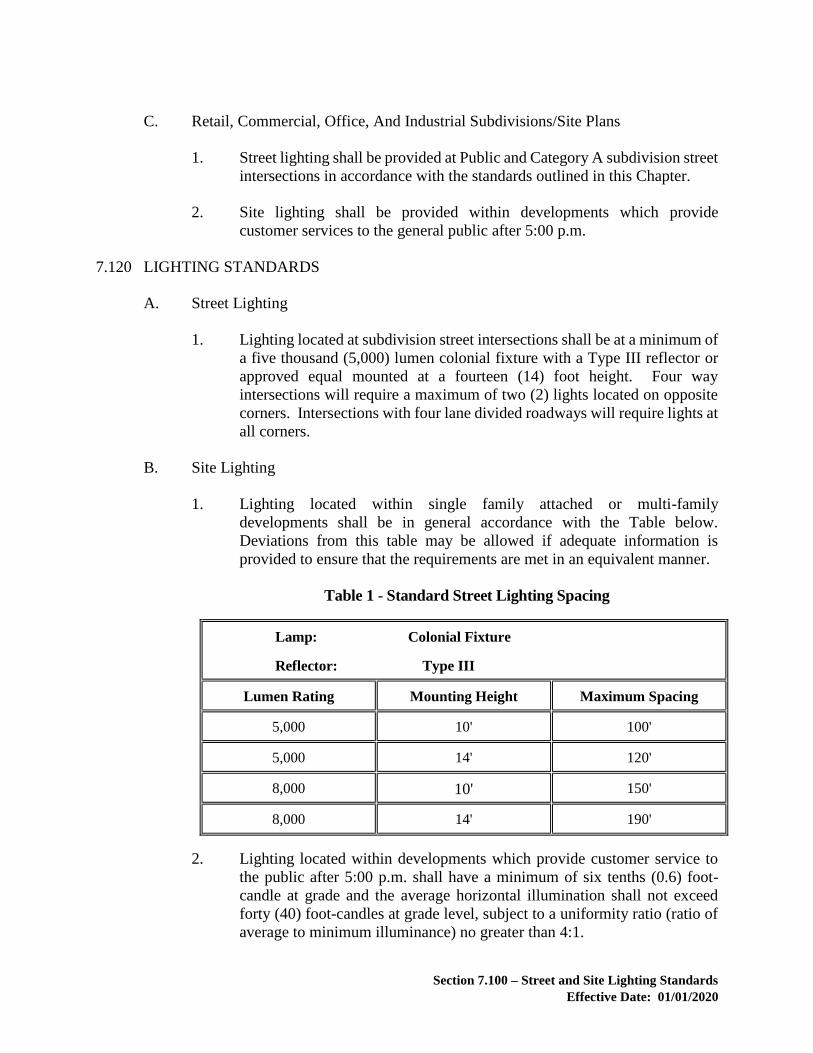
Section 7.100 – Street and Site Lighting Standards
Effective Date: 01/01/2020
C. Retail, Commercial, Office, And Industrial Subdivisions/Site Plans
1. Street lighting shall be provided at Public and Category A subdivision street
intersections in accordance with the standards outlined in this Chapter.
2. Site lighting shall be provided within developments which provide
customer services to the general public after 5:00 p.m.
7.120 LIGHTING STANDARDS
A. Street Lighting
1. Lighting located at subdivision street intersections shall be at a minimum of
a five thousand (5,000) lumen colonial fixture with a Type III reflector or
approved equal mounted at a fourteen (14) foot height. Four way
intersections will require a maximum of two (2) lights located on opposite
corners. Intersections with four lane divided roadways will require lights at
all corners.
B. Site Lighting
1. Lighting located within single family attached or multi-family
developments shall be in general accordance with the Table below.
Deviations from this table may be allowed if adequate information is
provided to ensure that the requirements are met in an equivalent manner.
Table 1 - Standard Street Lighting Spacing
Lamp: Colonial Fixture
Reflector: Type III
Lumen Rating Mounting Height Maximum Spacing
5,000 10' 100'
5,000 14' 120'
8,000 10' 150'
8,000 14' 190'
2. Lighting located within developments which provide customer service to
the public after 5:00 p.m. shall have a minimum of six tenths (0.6) foot-
candle at grade and the average horizontal illumination shall not exceed
forty (40) foot-candles at grade level, subject to a uniformity ratio (ratio of
average to minimum illuminance) no greater than 4:1.

Section 7.100 – Street and Site Lighting Standards
Effective Date: 01/01/2020
7.130 OPERATIONAL, MAINTENANCE, AND INSTALLATION COSTS
A. Operation and maintenance costs of the lighting system will not be the
responsibility of Loudoun County.
B. The recordation documents of the subdivision will indicate that the operational and
maintenance costs are not the public responsibility, and will further designate the
party with whom these responsibilities will ultimately lie.
C. Where the proposed system lies within or adjacent to dedicated public street right-
of-way, the Virginia Department of Transportation requires that such operation,
maintenance, and installation can only be contracted through public utilities or
Loudoun County. The developer or responsible party shall sign an agreement with
the public utility which guarantees full payment to the public utility of all associated
charges, as well as all administrative costs experienced by the public utility. Said
agreement shall be executed prior to Performance Bond release.
D. When VDOT requests the installation of street lights within publicly maintained
street right-of-way concurrent with the land development application process of
Loudoun County, VDOT shall be obligated for the future operation and
maintenance costs arising after the acceptance into the State system.

Section 7.200 – Reserved
Effective Date: 01/01/2020
7.200 RESERVED

Section 7.300 – Tree Conservation
Effective Date: 01/01/2020
7.300 TREE CONSERVATION
A. The County recommends that the following be considered priorities for tree
conservation:
1. Trees, shrubs, and plants located within the Floodplain Overlay District;
2. Intermittent and perennial stream buffers, non-tidal wetlands, and steep
slope areas;
3. Contiguous forest that connects the largest undeveloped or most vegetated
tracts of land within and adjacent to the site;
4. Trees, shrubs, or plants determined to be rare, threatened, or endangered
under the federal Endangered Species Act and those species identified by
the Virginia Department of Game and Inland Fisheries;
5. Trees that are identified as part of a registered historic site;
6. Hedgerows/Fencerows; and
7. Invigorated, healthy, structurally sound trees having a diameter measured
at four and a half (4.5) feet above the ground of thirty (30) inches or more.
B. Conservation of Existing Trees and Vegetation to Meet Canopy and Buffer
Requirements:
1. Existing tree canopy and vegetation, including those areas of tree canopy
and vegetation that an Applicant has agreed to preserve or conserve as part
of a proffer or condition of approval, may be used to meet canopy and/or
buffering and screening requirements of the Zoning Ordinance, if the
following requirements are met:
a. The following shall not be used to meet canopy or buffering and
screening requirements:
i. Concentrated stands of Virginia Pine.
ii. Concentrated stands of invasive plant species as identified
on the Virginia Department of Conservation and Recreation,
Virginia Invasive Plant Species List.
iii. Existing tree canopy and vegetation located within the PRZ,
as defined in Section 7.303.
iv. Existing tree canopy and vegetation, located on residential
lots of twenty thousand (20,000) square feet or less.

Section 7.300 – Tree Conservation
Effective Date: 01/01/2020
b. Existing tree canopy shall meet the standards of desirability and life-
year expectancy established by the Zoning Administrator. Existing
vegetation shall be suitable to provide buffering and screening in
accordance with the requirements of the Zoning Ordinance. To
demonstrate that these requirements are met, a field inspection of
the existing tree canopy and vegetation proposed to be used to meet
the canopy and/or buffering and screening requirements of the
Zoning Ordinance shall be conducted, and a narrative prepared, by
a Certified Arborist, Urban Forester, or Landscape Architect. The
date of the inspection and the name of the individual who conducted
the inspection shall be identified in the narrative.
The narrative may be accompanied by photographs. The narrative
shall describe the overall size, species and general conditions of the
area where such existing trees and vegetation are located. General
conditions include factors such as dominant species, growth rate,
stocking/basal area, structure, form and quality characteristics,
regeneration, age range, soils, aspect, stand history, invasive
species, and hazard trees. The narrative shall also inventory by field
location, common name, scientific name and International Society
of Arboriculture (ISA) condition rating of all trees within the area
of trees and vegetation to be preserved or conserved located within
fifty (50) feet of the limits of clearing and grading that have a
diameter breast height (d.b.h.) of thirty (30) inches or more.
C. Conservation of Existing Trees and Vegetation for Use as Best Management
Practices (BMP):
1. A field inspection shall be conducted, and a narrative prepared, by a
Certified Arborist, Urban Forester, or Landscape Architect. The date of the
inspection and the name of the individual who conducted the inspection
shall be identified in the narrative.
2. The narrative may be accompanied by photographs and shall describe the
overall size, species and general condition of the conserved area where the
existing trees and vegetation are located to demonstrate compliance with
the BMP requirements of Chapter 5 of this Manual. General conditions
include factors such as dominant species, growth rate, stocking/basal area,
structure, form and quality characteristics, regeneration, age range, soils,
aspect, stand history, invasive species, and hazard trees.
3. Existing tree canopy and vegetation used as BMPs in accordance with
Chapter 5 of this Manual shall be located within an easement dedicated to
the County of Loudoun.

Section 7.300 – Tree Conservation
Effective Date: 01/01/2020
7.301 LANDSCAPE PLANTINGS
The County recommends that tree and shrub plantings be native and have multiple values
such as biomass, nuts, fruits, browse, nesting, and aesthetics. Table 3 (Trees and Shrubs)
provides a list of the species that may be used to meet the requirements of Sections 7.302
and 7.305. The Director or Director’s Designee may approve the use of additional species
not listed in Table 3 if such species demonstrate the values listed above. The Director or
Director’s Designee shall establish the minimum planting area (square feet) and canopy
coverage provided (square feet), if applicable, for any approved additional species.
7.302 TREE CONSERVATION AND LANDSCAPE PLANS
When new plantings or existing tree canopy and vegetation are used to satisfy the
requirements of the Zoning Ordinance, this Manual, a proffer, or a condition of approval
of a special exception or variance, an applicant shall submit a Tree Conservation and
Landscape Plan.
A. The Tree Conservation and Landscape Plan shall be overlain upon the site plan or
construction plans and profiles, whichever is applicable, to illustrate the following:
1. Accurate location and species of each planting.
2. No plantings are proposed that would be detrimental to the purpose of sight
distance easements or other easements.
3. Required landscape buffers.
4. Areas of existing tree canopy and vegetation to be preserved or conserved.
5. All tree protection measures required by Section 7.303 of this Chapter.
6. Tree canopy calculations.
7. Landscape planting schedule.
8. Any narrative required by Section 7.300 of this Chapter.
9. References to the appropriate guidelines for planting and maintenance of
new plant material provided by Landscape Contractors Association's;
Landscape Specifications Guidelines for Baltimore - Washington
Metropolitan Area.

Section 7.300 – Tree Conservation
Effective Date: 01/01/2020
a. Above-ground landscape containers and planters for trees shall be
designed in accordance with Virginia Cooperation Extension
publication 430-023, Trees for Landscape Containers and Planters.
b. All planting areas shall contain soils suitable for planting. Soils
shall be free of construction materials. Excessive rock and gravel or
compaction shall be addressed prior to installation of landscape
material.
B. For new plantings used to meet canopy, landscaping and/or buffering and screening
requirements, a Landscape Table shall be provided as follows below. For tree
plantings, canopy coverage provided shall be in accordance with Table 3, or as
established by the Director or Director’s designee for additional species. To
achieve diversity:
1. If 40 or more trees of a planting category are required to be planted, then no
more than one-fourth of any category of trees (large deciduous, small
deciduous, and evergreen) shall be composed of one species.
“SAMPLE” LANDSCAPE TABLE
KEY SCIENTIFIC
NAME
COMMON
NAME
SIZE
(CALIPER
or
HEIGHT)
TYPE OF
ROOT
STOCK
TO BE
PLANTED
*1
QUANTITY _____-YEAR
CANOPY
COVERAGE
PROVIDED
PER TREE
TOTAL
CANOPY
COVERAGE
PROVIDED
Large Deciduous Trees
Ar Acer rubrum Red Maple 2"
caliper B&B
15 270 4,050
Ls Liquidambar
styraciflua
Sweetgum 2"
caliper B&B
15 270 4,050
Qp Quercus palustris Pin Oak
2"
caliper B&B
15 270 4,050
Zs Zelkova serrata Japanese
Zelkova
2” caliper B&B
15 270 4,050
Total 60 16,200

Section 7.300 – Tree Conservation
Effective Date: 01/01/2020
Small Deciduous Trees
Cf Cornus florida Flowering
Dogwood
1” caliper B&B 18 115 2,070
Cc Cercis
canadensis
Redbud 1” caliper B&B 18 115 2,070
Aa Amelanchier
arborea
Downy
Serviceberry
1” caliper B&B 18 115 2,070
Li Lagerstroemia
idica
Common
Crapemyrtle
1” caliper B&B 18 115 2,070
Total 72 8,280
Evergreen Trees
Pa Picea abies Norway Spruce 6’ CON 20 190 3,800
Ps Pinus strobus Eastern White
Pine
6’ CON
20 190 3,800
Io Ilex opaca American
Holly
6’ CON
20 115 2,300
Mg Magnolia
grandiflora
Southern
Magnolia
6’ CON
20 190 3,800
Total 80 13,700
Total
Canopy
212 38,130
Shrubs
Ra Rhododendron
atlantica
Dwarf Azalea 3 gallon CON
20 0 0
As Alnus serrulata Common Alder 3 gallon CON 10 0
Co Cephalanthus
occidentalus
Buttonbush 3 gallon CON
18 0 0
Ca Cornus amomum Silky Dogwood 3 gallon CON 15 0 0
Total 63
Note: Substitute plantings may be permitted in accordance with Chapter 7 of the FSM.
Footnotes:
*1 Type of Root Stock to be planted shall be specified as follows:
balled and burlapped = B&B

Section 7.300 – Tree Conservation
Effective Date: 01/01/2020
bare root = BR
container = CON
C. The use of deciduous trees, evergreen trees, shrubs, ornamental grasses and
perennials, or a combination of these plant types only, shall be used to achieve the
required buffer planting units. Buffer tables shall be provided as follows below.
“SAMPLE” ROAD CORRIDOR BUFFER TABLE
Adjacent Road Name and Type “Road Name” (Major Collector)
Road Corridor Buffer Type
Required
Type 2
Plant Units Per 100 Linear Feet 60
Total Linear Feet 300
Total Required Plant Units 180
Plant Types Quantity Plant Unit
Equivalents
Plant
Units
Percentage
Large
Deciduous
6 10 Plant Units =
1 Plant
60 33%
Evergreen 0 6 Plant Units =
1 Plant
0 0%
Small
Deciduous
12 5 Plant Units =
1 Plant
60 33%
Shrubs 25 2 Plant Units =
1 Plant
50 28%
Ornamental
Grasses
0 1 Plant Unit =
1 Plant
0 0%
Perennials 40 0.25 Plant Unit =
1 Plant
10 6%
Total N/A N/A 180 N/A

Section 7.300 – Tree Conservation
Effective Date: 01/01/2020
“SAMPLE” BUFFER YARD TABLE
Proposed Land Use Group 10
Adjacent Land Use Group 2
Use Buffer Type Required Type B
Plant Units Per 100 Linear Feet 80
Total Linear Feet 350
Total Required Plant Units 280
Plant Types Quantity Plant Unit
Equivalents
Plant
Units
Percentage
Large
Deciduous
8 10 Plant Units =
1 Plant
80 29%
Evergreen 5 6 Plant Units =
1 Plant
30 11%
Small
Deciduous
10 5 Plant Units =
1 Plant
50 18%
Shrubs 40 2 Plant Units =
1 Plant
80 29%
Ornamental
Grasses
20 1 Plant Unit =
1 Plant
20 7%
Perennials 80 0.25 Plant Unit =
1 Plant
20 7%
Total N/A N/A 280 N/A
D. For existing trees, canopy coverage provided shall be determined as follows:
1. For groups of trees, the area of canopy coverage provided shall only include
canopy that meet the requirements of Section 7.300.

Section 7.300 – Tree Conservation
Effective Date: 01/01/2020
2. For individual trees, canopy coverage provided shall be equal to the area of
the CRZ, as defined in Section 7.303.
E. Total canopy coverage calculations shall be provided in tabular form as follows:
“SAMPLE” CANOPY COVERAGE CALCULATIONS
Acreage sq. ft.
Gross Site Area 200 8,712,000
Less Exclusion Areas per Zoning Ordinance 5 217,800
Net Site Area 195 8,494,200
Canopy Coverage Required (10% ) 19.5 849,420
Canopy Coverage Provided
Existing Canopy
Proposed Canopy on Lots - (excluding
Street Trees)
Proposed Canopy – Open Space
Proposed Canopy – Street Trees
Proposed Canopy – Buffers
Reforestation
21
12
1
5
2
1
0
914,760
522,720
43,560
217,800
87,120
43,560
0
Total Canopy Coverage Provided 21 914,760
Requirement is met . . . 914,760 sq. ft. is greater than 849,420 sq. ft.
F. At the time of planting, the applicant may submit a written request to the Director
or Director’s designee to approve the substitution of a species shown on the
approved Landscape Plan with a species from the same planting category in Table
3.
7.303 TREE PROTECTION
Tree protection measures during land disturbing activities shall be in accordance with the
Virginia Erosion and Sediment Control Handbook. Additionally, the following shall
apply:

Section 7.300 – Tree Conservation
Effective Date: 01/01/2020
A. Areas of existing tree canopy and vegetation that an applicant has agreed to
conserve or preserve as part of a proffer or condition of approval or to meet canopy
and/or buffering and screening requirements shall be protected during construction.
B. Critical Root Zone/Protected Root Zone
When areas of existing tree canopy and vegetation that an Applicant has agreed to
preserve or conserve as part of a proffer or condition of approval or to meet canopy
and landscape buffer requirements are identified on a site plan or construction plans
and profiles, the corresponding critical root zone (CRZ) or protected root zone
(PRZ), as applicable, shall be delineated on the site plan and construction plans and
profiles, as well as any grading plan prepared in association with and/or any grading
permit application accompanying said site plan or construction plans and profiles.
1. For individual trees, the CRZ shall be represented by a concentric circle
centered on the tree trunk with a radius equal in feet to one (1) times the
number of inches of the trunk diameter (i.e., The CRZ for a twenty (20) inch
diameter tree is twenty (20) feet), as shown in Figure 1.
2. For groups of trees, the PRZ shall be represented by a line drawn within the
area of tree canopy and vegetation to be preserved or conserved that is
parallel to and 15 feet from the limits of clearing and grading, as shown in
Figure 1.

Section 7.300 – Tree Conservation
Effective Date: 01/01/2020
Figure 1 - Critical Root Zone/Protected Root Zone
FIGURE 1 Section 7.303
(NOT TO SCALE)

Section 7.300 – Tree Conservation
Effective Date: 01/01/2020
C. General Requirements
1. Prior to any land disturbance, protective barriers, such as Super Silt Fence
as shown in Figure 3, or welded wire fence as shown in Figure 6, shall be
installed along the CRZ of any tree, or along the limits of clearing and
grading of any group of trees, as applicable, to be preserved. Protective
barriers shall remain so installed throughout all phases of construction. No
grade changes or storage of equipment, materials, debris, or fill shall be
allowed within the area protected by the barrier. No construction traffic,
parking of vehicles, or disposal of liquids is permitted within the CRZ and
PRZ. All protective barriers are recommended to display tree protection
signage, as shown in Figure 2, installed at a minimum of one sign every
fifty (50) feet.
2. Tree roots which must be severed shall be cut by a trencher or similar
equipment aligned radially to the tree. This method reduces the lateral
movement of the roots during excavation, which if done by other methods
could damage the intertwined roots of adjacent trees. This effort shall take
place and be complete prior to any land disturbance activities.
3. Within four hours of any severance of roots, all tree roots that have been
exposed and/or damaged shall be trimmed cleanly and covered temporarily
with moist peat moss, moist burlap, or other moist biodegradable material
to keep them from drying out until permanent cover can be installed.
4. Prior to completion of Phase 1 erosion and sediment control construction
activity, hazard trees shall be identified by an Urban Forester, Certified
Arborist, or Landscape Architect, marked with paint, saw cut, and removed.
Trees that become hazard trees following Phase 1 erosion and sediment
control construction activity shall also be marked with paint, saw cut, and
removed prior to bond release. Tree stumps located within areas of existing
canopy and vegetation to be preserved or conserved on open space parcels
shall be left intact.
5. Slopes abutting a CRZ or PRZ shall not have a grade greater steeper than
2:1 for a distance of five (5) feet outside the CRZ or PRZ, or a retaining
wall shall be required. Any wall constructed within five (5) feet of the CRZ
or PRZ shall be reviewed and approved by the County Urban Forester or
Director’s designee. Grade changes and excavations shall not encroach
within the CRZ or PRZ, unless approved by the County Urban Forester or
Director’s designee.
6. No toxic materials, including petroleum products, shall be stored within 100
feet of the CRZ or PRZ.
7. Sediment, retention, and detention basins shall not be located within the
CRZ or PRZ. Such basins shall not discharge directly into the CRZ or PRZ

Section 7.300 – Tree Conservation
Effective Date: 01/01/2020
unless the discharge is transitioned back to sheet flow prior to entering the
CRZ or PRZ or is discharged into an adequate natural channel, in
accordance with Chapter 5 of this manual.
D. Pruning Methods
All final cuts shall be made sufficiently close to the trunk or parent limb but without
cutting into the branch collar or leaving a protruding stub, according to the
American National Standards Institute (A300 (Part 1) – Pruning). All necessary
pruning cuts must be made to prevent bark from being torn from the tree and to
facilitate rapid healing. Flush cuts are unacceptable.

Section 7.300 – Tree Conservation
Effective Date: 01/01/2020
Figure 6 - Tree Protective Barrier Detail
Tree Protective Barrier Detail
Welded Wire Fence
FIGURE 6 Section 7.303

Section 7.300 – Tree Conservation
Effective Date: 01/01/2020
Figure 2 - Typical Tree Protection Signage
11” min.
(1) Each such sign shall be made of weather resistant
material, with dimensions of at least eight and one
half by eleven inches.
(2) Each such sign shall show red letters on a white
background.
(3) Signs shall be attached to the protective barriers,
such as Super Silt Fence or welded wire fence, or
shall be securely mounted five feet from grade level
to the bottom of the sign located within one foot of
the protective barrier. Signs shall not be nailed or
attached in any manner to the trees or vegetation to be
preserved.
FIGURE 2 Section 7.303
8.5” min.
Grade Level
KEEP OUT TREE
PROTECTION
AREA
NO ENTRE AREA DE
PROTECCION
DE ARBOLES
5’-0” (for signs not attached to protective barriers)
Typical Tree Protection Signage

Section 7.300 – Tree Conservation
Effective Date: 01/01/2020
7.304 FOREST MANAGEMENT PLAN
Prior to timber harvesting or silvicultural activities, a Forest Management Plan (FMP),
when required by the Zoning Ordinance for the Floodplain Overlay District, Mountainside
Development Overlay District, Limestone Overlay District, and Steep Slope Standards,
shall be required and submitted to the Director or Director’s designee for approval. The
approved FMP is required to be on file with the Director or Director’s designee and a copy
kept on site throughout the duration of the timber harvest or silvicultural activity, including
site stabilization, where applicable.
A. A meeting with the Director or Director’s designee is recommended to discuss the
scope of the proposed timber harvest or silvicultural activities prior to the
preparation and submission of the FMP.
B. The purpose of the FMP is to establish the tract location and to describe the Best
Management Practices (BMP’s) required for structural stabilization and re-
vegetation of all exposed mineral soil sites. The FMP shall be prepared by the
Virginia Department of Forestry, or a professional forester with, at a minimum, a
Bachelor of Science degree from and accredited School of Forestry, and shall
contain the following information:
1. Sheet size of 11 inches x 17 inches with a scale large enough to clearly
depict tract boundaries, timber type lines, water bodies, topography and
acreage to be harvested. These maps are available through the Loudoun
County Office of Mapping and Geographic Information.
2. Identify all streams, their headwaters and a Streamside Management Zone
(SMZ) at least fifty (50) feet wide on either side of the stream.
3. Approximate location of all decks, haul roads, primary skid trails, and any
other road, trail, or travelway that will be used for the timber harvest or
silvicultural activity.
4. If grading, including excavation or filling, is necessary for deck or haul road
construction, or construction of any other road, trail, or travelway that will
be used for the timber harvest or silvicultural activity, a detailed map
showing location, topography and information addressing stabilization.
5. Identify species composition, stocking, regeneration, soils, stand history,
unique natural features, percent slope, quality and growth rate, and
approximate stems per acre to be harvested.
6. Harvest type (i.e., selective, shelterwood, diameter limit cut, clear-cut, etc.)
7. Means of regeneration (natural or artificial).
8. Means of post-harvest closure and stabilization, as applicable.

Section 7.300 – Tree Conservation
Effective Date: 01/01/2020
9. Recommendations regarding the viability of a fuel wood harvest.
10. Statement that all BMP’s shall be in accordance with the Virginia
Department of Forestry Best Management Practices for Water Quality and
all post-harvest BMP’s shall be implemented immediately upon logging
completion.
11. Plan shall be signed by the drafting professional forester.
C. The following notification shall be provided:
1. Notification pursuant to Section 10.1-1181.2 (H) of the Code of Virginia
[“Notification of Commercial Harvesting of Timber” (800/939-LOGS)].
2. A call to the County Urban Forester or Director’s designee at least twenty-
four (24) hours prior to commencement of the logging operation.
3. A call to the County Urban Forester or Director’s designee immediately
upon installation of all BMP's.
7.305 REFORESTATION STANDARDS
Any required reforestation used to satisfy the Zoning Ordinance, a proffer, or a condition
of approval of a special exception or variance shall comply with the following standards.
These standards may serve as guidance for other voluntary planting efforts.
A planting plan prepared by an Urban Forester, Certified Arborist, or Landscape Architect
shall be required and shall be reviewed and approved by the County Urban Forester or
Director’s Designee. The planting plan shall specifically address plant materials, plant
density/stocking requirements, site preparation, site stabilization, release/maintenance,
livestock exclusion, wildlife damage, maintenance, and restocking requirements (post-
establishment) in accordance with the Natural Resources Conservation Service Tree and
Shrub Establishment Guidelines and the Virginia Department of Forestry Hardwood
Management: Planting Guidelines. Tree plantings shall be native and have multiple use
benefits that improve or enhance wildlife, recreation, and overall aesthetic values and shall
consist primarily of pioneer (early succession) tree species. Any proposed streambank
stabilization and control of invasive plant species also should be addressed by the planting
plan.
A. Plant Materials
A general description of the existing trees and vegetation on the site shall be
provided. To achieve diversity, large deciduous tree plantings shall consist of a
mixture of five (5) or more species from Table 3 and small deciduous and evergreen
tree plantings shall consist of a mixture of three (3) or more species from Table 3.
The County Urban Forester or Director’s Designee may approve the use of
additional tree species where appropriate.

Section 7.300 – Tree Conservation
Effective Date: 01/01/2020
1. Plantings should be installed in early Spring (March–April) or Fall
(October-November).
B. Planting Density/Stocking Requirements
1. Plantings shall be installed in accordance with one of the plant density
options listed in Table 2. The County Urban Forester or Director’s designee
may allow the use of existing native vegetation to meet the plants per acre
requirement.
Table 2 - Required Plant Densities for Reforestation
Plant Size Plants per Acre Plant Spacing (ft)
Option 1: Seedlings
Large Deciduous Trees
Small Deciduous Trees and/or
Evergreen Trees
350
85
10’ x 10’
Tree plantings shall
be evenly distributed
with evergreens
and/or small
deciduous trees
interspersed between
the large deciduous
trees.
Option 2: Container (3-gallon or larger) or
Balled and Burlapped
Large Deciduous Trees
Small Deciduous Trees and/or
Evergreen Trees
240
60
12’ x 12’
Tree plantings shall
be evenly distributed
with evergreens
and/or small
deciduous trees
interspersed between
the large deciduous
trees.
2. Planting Tubes. Protect all seedlings with four (4)-foot high protective,
biodegradable tree shelters.
3. Buck Rub Protection. Protect each container or balled and burlapped tree
with a wire cage one (1) foot in diameter and a minimum of forty-eight (48)
inches tall secured with a two-inch by two-inch (2” x 2”) oak stake.

Section 7.300 – Tree Conservation
Effective Date: 01/01/2020
C. Release/Maintenance
Newly installed plant material shall be periodically maintained to ensure release for
up to two (2) years after planting.
D. Restocking Requirements (Post-Establishment)
If a targeted stocking of seventy-five percent (75%) survival with uniform
distribution is not achieved within two (2) years of planting as determined by the
County Urban Forester or Director’s designee, the Applicant shall provide a one-
time supplemental planting to achieve the full, initial stocking.

Section 7.300 – Tree Conservation
Effective Date: 01/01/2020
Table 3 - Trees and Shrubs
Planting Category – Large Deciduous The Uses column identifies certain species that may be better suited for planting in Parking Lots and underneath
overhead Utility Lines. Gateway Corridor Buffer Yards shall be planted with species specified for Gateway Corridor.
Botanical Name Common Name
Min
imu
m
Pla
nti
ng
Are
a i
n s
q.
ft.
N:
Na
tiv
e
PL
: P
ark
ing L
ot
U:
U
tili
ty L
ines
GC
: G
ate
wa
y C
orr
ido
r
Canopy
Coverage
(sq. ft.)
Per Caliper
10 Year
Canopy
Coverage
(sq. ft.)
Per Caliper
20 Year
Uses 1.0" 2.0" 3.0" 1.0" 2.0" 3.0"
Acer rubrum
'Columnare'
Columnar Red
Maple 55 PL 45 55 75 70 75 90
Carpinus betulus
'Fastigiata'
Fastigiate
European
Hornbeam
55 45 55 75 70 75 90
Fagus sylvatica
'Fastigiata'
Fastigiate
European
Beech
55 GC 45 55 75 70 75 90
Gingko biloba
'Princeton Sentry'
Princeton Sentry
Gingko 55 45 55 75 70 75 90
Quercus robur
'Fastigiata'
Fastigiate English
Oak 55 PL 45 55 75 70 75 90
Aesculus flava Yellow Buckeye 90 N GC 130 150 175 195 205 210
Aesculua glabra Ohio Buckeye 90 130 150 175 195 205 210
Aesculus
hippocastanum
Common
Horsechestnut 90 GC 130 150 175 195 205 210
Betula
alleghaniensis Yellow Birch 90 N 130 150 175 195 205 210
Betula lenta Black Birch 90 N GC 130 150 175 195 205 210
Betula nigra River Birch 90 N GC 130 150 175 195 205 210
Castanea mollissima Chinese Chestnut 90 130 150 175 195 205 210
Celtis occidentalis Common
Hackberry 90 N GC 130 150 175 195 205 210
Cercidiphyllum
japonicum Katsuratree 90 PL 130 150 175 195 205 210
Cladrastis lutea Yellowwood 90 N PL 130 150 175 195 205 210
Diospyros virginiana Common
Persimmon 90 N GC 130 150 175 195 205 210
Eucommia ulmoides Hardy Rubber Tree 90 PL 130 150 175 195 205 210
Fagus sylvatica European Beech 90 130 150 175 195 205 210

Section 7.300 – Tree Conservation
Effective Date: 01/01/2020
Planting Category – Large Deciduous The Uses column identifies certain species that may be better suited for planting in Parking Lots and underneath
overhead Utility Lines. Gateway Corridor Buffer Yards shall be planted with species specified for Gateway Corridor.
Botanical Name Common Name
Min
imu
m
Pla
nti
ng
Are
a i
n s
q.
ft.
N:
Na
tiv
e
PL
: P
ark
ing L
ot
U:
U
tili
ty L
ines
GC
: G
ate
wa
y C
orr
ido
r
Canopy
Coverage
(sq. ft.)
Per Caliper
10 Year
Canopy
Coverage
(sq. ft.)
Per Caliper
20 Year
Uses 1.0" 2.0" 3.0" 1.0" 2.0" 3.0"
Gleditsia triacanthos
var. inermis (Identify Specific 'Cultivar')
Thornless
Common
Honeylocust
90 N PL, GC 130 150 175 195 205 210
Gymnocladus
dioicus
Kentucky
Coffeetree 90 PL 130 150 175 195 205 210
Juglans cinerea Butternut 90 N 130 150 175 195 205 210
Maclura pomifera Osage-Orange 90 N 130 150 175 195 205 210
Magnolia acuminata Cucumbertree
Magnolia 90 N 130 150 175 195 205 210
Magnolia
macrophylla Bigleaf Magnolia 90 N 130 150 175 195 205 210
Metasequoia
glyptostroboides Dawn Redwood 90 130 150 175 195 205 210
Nyssa aquatica Water Tupelo 90 N 130 150 175 195 205 210
Nyssa sylvatica Black Gum 90 N PL, GC 130 150 175 195 205 210
Ostrya virginiana Eastern
Hophornbeam 90 N GC 130 150 175 195 205 210
Pistacia chinensis Chinese Pistache 90 PL 130 150 175 195 205 210
Prunus pensylvanica Pin Cherry 90 N 130 150 175 195 205 210
Prunus sargentii Sargent Cherry 90 130 150 175 195 205 210
Prunus serotina Wild Black Cherry 90 N GC 130 150 175 195 205 210
Prunus serrulata
'Kwanzan'
'Kwanzan'
Japanese
Flowering Cherry
90 130 150 175 195 205 210
Prunus subhirtella
var. pendula
Weeping Higan
Cherry 90 130 150 175 195 205 210
Prunus x yedoensis Yoshino Cherry 90 130 150 175 195 205 210
Quercus
hemisphaerica Laurel Oak 90 N 130 150 175 195 205 210
Quercus ilicifolia Bear Oak 90 N 130 150 175 195 205 210
Quercus lyrata Overcup Oak 90 N 130 150 175 195 205 210

Section 7.300 – Tree Conservation
Effective Date: 01/01/2020
Planting Category – Large Deciduous The Uses column identifies certain species that may be better suited for planting in Parking Lots and underneath
overhead Utility Lines. Gateway Corridor Buffer Yards shall be planted with species specified for Gateway Corridor.
Botanical Name Common Name
Min
imu
m
Pla
nti
ng
Are
a i
n s
q.
ft.
N:
Na
tiv
e
PL
: P
ark
ing L
ot
U:
U
tili
ty L
ines
GC
: G
ate
wa
y C
orr
ido
r
Canopy
Coverage
(sq. ft.)
Per Caliper
10 Year
Canopy
Coverage
(sq. ft.)
Per Caliper
20 Year
Uses 1.0" 2.0" 3.0" 1.0" 2.0" 3.0"
Quercus marilandica Blackjack Oak 90 N 130 150 175 195 205 210
Quercus
muehlenbergii Chinkapin Oak 90 N 130 150 175 195 205 210
Quercus nigra Water Oak 90 N 130 150 175 195 205 210
Quercus stellata Post Oak 90 N 130 150 175 195 205 210
Robinia
pseudoacacia Black Locust 90 N 130 150 175 195 205 210
Salix babylonica Babylon Weeping
Willow 90 130 150 175 195 205 210
Salix nigra Black Willow 90 N GC 130 150 175 195 205 210
Sassafras albidum Sassafras 90 N GC 130 150 175 195 205 210
Taxodium ascendens Pondcypress 90 N PL 130 150 175 195 205 210
Taxodium distichum Common
Baldcypress 90 N GC 130 150 175 195 205 210
Tilia cordata (Identify Specific 'Cultivar')
Littleleaf Linden 90 PL 130 150 175 195 205 210
Tilia tomentosa Silver Linden 90 PL 130 150 175 195 205 210
Acer negundo
Boxelder
(Reforestation
Only)
x N x x x x x x
Acer rubrum Red Maple 130 N PL, GC 150 200 250 225 270 300
Acer saccharinum
Silver Maple
(Reforestation
Only)
x N x x x x x x
Acer saccharum Sugar Maple 130 N GC 150 200 250 225 270 300
Carya cordiformis Bitternut Hickory 130 N GC 150 200 250 225 270 300
Carya glabra Pignut Hickory 130 N GC 150 200 250 225 270 300
Carya illinoinensis Pecan 130 GC 150 200 250 225 270 300
Carya laciniosa Shellbark Hickory 130 N GC 150 200 250 225 270 300

Section 7.300 – Tree Conservation
Effective Date: 01/01/2020
Planting Category – Large Deciduous The Uses column identifies certain species that may be better suited for planting in Parking Lots and underneath
overhead Utility Lines. Gateway Corridor Buffer Yards shall be planted with species specified for Gateway Corridor.
Botanical Name Common Name
Min
imu
m
Pla
nti
ng
Are
a i
n s
q.
ft.
N:
Na
tiv
e
PL
: P
ark
ing L
ot
U:
U
tili
ty L
ines
GC
: G
ate
wa
y C
orr
ido
r
Canopy
Coverage
(sq. ft.)
Per Caliper
10 Year
Canopy
Coverage
(sq. ft.)
Per Caliper
20 Year
Uses 1.0" 2.0" 3.0" 1.0" 2.0" 3.0"
Carya ovata Shagbark Hickory 130 N GC 150 200 250 225 270 300
Carya tomentosa Mockernut
Hickory 130 N GC 150 200 250 225 270 300
Celtis laevigata Sugar Hackberry 130 N 150 200 250 225 270 300
Fagus grandifolia American Beech 130 N GC 150 200 250 225 270 300
Gingko biloba
(male) Gingko 130 PL 150 200 250 225 270 300
Juglans nigra Black Walnut 130 N 150 200 250 225 270 300
Liquidambar
styraciflua
American
Sweetgum 130 N GC 150 200 250 225 270 300
Liriodendron
tulipifera Tuliptree 130 N 150 200 250 225 270 300
Platanus
occidentalis Sycamore 130 N GC 150 200 250 225 270 300
Platanus x acerifolia London Planetree 130 PL, GC 150 200 250 225 270 300
Populus deltoides Cottonwood 130 N GC 150 200 250 225 270 300
Quercus alba White Oak 130 N GC 150 200 250 225 270 300
Quercus bicolor Swamp White Oak 130 N PL, GC 150 200 250 225 270 300
Quercus coccinea Scarlet Oak 130 N PL, GC 150 200 250 225 270 300
Quercus falcata Southern Red Oak 130 N PL, GC 150 200 250 225 270 300
Quercus imbricaria Shingle Oak 130 N 150 200 250 225 270 300
Quercus michauxii Swamp Chestnut
Oak 130 N PL 150 200 250 225 270 300
Quercus montana Chestnut Oak 130 N PL, GC 150 200 250 225 270 300
Quercus palustris Pin Oak 130 N PL, GC 150 200 250 225 270 300
Quercus phellos Willow Oak 130 N PL, GC 150 200 250 225 270 300
Quercus rubra Northern Red Oak 130 N PL, GC 150 200 250 225 270 300
Quercus shumardii Shumard Oak 130 PL, GC 150 200 250 225 270 300

Section 7.300 – Tree Conservation
Effective Date: 01/01/2020
Planting Category – Large Deciduous The Uses column identifies certain species that may be better suited for planting in Parking Lots and underneath
overhead Utility Lines. Gateway Corridor Buffer Yards shall be planted with species specified for Gateway Corridor.
Botanical Name Common Name
Min
imu
m
Pla
nti
ng
Are
a i
n s
q.
ft.
N:
Na
tiv
e
PL
: P
ark
ing L
ot
U:
U
tili
ty L
ines
GC
: G
ate
wa
y C
orr
ido
r
Canopy
Coverage
(sq. ft.)
Per Caliper
10 Year
Canopy
Coverage
(sq. ft.)
Per Caliper
20 Year
Uses 1.0" 2.0" 3.0" 1.0" 2.0" 3.0"
Quercus velutina Black Oak 130 N 150 200 250 225 270 300
Salix matsudana
'Tortuosa' Corkscrew Willow 130 150 200 250 225 270 300
Sophora japonica Japanese
Pagodatree 130 GC 150 200 250 225 270 300
Tilia americana (Identify Specific 'Cultivar')
American Linden
(Basswood) 130 N PL 150 200 250 225 270 300
Ulmus americana American Elm 130 N PL, GC 150 200 250 225 270 300
Ulmus carpinifolia Smoothleaf Elm 130 150 200 250 225 270 300
Ulmus parvifolia Chinese Elm 130 PL, GC 150 200 250 225 270 300
Zelkova serrata Japanese Zelkova 130 PL, U 150 200 250 225 270 300

Section 7.300 – Tree Conservation
Effective Date: 01/01/2020
Planting Category – Small Deciduous The Uses column identifies certain species that may be better suited for planting in Parking Lots and underneath overhead
Utility Lines. Gateway Corridor Buffer Yards shall be planted with species specified for Gateway Corridor.
Botanical Name Common Name
Min
imu
m P
lan
tin
g
Are
a i
n s
q.
ft.
N:
Na
tiv
e
PL
: P
ark
ing L
ot
U:
U
tili
ty L
ines
GC
: G
ate
wa
y C
orr
ido
r
Canopy
Coverage
(sq. ft.)
Per Caliper
10 Year
Canopy
Coverage
(sq. ft.)
Per Caliper
20 Year
Uses 1.0" 2.0" 3.0" 1.0" 2.0" 3.0"
Acer buergerianum Trident Maple 55 GC 75 100 125 115 135 150
Acer campestre Hedge Maple 55 U 75 100 125 115 135 150
Acer ginnala Amur Maple 55 U 75 100 125 115 135 150
Acer griseum Paperbark Maple 55 75 100 125 115 135 150
Acer palmatum Japanese Maple 55 U 75 100 125 115 135 150
Aesculus pavia Red Buckeye 55 PL 75 100 125 115 135 150
Amelanchier arborea Downy
Serviceberry 55 N U 75 100 125 115 135 150
Amelanchier
canadensis
Shadblow
Serviceberry 55 N U, GC 75 100 125 115 135 150
Amelanchier laevis Allegheny
Serviceberry 55 N U, GC 75 100 125 115 135 150
Asimina triloba Common Pawpaw 55 N GC 75 100 125 115 135 150
Betula populifolia Gray Birch 55 75 100 125 115 135 150
Carpinus caroliniana American
Hornbeam 55 N GC 75 100 125 115 135 150
Castanea pumila Allegheny
Chinkapin 55 N GC 75 100 125 115 135 150
Cercis canadensis Redbud 55 N U, GC 75 100 125 115 135 150
Chionanthus
virginicus White Fringetree 55 N U 75 100 125 115 135 150
Cornus alternifolia Pagoda Dogwood 55 N 75 100 125 115 135 150
Cornus florida Flowering
Dogwood 55 N U 75 100 125 115 135 150
Cornus kousa Kousa Dogwood 55 U, GC 75 100 125 115 135 150
Crataegus coccinea Scarlet Hawthorn 55
75 100 125 115 135 150
Crataegus crusgalli Cockspur
Hawthorn 55 N 75 100 125 115 135 150

Section 7.300 – Tree Conservation
Effective Date: 01/01/2020
Planting Category – Small Deciduous The Uses column identifies certain species that may be better suited for planting in Parking Lots and underneath overhead
Utility Lines. Gateway Corridor Buffer Yards shall be planted with species specified for Gateway Corridor.
Botanical Name Common Name
Min
imu
m P
lan
tin
g
Are
a i
n s
q.
ft.
N:
Na
tiv
e
PL
: P
ark
ing L
ot
U:
U
tili
ty L
ines
GC
: G
ate
wa
y C
orr
ido
r
Canopy
Coverage
(sq. ft.)
Per Caliper
10 Year
Canopy
Coverage
(sq. ft.)
Per Caliper
20 Year
Uses 1.0" 2.0" 3.0" 1.0" 2.0" 3.0"
Crataegus
phaenopyrum
Washington
Hawthorn 55 N U 75 100 125 115 135 150
Crataegus viridus Winter King
Hawthorn 55 GC 75 100 125 115 135 150
Franklinia
alatamaha Franklinia 55 N 75 100 125 115 135 150
Halesia diptera Two-Winged
Silverbell 55 N GC 75 100 125 115 135 150
Halesia tetraptera Carolina Silverbell 55 N GC 75 100 125 115 135 150
Hamamelis
virginiana Witchhazel 55 N U, GC 75 100 125 115 135 150
Koelreuteria
paniculata
Panicled
Goldenraintree 55 GC 75 100 125 115 135 150
Laburnum x. wateri Golden Chain 55 75 100 125 115 135 150
Lagerstroemia spp. (Identify Species &
'Cultivar') Crape Myrtle 55 U 75 100 125 115 135 150
Magnolia x
soulangeana Saucer Magnolia 55 75 100 125 115 135 150
Magnolia stellata Star Magnolia 55 U 75 100 125 115 135 150
Magnolia virginiana Sweetbay
Magnolia 55 N U, GC 75 100 125 115 135 150
Malus spp. Crabapple 55 U 75 100 125 115 135 150
Morus rubra Red Mulberry 55 N 75 100 125 115 135 150
Oxydendrum
arboreum Sourwood 55 N GC 75 100 125 115 135 150
Persea borbonia Redbay Sweetbay 55 N 75 100 125 115 135 150
Prunus americana American Wild
Plum 55 N 75
1
00 125 115 135 150
Prunus cerasifera Flowering Plum 55 U 75 100 125 115 135 150
Prunus virginiana Choke Cherry 55 N 75 100 125 115 135 150

Section 7.300 – Tree Conservation
Effective Date: 01/01/2020
Planting Category – Small Deciduous The Uses column identifies certain species that may be better suited for planting in Parking Lots and underneath overhead
Utility Lines. Gateway Corridor Buffer Yards shall be planted with species specified for Gateway Corridor.
Botanical Name Common Name
Min
imu
m P
lan
tin
g
Are
a i
n s
q.
ft.
N:
Na
tiv
e
PL
: P
ark
ing L
ot
U:
U
tili
ty L
ines
GC
: G
ate
wa
y C
orr
ido
r
Canopy
Coverage
(sq. ft.)
Per Caliper
10 Year
Canopy
Coverage
(sq. ft.)
Per Caliper
20 Year
Uses 1.0" 2.0" 3.0" 1.0" 2.0" 3.0"
Prunus x incamp
'Okame' 'Okame' Cherry 55 U 75 100 125 115 135 150
Rhamnus caroliniana Carolina
Buckthorn 55 N 75 100 125 115 135 150
Stewartia koreana Korean Stewartia 55 U 75 100 125 115 135 150
Stewartia ovata Mountain
Stewartia 55 U 75 100 125 115 135 150
Stewartia
pseudocamellia Japanese Stewartia 55 U, GC 75 100 125 115 135 150
Styrax japonicus Japanese Snowbell 55 U, GC 75 100 125 115 135 150
Syringa reticulata Japanese Tree
Lilac 55 U 75 100 125 115 135 150

Section 7.300 – Tree Conservation
Effective Date: 01/01/2020
Planting Category – Evergreen The Uses column identifies certain species that may be better suited for planting underneath overhead Utility Lines.
Gateway Corridor Buffer Yards shall be planted with species specified for Gateway Corridor.
Botanical Name Common Name
Min
imu
m
Pla
nti
ng
Are
a i
n s
q.
ft.
N:
Na
tiv
e
U:
U
tili
ty L
ines
GC
: G
ate
wa
y C
orr
ido
r
Canopy
Coverage
(sq. ft.)
Per Height
10 Year
Canopy
Coverage
(sq. ft.)
Per Height
20 Year
Uses 6.0' 8.0' 10.0' 6.0' 8.0' 10.0'
Ilex x attenuata
'Fosteri' Foster's Holly 35 U, GC 45 55 75 70 75 90
Ilex x 'Nellie R.
Stevens'
Nellie Stevens
Holly 35 U, GC 45 55 75 70 75 90
Juniperus chinensis (Identify Specific 'Cultivar')
Chinese Juniper 35 U 45 55 75 70 75 90
Juniperus virginiana
'Manhattan Blue'
'Princeton Sentry'
Manhattan Blue
Princeton Sentry 35 45 55 75 70 75 90
Taxus baccata English Yew 35 45 55 75 70 75 90
Taxus baccata
'Fastigiata' Upright Irish Yew 35 45 55 75 70 75 90
Thuja occidentalis (Identify Specific 'Cultivar')
Eastern Arborvitae 35 N 45 55 75 70 75 90
Thuja orientalis (Identify Specific 'Cultivar')
Oriental
Arborvitae 35 45 55 75 70 75 90
Abies concolor White Fir 55 75 100 125 115 135 150
Chamaecyparis
lawsoniana
Lawson
Falsecypress 55 75 100 125 115 135 150
Chamaecyparis
obtusa
Hinoki
Falsecypress 55 75 100 125 115 135 150
Chamaecyparis
thyoides
Atlantic White
Cedar 55 N 75 100 125 115 135 150
Cryptomeria
japonica
Japanese
Cryptomeria 55 GC 75 100 125 115 135 150
X Cupressocyparis
leylandii Leyland Cypress 55 75 100 125 115 135 150
Ilex aquifolium English Holly 55 U 75 100 125 115 135 150
Ilex opaca American Holly 55 N U, GC 75 100 125 115 135 150
Juniperus virginiana
Eastern Red Cedar (Do not plant within
900 ft. of commercial
orchards)
55 N GC 75 100 125 115 135 150
Picea glauca White Spruce 55 75 100 125 115 135 150

Section 7.300 – Tree Conservation
Effective Date: 01/01/2020
Planting Category – Evergreen The Uses column identifies certain species that may be better suited for planting underneath overhead Utility Lines.
Gateway Corridor Buffer Yards shall be planted with species specified for Gateway Corridor.
Botanical Name Common Name
Min
imu
m
Pla
nti
ng
Are
a i
n s
q.
ft.
N:
Na
tiv
e
U:
U
tili
ty L
ines
GC
: G
ate
wa
y C
orr
ido
r
Canopy
Coverage
(sq. ft.)
Per Height
10 Year
Canopy
Coverage
(sq. ft.)
Per Height
20 Year
Uses 6.0' 8.0' 10.0' 6.0' 8.0' 10.0'
Picea omorika Serbian Spruce 55 75 100 125 115 135 150
Picea orientalis Oriental Spruce 55 75 100 125 115 135 150
Picea pungens Colorado Spruce 55 75 100 125 115 135 150
Pinus bungeana Lacebark Pine 55 75 100 125 115 135 150
Pinus parviflora Japanese White
Pine 55 75 100 125 115 135 150
Pinus serotina Pond Pine 55 N 75 100 125 115 135 150
Pseudotsuga
menziesii Douglasfir 55 75 100 125 115 135 150
Taxus cuspidata (Identify Specific 'Cultivar')
Japanese Yew 55 75 100 125 115 135 150
Thuja plicata Western
Arborvitae 55 75 100 125 115 135 150
Tsuga canadensis Canadian
Hemlock 55 N 75 100 125 115 135 150
Tsuga caroliniana Carolina Hemlock 55 N 75 100 125 115 135 150
Cedrus atlantica Atlas Cedar 90 125 150 175 190 205 210
Picea abies Norway Spruce 90 GC 125 150 175 190 205 210
Pinus echinata Shortleaf Pine 90 N 125 150 175 190 205 210
Pinus sylvestris Scotch Pine 90 125 150 175 190 205 210
Cedrus deodara Deodar Cedar 110 GC 125 150 175 190 205 210
Magnolia
grandiflora
Southern
Magnolia 110 GC 125 150 175 190 205 210
Pinus rigida Pitch Pine 110 N 125 150 175 190 205 210
Pinus strobus Eastern White
Pine 110 N 125 150 175 190 205 210
Pinus taeda Loblolly Pine 110 N GC 125 150 175 190 205 210
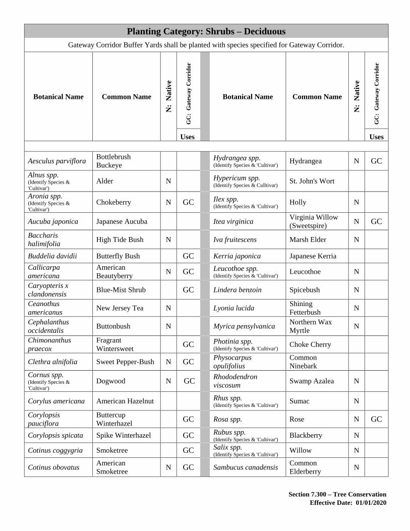
Section 7.300 – Tree Conservation
Effective Date: 01/01/2020
Planting Category: Shrubs – Deciduous
Gateway Corridor Buffer Yards shall be planted with species specified for Gateway Corridor.
Botanical Name Common Name
N:
Na
tiv
e
GC
: G
ate
wa
y C
orr
ido
r
Botanical Name Common Name
N:
Na
tiv
e
GC
: G
ate
wa
y C
orr
ido
r
Uses Uses
Aesculus parviflora Bottlebrush
Buckeye Hydrangea spp.
(Identify Species & 'Cultivar') Hydrangea N GC
Alnus spp. (Identify Species &
'Cultivar') Alder N Hypericum spp.
(Identify Species & Culltivar) St. John's Wort
Aronia spp. (Identify Species &
'Cultivar') Chokeberry N GC Ilex spp.
(Identify Species & 'Cultivar') Holly N
Aucuba japonica Japanese Aucuba Itea virginica Virginia Willow
(Sweetspire) N GC
Baccharis
halimifolia High Tide Bush N Iva fruitescens Marsh Elder N
Buddelia davidii Butterfly Bush GC Kerria japonica Japanese Kerria
Callicarpa
americana
American
Beautyberry N GC Leucothoe spp.
(Identify Species & 'Cultivar') Leucothoe N
Caryopteris x
clandonensis Blue-Mist Shrub GC Lindera benzoin Spicebush N
Ceanothus
americanus New Jersey Tea N Lyonia lucida
Shining
Fetterbush N
Cephalanthus
occidentalis Buttonbush N Myrica pensylvanica
Northern Wax
Myrtle N
Chimonanthus
praecox
Fragrant
Wintersweet GC Photinia spp.
(Identify Species & 'Cultivar') Choke Cherry
Clethra alnifolia Sweet Pepper-Bush N GC Physocarpus
opulifolius
Common
Ninebark
Cornus spp. (Identify Species &
'Cultivar') Dogwood N GC
Rhododendron
viscosum Swamp Azalea N
Corylus americana American Hazelnut Rhus spp. (Identify Species & 'Cultivar')
Sumac N
Corylopsis
pauciflora
Buttercup
Winterhazel GC Rosa spp. Rose N GC
Corylopsis spicata Spike Winterhazel GC Rubus spp. (Identify Species & 'Cultivar')
Blackberry N
Cotinus coggygria Smoketree GC Salix spp. (Identify Species & 'Cultivar')
Willow N
Cotinus obovatus American
Smoketree N GC Sambucus canadensis
Common
Elderberry N

Section 7.300 – Tree Conservation
Effective Date: 01/01/2020
Planting Category: Shrubs – Deciduous
Gateway Corridor Buffer Yards shall be planted with species specified for Gateway Corridor.
Botanical Name Common Name
N:
Na
tiv
e
GC
: G
ate
wa
y C
orr
ido
r
Botanical Name Common Name
N:
Na
tiv
e
GC
: G
ate
wa
y C
orr
ido
r
Uses Uses
Cottoneaster spp Cottoneaster Spirea spp. (Identify Species & 'Cultivar')
Spirea N GC
Crataegus flabellata Fanleaf Hawthorn Stewartia
malacodendron Silky Camelia N
Cyrilla racemiflora Swamp Cyrilla N Styrax americanus American
Snowbell
Deutzia gracilis Deutzia Symphoricarpos
orbiculatus Coral Berry
Euonymus spp. (Identify Species &
'Cultivar') Euonymus N Vaccinium spp.
(Identify Species & 'Cultivar') Vaccinium N
Fothergilla
gardenia Dwarf Fothergilla GC Viburnum spp.
(Identify Species & 'Cultivar') Viburnum N GC
Fothergilla major Fothergilla GC Vitex agnus Chastetree GC
Gaylussacia spp. (Identify Species &
'Cultivar') Huckleberries N

Section 7.300 – Tree Conservation
Effective Date: 01/01/2020
Planting Category: Shrubs – Evergreen
Gateway Corridor Buffer Yards shall be planted with species specified for Gateway Corridor.
Botanical Name Common Name
N:
N
ati
ve
GC
: G
ate
wa
y C
orr
ido
r
Botanical Name Common Name
N:
N
ati
ve
GC
: G
ate
wa
y C
orr
ido
r
Uses Uses
Berberis julianae Wintergreen
Barberry
Osmanthus
heterophyllus Falseholly N
Buxus microphylla Littleleaf Boxwood GC Pieris floribunda Evergreen Mountain
Fetterbush N
Buxus sempervirens Common Boxwood GC Pieris japonica Japanese Pieris
Camellia japonica Japanese Camellia Potentilla fruticosa Cinquefoil
Euonymus spp. (Identify Species & 'Cultivar')
Euonymus Prunus laurocerasus Common Cherry
Laurel GC
Gaultheria
procumbens Wintergreen N
Rhododendron
atlanticum Dwarf Azalea N
Ilex x aquipernyi Dragon Lady Holly Rhododendron
calendulaceum Flame Azalea N
Ilex cornuta Chinese Holly Rhododendron
catawbiense
Catawba
Rhododendron N
Ilex cornuta
'Burfordii' Burford Holly
Rhododendron
cumberlandense
Cumberland Flame
Azalea N
Ilex crenata Japanese Holly Rhododendron
maximum
Great Rhododendron
Rose Bay N
Ilex glabra Inkberry N GC Rhododendron
periclymenoides Pinxter Flower N
Ilex spp. (Identify Species & 'Cultivar')
Holly GC Rhododendron
prinophyllum Rose Azalea N
Ilex vomitoria Yaupon Holly N Rhododendron spp. (Identify Species & 'Cultivar')
Azalea and
Rhododendron
Juniperus spp. (Identify Species & 'Cultivar')
Juniper GC Skimmia japonica Japanese Skimma
Kalmia latifolia Mountain Laurel N GC Taxus baccata English Yew
Mahonia aquifolium Oregon Grapeholly Taxus cuspidata Japanese Yew
Morella cerifera Southern Wax
Myrtle N GC Taxus x media Anglojap Yew

Section 7.400 – Stream Restoration
Effective Date: 01/01/2020
7.400 STREAM RESTORATION
Stream restoration pursuant to Section 4-1505(A)(16) of the Revised 1993 Zoning
Ordinance, shall be designed in accordance with the most recent version or edition, as
applicable, of the below publications, and shall meet the floodplain requirements of
Chapter 5 of this manual.
A. Natural Channel Design (Rosgen): As presented in Applied River Morphology
(Rosgen Dave. Applied River Morphology. Pagosa Springs, CO: Wildland
Hydrology.), and associated reference material presented on the Wildland
Hydrology website and in Wildland Hydrology course materials (i.e. Rosgen
Levels I through V).
B. Virginia Handbook: Department of Conservation and Recreation. The Virginia
Stream Restoration & Stabilization Best Management Practices Guide.
C. Regenerative Step Pool Storm Conveyance (SPSC): Anne Arundel County,
Maryland. Regenerative Step Pool Storm Conveyance (SPSC) – Also Known as
Coastal Plain Outfalls Design Guidelines.
D. EPA, Stream Mechanics and USFWS Function-Based Framework (i.e. stream
pyramid): Harman, W., R. Starr, M. Carter, K. Tweedy, M. Clemmons, K. Suggs,
C. Miller. A Function-Based Framework for Stream Assessment and Restoration
Projects. US Environmental Protection Agency, Office of Wetlands, Oceans, and
Watersheds, Washington, DC EPA 843-K-12-006.
E. EPA, Stream Mechanics and USFWS Natural Channel Design Handbook: Harman,
W., R. Starr. Natural Channel Design Review Checklist. US Fish and Wildlife
Service, Chesapeake Bay Field Office, Annapolis, MD and US Environmental
Protection Agency, Office of Wetlands, Oceans, and Watersheds, Wetlands
Division. Washington, D.C. EPA 843-B-12-005.
F. Urban Enlargement Factor: Caraco, D.S. "Dynamics of Urban Stream Channel
Enlargement." Watershed Protection Techniques: 3(3); 729-734.
G. Maryland Piedmont Regional Curve: McCandless, Tamara L., and Everett, Richard
A. Maryland Stream Survey: Bankfull Discharge and Channel Characteristics of
Streams in the Piedmont Hydrologic Region. Annapolis, Maryland: U.S. Fish and
Wildlife Service.
H. Virginia Piedmont Regional Curve: Lotspeich, Russell R. Regional Curves of
Bankfull Channel Geometry For Non-Urban Streams In The Piedmont
Physiographic Province, Virginia. Scientific Investigations Report 2009-5206,
Reston, Virginia: United States Geological Survey.

Section 7.400 – Stream Restoration
Effective Date: 01/01/2020
I. U.S. Department of Agriculture Natural Resources Conservation Service
Conservation Practice Standards, criteria and guidance.
The Floodplain Administrator may allow for other publications to be used as the basis for
such design where such publication is in keeping with established engineering practices
and procedures.

Section 7.500 – Reserved
Effective Date: 01/01/2020
7.500 RESERVED

Section 7.600 – Erosion and Sediment Control
Effective Date: 01/01/2020
7.600 EROSION AND SEDIMENT CONTROL
A. The Virginia Erosion and Sediment Control Handbook and the Loudoun County
Codified Ordinances shall be the accepted references in the preparation of grading
plans and erosion and sediment control proposals.
The following measures currently specified as acceptable by the Handbook are, in
fact, prohibited within Loudoun County without the specific authorization from the
Director of Building and Development:
1. Straw bale barriers.
2. Brush barriers.
B. The use of diversion berms to break up drainage divides to support the use of
sediment traps shall only be allowed where it can be demonstrated that maintenance
of the berm can be accomplished during site grading activities.
C. The erosion and sediment control plan shall provide for two-phase erosion and
sediment measures.
1. The First Phase shall reflect the perimeter controls and any interior controls
necessary to protect undisturbed land areas and shall reflect existing
conditions including drainage divides. Existing drainage divides shall be
the basis to determine the use of sediment traps versus sediment basins.
2. The Second Phase shall reflect specific controls once the infrastructure and
storm sewer pipes are installed. Future drainage divides shall be considered
when designing this phase.
D. See FSM Section 8.111 for Grading Permit application requirements.
E. The erosion and sediment control plan shall provide a detailed narrative to include
the following:
1. Project Description.
2. Existing Site Conditions.
3. Adjacent Property Information (Including adequate outfall analysis, if
applicable.
4. Off-Site Areas (i.e. Stockpile Areas, Site Access).
5. Soil Information.

Section 7.600 – Erosion and Sediment Control
Effective Date: 01/01/2020
6. Critical Erosion Areas.
7. Explanation of the designed erosion and sediment control measures.
8. Sequence of construction plan/schedule and, if applicable, the phasing of
proposed clearing and construction activities.
F. Super silt fence is a temporary barrier of Geotextile Class F over two (2) inch wire
fabric mesh (chain link) used to control sediment-laden runoff from small drainage
areas where the use of typical silt fence is questionable due to slope, proximity to a
stream or other site conditions. Super silt fence should be used where the
installation of a dike would destroy sensitive areas such as woods and wetlands.
1. Super silt fence should be placed as close to the contour as possible. No
section of silt fence should exceed a grade of five percent (5%) for more
than fifty (50) feet.
2. Super silt fence is not intended to replace primary controls such as sediment
traps or sediment basins.
3. Length of the flow contributing to the super silt fence installation site shall
conform to the following limitations:
Table - Super Silt Fence Installation Site Limitations – Length of Flow
SLOPE SLOPE STEEPNESS
SLOPE LENGTH
(MAX.)
SILT FENCE
LENGTH (MAX.)
0-10% 0-10:1 Unlimited Unlimited
10-20% 10:1-5:1 200 feet 1,500 feet
20-33% 5:1-3:1 100 feet 1,000 feet
33-50% 3:1-2:1 100 feet 500 feet
50% Plus 2:1 Plus 50 feet 250 feet
4. Construction Specifications:
a. Super silt fence shall be installed as shown in Figure 3.
b. Fencing shall be forty-two (42) inches in height and constructed in
accordance with the latest Virginia Department of Transportation
Road and Bridge Standards for chain link fencing.
c. Chain link fence shall be securely fastened to the fence posts with
wire ties or other suitable means. The lower tension wire, brace and

Section 7.600 – Erosion and Sediment Control
Effective Date: 01/01/2020
truss rods, drive anchors and post caps are not required except on
the ends of the fence.
d. The silt fence fabric shall be securely fastened to the chain link fence
with ties spaced every twenty-four (24) inches at the top and mid-
section.
e. The silt fence fabric shall be embedded a minimum of eight (8)
inches into the ground.
f. When two sections of silt fence fabric adjoin each other, they shall
be overlapped by six (6) inches and folded.
g. Maintenance shall be performed as needed and silt build-up
removed when the silt reaches one-half the height of the fence.
h. The silt fence fabric shall meet the following requirements for
Geotextile, Class F:
Table - Silt Fence Fabric Requirements for Geotextile, Class F
Tensile Strength 50 lb/in (Min) ASTM Test Method D-4595
Tensile Modulus 20 lb/in (Min) ASTM Test Method D-4595
Flow Rate 0.3 gal/cu.ft/min. (Max) ASTM Test Method D-5141
Filtering Efficiency 75 Percent (Min) ASTM Test Method D-5141
G. A pipe outlet sediment trap is required for drainage areas of one to 2.99 acres.
Storage volume calculations shall be based on 134 cubic yards per acre. Pipe outlet
sediment traps are more efficient than typical weir sediment traps for sediment
removal and treatment in the range of drainage area acreage stated above.
1. Construction Specifications:
a. Pipe outlet sediment traps shall be installed as shown in Figure 4.
b. The embankment shall be a minimum of three and a half (3.5) feet
high and have a minimum top width of three (3) feet.
c. The riser structure shall be made of 18-inch corrugated metal pipe
that connects to a 15-inch corrugated metal outfall pipe.
d. The top of the riser structure shall be perforated by three rows of 1-
inch holes spaced six (6) inches apart vertically and twelve (12)
inches horizontally (nine holes total).

Section 7.600 – Erosion and Sediment Control
Effective Date: 01/01/2020
e. A gravel cone of VDOT #1 crushed aggregate shall be placed around
the riser from the bottom to the top of the riser to prevent clogging
of the perforations.
f. The riser structure will be anchored using an attached steel plate or
concrete base. The size of the bottom of the steel or concrete base
will be two times the diameter of the riser. If a concrete base is used
it will need to be eighteen (18) inches thick measured from the
bottom and extending underneath the riser a minimum of six (6)
inches.
H. Curb inlet protection is an erosion and sediment control device that is used to
provide protection when curb inlets are made operational before permanent
stabilization has been established in the corresponding drainage area. The curb
inlet protection device recommended for use in Loudoun County is an enhanced
design based on a type depicted in the Virginia Erosion and Sediment Control
Handbook. The enhancements provide for a better weir overflow and anchorage
with stakes, thus making it more durable and not easily moved or damaged in a
manner that would compromise effectiveness.
1. Construction Specifications:
a. Figure 5 depicts the recommended curb inlet protection.
b. Use two 2” x 6” or one 4” x 4” on each side as spacers out to the
height of the curb. (These will be used on both sides of the inlet to
act as spacers for the 2” x 4” cross board to create a 3-inch spillway
along the top of the inlet.)
c. Inlet lengths will vary in size. Ensure the 2” x 4” cross board will
extend twelve (12) inches past the inlet on both sides.
d. Inlets with longer lengths may require additional “spacers” along the
cross board for support.
e. Nail two 2” x 6” spacers together (or use optional 4” x 4”).
f. Nail 2” x 4” cross board flush along the top of the spacers to allow
a 2-inch opening along the bottom for stormwater to access the inlet
after being filtered.
g. Attach wire mesh along the top of the 2” x 4” cross board to conform
with the curb and gutter.
h. Apply filter stone to the entire length of the cross board.

Section 7.600 – Erosion and Sediment Control
Effective Date: 01/01/2020
i. Attach the wire mesh to the top of the cross board to encapsulate the
filter stone.
j. Attach 2” x 4” anchors on top of each end of the cross board to
anchor the inlet protection.
k. Use sand bags on top of the 2” x 4” anchors to secure the inlet
protection to the structure or drive stakes into the ground at the rear
of the structure and nail to the 2” x 4” anchor boards.
I. Development of Parks, Recreation and Community Services Facilities
Grading and construction of any facilities for the Loudoun County Department of
Parks, Recreation and Community Services (PRCS), such as ballfields, trails and
open space areas, shall comply with the PRCS Construction & Design Guidelines
in effect at the time construction commences.

Section 7.600 – Erosion and Sediment Control
Effective Date: 01/01/2020
Figure 3 - Super Silt Fence
FIGURE 3 Section 7.600
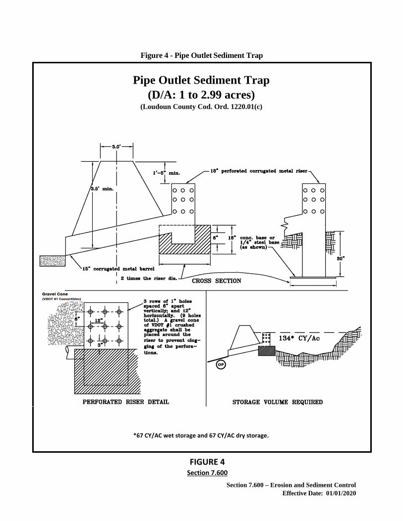
Section 7.600 – Erosion and Sediment Control
Effective Date: 01/01/2020
Figure 4 - Pipe Outlet Sediment Trap
FIGURE 4 Section 7.600
Pipe Outlet Sediment Trap
(D/A: 1 to 2.99 acres) (Loudoun County Cod. Ord. 1220.01(c)
*67 CY/AC wet storage and 67 CY/AC dry storage.

Section 7.600 – Erosion and Sediment Control
Effective Date: 01/01/2020
Recommended Curb Inlet Protection
Side
Elevation
Perspective
View
Design Details
Use two 2” x 6” or one 4” x 4” on each side as spacers cut to the height of the curb (These will be used on both sides of the inlet to act as spacers for the 2” x 4” cross board to create a 3” spillway along the top of the inlet.
Inlet lengths will vary in size. Ensure the 2” x 4” cross board will extend 12” past the inlet on both sides.
Inlets with longer lengths may require additional “spacers” along the cross board for support.
Nail two 2” x 6”spacers together (or optional 4” x 4”)
Nail 2” x 4” cross board flush along the top of the spacers to allow a 2” opening along the bottom to allow storm water to access the inlet after being filtered.
Attach wire mesh along the top of the 2” x 4” cross board to conform with the curb and gutter.
Apply filter stone the entire length of the cross board.
Attach the mesh to the top of the cross board to secure the filter stone.
Attach 2” x 4” anchors on top of each end of the cross board to anchor the inlet protection.
Use sand bags on top of the 2” x 4” anchors to secure the inlet protection to the structure or drive stakes into the ground at the rear of the structure to attach the 2” x 4” anchors to.
Figure 5 - Recommended Curb Inlet Protection
FIGURE 5 Section 7.600

Section 7.700 – Utility Placement
Effective Date: 01/01/2020
7.700 UTILITY PLACEMENT
Installation of new utilities, such as electric, telephone and cable television, shall be
installed underground within new subdivision and site plan developments and to the extent
possible in re-development projects. Such utilities shall be placed under the sidewalks or
within the right-of-way when feasible.

Section 7.800 - Archaeology
Effective Date: 01/01/2020
7.800 ARCHAEOLOGY
7.810 ARCHAEOLOGICAL SURVEY
The purpose of an archaeological survey is to identify the locations of existing
archaeological and historic resources, including cemeteries, burial grounds, and graves on
a property subject to the application.
A. All archaeological surveys required by this Section shall be conducted by a
qualified professional meeting the Qualification Standards as set forth in “the
Secretary of the Interior’s Standards and Guidelines for Archaeology and Historic
Preservation” as defined in 36 CFR 61, Appendix A.
B. Archaeological survey and reporting shall meet the standards set forth in the
Virginia Department of Historic Resources (VDHR) “Guidelines for Conducting
Historic Resources Survey in Virginia.”
C. A Phase I archaeological survey is required for areas of proposed subsurface
disturbance, including, but not limited to, the house/outbuilding footprints,
drainfields, roads and paved areas, sidewalks, utility lines, borrow pits, staging
areas, and stockpiling areas, but is recommended for the entire property. If areas
of proposed subsurface disturbance are changed to include areas not previously
tested, additional Phase I Archaeological testing of the non-tested areas will be
required. A reconnaissance level (“walkover”) survey of any area of the property
not subject to the Phase I Archaeological Survey shall be conducted to identify
potential cemeteries, burial grounds, and/or graves. The results of the
reconnaissance level survey shall be provided with the Phase I archaeological
report.
D. If the Phase I Archaeological Survey is limited only to areas of proposed subsurface
disturbance or if multiple Phase I Archaeological Surveys are submitted for an
application, a separate sheet for informational purposes only and not for recordation
shall be submitted at a maximum 1:2400 scale (1 inch = 200 feet) delineating
existing parcel boundaries, proposed development layout, and boundaries of the
Phase I Archaeological Survey testing areas.
E. The Director may approve a Phase I Archaeological Management Summary
Report, in lieu of the reporting required by VDHR’s “Guidelines for Conducting
Historic Resources Survey in Virginia,” if the Phase I archaeological survey does
not result in the identification of archaeological sites, or results in the identification
of archaeological resources that are determined by the consultant to warrant no
further archaeological investigation. The Phase I Archaeological Management
Summary Report must include the following:
1. A brief description of the property with a vicinity map.

Section 7.800 - Archaeology
Effective Date: 01/01/2020
2. The testing methodology and rationale, including a summary of previously
identified sites in the vicinity and results of historic map research.
3. A topographic map of project area showing areas tested, with the shovel test
locations delineated.
4. The results of fieldwork including artifact inventory and brief description
of any identified sites.
5. The rationale for site recommendations if applicable.
6. Results of the reconnaissance level survey.
F. The Director may waive or modify the requirement for Phase I archaeological
survey and reporting after determining that a site has little or no potential for
cultural resources based on a finding such as (a) the site has been subject to prior
significant grading or ground disturbance beyond normal agricultural use, or (b) the
site contains environmental characteristics (such as slopes, wetlands, hydric soils)
that would have rendered previous human occupation reasonably unlikely.
Variations (WAIV) of the requirement for the reconnaissance level survey shall not
be permitted.
7.820 PRESERVATION OF HISTORIC CEMETERIES, BURIAL GROUNDS, AND
GRAVES
A. In order to preserve existing cemeteries, burial grounds, and graves for human
remains, all preliminary plats of subdivision, and all site plans and construction
plans and profiles if not previously provided with a preliminary plat of subdivision,
shall include a professionally prepared archaeological delineation of the perimeter
boundary of all burials if any cemeteries, burial grounds, or graves are identified
during the archaeological survey. The delineation shall be conducted in accordance
with standard archaeological practices, such as, but not limited to, shallow
mechanical trenching extending outward from location of the visible areas of the
identified cemetery, burial ground, or grave to remove topsoil so that soil
discolorations indicative of burials may be viewed, or systematic probing with rods
to detect differences in soil compaction indicative of burials. The perimeter
boundary of the cemetery, burial ground, or grave shall be delineated five (5) feet
from the edge of the identified burials, and any future burial locations if applicable.
B. The cemetery, burial ground, or grave and associated buffer area as required by the
Zoning Ordinance shall be located within an easement granted to Loudoun County
in a form approved by the County. The perimeter boundary of a cemetery, burial
ground, or grave as determined by the archaeological delineation and the associated
easement shall be indicated on the site plan, construction plans or profiles,
preliminary plat of subdivision, and associated plat applications as required by
Chapter 8. A digital file of the boundary of the cemetery, burial ground, or grave

Section 7.800 - Archaeology
Effective Date: 01/01/2020
prepared in accordance with the Office of Mapping and Geographic Information
Digital Data Submission Guidelines for Cemeteries shall be submitted prior to
approval of the site plan, construction plans or profiles, or preliminary plat of
subdivision.
C. Unimproved pedestrian access to the cemetery, burial ground, or grave shall be
provided on the site plan, construction plans or profiles, preliminary plat of
subdivision, and associated plat applications as required by Chapter 8, either by a
minimum of 15 feet of frontage on a street or by an access easement that shall be a
minimum of 15 feet wide from a street or other point of public ingress.
D. Prior to any land disturbance, protective barriers, such as Super Silt Fence as shown
in Figure 3, or welded wire fence as shown in Figure 6, shall be installed along the
limits of clearing and grading proximate to the cemetery, burial ground, or grave.
E. Subsections A. through D., above, shall not preclude exhumation and re-interment
of burials in accordance with the Code of Virginia. The plan approved by the
Virginia Department of Historic Resources for such exhumation and re-interment
shall be provided to the County Archaeologist prior to exhumation.
7.830 CEMETERY, BURIAL GROUND, AND GRAVE TREATMENT PLAN
A Treatment Plan shall include the following:
A. A map depicting the perimeter boundary of the cemetery, burial ground, or grave;
all associated burial site elements (such as fences, walls, gates, landscape features,
plantings associated with burials, fieldstones, and tombstones); the required and
proposed Cemetery, Burial Ground, and Grave Buffers; existing vegetation to be
preserved or conserved and proposed landscaping, opaque barriers, or hardscaping;
proposed grading; proposed pedestrian access easement; and existing and proposed
surrounding uses.
B. An inventory of existing burial site elements depicted on the map and their
condition.
C. A description of the existing vegetation to be preserved or conserved, or removed,
treatment of invasive species excluding any species planted in association with
burials, and any proposed landscaping within the buffer.
D. A description of the physical demarcation of the perimeter boundary.
E. A description of any proposed opaque barriers, fencing, or hardscaping.
F. A description of any proposed interpretive signage documenting the cultural and
historical significance of the cemetery, burial grounds, or graves.

Section 7.800 - Archaeology
Effective Date: 01/01/2020
G. A description of how the modified buffer will achieve the purpose and intent of the
required Cemetery, Burial Ground, and Grave Buffers, and address how the
cemetery, burial ground, or grave and its historic context is being preserved through
alternative mitigation techniques.

Section 7.900 – References for Chapter 7
Effective Date: 01/01/2020
7.900 REFERENCES FOR CHAPTER 7
American National Standards Institute (arboricultural operations standards).
Codified Ordinances of Loudoun County of Virginia.
"Guide Policy for Roadway Lighting Facilities and Security Lighting Facilities", (VDOT).
Virginia Erosion and Sediment Control Handbook, Division of Soil and Water
Conservation

CHAPTER 8.000
ADMINISTRATIVE PROCEDURES
8.000 OPTIONAL PRE-SUBMISSION MEETINGS PRIOR TO PRELIMINARY
SUBDIVISION, SITE PLAN, PLAT AND CONSTRUCTION PLAN AND
PROFILE APPLICATIONS (PSUB)
8.100 DETAILS OF PLAT AND PLAN REQUIREMENTS
8.100.1 DIGITAL DATA
8.101 GENERAL STANDARDS
8.102 PRELIMINARY PLAT OF SUBDIVISION (SBPL)
8.103 PLATS FOR SUBDIVISION AND OTHER MISCELLANEOUS PLATS
8.103.1 RECORD PLATS (SBRD) 8.103.2 BOUNDARY LINE ADJUSTMENT (BLAD) 8.103.3 PRELIMINARY/RECORD SUBDIVISION (SBPR) 8.103.4 FAMILY SUBDIVISION (SBFM) 8.103.5 SUBDIVISION WAIVER (SBWV) 8.103.6 EASEMENT PLATS – CREATION AND VACATION 8.103.7 DEDICATION/VACATION PLATS (DEDI) 8.103.8 AR-1 AND AR-2 DIVISION PLATS (SBBD)
8.104 FLOODPLAIN STUDY (FPST)
8.105 FLOODPLAIN ALTERATION (FPAL)
8.106 CONSTRUCTION PLANS AND PROFILES (CPAP)
8.107 SITE PLANS (STPL) AND RURAL ECONOMY SITE PLANS (REST)
8.108 RECORD DRAWINGS
8.109 PLAT AND PLAN REVISIONS
8.110 SITE PLAN AMENDMENTS (SPAM)
8.111 GRADING PERMIT APPLICATION
8.112 INDIVIDUAL LOT GRADING PLAN
8.113 LOCATION PLAT
8.114 PLOT PLANS FOR RESIDENTIAL ZONING PERMIT APPLICATIONS

8.200 REQUIREMENTS FOR START OF ANY CONSTRUCTION
8.300 PERFORMANCE AGREEMENT AND BONDING
8.301 PERFORMANCE AGREEMENT SUBMISSION REQUIREMENTS
8.302 TERM OF PERFORMANCE AGREEMENT
8.303 ACCEPTABLE FORMS OF PERFORMANCE BONDS
8.304 BOND ESTIMATE AND BOND AMOUNT
8.305 BOND PROCEDURES AND REQUIREMENTS
8.306 DEBARMENT OF SURETY
8.400 CERTIFICATE OF OCCUPANCY OR USE
8.500 INSPECTIONS

Section 8.000 – Administrative Procedures
Effective Date: 01/01/2020
CHAPTER 8.000
ADMINISTRATIVE PROCEDURES
This chapter establishes certain criteria which must be met to allow a systematic approach to a
comprehensive review process. In addition to the information below, it is the developer's
responsibility to provide all necessary information to allow reviewing agencies to adequately
determine if all requirements of pertinent ordinances and provisions of this manual have been met.
8.000 OPTIONAL PRE-SUBMISSION MEETINGS PRIOR TO PRELIMINARY
SUBDIVISION, SITE PLAN, PLAT AND CONSTRUCTION PLAN AND PROFILE
APPLICATIONS (PSUB)
In order to familiarize an applicant or landowner with the development review process; or
to provide an applicant or landowner the opportunity to discuss development alternatives;
or to provide an applicant or landowner the opportunity to discuss a particular property and
any environmental and cultural resource issues; an applicant or landowner may request a
pre-submission meeting prior to submission of Preliminary Subdivision, Site Plan, Plat, or
Construction Plan and Profile applications. To facilitate discussion at the pre-submission
meeting, a sketch plan, narrative of the proposed land use proposal, and existing site
conditions in Loudoun County Geographic Information System (LOGIS) shall be
submitted to the County.
Upon receipt of the above information, the County shall schedule a Pre-submission meeting
to be held within ten (10) working days. During the Pre-submission meeting, the County
and applicant shall collaborate and share design options to meet the proposed land use
objectives while preserving and protecting the environmental and cultural resources
identified on the subject site. Conclusions and agreements made at the Pre-submission
meeting shall be documented for future reference by the applicant and the County during
the land development application preparation, review and approval process. For Rural
Economy Site Plans, such documentation shall include any approved modifications to
Section 8.107.

Section 8.100 – Details of Plat and Plan Requirements
Effective Date: 01/01/2020
8.100 DETAILS OF PLAT AND PLAN REQUIREMENTS
The information contained in the following subsections is required to be included on plats
and plans reviewed by the Department of Building and Development.
8.100.1 DIGITAL DATA
If produced electronically, and if not previously provided, an electronic copy of required
submission materials (i.e. plats, plans, exhibits, studies, reports, legal documents, and
letters) shall be included with each plat and plan submission in PDF format or such other
standard digital format as specified by the Director. The County will provide a release of
liability, if requested.
8.101 GENERAL STANDARDS
The information in this section gives an explanation of standard plat and plan requirements.
See the specific requirements of each plat or plan for the requirements of each document.
A. Standards:
1. Scale: The scale of the plat or plan shall be shown in feet.
2. Proposed Name of Subdivision or Development: No proposed names of
subdivisions or developments shall duplicate or closely resemble the name
of any existing or currently proposed subdivision or development in
Loudoun County. Name should include Phase or Section Number, as
applicable.
3. Revision Block: A revision block shall be shown on the Cover Sheet (or
first sheet) of the plat set and all sheets of the plan set. The Cover Sheet
revision block shall contain a summary of all revisions made to any sheet
of the plat, or plan, in substantially the following form:
Rev. No. Sheet Number and Revision Description Date
All other sheets of the plan set shall include a revision block itemizing the revisions
applicable to each sheet, in substantially the following form:

Section 8.100 – Details of Plat and Plan Requirements
Effective Date: 01/01/2020
Rev. No. Revision Description Date
4. Source of Title: The source of title of the owner (the deed book and page
number or instrument number of the last instrument in the chain of title for
all included property).
5. Zoning Requirements:
a. Preliminary Plats, Site Plans, Construction Plans and Profiles: In
tabular form show the specific zoning requirements, in accordance
with the Zoning Ordinance including proffered or special exception
conditions, for the subject property and the existing zoning districts,
to include but not limited to: applicable version of the Zoning
Ordinance (i.e. 1972, 1993, Revised 1993); Zoning district; overlay
zoning districts; minimum lot area; minimum lot width; maximum
length/width ratio; minimum front, side and rear yards; maximum
floor area ratio; maximum lot coverage; maximum building heights;
parking spaces required and provided (including standard and
handicap accessible); open space requirements; proposed uses and
proposed number of lots. For construction plans and profiles and
site plans show floor area ratio or lot coverage calculations as
required by the Zoning Ordinance. A note may be added to the plat
stating that the zoning requirements are for depiction of current
ordinance requirements only and may be subject to change.
b. Plats: In tabular form show the specific zoning requirements, in
accordance with the Zoning Ordinance including proffered or
special exception conditions, for the subject property and the
existing zoning districts, to include but not limited to: applicable
version of the Zoning Ordinance (i.e. 1972, 1993, Revised 1993);
Zoning district; overlay zoning districts; minimum lot area;
minimum lot width; maximum length/width ratio; minimum front,
side and rear yards; maximum lot coverage; maximum building
heights; open space requirements; proposed number of lots. A note
may be added to the plat stating that the zoning requirements are for
depiction of current ordinance requirements only and may be subject
to change.
6. Associated Land Development Application Information: Reference to land
development application numbers and corresponding approval dates for

Section 8.100 – Details of Plat and Plan Requirements
Effective Date: 01/01/2020
land development applications preceding the subject application submission
that involve the subject property. Land development applications involving
only adjacent sections, or expired or superseded land development
applications, do not need to be listed.
7. Vicinity Map: The plat or plan shall show the location of the proposed
subdivision by an insert vicinity map, drawn to a scale 1 inch equals not
more than 2000 feet or other appropriate scale as permitted by the Director.
a. The existing perimeter boundary line of the proposed subdivision
and/or site plan and of any larger tract of which the subdivision
and/or site plan forms a part.
b. Adjoining roads or principal access points with their names and
route numbers.
c. Town boundary lines within one mile of the proposed subdivision.
d. North arrow.
8. Coordinate Grid Tics: Coordinate grid tics and values reflecting the North
American Datum of 1983 (NAD 83 HARN) State Plane Virginia North (in
US Survey Foot) coordinate grid system with at least three tics or
intersection points shall be shown on each plan sheet, for informational
purposes, in intervals of no less than 250 foot increments and no more than
1,000 foot increments. For record plats, grid system coordinates of at least
two adjacent corners shall be included, if any point in the subdivision is
within 1/2 mile of an NGS or equivalent triangulation or traverse station
established within the standards for a second order geodetic monument.
(Projects that were started prior to November 9, 2009, may use the
previously required NAD 27 datum.)
9. Adjoining Property Information: MCPI (PIN), adjacent zoning district, and
departing property lines shall be shown. For preliminary plats, construction
plans and profiles, and site plans the existing adjacent land use shall be
indicated for the purpose of determining buffer requirements per the Zoning
Ordinance.
10. Zoning District and Jurisdictional Boundaries: The zoning district
boundaries shall be shown when a property is located in more than one
zoning district. Zoning overlay district boundaries shall be shown when a
property is located within any zoning overlay district. Jurisdictional
boundaries shall be shown for property located in Loudoun County and a
town or another county, or which falls under the subdivision control of a
town.

Section 8.100 – Details of Plat and Plan Requirements
Effective Date: 01/01/2020
11. Yard and Setback Lines: Front, side and rear yard and setback lines
required by the Zoning Ordinance and/or proffers shall be shown as dashed
lines or in tabular form. The dimension from each lot line and the length of
the front yard line shall be clearly illustrated and identified. A note may be
added to the plat stating that the yard and setback lines are for depiction of
current ordinance requirements only and may be subject to change.
12. Stakeout Note:
A note shall be provided stating that if requested by the Director, the
approximate location of proposed entrances from State-maintained roads
will be staked, and the name, address and telephone number of the party
who will respond to the Director's request for field assistance, when
required, to identify specific areas of proposed development as related to
existing site conditions.
13. Approval Block: An approval block shall be provided per the following
with appropriate application number provided within:
APPROVAL BLOCK
LAND DEVELOPMENT APPLICATION
NUMBER__________________________
_______________________________ _____________
Director of Building & Development Date
14. Fee Check: A fee check, payable to the County of Loudoun, shall be
attached to the plat or plan submission. Fee schedules are available from
the Director.
15. Land Development Application Form: A complete and executed Land
Development Application Form with original signatures, as provided by the
Director.
16. MCPI (PIN) Reference: The MCPI number is required for all properties
that are a part of the application. Such references may be made in tabular
form or shown on the plat or plan.
17. Topography: Topographic information, indicating when and by what
means it was made, having contour intervals of 2 feet or less, showing all
the area covered by the site, including a 50 foot overlap, and related to the
North American Vertical Datum of 1988 (NAVD 88). Areas of forest or
other vegetated cover shall also be shown. Champion trees as identified in

Section 8.100 – Details of Plat and Plan Requirements
Effective Date: 01/01/2020
adopted Federal and State documents shall also be identified. (Projects that
were started prior to November 9, 2009, may use the previously required
NGVD 29 datum.)
18. Seal and Signature: The seal, signature, and date of the Licensed
Professional Engineer (P.E.) or Surveyor who prepared this plat or plan
shall be shown on each sheet.
19. Surveyor’s Certificate: A certificate, endorsed by the Licensed Professional
Engineer (P.E.) or Surveyor, setting forth the source of title of the owner of
the property (deed book and page number or instrument number where
owner acquired the property) and the place of record of the last instrument
in the chain of title (deed book and page number or instrument number of
the last instrument that vacated, relocated, or otherwise altered any
boundary lines of the property, or subdivided the property), in accordance
with Section 15.2-2262 of the Code of Virginia, as amended.
20. Source of Floodplain Note: A note shall be provided that describes the
source of the existing floodplain information as follows:
"There is no floodplain on the property that is the subject of this application.
The current Flood Insurance Rate Map (FIRM) of Loudoun County
Community Panel Number for the property that is the subject of this
application is {insert number}, effective {insert date}.”
OR
“There is floodplain on the property that is the subject of this application.
The current Flood Insurance Rate Map (FIRM) of Loudoun County
Community Panel Number for the property that is the subject of this
application is {insert number}, effective {insert date}.” The depicted
boundary of the existing floodplain is based on {select one} [if applicable,
a site-specific floodplain study or floodplain alteration {provide application
number and approval date}] [the FIRM] [{other source with description}]."
21. Archaeology Notes: A note shall be provided to describe each archaeology
survey conducted for the property as follows. No note needs to be provided
if a particular survey was not performed.
“A Phase I Archaeological Survey was completed for the property, {insert
report title}, by {insert company name} in {insert month and year}.”
“A Phase II Evaluation, {insert report title}, was completed for Site {insert
number(s)} by {insert company name} in {insert month and year}.”
“A Phase III Data Recovery, {insert report title}, was completed for Site
{insert number(s)} by {insert company name} in {insert month and year}.”

Section 8.100 – Details of Plat and Plan Requirements
Effective Date: 01/01/2020
“A Cemetery Delineation, {insert report title}, was completed to identify
the boundary of the cemetery associated with Site {insert number(s)} by
{insert company name} in {insert month and year}.”
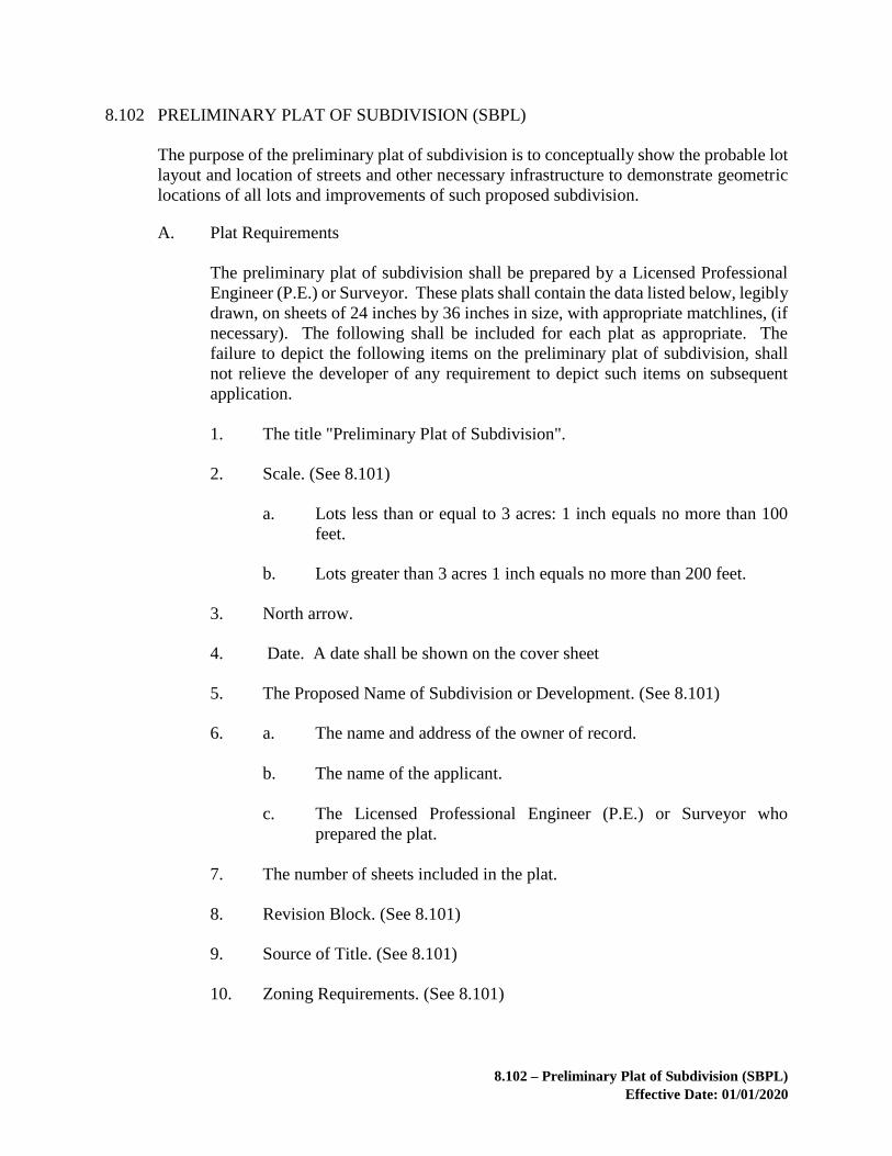
8.102 – Preliminary Plat of Subdivision (SBPL)
Effective Date: 01/01/2020
8.102 PRELIMINARY PLAT OF SUBDIVISION (SBPL)
The purpose of the preliminary plat of subdivision is to conceptually show the probable lot
layout and location of streets and other necessary infrastructure to demonstrate geometric
locations of all lots and improvements of such proposed subdivision.
A. Plat Requirements
The preliminary plat of subdivision shall be prepared by a Licensed Professional
Engineer (P.E.) or Surveyor. These plats shall contain the data listed below, legibly
drawn, on sheets of 24 inches by 36 inches in size, with appropriate matchlines, (if
necessary). The following shall be included for each plat as appropriate. The
failure to depict the following items on the preliminary plat of subdivision, shall
not relieve the developer of any requirement to depict such items on subsequent
application.
1. The title "Preliminary Plat of Subdivision".
2. Scale. (See 8.101)
a. Lots less than or equal to 3 acres: 1 inch equals no more than 100
feet.
b. Lots greater than 3 acres 1 inch equals no more than 200 feet.
3. North arrow.
4. Date. A date shall be shown on the cover sheet
5. The Proposed Name of Subdivision or Development. (See 8.101)
6. a. The name and address of the owner of record.
b. The name of the applicant.
c. The Licensed Professional Engineer (P.E.) or Surveyor who
prepared the plat.
7. The number of sheets included in the plat.
8. Revision Block. (See 8.101)
9. Source of Title. (See 8.101)
10. Zoning Requirements. (See 8.101)
8.102 – Preliminary Plat of Subdivision (SBPL)
Effective Date: 01/01/2020
In addition to the applicable zoning requirements, as stated in Section
8.101.A.5.a, the following note shall be provided on preliminary plats of
subdivision which are preceded by a rezoning or special exception
application:
"All development within this subdivision shall be in substantial
conformance with (A) the requirements of the applicable concept
development plan, proffers and special exception conditions in
accordance with (insert specific reference to County application
numbers), pursuant to which such concept development plan,
proffers and special exception conditions were approved, and (B)
any conditions set forth as conditions of approval of this preliminary
plat."
11. Associated Land Development Application Information. (See 8.101)
12. Election District and Loudoun County, Virginia in Title Block.
13. Vicinity Map. (See 8.101)
14. Boundary lines and total acreage of the proposed subdivision and the
acreage remaining in the original tract, if any.
15. Proposed lot lines, (showing approximate dimensions), proposed block and
lot numbers, and the approximate area of each lot.
16. Coordinate Grid Tics. (See 8.101)
17. Adjoining Property Information. (See 8.101)
18. The Zoning District and Jurisdictional Boundaries. (See 8.101)
19. MCPI (PIN) Reference. (See 8.101)
20. The approximate location of existing buildings within the subdivision.
21. The proposed location, width, centerline and projected Average Daily
Traffic (ADT's) of each road or other public or private way within the
subdivision. Pedestrian circulation paths shall be shown, including
proposed trails and sidewalks, if such improvement is required.
22. The approximate location, width, ADT's and centerline of adjoining roads,
and access easements with their names and/or route numbers.
23. Proposed roads shall include approved and/or reserved road names per the
Codified Ordinances of Loudoun County.

8.102 – Preliminary Plat of Subdivision (SBPL)
Effective Date: 01/01/2020
24. Proposed Yard and Setback Lines. (See 8.101)
25. The approximate location and approximate area of any land to be dedicated
or reserved for public use, road right-of-way use, or common use of future
property owners in the subdivision. The location of any existing and
proposed conservation easements.
26. Approximate watercourse locations and names, if any, and the boundaries
of the FOD, or the proposed boundaries of the floodplain as shown on a
floodplain study or floodplain alteration which has been submitted and
accepted by the County for review in accordance with Chapter 5 of this
manual.
27. Source of Floodplain Note. (See 8.101)
28. General location of existing drainage ways, ponds, springs, onsite sewage
disposal, onsite water supply systems and existing and proposed public
water and sewer lines.
29. Archaeology Notes. (See 8.101)
30. The locations of archaeological sites, historic structures, human cemeteries,
burial grounds, graves, historic districts, and historic landmarks on the site,
if identified by the Archaeological Surveys performed for the property in
accordance with Chapter 7 of this manual and the Phase II Evaluation and
Phase III Data Recovery, if applicable.
31. Current topographic information, indicating when and by what means it was
made, having contour intervals of 5 feet or less, showing all the area covered
by the subdivision not including residue parcel(s) and related to the North
American Vertical Datum of 1988 (NAVD 88). Loudoun County
Geographic Information System (LOGIS), which depicts 4-foot contour
intervals, may be used. Areas of forest or other vegetated cover shall also
be shown. In cases where a Tree Survey has been performed for the
property, identified cover type areas and specimen trees shall be depicted.
Champion trees as identified in adopted Federal and State documents shall
also be identified. (Projects that were started prior to November 9, 2009,
may use the previously required NGVD 29 datum.)
32. Stakeout Note. (See 8.101)
33. Graphically shown on the plat, Ldn 65 and Ldn 60 aircraft noise contours
and any area within one mile of the Ldn 60 aircraft noise contour, as defined
by the Zoning Ordinance.
34. Approval Block. (See 8.101)

8.102 – Preliminary Plat of Subdivision (SBPL)
Effective Date: 01/01/2020
35. Proffered preservation areas shall be clearly delineated (e.g., trees,
structures, etc.).
36. For lots less than 20,000 square feet in size a typical lot detail shall be
provided at a scale of not less than 1 inch = 50 feet.
37. A tabulation of lot yield for those properties being developed pursuant to
the Cluster Subdivision Option or Principal/Subordinate Option in the AR-
1 or AR-2 Zoning Districts.
38. Wetlands data as follows:
a. Potential jurisdictional waters and wetlands as identified by the
Loudoun County Predictive Wetlands Model or a consultant
wetland delineation performed in accordance with Army Corps of
Engineers (Corps) standards shall be depicted on the plat.
b. A note referencing the source of the wetland information depicted
on the plat (including the Corps Jurisdictional Determination
number and date, if it exists) and indicating that all applicable state
and federal permits shall be obtained prior to disturbances within
jurisdictional waters and wetlands shall be provided on the plat.
39. Very Steep Slope Areas and Moderately Steep Slope Areas, as defined and
regulated in the Zoning Ordinance and as identified in Loudoun County
Geographic Information System (LOGIS), or based on a topographic
analysis where a contour interval of 5 feet or less is used.
40. The boundaries of Scenic Creek Valley Buffer and other applicable County
environmental buffers.
41. A soils map certification in accordance with Chapter 6 of this manual.
42. Overlay Districts as established in the Zoning Ordinance.
B. Items to Accompany Preliminary Plats of Subdivision
The following items shall accompany the submission of a preliminary plat of
subdivision:
1. For any subdivision to be served in accordance with the requirements of the
LSDO section relating to onsite sewage disposal systems, written approval
of the proposed locations of sewage disposal systems shall be obtained from
the Health Director or his designee and submitted with the preliminary plat.
For any subdivision proposed to be served by on site wells, the developer
shall submit with the preliminary plat written verification from the Health

8.102 – Preliminary Plat of Subdivision (SBPL)
Effective Date: 01/01/2020
Director, or his designee, that the Hydrogeologic Report has been reviewed
and approved in accordance with Chapter 6 of this manual.
2. Fee Check. (See 8.101)
3. Land Development Application Form. (See 8.101)
4. If not previously provided, an archaeological survey report prepared in
accordance with Chapter 7 of this manual. If human cemeteries, burial
grounds, or graves are identified, an archaeological delineation prepared in
accordance with Chapter 7.
5. If within the Limestone Overlay District or Mountainside Development
Overlay District, documentation of the submission of an application for, or
the submission of a private, Preliminary Soils Review in accordance with
Chapter 6 of this manual.
6. A letter from the Virginia Department of Conservation and Recreation,
Division of Natural Heritage identifying occurrences of natural heritage
resources on the property such as the habitat of rare, threatened, or
endangered plant and animal species, unique or exemplary natural
communities, and significant geologic formations. If an endangered and
threatened species survey has been completed for the property, a copy of
the report shall also be submitted.
7. If applicable, plan and analysis of VDOT connectivity requirements and
locations of stub out streets.
C. The following items shall be required prior to approval of Preliminary Plats of
Subdivision:
1. If not previously provided, a digital file of the boundary of any cemetery,
burial ground, or grave prepared in accordance with the Office of Mapping
Digital Data Submission Guidelines for Cemeteries.
D. Preliminary Plat Review
Following the first review by the County, the Preliminary Plat may be conditionally
approved. After the first review, the Director shall prepare and provide an Official
Comment Letter setting forth the corrections and revisions that are required or
recommended, including, by attachments, the referral comments from the referral
agencies. When the Official Comment Letter is received by the applicant, applicant
may submit a written response to the Director that it will comply with all County
and referral comments as part of its Construction Plans and Profiles and record plat
submissions. The Director will consider this response, and if the Director finds that
the revision of the Preliminary Plat in accordance with the Official Comment Letter

8.102 – Preliminary Plat of Subdivision (SBPL)
Effective Date: 01/01/2020
will not substantially alter the conceptual layout of the Preliminary Plat, such
Preliminary Plat shall be conditionally approved.

Section 8.103 – Plats for Subdivision and Other Miscellaneous Plats
Effective Date: 01/01/2020
8.103 PLATS FOR SUBDIVISION AND OTHER MISCELLANEOUS PLATS
A. Plat Requirements
The plats shall be prepared by a Licensed Professional Engineer (P.E.) or Surveyor.
These plats shall contain the data listed below, legibly drawn, on sheets of 18 inches
by 24 inches in size, with appropriate matchlines (if necessary). The following
shall be included for each plat as appropriate.
1. Scale. (See 8.101)
a. Lots less than 1/4 acre; 1 inch equals no more than 50 feet.
b. Lots 1/4 to 3 acres; 1 inch equals no more than 100 feet.
c. Lots greater than 3 acres; 1 inch equals no more than 200 feet.
2. North arrow.
3. Date.
4. The name of the subdivision. (See 8.101)
5. a. The name of the owner(s) of record.
b. The name and address of the Licensed Professional Engineer (P.E.)
or Surveyor who prepared the plat.
6. Number of sheets included in the plat.
7. Revision Block. (See 8.101)
8. MCPI (PIN) Reference. (See 8.101)
9. Seal and Signature. (See 8.101)
10. Surveyor’s Certificate. (See 8.101)
11. The boundary survey with an error of closure within the limits established
by the Commonwealth of Virginia.
12. Coordinate Grid Tics. (See 8.101)
13. The plat(s), as submitted for signature and recordation, shall be drawn
legibly and accurately per Virginia State Library and Archives Standards
for plats.

Section 8.103 – Plats for Subdivision and Other Miscellaneous Plats
Effective Date: 01/01/2020
14. Zoning Requirements. (See 8.101)
15. Zoning District and Jurisdictional Boundaries. (See 8.101)
16. Associated Land Development Application Information. (See 8.101)
17. Election District and Loudoun County, Virginia in the Title Block.
18. Vicinity Map. (See 8.101)
19. The plat shall show parcel and lot lines, showing dimensions, block and lot
numbers, and the area of each parcel or lot including area outside of major
floodplain. Dimensions shall be shown in feet and decimals of a foot to the
closest one-hundredth of a foot, and bearings in degrees, minutes, and
seconds. The data for curves shall be shown in detail at the curve or in a
curve data table containing the following: radius, delta, arc, tangent, chord,
and chord bearing. Acreage shall be shown to the ten thousandth decimal
place and square footage to the nearest whole foot and all of the remaining
area in the original tract/residue parcels to the nearest one hundredth of an
acre.
20. Roadways shall include approved and/or reserved names per the Codified
Ordinances of Loudoun County. Existing public roadways shall include
route numbers and road names.
21. The location, dimensions of easements, dimensions and area of roadways,
public sites (schools, fire and rescue facilities, etc.), parks and other public
areas shall be included.
22. Adjoining Property Information. (See 8.101)
23. Graphically shown on the plat, Ldn 65 and Ldn 60 aircraft noise contours
and any area within one mile of the Ldn 60 aircraft noise contour, as defined
by the Zoning Ordinance.
24. Yard and Setback Lines. (See 8.101)
25. If land is being dedicated or reserved for public use for roads, parking areas
for public use, or for common use of the future property owners of the
subdivision, the record plat shall so state and illustrate such.
26. As applicable, the location, width, and centerline of existing/proposed
roads, easements, and public or private rights-of-way within or immediately
abutting the property. Instrument numbers or deed book and page numbers
shall be provided, as applicable.

Section 8.103 – Plats for Subdivision and Other Miscellaneous Plats
Effective Date: 01/01/2020
27. If not otherwise contained within the deed accompanying the plat, the plat
shall contain a statement to the effect that the subdivision is with the free
consent and in accordance with the desire of the undersigned owners and
trustees of the property and shall be duly acknowledged in accordance with
Section 15.2-2264 of the Code of Virginia of 1950, as amended.
28. The plat shall indicate Health Director approved sewerage disposal systems
and water supply systems, as specified in the Loudoun County Codified
Ordinances.
29. The plat shall contain a statement setting forth the persons or entities
responsible for maintenance of stormwater detention, drainage facilities,
easements, sidewalks, trails, lighting and other facilities, as applicable.
30. In the AR-1, AR-2, A-10 and A-3 Zoning Districts, record plats shall
contain the following statement:
"In all areas within the AR-1, AR-2, A-10 or A-3 Zoning Districts,
agricultural and rural economy activities are the preferred land uses.
Owners of land within AR-1, AR-2, A-10 or A-3 Zoning Districts are
hereby notified that agricultural and rural economy activities shall be given
preference by the County when conflicts arise concerning the compatibility
of such farm or rural economy uses with adjacent or nearby non-farm or
non-rural economy uses. The County shall not restrict or interfere with
farming and rural economy activities in AR-1, AR-2, A-10 or A-3 Zoning
Districts. The farming and rural economy activities, including such effects
as noise, odors, and machinery traffic, shall not be recognized or accepted
by the County as valid or proper cause for complaints from adjacent or
nearby residential neighbors."
31. Watercourses and names, if any.
32. Source of Floodplain Note. (See 8.101)
33. A floodplain easement in accordance with Chapter 5 of this manual.
34. Archaeology Notes. (See 8.101)
35. The boundaries of any archaeological delineation of human cemeteries,
burial grounds, or graves, and the associated easement and pedestrian access
easement.
36. Restrictive covenants. Instrument or deed book and page numbers shall be
provided, as applicable.
37. An Approval Block. (See 8.101)

Section 8.103 – Plats for Subdivision and Other Miscellaneous Plats
Effective Date: 01/01/2020
38. If private roads or access easements are proposed, the following notes shall
be provided:
a. “Construction of the private road(s) and/or access easement(s)
shown hereon shall conform to the standards set forth in the
Loudoun County Land Subdivision and Development Ordinance
and Chapter 4 of the Facilities Standards Manual.”
AND
b. One of the following notes, as applicable:
i. “The streets in this subdivision do not meet the standards
necessary for inclusion in the system of state highways and
will not be maintained by the Virginia Department of
Transportation or the County and are not eligible for rural
addition funds or any other funds appropriated by the
General Assembly and allocated by the Commonwealth
Transportation Board.”
OR
Where streets are required to meet VDOT standards for
design and construction, but which are not intended for
acceptance as part of the secondary system of state
highways.
ii. “Although the streets in this subdivision are required to meet
VDOT standards for design and construction, such streets
are not intended for inclusion in the system of state highways
and will not be maintained by the Department of
Transportation or the County and are not eligible for rural
addition funds or any other funds appropriated by the
General Assembly and allocated by the Commonwealth
Transportation Board.”
AND
c. “The access serving these lots is private and its maintenance,
including snow removal, is NOT a public responsibility.”
39. The location of structures (e.g., buildings, barns, sheds) to be retained,
including stone walls within areas to be dedicated for public right-of-way.
40. Designation of ADU lots in accordance with Zoning Ordinance.

Section 8.103 – Plats for Subdivision and Other Miscellaneous Plats
Effective Date: 01/01/2020
41. If the property is being developed pursuant to the Principal/Subordinate
Subdivision Option, the following as appropriate:
a. Tabulations showing the lot yield originally calculated for the
Originating Tract, all prior subdivisions from the Originating Tract,
and all resulting Principal Lots and number of Subordinate Lots
created pursuant to each such subdivision.
b. Labels clearly identifying the Principal and Subordinate lot (s).
c. A note stating that “Subordinate lots are ineligible for further
subdivision.”
42. If the property is being developed pursuant to the Cluster Subdivision
Option in the AR-1 or AR-2 Zoning District, the following as appropriate:
a. A tabulation of density for such cluster subdivision.
b. Inclusion of note on the record plat and documentation within the
deed stating that all lots are ineligible for further subdivision.
43. All subdivisions which include AR or TR zoned property shall include a
note on the record plat and within the deed indicating that agricultural
operations enjoy the protection of the Right to Farm Act.
B. Items to Accompany Plats
The following items shall accompany the submission of the plat.
1. Verification of Water Supply and Sewage Disposal.
a. If not already provided as part of a Preliminary Subdivision:
i. A letter signed by the Health Director evidencing
conformance with applicable requirements of the County
Health Department.
ii. If public water or public sewerage is to be provided by an
entity other than Loudoun Water, a letter signed by an
authorized official of that entity shall be submitted indicating
that service can and will be provided.
2. Fee Check. (See 8.101)
3. Land Development Application Form. (See 8.101)

Section 8.103 – Plats for Subdivision and Other Miscellaneous Plats
Effective Date: 01/01/2020
4. If not previously provided with a Preliminary Plat of Subdivision or
Construction Plans and Profiles, Steep Slopes data as follows:
a. For any proposed parcel of land or road that includes within its
boundaries Very Steep Slope Areas and/or Moderately Steep Slope
Areas, as defined and regulated in the Zoning Ordinance, the
following shall be depicted on a separate sheet for informational
purposes only and not for recordation: topographic information at
contour intervals of 5 feet or less and the location and extent of Very
Steep Slope Areas and Moderately Steep Slope Areas; land
disturbing activities including, but not limited to, any proposed
building and structure sites, driveways and paved areas, drainfields
and associated septic lines, wells and associated water lines, minor
utilities, and public sanitary sewer and water lines; and mitigation
measures. Such information shall satisfy Locational Clearance
submission requirements for Steep Slope Areas.
C. Final Documents
Prior to plat approval, the following items must be submitted for review and
approval to the Director:
1. If improvements for which a performance bond is required under Section
8.300 of this chapter are not completed, a performance bond in the form of
a cash escrow, letter of credit, or corporate surety bond, along with the
appropriate performance agreement, shall be submitted. Such performance
bond must be accepted by the Board of Supervisors or designee prior to plat
approval.
2. An unexecuted copy of the deed. Such deed shall:
a. Contain a correct description of the land subdivided or adjusted and
state that such subdivision or adjustment is with the free consent and
in accordance with the desire of the undersigned owners and trustees
of the property and shall be duly acknowledged in accordance with
Section 15.2-2264 of the Code of Virginia, as amended.
b. Contain language such that, when the deed is recorded, it shall
operate to transfer, in fee simple, to the Board of Supervisors such
portion of the premises platted as is on the plat set apart for roadways
or other public use, and transfer to the Board of Supervisors, or to
such association or public authority as the Board of Supervisors may
provide, any easement indicated on the plat as the Board of
Supervisors may require.
c. Contain protective or restrictive covenants, if applicable.

Section 8.103 – Plats for Subdivision and Other Miscellaneous Plats
Effective Date: 01/01/2020
d. Contain, when applicable, provisions for maintenance and
indemnification by the property owner with respect to any structure,
including permanent fences and stone walls, within the proposed
and future public right-of-way.
3. When the developer is required to establish an owners' association prior to
approval of the plat to satisfy proffer or other zoning or regulatory
requirements, or in cases where land or facilities are to be conveyed to and
owned in perpetuity by an owner's association, copies of the owner's
association’s documents shall be submitted.
For properties located within the Goose Creek Reservoir Protection area as
defined in Chapter 5 of this manual, such owner’s association documents
shall include covenants requiring the association to maintain the storm
drainage inlet structure markings described in Chapter 5 and covenants
restricting the use of pesticides, herbicides and fertilizers to those materials
which are labeled safe for aquatic use.
4. A letter from the obligor acknowledging that a maintenance and
indemnification agreement satisfactory to the Board of Supervisors to
provide for public facilities maintenance must be executed and delivered to
the Director prior to final release of the financial guarantee.
5. Certificate by subdivider that structures subject to Zoning Ordinance
minimum yard requirements, which are not shown on the plat, will be
removed, unless satisfactory alternate arrangements have been approved by
the Director.
6. Paper copies as requested by the County.
7. If not included in the deed:
a. A Deed of Release if there are deed of trust trustees who are not
parties and signatories to the deed; or
b. A letter or other documentation from the owner which certifies that
there is no deed of trust lien on the property.
8. Water or sewerage facility documentation:
a. For development(s) served by public water or sewerage facilities,
documentation from the Loudoun County Sanitation Authority
(Loudoun Water), or appropriate town, indicating that a
performance bond adequate to assure the installation of water or
sewerage facilities in a manner which will satisfy its requirements
has been approved.

Section 8.103 – Plats for Subdivision and Other Miscellaneous Plats
Effective Date: 01/01/2020
b. For development(s) served by private well or septic facilities,
documentation from the Loudoun County Health Department
indicating that such facilities have been approved.
9. A copy of the document establishing the funding mechanism providing
maintenance of the common facilities in accordance with the Zoning
Ordinance (AR Districts only).
10. A copy of a minimum two year maintenance contract if a communal water
and/or sewage disposal system is to be maintained by an entity other than
the Loudoun County Sanitation Authority (Loudoun Water) (AR Districts
only).
D. Standard Process
The following process is required for plat applications (“Plats”) that are based on
construction plans and profiles or site plans (“Plans”). It does not apply to any
easement, dedication, boundary line adjustment, family subdivision, subdivision
waiver, preliminary/record plat application that does not involve construction
plans, or other plats as approved by the Director. Any application that fails to
provide all the information required in this section will be returned without review
and, upon resubmission, placed after all other applications that have been submitted
prior to such resubmission.
1. The first submission of the Plat shall not be submitted prior to the second
submission of the Plans. The first submission of the Plat shall address, as
appropriate, all of the County’s first review comments on the Plans. The
first submission of the Plat shall be submitted without Legal Documents,
except that the Deed of Subdivision, Dedication and Easements may be
submitted.
2. The second submission of the Plat shall address all of the first submission
Plat referral comments. The second submission of the Plat shall be
accompanied by the submission of the Legal Documents which shall have
been prepared based upon the second submission Plat and in conformance
with any applicable proffers or conditions. For the purpose of this process,
Legal Documents shall include, as applicable, Deed of Subdivision,
Dedication and Easements, Deed of Open Space Easement, ADU
Covenants, and Declaration of Covenants or Supplementary Declaration of
Covenants. Legal Documents shall be forwarded by the project planner to
the Office of the County Attorney for review. Review comments regarding
the Legal Documents shall be provided to the project planner by the Office
of the County Attorney. The review comments associated with the second
submission Plat and first submission Legal Documents will be forwarded to
the applicant upon completion.

Section 8.103 – Plats for Subdivision and Other Miscellaneous Plats
Effective Date: 01/01/2020
3. The third submission of the Plat and second submission of the Legal
Documents shall address all of the second submission Plat and first
submission Legal Documents referral comments. The second and all
subsequent submissions of the Legal Documents shall each be highlighted
by the document preparer to reflect all revisions to the immediately prior
submission. It is also encouraged that, where appropriate, Plats be
highlighted to reflect all revisions to the plat. The third submission Plat and
second submission Legal Documents shall not be submitted until the Plans
upon which the Plat is based have been approved and the bond amount
approved. A copy of the County staff bond estimate approval letter shall be
submitted with the third submission of the plat (second submission of Legal
Documents).
4. Staff will complete review of the third submission Plat and second
submission Legal Documents within 3 weeks and forward comments on
both Plat and documents within 5 working days after receipt of comments
from the Office of the County Attorney.
5. Required associated documents such as Performance Agreements and
Bonds and Cash Contribution Agreements, shall be submitted separately.
These documents should be submitted at least four weeks prior to the
anticipated Plat approval. The review of these documents will follow the
current procedures and timelines. In any event, bonding documents, when
required, must be posted and accepted prior to formal Plat Approval.
6. After review of the third submission Plat and second submission Legal
Documents, both plat and documents should be able to be approved or near
approval. However, if the applicant fails to properly address previous
comments such that a subsequent submission of either the plat or the
documents is necessary, subsequent submissions will be reviewed after all
other applications that have been submitted prior to such subsequent
submission.
7. The primary review agencies may include Loudoun Water and the Loudoun
County Health Department (LCHD). The County does not exercise direct
control over Loudoun Water, which is a separate Authority, or LCHD,
which is a State Agency, and cannot therefore commit Loudoun Water or
LCHD to any time line or comment period. Regardless of whether or not
the County has received Loudoun Water or LCHD comments, County
comments will be forwarded as soon as they are completed. Loudoun Water
and LCHD referral comments will not be required prior to resubmission of
an Application (but will ultimately need to be addressed in order to obtain
final approval).

Sub-Section 8.103.1 – Record Plats (SBRD)
Effective Date: 01/01/2020
8.103.1 RECORD PLATS (SBRD)
In addition to the requirements within Section 8.103, the application for a record plat shall
also include the following:
A. Plat Requirements
1. The title "Record Plat".

Sub-Section 8.103.2 – Boundary Line Adjustment (BLAD)
Effective Date: 01/01/2020
8.103.2 BOUNDARY LINE ADJUSTMENT (BLAD)
In addition to the requirements within Section 8.103, the application for a boundary line
adjustment shall also include the following:
A. Plat Requirements
1. The title "Boundary Line Adjustment".
2. Exterior boundary dimensions shall be shown and may be taken from
existing surveys of record or new surveys. In all cases, new interior
boundary lines shall include the dimensions shown in feet and decimals of
a foot to the closest one-hundredth of a foot, and all bearings in degrees,
minutes, and seconds. The data for curves shall be shown in detail at the
curve or in a curve data table containing the following: radius, delta, arc,
tangent, chord, and chord bearing. Old property lines will be shown as
dashed lines, and labeled "Old Property Line Hereby Deleted". New
property lines shall be shown as bold lines and labeled "New Property Line
Hereby Created".
3. Old acreages prior to the boundary line adjustment and new acreages clearly
identified and differentiated.
4. The requirement of Section 8.103.A.37 is modified as follows: Building
footprints within the area of adjustment or whose proximity to the area of
adjustment is less than or equal to the applicable minimum yard requirement
for the Zoning district of the subject property. If the yard requirement has
been modified or varied, state the application number and approval date.
5. Where appropriate, show proposed/existing septic, on-site sewage disposal
and water supply systems, sanitary, storm sewer and water lines, or the
appropriate plat note as required by Chapter 1243 of the LSDO.
6. The requirement of Section 8.103.A.35 is modified as follows: "Approved
in accordance with Chapter 1243 of the Loudoun County Land Subdivision
and Development Ordinance to which reference is hereby made for
limitations of such review and approval.
___________________________________ ________
Director Date
B. Items to Accompany Boundary Line Adjustments
1. Where boundary adjustments are being made to properties under separate
ownership, an unexecuted deed shall be provided which contains a correct
description of the land being adjusted, and a statement of the owners,

Sub-Section 8.103.2 – Boundary Line Adjustment (BLAD)
Effective Date: 01/01/2020
proprietors and trustees (if any), in accordance with Section 15.2-2264 of
the Code of Virginia.
2. When necessary, the appropriate documentation as required by Chapter
1243 of the LSDO.

Sub-Section 8.103.3 – Preliminary/Record Subdivision (SBPR)
Effective Date: 01/01/2020
8.103.3 PRELIMINARY/RECORD SUBDIVISION (SBPR)
In addition to the requirements within Section 8.103, the application for a
preliminary/record subdivision shall also include the following:
A. Plat Requirements
1. The title "Preliminary/Record Plat".
2. In accordance with LSDO, Chapter 1243, on separate sheets, for
informational purposes only and not for recordation, the applicant shall
submit the information required by Section 8.102 but not otherwise
provided on the plat.
B. Items to Accompany Preliminary/Record Subdivisions
1. In accordance with LSDO, Chapter 1243, the applicant shall submit the
items required by Section 8.102.B in addition to the items required pursuant
to Section 8.103.B.

Sub-Section 8.103.4 – Family Subdivision (SBFM)
Effective Date: 01/01/2020
8.103.4 FAMILY SUBDIVISION (SBFM)
In addition to the requirements in Section 8.103, the application for a family subdivision
shall also include the following:
A. Plat Requirements
1. The title "Family Subdivision Plat".
2. The requirement of Section 8.103.A.35 is modified as follows:
"Approved for recordation as a FAMILY SUBDIVISION under the Land
Subdivision and Development Ordinance of Loudoun County, Virginia
which provides for such subdivision ONLY for the purpose of sale or gift
to certain eligible family members specified in the Ordinance and not for
the purpose of circumventing the Land Subdivision and Development
Ordinance or any other ordinance of Loudoun County. This approval shall
automatically terminate if this plat and the approved deed or deeds
referenced in Note _________ on this plat have not been recorded within
six (6) months of the date written below, and thereafter, this plat shall be
NULL and VOID:
Director Date
3. The following notes shall appear on the plat:
a. "This plat shall be NULL and VOID unless this plat and the deed or
deeds conveying lot(s) ________ to ________ shall have been
recorded within six (6) months after the date of approval of this plat
by the County as indicated hereon."
b. "The lots shown hereon are being conveyed to members of the
immediate family of the owner. If any grantee of any such lot
conveys such lot within one (1) year after the date of approval of
this plat, such conveyance may subject this subdivision to be
vacated in whole or in part."
If in accordance with Section 1243.04(2) of the LSDO, the applicant elects
not to extend public water to all lots or to provide an approved location on
each lot for a well, then one of the following notes, whichever is applicable,
shall be placed on the plat:
c. "The lots on this plat have NOT been tested or approved for wells
and there is no guarantee that an approvable well can be located on

Sub-Section 8.103.4 – Family Subdivision (SBFM)
Effective Date: 01/01/2020
any lot. No zoning permit or building permit will be issued for any
lot until a well has been approved for such lot by the Health
Director."
OR
"The lots on this plat are required to be served by public water.
However, such service has NOT been extended to such lots. No
zoning permit or building permit will be issued for any lot until
public water has been extended to such lot in accordance with
regulations and specifications of the Facilities Standards Manual
and Loudoun Water or other applicable federal, state, or local
agency. The owner of each lot on this plat shall grant, without
compensation, such reasonable easements as are necessary to permit
such extension of public water to all lots."
If the public water note is required on the plat, then the deeds of conveyance,
or a separate deed of subdivision, must create and establish appropriate
easements to permit the future extension of public water to all lots.
B. Items to Accompany Family Subdivisions
1. A copy of the deed(s) of conveyance and an affidavit certifying the division
is being made for the purpose of a family subdivision under the Land
Subdivision and Development Ordinance.
2. An executed and notarized Affidavit of Family Subdivision shall
accompany each deed.
3. A copy of the recorded Deed or other document of title which establishes
that the current owner of record has held fee simple title to the property for
more than one (1) year.
4. On a separate sheet for informational purposes only and not for recordation,
topographic information at contour intervals of 5 feet or less with the
proposed development layout, including proposed driveway locations, site
entrances, opposing entrances, and median breaks on adjacent roads. The
plan shall also illustrate that adequate sight distance requirements can be
achieved where on-site roads/easements will intersect existing roads.

Sub-Section 8.103.5 – Subdivision Waiver (SBWV)
Effective Date: 01/01/2020
8.103.5 SUBDIVISION WAIVER (SBWV)
In addition to the requirements within Section 8.103, the application for a subdivision
waiver shall also include the following:
A. Plat Requirements
1. The title "Subdivision Waiver Plat."
2. A note similar to the following:
"Both lots are ineligible for further waiver subdivision for a period of one
year after approval in accordance with Section 1243.05.1 of the LSDO."
B. Items to Accompany Subdivision Waivers
1. On a separate sheet for informational purposes only and not for recordation,
topographic information at contour intervals of 5 feet or less with the
proposed development layout, including proposed driveway locations, site
entrances, opposing entrances, and median breaks on adjacent roads. The
plan shall also illustrate that adequate sight distance requirements can be
achieved where on-site roads/easements will intersect existing roads.

Sub-Section 8.103.6 – Easement Plats – Creation and Vacation
Effective Date: 01/01/2020
8.103.6 EASEMENT PLATS – CREATION AND VACATION
These are the requirements for all easement plat applications, including ESMT applications
and easements pursuant to site plan applications. Easement plat applications shall not
include dedication of property to the County for public street purposes or vacation of
property previously dedicated to the County for public street purposes.
A. Plat Requirements
The plats shall be prepared by a Licensed Professional Engineer (P.E.) or Surveyor.
These plats shall contain the data listed below, legibly drawn, on sheets of 8½
inches by 14 inches or 18 inches by 24 inches in size, with appropriate matchlines
(if necessary). The following shall be included for each plat as appropriate.
1. Titled with type of easement(s).
2. North arrow.
3. Date.
4. The name of the subdivision. (See 8.101)
5. a. The name of the owner(s) of record.
b. The name and address of the Licensed Professional Engineer (P.E.)
or Surveyor who prepared the plat.
6. Source of Title. (See 8.101)
7. Number of sheets included in the plat.
8. MCPI (PIN) Reference. (See 8.101)
9. The plat(s) as submitted for signature and recordation shall be drawn legibly
and accurate per Virginia State Library and Archives Standards for plats.
10. Election District and Loudoun County, Virginia within the Title Block.
11. The plat shall show parcel and lot lines, including dimensions. Dimensions
shall be shown in feet and decimals of a foot to the closest one-hundredth
of a foot, and bearings in degrees, minutes and seconds. The data for curves
shall be shown in detail at the curve or in a curve data table containing the
following: radius, delta, arc, tangent, chord, and chord bearing. If land is
being dedicated or reserved for public use for roads, parking areas or for
common use of the future property owners, the plat shall so state and
dimension such.

Sub-Section 8.103.6 – Easement Plats – Creation and Vacation
Effective Date: 01/01/2020
12. The location and dimensions of new easements with dimensions to
appropriate boundary, parcel or lot lines.
13. The plat shall contain a statement setting forth the persons or entities
responsible for maintenance of stormwater detention and drainage facilities
and easements.
14. Revision Block. (See 8.101)
15. As applicable, the location, width and/or centerline of existing/proposed
roads, easements, and public or private rights-of-way within or immediately
abutting the property. Instrument or deed book and page numbers shall be
provided, as applicable.
16. If private roads or access easements are proposed, the notes set forth in
Section 8.103.A.36 shall be added as appropriate.
17. Seal and Signature. (See 8.101)
18. Scale. (See 8.101)
19. Land Development Application number.
B. Items to Accompany Easement Plats
1. An unexecuted copy of the Deed of Easement, with maintenance agreement
language per Chapter 1245 of the Land Subdivision and Development
Ordinance where applicable, shall be submitted for review and approval
concurrent with the associated easement plat. Such deed shall:
a. Contain language such that, when the deed is recorded, it shall
transfer to the Board of Supervisors, or to such association or public
authority as the Board of Supervisors may provide, any easements
indicated on the plat as the Board of Supervisors may require.
2. If not previously provided pursuant to the requirements for a Site Plan,
Construction Plans and Profiles, Grading Permit, Preliminary Plat of
Subdivision, Plat for Subdivision or Other Miscellaneous Plats, Steep
Slopes data shall be provided in accordance with Section 8.103.B.4.a. This
information shall not be required if the application only proposes the
vacation of easements.
C. Additional Items to Accompany Easement Plats Not Pursuant to a Site Plan
Application.
1. Fee Check. (See 8.101).

Sub-Section 8.103.6 – Easement Plats – Creation and Vacation
Effective Date: 01/01/2020
2. Land Development Application Form. (See 8.101).

Sub-Section 8.103.7 – Dedication/Vacation Plats (DEDI)
Effective Date: 01/01/2020
8.103.7 DEDICATION/VACATION PLATS (DEDI)
Any plat, other than one covered by Section 8.103.1 through 8.103.5, or 8.103.8, upon
which property is dedicated to the County for public street purposes or property previously
dedicated to the County for public street purposes is vacated shall be considered a
dedication plat. In addition to dedicating property for public street purposes, dedication
plats may include grants of easements as necessary.
A. Plat Requirements
The plat shall be prepared by a Licensed Professional Engineer (P.E.) or Surveyor.
These plats shall contain the data listed below, legibly drawn, on sheets of 18 inches
by 24 inches in size, with appropriate matchlines (if necessary). The following shall
be included for each plat as appropriate.
1. The title "Dedication Plat" with type of easement(s) if applicable.
2. North arrow.
3. Date.
4. The name of the subdivision (if applicable).
5. a. The name of the owner(s) of record.
b. The name and address of the Licensed Professional Engineer (P.E.)
or Surveyor who prepared the plat.
6. Surveyor’s Certificate. (See 8.101).
7. Number of sheets included in the plat.
8. MCPI (PIN) Reference. (See 8.101).
9. The plat(s) as submitted for signature and recordation shall be drawn legibly
and accurate per Virginia State Library and Archives Standards for plats.
10. Election District and Loudoun County, Virginia within the Title Block.
11. The plat shall show parcel and lot lines, including dimensions. Dimensions
shall be shown in feet and decimals of a foot to the closest one-hundredth
of a foot, and bearings in degrees, minutes and seconds. The data for curves
shall be shown in detail at the curve or in a curve data table containing the
following: radius, delta, arc, tangent, chord, and chord bearing. If land is
being dedicated or reserved for public use for roads, parking areas or for
common use of the future property owners, the plat shall so state and
dimension such. Acreage shall be shown to the ten thousandth decimal

Sub-Section 8.103.7 – Dedication/Vacation Plats (DEDI)
Effective Date: 01/01/2020
place and square footage to the nearest whole foot and all of the remaining
area in the original tract/residue parcel to the nearest one hundredth of an
acre.
12. The location and dimensions of new easements with dimensions to
appropriate boundary, parcel or lot lines (if applicable).
13. The plat shall contain a statement setting forth the persons or entities
responsible for maintenance of stormwater detention and drainage facilities
and easements (if applicable).
14. Revision Block. (See 8.101).
15. Vicinity Map. (See 8.101).
16. As applicable, the location, width and/or centerline of existing/proposed
roads, easements and public or private rights-of-way within or immediately
abutting the property. Instrument number or deed book and page numbers
shall be provided, as applicable.
17. If private roads or access easements are proposed, the notes set forth in
Section 8.103.A.36 shall be added as appropriate (if applicable).
18. Seal and Signature. (See 8.101).
19. Scale. (See 8.101)
20. Coordinate Grid Tics. (See 8.101)
21. Approval Block. (See 8.101)
22. Jurisdictional boundaries shall be shown for property located in Loudoun
County and a town or another county, or which falls under the subdivision
control of a town.
23. Roadways shall include approved and/or reserved names per the Codified
Ordinances of Loudoun County. Existing public roadways shall include
route numbers and road names.
24. If not otherwise contained within the deed accompanying the plat, the plat
shall contain a statement to the effect that the platting or dedication is with
the free consent and in accordance with the desire of the undersigned
owners and trustees of the property and shall be duly acknowledged in
accordance with Section 15.2-2264 of the Code of Virginia of 1950, as
amended.

Sub-Section 8.103.7 – Dedication/Vacation Plats (DEDI)
Effective Date: 01/01/2020
25. The location of structures (e.g., buildings, barns, sheds) to be retained
within areas to be dedicated, including stone walls.
26. Front yard and setback lines and any structures (e.g., buildings, barns,
sheds) to be retained within the front yard and setback line. A note shall be
added to the plat stating that the yard and setback lines are for depiction of
current ordinance requirements only and may be subject to change.
B. Items to Accompany Dedication Plats
1. An unexecuted copy of the Deed, with maintenance agreement language per
Chapter 1245 of the Land Subdivision and Development Ordinance where
applicable, shall be submitted for review and approval concurrent with the
associated dedication plat. Such deed shall:
a. Contain a correct description of the land developed and state that
such development is with the free consent and in accordance with
the desire of the undersigned owners, proprietors, and trustees, if
any.
b. Contain language such that, when the deed is recorded, it shall
operate to transfer, in fee simple, to the Board of Supervisors such
portion of the premises platted as is on the plat set apart for roadways
or other public use, and transfer to the Board of Supervisors, or to
such association or public authority as the Board of Supervisors may
provide, any easement indicated on the plat as the Board of
Supervisors may require.
2. Fee Check. (See 8.101)
3. Land Development Application Form. (See 8.101)
4. If not included in the deed:
a. A Deed of Release if there are deed of trust trustees who are not
parties and signatories to the deed; or
b. A letter or other documentation from the owner which certifies that
there is no deed of trust lien on the property.
5. If improvements for which a performance bond is required under Section
8.300 of this chapter are not completed, a performance bond in the form of
a cash escrow, letter of credit, or corporate surety bond, along with the
appropriate performance agreement, shall be submitted. Such performance
bond must be accepted by the Board of Supervisors or designee prior to plat
approval.

Sub-Section 8.103.7 – Dedication/Vacation Plats (DEDI)
Effective Date: 01/01/2020
6. If not previously provided pursuant to the requirements for a Site Plan,
Construction Plans and Profiles, Grading Permit, Preliminary Plat of
Subdivision, Plat for Subdivision or Other Miscellaneous Plats, Steep
Slopes data shall be provided in accordance with Section 8.103.B.4.a. This
information shall not be required if the application only proposes the
vacation of right-of-way.
Sub-Section 8.103.8 – AR-1 and AR-2 Division Plats (SBBD)
Effective Date: 01/01/2020
8.103.8 AR-1 AND AR-2 DIVISION PLATS (SBBD)
A. Plat Requirements
The plats prepared under the base density option shall be prepared by a Licensed
Professional Engineer (P.E.) or Surveyor. These plats shall contain the data listed
below, legibly drawn, on sheets of 18 inches by 24 inches in size, with appropriate
matchlines (if necessary). The following shall be included for each plat as
appropriate.
1. The title “AR Division Plat”.
2. North arrow.
3. Date.
4. The name of the Division. (See 8.101)
5. a. The name of the owner(s) of record.
b. The name and address of the Licensed Professional Engineer (P.E.)
or Surveyor who prepared the plat.
6. Surveyor’s Certificate. (See 8.101)
7. Number of sheets included in the plat.
8. MCPI (PIN) Reference. (See 8.101)
9. The plat(s) as submitted for signature and recordation shall be drawn legibly
and accurate per Virginia State Library and Archives Standards for plats.
10. Election District and Loudoun County, Virginia within the Title Block.
11. The plat shall show parcel and lot lines, including dimensions. Dimensions
shall be shown in feet and decimals of a foot to the closest one-hundredth
of a foot, and bearings in degrees, minutes and seconds. The data for curves
shall be shown in detail at the curve or in a curve data table containing the
following: radius, delta, arc, tangent, chord, and chord bearing. If land is
being dedicated or reserved for public use for roads, parking areas or for
common use of the future property owners, the plat shall so state and
dimension such.
12. If not otherwise contained in the deed accompanying the plat, the plat shall
contain a statement to the effect that the Division is with the free consent
and in accordance with the desire of the undersigned owners of the property

Sub-Section 8.103.8 – AR-1 and AR-2 Division Plats (SBBD)
Effective Date: 01/01/2020
and shall be duly acknowledged in accordance with Section 15.2-2264 of
the Code of Virginia of 1950 as amended.
13. Seal and Signature. (See 8.101)
14. Approval Block. (See 8.101)
15. If private roads or access easements are proposed, the following notes shall
be provided:
a. “Construction of the private road(s) and/or access easement(s)
shown hereon shall conform to the standards set forth in the
Loudoun County Land Subdivision and Development Ordinance
and Chapter 4 of the Facilities Standards Manual.”
AND
b. One of the following notes, as applicable:
i. “The streets in this subdivision do not meet the standards
necessary for inclusion in the system of state highways and
will not be maintained by the Virginia Department of
Transportation or the County and are not eligible for rural
addition funds or any other funds appropriated by the
General Assembly and allocated by the Commonwealth
Transportation Board.”
OR
Where streets are required to meet VDOT standards for
design and construction, but which are not intended for
acceptance as part of the secondary system of state
highways.
ii. “Although the streets in this subdivision are required to meet
VDOT standards for design and construction, such streets
are not intended for inclusion in the system of state highways
and will not be maintained by the Department of
Transportation or the County and are not eligible for rural
addition funds or any other funds appropriated by the
General Assembly and allocated by the Commonwealth
Transportation Board.”
AND
c. “The access serving these lots is private and its maintenance,
including snow removal, is NOT a public responsibility.”

Sub-Section 8.103.8 – AR-1 and AR-2 Division Plats (SBBD)
Effective Date: 01/01/2020
16. Watercourses and names, if any.
17. Source of Floodplain Note. (See 8.101)
18. A floodplain easement in accordance with Chapter 5 of this manual.
B. Items to accompany AR-1 and AR-2 Division Plats
1. If applicable, an unexecuted copy of the private roads maintenance
agreement with maintenance agreement language per Chapter 1245 of the
Land Subdivision and Development Ordinance where applicable, shall be
submitted for review and approval concurrent with the associated Division
plat.
2. A letter signed by the Health Director evidencing conformance with
applicable requirements of the County Health Department.
3. If applicable, an unexecuted Deed of Easement establishing ingress/egress
rights, maintenance and construction responsibilities including snow
removal.
4. Fee Check. (See 8.101)
5. Land Development Application Form. (See 8.101)
6. If not included in the deed:
a. A Deed of Release if there are deed of trust trustees who are not
parties and signatories to the deed; or
b. A letter or other documentation from the owner which certifies that
there is no deed of trust lien on the property.
7. If not previously provided pursuant to the requirements for a Construction
Plans and Profiles or Preliminary Plat of Subdivision, Steep Slopes data
shall be provided in accordance with Section 8.103.B.4.a.

Section 8.104 – Floodplain Study (FPST)
Effective Date: 01/01/2020
8.104 FLOODPLAIN STUDY (FPST)
A. Floodplain studies shall be prepared by a Licensed Professional Engineer (P.E.) or
Surveyor. The plans shall contain the following data, legibly drawn, on sheets of
24 inches by 36 inches in size, with appropriate match lines (if necessary).
1. Title "Floodplain Study".
2. Scale. (See 8.101)
3. North arrow.
4. Date.
5. Name of subdivision or development. (See 8.101)
6. a. Name and address of owner of record.
b. Name of the Licensed Professional Engineer (P.E.) or Surveyor who
prepared the plan.
7. Number of sheets comprising the plan.
8. Revision Block. (See 8.101)
9. Election District and Loudoun County, Virginia, in the Title Block.
10. MCPI (PIN) Reference. (See 8.101)
11. Vicinity Map. (See 8.101)
12. Coordinate Grid Tics. (See 8.101)
13. Seal and Signature. (See 8.101)
14. Source of Floodplain Note. (See 8.101)
15. Approval block, as shown below:

Section 8.104 – Floodplain Study (FPST)
Effective Date: 01/01/2020
APPROVED IN ACCORDANCE WITH THE ZONING
ORDINANCE AND THE FACILITIES STANDARDS MANUAL OF
LOUDOUN COUNTY.
______________________________________________
Director, Building and Development (Date)
_______________________________________________
Zoning Administrator (Date)
16. An exhibit, drawn to a scale of 1 inch to not more than 1,000 feet, showing
drainage divides, subwatershed(s), hydrologic soil group(s), and planned
land use depicted in the Comprehensive Plan or the current zoning for the
entire watershed draining to the site, whichever represents the most intense
use.
17. A plan, drawn to a scale of 1 inch to not more than 100 feet, showing the
following:
a. The boundaries of the parcels for which the study is submitted and
an approximate floodplain acreage for each parcel.
b. Topography, including scale and source of information. (See 8.101).
c. The location of streams, ponds, and prominent existing land features
pertinent to the study (e.g. existing and proposed road crossings,
manholes).
d. Location of cross-sections and/or vertical traverse points with
annotations of the cross-section and/or point identifiers, and the base
flood elevation.
e. The existing and proposed boundaries of the floodplain, and
calculated base flood elevations at and between each cross section.
f. In transition areas between major and minor floodplains, the
maximum base flood elevation provided in the Flood Insurance
Study (FIS).
Other information may be supplied at the discretion of the developer.
18. Profiles, drawn to a scale of 1 inch to not more than 10 feet vertically and 1
inch to not more than 100 feet horizontally, showing the following:
a. Stream invert and computed water surface elevation(s).

Section 8.104 – Floodplain Study (FPST)
Effective Date: 01/01/2020
b. Cross-section stations annotated with 100-year water surface
elevation(s).
c. Existing and proposed road crossings.
19. Delineation of existing floodplain easements located on the property that is
the subject of the floodplain study.
20. Hydrologic documentation and calculations, as specified in Chapter 5 of
this Manual.
B. Documents to Accompany Floodplain Studies
1. Fee Check. (See 8.101)
2. Land Development Application Form. (See 8.101)
3. Digital files of hydraulic model.
4. Upon recommendation for approval, the developer shall submit 5 paper
copies of the plan, a PDF of the plan, and a DXF of the floodplain boundary,
cross section locations/stations, topography, and stream boundary. The
County will provide release of liability, if requested.
C. Documents to be Submitted to FEMA
1. Upon approval of a floodplain study that changes the boundary of the FOD
(Major Floodplain), a Letter of Map Revision (LOMR).

Section 8.105 – Floodplain Alteration (FPAL)
Effective Date: 01/01/2020
8.105 FLOODPLAIN ALTERATION (FPAL)
A. In addition to the application requirements within the Floodplain Study section of
this chapter, 8.104.A, a floodplain alteration application shall also include the
following:
1. Title "Floodplain Alteration".
2. Detailed description and drawings of the proposed alteration.
3. Hydraulic model that shows how the 100-year flows will be conveyed and
hydraulic effects on the existing conditions floodplain. Measures shall be
provided to maintain pre-alteration discharge velocities.
4. The hydraulic model will need to be supported with engineering
computations in areas where the model cannot adequately address the
hydraulic effects.
5. Floodplain alterations shall comply with the Zoning Ordinance.
6. The pre-alteration and post-alteration base flood elevations shall be
illustrated on plan view, profile view and cross-section view.
7. Detailed construction plans of the proposed alteration.
8. If a relocation or alteration of the natural active channel is proposed, a
detailed stream stabilization and erosion and sediment control plan.
9. A narrative assessing the need for any State or Federal permits required for
the proposed alteration.
10. The developer shall provide a certification by a Licensed Professional
Engineer (P.E.) or Surveyor within the floodplain alteration application
stating that to the best of his knowledge and belief all applicable federal,
state and local laws relative to the protection of the environment, historical
or archaeological features have been or will be met.
B. Documents to accompany a floodplain alteration application.
1. Fee Check. (See 8.101)
2. Land Development Application Form. (See 8.101)
3. Digital files of hydraulic model.
4. Upon recommendation for approval, the developer shall submit 5 paper
copies of the plan, a PDF of the plan, and a DXF of the floodplain boundary,

Section 8.105 – Floodplain Alteration (FPAL)
Effective Date: 01/01/2020
cross section locations/stations, topography, and stream boundary. The
County will provide release of liability, if requested.
C. Documents to be Submitted to FEMA
1. Prior to approval of a floodplain alteration that proposes any increase in the
base flood elevation within the FOD (Major Floodplain), a Conditional Letter
of Map Revision (CLOMR).
2. Upon approval of a floodplain alteration that proposes an increase in the
base flood elevation of the FOD (Major Floodplain) or changes the
boundary of the FOD (Major Floodplain), a Letter of Map Revision
(LOMR).

Section 8.106 – Construction Plans and Profiles (CPAP)
Effective Date: 01/01/2020
8.106 CONSTRUCTION PLANS AND PROFILES (CPAP)
A. The construction plans and profiles shall be prepared by a Licensed Professional
Engineer (P.E.) or Surveyor. The plans shall contain the following data, legibly
drawn, on sheets of 24 inches by 36 inches in size, with appropriate match lines (if
necessary).
1. The following shall be included on the Cover Sheet of the plan set:
a. Title "Construction Plans and Profiles".
b. Name and address of the owner of record.
c. Name and address of the Applicants.
d. Name of the Licensed Professional Engineer (P.E.) or Surveyor who
prepared the plan.
e. Sheet Index, including the number of sheets in the plan.
f. MCPI (PIN) Reference. (See 8.101)
g. Vicinity Map. (See 8.101)
h. Approval Block. (See 8.101)
i. Revision Block. (See 8.101)
j. Original Plan Date.
k. Source of Title. (See 8.101)
l. Source of Floodplain Note. (See 8.101)
m. Archaeology Notes. (See 8.101)
2. The following shall be included on each sheet of the plan set:
a. Scale. (See 8.101)
b. North arrow, if applicable.
c. Original Plan Date.
d. Proposed Name of Subdivision or Development. (See 8.101)
e. Revision Block. (See 8.101).

Section 8.106 – Construction Plans and Profiles (CPAP)
Effective Date: 01/01/2020
f. Election District and Loudoun County, Virginia, within the Title
Block.
g. Seal and Signature (See 8.101), if applicable.
3. Zoning District and Jurisdictional Boundaries. (See 8.101)
4. Zoning Requirements. (See 8.101)
5. Associated Land Development Application Information. (See 8.101).
Proffers, conditions of approval, or modifications associated with rezoning,
special exception, and variance applications shall be included either as part
of the plans or as a separate document.
6. Key map, if more than three plan and profile sheets are required.
7. Note(s) on plans where land or facilities are to be dedicated to and held in
perpetuity by a lot-owner’s association, condominium association, or
similar entity.
8. Proposed and existing property lines and Adjoining Property Information
(See 8.101) and use.
9. Roads shall include approved and/or reserved road names and sign locations
per the Codified Ordinances of Loudoun County.
10. Numbered archaeological sites and structures; human cemeteries, burial
grounds, and graves; and historic landmarks on the site to be preserved, as
identified by archaeological surveys performed for the property.
11. Pollution sources (including without limitation dump sites, drainfields,
buried fuel tanks, hazardous material storage facilities, solid and liquid
disposal sites, etc.), wells, and springs that are known or as identified in
LOGIS.
12. Existing open space and conservation easements with deed book and page
number or instrument number. Other known existing easements with deed
book and page number or instrument number.
13. Environmental Impact (Overlay) Districts, as established in the Zoning
Ordinance, on the grading plan and the erosion and sediment control plan.
14. The boundaries of the Scenic Creek Valley Buffer and other required
environmental buffers.
15. Topography. (See 8.101)
Section 8.106 – Construction Plans and Profiles (CPAP)
Effective Date: 01/01/2020
16. Very Steep Slope Areas and Moderately Steep Slope Areas, as defined and
regulated in the Zoning Ordinance, on the grading plan and the erosion and
sediment control plan.
17. Location, type, and dimensions of vehicular ingress and egress to the site,
and clear zones as applicable.
18. Design speed for all proposed roadways.
19. Roadway and transportation facilities shall be designed in accordance with
Chapter 4 of this manual. Roadway and utility improvement plans are to
consist of plan and profile, drawn to a minimum scale of 1 inch to not more
than 50 feet horizontally and 1 inch to not more than 5 feet vertically. The
plan portion of the roadway plan shall show the location of roads, lots, and
storm drainage, sanitary sewer, and water distribution systems. The profile
portion of the roadway plan shall show the existing and proposed roadway
improvements, and sanitary sewer, water distribution, and storm drainage
systems. Details of standard road sections, curb and gutter type, and
miscellaneous construction items shall appear within the plan, as well as
any construction notes pertaining to the proposed improvements. Roadway
plans shall include the following:
a. Average Daily Trip (ADT) projections for all existing and proposed
roadways.
b. Stations indicated every 100 feet on centerline; at points of
curvature, points of intersection and points of tangency; at centerline
of entrances and intersections, at subdivision or section limits, and
at turnaround radius points.
c. When a proposed roadway or entrance intersects with an existing
roadway, the centerline profile of the existing roadway shall be
shown for adequate sight distance, to the right and the left of the
proposed connection, per VDOT standards. Dimensions for sight
lines and sight distances shall be shown at entrances onto the road
system and for intersections on both plan and profiles. Where the
line of sight departs the established right-of-way or private access
easement, a separate sight distance easement shall be provided. The
profile along the line of sight shall be shown reflecting existing and
proposed grades as well as any obstacles that may obstruct the
driver's vision (e.g., plantings, utility structures, entrance features,
fences, etc.).
d. The centerline profile shall extend 300 feet beyond the property line
or boundary on roadways that may provide access to adjoining
property.

Section 8.106 – Construction Plans and Profiles (CPAP)
Effective Date: 01/01/2020
e. A grade line of road construction to include:
i. Percent of grade.
ii. Elevations at the beginning and the end of all vertical curves.
iii. The length of vertical curves with sight distances and
stations of vertical points of intersection.
iv. Elevations computed every 50 feet on all tangent sections
and every 25 feet on vertical curves.
v. Elevations at:
a) centerline intersections of roads.
b) road centerline intersections with the boundaries of a
subdivision.
c) curb returns.
d) culvert and storm sewer crossings.
e) curb inlets.
f) beginning and ending of superelevation transition
sections.
vi. The point of finished grade on typical section (i.e.,
centerline, top of curb, etc.).
f. The locations of curb-cut ramps for the handicapped.
g. The proposed location of multiple mailbox groupings and other uses
requiring a vehicle staging area.
h. Proposed roadside ditches indicated in the profile where the ditch
varies from running parallel to the road centerline.
i. The horizontal and vertical location of proposed and existing
culverts, storm sewer crossings, sanitary sewer crossings, and utility
crossings shown on roadway profiles.
j. Utility easements and proposed relocations.
k. When a proposed roadway parallels or is located near an existing
stream or a natural or manmade open channel, profiles of the top of

Section 8.106 – Construction Plans and Profiles (CPAP)
Effective Date: 01/01/2020
the bank of the stream, computed water elevations and invert (or
flowline) of the stream or natural or manmade open channel shall be
provided. The relationship of the proposed roadway grade to
existing profiles of the stream or natural or manmade open channel
shall be shown. Road construction shall not encroach on the
approved floodplain limit of the stream, except as permitted by
applicable floodplain requirements of Chapter 5 of this manual and
the Zoning Ordinance.
l. Grade profiles of curb and gutter construction in cul-de-sacs are to
be computed along the top elevation of the face of the curb starting
at the beginning of the curb return, following the face of curb around
the cul-de-sac and thence to the end of return or curve on the
opposite side of the cul-de-sac:
i. Grade ties of the road, before entering the cul-de-sac grade,
shall be shown on each end of the cul-de-sac grade profile.
ii. Other acceptable methods may be used subject to the
approval of the Director and the Virginia Department of
Transportation.
m. If a difference exists in elevations on proposed curb grades, curb
elevations showing top of curb right and top of curb left shall be
shown on the plans.
n. Landings shown on plans and profiles.
o. Driveway locations (both individual and common).
p. Traffic control signage and structures (e.g., road delineators,
barricades, and stop signs), and road signs, shall be shown on the
plans. Signage shall conform to VDOT requirements.
q. Right-of-way and easements shall be identified.
r. Typical roadway cross sections shall be provided on the plans.
s. Sidewalks, trails, and proffered pedestrian improvements shall be
shown and maintenance responsibilities shall be indicated.
t. For informational purposes only, for road sections consisting of
more than two lanes, illustrative pavement striping indicating the
travelways, tapers, turn lanes, directional markings (e.g., turn and
through arrows, solid and dashed line delineators, etc.), and
pedestrian crosswalks shall be provided. VDOT may require a
separate application for permitting purposes.

Section 8.106 – Construction Plans and Profiles (CPAP)
Effective Date: 01/01/2020
20. Utility Plan and Profile Standards: The profile of the utilities is required for
storm drainage, sanitary sewer, and water distribution systems. Utility
profiles are to be drawn to a scale of 1 inch to not more than 50 feet
horizontally and 1 inch to not more than 5 feet vertically. The profiles shall
show the following:
a. Public water and sewer profiles shall conform with the Loudoun
Water Design Manual or applicable water and sewer standards if
outside the Loudoun Water service area.
b. Storm Sewer and Culvert profiles in accordance with Chapter 5 of
this manual.
21. The following standard notes shall appear on all construction plans:
a. “Sub-base depth is based on a CBR value of 4, which may be revised
once soil tests of subgrade are performed.”
OR
“Sub-base depth is based on a CBR value of ________ based on an
actual determination per soils tests.”
b. "A smoothing grade shall be maintained from the centerline of the
existing road to the curb and gutter, to preclude the forming of false
gutters and/or the ponding of any water on the roadway."
c. "Standard guardrail and handrail shall be installed at those locations
as designated during final field inspections by Loudoun County or
VDOT."
d. "The approval of these plans shall in no way relieve the owner of
complying with other applicable local, State and Federal
requirements."
22. Grading and drainage plans, drawn to a scale of 1 inch to not more than 50
feet. The grading plan shall include the following:
a. Proposed grading shown by proposed contour lines, supplemented
with spot elevations.
b. Storm sewers and culverts and their sizes and top and invert
elevations.
c. Limits of clearing and grading, areas of tree canopy and vegetation
preserved or conserved as part of a proffer or condition of approval

Section 8.106 – Construction Plans and Profiles (CPAP)
Effective Date: 01/01/2020
or to meet BMP requirements, floodplains, wetlands, conservation
easements, or other easements, if known, that restrict grading.
d. Natural and manmade open channels and swales.
e. Proposed easements.
f. Proposed roadway layout.
g. Proposed lot layout and information, as follows:
i. For residential lots less than one acre in size, all Grading
Criteria in Chapter 5 of this manual, including spot
elevations for the proposed basement floor, first floor,
garage slab, and finished grade at the building corners.
ii. For residential lots one acre or greater in size:
a) The house, driveway, drainfield, and well location,
the limits of clearing and grading, and the proposed
grading for each lot.
OR
b) The potential limits of clearing and grading and a
typical detail for on-lot erosion and sediment control
applicable to all lots.
If any part of a lot is located within the Mountainside
Development Overlay District and/or Limestone Overlay
District, or contains areas of steep slopes, the requirements
of subsection a) shall apply.
h. Retaining walls with the elevations proposed for the top and bottom
of the wall.
23. A stormwater management plan in accordance with Chapter 1096 of the
Codified Ordinances and Chapter 5 of this manual.
24. Storm drainage calculations, in accordance with Chapter 5 of this manual,
and drainage area map showing individual and cumulative drainage area
contributing to each point of concentration.
25. Watercourses and names, if any, and floodplain easement(s) in accordance
with Chapter 5 of this Manual. Wetlands data as follows:

Section 8.106 – Construction Plans and Profiles (CPAP)
Effective Date: 01/01/2020
a. Potential jurisdictional waters and wetlands as identified by a
consultant wetland delineation performed in accordance with Army
Corps of Engineers (Corps) standards shall be depicted on the plan.
b. A note referencing the source of the wetland information depicted
on the plan (including the Corps Jurisdictional Determination
number and date, if it exists) and indicating that all applicable state
and federal permits shall be obtained prior to disturbances within
jurisdictional waters and wetlands shall be provided on the plan.
26. A soils map and certification in accordance with Chapter 6 of this manual.
27. An erosion and sediment control plan in accordance with the Virginia
Erosion and Sediment Control Handbook and Chapter 7 of this manual.
28. A Tree Conservation and Landscape Plan, in accordance with the Zoning
Ordinance and Chapter 7 of this manual.
29. Lighting plans, in accordance with Chapter 7 of this manual.
30. Regulatory signage and street name signs.
31. For single family attached developments, the following shall be shown:
a. Location, type, size, and height of fencing, screening, and retaining
walls.
b. Parking, loading spaces, walkways, and bike paths, indicating type
of surfacing, size, angle of stalls, width of aisles, and number of
parking and loading spaces provided.
c. The number of floors, floor area, height, exterior dimensions,
location, and proposed use of each building.
32. Designation of ADU units in accordance with the Zoning Ordinance.
33. Dimensions required to demonstrate compliance with regulations, proffers,
and conditions.
34. Fire Apparatus Access Roads and Signs in accordance with Chapter 4.
B. Items to Accompany Construction Plans and Profiles
1. The following items shall accompany the initial submission of construction
plans and profiles:
a. Fee Check. (See 8.101)

Section 8.106 – Construction Plans and Profiles (CPAP)
Effective Date: 01/01/2020
b. Land Development Application Form. (See 8.101)
c. Bond estimate as required by Section 8.304of this Chapter.
d. If the construction plans and profiles are being submitted pursuant
to Section 1243.10(1) of the Land Subdivision and Development
Ordinance, a copy of the first submission comments for the
corresponding Preliminary Plat of Subdivision.
e. If a stormwater management plan is required pursuant to Chapter
1096 of the Codified Ordinances, an unexecuted copy of the deed,
and if available a plat, establishing long-term maintenance
responsibility and necessary easements for storm drainage and
stormwater management purposes.
f. A completed Proffer/Condition Status Update form, as applicable.
g. If not previously provided, an archaeological survey report prepared
in accordance with Chapter 7 of this manual. If human cemeteries,
burial grounds, or graves are identified, an archaeological
delineation prepared in accordance with Chapter 7.
2. The following items shall be required prior to construction plans and
profiles approval:
a. A geotechnical study in accordance with the requirements Chapter
6 of this manual.
b. If not provided with a previous Preliminary Plat of Subdivision: a
letter from the Virginia Department of Conservation and Recreation,
Division of Natural Heritage identifying occurrences of natural
heritage resources on the property such as the habitat of rare,
threatened, or endangered plant and animal species, unique or
exemplary natural communities, and significant geologic
formations; and if an endangered and threatened species survey has
been completed for the property, a copy of the report shall also be
submitted.
c. If not previously provided, a digital file of the boundary of any
cemetery, burial ground, or grave prepared in accordance with the
Office of Mapping Digital Data Submission Guidelines for
Cemeteries.

Section 8.107 – Site Plans (STPL) and Rural Economy Site Plans (REST)
Effective Date: 01/01/2020
8.107 SITE PLANS (STPL) AND RURAL ECONOMY SITE PLANS (REST)
Rural Economy Site Plans shall meet all the requirements of Section 8.107 except as
modified as a result of a pre-submission meeting pursuant to Section 8.000 of this manual.
A. The site plan shall be sealed by a Licensed Professional Engineer (P.E.) or
Surveyor. The site plan shall contain the following applicable data, legibly drawn,
on sheets of 24 inches by 36 inches in size, with appropriate matchlines, (as
necessary).
1. The following shall be included on the Cover Sheet of the plan set:
a. The Title "Site Plan".
b. Name and address of the owner of record.
c. Name and address of the Applicant.
d. Name of the Licensed Professional Engineer (P.E.) or Surveyor who
prepared the plan.
e. Sheet Index, including the number of sheets in the plan.
f. MCPI (PIN) Reference. (See 8.101)
g. Vicinity Map. (See 8.101)
h. Approval Block. (See 8.101)
i. Revision Block. (See 8.101)
j. Original Plan Date.
k. Source of Title. (See 8.101)
l. Source of Floodplain Note. (See 8.101)
m. Archaeology Notes. (See 8.101)
2. The following shall be included on each sheet of the plan set:
a. Scale. (See 8.101)
b. North Arrow, if applicable.
c. Proposed Name of Subdivision or Development. (See 8.101)

Section 8.107 – Site Plans (STPL) and Rural Economy Site Plans (REST)
Effective Date: 01/01/2020
d. Revision Block. (See 8.101)
e. Original Plan Date.
f. Election District and Loudoun County, Virginia, within the Title
Block.
g. Seal and Signature (See 8.101), if applicable.
3. Zoning District and Jurisdictional Boundaries. (See 8.101)
4. Zoning Requirements. (See 8.101)
5. Associated Land Development Application Information. (See 8.101).
Proffers, conditions of approval, and modifications associated with
rezoning, special exception, and variance applications shall be included
either as part of the plans or as a separate document.
6. The number of floors, floor area, height, exterior dimensions, location, and
proposed use of each building.
7. Dimensions required to demonstrate compliance with regulations, proffers,
and conditions.
8. Note(s) on plans where land or facilities are to be dedicated to, and held in
perpetuity by, a lot-owner’s association, condominium association, or
similar entity.
9. Property lines, Adjoining Property Information (See 8.101), and use.
10. Roads shall include approved and/or reserved street names and sign
locations per the Codified Ordinances of Loudoun County.
11. Numbered archaeological sites and structures; human cemeteries, burial
grounds, and graves; and historic landmarks on the site to be preserved, as
identified by archaeological surveys performed for the property.
12. Pollution sources (including without limitation dump sites, drainfields,
buried fuel tanks, hazardous material storage facilities, solid and liquid
disposal sites, etc.), wells, and springs that are known or as identified in
LOGIS.
13. Existing open space and conservation easements with deed book and page
number or instrument number. Other known existing easements with deed
book and page number or instrument number.

Section 8.107 – Site Plans (STPL) and Rural Economy Site Plans (REST)
Effective Date: 01/01/2020
14. Environmental Impact (Overlay) Districts, as established in the Zoning
Ordinance, on the grading plan and the erosion and sediment control plan.
15. The boundaries of the Scenic Creek Valley Buffer and other required
environmental buffers.
16. Topography. (See 8.101)
17. Very Steep Slope Areas and Moderately Steep Slope Areas, as defined and
regulated in the Zoning Ordinance, on the grading plan and the erosion and
sediment control plan.
18. Location, type, and dimensions of vehicular ingress and egress to the site,
and clear zones as applicable.
19. Design speed for all proposed roadways.
20. Roadway and transportation facilities shall be designed in accordance with
Chapter 4 of this manual. If applicable, roadway plans are to consist of plan
and profile, drawn to a minimum scale of 1 inch to not more than 50 feet
horizontally and 1 inch to not more than 5 feet vertically. The plan portion
of the roadway plan shall show the location of roads, lots, and storm
drainage, sanitary sewer, and water distribution systems. The profile
portion of the roadway plan shall show the existing and proposed roadway
improvements, and sanitary sewer, water distribution, and storm drainage
systems. Details of standard road sections, curb and gutter type, and
miscellaneous construction items shall appear within the plan, as well as
any construction notes pertaining to the proposed improvements. Roadway
plans shall include the following:
a. Average Daily Trip (ADT) projections for all existing and proposed
roadways.
b. Stations indicated every 100 feet on centerline; at points of
curvature, points of intersection and points of tangency; at centerline
of entrances and intersections, at subdivision of section limits, and
at turnaround radius points.
c. When a proposed roadway or entrance intersects with an existing
roadway, the centerline profile of the existing roadway shall be
shown for adequate sight distance, to the right and the left of the
proposed connection, per VDOT standards. Dimensions for sight
lines and sight distances shall be shown at entrances onto the road
system and for intersections on both plan and profiles. Where the
line of sight departs the established right-of-way or private roadway
easement, a separate sight distance easement shall be provided. The

Section 8.107 – Site Plans (STPL) and Rural Economy Site Plans (REST)
Effective Date: 01/01/2020
profile along the line of sight shall be shown reflecting existing and
proposed grades as well as any obstacles that may obstruct the
driver’s vision (e.g., plantings, utility structures, entrance features,
fences, etc.)
d. The centerline profile shall extend 300 feet beyond the property line
or boundary on roadways that may provide access to adjoining
property.
e. A grade line of road construction to include:
i. Percent of grade.
ii. Elevations at the beginning and the end of all vertical curves.
iii. The length of vertical curves with sight distances and
stations of vertical points of intersection.
iv. Elevations computed every 50 feet on all tangent sections
and every 25 feet on vertical curves.
v. Elevations at:
a) centerline intersections of roads
b) road centerline intersections with the boundaries of a
subdivision
c) curb returns
d) culvert and storm sewer crossings
e) curb inlets
f) beginning and ending of super elevation transition
sections
vi. The point of finished grade on typical section (i.e.,
centerline, top of curb, etc.)
f. The locations of curb-cut ramps for the handicapped.
g. The proposed location on of multiple mailbox groupings and other
uses requiring a vehicle staging area.
Section 8.107 – Site Plans (STPL) and Rural Economy Site Plans (REST)
Effective Date: 01/01/2020
h. Proposed roadside ditches indicated in the profile where the ditch
varies from running parallel to the road centerline.
i. The horizontal and vertical location of proposed and existing
culverts, storm sewer crossings, sanitary sewer crossings, and utility
crossings shown on roadway profiles.
j. Utility easements and proposed relocations.
k. When a proposed roadway parallels or is located near an existing
stream or a natural or manmade open channel, profiles of the top of
the bank of the stream, computed water elevations and invert (or
flowline) of the stream or natural or manmade open channel shall be
provided. The relationship of the proposed roadway grade to
existing profiles of the stream or natural or manmade open channel
shall be shown. Road construction shall not encroach on the
approved floodplain limit of the stream, except as permitted by
applicable floodplain requirements of Chapter 5 of this manual and
the Zoning Ordinance.
l. Grade profiles of curb and gutter construction in cul-de-sacs are to
be computed along the top elevation of the face of the curb starting
at the beginning of the curb return, following the face of curb around
the cul-de-sac and thence to the end of return or curve on the
opposite side of the cul-de-sac:
i. Grade ties of the road, before entering the cul-de-sac grade,
shall be shown on each end of the cul-de-sac grade profile.
ii. Other acceptable methods may be used subject to the
approval of the Director and the Virginia Department of
Transportation.
m. If a difference exists in elevations on proposed curb grades, curb
elevations showing top of curb right and top of curb left shall be
shown on the plans.
n. Landings shown on plans and profiles.
o. Driveway locations (both individual and common).
p. Traffic control signage and structures (e.g., road delineators,
barricades, and stop signs), and road signs, shall be shown on the
plans. Signage shall conform to VDOT requirements.
q. Right-of-way and easements shall be identified.

Section 8.107 – Site Plans (STPL) and Rural Economy Site Plans (REST)
Effective Date: 01/01/2020
r. Typical roadway cross sections shall be provided on the plans.
s. Sidewalks, trails, and proffered pedestrian improvements shall be
shown and maintenance responsibilities shall be indicated.
t. For informational purposes only, for road sections consisting of
more than two lanes, illustrative pavement striping indicating the
travelways, tapers, turn lanes and directional markings (e.g., turn
and through arrows, solid and dashed line delineators, etc.), and
pedestrian crosswalks shall be provided. VDOT may require a
separate application for permitting purposes.
21. Utility Plan and Profile Standards: The profile of the utilities is required for
storm drainage, sanitary sewer, and water distribution systems. Utility
profiles are to be drawn to a scale of 1 inch to not more than 50 feet
horizontally and 1 inch to not more than 5 feet vertically. The profiles shall
show the following:
a. Public water and sewer profiles shall conform with the Loudoun
Water Design Manual or applicable water and sewer standards if
outside the Loudoun Water service area.
b. Storm Sewer and Culvert profiles in accordance with Chapter 5 of
this manual.
22. The following standard notes shall appear on all site plans:
a. "Sub-base depth is based on a CBR value of 4, which may be revised
once soil tests of subgrade are performed.”
OR
“Sub-base depth is based on a CBR value of ________ based on an
actual determination per soils tests."
b. "A smoothing grade shall be maintained from the centerline of the
existing road to the curb and gutter, to preclude the forming of false
gutters and/or the ponding of any water on the roadway."
c. "Standard guardrail and handrail shall be installed at those locations
as designated during final field inspections by Loudoun County or
VDOT."
d. "The approval of these plans shall in no way relieve the owner of
complying with other applicable local, State and Federal
requirements."

Section 8.107 – Site Plans (STPL) and Rural Economy Site Plans (REST)
Effective Date: 01/01/2020
23. Grading and drainage plans, drawn to a scale of 1 inch to not more than 50
feet and showing the proposed roadways, structures, buildings, and site
improvements. The grading plan shall include the following:
a. Proposed grading shown by proposed contour lines, supplemented
with spot elevations.
b. Storm sewers and culverts and their sizes and top and invert
elevations.
c. Limits of clearing and grading, areas of tree canopy and vegetation
preserved or conserved as part of a proffer or condition of approval
or to meet BMP requirements, floodplains, wetlands, conservation
easements, or other easements, if known, that restrict grading.
d. Open channels and swales.
e. Proposed easements.
f. Elevations for the proposed basement floor, first floor, and garage
slab for all buildings. In addition, spot elevations of the finished
grade at the building corners shall be shown.
g. Retaining walls with the elevations proposed for the top and bottom
of the wall.
24. A stormwater management plan in accordance with Chapter 1096 of the
Codified Ordinances and Chapter 5 of this manual.
25. Storm drainage calculations, in accordance with Chapter 5 of this manual,
and drainage area map showing individual and cumulative drainage area
contributing to each point of concentration.
26. Watercourses and names, if any, and floodplain easement(s) in accordance
with Chapter 5 of this manual. Wetlands data as follows:
a. Potential jurisdictional waters wetlands as identified by a consultant
wetland delineation performed in accordance with Army Corps of
Engineers (Corps) standards shall be depicted on the plan.
b. A note referencing the source of the wetland information depicted
on the plan (including the Corps Jurisdictional Determination
number and date, if it exists) and indicating that all applicable state
and federal permits shall be obtained prior to disturbances within
jurisdictional waters and wetlands shall be provided on the plan.

Section 8.107 – Site Plans (STPL) and Rural Economy Site Plans (REST)
Effective Date: 01/01/2020
27. A soils map and certification in accordance with Chapter 6 of this manual.
28. An erosion and sediment control plan in accordance with the Virginia
Erosion and Sediment Control Handbook and Chapter 7 of this manual.
29. A Tree Conservation and Landscape Plan, in accordance with the Zoning
Ordinance and Chapter 7 of this manual.
30. Lighting plans in accordance with Chapter 7 of this manual.
31. Regulatory signage and street name signs.
32. Location, type, size, and height of fencing, screening, and retaining walls.
33. Parking, loading spaces, walkways, and bike paths, indicating type of
surfacing, size, angle of stalls, width of aisles, and number of parking and
loading spaces provided.
34. Designation of ADU units in accordance with Zoning Ordinance.
35. Fire Apparatus Access Roads and Signs in accordance with Chapter 4.
B. Documents to Accompany Site Plans
1. The following items shall accompany the initial submission of a site plan:
a. Fee Check. (See 8.101)
b. Land Development Application Form. (See 8.101)
c. Bond estimate as required by Section 8.304 of this Chapter.
d. If a stormwater management plan is required pursuant to Chapter
1096 of the Codified Ordinances, an unexecuted copy of the deed,
and if available a plat, establishing long-term maintenance
responsibility and necessary easements for storm drainage and
stormwater management purposes.
e. A completed Proffer/Condition Status Update form, if applicable.
f. If not previously provided, an archaeological survey report prepared
in accordance with Chapter 7 of this manual. If human cemeteries,
burial grounds, or graves are identified, an archaeological
delineation prepared in accordance with Chapter 7.
2. The following items shall be required prior to site plan approval:

Section 8.107 – Site Plans (STPL) and Rural Economy Site Plans (REST)
Effective Date: 01/01/2020
a. A letter signed by the Health Director evidencing conformance with
applicable requirements of the County Health Department.
b. Performance Agreements and Bonds, as required by Section 8.300
of this Chapter shall be submitted for review. Such Performance
Agreements and Bonds shall be approved by the Board of
Supervisors or designee prior to site plan approval.
c. A geotechnical study in accordance with the requirements of
Chapter 6 of this Manual.
d. An approved and recorded:
i. Easement Plat (and deed) prepared in accordance with this
Chapter if easements are shown on the site plan. Easement
plats shall not include dedication of property to the County
for public street purposes.
ii. Dedication/Vacation Plat (and deed) prepared in accordance
with this Chapter if dedication of property to the County for
public street purposes, or vacation of property previously
dedicated to the County for public street purposes, is shown
on the site plan. This plat may include easements.
iii. Declaration of protective or restrictive covenants, if
applicable.
e. If not included in the deed:
i. A Deed of Release if there are deed of trust trustees who are
not parties and signatories to the deed; or
ii. A letter or other documentation from the owner which
certifies that there is no deed of trust lien on the property.
f. If not provided with a previous Preliminary Plat of Subdivision or
Construction Plan and Profile: a letter from the Virginia Department
of Conservation and Recreation, Division of Natural Heritage
identifying occurrences of natural heritage resources on the property
such as the habitat of rare, threatened, or endangered plant and
animal species, unique or exemplary natural communities, and
significant geologic formations; and if an endangered and threatened
species survey has been completed for the property, a copy of the
report shall also be submitted.

Section 8.107 – Site Plans (STPL) and Rural Economy Site Plans (REST)
Effective Date: 01/01/2020
g. If not previously provided, a digital file of the boundary of any
cemetery, burial ground, or grave prepared in accordance with the
Office of Mapping Digital Data Submission Guidelines for
Cemeteries.

Section 8.108 – Record Drawings
Effective Date: 01/01/2020
8.108 RECORD DRAWINGS
A. Filing Requirements:
Upon satisfactory completion of the installation of the required improvements
shown on the approved site plan or construction plans and profiles, whichever is
applicable, the developer shall submit to the Director two (2) copies of the
completed record drawings, prepared and signed by a Licensed Professional
Engineer (P.E.) or Surveyor, of such plans. Such record drawings shall be
submitted at least two (2) weeks prior to the anticipated date of occupancy of any
building for site plan applications. In the case of construction plans and profiles,
the record drawings shall accompany the request for bond release in accordance
with Section 8.300 of this manual or be submitted prior to record plat approval per
Section 8.305 H of this manual, whichever is applicable. Such record drawings
shall be reviewed for conformance with the approved plans and the ordinances and
regulations of County and State agencies.
B. Record Drawings
The term "record drawings" shall be deemed to include what is sometimes referred
to as "as built" drawings and shall be prepared in accordance with this
Subparagraph. The following items shall be surveyed to determine actual field
conditions, and the approved site plans or construction plans and profiles as
annotated to reflect such actual field conditions shall constitute the record drawings.
1. Storm Sewer Systems
a. The general location of drainage structure(s) within their easements
shall be observed and noted if the structure is outside the easement.
Included in this location requirement are inlet or outlet end sections.
Manholes wherever located shall have at least two measurements to
permanent physical features provided.
b. The structure top and pipe invert elevations, including end sections,
shall be provided.
c. Pipe size and the percent grade between inverts from structure to
structure shall be noted.
d. Spot elevations of the invert of manmade open channels shall be
provided on 100-foot centers.
2. Pavement
a. The width of pavement shall be verified once for each width and at
transitions.

Section 8.108 – Record Drawings
Effective Date: 01/01/2020
3. Stormwater Management
a. The elevations and lengths of dams and spillways shall be noted.
b. The width of dams and spillways shall be noted.
c. Stand pipe structure sizes and heights shall be noted.
d. The volume of the impoundment area shall be calculated.
4. Buildings Shown on Site Plan
a. Exterior dimensions of buildings shall be noted.
b. Setback dimensions to buildings shall be noted.
C. Checklist
The developer submitting the record drawings shall also submit a letter with the
record drawings certifying that the following items have been inspected and found
to be in general conformance with the approved construction plans and profiles or
site plans, as applicable.
1. Curb and Gutter. Confirm that the curbs are the proper type.
2. Sidewalk/Trail. Confirm that the sidewalk/trail is correctly situated with
relation to the rights-of-ways or easement. Confirm that the sidewalk/trail
maintenance responsibilities have been adequately provided for and specify
the entity or entities that will bear such responsibilities. Verify that the
construction material used is as approved.
3. Drainage. Confirm that the drainage patterns have been established in
conformance with the grading plans. Confirm that slopes and swales are
properly located and graded. Confirm that positive drainage exists.
4. Pavement. Provide a copy of the approved pavement design. Confirm that
all pavement was placed in accordance with the approved pavement design.
Confirm that all material was compacted to required standards. Provide a
copy of the approved striping and signage plan.
5. Visibility triangle, as required by the Zoning Ordinance, and clear zones.
Confirm that there are no encroachments.
6. Utility placement within roads. Provide a statement that all utilities located
within roads are within recorded easements, or if in public right-of-way,
located as approved and per the VDOT permit manual.

Section 8.108 – Record Drawings
Effective Date: 01/01/2020
7. Landscaping and Buffering
a. Developer certifies that the tree conservation and landscaping are in
general conformance as to location with the approved Tree
Conservation and Landscape Plan. Confirm plantings conform to
approved quantities for each category (large deciduous, small
deciduous, shrub, or evergreen). If plantings do not conform to
approved quantities for each category, a redline Tree Conservation
and Landscape Plan identifying all changes also shall be included in
the Record Drawing.

Section 8.109 – Plat and Plan Revisions
Effective Date: 01/01/2020
8.109 PLAT AND PLAN REVISIONS
A. Revisions to Plats or Plans Under Review/Pending Approval
1. Minor revisions to the plats or plans which are not prompted by County
and/or referral review comments may be made at the same time as the
application is being revised to address outstanding comments transmitted
by the Director. Such revisions shall be highlighted on the plats or plans and
identified within the resubmission narrative.
2. Major revisions to plans pending approval by the Director which are not
prompted by County and/or referral review comments shall require
withdrawal of the plan under review and a new land development
application submission. For the purposes of this manual, a major revision
shall be defined as changes to the original plan which alter the infrastructure
configuration and design to the extent which will require a complete re-
review of the project.
B. Revisions to Previously Approved Construction Plans and Profiles (CPAR)
1. Revisions to previously approved plans shall require a formal submission
process consistent with the initial plan submission requirements as stated
within this chapter.
2. The cover sheet and revision block shall indicate that such plans are
revisions to a previously approved land development application and shall
indicate the case number of and date of approval of the said application.
3. The revisions shall be highlighted and identified within the resubmission
narrative.

Section 8.110 – Site Plan Amendments (SPAM)
Effective Date: 01/01/2020
8.110 SITE PLAN AMENDMENTS (SPAM)
A. Site plan amendment applications are intended to provide a means of making minor
revisions to previously approved site plan applications within an abbreviated land
development application process. The site plan amendment application may be
utilized for minor revisions as listed below. Revisions beyond the scope of the
following shall require the submission of a new site plan application for review and
approval by the Director:
1. The improvements shall be minor in nature and not change the external
traffic flow patterns; or
2. The gross floor areas shall not be increased by more than 5,000 square feet
or 75 percent of the gross building area, whichever is less; or
3. The proposed additional disturbed area shall not exceed 10,000 square feet
or 25 percent whichever is less; or
4. The proposed revision shall only require review by the Director and will not
require review and concurrence by external review agencies (i.e. Loudoun
Water, VDOT, Health Department). However, associated review by the
County Attorney's office may be provided within the site plan amendment
process for minor easement revisions.
B. The plan submission requirements and accompanying documents for the site plan
amendment application shall be consistent with the site plan requirements as
identified in this chapter.
1. Zoning tabulations shall be revised, as required.
2. Reference shall be provided on the plan denoting the original site plan
number and approval date associated with the site plan amendment.
C. Revisions shall be highlighted on the original site plan and explained in detail
within a project narrative.

Section 8.111 – Grading Permit Application
Effective Date: 01/01/2020
8.111 GRADING PERMIT APPLICATION
A. The following items shall be required as part of the grading permit application:
1. Completed Grading Permit Application Form and all items required by the
Grading Permit Packet as made available by the Department of Building
and Development. At a minimum, items required by the Grading Permit
Packet shall include the following. Variations of these required items
pursuant to FSM Section 1.200.A shall not be permitted.
a. An erosion and sediment control plan in accordance with the
Virginia Erosion and Sediment Control Handbook and Chapter 7 of
this manual.
b. A stormwater management plan in accordance with Chapter 1096 of
the Codified Ordinances and Chapter 5 of this manual.
c. If a stormwater management plan is required pursuant to Chapter
1096 of the Codified Ordinances, an unexecuted copy of the deed,
and if available a plat, establishing long-term maintenance
responsibility and necessary easements for storm drainage and
stormwater management purposes.
2. Wetlands data as follows:
a. A Jurisdictional Determination approved by the Army Corps of
Engineers (Corps). Any jurisdictional waters and wetlands verified
by the Jurisdictional Determination shall be depicted on the Erosion
and Sediment Control Plan and Grading Plan with a note referencing
the Jurisdictional Determination number and date and all applicable
federal and state wetland permits.
b. If not previously provided, the following shall be submitted with the
Grading Permit Application as a digital file prepared according to
the Department of Building and Development Digital Data
Submission Checklist for Wetlands, including:
i. the location of any jurisdictional waters and wetlands on the
property verified by the Jurisdictional Determination
approved by the Corps; and
ii. the location of all permitted impacts; and
iii. copies of all applicable Jurisdictional Determinations and
federal and state wetland permits.

Section 8.111 – Grading Permit Application
Effective Date: 01/01/2020
c. If applicable, stream and wetland mitigation projects shall be
reviewed as a Grading Permit Application.
B. The following items shall be shown on the grading plan and erosion and sediment
control plan:
1. Floodplain data as follows:
a. Approximate watercourse locations and names, if any.
b. The boundaries of the FOD, or the proposed boundaries of the
floodplain as shown on a floodplain study or floodplain alteration
which has been submitted and accepted by the County for review in
accordance with Chapter 5 of this manual.
c. Source of Floodplain Note. (See 8.101)
2. Steep Slopes data as follows:
a. Very Steep Slope Areas and Moderately Steep Slope Areas, as
defined and regulated in the Zoning Ordinance.

Section 8.112 – Individual Lot Grading Plan
Effective Date: 01/01/2020
8.112 INDIVIDUAL LOT GRADING PLAN
A. An individual lot grading plan shall be provided with each building permit
application for all single-family detached and attached dwelling units on lots less
than one acre in size. The plan shall address all Grading Criteria in Chapter 5; be
in reasonable compliance with the overall grading shown on the approved
Construction Plans and Profiles, if applicable; and shall include the following:
1. A minimum scale of 1 inch = 30 feet.
2. Sheet size of 8.5 inches x 14 inches - the scale must be large enough to
clearly depict individual lot grading features.
3. Existing and proposed Topography (See 8.101). Topography and structures
on adjacent properties within 50 feet of lot lines.
4. Actual footprint of dwelling unit and its distance to the nearest lot lines.
5. Structural options that extend the foundation or garage slab.
6. Elevations for the proposed basement floor, first floor, and garage slab. In
addition, elevations of the finished grade at the building and all lot corner
elevations shall be shown.
7. Driveway, including slope.
8. Limits of clearing and grading, areas of tree canopy and vegetation
preserved or conserved as part of a proffer or condition of approval or to
meet BMP requirements, floodplains, wetlands, or conservation easements.
9. Open channels and swales.
10. Easements.
11. Areaway with top step elevation and spot elevation at proposed walk out
location.
12. Lot lines with the corners highlighted by encircling lot corners.
13. Retaining walls shall be indicated and provided with the elevations
proposed for the top and bottom of the wall.

Section 8.113 – Location Plat
Effective Date: 01/01/2020
8.113 LOCATION PLAT
A. For any residential lot less than one acre in size, a location plat (aka as-built plan
or wall-check survey) shall be submitted to the Department of Building and
Development, Engineering Division. The plat is subject to the following criteria:
1. The plat must be submitted prior to requesting the framing inspection.
2. The plat must be prepared and certified by a Licensed Professional Engineer
(P.E.) or Surveyor.
3. As-built information including house setbacks, elevations of basement floor
or lowest floor and garage slab, length and slope of driveway (percent grade
from garage slab to back of driveway apron, or approximate grade if apron
is not constructed), and the building permit number shall be included.
4. The location of all recorded easements, with instrument numbers, must be
shown on the plat.
5. Sheet size of 8.5 inches x 14 inches - the scale must be large enough to
clearly depict the required features and may be submitted via e-mail to

Section 8.114 – Plot Plans for Residential Zoning Permit Application
Effective Date: 01/01/2020
8.114 PLOT PLANS FOR RESIDENTIAL ZONING PERMIT APPLICATIONS
A. Pursuant to Section 6-1000 et seq. of the Revised 1993 Zoning Ordinance, Zoning
Permit applications for residential uses or structures not requiring Site Plan or
Sketch Plan approval pursuant to Section 6-700 et seq. of the Revised 1993 Zoning
Ordinance, shall require the approval of a Plot Plan. A Plot Plan shall contain the
following minimum data, legibly drawn to scale, on sheets of 8.5 inches by 14
inches in size, unless other minimum data is approved by the Zoning Administrator
or designee. The Zoning Administrator, or designee, may also require additional
data to determine whether the proposed use or structure is in compliance with the
provisions of the Revised 1993 Zoning Ordinance.
1. Lot lines.
2. Area (size) of the lot.
3. Name of Development, subdivision section, phase number, block number,
and lot number, if applicable.
4. County Parcel Identification Number (PIN).
5. The Zoning District of the lot, including any Zoning Overlay Districts.
6. North Arrow.
7. Date.
8. The location of all existing and proposed structures and driveways located
on the lot, any easements located on the lot, any adjacent roadways, and
adjacent access easements as shown on the record plat.
9. The distance from the nearest portion of the proposed structure to each lot
line. If the proposed structure includes a permitted structure that is allowed
in a required yard or setback pursuant to Section 5-200 et seq. of the Revised
1993 Zoning Ordinance - such as, but not limited to, certain stairs,
chimneys, decks, and bay windows; then the distance from such permitted
structure to the lot line shall also be shown when the permitted structure is
closer to the lot line than the main portion of the structure.
10. Any buffer yards and any areas of preserved or conserved tree canopy and
vegetation that are shown on the Tree Conservation and Landscape Plan
that are located on the lot.
11. Certification of the building height of the proposed dwelling by a Licensed
Professional Engineer (P.E.), Surveyor, Architect, or the builder, as
measured in conformance with the definition of “building height” in Article
8 of the Revised 1993 Zoning Ordinance.

Section 8.114 – Plot Plans for Residential Zoning Permit Application
Effective Date: 01/01/2020
12. Approximate watercourse locations and names, if any.
13. The boundaries of the FOD, or the proposed boundaries of the floodplain as
shown on a floodplain study or floodplain alteration which has been
submitted and accepted by the County for review in accordance with
Chapter 5 of this manual.
14. Source of Floodplain Note. (See 8.101)
B. Documents to accompany Plot Plans for Residential Zoning Permit Applications
1. For any parcel of land that includes within its boundaries Very Steep Slope
Areas and/or Moderately Steep Slope Areas, as defined and regulated in the
Zoning Ordinance, the following shall be depicted on a separate sheet for
informational purposes only and not for recordation: topographic
information at contour intervals of 5 feet or less and the location and extent
of Very Steep Slope Areas and Moderately Steep Slope Areas; land
disturbing activities including, but not limited to, any proposed building and
structure sites, driveways and paved areas, drainfields and associated septic
lines, wells and associated water lines, minor utilities, and public sanitary
sewer and water lines; and mitigation measures. Such information shall
satisfy Locational Clearance submission requirements for Steep Slope
Areas.
Section 8.200 – Requirements for Start of any Construction
Effective Date: 01/01/2020
8.200 REQUIREMENTS FOR START OF ANY CONSTRUCTION
The developer shall have accomplished or provided the following applicable items prior to
the start of any construction:
A. Approved Plans
The developer shall have obtained County approval of construction plans and
profiles or site plan. At least one copy of the approved plans, with revisions, must
be kept on-site at all times.
B. Inspection Agreement
For public improvements to be constructed for a proposed subdivision, the
developer shall provide a statement that VDOT or a third-party inspector will
perform testing and inspections for the construction and must have received the
Director's written approval of the proposed inspection arrangement.
C. Grading Permit
The developer shall have received a permit to conduct land-disturbing activities in
accordance with the Loudoun County Codified Ordinances, and shall have
submitted a financial guarantee pursuant thereto and in compliance with the
Bonding Policy as set forth in this chapter, except that upon the request of the
developer, a conditional grading permit for erosion and sediment controls, clearing,
grubbing and preliminary site preparation only may be obtained prior to
construction plans and profiles or site plan approval once all technical issues
associated with such plans have been resolved to the satisfaction of the Director.
1. At a minimum, such technical issues shall include the following. Variations
of these technical issues pursuant to FSM Section 1.200.A shall not be
permitted.
a. An erosion and sediment control plan approved in accordance with
the Virginia Erosion and Sediment Control Handbook and Chapter
7 of this manual.
b. A stormwater management plan approved in accordance with
Chapter 1096 of the Codified Ordinances and Chapter 5 of this
manual.
c. If a stormwater management plan is required pursuant to Chapter
1096 of the Codified Ordinances, an unexecuted copy of the deed,
and if available a plat, establishing long-term maintenance
responsibility and necessary easements for storm drainage and
stormwater management purposes.

Section 8.200 – Requirements for Start of any Construction
Effective Date: 01/01/2020
D. Highway Permit
The developer shall have obtained permits from VDOT for work within the right-
of-way of an existing state road.
E. Sewer and Water Requirements
The developer shall have coordinated separately with the appropriate public
authority for approval of plans, issuance of required permits, and inspection of
installation work with respect to sewer and water installations.
F. Off-site Construction Agreements
The developer shall have obtained a recorded easement, or a letter of permission
for clearing and grading, whichever is applicable, from abutting property owners
for offsite construction. A letter of permission is satisfactory only for off-site
clearing and grading which shall be completed and certified by the developer as
completed prior to record plat or easement plat approval.
G. Health Department Certification
When applicable, the developer shall have obtained verification from the Health
Department that the abandonment of wells and/or drainfields has been
accomplished in accordance with Health Department requirements.
H. Demolition Permit for Existing Structures
When applicable, the developer shall have obtained from the Director the necessary
permit for demolition of existing structures.

Section 8.300 – Performance Agreement and Bonding
Effective Date: 01/01/2020
8.300 PERFORMANCE AGREEMENT AND BONDING
A. Purpose and Authorization
To provide for acceptable guarantees of performance to assure timely construction
and completion of improvements in accordance with approved site plans or
construction plans and profiles, as follows:
1. The County is authorized to require performance bonds, as defined in
Section 8.303 herein and referred to as “bonds” or “performance bonds”, in
conjunction with the approval of subdivisions, in accordance with the Land
Subdivision and Development Ordinance, and to accept performance bonds
in conjunction with special exceptions, site plans, and proffer conditions, in
accordance with the Zoning Ordinance, all pursuant to Virginia Code
Sections 10.1-565, 15.2-2241, 15.2-2286, 15.2-2299 and 15.2-2309.
2. Performance bonds shall be required for public and other physical
improvements as shown upon approved construction plans and profiles for
record plats and as shown upon site plans, or the approved construction
plans and profiles for site plans, for condominium residential developments.
Such improvements shall include, without limitation, road, curb, gutter,
sidewalk, trails, storm drainage, traffic signalization and control, and any
other site-related improvements required by Loudoun County Ordinances
for vehicular ingress and egress, for public access roadways, for structures
necessary to insure stability of critical slopes and for stormwater
management facilities. Notwithstanding the foregoing, the Director may
waive the requirement for a performance bond for a site plan which does
not contain any improvements eligible for public maintenance if the
Director determines that the satisfactory completion of construction of
improvements shown upon such site plan can be enforced pursuant to
ordinances regulating building permits and occupancy permits.
B. Authority for Accepting/Monitoring Performance Bonds
The Bond Committee shall review and recommend for approval or disapproval, and
monitor, performance bonds for construction of improvements as identified within
this Section 8.300.
1. Bond Committee Members (or their designees)
a. County Administrator
b. Director of Financial Services
c. Director of Building and Development

Section 8.300 – Performance Agreement and Bonding
Effective Date: 01/01/2020
2. Authority of the Bond Committee
a. Review new performance bonds, bond extensions, bond
substitutions, bond reductions/releases, and action resulting from
defaults; and send recommendations to the Director for final action
or to the Board of Supervisors for further consideration.
b. Establish/update standard performance bond and agreement forms.
3. Submission to the Bond Committee shall be made to the Director.
8.301 PERFORMANCE AGREEMENT SUBMISSION REQUIREMENTS
A. A construction/performance agreement (Performance Agreement) between the
Board of Supervisors and the developer/owner/sub-divider (collectively referred to
as “developer”).
B. A bond in an amount equal to the approved Bond Estimate, or in such lesser amount
as is provided for herein, guaranteeing completion of the Performance Agreement.
C. Letter from the Director approving the plans and Bond Estimate amount.
D. Release of Lien from the contractor, if applicable.
8.302 TERM OF PERFORMANCE AGREEMENT
The maximum initial term of the Performance Agreement for a subdivision shall be three
(3) years, and the minimum term shall be two (2) years. The term of the Performance
Agreement for a site plan shall be two (2) years. The term of a Proffer Performance
Agreement shall be as approved by the Zoning Administrator. If construction of the subject
project is not completed within the initial Performance Agreement term, the performance
bond amount may require adjustment and subsequent reconsideration and review by the
Bond Committee.
8.303 ACCEPTABLE FORMS OF PERFORMANCE BONDS
A. Corporate Surety Bond: A corporate surety bond in the face amount equal to one
hundred percent (100%) of the approved bond estimate shall be furnished by an
insurance company licensed to transact fidelity and surety insurance in Virginia and
will guarantee the full amount of the bond. The ability of the insurance company
to provide satisfactory performance guarantee will be assessed by the Director in
accordance with criteria reported in the most recent edition of the Best's Key Rating
Guide (Best's) and the most recent annual revision of the U.S. Department of
Treasury Fiscal Service Circular 570 (the Treasury Circular). Corporate Surety
Bonds shall be accepted only from sureties listed in Best's:

Section 8.300 – Performance Agreement and Bonding
Effective Date: 01/01/2020
1. with a rating of Level A or better; and,
2. in a financial size category of Class VIII, or higher, unless otherwise agreed
by the Board of Supervisors or designee; and,
3. such corporate surety bonds shall be in amounts not exceeding:
a. those limitations identified in the Treasury Circular, nor
b. 1.5% of the minimum Adjusted Policyholders' Surplus for the
financial size category as listed in Best's.
Developer shall not be entitled to any bond reduction until at least 30% of the
bonded work is complete.
Such ratings and other qualifications must be maintained for the life of the
Corporate Surety Bond or the Corporate Surety Bond shall be replaced by adequate
replacement bond at the request of the Director.
B. Cash Escrow: An amount equal to fifty percent (50%) of the approved bond
estimate in the form of a cashier’s check or certified check, accompanied by a W-
9 or Substitute W-9 form, shall be submitted to the Director, to be deposited with
the County Treasurer, in an interest bearing account with full financial
accountability provided by the Director of Financial Services through a separate
Performance Bond Fund. All cash escrows held shall be maintained as an
individual bond from the developer as to principal and accumulated interest but
may be pooled by the County for investment purposes with accrued interest
allocated to each bond in accordance with County allocation policies. The
Treasurer shall be entitled to retain a reasonable amount, not exceeding 5% of the
interest accrued, to cover the cost of administering the account. Upon approval for
release of the cash escrow as provided herein, the Director of Financial Services
shall be authorized to release the cash escrow (principal plus accrued interest less
allowable cost of administration) and disburse the funds.
1. An amount equal to fifty percent (50%) of the approved bond estimate is
calculated by dividing the approved bond estimate in half.
2. Developer shall not be entitled to any bond reduction until at least 50% of
the bonded work is complete.
C. Letter of Credit. An amount equal to seventy five percent (75%) of the approved
bond estimate in the form of a letter of credit meeting the following minimum
conditions will be accepted:
1. The lending institution shall:
a. be insured by the Federal Deposit Insurance Corporation (FDIC);

Section 8.300 – Performance Agreement and Bonding
Effective Date: 01/01/2020
b. have offices and license to practice banking in Virginia, Maryland
or the District of Columbia;
c. have a SNL Financial (f/k/a Thompson Reuters Bank Insight)
national rating (“Bank Rating”) of at least 35; and,
d. confirm that the total letter of credit exposure of the County at the
lending institution limited to no more than 50 percent (50%) of the
institution's equity capital, unless otherwise agreed to by the Board
of Supervisors or designee.
2. The Board of Supervisors or designee may, upon the unanimous
recommendation of all of the members of the Bond Committee, accept a
letter of credit from an institution whose rating is lower than 35 provided
that such rating shall be no less than 30 and shall be maintained at or above
such lower level until such letter of credit has been completely released.
Such ratings and other qualifications shall be maintained for the life of the
letter of credit, as amended, or the letter of credit shall be replaced by
adequate replacement bond at the request of the Director.
3. The expiration date in the letter of credit shall be at least 6 months after the
date by which the Performance Agreement must be performed. For
example, a 24-month Performance Agreement requires a 30-month letter of
credit. This 6-month requirement is in addition to the 6-month automatic
extension that is required below.
4. The letter of credit shall contain the conditions of automatic renewal
providing that the letter of credit will automatically be extended for
additional periods of six months unless the Director, is notified in writing,
by certified mail, with return receipt requested, at least ninety (90) days in
advance of the present or future expiration date, that the issuing bank does
not intend to extend such letter of credit.
5. All extensions of time of the Performance Agreement completion date shall
be granted only upon corresponding extension of the letter of credit
expiration date to comply with Subparagraph 3 above.
6. Collateral Agreements. The Board of Supervisors or its designee may
accept from a bank or developer a satisfactory cash collateral mechanism to
serve as additional collateral (a) to permit current Bank Letters of Credit to
be deemed satisfactory by the County; and (b) to be used by the County in
the event of a default with respect to any current Performance Agreements
or Approved Plans issued by the County and secured by a Letter of Credit
issued by Bank; and (c) to secure the payment of the obligations of Bank
under the Letters of Credit. Collateral Agreements shall be in a form
approved by the Bond Committee.
Section 8.300 – Performance Agreement and Bonding
Effective Date: 01/01/2020
7. Confirming Letters of Credit. Where the Bank Rating of the issuing Bank
of a Letter of Credit has fallen below the minimum required rating set forth
above at the time of the extension of a Performance Agreement, the Bank
that issued the original letter of credit may furnish a confirming letter of
credit from a Bank that meets or exceeds the said minimum required rating.
Confirming letters of credit and any associated agreements shall be in a
form approved by the Bond Committee.
8. Any new letter of credit or letter of credit amendment shall be subject to all
the minimum requirements provided herein.
9. An amount equal to seventy-five percent (75%) of the approved bond
estimate is calculated by the multiplying the approved bond estimate by
0.75.
10. Developer shall not be entitled to any bond reduction until at least 25% of
the bonded work is complete.
D. Multiple Sureties
Where two or more performance bonds (including but not limited to Corporate
Surety Bonds) are provided in conjunction with a single Performance Agreement,
the Performance Agreement shall identify and incorporate each performance bond
separately. Where two or more sureties execute a single Corporate Surety Bond,
all such sureties shall execute a Co-Surety Rider in Form approved by the Bond
Committee to establish and confirm the joint and several liability of the said co-
sureties.
E. Additions to Previously Bonded Improvements
When a record plat is submitted for a subdivision containing public improvements
that are extensions of public improvements dedicated upon a previously approved
record plat for which a Performance Agreement and performance bond have
already been accepted, the construction of such proposed extension improvements
may be guaranteed under the previously existing bond in accordance with the
following conditions:
1. The performance bond shall be capable of being modified, and any
modifications shall be accepted as satisfactory by the Board of Supervisors
or designee upon recommendation of the Bond Committee before they shall
become effective.
2. Modifications to the performance bond shall be in writing and indicate that
such performance bond covers both the improvements shown upon the
proposed record plat and the improvements dedicated upon the previously
approved plat.

Section 8.300 – Performance Agreement and Bonding
Effective Date: 01/01/2020
3. A separate Performance Agreement covering such proposed extension
improvements and referencing the modified performance bond shall
accompany the record plat.
4. The Bond Committee may recommend an extension of the completion date
under the Performance Agreement covering the previously approved plat in
conjunction with the approval of the record plat, if requested by the
developer, in order to establish a common date of completion under the
Performance Agreements secured by the same performance bond; provided
that such extension of completion date shall not be for more than one (1)
year and provided that the appropriate bond extension fee shall have been
paid if such extension is for more than five (5) months.
5. Such separate Performance Agreement and modified performance bond
shall not be approved or accepted until the bonded and extension
improvements have been inspected and found satisfactory and the Director
has determined, in writing, that the amount of such performance bond, as
modified, is adequate to guarantee completion of both the previously
approved record plat improvements and the proposed extension
improvements.
F. Performance Bond Preference.
1. Due to the varying ease or difficulty of collection and reliability of the
various types of performance bonds, the County deems various types of
performance bonds as being more or less preferred for the protection of the
public. Cash Escrow is deemed to be the most preferred performance bond
because of the ease of collection and immediate availability. Letters of
Credit are less preferred than cash, and Corporate Surety Bonds are less
preferred than Letters of Credit. Once a Corporate Surety Bond, Letter of
Credit or Cash Escrow has been approved and accepted by the County, only
a more preferred or equally preferred form of performance bond shall
thereafter be substituted in place of the current form of performance bond.
2. Notwithstanding the foregoing, upon unanimous consent of the Bond
Committee, and for good cause shown, the Director may accept a less
preferred form of performance bond in substitution for the current form of
performance bond if the substitute is found to be of equal or greater
reliability than the current performance bond. “Good Cause” shall be
determined to exist only in the following circumstances: (a) in cases where
the Director is satisfied that there has been a complete change of ownership
of the bonded project that has resulted in the need for the submission of a
substitute performance bond by the new owner, or (b) in cases where the
surety on a bonded project has become unacceptable, either as a result of
the failure of the surety to maintain the rating required herein or as a result
of any other failure of such surety to satisfy any other criteria established
herein, including but not limited to debarment, and the Bond Committee

Section 8.300 – Performance Agreement and Bonding
Effective Date: 01/01/2020
and Director are satisfied that the developer has made every reasonable
good faith effort to obtain a substitute performance bond of the same form
as the current form.
3. If a developer has not met all previous obligations in accordance with all
Performance Agreements entered into by said developer with the Board of
Supervisors for the previous five (5) years and as determined by the
Director, then a Corporate Surety Bond shall be disallowed by the Director
as performance bond for such projects. In these cases, the performance
bonds for such projects shall be provided in the form of a certified check,
cash escrow, or a letter of credit that meets the requirements specified
herein.
4. Nothing herein shall prevent the County from increasing the required
amount of the performance bond to the amount of a then current bond
estimate based upon an inspection by the County.
8.304 BOND ESTIMATE AND BOND AMOUNT
A. The Bond Estimate shall be based on the estimated cost of construction of all items
shown upon the approved plans (labor and material), plus a 10 percent Contingency
Factor to cover administrative and engineering costs in the event of default and
potential damage to existing roads or utilities and the inflation factor(s). The cost
estimates shall reflect the current unit costs as published and distributed by the
Director and shall be increased by an inflation factor equal to the annual percentage
change in the Construction Index Code, as published weekly in the Engineering
News Record. This inflation factor is to be applied over the life of the bond, using
the equation C = (P)(I)(E) + E; where P = the period of the bond (years); I = annual
inflation factor; E = the estimated cost of construction (including the 10 percent
Contingency Factor); and C = total Bond Estimate.
B. The Bond Estimate shall be prepared by a Licensed Professional Engineer (P.E.) or
Surveyor and submitted to the Director for approval.
C. Where partial construction has already occurred, the amount of the bond may be
less than the Bond Estimate to allow for work completed prior to establishing the
original bond, subject to the Director's approval, in consultation with the Virginia
Department of Transportation (VDOT) where applicable; provided, however, that
after such original performance has been accepted by the Board of Supervisors or
designee, any Bond Reduction requested shall be based upon the original Bond
Estimate and not upon the original amount of such performance bond.
D. For site plans only, the Director shall publish a policy permitting the original
performance bond for a site plan bond to be in an amount equal to a specific
percentage of the approved Bond Estimate, such percentage being set forth in the
written policy, and the amount of any such bond submitted thereafter for any site
plan may be equal to or greater than the amount of such percentage, rounded up to

Section 8.300 – Performance Agreement and Bonding
Effective Date: 01/01/2020
the nearest $1000; provided that the acceptance of such bond shall not preclude the
Director from thereafter requiring an increase in the amount of the bond pursuant
to the approval of an Extension of the Performance Agreement.
E. For cash escrow only, the bond amount shall be equal to fifty percent (50%) of the
approved bond estimate in the form of a cashier’s check or certified check. An
amount equal to 50% of the approved bond estimate is calculated by dividing the
approved bond estimate in half.
F. For letter of credits only, the bond amount shall be equal to seventy five percent
(75%) of the approved bond estimate. An amount equal to 75% of the approved
bond estimate is calculated by multiplying the approved bond estimate by 0.75.
G. For corporate surety bonds, the bond amount shall be equal to one hundred percent
(100%) of the approved bond estimate.
8.305 BOND PROCEDURES AND REQUIREMENTS
A. Performance Agreement
A Performance Agreement, which shall be supported by an acceptable form of
performance bond, shall be required on projects which obligate the developer to
construct required improvements pursuant to approved subdivisions, site plans,
special exceptions or proffer conditions in a timely manner. Such Agreement shall
specify the manner and date by which the required improvements shall be
completed. Performance Agreements, and associated performance bonds, solely
for construction of physical improvements not maintained by VDOT, shall
guarantee completion of construction of such physical improvements by the
developer in accordance with approved Plans, as well as a guarantee against latent
defects and deficiencies in accordance with Section 8.305.F. An agreement format
approved by the Bond Committee will be provided by the Director to all developers
requesting same for use in preparation of the Performance Agreement. If the
developer acts, or fails to act, in a manner which would constitute a breach of the
Performance Agreement, or all the noted improvements are not completed within
the specified time period and no extension has been obtained or replacement
agreement and performance bond submitted and approved with a new expiration
date, the Performance Agreement shall be in default.
B. Extensions and Rebonding of Performance Agreements
It shall be the sole responsibility of the developer to keep the Performance
Agreement current.
Approximately sixty (60) days prior to the expiration of a Performance Agreement,
the Director may review the project records to determine if the developer has
initiated the process for final release of the Performance Agreement and associated
performance bond and to determine if the Performance Agreement and associated

Section 8.300 – Performance Agreement and Bonding
Effective Date: 01/01/2020
performance bond may reasonably be eligible for release within sixty (60) days. If
it is determined that the project Performance Agreement and performance bond is
not reasonably expected to be released within such sixty (60) days, the developer
and entity which issued the performance bond may be notified in writing, and may
be required to provide for the extension of the Performance Agreement and
performance bond within such sixty (60) days. If the Performance Agreement and
performance bond cannot be released or if no extension agreement and bond
extension have been submitted in approved form by the agreement expiration date,
the Performance Agreement shall be in default.
1. Except as provided in this paragraph, no Performance Agreement will be
automatically extended beyond five (5) years from the date of the original
Agreement. Thus, if the initial period of completion was 2 years, no more
than three 1-year extensions or one 2-year and one 1-year extension will be
granted. If the initial period was 3 years, no more than two 1-year
extensions or one 2-year extension will be granted. However, upon
recommendation by the Bond Committee, the Director may, at the
expiration of the extension in the fifth year and at the request of the
developer, grant extensions beyond the five (5) year limit, if the Bond
Committee determines that such additional extensions are reasonably
justified due to the magnitude of the bonded project, the reasonableness of
the construction schedule and the diligence of the developer in carrying out
the schedule, a reasonable estimate of the time necessary to satisfy VDOT
public need requirements, and such other factors as may be deemed relevant
by the Bond Committee.
2. As a part of the initial Performance Agreement extension for non-site plan
Performance Agreements, the developer may be required to submit a
Preliminary Street Acceptance Package (PSAP) to the County depending
on the status of the project at the time of the initial extension request. The
County will provide notice to the developer whether a PSAP is required and
what documents are necessary at the time of the County’s notice that an
extension is required or after developer’s first extension request. An
extension request shall not be approved if a PSAP is required but has not
been submitted to the County. A list of what documents generally are a part
of the PSAP can be found at www.loudoun.gov (Home > Government >
Departments and Offices > Building & Development > Infrastructure
Compliance > Bond Release / Street Acceptance > Preliminary Street
Acceptance Package (PSAP)). This list is not exhaustive and is subject to
adjustment based upon the status of the project. A developer may be
required to augment a PSAP at a subsequent extension or, if not previously
required to submit a PSAP, submit a PSAP at a subsequent extension.
3. The developer may make a formal request to the Director for an extension
of the completion date at the first request for extension for a maximum
period of extension for two (2) years. The developer shall indicate the
reasons and conditions which have prevented completion of the required

Section 8.300 – Performance Agreement and Bonding
Effective Date: 01/01/2020
improvements. The developer shall furnish to the Director an Extension
Agreement, a written consent to the extension by the surety and an extension
of the performance bond. All signatures shall be notarized. The two year
extension is only available at the first request for extension and where the
extension request comes within the time period required herein such that the
project was not previously deemed to be in default by the Board of
Supervisors or designee. All other extension requests shall be for one (1)
year only, including any and all subsequent extension requests and shall also
indicate the reasons and conditions which have prevented completion of the
required improvements.
4. Performance Agreement Extension Submission Requirements: The
Performance Agreement Extension request shall not be processed unless the
following items have been submitted as one complete package:
a. Fee check. The fee check entitles the developer to one submission
of the extension documents and, if needed, one correction. If two or
more correction reviews are needed, an additional fee equal to the
original fee must be remitted.
b. Letter of request with justification from the developer.
c. Performance Agreement Extension executed by the developer,
Consent to Extension executed by the developer and surety, and
extension of, or confirmation of continuation of, the performance
bond.
d. Performance Agreement Extension and Consent to Extension must
be prepared on forms approved by the Bond Committee.
e. If such Performance Agreement Extension request seeks to extend
the completion date for a fifth year, such request will not be
considered nor approved unless accompanied by documentation that
indicates the road acceptance Performance Agreement release
process has been initiated. Such documentation shall include the
punch list generated by the official inspection, submitted by the
developer, and a practical work schedule reasonably designed to
complete the punch list within a year. This requirement may be
postponed to the next extension request if the Bond Committee has
recommended and the Director has approved an extension beyond
the fifth year.
5. In situations where the developer has requested an extension or a new
Performance Agreement and performance bond, the Bond Committee will
review the Director's report on the project and the reasons provided by the
developer. Factors to be considered by the Bond Committee include,
without limitation:

Section 8.300 – Performance Agreement and Bonding
Effective Date: 01/01/2020
a. Percentage of project already completed.
b. Number of homes or buildings completed, occupied, and served by
public facilities.
c. Rate of construction activity.
d. Developer's history relating to completion of public improvements
in the County and in neighboring jurisdictions.
e. Current projected completion cost: Dependent upon the amount of
work yet to be completed and the currently estimated cost to
complete construction of the project, the Bond Committee may
require an increase in the amount of the existing bond to cover the
completion of such outstanding improvements and obligations.
f. Current rating of the bank or corporate surety providing the
performance bond for the Performance Agreement.
6. In the event the developer does not respond to the letter sent by the Director
cautioning of potential default or in the event the agreement is in default,
the matter will be referred to the County Attorney's Office for guidance and
possible legal action.
7. No Performance Agreement Extension request for a bonded Stormwater
Management Agreement shall be accepted for processing until the Bond
Committee has determined that such Agreement is qualified for an
extension. If such Agreement is not determined to qualify for extension, no
extension shall be granted.
C. Effects of Default on the Performance Agreement
It shall be the sole responsibility of the developer to keep the Performance
Agreement current.
While the Performance Agreement is in default, the developer shall not be entitled
to any bond reduction, release, permits or inspections for the project covered by
that Performance Agreement. If the default can be cured by the approval of an
extension of the Performance Agreement, then, upon fulfilling the Performance
Agreement Extension Submission Requirements set forth above, including
payment of the appropriate fees for bond extension and, if applicable, bond
reduction, the inspections necessary for such bond extension and, if applicable,
bond reduction, will then be performed. The denial of permits and inspections by
the Director shall be in addition to any other remedy available to the Board of
Supervisors under the Performance Agreement.

Section 8.300 – Performance Agreement and Bonding
Effective Date: 01/01/2020
D. Performance Bond Reductions
1. Bond Reduction Requirements: Partial releases of bonds, referred to herein
as Bond Reductions, shall be granted based upon Completion of specific,
identifiable portions of the project and shall be subject to the following
limitations:
a. No corporate surety bond shall be reduced until Completion of at
least 30% of the physical improvements secured by such bond.
b. No cash bond shall be reduced until Completion of at least 50% of
the physical improvements secured by such bond.
c. No letter of credit shall be reduced until Completion of at least 25%
of the physical improvements secured by such bond.
d. The Board of Supervisors or designee shall not be required to
consider more than three (3) Bond Reductions within any twelve
(12) month period during the life of the bond.
e. No bond shall be reduced to an amount less than 10% of the original
Bond Estimate.
f. For the purposes of this subsection D, Performance Bond
Reductions, "Completion" shall mean construction of any
identifiable section of a specified bonded improvement or facility in
accordance with the approved site plans, construction plans and
profiles, and/or specifications, and the provisions of this Facilities
Standards Manual. For example, for a specific section of public
roadways to be eligible to be considered for Bond Reduction, the
grading, subbase, base paving, curb and gutter, including all
compaction and lab tests, and all other aspects of construction, with
Exceptions as defined herein, shall be completed and all work in
place must be in good condition. The "good condition" requirement
shall not be deemed satisfied for any such section where there exists
any failing pavement.
g. "Exceptions" to the Completion requirement may include final
surface pavement and any other ancillary, uncompleted
improvements such as sidewalks, driveway aprons and lot grading
which the Director or designee determines would probably suffer
excessive damage during construction upon the property abutting
the bonded improvement or facility.
h. The reduction of any performance bond shall not be considered
acceptance of the bonded improvements or facility for which such
reduction has been requested, and the developer shall have a

Section 8.300 – Performance Agreement and Bonding
Effective Date: 01/01/2020
continuing responsibility for maintaining such bonded
improvements or facility in good condition, including without
limitation the repair of deterioration and damage, until they have
been formally accepted by the County, VDOT, or other appropriate
agency. Failure to perform such maintenance within thirty (30) days
of being so directed by the Director or designee shall constitute
default of the Performance Agreement.
i. When any Exception to the Completion requirement is permitted,
the amount of the bond as reduced shall include the cost of
constructing or repairing such final surface pavement or other
uncompleted bonded improvements or facility. In no event shall any
bond be reduced to an amount less than the amount deemed
necessary by the Board of Supervisors or designee to cover (i) the
total estimated cost of achieving total completion of the project
without exceptions, plus (ii) the entire ten percent (10%)
Contingency Factor included in the original approved Bond
Estimate, plus (iii) the inflation factor referenced above in Section
8.304.A, applied to (i) and (ii).
j. When a developer has achieved completion of a portion of a project
subject to a Performance Agreement and performance bond, and
such portion has been accepted into the state system for maintenance
by VDOT, such developer may revise the approved site plans and/or
construction plans and profiles to exclude such accepted portion and
submit such revised site and/or construction plans and profiles to
the Director along with a revision of the original Bond Estimate to
cover only the portion not yet accepted. The Board of Supervisors
or designee, may, upon recommendation of the Bond Committee,
approve such revised Bond Estimate and any consequent Bond
Reduction in accordance with the foregoing Bond Reduction
requirements as applied to such revised Bond Estimate.
k. No bond shall be reduced for a Performance Agreement that is in
default.
2. Bond Reduction Procedures: A request for a reduction of the bond amount
shall be deemed to have been made when the developer has provided notice
to the Director in the following manner. The Bond Reduction Request shall
not be deemed to have been made until the following items have been
submitted as one complete package. Such notice shall include:
a. A written request for reduction of the bond amount, signed and
acknowledged by the developer who executed the Performance
Agreement. When applicable, such written request shall include a
certification by the developer that the installation of all underground
utilities located within the bounds of any public or private roadway

Section 8.300 – Performance Agreement and Bonding
Effective Date: 01/01/2020
covered by such bond has been inspected and approved by the utility
provider.
b. An estimate prepared by a Licensed Professional Engineer (P.E.) or
Surveyor that shows the quantities of all bonded improvements in
place, complete, and in good condition.
c. Written consent, signed and acknowledged by a duly authorized
officer or agent of the corporate surety, banking institution, or other
approved surety which provided the performance bond.
d. The applicable processing fee; and
e. Inspection reports in accordance with this Chapter.
f. If applicable, a recorded Stormwater Maintenance Agreement as
defined in Chapter 1096 of the Loudoun County Codified
Ordinances and as referenced in the Performance Agreement to
establish the mutual responsibilities of the County and the property
owner for maintenance of such facility. Such Stormwater
Maintenance Agreement shall be in a form approved by the County
Attorney and executed by the Director of the Department of General
Services.
3. After a Bond Reduction is approved, an amendment to the performance
bond shall be submitted to reflect the reduced amount. A Bond Reduction
shall not be deemed final and in effect until the Director has issued a letter
of approval and the appropriate amendment to the performance bond is
received by the County.
E. Acceptance of Public Improvements and Release of Performance Agreement and
Bond
1. Upon meeting criteria for release of the Performance Agreement and Bond,
the developer shall submit to the Director:
a. A set of Record Drawings certified as to construction by a Licensed
Professional Engineer (P.E.) or Surveyor in accordance with this
Chapter.
b. If requested by the County, third party inspection reports in
accordance with this Chapter.
c. A request, in writing, that a joint inspection to be made by VDOT
and the Director.

Section 8.300 – Performance Agreement and Bonding
Effective Date: 01/01/2020
d. If applicable, a recorded Stormwater Maintenance Agreement as
defined in Chapter 1096 of the Loudoun County Codified
Ordinances and as referenced in the Performance Agreement to
establish the mutual responsibilities of the County and the property
owner for maintenance of such facility. Such Stormwater
Maintenance Agreement shall be in a form approved by the County
Attorney and executed by the Director of the Department of General
Services.
e. If applicable, a Letter of Map Revision (LOMR) from FEMA.
2. In addition to the above and as may be required:
a. As for Roadway Improvements to be accepted by VDOT:
i. Upon acceptance and approval by VDOT of the complete
street acceptance package, the Director shall request an
inspection with VDOT. Once VDOT has scheduled the
inspection, the Director shall provide notice to developer.
Representatives for the developer, County and VDOT shall
be present at the inspection. Subsequent to such inspection,
a punch list of those items requiring correction will be
prepared. The Director shall notify the developer, in writing,
of the items requiring correction or revision by providing a
copy of such punch list within 15 days of the inspection date.
ii. The developer shall complete all of the corrective work
shown on the punch list within 30 days. This punch list shall
not relieve the developer of any latent defects which might
become apparent prior to roadway acceptance by VDOT. If
punch list corrections are not completed within the allotted
time, the entire project may be subject to re-inspection.
iii. The developer shall notify the Director, in writing, upon
completion of the punch list items and shall request final
inspection. The Director shall set a date for joint inspection
with VDOT and the developer within 30 days of the request.
Subsequent to final inspection, the Director shall await
written notification from VDOT as to whether the road, as
constructed, meets the applicable construction standards of
VDOT as of the date of inspection. If not, the procedures
herein may be repeated, as applicable.
iv. If all criteria for acceptance by VDOT have been met, the
Board of Supervisors or designee shall cooperate with the
developer to obtain acceptance into the State system, as
provided in this Chapter.

Section 8.300 – Performance Agreement and Bonding
Effective Date: 01/01/2020
v. If final inspection indicates that the developer has fully
performed as to construction, but that the road(s), due to
factors other than quality of construction, are not acceptable
into the state system, the developer shall enter a maintenance
and indemnification agreement with maintenance and
indemnification bond, in form approved by the County
Attorney and executed by the Board of Supervisors or
designee, guaranteeing that the developer shall maintain the
roads in the same condition as existed at final inspection
until such time as VDOT road acceptance occurs. Such
maintenance and indemnification bond shall be in an amount
as recommended by the Bond Committee and approved by
the Board of Supervisors or designee. Maintenance
responsibility for the road(s) shall remain with the developer
until such time as the road(s) are accepted by VDOT.
vi. When the road(s) have been accepted by VDOT or when the
maintenance and indemnification agreement required herein
is approved by the Board of Supervisors or designee, the
Bonding requirements, except for any ancillary
improvements outside the right of way, for such road(s) shall
be deemed satisfied for the purposes of record plat approval.
b. As for public improvements to be accepted by the County, a
homeowners association, a property owners association or other
entity or agency:
i. After the developer has requested the release of a
performance agreement and performance bond pursuant to
the provisions of this section, the Director will schedule an
inspection of such bonded improvements for which the
release is requested within 30 days. (This inspection may
occur at the same time as the VDOT inspection.)
ii. The Director shall notify the developer in writing of any
items requiring correction or revision within 15 days of
receipt of the request for a release.
iii. A request by, or the consent of, the developer to reschedule
an inspection shall constitute a waiver of the 15-day period
for the Director to notify the developer of the items requiring
correction.
iv. Developer shall complete all of the corrective work shown
on the punch list within 30 days. If punch list corrections
are not completed within the allotted time, the entire project
may be subject to re-inspection.

Section 8.300 – Performance Agreement and Bonding
Effective Date: 01/01/2020
3. A request for final release of a performance agreement and associated
performance bond, or request to reduce the amount of a performance bond
associated with a Performance Agreement that includes a guarantee against
latent defects and deficiencies in accordance with Section 8.305.F, to the
LDIA bond amount shall be deemed to have been made when the developer
has provided written notice to the Director or Director’s Designee. Such
notice shall include:
a. A written request for final release of a Performance Agreement and
associated performance bond, or request to reduce the amount of a
performance bond to an LDIA bond amount, signed and
acknowledged by the Performance Agreement’s developer or
developer’s representative.
b. If requested by County and to the extent not previously submitted
pursuant to bond reduction request, copies of inspection and test
reports if work was inspected and tested by a third-party inspector.
If previously submitted, reference must be provided as to when
submission was made.
c. Certification that all bonded improvements, other than
improvements accepted by VDOT, have been completed in
accordance with the approved plans, profiles, and specifications and
the requirements of this manual. For improvements to be accepted
for maintenance by VDOT, such certification shall state that the
improvements have been installed and inspected in accordance with
VDOT requirements.
d. The applicable processing fee(s).
e. A copy of the County approval of the record drawings as required
for facilities within public rights-of-way or easements submitted
pursuant to Section 8.108 of this Facilities Standards M.
f. For subdivisions, a letter from a Licensed Professional Engineer
(P.E.) or Surveyor certifying that property corners have been set.
g. Documentation of acceptance by VDOT of public roadways and
rights-of-way or a maintenance and indemnification agreement
secured by adequate maintenance and indemnification bond in
accordance with this Section 8.300.
h. A letter of acceptance by the entity responsible for maintaining
physical improvements requiring private maintenance and a Latent
Defects Indemnification Agreement secured by adequate bond
(LDIA Bond) in accordance with this Section 8.300.

Section 8.300 – Performance Agreement and Bonding
Effective Date: 01/01/2020
4. Within 30 days of receiving a release request which meets the requirements
of this Subsection, unless such 30 days is waived as provided herein, the
Director shall inform the developer in writing of any construction defects,
deficiencies, or omissions. Failure of the Director to respond within such
30 days, unless waived, shall be governed by the provisions of Section 15.2-
2245 of the Virginia Code, for which purposes the County Administrator
serves as the Chief Administrative Officer of the Board of Supervisors and
the Department of Building and Development as its designated
administrative agency.
5. No bond shall be released for a Performance Agreement that is in default.
F. Latent Defect Indemnification Agreement and Bonds
Before a Performance Agreement and performance bond guaranteeing construction
of physical improvements not maintained by VDOT is released, a Latent Defect
Indemnification Agreement secured by an adequate bond (LDIA Bond) shall be
provided by the developer and approved by the Board of Supervisors or designee.
For purposes of this Section F. “physical improvements” shall mean roadways and
associated sidewalks/trails, and stormwater drainage or stormwater management
facilities.
Such guarantee shall provide that the developer will be responsible for repairs to
all physical improvements not maintained by VDOT arising from construction
deficiencies discovered and as determined by the Director within a period of fifteen
(15) months following the date of written approval of such physical improvements,
with such repairs to be made within thirty (30) days after notification by the
Director, or designee, that such repairs are needed, or such longer time as the
Director or designee approves. If repairs are not accomplished within that time, the
developer shall be deemed to be in default of the Agreement and LDIA Bond, and
the Director may take any appropriate action provided for in such Agreement,
including calling upon the LDIA Bond securing such Agreement in order to
perform the repairs.
The LDIA bond amount shall be established as follows:
1. If only physical improvements not maintained by Virginia Department of
Transportation (VDOT) are included in the original Performance
Agreement and performance bond the LDIA bond amount shall be equal to
no less than five (5) percent of the approved Bond Estimate, as determined
by the Director.
2. If physical improvements maintained by Virginia Department of
Transportation (VDOT) are included in the original Performance
Agreement and performance bond, the LDIA bond amount shall be equal to
no less than ten (10) percent of the cost of all physical improvements not
maintained by VDOT. The LDIA Bond amount shall be calculated by a

Section 8.300 – Performance Agreement and Bonding
Effective Date: 01/01/2020
Licensed Professional Engineer (P.E.) or Surveyor and submitted to the
Director for approval.
G. Vacation of Plat as Alternative to Subdivision Default
Failure by the developer to perform its obligations under a Performance Agreement
constitutes a default. This section provides an option that may allow the parties to
avoid or correct a default situation where completion of the project is inappropriate
or not feasible.
1. The option of total or partial vacation is available with the consent of the
Board of Supervisors if accomplished by a written instrument in accordance
with the provisions of Sections 15.2-2270, 15.2-2271 or 15.2-2272 of the
Code of Virginia. Such written instrument, together with any plat of
vacation necessary to clarify the nature of the vacation, shall be submitted
to the Director along with a written explanation of the reason for seeking
such vacation or partial vacation, and the Director shall submit such
vacation request to the Board of Supervisors for approval.
2. Portions or sections of the subdivision in which construction has
commenced or in which lots have been occupied or house construction has
begun may not be vacated and must be completed and public improvements
therein accepted by the appropriate public body or association. Under
appropriate circumstances, as determined by the Board of Supervisors or
designee, and in accordance with the policy stated herein relating to
maintenance agreements and bonds, such completed improvements may be
placed under security of a maintenance bond pending acceptance.
H. Construction of Road Improvements Prior to Approval of Plat or Plan
If the developer elects to construct the public road improvements prior to obtaining
approval of a record plat or site plan, the following requirements shall apply:
1. Before beginning construction, the developer shall submit construction
plans and profiles to the Director, as provided in the Land Subdivision and
Development Ordinance and this Facilities Standards M. The Director shall
submit such plans and profiles to VDOT for review and approval. After
such construction plans and profiles have been approved by the Director,
the developer shall obtain the required grading permits from the Director
and all other required permits before commencing construction.
2. The developer shall then construct the road according to the approved plans
and profiles and all applicable VDOT regulations existing at the time of
construction. During construction the developer shall be responsible for
obtaining all necessary inspections by VDOT or by third party inspectors in
accordance with the requirements of this manual.

Section 8.300 – Performance Agreement and Bonding
Effective Date: 01/01/2020
3. After the construction is completed, the developer shall submit to the
Director:
a. A set of Record Drawings certified as to construction by a Licensed
Professional Engineer (P.E.) or Surveyor in accordance with this
Chapter.
b. If requested by the County, third party inspection reports in
accordance with this Chapter.
c. A request, in writing, that a joint inspection be made by VDOT and
the Director.
4. Upon acceptance by VDOT of the complete street acceptance package, the
Director shall request an inspection with VDOT. Once VDOT has
scheduled the inspection, the Director shall provide notice to developer.
Representatives for the developer, County and VDOT shall be present at the
inspection. Subsequent to such inspection, a punch list of those items
requiring correction will be prepared. The Director shall notify the
developer, in writing, of the items requiring correction or revision by
providing a copy of such punch list within 15 days of the inspection date.
5. The developer shall complete all of the corrective work shown on the punch
list within 30 days. This punch list shall not relieve the developer of any
latent defects which might become apparent prior to roadway acceptance by
VDOT. If punch list corrections are not completed within the allotted time,
the entire project may be subject to re-inspection.
6. The developer shall notify the Director, in writing, upon completion of the
punch list items and shall request final inspection. The Director shall set a
date for joint inspection with VDOT and the developer within 30 days of
the request. Subsequent to final inspection, the Director shall await written
notification from VDOT as to whether the road, as constructed, meets the
applicable construction standards of VDOT as of the date of inspection. If
not, the procedures herein may be repeated, as applicable.
7. If all criteria for acceptance by VDOT have been met, the Board of
Supervisors or designee shall cooperate with the developer to obtain
acceptance into the State system, as provided in this Chapter.
8. If final inspection indicates that the developer has fully performed as to
construction, but that the road(s), due to factors other than quality of
construction, are not acceptable into the state system, the developer shall
enter a maintenance and indemnification agreement with maintenance and
indemnification bond, in form approved by the County Attorney and
executed by the Board of Supervisors or designee, guaranteeing that the
developer shall maintain the roads in the same condition as existed at final

Section 8.300 – Performance Agreement and Bonding
Effective Date: 01/01/2020
inspection until such time as VDOT road acceptance occurs. Such
maintenance and indemnification bond shall be in an amount as
recommended by the Bond Committee and approved by the Board of
Supervisors or designee. Maintenance responsibility for the road(s) shall
remain with the developer until such time as the road(s) are accepted by
VDOT.
9. When the road(s) have been accepted by VDOT or when the maintenance
and indemnification agreement required herein is approved by the Board of
Supervisors or designee, the Bonding requirements, except for any ancillary
improvements outside the right of way, for such road(s) shall be deemed
satisfied for the purposes of record plat approval.
8.306 DEBARMENT OF SURETY
A. Purpose
Any person, company, association or other legal entity otherwise qualified to act as
Surety for any performance bond may nevertheless be debarred from acting in such
a capacity on any performance bond (including maintenance and indemnification
and LDIA bonds) provided for the benefit of the Board of Supervisors. Such
debarment shall be in accordance with the provisions of this Section.
B. Debarment Procedure
1. Bond Committee Recommendation.
In accordance with §8.300(B), the Bond Committee shall have the authority
to recommend to the Director the debarment for cause of any person,
company, association or other legal entity from acting as Surety on
agreements where the Board of Supervisors is the obligee. The
determination of the Bond Committee to recommend debarment of a Surety
shall be made by majority vote of the members of the Bond Committee.
2. Notice.
Upon recommendation of debarment by the Bonding Committee and
acceptance of that recommendation by the Director, any person, company,
association or other legal entity debarred as a Surety in the County shall be
notified in writing by the Director. The Notice of Debarment shall be sent
via U.S. Mail or package delivery company and state the reasons for the
actions taken and the debarment shall be final unless the Surety appeals
within 30 days of issuance of the notice by giving written notice of its desire
to invoke the debarment appeals procedures to the Board of Supervisors as
set forth herein.
Section 8.300 – Performance Agreement and Bonding
Effective Date: 01/01/2020
An appeal to the Board of Supervisors must be initiated by the filing of a
notice of appeal with the Board of Supervisors within 30 days of issuance
of Notice of Debarment. It is not sufficient that notices of appeal be
postmarked within the time limits. The Notice of Appeal must actually be
delivered within the time limits. The Notice of Appeal shall include a
statement of appeal as well as copies of exhibits the Surety plans to present
and a list of witnesses the Surety plans to call. The statement, exhibits and
witnesses shall be amended no later than 30 days before any hearing.
If the Surety fails to appeal within 30 days, notice shall be provided to all
developers who have provided corporate surety bonds from the debarred
Surety that the Surety no longer provides a satisfactory performance
guarantee and must be replaced by an adequate replacement performance
bond at the request of the Director.
3. Cause for Debarment.
Cause for debarment may consist of, but is not limited to, the following:
a. The Surety files for bankruptcy or reorganization in the bankruptcy
court system or becomes insolvent or bankrupt or makes an
assignment for the benefit of creditors or consents to the
appointment of a trustee or receiver, or either a trustee or receiver is
appointed for the Surety or for a substantial part of its property
without its consent;
b. The Surety is in default according to notice by the Director or the
Director’s designee on one (1) or more performance bonds to which
the Board of Supervisors is the obligee, or having breached its
obligations under a bond in the past fails to provide reasonable
assurances that it will discharge its obligations under the future
performance bonds;
c. The Surety asserts it will not perform under a performance bond;
d. Any managing or policy-making officer of the Surety, acting in the
course of his employment or on behalf of the Surety, is convicted
under State or Federal statutes of embezzlement, theft, forgery,
bribery, falsification or destruction of records, fraud, or any offense
indicating a lack of business integrity or business honesty which
substantially affects the Surety's responsibility/reliability as surety
for performance of duties owed to the County;
e. The Surety is in default on one (1) or more identical or substantially
similar performance agreements with any other political subdivision
of the Commonwealth;

Section 8.300 – Performance Agreement and Bonding
Effective Date: 01/01/2020
f. The Board of Supervisors adopts a resolution to file suit for any
reason to enforce the bond or Performance Agreement of any other
agreement that the Board of Supervisors and Surety may have
entered into;
g. Any other cause exists which the Bond Committee determines to be
so serious and compelling as to affect responsibility as Surety, such
as debarment by another governmental entity for any cause listed
herein, or because of prior suspensions or reprimands.
4. Effect of Debarment.
If cause exists, the Bond Committee may recommend that the person,
company association, or legal entity be barred from acting as Surety on any
and all County performance agreements for a period of up to five (5) years.
The Bond Committee is not obligated to recommend nor is the Director
obligated to impose the maximum period of debarment. The Director may
take into consideration any mitigating circumstances and other factors
which may justify the imposition of less than the maximum time of
debarment. Further, the Director may establish such terms and conditions
as deemed appropriate in connection with the acceptance of that Surety's
future contracts. The Director’s decision, if any appeal is taken, shall be in
writing and include reasons substantiating the decision.
C. Procedure for Appeal of Debarment.
1. The appeals hearing for debarment shall be conducted by the Board of
Supervisors and shall be held within 60 days of the Surety’s appeal, unless
the entities agree otherwise, but in no event greater than 120 day of the
Surety’s appeal. The Surety will be given the opportunity to be heard,
submit documentary evidence, and present witnesses as stated in the Notice
of Appeal.
2. The hearing shall be conducted as follows:
a. The Director may make its presentation first.
b. The Surety shall then be afforded the opportunity to present its
response.
c. The Director shall then have the opportunity to rebut.
d. The Board of Supervisors may ask questions and request additional
information from the Director, staff, or the Surety.
e. Based on these findings, the Board of Supervisors may sustain,
dismiss or modify the debarment decision of the Director.

Section 8.300 – Performance Agreement and Bonding
Effective Date: 01/01/2020
3. Pending any appeal of debarment, the Director shall neither accept the
appealing Surety’s bonds (performance or otherwise) nor approve the
extension of Performance Agreements guaranteed by the appealing Surety’s
performance bond.
4. Board of Supervisors Decision and Notice.
a. Following the hearing, the Board of Supervisors may uphold,
overrule, or modify in some manner as it may specify the Director’s
decision.
b. Notice of the Board of Supervisors decision of an appeal shall be by
U.S. Mail or package delivery company to the Surety and the
Director and Bond Committee or their designees. The Clerk to the
Board of Supervisors shall be responsible for providing such notice.
c. If the Board of Supervisors denies the Surety’s appeal of debarment,
notice shall be provided to all developers who have provided
corporate surety bonds from the debarred Surety that the Surety no
longer provides a satisfactory performance guarantee and must be
replaced by an adequate replacement bond at the request of the
Director.
5. Appeal of Board of Supervisors Action
Any appeal of the decision of the Board of Supervisors shall be made to the
Loudoun County Circuit Court within thirty days of issuance of notice and
following the provisions and statutory requirements of the Code of Virginia.

Section 8.400 – Certificate of Occupancy or Use
Effective Date: 01/01/2020
8.400 CERTIFICATE OF OCCUPANCY OR USE
No certificate of occupancy or use shall be issued for residential, commercial, institutional,
or industrial uses until required improvements as specified by the Board of Supervisors or
designee, Planning Commission, or Board of Zoning Appeals are installed, inspected, and
approved by the Director and the Zoning Administrator. Concurrent with the final
inspection, it shall be verified that the developer has fulfilled the conditions of
approval/proffers which are applicable to an occupancy within the development.
Upon a request for issuance of a certificate, a final inspection shall be made within ten (10)
working days of the request. Prior to the issuance of an occupancy permit, all required
improvements not installed shall be bonded in accordance with Section 8.300 of this
manual.

Section 8.500 - Inspections
Effective Date: 01/01/2020
8.500 INSPECTIONS
Inspections are required for infrastructure improvements, as shown upon approved site
plans or construction plans and profiles, for bond release, acceptance of such improvements
into the State system, or issuance of Certificate of Occupancy or Use. Inspections shall be
sufficient to insure that the improvements have been installed in accordance with the
approved site plans or construction plans and profiles and applicable VDOT standards and
specifications.
A. Types of Inspections
Inspection reports shall address the following items, as applicable:
1. Compaction of embankments, compaction of trench and structure backfill,
compaction of sub-grade, sub-base and base for roads and the compaction
of base for walks and curbs.
2. Roller patterns and control strips and theoretical and actual densities for
base and final pavement.
3. Appropriate concrete tests for concrete structures and facilities.
4. Independent structural inspections for both precast and cast-in-place
concrete structures.
5. Overpasses and bridges.
6. Such additional items as the nature of the construction and the Director shall
reasonably require.
B. Third Party Inspections
1. Applicability
Third party inspections are acceptable for public roadways and are required
for private roadways, alleys, and all stormwater management facilities,
including structures and impoundment embankments, associated with such
public or private roadways or alleys.
2. Personnel Qualifications and Supervision
Tests must be performed by a certified soil, asphalt or concrete technician
as appropriate. Technicians holding certifications other than those issued
by the Materials Division of VDOT must provide evidence that VDOT
accepts the certification as an equivalent. These technicians must be
operating under the direct supervision of a professional licensed in the state
to perform such work.

Section 8.500 - Inspections
Effective Date: 01/01/2020
3. Reporting and Submission Requirements
Tests required hereunder must be available upon request to County or
VDOT personnel after construction commences and must be part of the final
submission to the County at project completion in conjunction with the
Record Drawings, as specified in Section 8.108 of this manual. The final
submission must be accompanied by a cover letter signed and sealed by the
supervising professional certifying that the project has been tested in
accordance to VDOT specifications and the construction of the project
meets the criteria set forth by the County and VDOT.


