CAT. 0115-GB
Quick-release couplings “Standard” series
�
UNI EN ISO 9001Cert. n° 2905ISO/TS 16949
• ANV and HNV series couplingsare interchangeable according toISO 7241-1 standard.
• Connection and disconnection bypulling back the sleeve.
• Great number of latching balls.• Internal components purposely
designed to reduce turbolencesand consequent pressure drop.
• Rolled surfaces in sealing area toensure the lowest roughness.
• Hardened valve bodies to standcrashes.
• Contenitive washer with specialseal to reduce the risk of extrusion.
• Guidevalve with mechanical backstop to achieve a perfectinterchangeability between balland poppet valved couplings.
• Parts subject to loads and wearare hardened by heat treatment.
• Carbonitrited sleeve on femalecouplings.
• Balls racing area on the male coupling induction hardened.
• Seals in NBR (nitrile rubber).• PTFE back-up rings.• Metal shoulder to protect the
O-ring seal on female coupling.• Wide range of threads
and connections.• Accessories and spare parts kit
available with detailed assemblinginstructions.
• “Standard” series couplings arethe most commonly used.
• Specifically designed for agricultural and industrial applications.
• Conformity to ISO 7241 standardensures the worldwide interchangeability.
• Interchangeable according to ISO 7241-1 standard (ANV andHNV series).
• Available with a wide range of threads: BSP, NPT, SAE and metric.
• Increased number of latching ballsto prevent brinelling.
• Internal components purposelydesigned to reduce turbolencesand consequent pressure drop.
• Also available versions in AISI 316stainless steel and brass suppliedwith the suitable seals.
• Accessories and spare parts kitavailable with detailed assemblinginstructions.
Applications Benefits
� �
Quick-release couplings “Standard” series
�
• Improper use and incorrectmaintenance of products withhigh internal working pressurescould cause malfunctioning anddamage to persons andmachines.Therefore it is necessary tocarefully conform to the simpleinstructions contained in thiscatalogue.For any further information pleasecontact Faster Research &Development.
• Before using a new quick-releasecoupling, please carefully checkall data reported in our catalogues.
• Make sure that the couplingis suitable for pressure and flowcharacteristics requested bythe applications.
• Lubricate the seals and performa connect and disconnect operationin order to check the perfectfunctioning of the coupling.
• Verify that threads fit and thattheir sealing is correct.
• If necessary replace damagedcomponents with FASTER®
original spare parts.• Before any connection
and disconnection carefullyclean both male and female partsto prevent dirt inclusions intothe circuit and consequent sealsdamage.
• When couplings are disconnected,please protect them with originalFASTER® plugs.
2
Recommendations
�
Features
�
• When connecting and disconnecting, be sure there is no pressure in both halves.
• When a disconnection is performed, there could be a residual pressure that dependingon temperature and position couldreach high values.This prevents opening the valveand, as a consequence, the connection is not possible.
• Avoid forcing the couplingvalve to decrease residual pressure.
• Do not use any sharpened toolwhich could damage the sealswhen opening the valves.
• In case it is not possible todecrease pressure, use a quick-release coupling specifically designed to stand connection and disconnection under pressureor the specific decompressionvalve VDM series (see at page 31).
• The recommendations stated in this catalogue do not consider all risk factors in everypossible application of FASTER®
couplings.• The final choice of the product
is under customer’s responsibilitywho has to make the selectionaccording to Faster suggestions.
• The customer has to make surethat all requirements of chosenparts are respected, efficiencyis maintained and the end useris informed about use andmaintenance operations.
• Faster and its Distributorsare not responsible for damagesto persons and machinescaused by an improper useand an incorrect maintenanceof products.
• Increase of products’ technicaland functional features isFaster’s policy.For that reason all data inthis catalogue are not binding.Faster is entitled to modify thespecifications without prior notice.
• All FASTER® quick-release couplings are designed and produced in conformity with theregulations of Quality ManagingSystem according to UNI ENISO 9001 and UNI ISO/TS 16949.
• They bear the FASTER® logo to guarantee their origin and reliability.
• FASTER® quick-release couplingsare distributed worldwide througha network of highly qualifieddistributors.
• If a FASTER® quick-releasecoupling is connected to anequivalent competitor’s typeplease check the functionality,the sealing and the resistance toworking pressure before usingthe coupling.FASTER® cannot assure theperformance, quality andconnecting tolerances ofcompetitor’s types.
• Malfunctioning or leakages due tothe above mentioned cases couldcause serious damages to personsand machines.
• See available item codes in theordering chart.
• As a further help in defining and selecting the most suitableproduct for the specific application please ask and fill-inwith as much information as possible the Product DefinitionForm (mod. A003) sending it back to Faster CustomerService.
Attention! Guarantee
�
Responsibilities
�
How to order
��
3
UNI EN ISO 9001Cert. n° 2905ISO/TS 16949
• Zinc plating with Cr III passivation on the whole range
N O V E L T I E S I N T H I S C A T A L O G U E
�
NEW

Quick-release couplings“Standard” series
4
����
�����������
������������
���
�������
�������
������
����
���
� � � � �
� � � �
� � � �
��
�
��
���
�
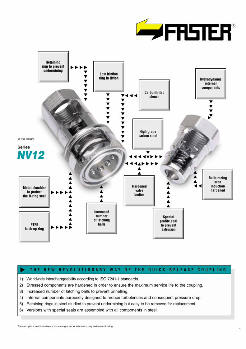
Low frictionring in Nylon
PTFEback-up ring
Metal shoulderto protect
the O-ring seal
Hydrodynamicinternal
components
Hardenedvalve
bodies
Increasednumber
of latchingballs
Specialprofile sealto preventextrusion
Balls racingarea
inductionhardened
High gradecarbon steel
Retainingring to preventundermining
Carbonitritedsleeve
5
Series
NV12
In the picture
The descriptions and illustrations in this catalogue are for information only and are not binding.
1) Worldwide interchangeability according to ISO 7241-1 standards.
2) Stressed components are hardened in order to ensure the maximum service life to the coupling.
3) Increased number of latching balls to prevent brinelling.
4) Internal components purposely designed to reduce turbolences and consequent pressure drop.
5) Retaining rings in steel studied to prevent undermining but easy to be removed for replacement.
6) Versions with special seals are assembled with all components in steel.
T H E N E W R E V O L U T I O N A R Y W A Y O F T H E Q U I C K - R E L E A S E C O U P L I N G
�
� � � �
���
����
� � �
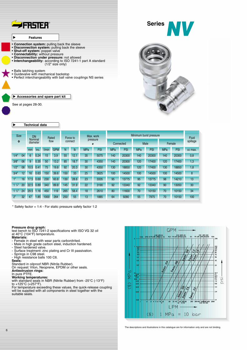
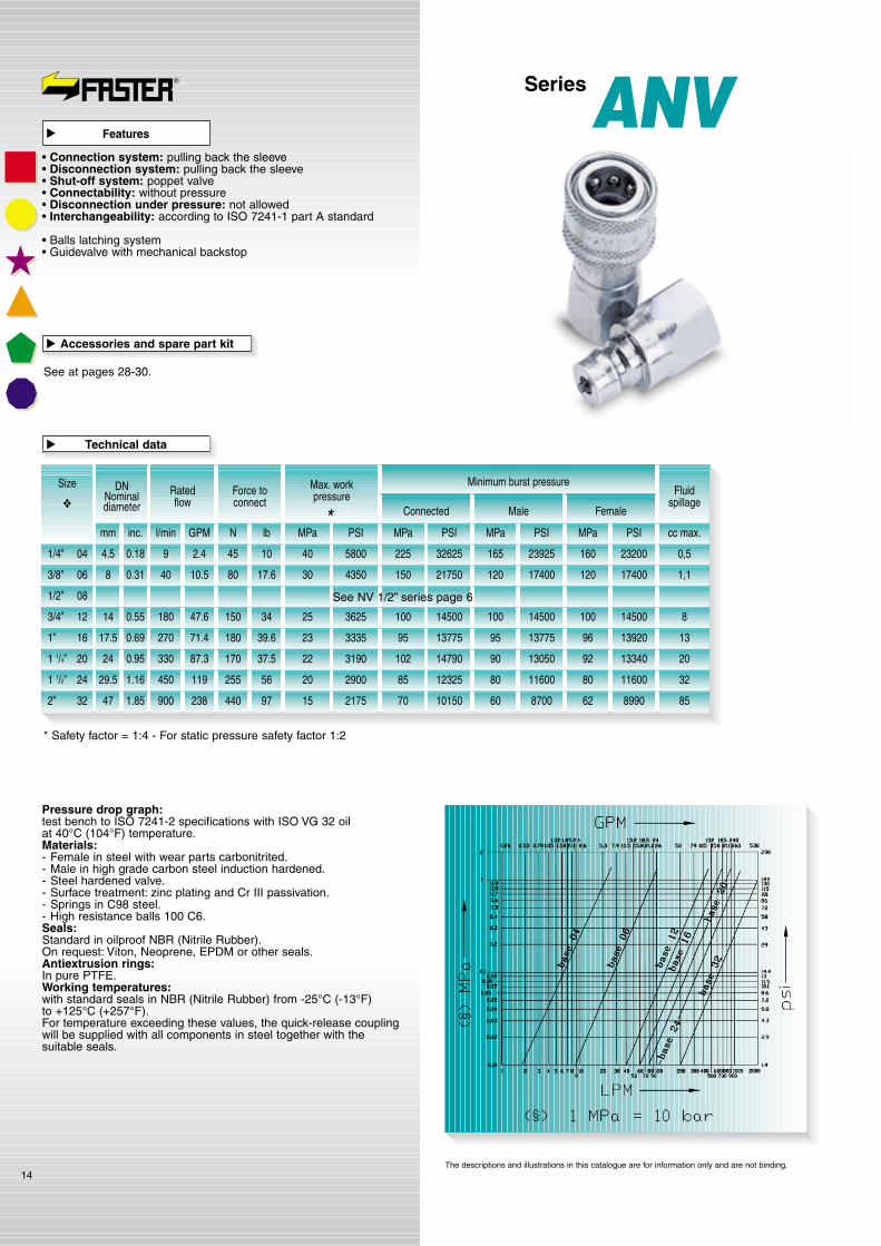
Pressure drop graph:test bench to ISO 7241-2 specifications with ISO VG 32 oilat 40°C (104°F) temperature.Materials:- Female in steel with wear parts carbonitrited.- Male in high grade carbon steel, induction hardened.- Steel hardened valve.- Surface treatment: zinc plating and Cr III passivation.- Springs in C98 steel.- High resistance balls 100 C6.Seals:Standard in oilproof NBR (Nitrile Rubber).On request: Viton, Neoprene, EPDM or other seals.Antiextrusion rings:In pure PTFE.Working temperatures:with standard seals in NBR (Nitrile Rubber) from -25°C (-13°F)to +125°C (+257°F).For temperature exceeding these values, the quick-release couplingwill be supplied with all components in steel together with thesuitable seals.
6
* Safety factor = 1:4 - For static pressure safety factor 1:2
SizeRatedflow
Fluidspillage
Force toconnect
Max. workpressure
Minimum burst pressure
Connected
1/4” 04
3/8” 06
1/2” 08
3/4” 12
1” 16
1 1/4” 20
1 1/2” 24
2” 32
l/min GPM N lb MPa PSI
Male Female
DNNominaldiameter
MPa PSIMPa PSI cc max.MPa PSI
5075
4350
4350
3625
3335
3190
2610
1885
140
140
130
100
95
92
80
64
20300
20300
18850
14500
13775
13340
11600
9280
140
120
120
100
95
92
70
55
20300
17400
17400
14500
13775
13340
10150
7975
140
120
130
100
98
90
70
70
20300
17400
18850
14500
14210
13050
10150
10150
0,8
1,3
1,8
8
13
30
34
100
35
30
30
25
23
22
18
13
15
50
75
150
230
340
450
1000
3.9
13.2
19.8
39.6
60.8
89.8
119
264
12.1
18.7
20.3
33
28.6
31.9
58.4
55
55
85
92
150
130
145
265
250
*
Technical data
�
Accessories and spare part kit
See at pages 28-30.
�
mm inc.
6 0.24
9 0.35
10.5 0.41
16 0.63
17.5 0.69
22.5 0.89
29.5 1.16
47 1.85
❖
SeriesNVFeatures
�
• Connection system: pulling back the sleeve• Disconnection system: pulling back the sleeve• Shut-off system: poppet valve• Connectability: without pressure• Disconnection under pressure: not allowed• Interchangeability: according to ISO 7241-1 part A standard
(1/2” size only)
• Balls latching system• Guidevalve with mechanical backstop• Perfect interchangeability with ball valve couplings NS series
The descriptions and illustrations in this catalogue are for information only and are not binding.
Series NV
7
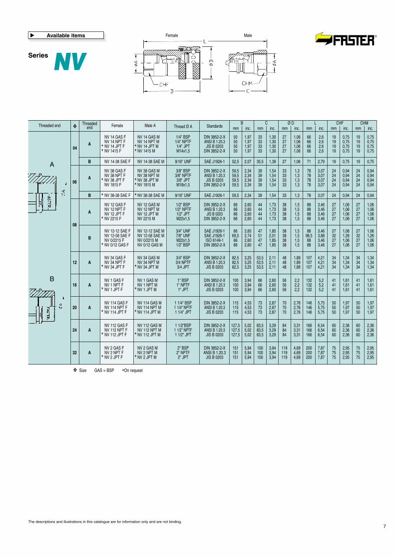
Male A Thread Ø AB
mm inc.C
mm inc.Ø D
mm inc.L
mm inc.CHF
mm inc.CHM
mm inc.Standards❖
NV 14 GAS F NV 14 GAS M 1/4" BSP DIN 3852-2-X 50 1,97 33 1,30 27 1,06 66 2,6 19 0,75 19 0,75NV 14 NPT F NV 14 NPT M 1/4" NPTF ANSI B 1.20.3 50 1,97 33 1,30 27 1,06 66 2,6 19 0,75 19 0,75NV 14 JPT F NV 14 JPT M 1/4" JPT JIS B 0203 50 1,97 33 1,30 27 1,06 66 2,6 19 0,75 19 0,75NV 1415 F NV 1415 M M14x1,5 DIN 3852-2-X 50 1,97 33 1,30 27 1,06 66 2,6 19 0,75 19 0,75
NV 38 GAS F NV 38 GAS M 3/8" BSP DIN 3852-2-X 59,5 2,34 39 1,54 33 1,3 78 3,07 24 0,94 24 0,94NV 38 NPT F NV 38 NPT M 3/8" NPTF ANSI B 1.20.3 59,5 2,34 39 1,54 33 1,3 78 3,07 24 0,94 24 0,94NV 38 JPT F NV 38 JPT M 3/8" JPT JIS B 0203 59,5 2,34 39 1,54 33 1,3 78 3,07 24 0,94 24 0,94NV 1815 F NV 1815 M M18x1,5 DIN 3852-2-X 59,5 2,34 39 1,54 33 1,3 78 3,07 24 0,94 24 0,94
NV 12 GAS F NV 12 GAS M 1/2" BSP DIN 3852-2-X 66 2,60 44 1,73 38 1,5 88 3,46 27 1,06 27 1,06NV 12 NPT F NV 12 NPT M 1/2" NPTF ANSI B 1.20.3 66 2,60 44 1,73 38 1,5 88 3,46 27 1,06 27 1,06NV 12 JPT F NV 12 JPT M 1/2" JPT JIS B 0203 66 2,60 44 1,73 38 1,5 88 3,46 27 1,06 27 1,06NV 2215 F NV 2215 M M22x1,5 DIN 3852-2-X 66 2,60 44 1,73 38 1,5 88 3,46 27 1,06 27 1,06
NV 12-12 SAE F NV 12-12 SAE M 3/4" UNF SAE J1926-1 66 2,60 47 1,85 38 1,5 88 3,46 27 1,06 27 1,06NV 12-58 SAE F NV 12-58 SAE M 7/8" UNF SAE J1926-1 69,5 2,74 51 2,01 38 1,5 98,5 3,88 32 1,26 32 1,26NV 0/2215 F NV 0/2215 M M22x1,5 ISO 6149-1 66 2,60 47 1,85 38 1,5 88 3,46 27 1,06 27 1,06NV 0/12 GAS F NV 0/12 GAS M 1/2” BSP DIN 3852-2-X 66 2,60 47 1,85 38 1,5 88 3,46 27 1,06 27 1,06
NV 34 GAS F NV 34 GAS M 3/4" BSP DIN 3852-2-X 82,5 3,25 53,5 2,11 48 1,89 107 4,21 34 1,34 34 1,34NV 34 NPT F NV 34 NPT M 3/4 NPTF ANSI B 1.20.3 82,5 3,25 53,5 2,11 48 1,89 107 4,21 34 1,34 34 1,34NV 34 JPT F NV 34 JPT M 3/4 JPT JIS B 0203 82,5 3,25 53,5 2,11 48 1,89 107 4,21 34 1,34 34 1,34
NV 1 GAS F NV 1 GAS M 1" BSP DIN 3852-2-X 100 3,94 66 2,60 56 2,2 132 5,2 41 1,61 41 1,61NV 1 NPT F NV 1 NPT M 1" NPTF ANSI B 1.20.3 100 3,94 66 2,60 56 2,2 132 5,2 41 1,61 41 1,61NV 1 JPT F NV 1 JPT M 1" JPT JIS B 0203 100 3,94 66 2,60 56 2,2 132 5,2 41 1,61 41 1,61
NV 114 GAS F NV 114 GAS M 1 1/4" BSP DIN 3852-2-X 115 4,53 73 2,87 70 2,76 146 5,75 50 1,97 50 1,97NV 114 NPT F NV 114 NPT M 1 1/4" NPTF ANSI B 1.20.3 115 4,53 73 2,87 70 2,76 146 5,75 50 1,97 50 1,97NV 114 JPT F NV 114 JPT M 1 1/4" JPT JIS B 0203 115 4,53 73 2,87 70 2,76 146 5,75 50 1,97 50 1,97
NV 112 GAS F NV 112 GAS M 1 1/2"BSP DIN 3852-2-X 127,5 5,02 83,5 3,29 84 3,31 166 6,54 60 2,36 60 2,36NV 112 NPT F NV 112 NPT M 1 1/2" NPTF ANSI B 1.20.3 127,5 5,02 83,5 3,29 84 3,31 166 6,54 60 2,36 60 2,36NV 112 JPT F NV 112 JPT M 1 1/2" JPT JIS B 0203 127,5 5,02 83,5 3,29 84 3,31 166 6,54 60 2,36 60 2,36
NV 2 GAS F NV 2 GAS M 2" BSP DIN 3852-2-X 151 5,94 100 3,94 119 4,69 200 7,87 75 2,95 75 2,95NV 2 NPT F NV 2 NPT M 2" NPTF ANSI B 1.20.3 151 5,94 100 3,94 119 4,69 200 7,87 75 2,95 75 2,95NV 2 JPT F NV 2 JPT M 2" JPT JIS B 0203 151 5,94 100 3,94 119 4,69 200 7,87 75 2,95 75 2,95
NV 14-38 SAE F NV 14-38 SAE M 9/16" UNF SAE J1926-1 52,5 2,07 35,5 1,39 27 1,06 71 2,79 19 0,75 19 0,75
* ** *
* **
ThreadedendThreaded end Female
04A
B
NV 38-38 SAE F NV 38-38 SAE M 9/16" UNF SAE J1926-1 59,5 2,34 39 1,54 33 1,3 78 3,07 24 0,94 24 0,94B
❖
❖ Size GAS = BSP *On request
06A
08
12
16
20
24
32
A
B
A
A
A
A
A
A
B
The descriptions and illustrations in this catalogue are for information only and are not binding.
Available items
�
* *
* *
* *
* *
* *
* *
*
*
MaleFemale
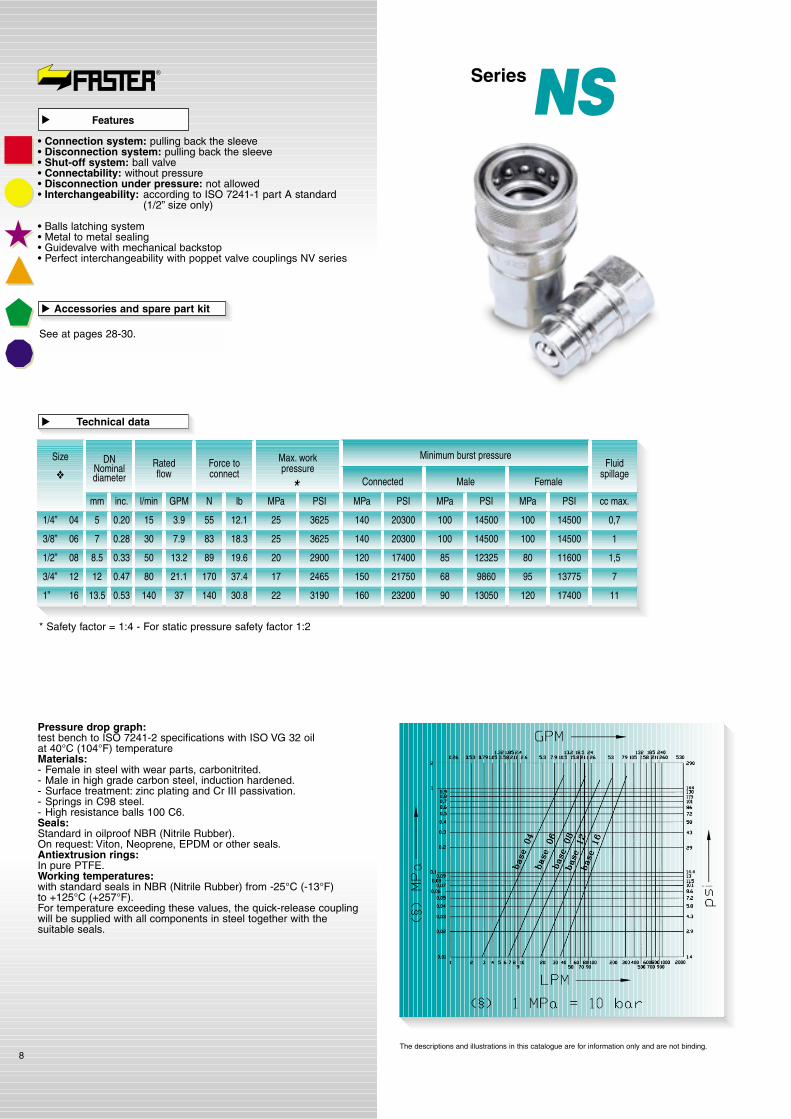
Pressure drop graph:test bench to ISO 7241-2 specifications with ISO VG 32 oilat 40°C (104°F) temperatureMaterials:- Female in steel with wear parts, carbonitrited.- Male in high grade carbon steel, induction hardened.- Surface treatment: zinc plating and Cr III passivation.- Springs in C98 steel.- High resistance balls 100 C6.Seals:Standard in oilproof NBR (Nitrile Rubber).On request: Viton, Neoprene, EPDM or other seals.Antiextrusion rings:In pure PTFE.Working temperatures:with standard seals in NBR (Nitrile Rubber) from -25°C (-13°F)to +125°C (+257°F).For temperature exceeding these values, the quick-release couplingwill be supplied with all components in steel together with thesuitable seals.
8
* Safety factor = 1:4 - For static pressure safety factor 1:2
SizeRatedflow
Fluidspillage
Force toconnect
Max. workpressure
Minimum burst pressure
Connected
1/4” 04
3/8” 06
1/2” 08
3/4” 12
1” 16
l/min GPM N lb MPa PSI
Male Female
DNNominaldiameter
MPa PSIMPa PSI cc max.MPa PSI
3625
3625
2900
2465
3190
140
140
120
150
160
20300
20300
17400
21750
23200
100
100
85
68
90
14500
14500
12325
9860
13050
100
100
80
95
120
14500
14500
11600
13775
17400
0,7
1
1,5
7
11
25
25
20
17
22
15
30
50
80
140
3.9
7.9
13.2
21.1
37
12.1
18.3
19.6
37.4
30.8
55
83
89
170
140
*
Technical data
�
Accessories and spare part kit
See at pages 28-30.
�
mm inc.
5 0.20
7 0.28
8.5 0.33
12 0.47
13.5 0.53
❖
SeriesNSFeatures
�
• Connection system: pulling back the sleeve• Disconnection system: pulling back the sleeve• Shut-off system: ball valve• Connectability: without pressure• Disconnection under pressure: not allowed• Interchangeability: according to ISO 7241-1 part A standard
(1/2” size only)
• Balls latching system• Metal to metal sealing• Guidevalve with mechanical backstop• Perfect interchangeability with poppet valve couplings NV series
The descriptions and illustrations in this catalogue are for information only and are not binding.

Series NS
9
Male Thread Ø AB
mm inc.C
mm inc.Ø D
mm inc.L
mm inc.CHF
mm inc.CHM
mm inc.Standards❖
NS 14 GAS F NS 14 GAS M 1/4" BSP DIN 3852-2-X 50 1,97 33 1,30 27 1,06 66 2,6 19 0,75 19 0,75NS 14 NPT F NS 14 NPT M 1/4" NPTF ANSI B 1.20.3 50 1,97 33 1,30 27 1,06 66 2,6 19 0,75 19 0,75NS 14 JPT F NS 14 JPT M 1/4" JPT JIS B 0203 50 1,97 33 1,30 27 1,06 66 2,6 19 0,75 19 0,75
NS 38 GAS F NS 38 GAS M 3/8" BSP DIN 3852-2-X 59,5 2,34 39 1,54 33 1,3 78 3,07 24 0,94 24 0,94NS 38 NPT F NS 38 NPT M 3/8" NPTF ANSI B 1.20.3 59,5 2,34 39 1,54 33 1,3 78 3,07 24 0,94 24 0,94NS 38 JPT F NS 38 JPT M 3/8" JPT JIS B 0203 59,5 2,34 39 1,54 33 1,3 78 3,07 24 0,94 24 0,94NS 1815 F NS 1815 M M18x1,5 DIN 3852-2-X 59,5 2,34 39 1,54 33 1,3 78 3,07 24 0,94 24 0,94
NS 12 GAS F NS 12 GAS M 1/2" BSP DIN 3852-2-X 68 2,68 46 1,81 38 1,5 88 3,46 27 1,06 27 1,06NS 12 NPT F NS 12 NPT M 1/2" NPTF ANSI B 1.20.3 68 2,68 46 1,81 38 1,5 88 3,46 27 1,06 27 1,06NS 12 JPT F NS 12 JPT M 1/2" JPT JIS B 0203 68 2,68 46 1,81 38 1,5 88 3,46 27 1,06 27 1,06
NS 34 GAS F NS 34 GAS M 3/4" BSP DIN 3852-2-X 82,5 3,25 53,5 2,11 48 1,89 107 4,21 34 1,34 34 1,34NS 34 NPT F NS 34 NPT M 3/4" NPT ANSI B 1.20.3 82,5 3,25 53,5 2,11 48 1,89 107 4,21 34 1,34 34 1,34NS 34 JPT F NS 34 JPT M 3/4" JPT JIS B 0203 82,5 3,25 53,5 2,11 48 1,89 107 4,21 34 1,34 34 1,34
NS 1 GAS F NS 1 GAS M 1" BSP DIN 3852-2-X 100 3,94 66 2,6 56 2,2 132 5,2 41 1,61 41 1,61NS 1 NPT F NS 1 NPT M 1" NPTF ANSI B 1.20.3 100 3,94 66 2,6 56 2,2 132 5,2 41 1,61 41 1,61NS 1 JPT F NS 1 JPT M 1" JPT JIS B 0203 100 3,94 66 2,6 56 2,2 132 5,2 41 1,61 41 1,61
* *
* *
* *
*
*
*
ThreadedendThreaded end Female
04
06
08
12
16
A
A
A
A
A
❖
❖ Size GAS = BSP *On request
The descriptions and illustrations in this catalogue are for information only and are not binding.
Available items
�
A
MaleFemale
Pressure drop graph:test bench to ISO 7241-2 specifications with ISO VG 32 oilat 40°C (104°F) temperature.Materials:- Female in steel with wear parts carbonitrited.- Male in high grade carbon steel, induction hardened.- Surface treatment: zinc plating and Cr III passivation.- Springs in C98 steel.- High resistance balls 100 C6.Seals:Standard in oilproof NBR (Nitrile Rubber).On request: Viton, Neoprene, EPDM or other seals.Antiextrusion rings:In pure PTFE.Working temperatures:with standard seals in NBR (Nitrile Rubber) from -25°C (-13°F)to +125°C (+257°F).For temperatures exceeding these values, the quick-release couplingwill be supplied with all components in steel together with thesuitable seals.
10
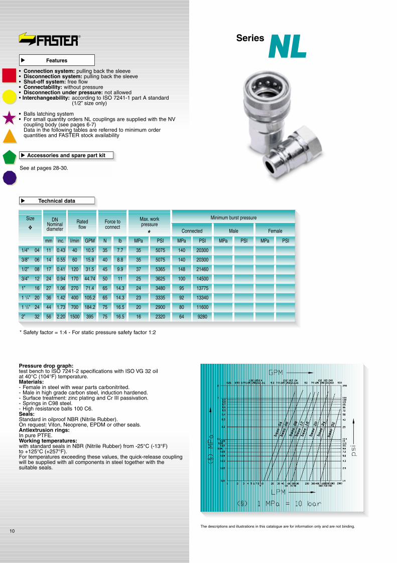
* Safety factor = 1:4 - For static pressure safety factor 1:2
SizeRatedflow
Force toconnect
Max. workpressure
Minimum burst pressure
Connected
1/4” 04
3/8” 06
1/2” 08
3/4” 12
1” 16
1 1/4” 20
1 1/2” 24
2” 32
l/min GPM N lb MPa PSI
Male Female
DNNominaldiameter
MPa PSIMPa PSIMPa PSI
5075
5075
5365
3625
3480
3335
2900
2320
140
140
148
100
95
92
80
64
20300
20300
21460
14500
13775
13340
11600
9280
35
35
37
25
24
23
20
16
40
60
120
170
270
400
700
1500
10.5
15.8
31.5
44.74
71.4
105.2
184.2
395
7.7
8.8
9.9
11
14.3
14.3
16.5
16.5
35
40
45
50
65
65
75
75
*
Technical data
�
Accessories and spare part kit
See at pages 28-30.
�
mm inc.
11 0.43
14 0.55
17 0.41
24 0.94
27 1.06
36 1.42
44 1.73
56 2.20
❖
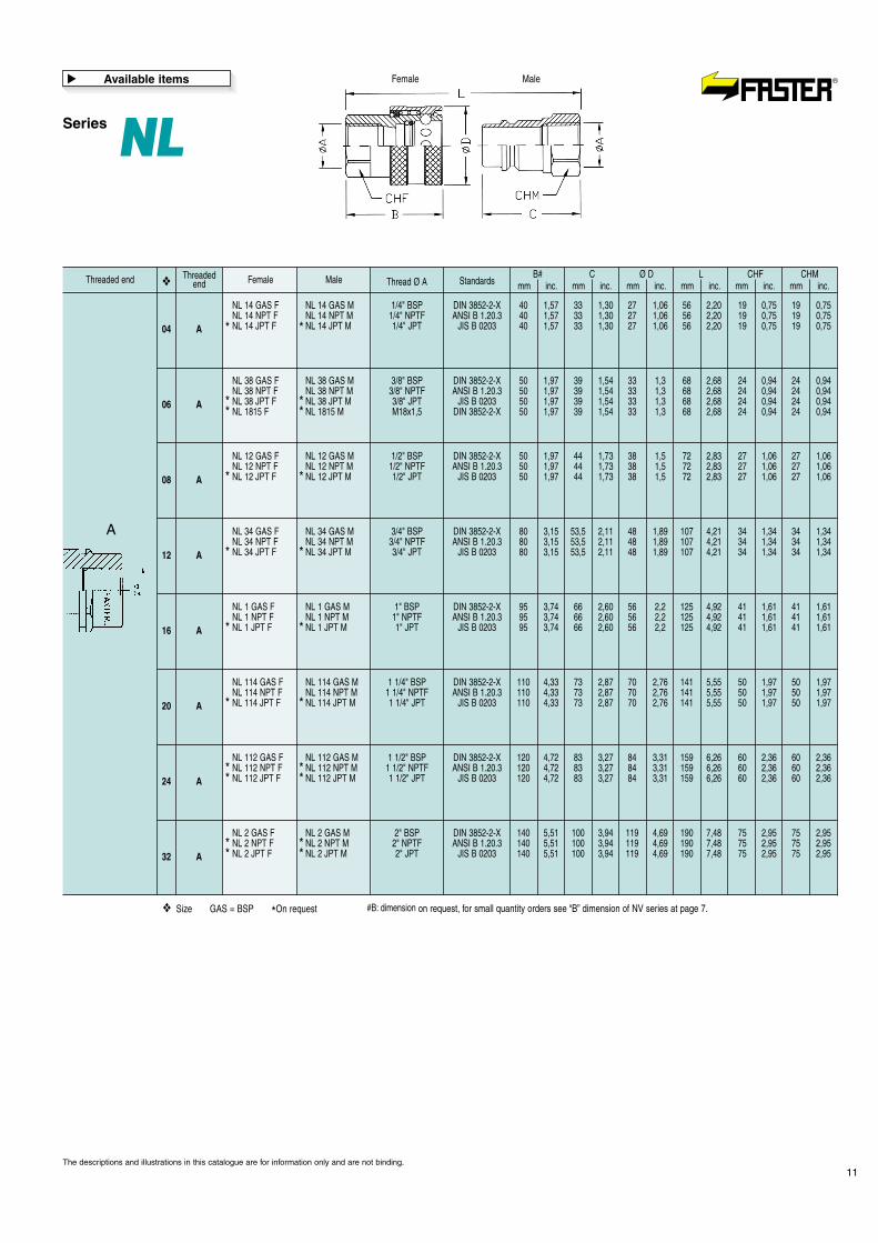
SeriesNLFeatures
�
• Connection system: pulling back the sleeve• Disconnection system: pulling back the sleeve• Shut-off system: free flow• Connectability: without pressure• Disconnection under pressure: not allowed• Interchangeability: according to ISO 7241-1 part A standard
(1/2” size only)
• Balls latching system• For small quantity orders NL couplings are supplied with the NV
coupling body (see pages 6-7)Data in the following tables are referred to minimum orderquantities and FASTER stock availability
The descriptions and illustrations in this catalogue are for information only and are not binding.
Series NL
11
Male Thread Ø AB#
mm inc.C
mm inc.Ø D
mm inc.L
mm inc.CHF
mm inc.CHM
mm inc.Standards❖
NL 14 GAS F NL 14 GAS M 1/4" BSP DIN 3852-2-X 40 1,57 33 1,30 27 1,06 56 2,20 19 0,75 19 0,75NL 14 NPT F NL 14 NPT M 1/4" NPTF ANSI B 1.20.3 40 1,57 33 1,30 27 1,06 56 2,20 19 0,75 19 0,75NL 14 JPT F NL 14 JPT M 1/4" JPT JIS B 0203 40 1,57 33 1,30 27 1,06 56 2,20 19 0,75 19 0,75* *
ThreadedendThreaded end Female
04 A
NL 38 GAS F NL 38 GAS M 3/8" BSP DIN 3852-2-X 50 1,97 39 1,54 33 1,3 68 2,68 24 0,94 24 0,94NL 38 NPT F NL 38 NPT M 3/8" NPTF ANSI B 1.20.3 50 1,97 39 1,54 33 1,3 68 2,68 24 0,94 24 0,94NL 38 JPT F NL 38 JPT M 3/8" JPT JIS B 0203 50 1,97 39 1,54 33 1,3 68 2,68 24 0,94 24 0,94NL 1815 F NL 1815 M M18x1,5 DIN 3852-2-X 50 1,97 39 1,54 33 1,3 68 2,68 24 0,94 24 0,94
06 A
NL 12 GAS F NL 12 GAS M 1/2" BSP DIN 3852-2-X 50 1,97 44 1,73 38 1,5 72 2,83 27 1,06 27 1,06NL 12 NPT F NL 12 NPT M 1/2" NPTF ANSI B 1.20.3 50 1,97 44 1,73 38 1,5 72 2,83 27 1,06 27 1,06NL 12 JPT F NL 12 JPT M 1/2" JPT JIS B 0203 50 1,97 44 1,73 38 1,5 72 2,83 27 1,06 27 1,0608 A
NL 34 GAS F NL 34 GAS M 3/4" BSP DIN 3852-2-X 80 3,15 53,5 2,11 48 1,89 107 4,21 34 1,34 34 1,34NL 34 NPT F NL 34 NPT M 3/4" NPTF ANSI B 1.20.3 80 3,15 53,5 2,11 48 1,89 107 4,21 34 1,34 34 1,34NL 34 JPT F NL 34 JPT M 3/4" JPT JIS B 0203 80 3,15 53,5 2,11 48 1,89 107 4,21 34 1,34 34 1,3412 A
NL 1 GAS F NL 1 GAS M 1" BSP DIN 3852-2-X 95 3,74 66 2,60 56 2,2 125 4,92 41 1,61 41 1,61NL 1 NPT F NL 1 NPT M 1" NPTF ANSI B 1.20.3 95 3,74 66 2,60 56 2,2 125 4,92 41 1,61 41 1,61NL 1 JPT F NL 1 JPT M 1" JPT JIS B 0203 95 3,74 66 2,60 56 2,2 125 4,92 41 1,61 41 1,6116 A
NL 114 GAS F NL 114 GAS M 1 1/4" BSP DIN 3852-2-X 110 4,33 73 2,87 70 2,76 141 5,55 50 1,97 50 1,97NL 114 NPT F NL 114 NPT M 1 1/4" NPTF ANSI B 1.20.3 110 4,33 73 2,87 70 2,76 141 5,55 50 1,97 50 1,97NL 114 JPT F NL 114 JPT M 1 1/4" JPT JIS B 0203 110 4,33 73 2,87 70 2,76 141 5,55 50 1,97 50 1,9720 A
NL 112 GAS F NL 112 GAS M 1 1/2" BSP DIN 3852-2-X 120 4,72 83 3,27 84 3,31 159 6,26 60 2,36 60 2,36NL 112 NPT F NL 112 NPT M 1 1/2" NPTF ANSI B 1.20.3 120 4,72 83 3,27 84 3,31 159 6,26 60 2,36 60 2,36NL 112 JPT F NL 112 JPT M 1 1/2" JPT JIS B 0203 120 4,72 83 3,27 84 3,31 159 6,26 60 2,36 60 2,3624 A
NL 2 GAS F NL 2 GAS M 2" BSP DIN 3852-2-X 140 5,51 100 3,94 119 4,69 190 7,48 75 2,95 75 2,95NL 2 NPT F NL 2 NPT M 2" NPTF ANSI B 1.20.3 140 5,51 100 3,94 119 4,69 190 7,48 75 2,95 75 2,95NL 2 JPT F NL 2 JPT M 2" JPT JIS B 0203 140 5,51 100 3,94 119 4,69 190 7,48 75 2,95 75 2,9532 A
❖
❖ Size GAS = BSP *On request #B: dimension on request, for small quantity orders see “B” dimension of NV series at page 7.
The descriptions and illustrations in this catalogue are for information only and are not binding.
Available items
�
* *
* *
* *
* *
* *
* ** *
* ** *
* *
A
MaleFemale

Pressure drop graph:test bench to ISO 7241-2 specifications with ISO VG 32 oilat 40°C (104°F) temperature.Materials:- Female in steel with wear parts carbonitrited.- Male in high grade carbon steel, induction hardened.- Steel hardened valve.- Surface treatment: zinc plating and Cr III passivation.- Springs in C98 steel.- High resistance balls 100 C6.Seals:Standard in oilproof NBR (Nitrile Rubber).On request: Viton, Neoprene, EPDM or other seals.Antiextrusion rings:In pure PTFE.Working temperatures:with standard seals in NBR (Nitrile Rubber) from -25°C (-13°F)to +125°C (+257°F).For temperature exceeding these values, the quick-release couplingwill be supplied with all components in steel together with thesuitable seals.
12
Accessories and spare part kit
See at pages 28-30.
�
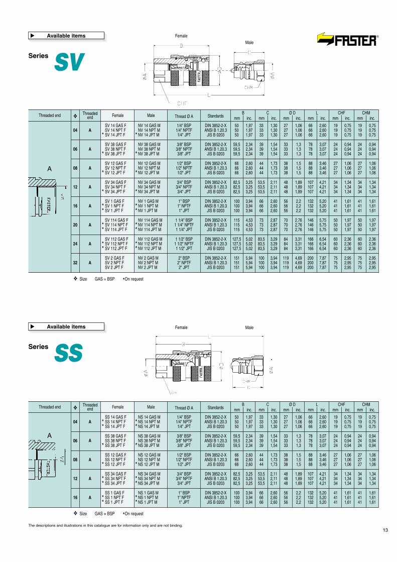
SeriesSV - SSFeatures
�
• Connection system: pulling back the sleeve• Disconnection system: pulling back the sleeve• Shut-off system: poppet valve (SV series)
or ball valve (SS series)• Connectability: without pressure• Disconnection under pressure: not allowed• Interchangeability: according to ISO 7241-1 part A standard
(1/2” size only)
• Balls latching system• Additional safety sleeve to prevent accidental disconnection• Perfect interchangeability with NV and NS series couplings
The descriptions and illustrations in this catalogue are for information only and are not binding.
Pressure drop graph
SV: see NV series at page 6
SS: see NS series at page 8
* Safety factor = 1:4 - For static pressure safety factor 1:2
SizeRatedflow
Fluidspillage
Force toconnect
Max. workpressure
Minimum burst pressure
Connected
1/4” 04
3/8” 06
1/2” 08
3/4” 12
1” 16
1 1/4” 20
1 1/2” 24
2” 32
l/min GPM N lb MPa PSI
Male Female
DNNominaldiameter
MPa PSIMPa PSI cc max.MPa PSI
5075
4350
4350
3625
3335
3190
2610
1885
140
140
130
100
95
92
80
64
20300
20300
18850
14500
13775
13340
11600
9280
140
120
120
100
95
92
70
55
20300
17400
17400
14500
13775
13340
10150
7975
140
120
130
100
98
90
70
70
20300
17400
18850
14500
14210
13050
10150
10150
0,8
1,3
1,8
8
13
30
34
100
35
30
30
25
23
22
18
13
15
50
75
150
230
340
450
1000
3.9
13.2
19.8
39.6
60.8
89.8
119
264
12.1
18.7
20.3
33
28.6
31.9
58.4
55
55
85
92
150
130
145
265
250
*
Technical data
�
mm inc.
6 0.24
9 0.35
10.5 0.41
16 0.63
17.5 0.69
22.5 0.89
29.5 1.16
47 1.85
1/4” 04 3625 140 20300 100 14500 100 14500 0,72515 3.9 12.1555 0.20
3/8” 06 3625 140 20300 100 14500 100 14500 12530 7.9 18.3837 0.28
1/2” 08 2900 120 17400 85 12325 80 11600 22050 13.2 19.6898.5 0.41
3/4” 12 2465 150 21750 68 9860 95 13775 71780 21.1 37,417012 0.47
1” 16 3190 160 23200 90 13050 120 17400 1122140 37 30,814013.5 0.53
❖
Patent Application Pending
Serie
sS
VS
S
MaleFemale
Series SV
13
Male Thread Ø AB
mm inc.C
mm inc.Ø D
mm inc.L
mm inc.CHF
mm inc.CHM
mm inc.Standards❖
SV 14 GAS F NV 14 GAS M 1/4" BSP DIN 3852-2-X 50 1,97 33 1,30 27 1,06 66 2,60 19 0,75 19 0,75SV 14 NPT F NV 14 NPT M 1/4" NPTF ANSI B 1.20.3 50 1,97 33 1,30 27 1,06 66 2,60 19 0,75 19 0,75SV 14 JPT F NV 14 JPT M 1/4" JPT JIS B 0203 50 1,97 33 1,30 27 1,06 66 2,60 19 0,75 19 0,75* *
ThreadedendThreaded end Female
04 A
SV 38 GAS F NV 38 GAS M 3/8" BSP DIN 3852-2-X 59,5 2,34 39 1,54 33 1,3 78 3,07 24 0,94 24 0,94SV 38 NPT F NV 38 NPT M 3/8" NPTF ANSI B 1.20.3 59,5 2,34 39 1,54 33 1,3 78 3,07 24 0,94 24 0,94SV 38 JPT F NV 38 JPT M 3/8" JPT JIS B 0203 59,5 2,34 39 1,54 33 1,3 78 3,07 24 0,94 24 0,94
SV 12 GAS F NV 12 GAS M 1/2" BSP DIN 3852-2-X 66 2,60 44 1,73 38 1,5 88 3,46 27 1,06 27 1,06SV 12 NPT F NV 12 NPT M 1/2" NPTF ANSI B 1.20.3 66 2,60 44 1,73 38 1,5 88 3,46 27 1,06 27 1,06SV 12 JPT F NV 12 JPT M 1/2" JPT JIS B 0203 66 2,60 44 1,73 38 1,5 88 3,46 27 1,06 27 1,06
SV 34 GAS F NV 34 GAS M 3/4" BSP DIN 3852-2-X 82,5 3,25 53,5 2,11 48 1,89 107 4,21 34 1,34 34 1,34SV 34 NPT F NV 34 NPT M 3/4" NPTF ANSI B 1.20.3 82,5 3,25 53,5 2,11 48 1,89 107 4,21 34 1,34 34 1,34SV 34 JPT F NV 34 JPT M 3/4" JPT JIS B 0203 82,5 3,25 53,5 2,11 48 1,89 107 4,21 34 1,34 34 1,34
SV 1 GAS F NV 1 GAS M 1" BSP DIN 3852-2-X 100 3,94 66 2,60 56 2,2 132 5,20 41 1,61 41 1,61SV 1 NPT F NV 1 NPT M 1" NPTF ANSI B 1.20.3 100 3,94 66 2,60 56 2,2 132 5,20 41 1,61 41 1,61SV 1 JPT F NV 1 JPT M 1" JPT JIS B 0203 100 3,94 66 2,60 56 2,2 132 5,20 41 1,61 41 1,61
SV 114 GAS F NV 114 GAS M 1 1/4" BSP DIN 3852-2-X 115 4,53 73 2,87 70 2,76 146 5,75 50 1,97 50 1,97SV 114 NPT F NV 114 NPT M 1 1/4" NPTF ANSI B 1.20.3 115 4,53 73 2,87 70 2,76 146 5,75 50 1,97 50 1,97SV 114 JPT F NV 114 JPT M 1 1/4" JPT JIS B 0203 115 4,53 73 2,87 70 2,76 146 5,75 50 1,97 50 1,97
SV 112 GAS F NV 112 GAS M 1 1/2" BSP DIN 3852-2-X 127,5 5,02 83,5 3,29 84 3,31 166 6,54 60 2,36 60 2,36SV 112 NPT F NV 112 NPT M 1 1/2" NPTF ANSI B 1.20.3 127,5 5,02 83,5 3,29 84 3,31 166 6,54 60 2,36 60 2,36SV 112 JPT F NV 112 JPT M 1 1/2" JPT JIS B 0203 127,5 5,02 83,5 3,29 84 3,31 166 6,54 60 2,36 60 2,36
SV 2 GAS F NV 2 GAS M 2" BSP DIN 3852-2-X 151 5,94 100 3,94 119 4,69 200 7,87 75 2,95 75 2,95SV 2 NPT F NV 2 NPT M 2" NPTF ANSI B 1.20.3 151 5,94 100 3,94 119 4,69 200 7,87 75 2,95 75 2,95SV 2 JPT F NV 2 JPT M 2" JPT JIS B 0203 151 5,94 100 3,94 119 4,69 200 7,87 75 2,95 75 2,95
06
08
12
16
20
24
32
A
A
A
A
A
A
A
❖
❖ Size GAS = BSP *On request
The descriptions and illustrations in this catalogue are for information only and are not binding.
Available items
�
MaleFemale
Series SSAvailable items
�
A
* *
* *
* *
* ** *
* ** *
* ** *
Male Thread Ø AB
mm inc.C
mm inc.Ø D
mm inc.L
mm inc.CHF
mm inc.CHM
mm inc.Standards❖
SS 14 GAS F NS 14 GAS M 1/4" BSP DIN 3852-2-X 50 1,97 33 1,30 27 1,06 66 2,60 19 0,75 19 0,75SS 14 NPT F NS 14 NPT M 1/4" NPTF ANSI B 1.20.3 50 1,97 33 1,30 27 1,06 66 2,60 19 0,75 19 0,75SS 14 JPT F NS 14 JPT M 1/4" JPT JIS B 0203 50 1,97 33 1,30 27 1,06 66 2,60 19 0,75 19 0,75* *
* *
ThreadedendThreaded end Female
04 A
SS 38 GAS F NS 38 GAS M 3/8" BSP DIN 3852-2-X 59,5 2,34 39 1,54 33 1,3 78 3,07 24 0,94 24 0,94SS 38 NPT F NS 38 NPT M 3/8" NPTF ANSI B 1.20.3 59,5 2,34 39 1,54 33 1,3 78 3,07 24 0,94 24 0,94SS 38 JPT F NS 38 JPT M 3/8" JPT JIS B 0203 59,5 2,34 39 1,54 33 1,3 78 3,07 24 0,94 24 0,94
SS 12 GAS F NS 12 GAS M 1/2" BSP DIN 3852-2-X 66 2,60 44 1,73 38 1,5 88 3,46 27 1,06 27 1,06SS 12 NPT F NS 12 NPT M 1/2" NPTF ANSI B 1.20.3 66 2,60 44 1,73 38 1,5 88 3,46 27 1,06 27 1,06SS 12 JPT F NS 12 JPT M 1/2" JPT JIS B 0203 66 2,60 44 1,73 38 1,5 88 3,46 27 1,06 27 1,06
SS 34 GAS F NS 34 GAS M 3/4" BSP DIN 3852-2-X 82,5 3,25 53,5 2,11 48 1,89 107 4,21 34 1,34 34 1,34SS 34 NPT F NS 34 NPT M 3/4" NPTF ANSI B 1.20.3 82,5 3,25 53,5 2,11 48 1,89 107 4,21 34 1,34 34 1,34SS 34 JPT F NS 34 JPT M 3/4" JPT JIS B 0203 82,5 3,25 53,5 2,11 48 1,89 107 4,21 34 1,34 34 1,34
SS 1 GAS F NS 1 GAS M 1" BSP DIN 3852-2-X 100 3,94 66 2,60 56 2,2 132 5,20 41 1,61 41 1,61SS 1 NPT F NS 1 NPT M 1" NPTF ANSI B 1.20.3 100 3,94 66 2,60 56 2,2 132 5,20 41 1,61 41 1,61SS 1 JPT F NS 1 JPT M 1" JPT JIS B 0203 100 3,94 66 2,60 56 2,2 132 5,20 41 1,61 41 1,61
06
08
12
16
A
A
A
A
❖
❖ Size GAS = BSP *On request
* *
* *
* ** *
* ** *
A
Pressure drop graph:test bench to ISO 7241-2 specifications with ISO VG 32 oilat 40°C (104°F) temperature.Materials:- Female in steel with wear parts carbonitrited.- Male in high grade carbon steel induction hardened.- Steel hardened valve.- Surface treatment: zinc plating and Cr III passivation.- Springs in C98 steel.- High resistance balls 100 C6.Seals:Standard in oilproof NBR (Nitrile Rubber).On request: Viton, Neoprene, EPDM or other seals.Antiextrusion rings:In pure PTFE.Working temperatures:with standard seals in NBR (Nitrile Rubber) from -25°C (-13°F)to +125°C (+257°F).For temperature exceeding these values, the quick-release couplingwill be supplied with all components in steel together with thesuitable seals.
14
* Safety factor = 1:4 - For static pressure safety factor 1:2
SizeRatedflow
Fluidspillage
Force toconnect
Max. workpressure
Minimum burst pressure
Connected
1/4” 04
3/8” 06
1/2” 08
3/4” 12
1” 16
1 1/4” 20
1 1/2” 24
2” 32
l/min GPM N lb MPa PSI
Male Female
DNNominaldiameter
MPa PSIMPa PSI cc max.MPa PSI
5800
4350
3625
3335
3190
2900
2175
225
150
100
95
102
85
70
32625
21750
14500
13775
14790
12325
10150
165
120
100
95
90
80
60
23925
17400
14500
13775
13050
11600
8700
160
120
100
96
92
80
62
23200
17400
14500
13920
13340
11600
8990
0,5
1,1
8
13
20
32
85
40
30
25
23
22
20
15
9
40
180
270
330
450
900
2.4
10.5
47.6
71.4
87.3
119
238
10
17.6
34
39.6
37.5
56
97
45
80
150
180
170
255
440
*
Technical data
�
Accessories and spare part kit
See at pages 28-30.
�
mm inc.
4.5 0.18
8 0.31
14 0.55
17.5 0.69
24 0.95
29.5 1.16
47 1.85
❖
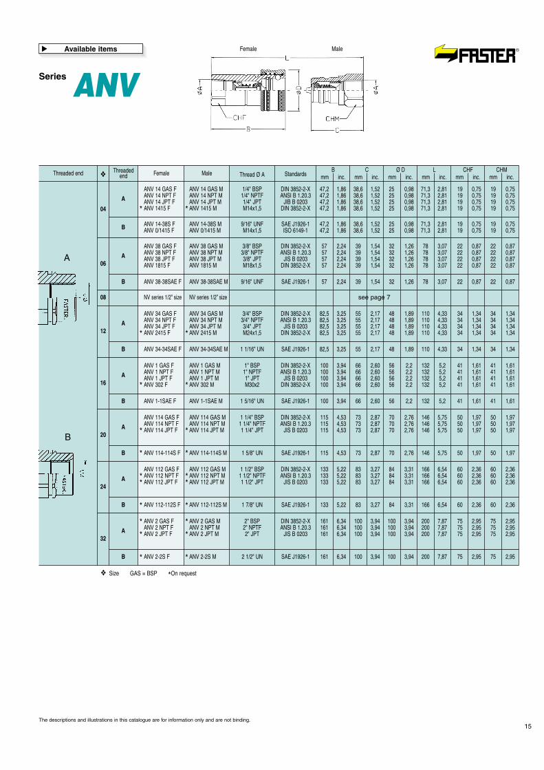
SeriesANVFeatures
�
• Connection system: pulling back the sleeve• Disconnection system: pulling back the sleeve• Shut-off system: poppet valve• Connectability: without pressure• Disconnection under pressure: not allowed• Interchangeability: according to ISO 7241-1 part A standard
• Balls latching system• Guidevalve with mechanical backstop
The descriptions and illustrations in this catalogue are for information only and are not binding.
See NV 1/2” series page 6
Series ANV
15
Male Thread Ø AB
mm inc.C
mm inc.Ø D
mm inc.L
mm inc.CHF
mm inc.CHM
mm inc.Standards❖
ANV 14 GAS F ANV 14 GAS M 1/4" BSP DIN 3852-2-X 47,2 1,86 38,6 1,52 25 0,98 71,3 2,81 19 0,75 19 0,75ANV 14 NPT F ANV 14 NPT M 1/4" NPTF ANSI B 1.20.3 47,2 1,86 38,6 1,52 25 0,98 71,3 2,81 19 0,75 19 0,75ANV 14 JPT F ANV 14 JPT M 1/4" JPT JIB B 0203 47,2 1,86 38,6 1,52 25 0,98 71,3 2,81 19 0,75 19 0,75ANV 1415 F ANV 1415 M M14x1,5 DIN 3852-2-X 47,2 1,86 38,6 1,52 25 0,98 71,3 2,81 19 0,75 19 0,75
ANV 14-38S F ANV 14-38S M 9/16" UNF SAE J1926-1 47,2 1,86 38,6 1,52 25 0,98 71,3 2,81 19 0,75 19 0,75ANV 0/1415 F ANV 0/1415 M M14x1,5 ISO 6149-1 47,2 1,86 38,6 1,52 25 0,98 71,3 2,81 19 0,75 19 0,75
* *
ThreadedendThreaded end Female
04
06
08
12
16
20
24
32
A
ANV 38 GAS F ANV 38 GAS M 3/8" BSP DIN 3852-2-X 57 2,24 39 1,54 32 1,26 78 3,07 22 0,87 22 0,87ANV 38 NPT F ANV 38 NPT M 3/8" NPTF ANSI B 1.20.3 57 2,24 39 1,54 32 1,26 78 3,07 22 0,87 22 0,87ANV 38 JPT F ANV 38 JPT M 3/8" JPT JIS B 0203 57 2,24 39 1,54 32 1,26 78 3,07 22 0,87 22 0,87ANV 1815 F ANV 1815 M M18x1,5 DIN 3852-2-X 57 2,24 39 1,54 32 1,26 78 3,07 22 0,87 22 0,87
ANV 34 GAS F ANV 34 GAS M 3/4" BSP DIN 3852-2-X 82,5 3,25 55 2,17 48 1,89 110 4,33 34 1,34 34 1,34ANV 34 NPT F ANV 34 NPT M 3/4" NPTF ANSI B 1.20.3 82,5 3,25 55 2,17 48 1,89 110 4,33 34 1,34 34 1,34ANV 34 JPT F ANV 34 JPT M 3/4" JPT JIS B 0203 82,5 3,25 55 2,17 48 1,89 110 4,33 34 1,34 34 1,34ANV 2415 F ANV 2415 M M24x1,5 DIN 3852-2-X 82,5 3,25 55 2,17 48 1,89 110 4,33 34 1,34 34 1,34
ANV 1 GAS F ANV 1 GAS M 1" BSP DIN 3852-2-X 100 3,94 66 2,60 56 2,2 132 5,2 41 1,61 41 1,61ANV 1 NPT F ANV 1 NPT M 1" NPTF ANSI B 1.20.3 100 3,94 66 2,60 56 2,2 132 5,2 41 1,61 41 1,61ANV 1 JPT F ANV 1 JPT M 1" JPT JIS B 0203 100 3,94 66 2,60 56 2,2 132 5,2 41 1,61 41 1,61ANV 302 F ANV 302 M M30x2 DIN 3852-2-X 100 3,94 66 2,60 56 2,2 132 5,2 41 1,61 41 1,61
ANV 114 GAS F ANV 114 GAS M 1 1/4" BSP DIN 3852-2-X 115 4,53 73 2,87 70 2,76 146 5,75 50 1,97 50 1,97ANV 114 NPT F ANV 114 NPT M 1 1/4" NPTF ANSI B 1.20.3 115 4,53 73 2,87 70 2,76 146 5,75 50 1,97 50 1,97ANV 114 JPT F ANV 114 JPT M 1 1/4" JPT JIS B 0203 115 4,53 73 2,87 70 2,76 146 5,75 50 1,97 50 1,97
ANV 112 GAS F ANV 112 GAS M 1 1/2" BSP DIN 3852-2-X 133 5,22 83 3,27 84 3,31 166 6,54 60 2,36 60 2,36ANV 112 NPT F ANV 112 NPT M 1 1/2" NPTF ANSI B 1.20.3 133 5,22 83 3,27 84 3,31 166 6,54 60 2,36 60 2,36ANV 112 JPT F ANV 112 JPT M 1 1/2" JPT JIS B 0203 133 5,22 83 3,27 84 3,31 166 6,54 60 2,36 60 2,36
ANV 2 GAS F ANV 2 GAS M 2" BSP DIN 3852-2-X 161 6,34 100 3,94 100 3,94 200 7,87 75 2,95 75 2,95ANV 2 NPT F ANV 2 NPT M 2" NPTF ANSI B 1.20.3 161 6,34 100 3,94 100 3,94 200 7,87 75 2,95 75 2,95ANV 2 JPT F ANV 2 JPT M 2" JPT JIS B 0203 161 6,34 100 3,94 100 3,94 200 7,87 75 2,95 75 2,95
A
A
A
A
A
A
B
ANV 38-38SAE F ANV 38-38SAE M 9/16" UNF SAE J1926-1 57 2,24 39 1,54 32 1,26 78 3,07 22 0,87 22 0,87
ANV 34-34SAE F ANV 34-34SAE M 1 1/16" UN SAE J1926-1 82,5 3,25 55 2,17 48 1,89 110 4,33 34 1,34 34 1,34
ANV 1-1SAE F ANV 1-1SAE M 1 5/16" UN SAE J1926-1 100 3,94 66 2,60 56 2,2 132 5,2 41 1,61 41 1,61
ANV 114-114S F ANV 114-114S M 1 5/8" UN SAE J1926-1 115 4,53 73 2,87 70 2,76 146 5,75 50 1,97 50 1,97
ANV 112-112S F ANV 112-112S M 1 7/8" UN SAE J1926-1 133 5,22 83 3,27 84 3,31 166 6,54 60 2,36 60 2,36
ANV 2-2S F ANV 2-2S M 2 1/2" UN SAE J1926-1 161 6,34 100 3,94 100 3,94 200 7,87 75 2,95 75 2,95
NV series 1/2” size NV series 1/2” size
B
B
B
B
B
B
❖
❖ Size GAS = BSP *On request
The descriptions and illustrations in this catalogue are for information only and are not binding.
Available items
�
* *
* *
* *
* ** *
* ** *
* *
* *
* *
B
A
MaleFemale
see page 7
For more details, please contact FasterResearch & Development Dept.
Pressure drop graph:test bench to ISO 7241-2 specifications with ISO VG 32 oilat 40°C (104°F) temperature.Materials:- Female in steel with wear parts carbonitrited.- Male in high grade carbon steel, induction hardened.- Steel hardened valve.- Surface treatment: zinc plating and Cr III passivation.- Springs in C98 steel.- High resistance balls 100 C6.Seals:Standard in oilproof NBR (Nitrile Rubber).On request: Viton, Neoprene, EPDM or other seals.Antiextrusion rings:In pure PTFE.Working temperatures:with standard seals in NBR (Nitrile Rubber) from -25°C (-13°F)to +125°C (+257°F).For temperature exceeding these values, the quick-release couplingwill be supplied with all components in steel together with thesuitable seals.
16
Accessories and spare part kit
See at pages 28-30.
�
Special versions
�
SeriesHNV
SeriesHNV SeriesHSV
Features
�
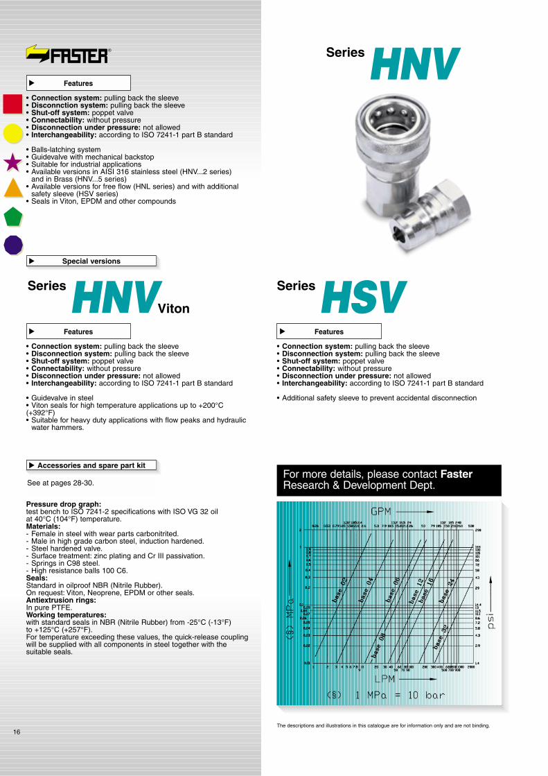
• Connection system: pulling back the sleeve• Disconnction system: pulling back the sleeve• Shut-off system: poppet valve• Connectability: without pressure• Disconnection under pressure: not allowed• Interchangeability: according to ISO 7241-1 part B standard
• Balls-latching system• Guidevalve with mechanical backstop• Suitable for industrial applications• Available versions in AISI 316 stainless steel (HNV...2 series)
and in Brass (HNV...5 series)• Available versions for free flow (HNL series) and with additional
safety sleeve (HSV series)• Seals in Viton, EPDM and other compounds
Features
�
• Connection system: pulling back the sleeve• Disconnection system: pulling back the sleeve• Shut-off system: poppet valve• Connectability: without pressure• Disconnection under pressure: not allowed• Interchangeability: according to ISO 7241-1 part B standard
• Guidevalve in steel• Viton seals for high temperature applications up to +200°C(+392°F)• Suitable for heavy duty applications with flow peaks and hydraulic
water hammers.
Features
�
• Connection system: pulling back the sleeve• Disconnection system: pulling back the sleeve• Shut-off system: poppet valve• Connectability: without pressure• Disconnection under pressure: not allowed• Interchangeability: according to ISO 7241-1 part B standard
• Additional safety sleeve to prevent accidental disconnection
The descriptions and illustrations in this catalogue are for information only and are not binding.
Viton

The descriptions and illustrations in this catalogue are for information only and are not binding.
* Safety factor = 1:4 - For static pressure safety factor 1:2
Ratedflow
Fluidspillage
Force toconnect
Max. workpressure
Minimum burst pressure
Connected
l/min GPM N lb MPa PSI
Male Female
MPa PSIMPa PSI cc max.MPa PSI
5800 230 33350 160 23200 160 23200 0,5407 1.8 14.365
*mm inc.
4.5 0.2
5075 155 22475 140 20300 170 24650 1,03516 4.2 14.3656 0.2
4640 180 26100 130 18850 140 20300 1,53260 15.9 17.6809 0.4
4350 150 21750 125 18125 130 18850 2,83075 19.8 20.39210.5 0.4
3625 100 14500 110 15950 100 14500 1025190 30.3 26.412016 0.6
3335 106 15370 84 12180 90 13050 1323270 71.4 39.618017.5 0.7
2030 60 8700 56 8120 57 8265 8014750 198.4 40.718538 1.5
1305 45 6525 38 5510 40 5800 16091600 423.3 35.216050 2
Female Male
Technical data
�
Size
1/8” 02
1/4” 04
3/8” 06
1/2” 08
3/4” 12
1” 16
1 1/2” 24
2” 32
❖
DNNominaldiameter
Series HNV
17
Male Thread Ø AB
mm inc.C
mm inc.Ø D
mm inc.L
mm inc.CHF
mm inc.CHM
mm inc.Standards❖
HNV 18 GAS F HNV 18 GAS M 1/8" BSP DIN 3852-2-X 50 1,97 31,5 1,24 23 0,91 63 2,48 18 0,71 17 0,67HNV 18 NPT F HNV 18 NPT M 1/8" NPT ANSI B 1.20.3 50 1,97 31,5 1,24 23 0,91 63 2,48 18 0,71 17 0,67
HNV 14 GAS F HNV 14 GAS M 1/4" BSP DIN 3852-2-X 56 2,20 35 1,38 28 1,1 70 2,76 19 0,75 19 0,75HNV 14 NPT F HNV 14 NPT M 1/4" NPT ANSI B 1.20.3 56 2,20 35 1,38 28 1,1 70 2,76 19 0,75 19 0,75
HNV 38 GAS F HNV 38 GAS M 3/8" BSP DIN 3852-2-X 64 2,52 39 1,54 35 1,38 78 3,07 24 0,94 22 0,87HNV 38 NPT F HNV 38 NPT M 3/8" NPT ANSI B 1.20.3 64 2,52 39 1,54 35 1,38 78 3,07 24 0,94 22 0,87
HNV 34 GAS F HNV 34 GAS M 3/4" BSP DIN 3852-2-X 89 3,5 55 2,16 52 2,05 110 4,33 36 1,42 34 1,34HNV 34 NPT F HNV 34 NPT M 3/4" NPT ANSI B 1.20.3 89 3,5 55 2,16 52 2,05 110 4,33 36 1,42 34 1,34
HNV 1 GAS F HNV 1 GAS M 1" BSP DIN 3852-2-X 106 4,17 66 2,6 62 2,44 132 5,19 41 1,61 41 1,61HNV 1 NPT F HNV 1 NPT M 1" NPTF ANSI B 1.20.3 106 4,17 66 2,6 62 2,44 132 5,19 41 1,61 41 1,61
HNV 112-114 GAS F HNV 112-114 GAS M 1 1/4" BSP DIN 3852-2-X 126 4,96 126 4,96 75 2,95 199 7,83 65 2,56 65 2,56HNV 112 GAS F HNV 112 GAS M 1 1/2" BSP DIN 3852-2-X 126 4,96 126 4,96 75 2,95 199 7,83 65 2,56 65 2,56HNV 112-114 NPT F HNV 112-114 NPT M 1 1/4" NPT ANSI B 1.20.3 126 4,96 126 4,96 75 2,95 199 7,83 65 2,56 65 2,56HNV 112 NPT F HNV 112 NPT M 1 1/2" NPT ANSI B 1.20.3 126 4,96 126 4,96 75 2,95 199 7,83 65 2,56 65 2,56
HNV 2 GAS F HNV 2 GAS M 2" BSP DIN 3852-2-X 142 5,59 142 5,59 105 4,13 220 8,66 90 3,54 90 3,54HNV 2 NPT F HNV 2 NPT M 2" NPT ANSI B 1.20.3 142 5,59 142 5,59 105 4,13 220 8,66 90 3,54 90 3,54HNV 2-212 NPT F HNV 2-212 NPT M 2 1/2" NPT ANSI B 1.20.3 164 6,46 164 6,46 105 4,13 264 10,4 90 3,54 90 3,54HNV 2-3 NPT F HNV 2-3 NPT M 3" BSP ANSI B 1.20.3 169 6,65 169 6,65 105 4,13 274 10,8 95 3,74 95 3,74
HNV 112-114 SAE F HNV 112-114 SAE M 1 5/8" UN SAE J1926-1 123 4,84 123 4,84 75 2,95 193 7,6 65 2,56 65 2,56HNV 112-112 SAE F HNV 112-112 SAE M 1 7/8" UN SAE J1926-1 123 4,84 123 4,84 75 2,95 193 7,6 65 2,56 65 2,56
HNV 2-2S F HNV 2-2S M 2 1/2" UN SAE J1926-1 169 5,65 169 6,65 105 4,13 274 10,8 95 3,74 95 3,74
HNV 12 GAS F HNV 12 GAS M 1/2" BSP DIN 3852-2-X 71,5 2,81 44 1,73 44 1,73 88 3,46 30 1,18 27 1,06HNV 12 NPT F HNV 12 NPT M 1/2" NPT ANSI B 1.20.3 71,5 2,81 44 1,73 44 1,73 88 3,46 30 1,18 27 1,06
HNV 12-12SAE F HNV 12-12SAE M 3/4" UNF SAE J1926-1 71,5 2,81 44 1,73 44 1,73 88 3,46 30 1,18 27 1,06HNV 12-58SAE F HNV 12-58SAE M 7/8" UNF SAE J1926-1 71,5 2,81 44 1,73 44 1,73 88 3,46 30 1,18 27 1,06
HNV 18-38SAE F HNV 18-38SAE M 9/16" UNF SAE J1926-1 50 1,97 33 1,30 23 0,91 63 2,48 18 0,71 19 0,75
HNV 14-38SAE F HNV 14-38SAE M 9/16" UNF SAE J1926-1 60 2,36 39 1,54 28 1,1 78 3,07 19 0,75 19 0,75
HNV 38-38SAE F HNV 38-38SAE M 9/16" UNF SAE J1926-1 64 2,52 39 1,54 35 1,38 78 3,07 24 0,94 22 0,87
HNV 34-34SAE F HNV 34-34SAE M 1 1/16" UN SAE J1926-1 89 3,5 55 2,16 52 2,05 110 4,33 36 1,42 34 1,34
HNV 1-1SAE F HNV 1-1SAE M 1 5/16" UN SAE J1926-1 106 4,17 66 2,6 62 2,44 132 5,19 41 1,61 41 1,61
*
* *
* *
ThreadedendThreaded end Female
02
04
06
12
16
24
32
08
A
A
A
A
A
A
A
B
B
A
B
B
B
B
B
B
❖
❖ Size GAS = BSP *On request
Available items
�
A
B
Pressure drop graph:test bench to ISO 7241-2 specifications with ISO VG 32 oilat 40°C (104°F) temperature.Materials:- Female and male in polished AISI 316 stainless steel.- Springs, balls, valves and guidevalves in AISI 316 stainless steel.Seals:Standard in oilproof NBR (Nitrile Rubber).On request: Viton, Neoprene, EPDM or other seals.Antiextrusion rings:In pure PTFE.Working temperatures:with standard seals in NBR (Nitrile Rubber) from -25°C (-13°F)to +125°C (+257°F).For temperature exceeding these values, the quick-release couplingwill be supplied with all components in steel together with thesuitable seals.
18
* Safety factor = 1:4 - For static pressure safety factor 1:2
SizeRatedflow
Fluidspillage
Force toconnect
Max. workpressure
Minimum burst pressure
Connected
1/4” 04
3/8” 06
1/2” 08
3/4” 12
1” 16
1 1/2” 24
2” 32
l/min GPM N lb MPa PSI
Male Female
DNNominaldiameter
MPa PSIMPa PSI cc max.MPa PSI
4350
3625
3625
3625
3045
2030
1305
200
220
165
165
106
60
45
29000
31900
23925
23925
15370
8700
6525
120
106
108
100
84
56
38
17400
15370
15660
14500
12180
8120
5510
125
108
110
105
90
57
40
18125
15660
15950
15225
13050
8265
5800
1,0
1,5
2,8
10
13
80
160
30
25
25
25
21
14
9
16
40
60
110
150
750
1600
4.2
10.6
15.9
29.1
39.7
198.4
423.3
16.5
17.2
21.4
39.6
39.6
40.7
35.2
75
78
97
180
180
185
160
*
Technical data
�
Accessories and spare part kit
See at pages 28-30.
�
mm inc.
5 0.20
8 0.31
10 0.41
14 0.55
15 0.59
38 1.50
50 1.97
❖
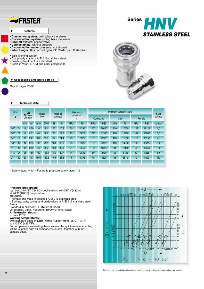
Features
�
• Connection system: pulling back the sleeve• Disconnection system: pulling back the sleeve• Shut-off system: poppet valve• Connectability: without pressure• Disconnection under pressure: not allowed• Interchangeability: according to ISO 7241-1 part B standard
• Balls latching system• Completely made of AISI 316 stainless steel• Polishing treatment is a standard• Seals in Viton, EPDM and other compounds
The descriptions and illustrations in this catalogue are for information only and are not binding.
SeriesHNVSTAINLESS STEEL

Female Male
19
Male Thread Ø AB
mm inc.C
mm inc.Ø D
mm inc.L
mm inc.CHF
mm inc.CHM
mm inc.Standards❖
HNV 14 GAS F2 HNV 14 GAS M2 1/4" BSP DIN 3852-2-X 56 2,20 35 1,38 28 1,1 70 2,76 19 0,75 19 0,75HNV 14 NPT F2 HNV 14 NPT M2 1/4" NPTF ANSI B 1.20.3 56 2,20 35 1,38 28 1,1 70 2,76 19 0,75 19 0,75
HNV 38 GAS F2 HNV 38 GAS M2 3/3" BSP DIN 3852-2-X 64 2,52 39 1,54 35 1,38 78 3,07 24 0,94 22 0,87HNV 38 NPT F2 HNV 38 NPT M2 3/8" NPTF ANSI B 1.20.3 64 2,52 39 1,54 35 1,38 78 3,07 24 0,94 22 0,87
HNV 12 GAS F2 HNV 12 GAS M2 1/2" BSP DIN 3852-2-X 71,5 2,81 44 1,73 44 1,73 88 3,46 30 1,18 27 1,06HNV 12 NPT F2 HNV 12 NPT M2 1/2" NPTF ANSI B 1.20.3 71,5 2,81 44 1,73 44 1,73 88 3,46 30 1,18 27 1,06
HNV 34 GAS F2 HNV 34 GAS M2 3/4" BSP DIN 3852-2-X 89 3,5 55 2,16 52 2,05 110 4,33 36 1,42 34 1,34HNV 34 NPT F2 HNV 34 NPT M2 3/4" NPTF ANSI B 1.20.3 89 3,5 55 2,16 52 2,05 110 4,33 36 1,42 34 1,34
HNV 1 GAS F2 HNV 1 GAS M2 1" BSP DIN 3852-2-X 106 4,17 66 2,6 62 2,44 132 5,19 41 1,61 41 1,61HNV 1 NPT F2 HNV 1 NPT M2 1" NPTF ANSI B 1.20.3 106 4,17 66 2,6 62 2,44 132 5,19 41 1,61 41 1,61
HNV 112-114 GAS F2 HNV 112-114 GAS M2 1 1/4" BSP DIN 3852-2-X 126 4,96 126 4,96 75 2,95 199 7,83 65 2,56 65 2,56HNV 112 GAS F2 HNV 112 GAS M2 1 1/2" BSP DIN 3852-2-X 126 4,96 126 4,96 75 2,95 199 7,83 65 2,56 65 2,56HNV 112-114 NPT F2 HNV 112-114 NPT M2 1 1/4" NPTF ANSI B 1.20.3 126 4,96 126 4,96 75 2,95 199 7,83 65 2,56 65 2,56HNV 112 NPT F2 HNV 112 NPT M2 1 1/2" NPTF ANSI B 1.20.3 126 4,96 126 4,96 75 2,95 199 7,83 65 2,56 65 2,56
HNV 2 GAS F2 HNV 2 GAS M2 2" BSP DIN 3852-2-X 142 5,59 142 5,59 105 4,13 220 8,66 90 3,54 90 3,54HNV 2 NPT F2 HNV 2 NPT M2 2" NPTF ANSI B 1.20.3 142 5,59 142 5,59 105 4,13 220 8,66 90 3,54 90 3,54HNV 2-212 NPT F2 HNV 2-212 NPT M2 2 1/2" NPTF ANSI B 1.20.3 164 6,46 164 6,46 105 4,13 264 10,4 90 3,54 90 3,54HNV 2-3 NPT F2 HNV 2-3 NPT M2 3" NPTF ANSI B 1.20.3 169 6,65 169 6,65 105 4,13 280 11 95 3,74 95 3,74
HNV 14-38SAE F2 HNV 14-38SAE M2 9/16" UNF SAE J1926-1 56 2,20 35 1,38 28 1,1 70 2,76 19 0,75 19 0,75
HNV 38-38S F2 HNV 38-38S M2 9/16" UNF SAE J1926-1 64 2,52 39 1,54 35 1,38 78 3,07 24 0,94 22 0,87
HNV 12-12S F2 HNV 12-12S M2 3/4" UNF SAE J1926-1 71,5 2,81 44 1,73 44 1,73 88 3,46 30 1,18 27 1,06HNV 12-58S F2 HNV 12-58S M2 7/8" UNF SAE J1926-1 71,5 2,81 44 1,73 44 1,73 88 3,46 30 1,18 27 1,06
HNV 34-34S F2 HNV 34-34S M2 1 1/16" UN SAE J1926-1 89 3,5 55 2,16 52 2,05 110 4,33 36 1,42 34 1,34
HNV 1-1SAE F2 HNV 1-1SAE M2 1 5/16" UN SAE J1926-1 106 4,17 66 2,6 62 2,44 132 5,19 41 1,61 41 1,61
HNV 112-114S F2 HNV 112-114S M2 1 5/8" UN SAE J1926-1 123 4,84 123 4,84 75 2,95 193 7,6 65 2,56 65 2,56HNV 112-112S F2 HNV 112-112S M2 1 7/8" UN SAE J1926-1 123 4,84 123 4,84 75 2,95 193 7,6 65 2,56 65 2,56
HNV 2-2SAE F2 HNV 2-2SAE M2 2 1/2" UN SAE J1926-1 142 5,59 142 5,59 105 4,13 220 8,66 90 3,54 90 3,54
* *
* *
* *
* *
* *
* *
* *
* *
* *
* *
ThreadedendThreaded end Female
04
06
08
12
16
24
32
A
A
A
A
A
A
A
B
B
B
B
B
B
B
❖
❖ Size GAS = BSP *On request
Available items
�
The descriptions and illustrations in this catalogue are for information only and are not binding.
A
B
SeriesHNVSTAINLESS STEEL

SeriesHNVBRASS
Pressure drop graph:test bench to ISO 7241-2 specifications with ISO VG 32 oilat 40°C (104°F) temperature.Materials:- Female, male, valves and guidevalves in brass
according to EN 12164 standards.- Springs and balls in AISI 316.Seals:Standard in oilproof NBR (Nitrile Rubber).On request: Viton, Neoprene, EPDM or other seals.Working temperatures:with standard seals in NBR (Nitrile Rubber) from -25°C (-13°F)to +125°C (+257°F).For temperature exceeding these values, the quick-release couplingwill be supplied with all components in steel together with thesuitable seals.
20
* Safety factor = 1:4 - For static pressure safety factor 1:2
SizeRatedflow
Fluidspillage
Force toconnect
Max. workpressure
Minimum burst pressure
Connected
1/8” 02
1/4” 04
3/8” 06
1/2” 08
3/4” 12
1” 16
1 1/2” 24
2” 32
l/min GPM N lb MPa PSI
Male Female
DNNominaldiameter
MPa PSIMPa PSI cc max.MPa PSI
2900
2538
2320
1450
2030
1015
870
130
100
110
102
80
40
31
18850
14500
15950
14790
11600
5800
4495
80
70
65
40
55
30
25
11600
10150
9425
5800
7975
4350
3625
100
110
65
50
58
33
27
14500
15950
9425
7250
8410
4785
3915
0,5
1,0
2,8
10
13
80
160
20
17
16
10
14
7
6
4.5
16
60
110
150
750
1600
1.2
4.2
15.9
29.1
39.7
198.4
423.3
24.2
16.5
21.4
39.6
39.6
40.7
35.2
110
75
97
180
180
185
160
*
Technical data
�
Accessories and spare part kit
See at pages 28-30.
�
mm inc.
4 0.16
5 0.20
2030 108 15660 55 7975 58 8410 1,51440 10.6 17.278
10 0.41
14 0.55
15 0.59
38 1.50
50 1.97
❖
Features
�
• Connection system: pulling back the sleeve• Disconnection system: pulling back the sleeve• Shut-off system: poppet valve• Connectability: without pressure• Disconnection under pressure: not allowed• Interchangeability: according to ISO 7241-1 part B standard
• Balls latching system• Completely made of brass according to EN 12164 standard• Seals in Viton, EPDM and other compounds
The descriptions and illustrations in this catalogue are for information only and are not binding.
8 0.31
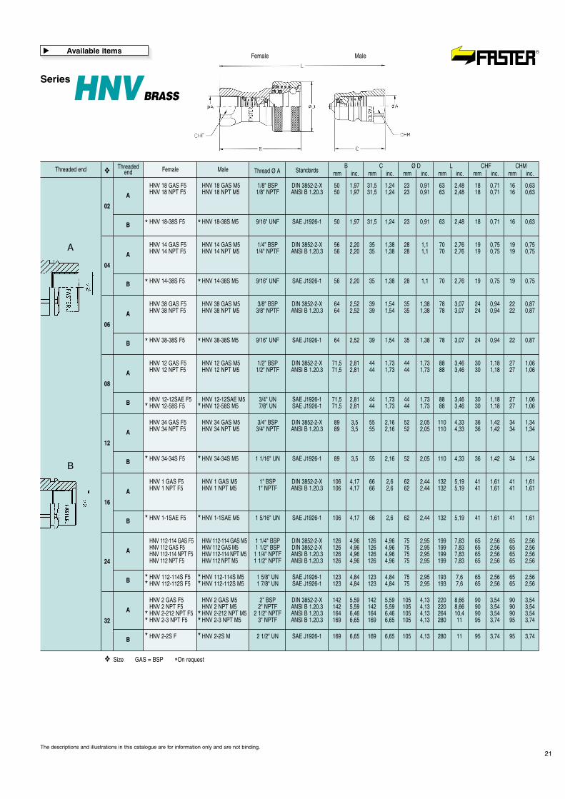
SeriesHNVBRASS
MaleFemale
21
Male Thread Ø AB
mm inc.C
mm inc.Ø D
mm inc.L
mm inc.CHF
mm inc.CHM
mm inc.Standards❖
HNV 18 GAS F5 HNV 18 GAS M5 1/8" BSP DIN 3852-2-X 50 1,97 31,5 1,24 23 0,91 63 2,48 18 0,71 16 0,63HNV 18 NPT F5 HNV 18 NPT M5 1/8" NPTF ANSI B 1.20.3 50 1,97 31,5 1,24 23 0,91 63 2,48 18 0,71 16 0,63
HNV 14 GAS F5 HNV 14 GAS M5 1/4" BSP DIN 3852-2-X 56 2,20 35 1,38 28 1,1 70 2,76 19 0,75 19 0,75HNV 14 NPT F5 HNV 14 NPT M5 1/4" NPTF ANSI B 1.20.3 56 2,20 35 1,38 28 1,1 70 2,76 19 0,75 19 0,75
HNV 38 GAS F5 HNV 38 GAS M5 3/8" BSP DIN 3852-2-X 64 2,52 39 1,54 35 1,38 78 3,07 24 0,94 22 0,87HNV 38 NPT F5 HNV 38 NPT M5 3/8" NPTF ANSI B 1.20.3 64 2,52 39 1,54 35 1,38 78 3,07 24 0,94 22 0,87
HNV 12 GAS F5 HNV 12 GAS M5 1/2" BSP DIN 3852-2-X 71,5 2,81 44 1,73 44 1,73 88 3,46 30 1,18 27 1,06HNV 12 NPT F5 HNV 12 NPT M5 1/2" NPTF ANSI B 1.20.3 71,5 2,81 44 1,73 44 1,73 88 3,46 30 1,18 27 1,06
HNV 34 GAS F5 HNV 34 GAS M5 3/4" BSP DIN 3852-2-X 89 3,5 55 2,16 52 2,05 110 4,33 36 1,42 34 1,34HNV 34 NPT F5 HNV 34 NPT M5 3/4" NPTF ANSI B 1.20.3 89 3,5 55 2,16 52 2,05 110 4,33 36 1,42 34 1,34
HNV 1 GAS F5 HNV 1 GAS M5 1" BSP DIN 3852-2-X 106 4,17 66 2,6 62 2,44 132 5,19 41 1,61 41 1,61HNV 1 NPT F5 HNV 1 NPT M5 1" NPTF ANSI B 1.20.3 106 4,17 66 2,6 62 2,44 132 5,19 41 1,61 41 1,61
HNV 112-114 GAS F5 HNV 112-114 GAS M5 1 1/4" BSP DIN 3852-2-X 126 4,96 126 4,96 75 2,95 199 7,83 65 2,56 65 2,56HNV 112 GAS F5 HNV 112 GAS M5 1 1/2" BSP DIN 3852-2-X 126 4,96 126 4,96 75 2,95 199 7,83 65 2,56 65 2,56HNV 112-114 NPT F5 HNV 112-114 NPT M5 1 1/4" NPTF ANSI B 1.20.3 126 4,96 126 4,96 75 2,95 199 7,83 65 2,56 65 2,56HNV 112 NPT F5 HNV 112 NPT M5 1 1/2" NPTF ANSI B 1.20.3 126 4,96 126 4,96 75 2,95 199 7,83 65 2,56 65 2,56
HNV 2 GAS F5 HNV 2 GAS M5 2" BSP DIN 3852-2-X 142 5,59 142 5,59 105 4,13 220 8,66 90 3,54 90 3,54HNV 2 NPT F5 HNV 2 NPT M5 2" NPTF ANSI B 1.20.3 142 5,59 142 5,59 105 4,13 220 8,66 90 3,54 90 3,54HNV 2-212 NPT F5 HNV 2-212 NPT M5 2 1/2" NPTF ANSI B 1.20.3 164 6,46 164 6,46 105 4,13 264 10,4 90 3,54 90 3,54HNV 2-3 NPT F5 HNV 2-3 NPT M5 3" NPTF ANSI B 1.20.3 169 6,65 169 6,65 105 4,13 280 11 95 3,74 95 3,74
HNV 18-38S F5 HNV 18-38S M5 9/16" UNF SAE J1926-1 50 1,97 31,5 1,24 23 0,91 63 2,48 18 0,71 16 0,63
HNV 14-38S F5 HNV 14-38S M5 9/16" UNF SAE J1926-1 56 2,20 35 1,38 28 1,1 70 2,76 19 0,75 19 0,75
HNV 38-38S F5 HNV 38-38S M5 9/16" UNF SAE J1926-1 64 2,52 39 1,54 35 1,38 78 3,07 24 0,94 22 0,87
HNV 12-12SAE F5 HNV 12-12SAE M5 3/4" UN SAE J1926-1 71,5 2,81 44 1,73 44 1,73 88 3,46 30 1,18 27 1,06HNV 12-58S F5 HNV 12-58S M5 7/8" UN SAE J1926-1 71,5 2,81 44 1,73 44 1,73 88 3,46 30 1,18 27 1,06
HNV 34-34S F5 HNV 34-34S M5 1 1/16" UN SAE J1926-1 89 3,5 55 2,16 52 2,05 110 4,33 36 1,42 34 1,34
HNV 1-1SAE F5 HNV 1-1SAE M5 1 5/16" UN SAE J1926-1 106 4,17 66 2,6 62 2,44 132 5,19 41 1,61 41 1,61
HNV 112-114S F5 HNV 112-114S M5 1 5/8" UN SAE J1926-1 123 4,84 123 4,84 75 2,95 193 7,6 65 2,56 65 2,56HNV 112-112S F5 HNV 112-112S M5 1 7/8" UN SAE J1926-1 123 4,84 123 4,84 75 2,95 193 7,6 65 2,56 65 2,56
HNV 2-2S F HNV 2-2S M 2 1/2" UN SAE J1926-1 169 6,65 169 6,65 105 4,13 280 11 95 3,74 95 3,74
*
*
*
*
*
*
* *
*
*
*
*
*
** *
* ** *
* *
ThreadedendThreaded end Female
02
04
06
08
12
16
24
32
A
A
A
A
A
A
A
A
B
B
B
B
B
B
B
B
❖
❖ Size GAS = BSP *On request
Available items
�
The descriptions and illustrations in this catalogue are for information only and are not binding.
A
B
SeriesTNV
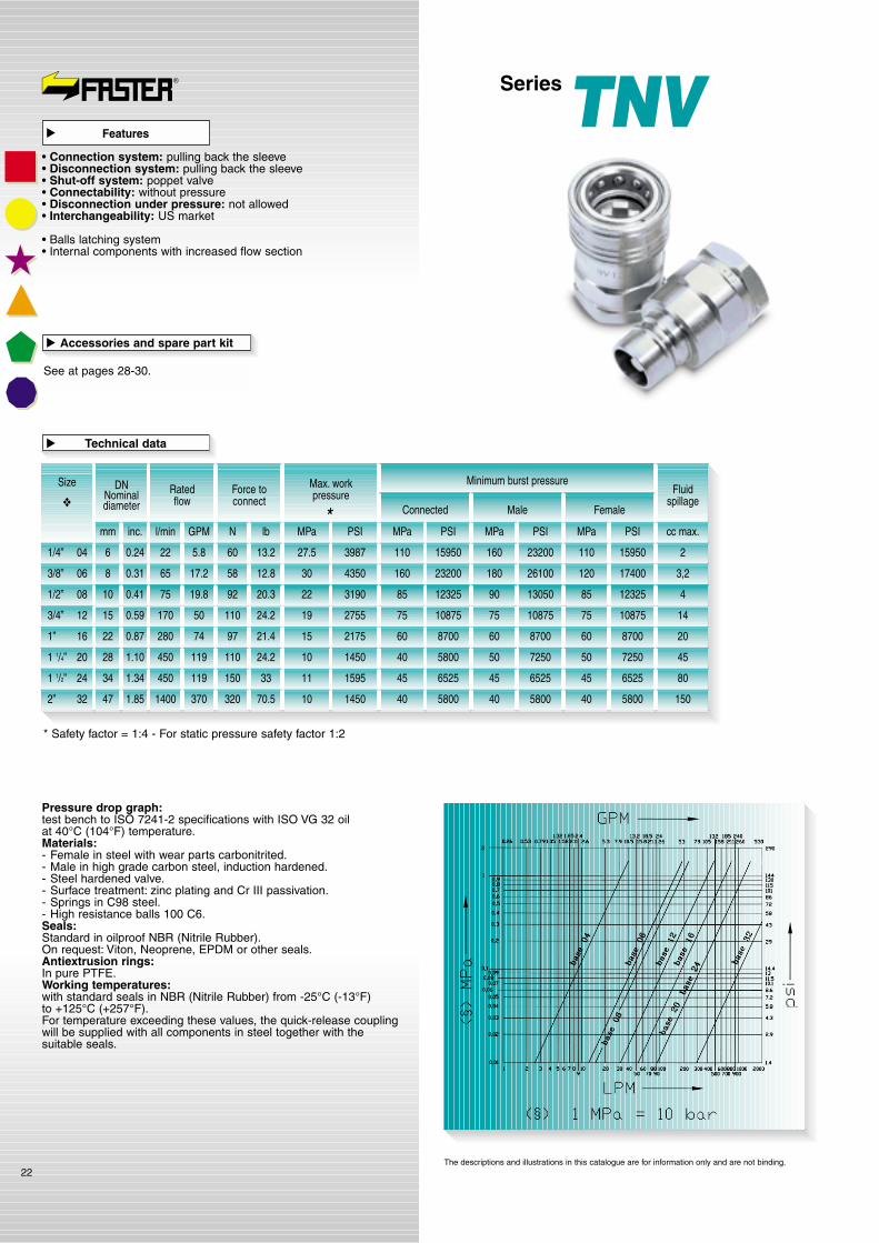
Pressure drop graph:test bench to ISO 7241-2 specifications with ISO VG 32 oilat 40°C (104°F) temperature.Materials:- Female in steel with wear parts carbonitrited.- Male in high grade carbon steel, induction hardened.- Steel hardened valve.- Surface treatment: zinc plating and Cr III passivation.- Springs in C98 steel.- High resistance balls 100 C6.Seals:Standard in oilproof NBR (Nitrile Rubber).On request: Viton, Neoprene, EPDM or other seals.Antiextrusion rings:In pure PTFE.Working temperatures:with standard seals in NBR (Nitrile Rubber) from -25°C (-13°F)to +125°C (+257°F).For temperature exceeding these values, the quick-release couplingwill be supplied with all components in steel together with thesuitable seals.
22
* Safety factor = 1:4 - For static pressure safety factor 1:2
Size Ratedflow
Fluidspillage
Force toconnect
Max. workpressure
Minimum burst pressure
Connected
1/4” 04
3/8” 06
1/2” 08
3/4” 12
1” 16
1 1/4” 20
1 1/2” 24
2” 32
l/min GPM N lb MPa PSI
Male Female
DNNominaldiameter
MPa PSIMPa PSI cc max.MPa PSI
3987
4350
2755
2175
1450
1595
1450
110
160
75
60
40
45
40
15950
23200
10875
8700
5800
6525
5800
160
180
75
60
50
45
40
23200
26100
10875
8700
7250
6525
5800
110
120
75
60
50
45
40
15950
17400
10875
8700
7250
6525
5800
2
3,2
14
20
45
80
150
27.5
30
19
15
10
11
10
22
65
170
280
450
450
1400
5.8
17.2
50
74
119
119
370
13.2
12.8
24.2
21.4
24.2
33
70.5
60
58
110
97
110
150
320
*
Technical data
�
Accessories and spare part kit
See at pages 28-30.
�
mm inc.
6 0.24
8 0.31
3190 85 12325 90 13050 85 12325 42275 19.8 20.392
15 0.59
22 0.87
28 1.10
34 1.34
47 1.85
❖
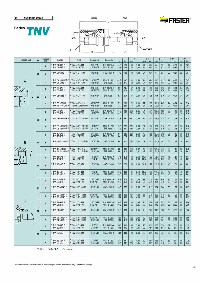
Features
�
• Connection system: pulling back the sleeve• Disconnection system: pulling back the sleeve• Shut-off system: poppet valve• Connectability: without pressure• Disconnection under pressure: not allowed• Interchangeability: US market
• Balls latching system• Internal components with increased flow section
The descriptions and illustrations in this catalogue are for information only and are not binding.
10 0.41
SeriesTNV
23
Male Thread Ø AB
mm inc.C
mm inc.Ø D
mm inc.L
mm inc.CHF
mm inc.CHM
mm inc.Standards❖
TNV 04 GAS F TNV 04 GAS M 1/4" BSP DIN 3852-2-X 49,8 1,96 49 1,93 24 0,94 84 3,31 22 0,87 22 0,87TNV 04 NPT F TNV 04 NPT M 1/4" NPTF ANSI B 1.20.3 49,8 1,96 49 1,93 24 0,94 84 3,31 22 0,87 22 0,87
TNV 06 GAS F TNV 06 GAS M 3/8" BSP DIN 3852-2-X 57 2,24 57 2,24 27 1,06 95,6 3,76 24 0,94 24 0,94TNV 06 NPT F TNV 06 NPT M 3/8" NPTF ANSI B 1.20.3 57 2,24 57 2,24 27 1,06 95,6 3,76 24 0,94 24 0,94
TNV 08 GAS F TNV 08 GAS M 1/2" BSP DIN 3852-2-X 64,3 2,53 62,3 2,45 34 1,34 108,6 4,28 30 1,18 30 1,18TNV 08 NPT F TNV 08 NPT M 1/2" NPTF ANSI B 1.20.3 64,3 2,53 62,3 2,45 34 1,34 108,6 4,28 30 1,18 30 1,18
TNV 12 GAS F TNV 12 GAS M 3/4" BSP DIN 3852-2-X 64 2,52 63,5 2,50 42 1,65 127,5 5,02 36 1,42 36 1,42TNV 12 NPT F TNV 12 NPT M 3/4" NPTF ANSI B 1.20.3 64 2,52 63,5 2,50 42 1,65 127,5 5,02 36 1,42 36 1,42
TNV 16 GAS F TNV 16 GAS M 1" BSP DIN 3852-2-X 70,5 2,78 68 2,68 50,5 1,99 115,5 4,55 46 1,81 46 1,81TNV 16 NPT F TNV 16 NPT M 1" NPTF ANSI B 1.20.3 70,5 2,78 68 2,68 50,5 1,99 115,5 4,55 46 1,81 46 1,81
TNV 20 GAS F TNV 20 GAS M 1 1/4" BSP DIN 3852-2-X 96,3 3,79 91 3,58 56 2,2 164 6,46 50 1,97 50 1,97TNV 20 NPT F TNV 20 NPT M 1 1/4" NPTF ANSI B 1.20.3 96,3 3,79 91 3,58 56 2,2 164 6,46 50 1,97 50 1,97
TNV 24 GAS F TNV 24 GAS M 1 1/2" BSP DIN 3852-2-X 90,5 3,56 85 3,35 70 2,76 148 5,83 65 2,56 65 2,56TNV 24 NPT F TNV 24 NPT M 1 1/2" NPTF ANSI B 1.20.3 90,5 3,56 85 3,35 70 2,76 148 5,83 65 2,56 65 2,56
TNV 32 GAS F TNV 32 GAS M 2" BSP DIN 3852-2-X 102 4,02 98 3,86 90 3,54 166 6,54 89 3,5 89 3,5TNV 32 NPT F TNV 32 NPT M 2" NPTF ANSI B 1.20.3 102 4,02 98 3,86 90 3,54 166 6,54 89 3,5 89 3,5
TNV 04 0/14S F TNV 04 0/14S M 7/16" UNF SAE J1926-1 49,8 1,96 49 1,93 24 0,94 84 3,31 22 0,87 22 0,87
TNV 06 0/38S F TNV 06 0/38S M 9/16" UNF SAE 1926-1 57 2,24 57 2,24 27 1,06 95,6 3,76 24 0,94 24 0,94
TNV 08 0/34 UNF F TNV 08 0/34 UNF M 3/4" UNF SAE J1926-1 64,3 2,53 62,3 2,45 34 1,34 108,6 4,28 30 1,18 30 1,18
TNV 12 0/1116UN F TNV 12 0/1116UN M 1 1/16" UN SAE J1926-1 64 2,52 63,5 2,50 42 1,65 127,5 5,02 36 1,42 36 1,42
TNV 16 0/1S F TNV 16 0/1S M 1 5/16" UN SAE J1926-1 70,5 2,78 68 2,68 50,5 1,99 115,5 4,55 46 1,81 46 1,81
TNV 20 0/114S F TNV 20 0/114S M 1 5/8" UN SAE J1926-1 96,3 3,79 91 3,58 56 2,2 164 6,46 50 1,97 36 1,97
TNV 24 0/112S F TNV 24 0/112S M 1 7/8" UN SAE J1926-1 90,5 3,56 85 3,35 70 2,76 148 5,83 65 2,56 65 2,56
TNV 32 0/2S F TNV 32 0/2S M 2 1/2" UN SAE J1926-1 102 4,02 98 3,86 90 3,54 166 6,54 89 3,5 89 3,5
TNV 04 1/14 NPT F TNV 04 1/14 NPT M 1/4" NPTF ANSI B 1.20.3 62,8 2,47 62 2,44 24 0,94 110 4,33 22 0,87 22 0,87TNV 04 1/14S F TNV 04 1/14S M 7/16" UNF SAE 1926-3 62,8 2,47 62 2,44 24 0,94 110 4,33 22 0,87 22 0,87
TNV 06 1/38 N F TNV 06 1/38 N M 3/8" NPTF ANSI B 1.20.3 71 2,80 71 2,80 27 1,06 123,6 4,87 24 0,94 24 0,94TNV 06 1/916 UNF F TNV 06 1/916 UNF M 9/16" UNF SAE 1926-3 71 2,80 71 2,80 27 1,06 123,6 4,87 24 0,94 24 0,94
TNV 08 1/12 NPT F TNV 08 1/12 NPT M 1/2" NPTF ANSI B 1.20.3 75,5 2,97 73,5 2,89 34 1,34 131 5,16 30 1,18 30 1,18TNV 08 1/34 UNF F TNV 08 1/34 UNF M 3/4" UNF SAE 1926-3 75,5 2,97 73,5 2,89 34 1,34 131 5,16 30 1,18 30 1,18
TNV 12 1/34 N F TNV 12 1/34 N M 3/4" NPTF ANSI B 1.20.3 86 3,39 85,5 3,37 42 1,65 171,5 6,75 36 1,42 36 1,42TNV 12 1/1116UN F TNV 12 1/1116UN M 1 1/16" UN SAE 1926-3 86 3,39 85,5 3,37 42 1,65 171,5 6,75 36 1,42 36 1,42
TNV 16 1/1N F TNV 16 1/1N M 1" NPTF ANSI B 1.20.3 83,5 3,29 81 3,19 50,5 1,99 141,5 5,57 46 1,81 46 1,81TNV 16 1/1S F TNV 16 1/1S M 1 5/16" UN SAE 1926-3 83,5 3,29 81 3,19 50,5 1,99 141,5 5,57 46 1,81 46 1,81
TNV 20 1/114N F TNV 20 1/114N M 1 1/4" NPTF ANSI B 1.20.3 109 4,29 104 4,09 56 2,2 190 7,48 50 1,97 50 1,97TNV 20 1/114S F TNV 20 1/114S M 1 5/8" UN SAE 1926-3 109 4,29 104 4,09 56 2,2 190 7,48 50 1,97 50 1,97
TNV 24 1/112N F TNV 24 1/112N M 1 1/2" NPTF ANSI B 1.20.3 106 4,17 100 3,94 70 2,76 178 7,01 65 2,56 65 2,56TNV 24 1/112S F TNV 24 1/112S M 1 7/8" UN SAE 1926-3 106 4,17 100 3,94 70 2,76 178 7,01 65 2,56 65 2,56
TNV 32 1/2N F TNV 32 1/2N M 2" NPTF ANSI B 1.20.3 117 4,61 113 4,45 90 3,54 196 7,72 89 3,5 89 3,5TNV 32 1/2S F TNV 32 1/2S M 2 1/2" UN SAE 1926-3 117 4,61 113 4,45 90 3,54 196 7,72 89 3,5 89 3,5
* *
* *
* *
* *
* *
* *
* *
* *
* *
* *
* *
* *
* *
* *
* *
* *
* *
* *
* *
* *
* *
* *
*
ThreadedendThreaded end Female
04
06
08
12
16
20
24
32
A
A
A
A
A
A
A
A
B
B
B
B
B
B
B
B
C
C
C
C
C
C
C
C
❖
❖ Size GAS = BSP *On request
Available items
�
The descriptions and illustrations in this catalogue are for information only and are not binding.
A
B
C
MaleFemale
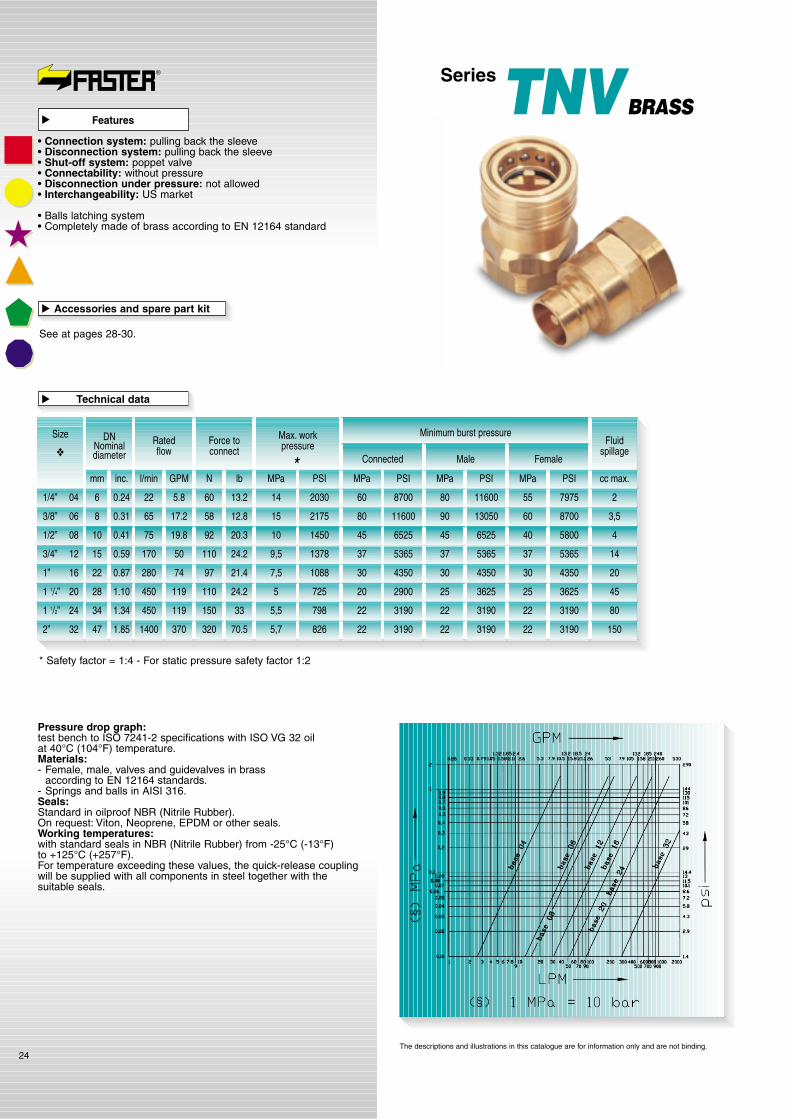
SeriesTNVBRASS
Pressure drop graph:test bench to ISO 7241-2 specifications with ISO VG 32 oilat 40°C (104°F) temperature.Materials:- Female, male, valves and guidevalves in brass
according to EN 12164 standards.- Springs and balls in AISI 316.Seals:Standard in oilproof NBR (Nitrile Rubber).On request: Viton, Neoprene, EPDM or other seals.Working temperatures:with standard seals in NBR (Nitrile Rubber) from -25°C (-13°F)to +125°C (+257°F).For temperature exceeding these values, the quick-release couplingwill be supplied with all components in steel together with thesuitable seals.
24
* Safety factor = 1:4 - For static pressure safety factor 1:2
SizeRatedflow
Fluidspillage
Force toconnect
Max. workpressure
Minimum burst pressure
Connected
1/4” 04
3/8” 06
1/2” 08
3/4” 12
1” 16
1 1/4” 20
1 1/2” 24
2” 32
l/min GPM N lb MPa PSI
Male Female
DNNominaldiameter
MPa PSIMPa PSI cc max.MPa PSI
2030
2175
1378
1088
725
798
826
60
80
37
30
20
22
22
8700
11600
5365
4350
2900
3190
3190
80
90
37
30
25
22
22
11600
13050
5365
4350
3625
3190
3190
55
60
37
30
25
22
22
7975
8700
5365
4350
3625
3190
3190
2
3,5
14
20
45
80
150
14
15
9,5
7,5
5
5,5
5,7
22
65
170
280
450
450
1400
5.8
17.2
50
74
119
119
370
13.2
12.8
24.2
21.4
24.2
33
70.5
60
58
110
97
110
150
320
*
Technical data
�
Accessories and spare part kit
See at pages 28-30.
�
mm inc.
6 0.24
8 0.31
1450 45 6525 45 6525 40 5800 41075 19.8 20.392
15 0.59
22 0.87
28 1.10
34 1.34
47 1.85
❖
Features
�
• Connection system: pulling back the sleeve• Disconnection system: pulling back the sleeve• Shut-off system: poppet valve• Connectability: without pressure• Disconnection under pressure: not allowed• Interchangeability: US market
• Balls latching system• Completely made of brass according to EN 12164 standard
The descriptions and illustrations in this catalogue are for information only and are not binding.
10 0.41

MaleFemale
SeriesTNVBRASS
25
Male Thread Ø AB
mm inc.C
mm inc.Ø D
mm inc.L
mm inc.CHF
mm inc.CHM
mm inc.Standards❖
TNV 04 GAS F5 TNV 04 GAS M5 1/4" BSP DIN 3852-2-X 49,8 1,96 49 1,93 24 0,94 84 3,31 22 0,87 22 0,87TNV 04 NPT F5 TNV 04 NPT M5 1/4" NPTF ANSI B 1.20.3 49,8 1,96 49 1,93 24 0,94 84 3,31 22 0,87 22 0,87
TNV 06 GAS F5 TNV 06 GAS M5 3/8" BSP DIN 3852-2-X 57 2,24 57 2,24 27 1,06 95,6 3,76 24 0,94 24 0,94TNV 04 NPT F5 TNV 04 NPT M5 3/8" NPTF ANSI B 1.20.3 57 2,24 57 2,24 27 1,06 95,6 3,76 24 0,94 24 0,94
TNV 08 GAS F5 TNV 08 GAS M5 1/2" BSP DIN 3852-2-X 64,3 2,53 62,3 2,45 34 1,34 108,6 4,28 30 1,18 30 1,18TNV 08 NPT F5 TNV 08 NPT M5 1/2" NPTF ANSI B 1.20.3 64,3 2,53 62,3 2,45 34 1,34 108,6 4,28 30 1,18 30 1,18
TNV 12 GAS F5 TNV 12 GAS M5 3/4" BSP DIN 3852-2-X 64 2,52 63,5 2,50 42 1,65 127,5 5,02 36 1,42 36 1,42TNV 12 NPT F5 TNV 12 NPT M5 3/4" NPTF ANSI B 1.20.3 64 2,52 63,5 2,50 42 1,65 127,5 5,02 36 1,42 36 1,42
TNV 16 GAS F5 TNV 16 GAS M5 1" BSP DIN 3852-2-X 70,5 2,78 68 2,68 50,5 1,99 115,5 4,55 48 1,89 48 1,89TNV 16 NPT F5 TNV 16 NPT M5 1" NPTF ANSI B 1.20.3 70,5 2,78 68 2,68 50,5 1,99 115,5 4,55 48 1,89 48 1,89
TNV 20 GAS F5 TNV 20 GAS M5 1 1/4" BSP DIN 3852-2-X 96,3 3,79 91 3,58 56 2,2 164 6,46 50 1,97 50 1,97TNV 20 NPT F5 TNV 20 NPT M5 1 1/4" NPTF ANSI B 1.20.3 96,3 3,79 91 3,58 56 2,2 164 6,46 50 1,97 50 1,97
TNV 24 GAS F5 TNV 24 GAS M5 1 1/2" BSP DIN 3852-2-X 90,5 3,56 85 3,35 70 2,76 148 5,83 65 2,56 65 2,56TNV 24 NPT F5 TNV 24 NPT M5 1 1/2" NPTF ANSI B 1.20.3 90,5 3,56 85 3,35 70 2,76 148 5,83 65 2,56 65 2,56
TNV 32 GAS F5 TNV 32 GAS M5 2" BSP DIN 3852-2-X 102 4,02 98 3,86 90 3,54 166 6,54 89 3,5 89 3,5TNV 32 NPT F5 TNV 32 NPT M5 2" NPTF ANSI B 1.20.3 102 4,02 98 3,86 90 3,54 166 6,54 89 3,5 89 3,5
TNV 04 0/14S F5 TNV 04 0/14S M5 7/16" UNF SAE J1926-1 49,8 1,96 49 1,93 24 0,94 84 3,31 22 0,87 22 0,87
TNV 04 0/38S F5 TNV 04 0/38S M5 9/16" UNF SAE J1926-1 57 2,24 57 2,24 27 1,06 87,7 3,45 24 0,94 24 0,94
TNV 08 0/12S F5 TNV 08 0/12S M5 3/4" UNF SAE J1926-1 64,3 2,53 62,3 2,45 34 1,34 108,6 4,28 30 1,18 30 1,18
TNV 12 0/34S F5 TNV 12 0/34S M5 1 1/16" UN SAE J1926-1 64 2,52 63,5 2,50 42 1,65 127,5 5,02 36 1,42 36 1,42
TNV 16 0/1S F5 TNV 16 0/1S M5 1 5/16" UN SAE J1926-1 70,5 2,78 68 2,68 50,5 1,99 115,5 4,55 48 1,89 48 1,89
TNV 20 0/114S F5 TNV 20 0/114S M5 1 5/8" UN SAE J1926-1 96,3 3,79 91 3,58 56 2,2 164 6,46 50 1,97 50 1,97
TNV 24 0/112S F5 TNV 24 0/112S M5 1 7/8" UN SAE J1926-1 90,5 3,56 85 3,35 70 2,76 148 5,83 65 2,56 65 2,56
TNV 32 0/25S F5 TNV 32 0/25S M5 2 1/2" UN SAE J1926-1 102 4,02 98 3,86 90 3,54 166 6,54 89 3,5 89 3,5
TNV 04 1/14N F5 TNV 04 1/14N M5 1/4" NPTF ANSI B 1.20.3 62,8 2,47 62 2,44 24 0,94 110 4,33 22 0,87 22 0,87TNV 04 1/14S F5 TNV 04 1/14S M5 7/16" UNF SAE 1926-3 62,8 2,47 62 2,44 24 0,94 110 4,33 22 0,87 22 0,87
TNV 06 1/38N F5 TNV 06 1/38N M5 3/8" NPTF ANSI B 1.20.3 71 2,80 71 2,80 27 1,06 123,6 4,87 24 0,94 24 0,94TNV 06 1/38S F5 TNV 06 1/38S M5 9/16" UNF SAE 1926-3 71 2,80 71 2,80 27 1,06 123,6 4,87 24 0,94 24 0,94
TNV 08 1/12N F5 TNV 08 1/12N M5 1/2" NPTF ANSI B 1.20.3 75,5 2,97 73,5 2,89 34 1,34 131 5,16 30 1,18 30 1,18TNV 08 1/12S F5 TNV 08 1/12S M5 3/4" UNF SAE 1926-3 75,5 2,97 73,5 2,89 34 1,34 131 5,16 30 1,18 30 1,18
TNV 12 1/34N F5 TNV 12 1/34N M5 3/4" NPTF ANSI B 1.20.3 86 3,39 85,5 3,37 42 1,65 171,5 6,75 36 1,42 36 1,42TNV 12 1/34S F5 TNV 12 1/34S M5 1 1/16" UN SAE 1926-3 86 3,39 85,5 3,37 42 1,65 171,5 6,75 36 1,42 36 1,42
TNV 16 1/1N F5 TNV 16 1/1N M5 1" NPTF ANSI B 1.20.3 83,5 3,29 81 3,19 50,5 1,99 141,5 5,57 48 1,89 48 1,89TNV 16 1/1S F5 TNV 16 1/1S M5 1 5/16" UN SAE 1926-3 83,5 3,29 81 3,19 50,5 1,99 141,5 5,57 48 1,89 48 1,89
TNV 20 1/114N F5 TNV 20 1/114N M5 1 1/4" NPTF ANSI B 1.20.3 109 4,29 104 4,09 56 2,2 190 7,48 50 1,97 50 1,97TNV 20 1/114S F5 TNV 20 1/114S M5 1 5/8" UN SAE 1926-3 109 4,29 104 4,09 56 2,2 190 7,48 50 1,97 50 1,97
TNV 24 1/112N F5 TNV 24 1/112N M5 1 1/2" NPTF ANSI B 1.20.3 106 4,17 100 3,94 70 2,76 178 7,01 65 2,56 65 2,56TNV 24 1/112S F5 TNV 24 1/112S M5 1 7/8" UN SAE 1926-3 106 4,17 100 3,94 70 2,76 178 7,01 65 2,56 65 2,56
TNV 32 1/2N F5 TNV 32 1/2N M5 2" NPTF ANSI B 1.20.3 117 4,61 113 4,45 90 3,54 196 7,72 89 3,5 89 3,5TNV 32 1/2S F5 TNV 32 1/2S M5 2 1/2" UN SAE 1926-3 117 4,61 113 4,45 90 3,54 196 7,72 89 3,5 89 3,5
* ** *
* *
* ** *
* ** *
* *
* ** *
* *
* *
* ** *
* *
* *
* ** *
* *
* ** *
* *
* *
* ** *
* *
* ** *
* *
* ** *
* ** *
ThreadedendThreaded end Female
04
06
08
12
16
20
24
32
A
A
A
A
A
A
A
A
B
B
B
B
B
B
B
B
C
C
C
C
C
C
C
C
❖
❖ Size GAS = BSP *On request
Available items
�
The descriptions and illustrations in this catalogue are for information only and are not binding.
A
B
C
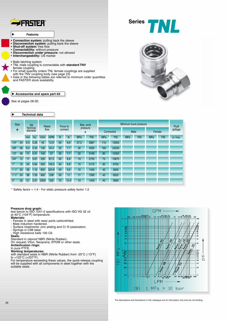
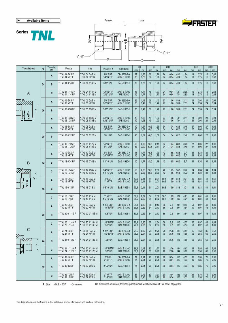
SeriesTNL
Pressure drop graph:test bench to ISO 7241-2 specifications with ISO VG 32 oilat 40°C (104°F) temperature.Materials:- Female in steel with wear parts carbonitrited.- Male induction hardened.- Surface treatments: zinc plating and Cr III passivation.- Springs in C98 steel.- High resistance balls 100 C6.Seals:Standard in oilproof NBR (Nitrile Rubber).On request: Viton, Neoprene, EPDM or other seals.Antiextrusion rings:In pure PTFE.Working temperatures:with standard seals in NBR (Nitrile Rubber) from -25°C (-13°F)to +125°C (+257°F).For temperature exceeding these values, the quick-release couplingwill be supplied with all components in steel together with thesuitable seals.
26
* Safety factor = 1:4 - For static pressure safety factor 1:2
SizeRatedflow
Fluidspillage
Force toconnect
Max. workpressure
Minimum burst pressure
Connected
1/4” 04
3/8” 06
1/2” 08
3/4” 12
1” 16
1 1/4” 20
1 1/2” 24
2” 32
l/min GPM N lb MPa PSI
Male Female
DNNominaldiameter
MPa PSIMPa PSI cc max.MPa PSI
3987
4350
2755
2175
1450
1595
1450
110
160
75
60
40
45
40
15950
23200
10875
8700
5800
6525
5800
27,5
30
19
15
10
11
10
45
130
330
550
850
900
2000
12,9
34.4
87.3
145.5
224.9
238
529
6.6
7.7
8.8
8.8
9.9
11
15.4
30
35
40
40
45
50
70
*
Technical data
�
Accessories and spare part kit
See at pages 28-30.
�
mm inc.
6.5 0.26
8.5 0.33
3190 85 1232522140 37 7.735
17 0.67
24 0.94
28 1.10
38 1.50
51 2.01
❖
Features
�
• Connection system: pulling back the sleeve• Disconnection system: pulling back the sleeve• Shut-off system: free flow• Connectability: without pressure• Disconnection under pressure: not allowed• Interchangeability: US market
• Balls latching system• TNL male coupling is connectable with standard TNV
female coupling• For small quantity orders TNL female couplings are supplied
with the TNV coupling body (see page 23)• Data in the following tables are referred to minimum order quantities
and FASTER stock availability
The descriptions and illustrations in this catalogue are for information only and are not binding.
11 0.41
SeriesTNL
27
Male Thread Ø AB#
mm inc.C
mm inc.Ø D
mm inc.L
mm inc.CHF
mm inc.CHM
mm inc.Standards❖
TNL 04 GAS F TNL 04 GAS M 1/4" BSP DIN 3852-2-X 32 1,26 32 1,26 24 0,94 49,2 1,94 19 0,75 16 0,63TNL 04 NPT F TNL 04 NPT M 1/4" NPTF ANSI B 1.20.3 32 1,26 32 1,26 24 0,94 49,2 1,94 19 0,75 16 0,63
TNL 06 GAS F TNL 06 GAS M 3/8" BSP DIN 3852-2-X 36 1,42 36 1,42 27 1,06 53,6 2,11 24 0,94 24 0,94TNL 06 NPT F TNL 06 NPT M 3/8" NPTF ANSI B 1.20.3 36 1,42 36 1,42 27 1,06 53,6 2,11 24 0,94 24 0,94
TNL 08 GAS F TNL 08 GAS M 1/2" BSP DIN 3852-2-X 40 1,57 40,5 1,59 34 1,34 62,5 2,46 27 1,06 27 1,06TNL 08 NPT F TNL 08 NPT M 1/2" NPTF ANSI B 1.20.3 40 1,57 40,5 1,59 34 1,34 62,5 2,46 27 1,06 27 1,06
TNL 12 GAS F TNL 12 GAS M 3/4" BSP DIN 3852-2-X 45 1,77 45,5 1,79 42 1,65 68,5 2,7 34 1,34 34 1,34TNL 12 NPT F TNL 12 NPT M 3/4" NPTF ANSI B 1.20.3 45 1,77 45,5 1,79 42 1,65 68,5 2,7 34 1,34 34 1,34
TNL 16 GAS F TNL 16 GAS M 1" BSP DIN 3852-2-X 53,5 2,11 51 2,01 50,5 1,99 81,5 3,21 46 1,81 41 1,61TNL 16 NPT F TNL 16 NPT M 1" NPTF ANSI B 1.20.3 53,5 2,11 51 2,01 50,5 1,99 81,5 3,21 46 1,81 41 1,61
TNL 20 GAS F TNL 20 GAS M 1 1/4" BSP DIN 3852-2-X 59,3 2,33 54 2,13 56 2,2 90 3,54 50 1,97 48 1,89TNL 20 NPT F TNL 20 NPT M 1 1/4" NPTF ANSI B 1.20.3 59,3 2,33 54 2,13 56 2,2 90 3,54 50 1,97 48 1,89
TNL 24 GAS F TNL 24 GAS M 1 1/2" BSP DIN 3852-2-X 75,5 2,97 70 2,76 70 2,76 118 4,65 65 2,56 65 2,56TNL 24 NPT F TNL 24 NPT M 1 1/2" NPTF ANSI B 1.20.3 75,5 2,97 70 2,76 70 2,76 118 4,65 65 2,56 65 2,56
TNL 32 GAS F TNL 32 GAS M 2" BSP DIN 3852-2-X 74 2,91 70 2,76 90 3,54 110 4,33 85 3,35 75 2,95TNL 32 NPT F TNL 32 NPT M 2" NPTF ANSI B 1.20.3 74 2,91 70 2,76 90 3,54 110 4,33 85 3,35 75 2,95
TNL 04 0/14S F TNL 04 0/14S M 7/16" UNF SAE J1926-1 32 1,26 32 1,26 24 0,94 49,2 1,94 19 0,75 16 0,63
TNL 06 0/38S F TNL 06 0/38S M 9/16" UNF SAE J1926-1 36 1,42 36 1,42 27 1,06 53,6 2,11 24 0,94 24 0,94
TNL 08 0/12S F TNL 08 0/12S M 3/4" UNF SAE J1926-1 40 1,57 40,5 1,59 34 1,34 62,5 2,46 27 1,06 27 1,06
TNL 12 0/34S F TNL 12 0/34S M 1 1/16" UN SAE J1926-1 45 1,77 45,5 1,79 42 1,65 68,5 2,7 34 1,34 34 1,34
TNL 16 0/1S F TNL 16 0/1S M 1 5/16" UN SAE J1926-1 53,5 2,11 51 2,01 50,5 1,99 81,5 3,21 46 1,81 41 1,61
TNL 20 0/114S F TNL 20 0/114S M 1 5/8" UN SAE J1926-1 59,3 2,33 54 2,13 56 2,2 90 3,54 50 1,97 48 1,89
TNL 24 0/112S F TNL 24 0/112S M 1 7/8" UN SAE J1926-1 75,5 2,97 70 2,76 70 2,76 118 4,65 65 2,56 65 2,56
TNL 32 0/2S F TNL 32 0/2S M 2 1/2" UN SAE J1926-1 74 2,91 70 2,76 90 3,54 110 4,33 85 3,35 75 2,95
TNL 04 1/14N F TNL 04 1/14N M 1/4" NPTF ANSI B 1.20.3 45 1,77 45 1,77 24 0,94 75 2,95 19 0,75 16 0,63TNL 04 1/14S F TNL 04 1/14S M 7/16" UNF SAE 1926-3 45 1,77 45 1,77 24 0,94 75 2,95 19 0,75 16 0,63
TNL 06 1/38N F TNL 06 1/38N M 3/8" NPTF ANSI B 1.20.3 49 1,93 49 1,93 27 1,06 79 3,11 24 0,94 24 0,94TNL 06 1/38S F TNL 06 1/38S M 9/16" UNF SAE 1926-3 49 1,93 49 1,93 27 1,06 79 3,11 24 0,94 24 0,94
TNL 08 1/12N F TNL 08 1/12N M 1/2" NPTF ANSI B 1.20.3 53 2,09 53,5 2,11 34 1,34 88,5 3,48 27 1,06 27 1,06TNL 08 1/12S F TNL 08 1/12S M 3/4" UNF SAE 1926-3 53 2,09 53,5 2,11 34 1,34 88,5 3,48 27 1,06 27 1,06
TNL 12 1/34N F TNL 12 1/34N M 3/4" NPTF ANSI B 1.20.3 58 2,28 58,5 2,30 42 1,65 94,5 3,72 34 1,34 34 1,34TNL 12 1/34S F TNL 12 1/34S M 1 1/16" UN SAE 1926-3 58 2,28 58,5 2,30 42 1,65 94,5 3,72 34 1,34 34 1,34
TNL 16 1/1N F TNL 16 1/1N M 1" NPTF ANSI B 1.20.3 66,5 2,62 64 2,52 50,5 1,99 107 4,21 46 1,81 41 1,61TNL 16 1/1S F TNL 16 1/1S M 1 5/16" UN SAE 1926-3 66,5 2,62 64 2,52 50,5 1,99 107 4,21 46 1,81 41 1,61
TNL 20 1/114N F TNL 20 1/114N M 1 1/4" NPTF ANSI B 1.20.3 72,3 2,85 67 2,64 56 2,2 116 4,57 50 1,97 48 1,89TNL 20 1/114S F TNL 20 1/114S M 1 5/8" UN SAE 1926-3 72,3 2,85 67 2,64 56 2,2 116 4,57 50 1,97 48 1,89
TNL 24 1/112N F TNL 20 1/112N M 1 1/2" NPTF ANSI B 1.20.3 88,5 3,48 83 3,27 70 2,76 144 5,67 65 2,56 65 2,56TNL 24 1/112S F TNL 20 1/112S M 1 7/8" UN SAE 1926-3 88,5 3,48 83 3,27 70 2,76 144 5,67 65 2,56 65 2,56
TNL 32 1/2N F TNL 32 1/2N M 2" NPTF ANSI B 1.20.3 87 3,43 83 3,27 90 3,54 136 5,35 85 3,35 75 2,95TNL 32 1/2S F TNL 32 1/2S M 2 1/2" UN SAE 1926-3 87 3,43 83 3,27 90 3,54 136 5,35 85 3,35 75 2,95
* *
* *
* ** *
* *
* *
* ** *
* *
* ** *
* *
* *
* ** *
* *
* *
* ** *
* *
* *
* ** *
* *
* *
* ** *
* *
* *
* ** *
ThreadedendThreaded end Female
04
06
08
12
16
20
24
32
A
A
A
A
A
A
A
A
B
B
B
B
B
B
B
B
C
C
C
C
C
C
C
C
❖
❖ Size GAS = BSP *On request B#: dimensions on request, for small quantity orders see B dimension of TNV series at page 23
Available items
�
The descriptions and illustrations in this catalogue are for information only and are not binding.
A
B
C
MaleFemale
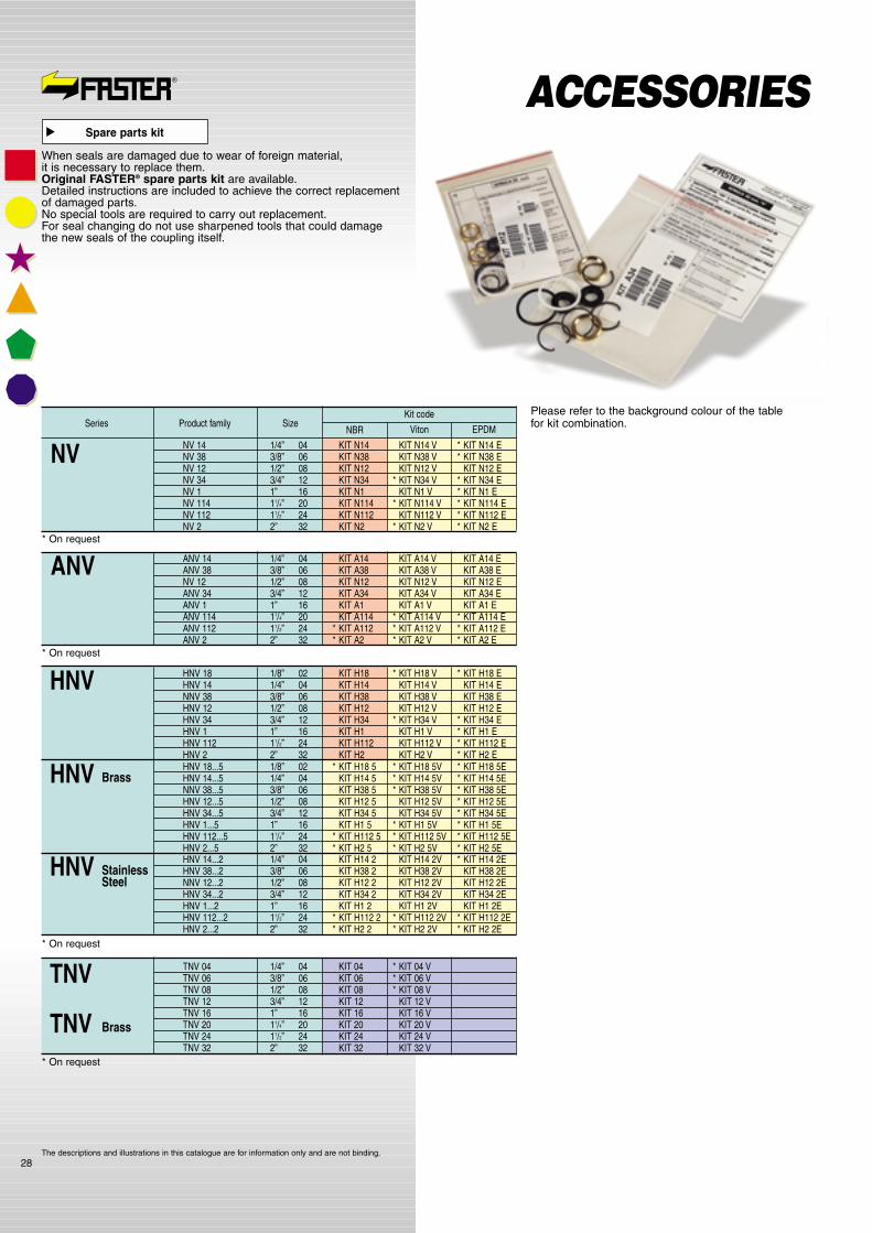
SizeProduct familySeriesKit code
NBR Viton EPDM
28
NV 14 1/4” 04 KIT N14 KIT N14 V * KIT N14 ENV 38 3/8” 06 KIT N38 KIT N38 V * KIT N38 ENV 12 1/2” 08 KIT N12 KIT N12 V KIT N12 ENV 34 3/4” 12 KIT N34 * KIT N34 V * KIT N34 ENV 1 1” 16 KIT N1 KIT N1 V * KIT N1 ENV 114 11/4” 20 KIT N114 * KIT N114 V * KIT N114 ENV 112 11/2” 24 KIT N112 KIT N112 V * KIT N112 ENV 2 2” 32 KIT N2 * KIT N2 V * KIT N2 E
NV
HNV 18 1/8” 02 KIT H18 * KIT H18 V * KIT H18 EHNV 14 1/4” 04 KIT H14 KIT H14 V KIT H14 ENNV 38 3/8” 06 KIT H38 KIT H38 V KIT H38 EHNV 12 1/2” 08 KIT H12 KIT H12 V KIT H12 EHNV 34 3/4” 12 KIT H34 * KIT H34 V * KIT H34 EHNV 1 1” 16 KIT H1 KIT H1 V * KIT H1 EHNV 112 11/2” 24 KIT H112 KIT H112 V * KIT H112 EHNV 2 2” 32 KIT H2 KIT H2 V * KIT H2 E
HNV
TNV 04 1/4” 04 KIT 04 * KIT 04 VTNV 06 3/8” 06 KIT 06 * KIT 06 VTNV 08 1/2” 08 KIT 08 * KIT 08 VTNV 12 3/4” 12 KIT 12 KIT 12 VTNV 16 1” 16 KIT 16 KIT 16 VTNV 20 11/4” 20 KIT 20 KIT 20 VTNV 24 11/2” 24 KIT 24 KIT 24 VTNV 32 2” 32 KIT 32 KIT 32 V
TNV
HNV 18...5 1/8” 02 * KIT H18 5 * KIT H18 5V * KIT H18 5EHNV 14...5 1/4” 04 KIT H14 5 * KIT H14 5V * KIT H14 5ENNV 38...5 3/8” 06 KIT H38 5 * KIT H38 5V * KIT H38 5EHNV 12...5 1/2” 08 KIT H12 5 KIT H12 5V * KIT H12 5EHNV 34...5 3/4” 12 KIT H34 5 KIT H34 5V * KIT H34 5EHNV 1...5 1” 16 KIT H1 5 * KIT H1 5V * KIT H1 5EHNV 112...5 11/4” 24 * KIT H112 5 * KIT H112 5V * KIT H112 5EHNV 2...5 2” 32 * KIT H2 5 * KIT H2 5V * KIT H2 5E
HNV Brass
TNV Brass
HNV 14...2 1/4” 04 KIT H14 2 KIT H14 2V * KIT H14 2EHNV 38...2 3/8” 06 KIT H38 2 KIT H38 2V KIT H38 2ENNV 12...2 1/2” 08 KIT H12 2 KIT H12 2V KIT H12 2EHNV 34...2 3/4” 12 KIT H34 2 KIT H34 2V KIT H34 2EHNV 1...2 1” 16 KIT H1 2 KIT H1 2V KIT H1 2EHNV 112...2 11/2” 24 * KIT H112 2 * KIT H112 2V * KIT H112 2EHNV 2...2 2” 32 * KIT H2 2 * KIT H2 2V * KIT H2 2E
HNV StainlessSteel
* On request
* On request
* On request
Please refer to the background colour of the tablefor kit combination.
ANV 14 1/4” 04 KIT A14 KIT A14 V KIT A14 EANV 38 3/8” 06 KIT A38 KIT A38 V KIT A38 ENV 12 1/2” 08 KIT N12 KIT N12 V KIT N12 EANV 34 3/4” 12 KIT A34 KIT A34 V KIT A34 EANV 1 1” 16 KIT A1 KIT A1 V KIT A1 EANV 114 11/4” 20 KIT A114 * KIT A114 V * KIT A114 EANV 112 11/2” 24 * KIT A112 * KIT A112 V * KIT A112 EANV 2 2” 32 * KIT A2 * KIT A2 V * KIT A2 E
ANV* On request
ACCESSORIESSpare parts kit
�
When seals are damaged due to wear of foreign material,it is necessary to replace them.Original FASTER® spare parts kit are available.Detailed instructions are included to achieve the correct replacementof damaged parts.No special tools are required to carry out replacement.For seal changing do not use sharpened tools that could damagethe new seals of the coupling itself.
The descriptions and illustrations in this catalogue are for information only and are not binding.
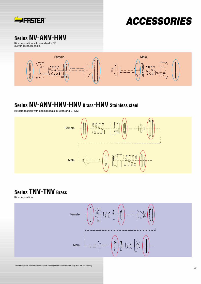
29
Series NV-ANV-HNVKit composition with standard NBR (Nitrile Rubber) seals.
Series NV-ANV-HNV-HNV Brass-HNV Stainless steelKit composition with special seals in Viton and EPDM.
Female Male
Female
Series TNV-TNV BrassKit composition.
Male
Female
Male
The descriptions and illustrations in this catalogue are for information only and are not binding.
ACCESSORIES
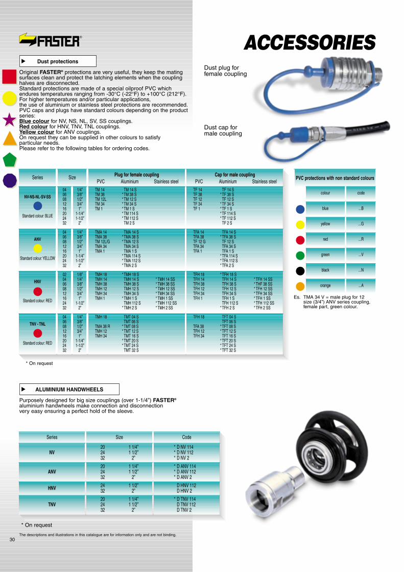
30
ACCESSORIES
Series Size Plug for female couplingPVC Aluminium Stainless steel
NV-NS-NL-SV-SS
Standard colour: BLUE
04060812 16 202432
1/4”3/8”1/2”3/4”1”
1-1/4”1-1/2”
2”
TM 14 TM 14 STM 38 * TM 38 STM 12L * TM 12 STM 34 * TM 34 STM 1 * TM 1 S
* TM 114 S* TM 112 S
TM 2 S
Cap for male couplingPVC Aluminium Stainless steel
PVC protections with non standard colours
TF 14 TF 14 STF 38 * TF 38 STF 12 TF 12 STF 34 * TF 34 STF 1 * TF 1 S
* TF 114 S* TF 112 S
TF 2 S
colour code
blue ...B
yellow ...G
red ...R
green ...V
black ...N
orange ...A
ANV
Standard colour:YELLOW
04060812 16 202432
1/4”3/8”1/2”3/4”1”
1-1/4”1-1/2”
2”
TMA 14 TMA 14 STMA 38 * TMA 38 STM 12L/G * TMA 12 STMA 34 TMA 34 STMA 1 TMA 1 S
* TMA 114 S* TMA 112 S* TMA 2 S
TFA 14 TFA 14 STFA 38 * TFA 38 STF 12 G TF 12 STFA 34 TFA 34 STFA 1 TFA 1 S
* TFA 114 S* TFA 112 S* TFA 2 S
HNV
Standard colour: RED
0204060812162432
1/8”1/4”3/8”1/2”3/4”1”
1-1/2”2”
TMH 18 * TMH 18 STMH 14 TMH 14 S * TMH 14 SSTMH 38 TMH 38 S * TMH 38 SSTMH 12 TMH 12 S * TMH 12 SSTMH 34 TMH 34 S * TMH 34 SSTMH 1 * TMH 1 S * TMH 1 SS
TMH 112 S * TMH 112 SS* TMH 2 S * TMH 2 SS
TFH 18 * TFH 18 STFH 14 TFH 14 S * TFH 14 SSTFH 38 TFH 38 S * THF 38 SSTFH 12 TFH 12 S * TFH 12 SSTFH 34 TFH 34 S * TFH 34 SSTFH 1 TFH 1 S * TFH 1 SS
TFH 112 S * TFH 112 SS* TFH 2 S * TFH 2 SS
TNV - TNL
Standard colour: RED
04060812 16 202432
1/4”3/8”1/2”3/4”1”
1-1/4”1-1/2”
2”
TMH 18 TMT 04 STMT 06 S
TMA 38 R * TMT 08 STMH 12 * TMT 12 STMH 34 TMT 16 S
* TMT 20 S* TMT 24 S
TMT 32 S
TFH 18 TFT 04 STFT 06 S
TFA 38 * TFT 08 STFH 12 * TFT 12 STFH 34 TFT 16 S
* TFT 20 S* TFT 24 S* TFT 32 S
* On request
Es. TMA 34 V = male plug for 12size (3/4”) ANV series coupling,female part, green colour.
Dust plug forfemale coupling
Dust protections
�
Original FASTER® protections are very useful, they keep the matingsurfaces clean and protect the latching elements when the couplinghalves are disconnected.Standard protections are made of a special oilproof PVC whichendures temperatures ranging from -30°C (-22°F) to +100°C (212°F).For higher temperatures and/or particular applications,the use of aluminium or stainless steel protections are recommended.PVC caps and plugs have standard colours depending on the productseries:Blue colour for NV, NS, NL, SV, SS couplings.Red colour for HNV, TNV, TNL couplings.Yellow colour for ANV couplings.On request they can be supplied in other colours to satisfyparticular needs.Please refer to the following tables for ordering codes.
Series
NV
ANV
HNV
TNV
* On request
Size Code
20 1 1/4”24 1 1/2”32 2”
20 1 1/4”24 1 1/2”32 2”
24 1 1/2”32 2”
20 1 1/4”24 1 1/2”32 2”
* D NV 114* D NV 112* D NV 2
* D ANV 114* D ANV 112* D ANV 2
D HNV 112D HNV 2
* D TNV 114D TNV 112D TNV 2
ALUMINIUM HANDWHEELS
�
Purposely designed for big size couplings (over 1-1/4”) FASTER®
aluminium handwheels make connection and disconnectionvery easy ensuring a perfect hold of the sleeve.
The descriptions and illustrations in this catalogue are for information only and are not binding.
Dust cap formale coupling

31
DECOMPRESSION VALVE
�
Features
�
This product has been studied in order to allow connectionand disconnection under full working pressure even with standardquick-release couplings not connectable under pressure.An additional feature is the possibility to use this product as a safetyrelief valve to decrease upstream pressure in case of emergency.VDM is extremely compact and is preassembled on threaded adaptorsof several sizes and types.The hose barb for the drain line is 360° swinging in orderto make the valve assembling in several positions easier.
SeriesVDM
* Safety factor = 1:4 - For static pressure safety factor 1:2
* Other versions on request
Max. work pressure*
Minimum burst pressure
MPa PSI MPa PSI
35 5.075 140 20.300
Technical data
�
Materials:- High grade carbon steel.- Valve in steel.- Surface treatment: zinc plating and Cr III passivation.- Springs in C98 steel.Seals:Standard in oilproof NBR (Nitrile Rubber) and Polyurethane.Working temperatures:From -25°C (-13°F) to +100°C (+212°F).
Available items
�
Thread (male)Ø B
Thread standardsØ B
Lmm inc. mm inc. mm inc. mm inc.
H Ø C HEXItem code*
VDM 0/22-1/22 M22x1,5 ISO 6149-1 M22x1,5 ISO 6149-2 65 2,56 65 2,56 8 0,31 30 1,18
VDM 12N-1/12N 1/2” NPTF ANSI B 1.20.3 1/2” NPTF ANSI B 1.20.3 66,5 2,62 62 2,44 8 0,31 27 1,06
VDM 12N-1/12S 1/2” NPTF ANSI B 1.20.3 3/4”-16 UNF SAE J1926-3 58,6 2,3 62 2,44 8 0,31 27 1,06
VDM 34N-1/34S 3/4” NPTF ANSI B 1.20.3 1” 1/16-12 UN SAE J1926-3 64,6 2,54 69 2,72 8 0,31 34 1,34
Thread (female)Ø A
Thread standardsØ A
The descriptions and illustrations in this catalogue are for information only and are not binding.
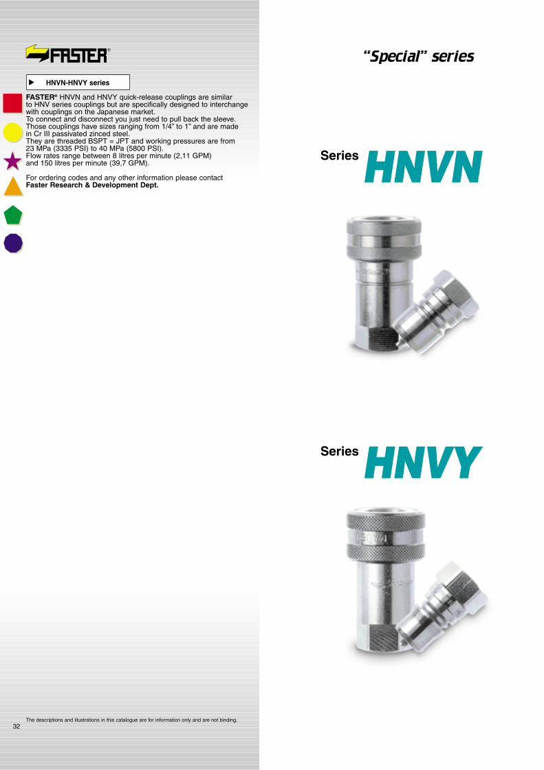
32
SeriesHNVY
SeriesHNVN
“Special” series
HNVN-HNVY series
�
FASTER® HNVN and HNVY quick-release couplings are similar to HNV series couplings but are specifically designed to interchangewith couplings on the Japanese market.To connect and disconnect you just need to pull back the sleeve.Those couplings have sizes ranging from 1/4” to 1” and are made in Cr III passivated zinced steel.They are threaded BSPT = JPT and working pressures are from 23 MPa (3335 PSI) to 40 MPa (5800 PSI).Flow rates range between 8 litres per minute (2,11 GPM) and 150 litres per minute (39,7 GPM).
For ordering codes and any other information please contact Faster Research & Development Dept.
The descriptions and illustrations in this catalogue are for information only and are not binding.

33
SeriesNVB
SeriesNZ
“Special” series
The descriptions and illustrations in this catalogue are for information only and are not binding.
NZ series
�
FASTER®’s NZ quick-release couplings are similar to NV series couplings but are specifically designed to interchange with couplings on the Newzealand market in transport field.To connect and disconnect you just need to pull back the sleeve.These couplings have sizes of 1” BSP threaded and are made in Cr III passivated zinced steel.The working pressures is of 23 MPa (3335 PSI) and flow rate is 160 litres per minute (42 GPM).
For ordering codes and any other information please contact Faster Research & Development Dept.
NVB series
�
FASTER®’s NVB quick-release couplings are similar to NV series couplings but are specifically designed to interchange with couplings on the American market. To connect and disconnect you just need to pull back the sleeve. NVB series couplings are also available with a safety lock.These couplings have sized of 1/4” BSP, BSPT. NPTF and SAE threaded and are made in Cr III passivated zinced steel.The working pressure is of 40 MPa (5800 PSI) and flow rate is 8 litres per minute (2,11 GPM).
For ordering codes and any other information please contact Faster Research & Development Dept.
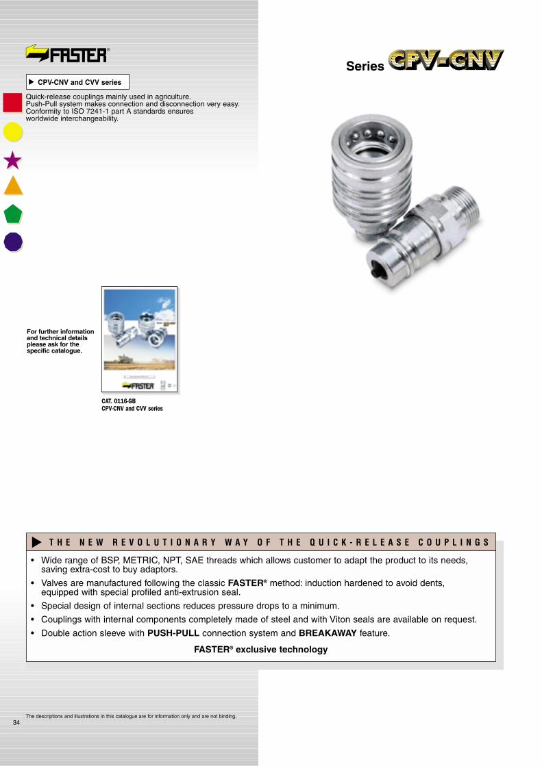
34
SeriesCPV-CNV and CVV series
�
Quick-release couplings mainly used in agriculture.Push-Pull system makes connection and disconnection very easy.Conformity to ISO 7241-1 part A standards ensuresworldwide interchangeability.
The descriptions and illustrations in this catalogue are for information only and are not binding.
�
For further informationand technical detailsplease ask for thespecific catalogue.
• Wide range of BSP, METRIC, NPT, SAE threads which allows customer to adapt the product to its needs, saving extra-cost to buy adaptors.
• Valves are manufactured following the classic FASTER® method: induction hardened to avoid dents, equipped with special profiled anti-extrusion seal.
• Special design of internal sections reduces pressure drops to a minimum.
• Couplings with internal components completely made of steel and with Viton seals are available on request.
• Double action sleeve with PUSH-PULL connection system and BREAKAWAY feature.
FASTER® exclusive technology
T H E N E W R E V O L U T I O N A R Y W A Y O F T H E Q U I C K - R E L E A S E C O U P L I N G S
�
CAT. 0116-GB CPV-CNV and CVV series

35The descriptions and illustrations in this catalogue are for information only and are not binding.
Agricultural series
�
This series of quick-release couplings has been specifically designed and produced for agricultural applications.Most couplings of this series are interchangeable and are used by most major manufacturers of tractors and agricultural machines in the world.The conformity to ISO 7241-A Standard assures a perfect interchangeability between agricultural machines in the world.The VF series conforms to ISO 5676 Standards.It is produced to connect the hydraulic brake systems and is used in all Europe.
1) Allows the connection with the male part under pressure (3 series).
2) Push-Pull connection.
3) The disconnection is achieved by pulling back the male part (BREAKAWAY feature).
4) Direct application on the valve or to rigid tubes.
5) Mechanical block of valves is automatic and prevents return line shut down even at high flow rate.
6) Dimensionally compact.
7) Wide range of threads.
T H E N E W R E V O L U T I O N A R Y W A Y O F T H E Q U I C K - R E L E A S E C O U P L I N G S
�
For further informationand technical detailsplease ask for thespecific catalogue.
CAT. 0112-GB Agricultural series
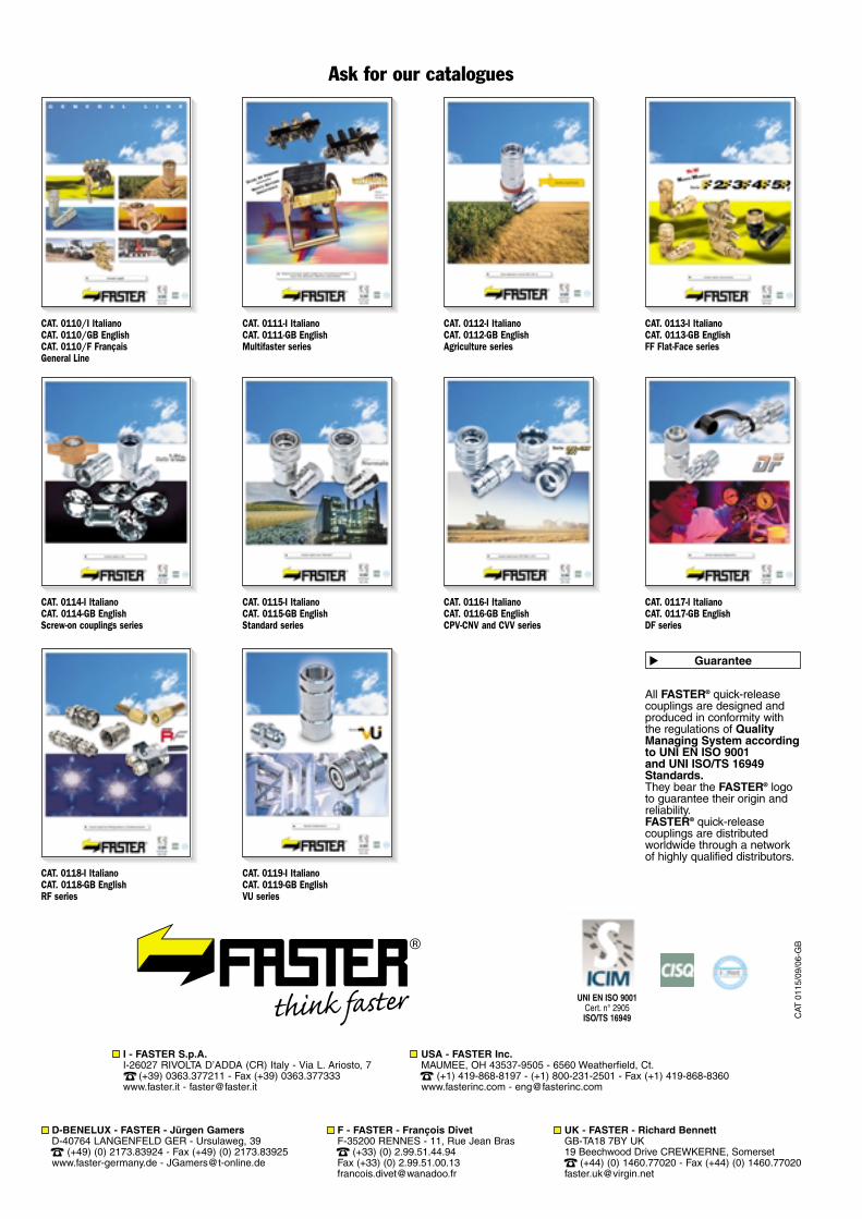
All FASTER® quick-releasecouplings are designed andproduced in conformity withthe regulations of QualityManaging System accordingto UNI EN ISO 9001and UNI ISO/TS 16949Standards.They bear the FASTER® logoto guarantee their origin andreliability.FASTER® quick-releasecouplings are distributedworldwide through a networkof highly qualified distributors.
Guarantee
�
Ask for our catalogues
CAT. 0113-I ItalianoCAT. 0113-GB EnglishFF Flat-Face series
CAT
0115
/09/
06-G
B
CAT. 0112-I ItalianoCAT. 0112-GB EnglishAgriculture series
CAT. 0111-I ItalianoCAT. 0111-GB EnglishMultifaster series
CAT. 0110/I ItalianoCAT. 0110/GB EnglishCAT. 0110/F FrançaisGeneral Line
CAT. 0116-I ItalianoCAT. 0116-GB EnglishCPV-CNV and CVV series
CAT. 0115-I ItalianoCAT. 0115-GB EnglishStandard series
CAT. 0114-I ItalianoCAT. 0114-GB EnglishScrew-on couplings series
CAT. 0118-I ItalianoCAT. 0118-GB EnglishRF series
CAT. 0119-I ItalianoCAT. 0119-GB EnglishVU series
CAT. 0117-I ItalianoCAT. 0117-GB EnglishDF series
I - FASTER S.p.A.I-26027 RIVOLTA D’ADDA (CR) Italy - Via L. Ariosto, 7
(+39) 0363.377211 - Fax (+39) 0363.377333www.faster.it - [email protected]
D-BENELUX - FASTER - Jürgen GamersD-40764 LANGENFELD GER - Ursulaweg, 39
(+49) (0) 2173.83924 - Fax (+49) (0) 2173.83925www.faster-germany.de - [email protected]
UK - FASTER - Richard BennettGB-TA18 7BY UK19 Beechwood Drive CREWKERNE, Somerset
(+44) (0) 1460.77020 - Fax (+44) (0) [email protected]
F - FASTER - François DivetF-35200 RENNES - 11, Rue Jean Bras
(+33) (0) 2.99.51.44.94Fax (+33) (0) [email protected]
USA - FASTER Inc.MAUMEE, OH 43537-9505 - 6560 Weatherfield, Ct.
(+1) 419-868-8197 - (+1) 800-231-2501 - Fax (+1) 419-868-8360www.fasterinc.com - [email protected]
UNI EN ISO 9001Cert. n° 2905ISO/TS 16949


