Download - FE am w 2013 ics

FE Exam Review 2013Statics
B i C PhDBrittany Coats, PhDMechanical Engineering Dept.

Scalars have a magnitude
Vectors have a magnitude & direction

Vector PrinciplesVector Principles
2 Vector Addition2. Vector Addition
RBA
Graphically identify R using the parallelogramlaw B
R ORA
RAA
R OR
B
R
BB

Vector PrinciplesVector Principles
3 Vector Subtraction3. Vector Subtraction
ABR ABR )(OR
Same as vector addition, but 1 is multiplied to
)(
one of the vectorsB
RB
AR

Solving for the ResultantSolving for the Resultant
Graphical Solution:Graphical Solution:law of sines:
CBAsinsinsin
law of cosines:
CBA
cos2222 ABBAC
B
AC
A

Rectangular ComponentsRectangular Components
Fx = Fcos
Fy = Fsin
Fx & Fy are still vectors w/ a magnitude & direction.
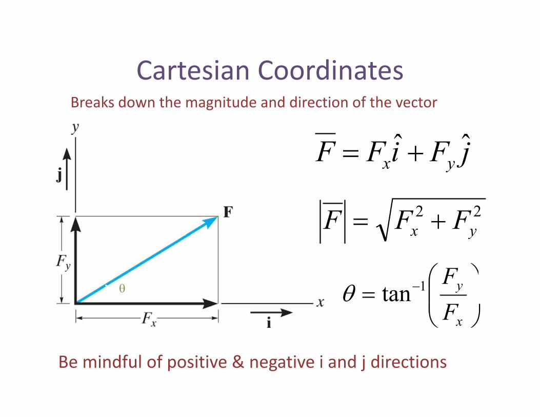
Cartesian CoordinatesCartesian CoordinatesBreaks down the magnitude and direction of the vector
jFiFF yxˆˆ
22yx FFF yx
yF1tx
y
F1tan
Be mindful of positive & negative i and j directions

Cartesian Vector �– 3DCartesian Vector 3D
jAiAA ˆˆ kA ˆjAiAA yx kAz
222zyx AAAA
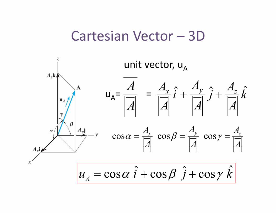
Cartesian Vector �– 3DCartesian Vector 3D
unit vector uAunit vector, uA
Au = = kAj
AiA zyx ˆˆˆ
AuA= = k
Aj
Ai
Azyx
AA
AA
AA zyx coscoscos
AAA
kjiu ˆcosˆcosˆcos kjiuA coscoscos

Position VectorsPosition Vectorsz
B (xB, yB, zB)kzjyixrA ˆˆˆ
A (x y z ) r
kzjyixr AAAA
k̂ˆˆrAB
y
A (xA, yA, zA)
rA
rBkzjyixr BBBB
x
y
kzzjyyixxr ABABABABˆˆˆ

Define force vectorffrom position vector
Define the vector, F, using the providedi d f h f d h i imagnitude of the force and the position
vector to determine the direction.
Magnitude = F (given)g (g )Direction = same as position vector from A to B
Step 1: Find the unit vector from the
rruu rF
position vector
rStep 2: Multiply unit vector by forcemagnitude
ruFF

Dot ProductDot Product
Fi d l b t t tCan be used to:
�• Find angle between two vectors�• Find a force perpendicular ( ) or parallel(||) to a line
cosBABA cosBABA
AA
B

Dot ProductcosBABA
Dot Productki j = 0 i i = 1
j
jj k = 0k i = 0
j j = 1k k = 1
i
kAjAiAA ˆˆˆ kBjBiBB ˆˆˆkAjAiAA zyx kBjBiBB zyx
ˆˆ )ˆˆˆ()ˆˆˆ( kBjBiBkAjAiABA zyxzyx
zzyyxx BABABABA

Dot Product Applications1. Angle between two vectors:
Dot Product Applications
2. Component of a vector || to a linecosBABA
2. Component of a vector || to a line(projection of a vector on a line)
uAAA cos3. Component of vector to a line
aa uAAA cos||
sinAA a
22AAA 2||aa AAA
A||
a

MomentsMoments
Moment arm
M = FdM0= Fd

Moment DirectionMoment Directionz Use right hand rule
+M: thumb points indirection of positive axis (3D)OR thumb points out of the
y
x
OR thumb points out of thepage (2D).
x
M: thumb points in directiony
of negative axis (3D) ORthumb points into the page(2D)
x
(2D).

Calculating MomentsCalculating MomentsMo = r x Fo

Cross ProductCross Product�• Always results in a vector.�• Resulting vector is always perpendicularto the two originating vectors.
ABuBABxA )sin( AB
A
BB

Cross ProductCross Productki x j = k i x i = 0
j
jj x k = ik x i = j
j x j = 0k x k = 0
ij x i = kkk x j = ii x k = j
ABuBABxA )sin( AB)(

Resultant MomentsResultant Moments
F F
O
F1 F3
d
d3
O d1
F2d2
332211 dFdFdFMO 332211O

Resultant MomentsResultant Moments
F F
O
F1 F3r1
r3O
F2
r2
)()()( 332211 FxrFxrFxrMO )()()(O

Moment about AxisMoment about Axisaa FdM
)(ˆ FM )(ˆ FxruM aa
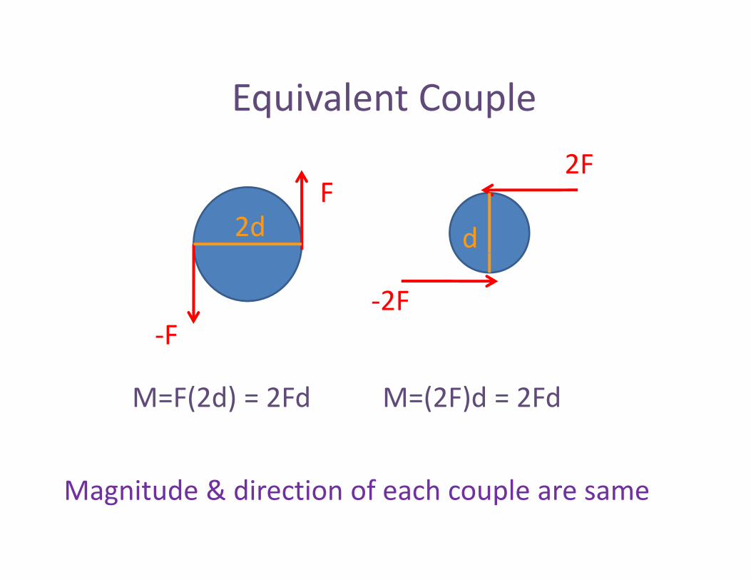
Equivalent CoupleEquivalent Couple2F
Fd2d
2FFF
M=F(2d) = 2Fd M=(2F)d = 2FdM=F(2d) = 2Fd M=(2F)d = 2Fd
Magnitude & direction of each couple are same

Equivalent Force Moment SystemsEquivalent Force Moment Systems
FFd
F1F1
M=F1d
O
1
FFF1
dFM
FF1
dFMO 1

Distributed LoadsDistributed Loads
AdAdF )(xR
FR
AdAdxxwFALr )(
xdAdxxxw )(
R
A
A
L
LR dA
xdA
dxxw
dxxxwx
)(
)(
FR
AL

Equilibrium:Equilibrium:
bj t t t ill t t tobject at rest will stay at restOR
object with a constant velocityill t t th t t t l itwill stay at that constant velocity
F0
F = ma
F 0F = 0

EquilibriumEquilibrium�• Draw free body diagram (FBD)�• Sum up all the forces and set equal tozero F = F i + F j+ F k = 0zero
�• Sum up all the moments and set equal tozero
F = Fxi + Fyj+ Fzk = 0
zeroM = Mxi+ Myj+ Mzk = 0
Mx = 0My = 0
Fx = 0Fy = 0y
Mz = 0yFz = 0

Free body diagramsFree body diagrams
Find all forces acting at AFind all forces acting at A
TAD
AA
TACTAB
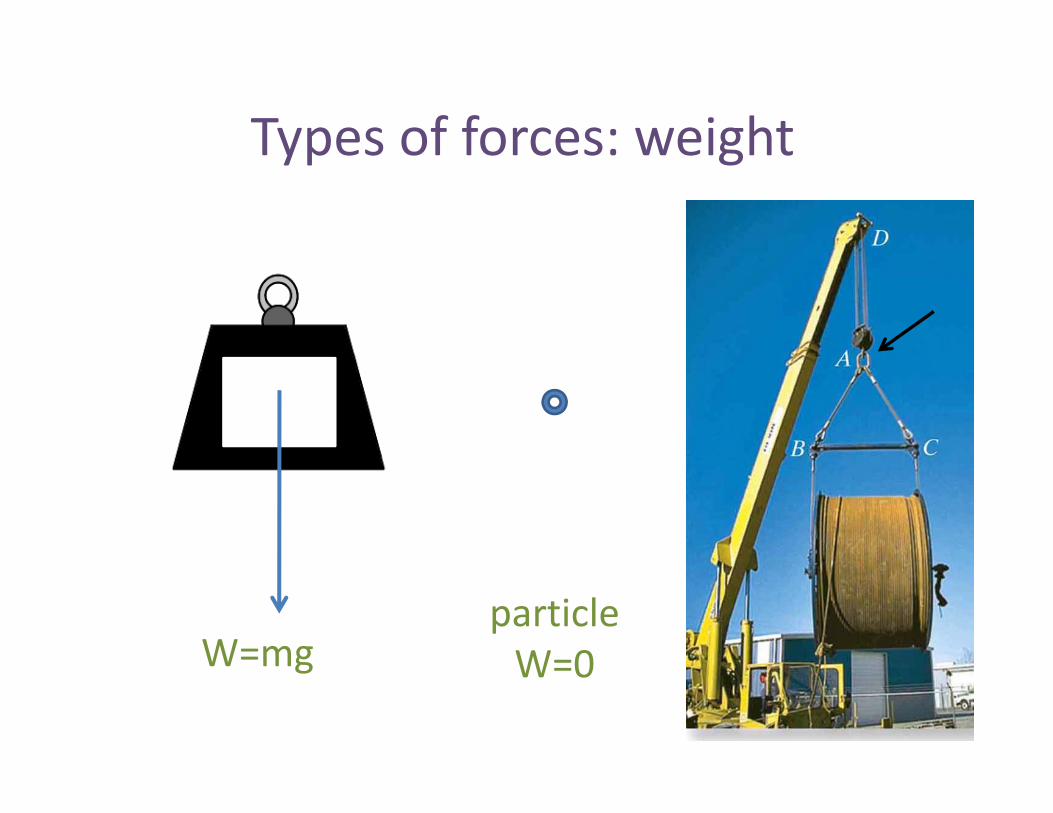
Types of forces: weightTypes of forces: weight
W=mgparticleW=0W mg W=0

Types of forces: cables/ropesTypes of forces: cables/ropes
C bl l i t iCables are always in tension

Types of forces:bl f l llcables in frictionless pulleys
C bl l i t i
TT W
Cables are always in tension
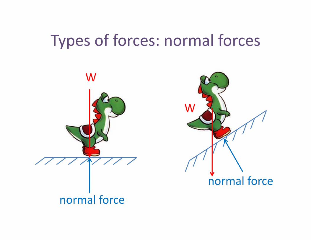
Types of forces: normal forcesTypes of forces: normal forces
WW
WW
l fnormal force
normal force

Types of forces: springsTypes of forces: springs
F=ksF=ksk= spring constant
s=lengthfinal �– lengthinitial
+s:+s:
s:

Reaction forcesReaction forcesReaction forces resist translation or rotation
Rx
Ryroller pinRy
RyRx
M
roller onangle
fixed supportRyangle
R

Trick #1 �– Two Force MemberTrick #1 Two Force MemberIf only two forces act on a rigid body, they must beequal and opposite in magnitude and act along theequal and opposite in magnitude, and act along the
same line of action

Trick #2 �– Three Force MemberTrick #2 Three Force MemberIf three forces act on a rigid body, they must be either
concurrent or parallelconcurrent or parallel

EquilibriumEquilibriumExample:

Free Body DiagramsFree Body DiagramsExample:

TrussesTrusses�• Loads are applied to the joints�• Members are attached with smooth pins�• Weight of members is considered small�• Weight of members is considered smallcompared to loads being appliedSt t k th i id�• Structure makes them rigid
�• Each member must beunder compression ortension

Solve for Reaction ForcesSolve for Reaction Forces
Axx
Ay Cy
Draw FBD of entire truss

Solve for Internal ForcesSolve for Internal ForcesUsing Method of Joints
B 500 N
FBA
FBA FBC A
BA
FACAx
Ax
Ay
C
FBC
x
Ay Cy
C
FAC
Cy
Create equilibrium equations for each joint

Method of SectionsMethod of Sections

Zero Force MembersZero Force Members
Rule #1: If there are only 2 members acting on a jointand no external forces (applied or reaction), then thoseand no external forces (applied or reaction), then those
members have zero force.

Zero Force MembersZero Force Members
Rule #2: If there are only 3 members acting on a joint (andno applied or reaction forces) and two members arepp )
collinear, then the 3rd member has zero force.
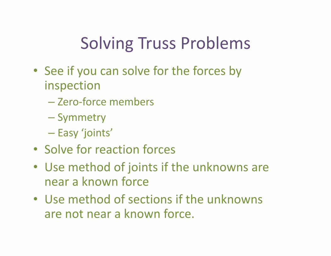
Solving Truss ProblemsSolving Truss Problems�• See if you can solve for the forces byinspection�– Zero force members�– Symmetry�– Easy �‘joints�’
�• Solve for reaction forces�• Use method of joints if the unknowns arenear a known force
�• Use method of sections if the unknownsare not near a known force.

Frames & MachinesFrames & Machines
F
FAB
FAB
FAB

Internal ForcesInternal Forces
BB
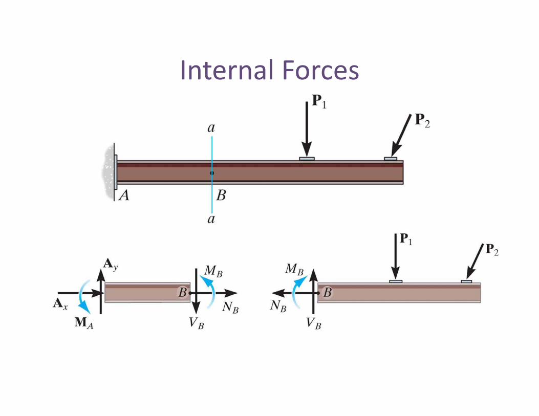
Internal ForcesInternal Forces

Internal Forces (3D)Internal Forces (3D)

Load, Shear, Moment Relationships
Shear changes by the15 N10 N
g ymagnitude and direction ofconcentrated load.14 N11 N
11 N
14 N1 N Moment change is equal tothe area under the shearthe area under the shearcurve.
1 N*m
Slope of shear is equal tointegral of load, slope of
11 N*m 14 N*m
moment is equal to integralof shear.

Load, Shear, Moment Relationships
Addition of a moment9 N/m10 N
makes the moment diagramjump by the magnitude17 N11 N
2 N*m
11 N1 N 1 N
9 N Shear is integral ofdistributed load, moment isi l f h
12 N*m11 N*m integral of shear.11 N*m
10 N*m
11 N m

FrictionFriction�• A force that opposes motion or potentialmotion between two contacting surfaces
f
N
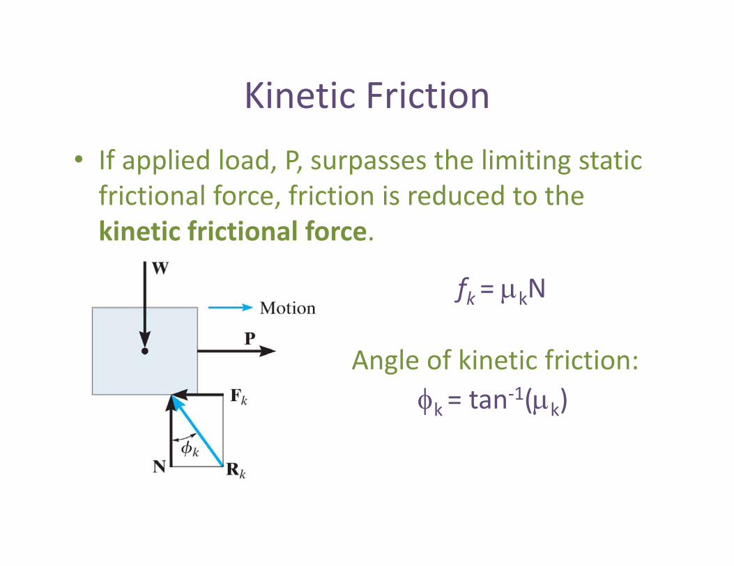
Kinetic FrictionKinetic Friction�• If applied load, P, surpasses the limiting staticfrictional force, friction is reduced to thekinetic frictional force.
fk = kN
1( )Angle of kinetic friction:
k = tan 1( k)

Friction vs. Applied LoadFriction vs. Applied Load

Friction ProblemsFriction Problems�• Equilibrium: What is the frictional force?
Check that Fa ANA and Fc CNC

Friction ProblemsFriction Problems�• Impending motion at all contact points: Whatis the smallest angle that a ladder can beplaced along a wall?

Friction ProblemsFriction Problems�• Impending motion at a single contact point:What is the minimum applied load thatneeded to cause motion anywhere?

WedgesWedges�• Transform an applied force into a much largerforces at approximately a right angle to theapplied force.

Flat Belt FrictionFlat Belt Friction

Flat Belt FrictionFlat Belt Friction
eTT eTT 12
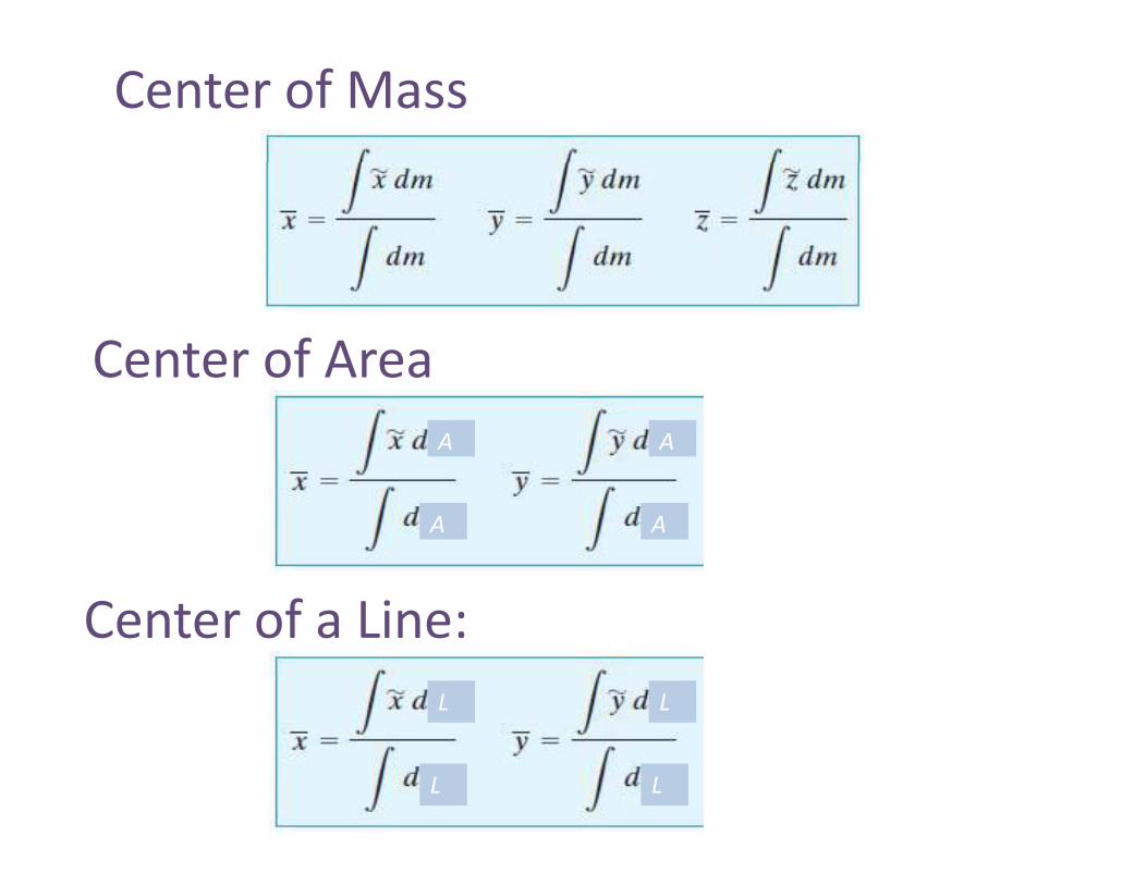
Center of Mass
Center of AreaA A
AA
C t f LiCenter of a Line:L L
LL

Identifying Centroids LineIdentifying Centroids Line
�• Pick your differential element
�• Identify a relationship of dL to dx and dy
y
22 dydxdL
�• Identify a relationship of dxto dy
ydydx 2�• Plug into our equations forx and y centroid

Identifying Centroids AreaIdentifying Centroids Area�• Pick your differential element�• Identify a relationship of dA to dx or dy
xdydA xdydA
�• Plug into our equationsg qfor x and y centroid

Centroids �– composite bodiesCentroids composite bodies

Moments of Inertia (I)Moments of Inertia (I)
2dAyIx2
dAxI y2
dArJo2
o
IIJ yxo IIJ

Parallel Axis TheoremParallel Axis Theorem
22' yxx AdII
2' xyy AdII
'' yxC IIJ y
2AdJJ CO AdJJ CO

Radius of GyrationRadius of Gyration
AIk x
xAI
k yyA Ay
Jk o
Ako

Moment of Inertia compositeMoment of Inertia composite1) Compute moment of inertia for
each segment.2) Add up moment of inertias�…) p
BUT�…they must be about thesame axis in order to add them up!same axis in order to add them up!

Moments of InertiaMoments of Inertia
Example 2:Example 2:
Determine the moment of inertia of the cross sectional areaof the channel with respect to the x axis


