
“Fiber 101”
Tom WarrenApplications Engineering

Today’s Speaker
Tom WarrenApplications Engineering
Clearfield®
• Worked in Communication Industry for 15 years
• Specializes in passive connectivity products for CWDM, DWMD, FTTx and HFC applications
• SCTE Member North Country Region

Agenda
1. Fiber Basics, Transmitters/Receivers, LASERs and LEDs
2. Transmission Characteristics
3. Optical Loss Budgets, Testing/Inspection
4. Fiber Management and Maintenance
5. HFC Applications
6. Advanced Optical Systems
– FTTx, PON, RFOG, WDM’s
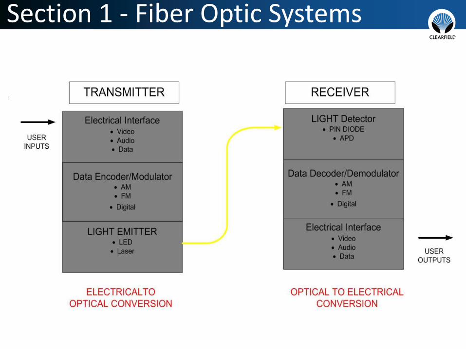
Section 1 - Fiber Optic Systems

Fiber Optic Basics
Why do we use it?

LONG HAUL TELECOM HFC
WIND FARM/POWER D.O.T. APPLICATIONS
FTTx
CELL BACKHAULD.O.T.
Applications for Fiber Optics

How Fiber Works (Total Internal Reflection)
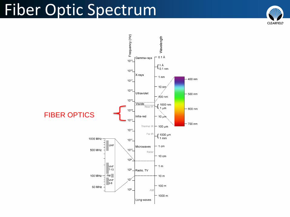
Fiber Optic Spectrum
FIBER OPTICS

Commonly Used Wavelengths
1310nm 1550nm

Types of Fiber (Multi-Mode)
Multimode fiber: has a bigger core (almost always 62.5 microns - a micron is one millionth of a meter - but sometimes 50 microns) and is used with LED sources at wavelengths of 850 and 1300 nm for short distance, lower speed networks like LANs.
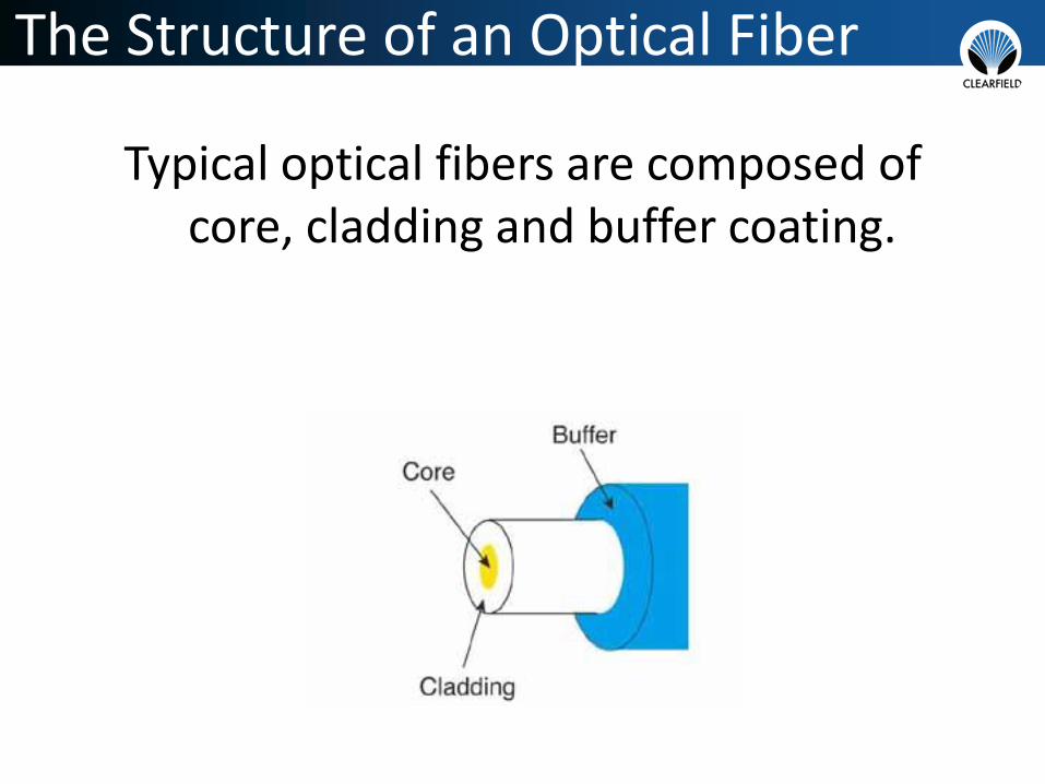
The Structure of an Optical Fiber
Typical optical fibers are composed of core, cladding and buffer coating.

Types of Fiber (Singlemode)
Singlemode fiber: has a much smaller core, only about 9 microns, and is used for telephony and CATV with laser sources at 1310, 1490, 1550 and 1625nm. It can go very long distances at very high speeds.

The Structure of an Optical Fiber
SINGLEMODE
Core 8 – 10 micron
Cladding 125 micron

Fiber Optic Color Code
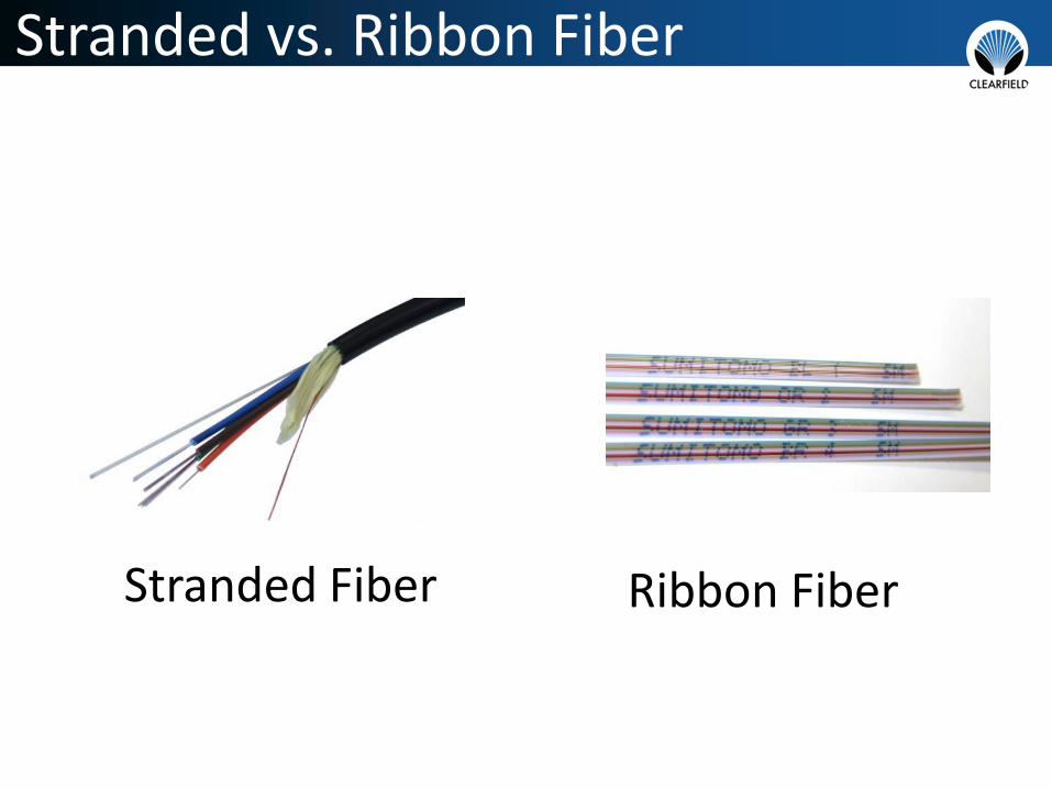
Stranded vs. Ribbon Fiber
Ribbon FiberStranded Fiber

Transceivers
SFP GBIC
VARIOUS WAVELENGTHS
VARIOUS DISTANCES

Section 2 – Fiber Transmission Characteristics
• Absorption
• Scattering
• Micro/Macro Bending

Absorption

Scattering
Light Scatter
Light Scatter
Light Scatter

Micro Bends/Macro Bends
Macrobend

Section 3: Optical Link/Power Budget

Connector Loss Attenuation

Singlemode Fiber Connectors

UPC vs. APC Close Up

Connector Types (UPC and APC)
Splice Loss Attenuation

Fiber Cable Distance Attenuation
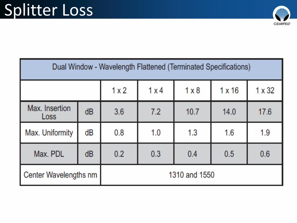
Splitter Loss

CWDM Loss

Loss Budget Equation
Number of Connectors x Loss per Connector
+
Number of Splices x Loss per splice
+
Length of Fiber in Km x Loss per Km
+
Number of Optical Components x Loss per Component
+
Margin
=
Total Loss

Real World Example
1550nm 23KM link with four SCAPC mated pairs,
four splices and two 8 channel CWDM’s:
Connector Loss : 0.3dB x 4 1.2 dB
Splice Loss: .02 x 4 .08 dB
Length Loss 0.22dB/Km x 23Km 5.06 dB
CWDM Loss: 3.0dB x 2 6 dB
System Margin: 3dB 3 dB
Total Loss: 16.06 dB

Light Source/Meter

OTDR
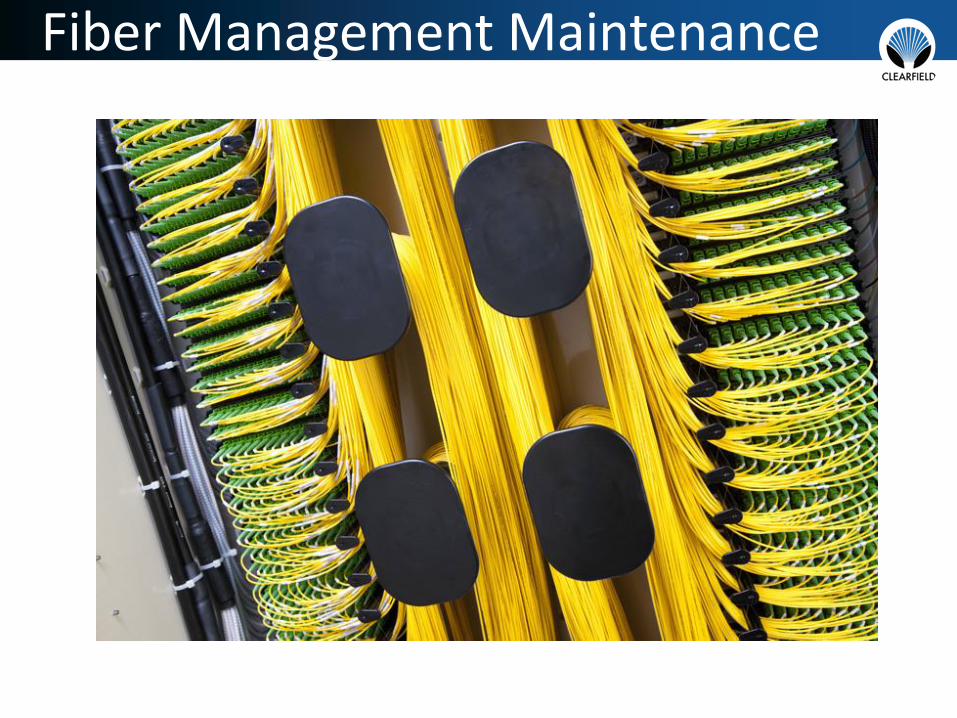
Fiber Management Maintenance

Bend Radius

Pile Up Specifications
• Telcordia standard (GR-449) states that fiber cable build-up should never exceed two inches in depth at any point within the fiber network.
• 44 x 3mm Jumpers per square inch
• 102 x 2mm Jumpers per square inch
• 142 x 1.7mm Jumpers per square inch

Trough Pile-Up Guidelines
• 3” H x 5” D Trough can handle
–1420 x 1.7mm Jumpers
–1020 x 2mm Jumpers
–440 x 3mm Jumpers

Fiber Management Basics
• Access
• Bend Radius Protection
• Physical Fiber Protection
• Route Diversity
• Density
• Labeling/Port Identification

Fiber Management Basics – Must Haves
• Access–Clear circuit access to jumpers and both
sides of adapter– Easy access improves bend radius
protection–Minimal live circuit disturbance– Improves configuration time

Fiber Management Basics – Must Haves
• Bend Radius Protection–GR-449
–Prevent micro and macro bends
– Long term reliability
– Improper radius is a critical point of failure over time

Fiber Management Basics – Must Haves
• Physical Fiber Protection
–Physical protection of fibers when not being accessed
–Accidental damage

Fiber Management Basics – Must Haves
• Route Diversity
–Multiple routes reduce pile-up
–Congestion causes confusion
– Improves access

Fiber Management Basics – Must Haves
• Density
–Whose definition?
– Sacrifices
–Maintain protection

Labeling/Fiber Identification

Fiber Management/Maintenance Summary
• Bend radius protection
• Keep it clean
• Inspect it
• Identify it

Current and Future Fiber Applications
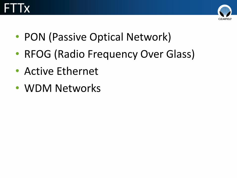
FTTx
• PON (Passive Optical Network)
• RFOG (Radio Frequency Over Glass)
• Active Ethernet
• WDM Networks
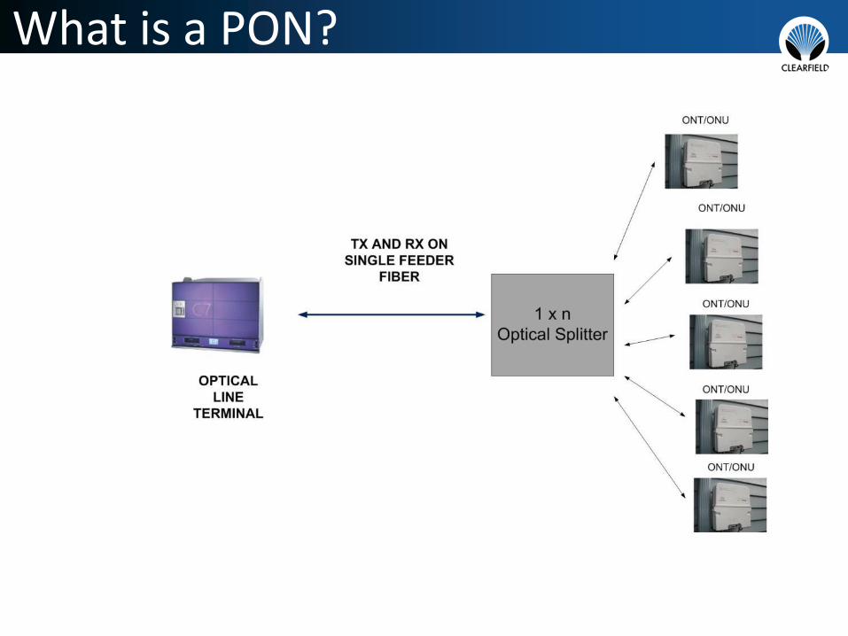
What is a PON?

ONT (Optical Network Terminal)
SINGLE FAMILY ONT MDU FAMILY ONT
Advantages of PON and RFOG
• No Actives in the field
• No Network Powering or Batteries in OSP
• High Bandwidth
• Lower Maintenance Costs
PON Splitting Architectures
• Centralized split
• Home run
• Distributed split
• Tapped splitters
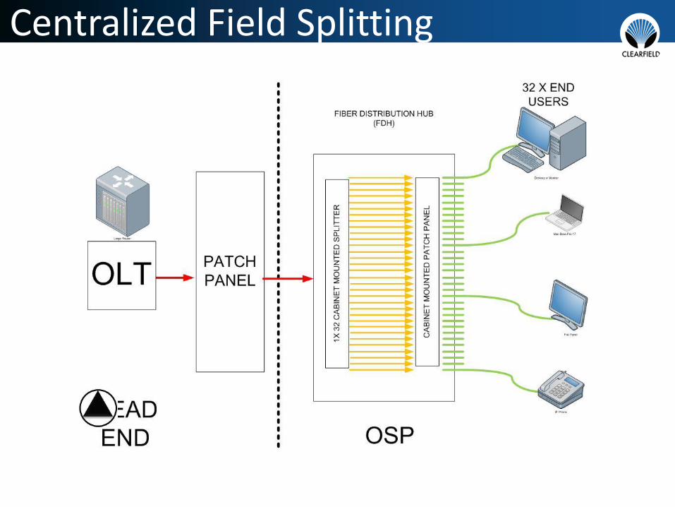
Centralized Field Splitting

Centralize Field Split Picture
1x32 Splitter with pre-terminated legs

“Home Run” PON Architecture

FTTH Home Run Frame
1x32 adapter splitter mounted in frame in
Head End
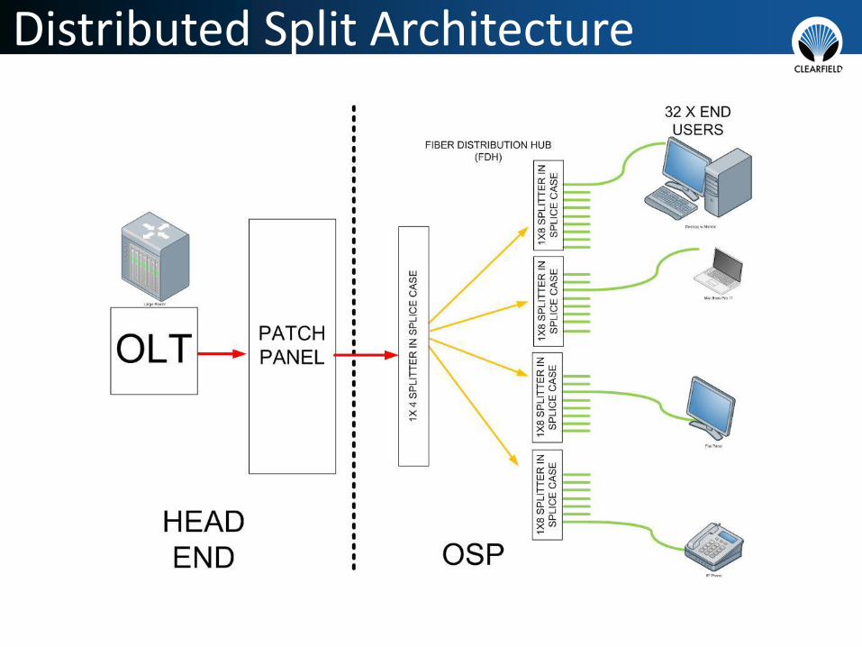
Distributed Split Architecture

Distributed Split Picture
RUGGEDIZED SPLITTER
BARE/RAW SPLITTER

Tapped Optical Splitter Architecture

Active Ethernet FTTH
• 1:1 Fiber to Subscriber ratio
• Expensive• Scalable –
each sub has port on router in Head End/CO

WDM Technology
Legacy Technology
WDM Technology

Fiber Exhaust
(What we need now)(What we DID put in)
Contact Information
Tom Warren, CFHP
Applications Engineering
Clearfield®, Inc.
email: [email protected]
office: 763-519-9759
cell: 763-232-0278


