
FIBER RANDOM GRATING AND ITS
APPLICATIONS
by
Yanping Xu
Thesis submitted to the Faculty of Graduate and Postdoctoral Studies
In partial fulfillment of the requirements for the Degree of Doctor of Philosophy
in Physics
Ottawa-Carleton Institute for Physics University of Ottawa
Ottawa, Ontario, Canada
© Yanping Xu, Ottawa, Canada, 2017

To my family
ii

Abstract
Femtosecond (fs) laser micromachining has been a useful technique either to modify
and remove materials or to change the properties of a material, and can be applied to
transparent and absorptive substances. Recently high-power fs laser radiation has drawn
intensive attention for the induction of refractive index change to fabricate micro-structures
in dielectric materials. This thesis studies the optical properties of a novel fiber random
grating fabricated by fs laser micromachining technique and extends its applications from
optical sensing to random fiber lasers and optical random bit generations.
The thesis mainly consists of three parts. In the first part, the physical mechanism
behind the fs laser micromachining technique and the fabrication of the fiber random grating
are introduced. By employing a wavelength-division spectral cross-correlation algorithm, a
novel multi-parameter fiber-optic sensor based on the fiber random grating is proposed and
demonstrated to realize simultaneous measurements of temperature, axial strain, and
surrounding refractive index.
In the second part, Brillouin random fiber laser (BRFL) and Erbium-doped fiber random
laser (EDFRL) are introduced, respectively. Firstly, we propose a novel Brillouin random
fiber laser with a narrow linewidth of ~860 Hz based on the bi-directionally pumped
stimulated Brillouin scattering (SBS) in a 10-km-long optical fiber. A random fiber Fabry-
Perot (FP) resonator is built up through the pump depletion effects of SBS at both ends of the
fiber. The novel laser is successfully applied for linewidth characterization beyond 860 Hz of
light source under test. Secondly, the random grating-based FP resonator is introduced to
build up a novel BRFL with narrow-linewidth of ~45.8Hz and reduced lasing threshold. The
iii

intensity and frequency noises of the proposed random laser are effectively suppressed due to
the reduced resonating modes and mode competition. Finally, the fiber random grating is
used as random distributed feedback in an EDFRL to achieve both static (temperature, strain)
and dynamic (ultrasound) parameter sensing. Multiple lasing lines with high signal-to-noise
ratio (SNR) up to 40dB are achieved, which gives an access for a high-fidelity multiple-
static-parameter sensing application. By monitoring the wavelength shifts of each peak,
temperature and strain have been simultaneously measured with small errors. The fiber
random grating in the EDFRL is also able to sense the ultrasound waves. By achieving single
mode lasing with the EDFRL, ultrasound waves with frequencies from 20kHz to 0.8MHz
could be detected with higher sensitivity and SNR improvement up to 20dB compared with
conventional piezoelectric acoustic sensors.
In the third part, we demonstrate that a semiconductor laser perturbed by the distributed
feedback from a fiber random grating can emit light chaotically without the time delay
signature (TDS). A theoretical model is developed by modifying the Lang-Kobayashi model
to numerically explore the chaotic dynamics of the laser diode subjected to the random
distributed feedback. It is predicted that the random distributed feedback is superior to the
single reflection feedback in suppressing the TDS. In experiments, The TDS with the
maximum suppression is achieved with a value of 0.0088, which is the smallest to date.
iv

Acknowledgments
It has been almost six years since I joint the Fiber Optics Group in University of Ottawa.
During this long journey pursuing for my Ph.D., I have grown up from a boy dreaming to be
a scientist to a man with abilities to conduct research. There were moments of frustration and
moments of happiness interwoven in this period, but most impressively, moments of self-
recognition and enjoying the scientific research. This thesis cannot be finished without the
help of many people contributed in many ways. I’m so honored to have this opportunity to
thank all the people who have helped me over the past six years. I will cherish this
unforgettable experience forever.
First of all, I would like to sincerely thank my supervisors, Prof. Xiaoyi Bao and Prof.
Ping Lu, for their careful guidance and support in my graduate study. It is my great honor to
know Prof. Bao and Prof. Lu both at professional and personal level. Prof. Bao, with her
strong passion, broad knowledge and thoughtful insight in research, impresses me a lot. Her
creative ideas, rigorous attitude and rich research experience have taught and inspired me to
challenge the useful but difficult research topics one by one. Prof. Lu provided me not only a
lot of insightful and helpful suggestions and ideas during my research process, but also
invaluable kind care with my daily lives. His encouragement and constant support greatly
increase my confidence in research and contribute to my successful completion of Master
and Ph.D. studies. I would also express my great gratitude to Prof. Liang Chen for his
precious advices and instructive discussions, which significantly improves the quality of this
thesis. I also thank Prof. Stephen Mihailov in National Research Council Canada for his help
in experimental arrangements for device fabrication and valuable suggestions and revisions
v

on research topics and manuscripts.
Many thanks are given to Dr. Ping Lu for his great ideas, useful suggestions and
thoughtful discussions. Dr. Lu has provided much assistance and guidance when I started my
research. He is a kind and open-minded person who is always willing to share ideas and
launch discussions with me. It is no exaggeration to say that he helped me a lot to knock the
door for research and this thesis cannot be completed without his guidance.
I would like to specially thank Dr. Zengguang Qin. He is more than a research partner
but one of my sincere friends. His comments and suggestions have greatly benefited me
during my research. He was always with me whenever I got confused, lost and disappointed.
I would like to express my gratitude to Prof. Mingjiang Zhang, Dr. Yang Lu, and Prof.
Zhonghua Ou. They provided tremendous assistance and guidance with my researches and
experiments. It is a great pleasure to collaborate with them to work on several exciting
research projects.
I’m also thankful to Mr. Dao Xiang and Ms. Meiqi Ren, who have been my sincere
friends in the Fiber Optics group. We attended courses and conducted experiments together,
shared ideas and had discussions, and experienced lots of happy moments when participating
the NSERC CREATE SERA program. I also thank Mr. Song Gao and Dr. Liang Zhang for
helpful discussions and assistance when I’m depressed and confused.
I would like to acknowledge funding support by the NSERC CREATE SERA program
over the past three years. I thank the program director, Prof. Mark Green in Queen’s
University, for his constant help and support in the program and internship applications.
Special thanks will be given to Mr. Terry Gerritsen, Dr. Richard MacRosty, Mr. Ravi
Pula, and Mr. Jakob Janzen, my colleagues in Control Technologies of Hatch Ltd., where I
spent four months doing my internship. It is a memorable experience working in Hatch with
vi

such nice guys and I wouldn’t learn a lot without their advices and suggestions. In particular,
I would like to express my gratitude to John, who is the owner of the house where I lived in
Mississauga, for his kind encouragements and comforts when I was low during the internship.
I am thankful to all the other colleagues in Fiber Optics group — Prof. Zhengying Li,
Prof. Ping Han, Dr. Chen Wang, Mr. Bhavaye Saxena, Dr. Daisy Williams, Mr. Robert Chutu
Li, Dr. Yang Li, Dr. Qian He, Mr. Tian Wang, Prof. Chunhua Wang, Mr. Benoit Vanus. My
life in the laboratory was enriched by their company.
I am thankful to the former colleagues in Fiber Optics group during my Master studies
— Dr. Ganbin Lin, Mr. Jia Song, Dr. Wenhai Li, Dr. Xiaozhen Wang, Dr. Dapeng Zhou, Dr.
Meng Pang, Prof. Yuangang Lu, Mr. Jeremie Harris and Mr. Graeme Niedermayer for their
useful technical assistance and discussions.
Special thanks go to my fiancée Muzi Li for her love and support. Her encouragement
and understanding through the years allowed me to face challenges with great confidence.
Finally, I am deeply indebted to my family in China, especially my parents. It is their
encouragement, enduring love and understanding for me to pursue my graduate study.
It is impossible to remember all, and I apologize to those I have inadvertently left out.
Again, thank you all!
vii

Statement of originality
This work contains no material which has been accepted for the award of any other
degree or diploma in any university or other tertiary institution and, to the best of my
knowledge and belief, contains no material previously published or written by another person,
except where due reference has been made in the text.
I give consent to this copy of my thesis, when deposited in the University Library, being
available for loan and photocopying.
SIGNED: ………………………………..
DATE: …………………………………...
Supervisors: Prof. Xiaoyi Bao and Prof. Ping Lu
viii

Contents Abstract .................................................................................................................................. iii Acknowledgments ................................................................................................................... v Statement of originality ...................................................................................................... viii List of Figures ......................................................................................................................... xi List of Tables ......................................................................................................................... xiv List of Acronyms ................................................................................................................... xv 1 Introduction ....................................................................................................................... 1
1.1 Background and motivation ...................................................................................................... 1 1.1.1 Femtosecond laser micromachining and fiber Bragg grating fabricated by fs laser 1 1.1.2 Random lasers ............................................................................................................... 5 1.1.3 Chaotic semiconductor lasers ..................................................................................... 11
1.2 Thesis contribution .................................................................................................................. 13 1.3 Thesis outline ........................................................................................................................... 16
2 Fiber random grating and its application in fiber-optic sensing ................................ 18
2.1 Background .............................................................................................................................. 18 2.2 Fabrication of fiber random grating ........................................................................................ 21 2.3 Optical properties of fiber random grating ............................................................................. 23 2.4 Comparison with regular FBG and random FBG .................................................................. 26 2.5 Fiber random grating based multi-parameter sensor ............................................................. 29 2.6 Conclusion ................................................................................................................................ 37
3 Introduction of random fiber lasers .............................................................................. 38
3.1 Random feedback mechanisms in optical fibers ................................................................ 38 3.1.1 Intrinsic Rayleigh scattering .................................................................................. 39 3.1.2 EnhancedRayleighscattering .................................................................................. 42
3.2 Random fiber lasers with different gain mechanisms ......................................................... 44 3.2.1 Raman random fiber laser ...................................................................................... 44 3.2.2 Brillouin random fiber laser ................................................................................... 49 3.2.3 Erbium-doped fiber random laser .......................................................................... 55
3.3 Lasing mode and linewidth characterization ...................................................................... 60 3.3.1 Lasing mode ........................................................................................................... 60 3.3.2 Linewidth characterization ..................................................................................... 64
3.4 Intensity noise measurement .............................................................................................. 68 3.5 Frequency noise measurement ........................................................................................... 71 3.6 Applications of random fiber lasers ................................................................................... 76
4 Random Fabry–Perot resonator-based sub-kHz Brillouin random fiber laser and its
application in linewidth measurement .......................................................................... 79 4.1 Introduction ........................................................................................................................ 79
ix

4.2 Theoretical model ............................................................................................................... 82 4.3 Experimental results ........................................................................................................... 87 4.4 Conclusion .......................................................................................................................... 91
5 Low noise Brillouin random fiber laser with random grating based resonator ........ 93
5.1 Introduction ........................................................................................................................ 93 5.2 Experimental configuration and theoretical model ............................................................ 95 5.3 Experimental results ........................................................................................................... 98 5.4 Conclusion ........................................................................................................................ 106
6 Multi-parameter sensor based on EDF random fiber lasers with fiber random
grating feedback ............................................................................................................ 107 6.1 Introduction ...................................................................................................................... 108 6.2 Experimental configuration and theoretical model ........................................................... 110 6.3 Experimental results .......................................................................................................... 114 6.4 Conclusion ......................................................................................................................... 118
7 Highly sensitive fiber random grating based EDF random fiber laser sensor for
ultrasound detection ...................................................................................................... 119 7.1 Introduction ...................................................................................................................... 120 7.2 Experimental configuration and operation principle ........................................................ 123 7.3 Experimental results ......................................................................................................... 130 7.4 Conclusion ........................................................................................................................ 134
8 Time-delay signature suppression in a chaotic semiconductor laser by fiber random
grating induced distributed feedback .......................................................................... 136 8.1 Introduction ...................................................................................................................... 137 8.2 Experimental configuration .............................................................................................. 138 8.3 Theoretical model and simulated results .......................................................................... 140 8.4 Experimental results ......................................................................................................... 144 8.5 Conclusion ........................................................................................................................ 149
9 Summary and future work ........................................................................................... 150
9.1 Summary .......................................................................................................................... 150 9.2 Future work ...................................................................................................................... 152
Curriculum Vitae ................................................................................................................ 155 Publications .......................................................................................................................... 156 Bibliography ........................................................................................................................ 159
x

List of Figures
1-1. Schematic of the fs laser incident on glass and diagram of the excitation of electrons to the conduction band. ........................................................................................................ 3
1-2. Schematic of a regular uniform FBG and its transmission and reflection spectra........... 4 1-3. Schematics of (a) conventional Fabry-perot resonator and (b) random lasing in a
disordered medium [13]. ................................................................................................... 6 1-4. Schematic of Rayleigh scattering based random fiber laser [26]. ................................... 9 2-1. Experimental setup of the plane-by-plane fs laser micromachining system with
microscopic images of the fiber random grating sample. .............................................. 21 2-2. Experimental setup for monitoring the reflection and transmission spectra of random
grating. .......................................................................................................................... 24 2-3. Reflection spectra of (a) regular FBG, (b) random FBG, and (c) fiber random grating..
....................................................................................................................................... 26 2-4. Correlation analysis flow chart for simulated reflection spectra. .................................. 31 2-5. Measured reflection spectra of the random grating at reference temperature (a) and
changed temperature (b); (c) Auto-correlation spectrum of (a); (d) Cross-correlation spectrum of (a) and (b). ................................................................................................. 33
2-6. (a)Three spectrum subsections selected in the reflection spectrum of fiber-optic random grating; cross-correlation peak wavelength shift calibration results for (b) temperature, (c) strain, and (d) refractive index. ................................................................................ 35
3-1. Schematic diagram of Raman scattering from a quantum mechanical viewpoint [77].. ....................................................................................................................................... 45
3-2. Normalized Raman gain spectrum for a fused silica fiber when pump and Stokes waves are copolarized (solid curve). The dotted curve shows the spectrum when the pump and Stokes waves are orthogonally polarized [77]. ....................................................... 46
3-3. Different configurations of Raman random fiber lasers: (a) forward-pumped laser, (b) backward-pumped laser and (c) single-arm configuration. [26] ................................... 47
3-4. (a) Measured output power of Raman random fiber laser [27]; (b) Lasing spectra of Raman random fiber laser as a function of pump power [26]. ...................................... 49
3-5. Brillouin gain spectra of three fibers: (a) silica-core fiber, (b) depressed-cladding fiber, and (c) dispersion-shifted fiber. [85] ............................................................................. 52
3-6. Experimental setup of first demonstration of BRFL [71]. ............................................ 53 3-7. Cascaded fiber composed of three types of fibers with different Brillouin frequencies
[86]. ............................................................................................................................... 54 3-8. Schematic of BRFL with half-open ring cavity [87]. ................................................... 55 3-9. Energy level structure of the erbium ion and some common optical transitions. ......... 56 3-10. Absorption and gain spectra of an EDF amplifier with core doped with germania [89].
....................................................................................................................................... 57 3-11. Experimental setup of inscribing FBGs with random spacing along a Er/Ge co-doped
fiber [74]. ..................................................................................................................... 58 3-12. Experimental setup of half-open linear cavity RDF based random fiber laser [90]. .... 59 3-13. Schematic of a random fiber ring laser with Rayleigh feedback. ................................. 61 3-14. Resonance properties of random fiber ring laser with (a) flattened gain and (b) un-
xi

flattened gain. ............................................................................................................... 62 3-15. Schematic of the delayed self-heterodyne technique for laser linewidth measurement.
....................................................................................................................................... 64 3-16. Schematic of the RIN measurement setup. ................................................................... 69 3-17. RIN comparison between half-open linear cavity Rayleigh random fiber laser (blue),
half-open ring cavity random fiber laser with random grating feedback induced by CO2 laser (red), and commercial fiber laser (green). [75] ........................................... 70
3-18. (a) Conventional Fabry-Perot resonator with fixed cavity; (b) random fiber laser with random distributed feedback. ....................................................................................... 73
3-19. Experimental setup used to measure the laser phase and frequency noise [98]. ......... 74 4-1. Configuration of random fiber FP resonator based Brillouin fiber laser. .................... 84 4-2. (a) Power evolution of pump and Stokes light in SBS gain fiber; (b) Chaotic
interference pattern in optical spectra of random FP resonator. .................................. 86 4-3. Experimental setup of the random fiber FP resonator based Brillouin fiber laser. 3→a:
Conventional delayed self-heterodyne method; 3→b: Proposed linewidth measurement method. ................................................................................................... 87
4-4. Threshold (a) and linewidth measurement result (b) of the proposed BRFL. .............. 88 4-5. Simulated (a) and experimental (b) statistical distribution of the resonating peak
positions in 15MHz span; Inset of (a): Chaotic interference pattern in optical spectra of random FP resonator. ............................................................................................... 90
4-6. Laser linewidth measurements using conventional DSH method (a) and proposed method (b). .................................................................................................................... 91
5-1. Configuration of BRFL with random grating based FP resonator and reflection spectra of random grating sample A and B. ............................................................................... 95
5-2. Experimental setup of the BRFL with random grating based FP resonator; heterodyne method for linewidth characterization when Part A is replaced by Part B. ................... 98
5-3. (a)Lasing thresholds of the BRFLs with random grating (red) and without random grating (black); Linewidths measured by the heterodyne method for cases with random grating (b) and without random grating (c). .................................................................. 99
5-4. RIN of the BRFLs with random grating (green) and without random grating (blue) and the reference fiber laser (red). ..................................................................................... 102
5-5. Frequency noise spectra of the BRFLs with random grating (green) and without random grating (blue) and the reference fiber laser (red). .......................................... 104
6-1. The schematic experimental setup of the random grating based Erbium-doped fiber ring laser; the magnified figure is a schematic illustration of the backscattering within the random grating sample; EDFA: Erbium-doped fiber amplifier; PC: Polarization controller. .................................................................................................................... 111
6-2. Simulated lasing output of the random grating based EDF ring laser with different input polarizations: (a) one lasing line, (b) two lasing lines, and (c) multiple lasing lines. ............................................................................................................................ 113
6-3. (a) Lasing thresholds indicated by the laser output power as a function of pump current for different numbers of emitted lasing lines. Experimental results of the lasing spectra with different input polarizations: (b) one lasing line, (c) two lasing lines, and (d) three lasing lines. .................................................................................................................. 114
6-4. (a) Illustration of lasing line shifts as a result of temperature change; wavelength shift calibration results of temperature and strain measurements for Line 1(b) and Line 2 (c). ..................................................................................................................................... 116
xii

7-1. (a) Experimental setup of the fiber random grating based random laser sensor for ultrasound detection; (b) EDFA gain profile (Black) and reflected power spectrum from fiber random grating (Red); (c) Reflection spectrum of the fiber random grating; (d) Multi-wavelength lasing spectrum; (e) Single-wavelength lasing spectrum. ....... 123
7-2. Radio frequency spectra of delayed self-heterodyne measurements for lasing output with mirror feedback (a) and random grating feedback (b). ....................................... 125
7-3. (a) Normalized reflection spectrum of fiber random grating in the range between 1556nm and 1568nm; Selected lasing wavelengths at (b) 1558.024nm, (c) 1560.018nm, (d) 1562.014nm, and (e) 1565.026nm. ........................................................................ 128
7-4. (a) Lasing thresholds of the proposed random fiber laser at the four selected lasing wavelengths; (b) Lasing spectra at the selected lasing wavelengths. .......................... 129
7-5. Temporal (a) and enlarged temporal (b) responses of the proposed random fiber laser ultrasound sensor; Spectral responses of the sensor for 0.5MHz ultrasonic wave (c) and ultrasound with different frequencies (d). ................................................................... 130
7-6. (a) SNR as a function of the ultrasound frequency at lasing wavelength of 1565.026nm and the corresponding smoothing curve; (b)-(d) Comparisons of the SNR curves among different lasing wavelengths. ........................................................................... 132
7-7. Comparison of the SNR curves between the proposed random laser sensor and PZT sensor. .......................................................................................................................... 133
8-1. (a) Configuration of the laser diode subjected to fiber random grating feedback. OC: Optical Circulator; EDFA: Erbium Doped Fiber Amplifier; PC: Polarization Controller; Atn: Optical Attenuator; PD: Photo-detector; (b) Reflection spectrum of fiber random grating. Inset: enlarged reflection spectrum. ............................................................... 139
8-2. Simplified model of the randomly distributed scattering centers in fiber random grating. ..................................................................................................................................... 140
8-3. Simulation results of (a) time domain series, (b) power spectra, and (c) ACFs for laser diode subjected to single reflection feedback (1) and random distributed feedback (2), respectively. ................................................................................................................. 142
8-4. Computed TDS values of the chaotic laser subjected to single reflection feedback (black) and random distributed feedbacks from 10cm long random grating with 100 scattering centers (red), 10cm long random grating with 200 scattering centers (blue), 20cm long random grating with 100 scattering centers (dark cyan) as a function of feedback ratio. ..................................................................................................................................... 143
8-5. Experimental results of (a) time domain series, (b) power spectra, and (c) ACFs for laser diode subjected to single mirror feedback (1) and random grating feedback (2), respectively. ................................................................................................................. 144
8-6. Mutual information of simulated results for chaotic laser subjected to (a) single reflection feedback and (b) random distributed feedback with a feedback ratio of 0.09; Mutual information of experimental results for chaotic laser subjected to (c) single mirror feedback and (d) fiber random grating feedback with a feedback ratio of 0.22. ..................................................................................................................................... 145
8-7. (a) TDS value of the chaotic laser subjected to the random grating feedback with the optimized input SOP to the fiber random grating sample; (b) Power spectra of the chaotic laser output with different input SOPs to the fiber random grating sample and the corresponding TDS values. ................................................................................... 147
xiii

List of Tables
4-1. Simulation parameters .................................................................................................... 85 7-1. Sensitivities of the random laser sensor and PZT sensor .............................................. 134
xiv

List of Acronyms
ACF Autocorrelation function
AFBG Apodized fiber Bragg grating
AOM Acousto-optic modulator
ASE Amplified spontaneous emission
BRFL Brillouin random fiber laser
CCD Charge coupled device
CW Continuous wave
DSH Delayed self-heterodyne
EDF Erbium-doped fiber
EDFA Erbium-doped fiber amplifier
EDFRL Erbium-doped fiber random laser
ESA Electrical spectrum analyzer
FBG Fiber Bragg grating
FFT Fast Fourier transform
FP Fabry-Perot
FPI Fabry-Perot interference
FRM Faraday rotator mirror
fs Femtosecond
FWHM Full width at half maximum
xv
LPG Long period grating
LUT Laser under test
MZI Mach-Zehnder interference/interferometer
OC Optical fiber coupler
OSA Optical spectrum analyzer
PC Polarization controller
PD Photodetector
PMF Polarization-maintaining fiber
PSD Power spectral density
PS-FBG Phase-shifted fiber Bragg grating
PZT Lead zirconate titanate
RIN Relative intensity noise
SBS Stimulated Brillouin scattering
SMF Single mode fiber
SNR Signal-to-noise ratio
SOP State of polarization
SRS Stimulated Raman scattering
TDS Time delay signature
WDM Wavelength-division-multiplexing
xvi

Chapter 1 Introduction
Over the past several decades, fiber-optic techniques have attracted intense attention and
successfully found diverse applications including highly-sensitive optical fiber sensors, fiber
lasers, high speed long distance optical communication systems, optical imaging and so on.
This thesis aims to focus on a novel fiber random grating fabricated by the advanced
femtosecond (fs) laser micromachining technique and characterizing the unique optical
properties of the fiber random grating. It is for the first time that such an innovative fiber
grating device could play important roles in a variety of photonic research areas and
contribute to novel discoveries and advancements in fiber-optic sensing, random fiber lasers,
and chaotic laser systems.
This chapter generally introduces the background, motivation, and contribution of the
research work. In Section 1.1, a brief introduction of the fs laser micromachining technique
for fiber grating fabrication, random lasers, and chaotic lasers is presented. Motivations on
developing novel fiber-optic sensors, random fiber lasers and chaotic semiconductor lasers
using the proposed fiber random grating are also clarified. Section 1.2 summarizes the
contributions of our work to the above three areas. Section 1.3 gives the outline of the thesis.
1.1 Background and motivation
1.1.1 Femtosecond laser micromachining and fiber Bragg grating fabricated by fs laser
Femtosecond (fs) laser micromachining has been a useful technique either to modify and
remove materials or to change the properties of a material, and can be applied to transparent
1

and absorptive substances. With the first demonstration in 1994 that micrometer-sized
features were ablated by the fs laser on silica and silver surfaces [1, 2], this technology has
rapidly advanced with an improved resolution of ablation in nanometer scale in less than ten
years [3, 4]. The advantages of using fs laser micromachining technique include the spatially
confined changes to the focal volume for manufacturing complex three dimension structures,
independence of the material of the absorption process, and capability of fabricating
interconnects in a single substrate separately [5]. The optical breakdown process induced by
the fs laser pulses transfers the optical energy to the material, ionizing a large number of
electrons, which in turn transfers energy to the lattice. The absorption of light in the
transparent material is usually a nonlinear process as electronic transitions at the energy of
the incident photon are not allowed. In order to trigger the nonlinear absorption, the electric
field strength in the fs laser pulse must be approximately equal to the electric field that binds
the valence electrons in the atoms as shown in Figure 1-1. When fs laser pulse with high
peak power is focused into a material, in the absence of impurities, carriers will be generated
by multiphoton absorption, exciting electrons from the valence to the conduction band. The
nonlinear absorption process occurs with high probability as long as several photons are
incident on an electron at the same time. Depending on the energy level of the fs pulses, the
pulse duration and the focusing numerical aperture, different degrees of excitation would be
expected with reversible modification, cracking, void formation or even localized melting
occurring in the irradiated materials.
2

Figure 1-1. Schematic of the fs laser incident on glass and diagram of the excitation of electrons to
the conduction band.
Recently ultrahigh-power fs laser radiation has drawn intensive attention for the induction
of refractive index change in dielectric materials to fabricate waveguide structures [6]. One
typical example of the fs laser radiation modified waveguides for optical fibers is the fiber
Bragg grating (FBG), which is classified into two major categories, Type I-IR and Type II-IR
gratings depending on their resistances to high-temperature annealing. The fs laser induced
refractive index changes in bulk silica in the two regimes resemble that induced by the Type I
and II FBG fabricated by the UV light [7]. The refractive index variations in Type I-IR FBG
originates from modifications below the damage threshold of the fiber material, while Type
II-IR FBG is often made with higher fs pulse power and the induced permanent index change
is a result of multiphoton and avalanche ionization induced plasma formation. Each type of
FBG can usually be produced (i) by irradiating a section of fiber simultaneously through a
phase mask or (ii) by inducing index changes along the fiber in a sequential fashion through
point-by-point, line-by-line or plane-by-plane and continuous writing techniques. The first
successful demonstration for FBG fabrication using phase mask approach with fs radiation
was in 2003 [8]. A specialty phase mask was precision etched to maximize coupling of the
3
incident fs laser radiation into the ±1 orders. The phase mask automatically matched path
lengths of the generated orders when aligned at normal incidence to the inscription beam to
within the dimensions of the spatial envelop of the fs pulses. The generated sinusoidal
interference field leads to a non-sinusoidal modulated FBG in the fiber due to nonlinearity,
giving rise to higher order Bragg resonances. In the point-by-point technique (line-by-line or
plane-by-plane), single pulses from the fs laser are focused within the fiber core region using
a powerful microscope objective. The highly localized refractive index changes induced by
each pulse act as FBG planes, which are created in a one-by-one and repeat fashion by
translating the beam with high-resolution translation stages [9]. Depending on the pulse
intensities of the fs laser, FBG fabricated using this method has similar thermal properties to
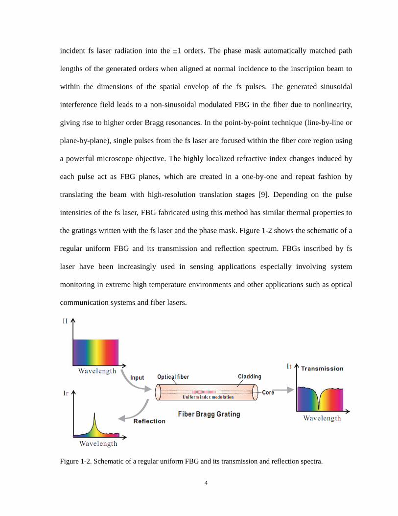
the gratings written with the fs laser and the phase mask. Figure 1-2 shows the schematic of a
regular uniform FBG and its transmission and reflection spectrum. FBGs inscribed by fs
laser have been increasingly used in sensing applications especially involving system
monitoring in extreme high temperature environments and other applications such as optical
communication systems and fiber lasers.
Figure 1-2. Schematic of a regular uniform FBG and its transmission and reflection spectra.
4

As a periodic modulation of the refractive index along a length of optical fiber results in
the FBG which acts as a band-rejection optical filter and passes all wavelengths of light not
in resonance with it, our motivation for fabricating the fiber random grating using the fs laser
micromachining technique arises from the curiosity that what would the optical properties of
a fiber random grating with randomly spaced refractive index modulations on one hand. On
the other hand, it is more strongly desired to design and fabricate a compact fiber-based
random medium to provide random distributed feedback for random fiber lasers as well as to
explore and exploit the advantages and benefits brought to the random laser area by the fiber
random grating.
1.1.2 Random lasers
With the invention of the laser in the late 1950s, a prosperous and continuous development
of novel photonic devices and advanced optical engineering techniques has been on the way,
which has a wide impact across many traditional and cutting-edge sectors of the world
economy. Conventional lasers are mainly comprised of a resonant cavity with a gain medium
for amplification inside. The resonant cavity provides positive feedback to the light trapped
inside and the gain medium amplifies the feedback light. The lasing occurs when the gain in
the cavity overcomes the total loss. Normally the material of the gain medium determines the
scale of the photon amplification and the lasing wavelengths. The resonant cavity introduces
cavity modes to the laser, which define the exact generated lasing frequency and determine
the spatial structure of the output beam.
The initial discovery of random lasing was firstly conducted by Letokhov in 1966, when
he was studying the interstellar radiation and found that the non-resonant feedback would
lead to lasing at the frequency of the maximum gain [10, 11]. After three decades, the term
5
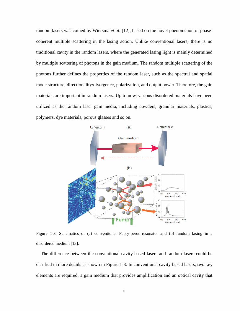
random lasers was coined by Wiersma et al. [12], based on the novel phenomenon of phase-
coherent multiple scattering in the lasing action. Unlike conventional lasers, there is no
traditional cavity in the random lasers, where the generated lasing light is mainly determined
by multiple scattering of photons in the gain medium. The random multiple scattering of the
photons further defines the properties of the random laser, such as the spectral and spatial
mode structure, directionality/divergence, polarization, and output power. Therefore, the gain
materials are important in random lasers. Up to now, various disordered materials have been
utilized as the random laser gain media, including powders, granular materials, plastics,
polymers, dye materials, porous glasses and so on.
Figure 1-3. Schematics of (a) conventional Fabry-perot resonator and (b) random lasing in a
disordered medium [13].
The difference between the conventional cavity-based lasers and random lasers could be
clarified in more details as shown in Figure 1-3. In conventional cavity-based lasers, two key
elements are required: a gain medium that provides amplification and an optical cavity that
6

traps the light inside by creating positive feedback. As shown in Figure 1-3(a), a
conventional Fabry-Perot (FP) resonator consists of a gain medium sandwiched by two
reflecting mirrors. In order to generate lasing, the gain in the cavity should overcome the
total loss of the resonator, i.e. R1R2exp(2GL) should be met. Here R1 and R2 are the reflection
ratios of the two reflectors, G is the gain provided by the gain medium, and L is the cavity
length. In such a cavity, the coherent interference among lights with different round trip
times lead to lasing at longitudinal mode frequencies with vN= Nc/(2Ln), where N is the order
of the longitudinal mode, c is the speed of light in vacuum, n is the refractive index in the
cavity. If no filtering mechanism is employed, multiple longitudinal mode lasing is expected
and radio-frequency inter-mode beatings could be observed by an electrical spectrum
analyzer.
In random lasers as shown in Figure 1-3(b), light no longer travels along multiple round
trip paths determined by the two fixed reflectors as in the conventional laser cavity, but
rather wanders in the disordered gain medium along complicated paths. Two criteria are
usually used to define a random laser: (i) light is multiply scattered in the randomly
disordered gain medium and amplified by the stimulated emission, and (ii) there is a
threshold above which the total gain is larger than the loss. During the multiple-scattering
process, there are two characteristic length scales for photons that are trapped in the random
medium, which could be used to characterize the random lasing behavior. One is the
generation length, which is the average distance a photon travels before generating a second
photon through the stimulated emission. The other one is the mean path length, which is the
distance a photon travels in the gain medium before escaping. When the generation length is
smaller than the mean path length, every photon that travels inside the gain medium will
generate another photon before it leaves the medium, which will trigger a chain reaction and
7

lead to lasing action. Note that stronger scattering will result in longer mean path length and
higher probability for generating more photons through the interaction with the gain medium.
Thus the case when the generation length is equal to the mean path length determines the
threshold for the random lasing. The multiple-scattering process in random lasers defines
spectral and spatial optical modes with a certain frequency and bandwidth and a complex
spatial profile. In some sense, random lasers are mirror-less but not mode-less. In terms of
types of feedback, random lasers could be categorized into two kinds, one with non-resonant
feedback and the other one with resonant feedback. The non-resonant feedback in random
lasers was firstly introduced by Ambartsumyan et al. in 1966 [14, 15]. They replaced one of
the cavity reflectors in the conventional lasers with a highly scattering bulk medium. In this
situation, the phase information of the photons was assumed lost due to numerous random
scattering in the disordered medium. Thus light from different multiple-scattering paths
cannot be coherently superimposed with each. As a result, the laser generation consists of a
large number of broad and overlapping low-Q modes, which prevents the formation of
distinct spatial optical modes. Such a non-resonant feedback imposes no spectral selectivity
on the lasing output and is thought to be frequency independent. The generated random
lasing spectrum is often featured with broad spectral width and centered on the frequency
where the gain is maximum. It has been demonstrated that random lasers with non-resonant
feedback also shows some similar properties as the key features of conventional lasers, such
as spectrum narrowing, existence of the relaxation oscillation, and threshold behavior of the
output lasing power [16, 17]. Different from the non-resonant feedback, random lasers with
resonant feedback were also discovered by H. Cao in 1998, where coherent lasing was
observed using ZnO powder and polycrystalline films [18, 19]. In this case, light after
multiple scatterings can be coherently overlapped, which leads to interference effects in the
8

feedback. Such a resonant feedback contributes to the narrow lasing spikes on top of the gain
profile, whose positions are randomly distributed over the spectrum. After these initial efforts,
research has been focused on investigating and developing random lasers operating in
different gain and scattering mediums. A tremendous number of novel random lasers has
been reported so far, such as random lasers based on direct bandgap semiconductors [20],
dye and polymer based random lasers [17, 21], plasmonic-enhanced random lasers [22], rare-
earth doped powder based random lasers [23], random microchip lasers [24], biological
tissue based random lasers [25] and so on.
Figure 1-4. Schematic of Rayleigh scattering based random fiber laser [26].
However, there are still a number of technical and fundamental issues that make the
utilization of random lasers challenging. Due to the three dimensional disordered materials
and random multiple-scatterings, traditional random lasers often suffer from drawbacks of
low contrast of lasing peaks, high lasing threshold values, lack of directionality, and random
oscillations at multiple wavelengths. To overcome some of these drawbacks, random lasing
occurring in optical fibers have been proposed and investigated intensively. In a single mode
fiber (SMF), light is confined in a transverse direction and propagates as the fundamental
9

transverse mode in the fiber. Consequently, SMF could be regarded as a one-dimensional
waveguide for random fiber lasers and only the longitudinal variations of the waveguide
would impose influence on the lasing dynamics. The intrinsic disorder in the silica fibers
originates from the sub-micron scale inhomogeneity in the refractive index along the fiber
axis due to the fiber manufacturing process. This inhomogeneity induces the well-known
Rayleigh scattering in the optical fiber as shown in Figure 1-4, which is very small and only
corresponds to 5×10⁻⁵ km-1 of the input light. Rayleigh scattering is an elastic scattering
process and in optical fibers it scatters light with random strengths and at random positions
over the fiber length. If external disturbances are isolated from the optical fiber, this
scattering process will remain unchanged in time and the density fluctuations in the fiber
core are regarded to be frozen and static. Despite the small values of the Rayleigh scattering
feedback, random lasing could still be triggered as long as high gain is initiated in the silica
fiber and a long enough fiber is used to provide stronger feedback. The first effort to achieve
random fiber laser using Rayleigh scattering is reported in 2010 [27], where an 83km long
conventional telecom fiber acted as the Raman gain medium and provider of Rayleigh
scattering feedback at the same time. A relative low-threshold, efficient, narrowband
continuous wave (CW) lasing output was realized. Later on, a large number of random fiber
lasers have been proposed and demonstrated by varying the fiber type, fiber based gain
medium, gain mechanism in optical fibers and so on.
Our motivation for linking the fiber random grating and random fiber lasers is based on
the aim for replacing the long optical fiber providing random distributed feedback with a
short counterpart, which would improve the random fiber laser system in terms of laser noise
and compactness. As most of the previously reported random fiber lasers are based on the
Rayleigh distributed feedback from a relatively long fiber length (>1km), the long open
10

cavity formed by the long fiber naturally introduces large numbers of cavity modes to the
laser, which would lead to intensified noise in the performance of the random fiber laser
when external disturbances are not completely eliminated. By shortening the length of the
random distributed feedback fiber and meanwhile enhancing the Rayleigh scattering with the
inscription of random grating, a more compact random fiber laser with mitigated mode
competition and mode hopping is expected. Other aspects concerning the properties of the
random fiber lasers based on fiber random grating such as linewidth characterization,
intensity and frequency noise measurement, lasing threshold, and the applications of the
proposed lasers also give rise to our motivations for this research.
1.1.3 Chaotic semiconductor lasers
Lasing action in semiconductors was firstly reported in 1962. The device used consisted of
a forward-biased GaAs p-n junction. The optical gain was provided by the electron-hole
recombination in the depletion region of the p-n junction and the optical feedback was
provided by the polished facets perpendicular to the junction plane, which forms a resonant
cavity. Later works have developed semiconductor lasers at different wavelengths by
employing p-n junctions of different direct-band-gap semiconductor materials. Up to now,
semiconductor lasers have found numerous applications, including imaging, sensing, fiber-
optic communications and spectroscopy.
Most practical semiconductor lasers operate with a constant output power or pulsing
dynamics. However, it was also discovered that semiconductor lasers are able to emit
chaotically if they are perturbed with increased number of dynamic dimensions. As usually
the dynamics of semiconductor lasers is described using rate equations for the electric field
and carrier inversion, which is a second-order nonlinear system yielding a driven damped
11

nonlinear oscillator, i.e. relaxation oscillations. This feature makes the semiconductor laser
very sensitive to the external optical perturbations. The induced anti-guidance effect detunes
the emission frequency of the semiconductor lasers from the gain spectrum peak, which
results in refractive index variation with carrier density, leading to spectral broadening and
lasing instabilities [28-30].
Many configurations have been proposed to overcome the damped relaxation oscillations
in semiconductor lasers and to generate laser chaos. One of the effective methods is returning
a small fraction of the laser emission in the laser cavity by using external feedback [31]. The
chaotic dynamics of the perturbed semiconductor laser is determined by the competition
between the laser’s intrinsic relaxation oscillation and the introduced external cavity modes.
When the frequency of the external cavity mode is much smaller than that of the intrinsic
relaxation oscillation, such low frequency modulations will induce low frequency power
fluctuation and coherence collapse dynamics [32, 33], which is attributed by the inclusion of
higher dimensions of nonlinearities. It has been demonstrated that feedback provided in
different ways, such as single mirror, double mirrors, phase-conjugate mirror, FP etalon,
diffraction grating, polarizer and so on, is able to disturb the semiconductor lasers with
chaotic output.
Chaotic lasers have been widely applied and utilized in the chaos communications, where
synchronized chaotic lasers are used to perform digital communications and improve
encryption security [34]. Random number generation is one of the important applications of
the chaotic lasers in the chaos communication. Chaotic semiconductor lasers provide ideal
physical source of random bits, which possesses outcome unpredictability and no
dependence on any previous outcome. The currently achieved random bit generation rates
have reached several gigahertz bit per second by directly employing the output of the chaotic
12

semiconductor laser [35] and hundreds of gigahertz bit per second by using signal post-
processing methods, such as derivative calculations of the chaotic signal, multi-bit extraction
[36, 37]. Other applications of chaotic lasers include chaotic optical sensing [38, 39], optical
logic [40], and chaos computing [41].
Our motivation for applying the fiber random grating in the generation of the laser diode
chaotic output is to investigate the dynamics of the semiconductor laser when it is subjected
to the random distributed external feedback, which has never been studied or researched.
Moreover, there are expectations that the random distributed feedback provided by the fiber
random grating can effectively suppress the TDS in the chaotic semiconductor laser output,
which is quite frequently encountered in the chaotic lasers induced by the external feedback.
1.2 Thesis contribution
This thesis has investigated the optical properties of a novel fiber random grating
fabricated by fs laser micromachining technique and extended the applications of the fiber
random grating from optical sensing to random fiber lasers and chaotic semiconductor laser
based random bit generations. Major contributions of this thesis include:
Firstly, we conceived the novel idea of fabricating the fiber random grating using fs laser
micromachining technique and introduced the manufacturing procedures in detail. Initial
investigations revealed that the randomly varying spaced plane-by-plane writing technique
brings novel physical properties to the fiber random grating, such as multiple-interfering
reflection spectrum and induced random birefringence along the sample fiber. Based on the
multiple interference feature of the fiber random grating, a novel multi-parameter fiber-optic
sensor is proposed and demonstrated to realize simultaneous measurement of temperature,
axial strain, and surrounding refractive index thanks to the extended index modification in
13

the fiber cladding layer. A wavelength-division spectral cross-correlation algorithm is
adopted to extract the phase variation induced spectral shift responding to different external
disturbances. Sensitivities of 10.32 pm/°C, 1.24 pm/με, and −1520.6 pm/RIU were achieved
for temperature, axial strain, and surrounding refractive index, respectively. The developed
sensor can be potentially applicable in areas of engineering, biomedical, biological, and
environmental sensing with its robust physical strength and high sensitivities.
Secondly, novel BRFLs are proposed and demonstrated. The first work in this area
proposed a novel BRFL based on a bi-directionally pumping scheme through the SBS in a
10-km-long optical fiber. Theoretical analysis predicts a random fiber FP resonator is built up
through the pump depletion effects of SBS at both ends of the fiber with capability of
narrow-linewidth lasing emission. The linewidth of the BRFL is measured to be ~860Hz,
which can be successfully applied for linewidth characterization beyond 860 Hz of light
source under test. Then the random grating-based FP resonator is introduced to build up
another novel BRFL. Significantly enhanced random feedback from the fiber random grating
overwhelms the Rayleigh backscattering from the standard single mode fiber, leading to
efficient Brillouin gain for the lasing modes and reduced lasing threshold. The intensity and
frequency noises of the proposed random laser are effectively suppressed due to the reduced
resonating modes and mode competition resulting from the random grating-formed filters
compared to those of the Rayleigh feedback resonator in single mode fibers. The linewidth of
the coherent random lasing spike is measured to be ~45.8 Hz using the heterodyne technique.
The proposed narrow-linewidth BRFL will pave the way for applications in high-resolution
spectrometers, coherent light sources, and optical sensing.
Thirdly, novel EDFRLs are designed and demonstrated for optical sensing applications.
The random feedback from the fiber random grating plays an important role in improving the
14

physical properties of the random fiber lasers and exploiting novel applications based on
random fiber lasers. In the fiber random grating based EDFRLs, numerous polarization-
dependent spectral filters are formed in the fiber random grating and they are superimposed
to provide multiple lasing lines with high SNR up to 40dB, which gives an access for a high-
fidelity multiple-static-parameter sensing scheme. The number of sensing parameters can be
controlled by the number of the lasing lines via input polarizations and wavelength shifts of
each peak can be explored for the simultaneous multi-parameter sensing with one sensing
probe. The proposed random laser sensor has achieved simultaneous temperature and axial
strain measurements with maximum errors of 2.3oC and 15.2με, respectively. In addition, the
random grating induced coupling between core and cladding modes can be potentially used
for liquid medical sample sensing in medical diagnostics, biology and remote sensing in
hostile environments. The fiber random grating based EDFRL is also able to detect the
ultrasound waves. With a single mode lasing scenario, this random laser sensor offers linear
and pure temporal responses to the broadband ultrasonic acoustic emission from 20kHz to
0.8MHz. The multiple-interfering reflection spectrum of the random grating provides large
number of steep peak areas over a broad spectral range, which significantly enhances the
sensitivity of the random laser sensor and makes it an ideal sensor in harsh environment with
large temperature or strain variations. The proposed laser sensor offers SNR improvement up
to 20dB and higher sensitivity compared with conventional piezoelectric acoustic sensors. It
is believed that the proposed laser sensor is a truly practical ultrasonic sensor and would find
important applications in many ultrasound-related areas, such as structural health monitoring,
geophysical exploration, material testing, and biomedicine.
Finally, we demonstrate that the distributed feedback from a fiber random grating can
perturb a semiconductor laser into chaotic emission without the TDS. A theoretical model is
15

developed by modifying the Lang-Kobayashi model in order to numerically explore the
chaotic dynamics of the laser diode subjected to the random distributed feedback. It is
predicted that the random distributed feedback is superior to the single reflection feedback in
suppressing the TDS. In experiments, a massive number of feedbacks with randomly varied
time delays induced by a fiber random grating introduce large numbers of external cavity
modes into the semiconductor laser, leading to the high dimension of chaotic dynamics and
thus the concealment of the TDS. The obtained TDS with the maximum suppression is
0.0088, which is the smallest to date. This effective and simple approach is easily applicable in
the concealment of the encryption system parameters and could hence improve the security in
optical chaos based communications.
1.3 Thesis outline
This thesis contains nine chapters and is organized as follows:
Chapter 1 reviews the background of the fs laser micromachining technique and fs laser
fabricated FBG, random lasers, and chaotic semiconductor lasers. Thesis contribution and
outline are also given in this chapter.
Chapter 2 presents the fabrication procedure of the fiber random grating by fs IR laser
micromachining technique and the optical properties of the fiber random grating. A novel
multi-parameter point fiber-optic sensor based on fiber random grating is proposed and
demonstrated to realize simultaneous measurement of temperature, axial strain, and
surrounding refractive index.
Chapter 3 reviews various random fiber lasers employing different gain mechanisms,
including Raman gain, Brillouin gain, and Erbium-doped fiber gain. Different configurations
for random fiber lasers are presented and compared. The properties of random fiber lasers,
16

including linewidth characterization, lasing mode, intensity and frequency noise are
discussed and summarized.
Chapter 4 investigates the physics and presents experimental results of a novel BRFL
based on the bi-directionally pumped SBS in a 10-km-long optical fiber.
Chapter 5 investigates the physics and presents experimental results of a novel BRFL with
the fiber random grating based FP resonator. The linewidth, threshold, intensity and
frequency noise of the proposed random laser are measured and displayed.
Chapter 6 proposes a fiber random grating based EDFRL sensor for multiple static
parameters measurement. The lasing characteristics is investigated and demonstrated through
theoretical modeling and experiments. Simultaneous measurement for temperature and strain
is performed and the measurement error is analyzed and calculated.
Chapter 7 proposes a fiber random grating based EDFRL sensor for ultrasound detection.
By utilizing the multiple-interfering reflection spectrum of the fiber random grating,
ultrasound signals with frequencies from 20kHz to 0.8MHz could be detected with high
sensitivity.
Chapter 8 studies and investigates the suppression of the TDS of the chaotic output of a
semiconductor laser subjected to the random distributed feedback from the fiber random
grating. Theoretical modeling and experimental results are presented, demonstrating the
effectiveness of the fiber random grating feedback for the TDS suppression.
Chapter 9 concludes all the work in this thesis and proposes possible directions for future
research.
17

Chapter 2 Fiber random grating and
its application in fiber-optic sensing
This chapter presents the fabrication and optical properties of fiber random grating using
femtosecond (fs) laser micromachining technique. A novel multi-parameter fiber-optic sensor
based on the fabricated fiber random grating is proposed and demonstrated to realize
simultaneous measurement of temperature, axial strain, and surrounding refractive index. We
proposed a wavelength-division spectral cross-correlation algorithm to extract the phase
variation induced spectral shift responding to different external disturbances. Sensitivities of
10.32 pm/°C, 1.24 pm/με, and −1520.6 pm/RIU were achieved for temperature, axial strain,
and surrounding refractive index, respectively. Section 2.1 gives the background of the
previously reported fiber random gratings. Section 2.2 introduces the fabrication of the novel
fiber random grating. Section 2.3 shows the optical properties of the fiber random grating
through both theoretical modeling and experiments. Section 2.4 describes the optical sensing
application of fiber random grating. Section 2.5 draws the final conclusion.
2.1 Background
There has been a long history of studying the influence of the noise in the fabrication
system on the quality of fabricated fiber Bragg gratings (FBGs). Conventional FBGs are
manufactured by periodically modulating the refractive index of an optical fiber along the
fiber axis. Noise induced in the fabrication process is usually considered an undesirable
factor that could disrupt the periodicity of the refractive index modulation, and thus it makes
18

detrimental impacts on the optical properties of the fabricated FBG. Previously, the influence
of random phase and index errors on FBGs have been studied in [42], where the effects of
the excess crosstalk induced in apodized gratings used in wavelength-division-multiplexing
(WDM) systems and the time delay fluctuations in chirped gratings are analyzed. Other
related studies include the grating reconstruction from noisy reflection data via inverse
scattering method [43, 44]. However, these works mainly focus on elimination of the noise
impacts. It was not shown until recently that the noise could play a positive role in
fabricating fiber gratings either for improving their spectral responses with better filtering
effect or for novel applications in random fiber lasers. Such gratings fabricated with random
phases and refractive indexes as well as wavelength-scale periods are called random FBG.
In 2008, Derevyanko theoretically proposed a method utilizing some specific distributions
of noise in the reflection coefficient inside the bandgap as well as the distribution of time
delays of the grating to realize the flat-top random FBG [45]. The simulation results predict
that the averaged spectrum is flat within the bandgap of the fabricated random FBG and the
sidelobes are significantly suppressed compared to the regular uniform gratings. Later work
further investigated the impacts of different statistics of noise in the refractive index
modification on the properties of the random FBG [46]. Random FBGs with top-hat spectral
response have also been successfully fabricated with noisy modulation in the refractive index
and other pseudo-random designs. Such a top-hat random FBG has important applications in
WDM networks, optical switching, and high power fiber lasers. Another group of random
FBG was proposed by Kashyap in 2009 for providing random distributed feedback for
random fiber lasers, where a long FBG fabrication technique was employed by insertion of a
large number of randomly distributed phase errors in the grating structure [47]. The
fabrication technique was based on a push/pull phase shifting interferometry [48]. As the
19
fiber was held by a vacuum v-groove mount, irregularities in the grating spectrum were
induced by the friction between the fiber and the mount. The fabricated random FBG could
be regarded as a superposition of a large number of short length gratings with different
lengths and random phase shifts between them. The resultant reflection spectrum showed a
combination of a conventional profile of the regular FBG and many random spectral spikes.
The novel random FBG exhibits a typical light localization behavior which is beneficial for
the build-up of random fiber lasers. A continuous work later proposed another alternative
method for fabricating high-quality ultra-long random FBGs [49]. A piezomounted phase
mask placed on a conventional Talbot interferometer was used to generate a moving fringe
pattern. Random phase shifts could be added to the inscription process by applying a random
DC bias on the ramp signal that controls the piezomounted phase mask to be synchronized
with the moving fiber. One-meter long random FBG was obtained by introducing a large
number of random phase shifts following the Poisson distribution, which was then used as a
random coherent feedback medium in a Raman random fiber laser [50].
However, these previously reported random FBGs do not possess truly random spectral
responses. Random FBGs with top-hat reflection spectrum are obviously a perfect spectral
filter for single wavelength, which is not suitable for random fiber laser applications. While
random FBGs proposed by Kashyap, although showing some improvements in the spectral
randomness as multiple resonant spikes are observed on top of the reflection spectrum
envelope, still somehow have a dominant peak envelope at a single wavelength, which could
not be regarded as an ideal random medium for random fiber lasers. To optimize the spectral
randomness of the random FBGs, we will show in the next section that a completely novel
technique and design will be adopted for the fabrication of fiber random gratings.
20

2.2 Fabrication of fiber random grating
The fiber random grating we proposed was fabricated employing the direct writing method,
i.e. plane-by-plane writing technique. The plane-by-plane writing technique uses single
pulses from the fs laser that are focused within the core region of the fiber using a powerful
microscope objective. Each pulse makes highly localized changes to the refractive index that
act as FBG planes. Planes are created sequentially in a step and repeat fashion by translating
the beam using high-resolution mechanical translation stages. Depending on the pulse
intensities, the resulting grating structures could be fabricated with thermal stability either
similar to Type-I grating or Type-II grating.
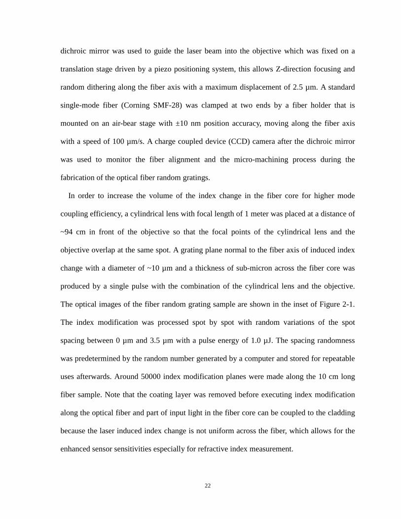
Figure 2-1. Experimental setup of the plane-by-plane fs laser micromachining system with
microscopic images of the fiber random grating sample.
For the inscription of the fiber random gratings, a fs Ti:sapphire regenerative amplifier
(Spitfire, Coherent) operating at a wavelength of 800 nm with a repetition rate of 100 Hz and
a pulse duration of 80 fs was used in the experiments as shown schematically in Figure 2-1.
A beam reducer consisting of one plano-convex lens and one plano-concave lens was used to
reduce the beam width to match the open aperture of the objective (50×/0.6, Nikon). The
21
dichroic mirror was used to guide the laser beam into the objective which was fixed on a
translation stage driven by a piezo positioning system, this allows Z-direction focusing and
random dithering along the fiber axis with a maximum displacement of 2.5 µm. A standard
single-mode fiber (Corning SMF-28) was clamped at two ends by a fiber holder that is
mounted on an air-bear stage with ±10 nm position accuracy, moving along the fiber axis
with a speed of 100 µm/s. A charge coupled device (CCD) camera after the dichroic mirror
was used to monitor the fiber alignment and the micro-machining process during the
fabrication of the optical fiber random gratings.
In order to increase the volume of the index change in the fiber core for higher mode
coupling efficiency, a cylindrical lens with focal length of 1 meter was placed at a distance of
~94 cm in front of the objective so that the focal points of the cylindrical lens and the
objective overlap at the same spot. A grating plane normal to the fiber axis of induced index
change with a diameter of ~10 µm and a thickness of sub-micron across the fiber core was
produced by a single pulse with the combination of the cylindrical lens and the objective.
The optical images of the fiber random grating sample are shown in the inset of Figure 2-1.
The index modification was processed spot by spot with random variations of the spot
spacing between 0 µm and 3.5 µm with a pulse energy of 1.0 µJ. The spacing randomness
was predetermined by the random number generated by a computer and stored for repeatable
uses afterwards. Around 50000 index modification planes were made along the 10 cm long
fiber sample. Note that the coating layer was removed before executing index modification
along the optical fiber and part of input light in the fiber core can be coupled to the cladding
because the laser induced index change is not uniform across the fiber, which allows for the
enhanced sensor sensitivities especially for refractive index measurement.
22

2.3 Optical properties of fiber random grating
To investigate the optical properties of the fiber random grating, we built up the
experimental setup for monitoring the fiber random grating spectra as shown in Figure 2-2. A
broadband light source (NKT Photonics) ranging from 1400nm to 1600nm was used and
launched to the input port 1 of the circulator. The optical fiber random grating was mounted
on two micro-stages. One end of the random grating was connected to port 2 of the circulator,
while the other end was cut with non-perpendicular cleave. The reflected light spectrum
comprising 50000 data points was collected by an Optical Spectrum Analyzer (OSA) with a
wavelength resolution of 20 pm through port 3 of the circulator. The inset spectrum shows an
example of the reflection (blue) and transmission (red) spectra of the random grating. The
incident light would be divided into two parts when refracted by the random grating planes,
one of which is coupled into the cladding region being transmitted or reflected in the form of
cladding modes due to the non-uniform index modification induced by fs laser across the
fiber while the other one remains being transmitted or reflected as core mode. It is illustrated
that only a small proportion of the incident light is reflected backward at the spots with
localized changes in the refractive indices. High attenuation in transmission spectrum is due
to the significant refraction loss and absorption loss at the non-uniform index modification
regions. It is also noted that an interference pattern is hardly observed in the transmission
spectrum as the energies of the transmitted cladding modes are relatively small compared to
that of the transmitted core mode, leading to a minimum visibility in the transmitted
interference spectrum.
23
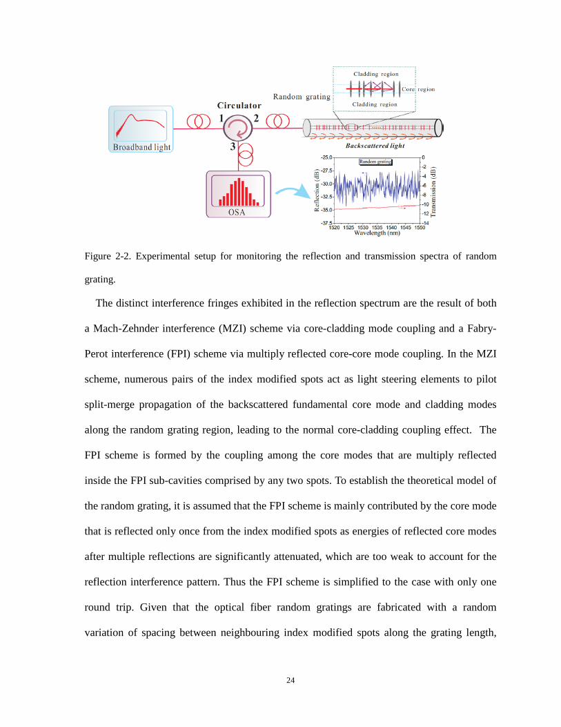
Figure 2-2. Experimental setup for monitoring the reflection and transmission spectra of random
grating.
The distinct interference fringes exhibited in the reflection spectrum are the result of both
a Mach-Zehnder interference (MZI) scheme via core-cladding mode coupling and a Fabry-
Perot interference (FPI) scheme via multiply reflected core-core mode coupling. In the MZI
scheme, numerous pairs of the index modified spots act as light steering elements to pilot
split-merge propagation of the backscattered fundamental core mode and cladding modes
along the random grating region, leading to the normal core-cladding coupling effect. The
FPI scheme is formed by the coupling among the core modes that are multiply reflected
inside the FPI sub-cavities comprised by any two spots. To establish the theoretical model of
the random grating, it is assumed that the FPI scheme is mainly contributed by the core mode
that is reflected only once from the index modified spots as energies of reflected core modes
after multiple reflections are significantly attenuated, which are too weak to account for the
reflection interference pattern. Thus the FPI scheme is simplified to the case with only one
round trip. Given that the optical fiber random gratings are fabricated with a random
variation of spacing between neighbouring index modified spots along the grating length,
24
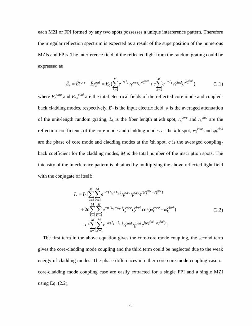
each MZI or FPI formed by any two spots possesses a unique interference pattern. Therefore
the irregular reflection spectrum is expected as a result of the superposition of the numerous
MZIs and FPIs. The interference field of the reflected light from the random grating could be
expressed as
, 01 1
( )core clad
k k k kM M
L i L icore clad core cladr r r c k k
k kE E E E e r e c e r eα ϕ α ϕ− −
= == + = +∑ ∑
(2.1)
where Ercore and Er,c
clad are the total electrical fields of the reflected core mode and coupled-
back cladding modes, respectively, E0 is the input electric field, α is the averaged attenuation
of the unit-length random grating, Lk is the fiber length at kth spot, rkcore and rk
clad are the
reflection coefficients of the core mode and cladding modes at the kth spot, φkcore and φk
clad
are the phase of core mode and cladding modes at the kth spot, c is the averaged coupling-
back coefficient for the cladding modes, M is the total number of the inscription spots. The
intensity of the interference pattern is obtained by multiplying the above reflected light field
with the conjugate of itself:
( ) ( )0
1 1
( )
1 1
( ) ( )2
1 1
[
2 cos( )
]
core corek k k k
k k
clad cladk k k k
M ML L icore core
r k kk k
M ML L core clad core clad
k k k kk kM M
L L iclad cladk k
k k
I I e r r e
c e r r
c e r r e
α ϕ ϕ
α
α ϕ ϕ
ϕ ϕ
′ ′
′
′ ′
− + −′
= =′
− +′ ′
= =′
− + −′
= =′
=
+ −
+
∑∑
∑∑
∑∑
(2.2)
The first term in the above equation gives the core-core mode coupling, the second term
gives the core-cladding mode coupling and the third term could be neglected due to the weak
energy of cladding modes. The phase differences in either core-core mode coupling case or
core-cladding mode coupling case are easily extracted for a single FPI and a single MZI
using Eq. (2.2),
25

4=core core core core corel nπϕ ϕ ϕ
λ−′∆ − =′ (2.3)
2= ( )core corecore clad clad cladl n nπϕ ϕ ϕ
λ−∆ − = − (2.4)
where l’ and l are the interferometer lengths in the core-core mode coupling scheme and
core-cladding mode coupling scheme, respectively, ncore and nclad are the effective refractive
indices for the core mode and cladding modes, respectively. It is noted that the above
equations do not distinguish different cladding modes as in fact several cladding modes
could be excited to share the energy of light which is coupled into the cladding region from
core mode.
2.4 Comparison with regular FBG and random FBG
Figure 2-3. Reflection spectra of (a) regular FBG, (b) random FBG, and (c) fiber random grating.
The reflection spectrum of the proposed fiber random grating is compared with those of a
regular FBG and a random FBG. In a regular FBG, the index modulation along the fiber core
takes the form of a phase and amplitude-modulated periodic waveform:
02( ) ( )[1 cos( ( ))]zn z n z m zπδ δ φ= + +Λ
(2.5)
Where δn is the index perturbation, z is the position along the fiber, Λ is the grating period,
ϕ(z) is the phase term, m is the contrast of the modulation determined by the visibility of the
writing laser fringe pattern. The grating filter characteristics can be analyzed through the
coupled-mode theory. The simplest form of this analysis leads to a single Ricatti differential
26

equation for a modified local reflectivity ρ(z), which could be easily integrated by standard
numerical methods. The reflectivity of the grating at the line center is expressed as
2 2
2 2 2sinh ( )= =
ˆcosh ( )κ αρρ
κ α σ∗
−LR
L (2.6)
with
2 2ˆ= -ˆ= +
=
2
2
α κ σσ δ σ
πκ δλπ πδλπσ δλ
= −Λ
=
m n
n
n
(2.7)
The above equations give the analytical solution of the reflection spectrum of a regular FBG
and the corresponding reflection spectrum is shown in Figure 2-3(a). The maximum
reflectivity of the FBG increases with the total grating length L and the index modification
depth δn. The bandwidth decreases with the grating length and increases with the index
modification depth. A Bragg grating is able to couple different modes in reflection and
transmission direction as long as two conditions are satisfied: 1) phase matching condition
and 2) sufficient mode overlapping condition. The phase matching condition is given by
'eff effn nλ− =
Λ (2.8)
where neff is the effective refractive index of the incident fundamental core mode; n’eff is the
effective refractive index of grating-coupled reflected (which is a negative value) or
transmitted mode. Following this phase matching condition, with a sufficient fine pitch that
satisfies the Bragg condition:
2B effnλ = Λ (2.9)
27

the forward-propagating bound-mode will be reflected as backward-propagating bound-
mode with the same order. It should be noted that other modes at shorter wavelengths could
also be excited from the incident fundamental mode, most of which however will be
reflected or absorbed, or radiated away from the fiber. Cladding modes can be excited
interacting with the forward-propagating fundamental core mode, leading to a series of
transmission dips in the spectrum at wavelengths shorter than the Bragg wavelength.
In the random FBG, phase errors are introduced randomly and continuously along the
grating profile by the friction between the fiber and the mount when the fiber is pulled for
grating inscription. Note that the introduced phase noises in the phase term of Eq. (2.5) are
small and the grating periods are only slightly modified, leading to quasi-periodical index
modulations. Thus the random FBG could be regarded as a succession of a great number of
short length gratings of slightly different lengths and small random phase shifts between
them. The reflection spectrum of this random FBG is shown in Figure 2-3(b), where dense
small ripples are superimposed with a typical general FBG reflection spectrum. The general
envelope of the reflection spectrum originates from the quasi-periodical index modulations,
which still constitute an FBG structure having similar spectral characteristics as the regular
FBGs. The small ripples arise from the light coupling among the large number of short sub-
gratings with different spacing, which forms many random Fabry-Perot etalons. Due to the
large number of the grating pairs, the collective reflection spectrum loses the individual
Fabry-Perot characteristic and shows noisy interference patterns.
The case in the proposed fiber random grating is completely different from the above two
cases as shown in Figure 2-3(c), where no periodicity in the index modulation is maintained.
Every index modification plane in the fiber random grating is inscribed independently
without using a phase mask, which eliminates the phase correlation between the neighboring
28

planes. Moreover, the plane spacing is randomly controlled by dithering the objective lens
used for focusing the fs laser pulse. The index modification depth is also different with
planes, as one plane is made by using a single laser pulse, and the laser power varies for each
individual pulse, which is opposed to the case where the index modification discrepancy is
reduced by using multiple laser pulses for inscription at one region in the fabrication of FBG
or random FBG. Consequently, such a fiber random grating with random periods and random
index modulations loses the general spectral characteristic of FBG and displays a noisy
multiple-interference reflection spectrum resulting from the superposition of many low-
finesse FPIs and MZIs.
2.5 Fiber random grating based multi-parameter sensor
Optical fiber based sensors have received a great deal of attention over the past several
decades for increased sensitivity over existing techniques, geometric versatility, immunity to
harsh environments, and inherent compatibility with optical fiber communication systems. In
particular, multi-parameter optical fiber sensors that monitor physical, chemical, and
biological parameters are of relevant importance in numerous areas including structural
health monitoring, environmental pollution control, biomedical applications and so on [51-
53]. The measurands of temperature, axial strain and surrounding refractive index are among
the most important parameters in the above applications however they usually exert crosstalk
effects on the response of sensors making it difficult to discriminate the individual
measurand. Thus, it is essential to investigate these parameters simultaneously in order to
eliminate the dependence of one parameter upon another [54-56]. Discrimination between
temperature and surrounding refractive index has been published in earlier works including
using a slanted multimode FBG [57], a tapered single mode fiber based Mach-Zehnder
29

interferometer (MZI) [58], a cascaded optical fiber device of long period grating (LPG) and
photonic crystal fiber modal interferometer [59], a surface LPG inscribed in a D-shaped
photonic crystal fiber [60], and a tapered bend-insensitive fiber interferometer [61] etc. To
make a step forward, simultaneous three parameter sensing, especially the measurement of
temperature, axial strain, and surrounding refractive index has also been reported using an
etched-core FBG [62], a tilted FBG [63], polymer-coated FBGs [64], and a cascaded fiber
long period and Bragg gratings [65]. However, these FBG or LPG based devices using either
phase mask or etching/coating techniques and requiring critical alignment and vibration
control make themselves more complex and costly. Our group also presented a work using
tapered bend-insensitive fiber for the discrimination of the three parameters [66]. However,
the fragile tapered structure deteriorates the physical strength and durability of the sensing
device and makes it vulnerable to the external physical disturbances. In this work, a novel
random grating fiber-optic sensor is proposed and fabricated for multi-parameter
discrimination measurement based on a wavelength-division cross-correlation method.
Temperature, axial strain, and refractive index are calibrated by monitoring the linear peak
wavelength shift in different wavelength regions. A sensor character matrix composed of
different rates of wavelength shifts provides the access for the simultaneous measurements
for all three parameters.
30

Figure 2-4. Correlation analysis flow chart for simulated reflection spectra.
Prior to the experiments, simulations of the influence of the measurands on the fiber
random grating spectrum were conducted. The measurands, such as temperature, axial strain,
or surrounding refractive index variations may cause changes in the interferometer length
and effective refractive indices of the core mode and cladding modes in both the core-core
mode coupling and core-cladding mode coupling of the FPIs and the MZIs in the fiber
random grating. According to Eq. (2.3) and (2.4), such changes will accordingly result in a
phase shift that leads to a spectral shift in the corresponding reflection spectrum as compared
to the case without disturbances. A linear peak wavelength shift response could be found for
any specific MZI or FPI so that the superimposed spectral shift from all of the MZIs and
FPIs along the random grating sensor is expected to be linear as well. However, it is
impossible to observe the spectral responses from the entire random grating length by
conventional peak wavelength inspection methods typically used in FBG or LPG sensors.
Thus the spectrum correlation analysis is instead employed to extract the spectral shift
information, and the flow chart is shown in Figure 2-4. Two simulated reflection spectra
spreading over a 200 nm range are presented, one as a reference and the other with an
31
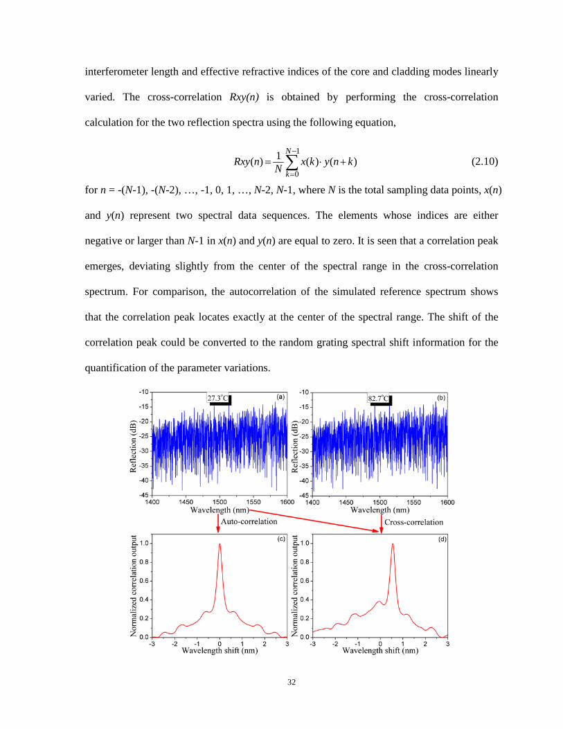
interferometer length and effective refractive indices of the core and cladding modes linearly
varied. The cross-correlation Rxy(n) is obtained by performing the cross-correlation
calculation for the two reflection spectra using the following equation,
1
0
1( ) ( ) ( )N
kRxy n x k y n kN
−
== ⋅ +∑ (2.10)
for n = -(N-1), -(N-2), …, -1, 0, 1, …, N-2, N-1, where N is the total sampling data points, x(n)
and y(n) represent two spectral data sequences. The elements whose indices are either
negative or larger than N-1 in x(n) and y(n) are equal to zero. It is seen that a correlation peak
emerges, deviating slightly from the center of the spectral range in the cross-correlation
spectrum. For comparison, the autocorrelation of the simulated reference spectrum shows
that the correlation peak locates exactly at the center of the spectral range. The shift of the
correlation peak could be converted to the random grating spectral shift information for the
quantification of the parameter variations.
32

Figure 2-5. Measured reflection spectra of the random grating at reference temperature (a) and
changed temperature (b); (c) Auto-correlation spectrum of (a); (d) Cross-correlation spectrum of (a)
and (b).
In experiments, temperature measurements were conducted by placing the random grating
sensor into an oven with a temperature increase step of around 5 oC. Reflection spectra at
each temperature was recorded when the temperature inside the oven remained stable. To
characterize the strain sensitivity of the random grating sensor, the two ends of the sensor
were anchored horizontally between a motorized translational stage and a stationary stage
using super glue. The system is capable of stretching the sensor longitudinally by
manipulating the motorized stage along the axis of the random grating sensor with a
sequential strain step of 100 µɛ. The immersion liquids used in the refractive index
measurements were glycerol solutions at different concentrations. The percent by weight of
glycerol in these solutions could be utilized to determine the solution refractive index, which
provides a refractive index range from 1.332 to 1.384. The recorded reflection spectra of the
fiber random grating under different environmental condition would be processed by using
the spectral correlation method following the flow chart as shown in Figure 2-4. For example,
two reflection spectra that one at 27.3 oC and the other one at 82.7 oC, are shown in Figure 2-
5(a) and (b). The auto-correlation and cross-correlation calculations were performed
respectively, as illustrated in Figure 2-5(c) and (d). Cross-correlation peak wavelength shift
in Figure 2-5(d) demonstrates that the temperature variation indeed exerts an impact on the
reflection spectrum of the sensor and is in accordance with the simulation outcome.
To simultaneously measure the temperature, axial strain, and refractive index using the
random grating sensor, a wavelength-division cross-correlation method is employed to
extract the responses of the random grating sensor to each of the environmental parameters
33

investigated in the experiment as shown in Figure 2-6(a). It is based on the fact that the
spectral response is highly dependent on the dispersion effects of the effective refractive
indices of the core mode and cladding modes when the broadband light source is employed.
The mode field cross-sectional intensity distributions of both core mode and cladding modes
vary with the input light wavelength and are impacted by the external disturbances with
different extents at different wavelengths. Thus the effective refractive indices of core mode
and cladding modes at different wavelength regions vary with different levels, leading to
distinct phase changes in Eq. (2.3) and Eq. (2.4) and different resultant spectral shifts. The
reference reflection spectrum of the random grating at 27.3 oC and with zero strain was
recorded with a spectral range from 1400 nm to 1600 nm. On the one hand, the separation
between the selected wavelength sub-regions is required to be large enough to lead to a sharp
distinction in wavelength shift related sensitivities for different spectral sub-regions. On the
other hand, a wavelength region with a wide spectral range is preferred to ensure better
sensing resolution owing to the increased data points used for cross-correlation. Given the
limited spectral range and finite data points a broadband light source could provide, as well
as the number of desired measurands, the appropriate selection of wavelength sub-regions is
critical to multi-parameter sensing with discrimination capabilities. The whole spectrum is
then divided into three subsections, 1400 nm-1450 nm (short-wavelength), 1475 nm-1525
nm (middle-wavelength) and 1550 nm-1600 nm (long-wavelength), each of which covers 50
nm wide range. The same division is applied to the following reflection spectra measured
with varied temperature, axial strain, and surrounding refractive index. The cross-correlation
algorithm is performed in each of the corresponding spectrum subsections between the
reference reflection spectrum and the measured one with changed parameters. Due to the
wavelength dependent response of the random grating sensor, correlation calculations using
34

different spectrum subsections would result in distinct responses of central peak shift in the
cross-correlation outcome spectra.
Figure 2-6. (a) Three spectrum subsections selected in the reflection spectrum of fiber-optic random
grating; cross-correlation peak wavelength shift calibration results for (b) temperature, (c) strain, and
(d) refractive index.
Figure 2-6(b)(c)(d) present the cross-correlation peak wavelength shift based calibration
plots for each of the three sensing parameters. The temperature measurement results yielded
the cross-correlation peak wavelength shift related temperature coefficients of 9.12 pm/oC,
9.78 pm/oC, and 10.32 pm/oC for the short-wavelength, middle-wavelength and long-
wavelength subsections, respectively, as shown in Figure 2-6(b). Then the spectral shift
related axial strain coefficients for the three subsections are 1.10 pm/µɛ, 1.17 pm/µɛ, and
35

1.24 pm/µɛ, respectively, and are plotted in Figure 2-6(c). The spectral shift related refractive
index coefficients are -1129.2 pm/RIU, -1369.7 pm/RIU, and -1520.6 pm/RIU for the three
subsections, respectively, as shown in Figure 2-6(d). The cross-correlation results in the three
spectral ranges exhibit distinctive dependences in temperature, axial strain and refractive
index, and thus enable the multi-parameter sensing application.
The temperature, strain and refractive index coefficients calibrated above give an access to
construct a character matrix of the proposed random grating sensor, which could facilitate the
discrimination among the temperature, the axial strain and the refractive index, achieving
simultaneous multi-parameter measurements. Defining the cross-correlation peak
wavelength shift related temperature, axial strain and refractive index coefficients of the ith
subsection of the whole spectrum range respectively as CTi, Cε
i, and CRIi, the spectral shift
related character matrix MT,ε,RI is obtained to retrieve the temperature, axial strain and
refractive index information as follows:
1 1 1 1
2 2 2 2, ,
3 3 33,
c T RI
c T RI T RI
c T RI
C C CT TM C C C
RI RIC C C
ε
εε
ε
λλ ε ελ
∆ ∆ ∆∆ = ∆ = ∆
∆ ∆∆
(2.11)
where Δλci are the cross-correlation peak wavelength shifts associated with the ith subsection
of spectral range, and ΔT, Δε, and ΔRI are the temperature, axial strain and refractive index
changes. Error analysis for the simultaneous multi-parameter measurements is given by [67]:
1'
, , 2
3,
cT RI
c
c
T M
RI
εδλδ
δε δλδ δλ
=∆ (2.12)
where δT, δε, and δRI denote the errors of temperature, axial strain, and refractive index,
respectively, Δ is the determinant of MT,ε,RI, M’T,ε,RI is the adjugate matrix and δλci are the
errors in cross-correlation peak wavelength shift associated with the ith wavelength
36

subsection. The maximum errors of temperature measurements are 0.16 pm/oC, 0.16 pm/oC,
and 0.12 pm/oC, and the axial strain measurement errors are 0.01 pm/µɛ, 0.02 pm/µɛ, and
0.02 pm/µɛ, and the refractive index measurement errors are 59.0 pm/RIU, 39.7 pm/RIU, and
65.8 pm/RIU, for the three subsections respectively.
2.6 Conclusion
In conclusion, a novel sensor based on the fs laser fabricated random gratings in SMF has
been proposed to realize the discrimination of temperature, axial strain and refractive index
by monitoring the cross-correlation peak wavelength shift in different spectral ranges. The
spectral shift induced by the aggregated responses of numerous MZIs and FPIs integrated in
the random grating to different measurands is inspected by the spectrum correlation method.
The significant wavelength-dependent spectral shifts in the cross-correlation algorithm
provide an excellent opportunity for simultaneous three and even more parameter
measurements. The developed sensor can be potentially applicable in areas of engineering,
biomedical, biological, and environmental sensing with its robust physical strength and high
sensitivities.
37

Chapter 3 Introduction of random
fiber lasers
This chapter presents comprehensive introduction of the current state-of-art development
of random fiber lasers. Different random fiber lasers are categorized and reviewed. The
lasing feature and properties, linewidth characterization, laser noise measurement, and
important applications of random fiber laser are described and summarized, respectively.
Section 3.1 categorizes different random feedback mechanisms in optical fibers. Section 3.2
studies random fiber lasers based on various gain mechanisms. Section 3.3 introduces lasing
characteristics and mode selection in random fiber lasers as well as linewidth
characterization technique for random fiber lasers. Section 3.4 describes intensity noise
measurement technique for random fiber lasers. Section 3.5 introduces frequency noise
measurement technique for random fiber lasers. Section 3.6 summarizes important
applications of random fiber lasers.
3.1 Random feedback mechanisms in optical fibers
As been discussed in Chapter 1, traditional random lasers are realized by pumping and
utilizing the disordered structures of 3D materials and media, such as powders, polymers,
dye material, porous glasses and so on. However, the control of the laser output performance
in these 3D random lasers is challenging and the lasing efficiency is low. One effective way
to overcome these problems of 3D random lasers is to use lower-dimension random systems.
Optical fibers, being a typical one-dimension waveguide, draw the first attention to make
38

low-dimension random lasers come true. An initial work demonstrated pulsed random lasing
in a few-millimeter-long photonic crystal fiber with hollow core filled with random material
consisting of Rhodamine 6G dye solution with TiO2 particles [68]. This pioneering work,
however, lacks the advantages of simplicity and practicability. It was soon realized that the
optical fiber itself is able to act as gain and scattering medium at the same time, which
significantly improves the directionality of random lasing and lasing efficiency. The first
work realizing random fiber laser was proposed in 2010 by S.K. Turitsyn [27], where a stable
lasing at 1550nm was demonstrated in a conventional telecom optical fiber with Raman gain
distributed along an 83-km long span. By pumping the long telecom fiber, stimulated Raman
scattering (SRS) was triggered to provide gain in the open cavity. The random
inhomogeneity of the refractive index along the fiber results in numerous scattering centers
that randomly reflect incoming light waves back, providing random distributed feedback.
Following this work, various gain mechanisms and random feedback mechanisms in optical
fibers have been investigated and employed to achieve random fiber lasers. The following
sections will describe the physical fundamentals of the feedback mechanisms in optical
fibers and introduce various enhanced feedbacks by using different techniques.
3.1.1 Intrinsic Rayleigh scattering
Rayleigh scattering is the elastic scattering of light or other electromagnetic radiation by
particles much smaller than the wavelength of the radiation. The amplitude of light scattered
from within any transparent dielectric is inversely related to its wavelength. The wavelength
dependence is characteristic of the dipole scattering. The electric dipole in the dielectric is
oscillating in time, which can be considered as a harmonically oscillating electric dipole with
angular frequency ω and a dipole moment p0 along the z-direction of the form
39
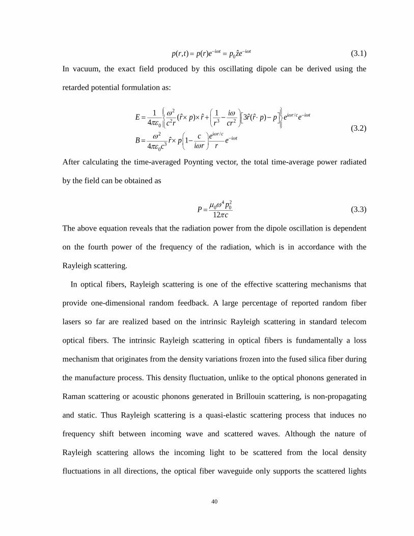
0 ˆ( , ) ( ) ω ω− −= =i t i tp r t p r e p ze (3.1)
In vacuum, the exact field produced by this oscillating dipole can be derived using the
retarded potential formulation as:
2/
2 3 202 /
30
1 1ˆ ˆ ˆ ˆ( ) 3 ( )4
ˆ 14
ω ω
ωω
ω ωπε
ωωπε
−
−
= × × + − ⋅ −
= × −
i r c i t
i r ci t
iE r p r r r p p e ec r r cr
c eB r p ei r rc
(3.2)
After calculating the time-averaged Poynting vector, the total time-average power radiated
by the field can be obtained as
4 20 012µ ω
π=
pP c (3.3)
The above equation reveals that the radiation power from the dipole oscillation is dependent
on the fourth power of the frequency of the radiation, which is in accordance with the
Rayleigh scattering.
In optical fibers, Rayleigh scattering is one of the effective scattering mechanisms that
provide one-dimensional random feedback. A large percentage of reported random fiber
lasers so far are realized based on the intrinsic Rayleigh scattering in standard telecom
optical fibers. The intrinsic Rayleigh scattering in optical fibers is fundamentally a loss
mechanism that originates from the density variations frozen into the fused silica fiber during
the manufacture process. This density fluctuation, unlike to the optical phonons generated in
Raman scattering or acoustic phonons generated in Brillouin scattering, is non-propagating
and static. Thus Rayleigh scattering is a quasi-elastic scattering process that induces no
frequency shift between incoming wave and scattered waves. Although the nature of
Rayleigh scattering allows the incoming light to be scattered from the local density
fluctuations in all directions, the optical fiber waveguide only supports the scattered lights
40

that can be totally reflected counter-propagating respect to the incoming light. The Rayleigh
scattering coefficient varies with the wavelength of the light wave and is dominant at short
wavelengths:
4λα = R
RC
(3.4)
where CR is in the range 0.7-0.9dB/(km-μm4) depending on the constituents of the fiber core.
In the standard telecommunication fiber, the Rayleigh scattering has weak reflection
coefficient r≈ 7.3×10⁻⁸/m along the whole fiber. However, the one-dimensional waveguide
structure of optical fibers can facilitate the accumulative effect of backscattered photons in
spite of such small r.
In standard telecom SMFs, Rayleigh backscattered light can be modeled as a collection of
lights reflected from a sequence of scattering centers. These scattering centers can be seen as
multiple reflectors with weak reflectivity. The fiber can be divided into N small sections and
the length for each section is ΔL=L/N. Each section has one scattering center, which is
randomly located within the section with uniform distribution and assumed to have random
varying reflection coefficients. So when an input light with a coherence length covering the
fiber length L, the electric field of Rayleigh backscattered light can be written as:
01
4exp( 2 ) exp( )πα
λ== − −∑
Nk
R k kk
nLE E L r i (3.5)
where α is the attenuation coefficient of the optical fiber, Lk is the length of the kth scattering
center of the fiber, rk is the reflection coefficient of the kth scattering center. Note that this is
a simplified model for the intrinsic Rayleigh scattering in fiber and its accuracy depends on
the density of the scattering centers set along the fiber. In reality, these scattering centers are
densely distributed along the fiber length and their spacing is so small that dense resonant
41
modes would be present when Rayleigh scattering is used as feedback in random fiber lasers.
In this case, the large number of resonant modes with extremely small free spectral range
would induce strong mode competition and mode hopping effect in the lasing system, which
can further be intensified by external disturbances such as temperature variation and
vibrations in the surrounding environment. As a result, the relative intensity noise of the
Rayleigh scattering based random fiber lasers is relatively high although single-mode
operation can be achieved.
It was also found that the Raleigh backscattered light has similar spectral properties with
the input light. By measuring the frequency information of the Rayleigh backscattering light,
the linewidth of input light source can be recovered. The mean reflected light intensity is
independent of the source light coherence, while its variance is influenced by the input light
polarization states [69]. In low-birefringence fibers, like standard SMF, the state of
polarization of the incoming light is preserved in Rayleigh backscattering light [70], which is
beneficial for the polarization matching induced lasing efficiency improvement.
3.1.2 Enhanced Rayleigh scattering
Due to the weakness and accumulation nature of the intrinsic Rayleigh scattering in the
standard telecom SMFs, long fiber length is usually required for random fiber lasers based on
the intrinsic Rayleigh scattering to provide enough feedback strength and increase lasing
efficiency. An effective way is to use optical fibers that have higher loss than the standard
SMF, which is able to provide enhanced Rayleigh backscattering and thus decrease the
required fiber length. For example, a 300-m SMF with high Rayleigh loss (~17dB/km) was
utilized in a single-end Brillouin random fiber laser (BRFL) proposed in [71]. In a later work,
a novel non-uniform fiber was employed with enhanced Rayleigh feedback to achieve a
42

tunable Erbium-doped fiber random laser (EDFRL) with a 3dB linewidth of less than 2kHz
[72]. The non-uniform fiber was fabricated with the mode field diameter from 5μm at one
end to 7μm at the other end and consequently with a stronger refractive index inhomogeneity
along the fiber axis [73]. It was demonstrated that the Rayleigh scattering coefficient is
enhanced to ~-34dB/km, which is 2 orders higher than standard telecom SMFs. Another
alternative with enhanced Rayleigh scattering is the polarization-maintaining fiber (PMF).
The two-dimensional stress from Baron-doped-silica rods in the fiber introduces additional
transverse non-uniformity into fiber core to increase the Rayleigh scattering coefficient.
However, compared with the high-loss Rayleigh fiber and non-uniform fiber, the
improvement of Rayleigh scattering strength in PMF is still limited.
It has to be noted that although the above-mentioned optical fibers somehow show
enhanced Rayleigh scattering effect due to the increased structural non-uniformity, long fiber
length is still required when they are applied in random fiber lasers, which could introduce a
large density of random modes with strong mode competitions. In addition, long Rayleigh
fibers would be more sensitive to the external disturbances, which makes the laser cavity
unstable and intensifies the mode-hopping effects. Therefore, a more compact fiber structure
with uncompromised feedback strength is highly preferred. Various modification techniques
have been implemented in fibers to enhance the Rayleigh scattering. One typical method is to
inscribe random grating along the optical fiber core regions. An early work inscribed a series
of FBGs along an erbium-doped SMF [74]. FBGs with same index modulation periods were
randomly spaced with separations within 4.2-5.8mm. In another work, a random FBG with
randomly distributed phase shifts was fabricated along one meter long fiber [50]. A ramp
signal was applied to the piezomounted phase mask, to which a DC bias was applied during
the writing process to introduce random phase shifts to the grating. The resultant random
43
FBG has a quasi-periodic index modulation and much higher reflection strength, which
eliminate the needs of tens of kilometer long fibers for Raman random fiber lasers. CO2 laser
has also been used to inscribe random gratings along SMFs. The CO2 laser operates at
wavelength of 10.6μm that overlaps with an OH absorption band in fused silica, which leads
to a quick thermal response to a sharp temperature rise in the fiber. The refractive index of
the irradiated points was modulated through the localized residual thermal stress induced by
the thermal gradients. 100 randomly spaced refractive index modulation regions over 10 cm
SMF were fabricated with significant enhancement in Rayleigh scattering [75]. Other
methods to make compact and enhanced Rayleigh feedback fiber structures include making a
series of abrupt tapers along the SMF using stretching stages and oxyhydrogen flame. 21
tapers with taper length of 2cm and waist diameter of 112.09μm were made along a 110m
SMF in [76].
3.2 Random fiber lasers with different gain mechanisms
Optical gain is another key factor that builds up a laser. Different gain mechanisms in
optical fibers have been employed to achieve random fiber lasers. Thanks to the compact
one-dimensional waveguide structure in optical fibers, these nonlinear gain processes usually
possess high efficiency and amplification magnitude, which is crucial to compensate the high
loss induced by the open cavities in random fiber lasers. The following sections will describe
the physical fundamentals of common gain mechanisms in optical fibers and random fiber
lasers that have been reported based on these gains in details.
3.2.1 Raman random fiber laser
Stimulated Raman scattering (SRS) is an important nonlinear process occurring in optical
44

fibers, which could be utilized to realize broadband Raman amplifiers and tunable Raman
lasers. In telecommunication systems, it is usually negatively regarded as one factor that
severely limits the performance of multichannel lightwave systems by transferring energy
from one channel to the neighboring channels. The Raman effect was first discovered by
Raman in 1928 in the form of spontaneous Raman scattering. This process can transfer part
of power from one optical field to another field with a frequency downshift that is
determined by the vibrational modes of the molecular medium. The incident light acts as
pump light and the generated frequency-downshifted radiation is called Stokes light. Later it
was found that with intense pump power, SRS can occur inside the medium with a nonlinear
behavior in which most energy of the pump light is transferred to the Stokes light. Figure 3-1
shows a schematic diagram for Raman scattering from a quantum mechanical viewpoint. It
can be described as conversion of a photon of energy ħωp by a molecule to a lower-
frequency photon with energy ħωs when the molecule transits to a vibrational excited state.
Figure 3-1. Schematic diagram of Raman scattering from a quantum mechanical viewpoint [77].
When CW pump light is launched into an optical fiber with a power value above the SRS
threshold, the pump light will interact with the generated Raman Stokes light nonlinearly
through SRS process. If the fiber losses are included, the SRS process is governed by the
following coupled equations:
45

α= −sp s s sR
dI g I I Idz (3.6)
ωα
ω= − −p p
p s p pRs
dIg I I Idz
(3.7)
where αs and αp are fiber losses for Stokes and pump lights, respectively; Is and Ip are Stokes
and pump intensities; ωs and ωp are Stokes and pump frequencies. gR is the Raman-gain
coefficient, which is a function of the frequency difference between the pump and Stokes
waves, i.e. Ω=ωp-ωs. In general, this coefficient depends on the composition of the fiber core
and varies significantly with the fiber core dopants. Figure 3-2 shows the spectrum of the
Raman-gain coefficient for fused silica as a function of the frequency shift. It is illustrated
that the Raman gain in silica fibers extends over a large frequency range (up to 40THz) with
a broad peak located near 13THz, which is due to the noncrystalline nature of silica fiber.
With this broadband gain spectrum, optical fibers can act as broadband Raman amplifier.
Figure 3-2. Normalized Raman gain spectrum for a fused silica fiber when pump and Stokes waves
are copolarized (solid curve). The dotted curve shows the spectrum when the pump and Stokes waves
are orthogonally polarized [77].
The SRS threshold is relatively high in optical fibers compared with other nonlinear
processes. Assuming a Lorentzian shape for the Raman gain spectrum, the threshold power
46

of the SRS could be estimated using the equation below:
0 16≈cr
R eff
eff
g P LA
(3.8)
where Leff is the effective fiber length; Aeff is the effective core area. With a pump wavelength
of 1550nm, an effective fiber length of 20km, and an effective core area of 50μm2, the
estimated Raman threshold P0cr is around 600mW. This indicates that SRS is of higher
probability to occur in multichannel systems than in an isolated channel which typically has
a power level below 10mW. However, when a high power pump laser is used to pump the
optical fiber, the SRS can be triggered, which results in the development of conventional
Raman fiber lasers with a tunable frequency range of 10THz as well as Raman fiber
amplifier for weak signals.
Figure 3-3. Different configurations of Raman random fiber lasers: (a) forward-pumped laser, (b)
backward-pumped laser and (c) single-arm configuration. [26]
Different from conventional Raman fiber lasers where fixed cavities are formed by using
mirrors or FBGs, Raman random fiber lasers emerged in recently years employ cavity-free
structure based on random distributed feedback from Rayleigh backscattering in optical
47

fibers. The concept of Raman random fiber laser can be treated as a convergence of two
distinct types of lasers, namely traditional 3D random lasers and distributed feedback fiber
laser. The optical fibers provide one-dimensional waveguide for improving the lasing
efficiency and directionality in 3D random lasers; the Rayleigh distributed feedback provides
disordered reflection from different scattering centers along the fiber. The first scheme of the
Raman random fiber laser was proposed in [27] as shown in Figure 3-3(a). The laser is made
up of two equal spans of SMF with a total length of 83km. The total Rayleigh scattering
renders reflection ratio up to 0.1%. Two high-power pumps at 1455nm are used to trigger the
SRS, providing Raman gain for the laser. In the forward-pumped configuration, the
generated Stokes wave is co-propagating with the pump wave. Figure 3-3(b) shows the
backward-pumped configuration where the generated Stokes wave is counter-propagating
with the pump wave. Both configurations can be regarded equally as shown in the right
configurations in Figure 3-3(a) and (b), where one fiber span, one pump source and an
additional point-based highly reflecting mirror form the random fiber laser system. Figure 3-
3(c) shows another scheme which is operated via the random distributed feedback only. The
generation properties of the Raman random fiber lasers are shown in Figure 3-4. The
generation threshold, which is a key feature of lasers, is observed in the forward-pumped
Raman random fiber laser as shown in Figure 3-4(a). The measured threshold power is
relatively large with a value of 0.8W in this kind of random laser due to the high threshold
for SRS and low feedback from Rayleigh scattering. It is illustrated in Figure 3-4(b) that
below the threshold value, the Raman random fiber laser shows a broadband emission
spectrum, which corresponds to the amplified spontaneous emission spectrum of SRS. The
lasing spectra experience abrupt narrowing when the pump power increases above the lasing
threshold and finally stabilize with a well-confined spectral envelope with a bandwidth of
48

1nm. As opposed to the conventional fiber laser with well-defined cavity modes, the Raman
random fiber laser can be effectively treated as single-mode laser with a continuous spectrum
of the width and central frequency defined by the Raman gain profile. As the Raman gain
profile has a double-peak structure with two maxima at 1555nm and 1565nm, lasing could be
achieved in these two wavelength regions as shown in Figure 3-4(b).
Figure 3-4. (a) Measured output power of Raman random fiber laser [27]; (b) Lasing spectra of
Raman random fiber laser as a function of pump power [26].
Besides the emission spectrum centered at 1550nm using 1455nm pump lasers, Raman
random fiber lasers operating in other spectral bands are also realized. For instance, Raman
random fiber lasers generated at 1455nm [78], 1200nm [79], and 1115nm [80] were reported,
which extends the operating spectral bands of the random fiber lasers and are beneficial for
applications in telecommunication systems. Multiwavelength Raman random fiber lasers
have also been proposed and achieved by using multiple spectral filters such as an array of
22 FBGs [81], all-fiber Lyot filter [82], a Sagnac loop mirror with a high-birefringence
photonic crystal fiber [83, 84] and so on.
3.2.2 Brillouin random fiber laser
Contrary to the SRS in optical fibers, the stimulated Brillouin scattering (SBS) is a
49
nonlinear process that can occur at much lower input power levels. In this process, backward
Brillouin Stokes wave is generated, carrying most of the input light energy when the SBS
threshold is reached. The nonlinear phenomenon of SBS was firstly observed in 1964 and
has been intensively studied after that. The major differences between SBS and SRS lie in
that 1) the Stokes wave mainly counter-propagates with respect to the pump light in SBS,
while the Stokes wave can propagate in both directions in optical fibers for SRS process; 2)
the frequency shift of the Brillouin Stokes light is in the order of 10GHz, which is three
orders smaller than that of the Raman Stokes wave; 3) the threshold of SBS can be as low as
milli-watt level for a CW pump case, which is much lower than that of SRS.
The process of SBS is usually described as a nonlinear interaction among the pump and
Stokes fields and an acoustic wave through the process of electrostriction. The acoustic wave
produces density modulations that modulate the refractive index of the medium. This pump-
induced index grating scatters the pump light through Bragg diffraction. Scattered light is
downshifted in frequency because of the Doppler shift associated with a grating moving at
the acoustic velocity VA. The same scattering process can be viewed quantum mechanically
as if annihilation of a pump photon creates a Stokes photon and an acoustic phonon
simultaneously. As both the energy and the momentum must be conserved during each
scattering event, the frequencies and the wave vectors of the three waves are related by
,ω ωΩ = − = −p s p sB Ak k k (3.9)
where ωp and ωs are the frequencies of the pump and Stokes light; kp and ks are wave
numbers of the pump and Stokes light; ΩB is the Brillouin frequency. In a SMF, the only
possible propagating directions are the forward and backward directions. The conservation of
momentum determines that the SBS occurs mainly in the backward direction respect to the
50

pump light with Brillouin frequency shift given by
/ 2 2 /π λυ =Ω = pB AB nV (3.10)
where n is the effective mode index of the pump light; λp is the pump wavelength.
Similar to SRS, the SBS process is also associated with its Brillouin-gain spectrum, which
is centered at the Brillouin frequency ΩB. The bandwidth of the Brillouin gain spectrum is
around 10MHz in optical fibers, which is related to the damping time of the acoustic waves
generated through the electrostriction. The Brillouin gain has a Lorentzian spectral shape as
described as follows
2
2 2( / 2)
( )( ) ( / 2)
ΓΩ =
Ω−Ω + Γp B
BB B
gg (3.11)
Where ΓB is the full width at half maximum (FWHM) of the gain spectrum, gp is the peak
value of the Brillouin gain given by
2 2
20
4( ) γρ
πλ=
ΓΩ = e A
Bp BA
p Bf
Vg g nc (3.12)
Where ρ0 is the material density; γe is the electrostrictive constant of silica; and fA is the
fraction by which the SBS gain is reduced of the acoustic and optical modes do not fully
overlap inside the fiber. Figure 3-5 shows the gain spectra measured for three different fibers
with different structures and doping levels of germania in their cores. All of them show a
Brillouin frequency shift in the level of 10GHz and gain spectra with narrow bandwidths in
the order of tens of MHz.
51
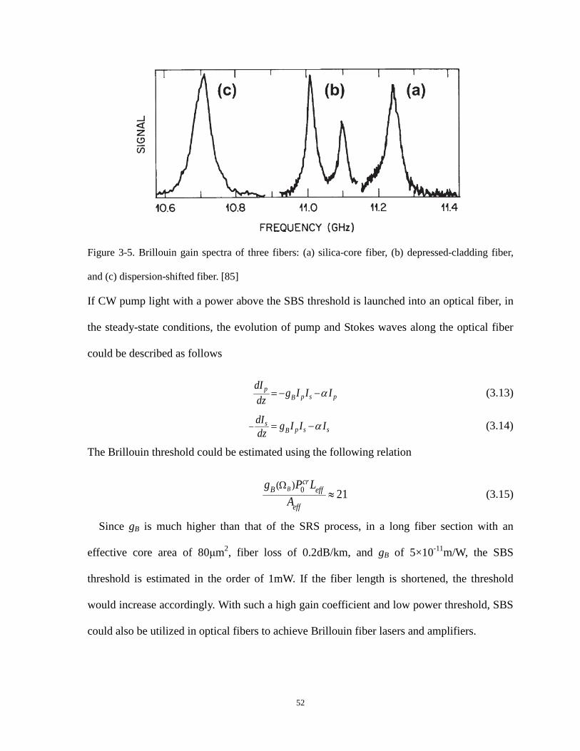
Figure 3-5. Brillouin gain spectra of three fibers: (a) silica-core fiber, (b) depressed-cladding fiber,
and (c) dispersion-shifted fiber. [85]
If CW pump light with a power above the SBS threshold is launched into an optical fiber, in
the steady-state conditions, the evolution of pump and Stokes waves along the optical fiber
could be described as follows
α= − −pp s pB
dIg I I Idz
(3.13)
α− = −sp s sB
dI g I I Idz (3.14)
The Brillouin threshold could be estimated using the following relation
0( )21
Ω≈B
crB eff
eff
g P LA (3.15)
Since gB is much higher than that of the SRS process, in a long fiber section with an
effective core area of 80μm2, fiber loss of 0.2dB/km, and gB of 5×10-11m/W, the SBS
threshold is estimated in the order of 1mW. If the fiber length is shortened, the threshold
would increase accordingly. With such a high gain coefficient and low power threshold, SBS
could also be utilized in optical fibers to achieve Brillouin fiber lasers and amplifiers.
52

Figure 3-6. Experimental setup of first demonstration of BRFL [71].
Similar to SRS based random fiber lasers, SBS is also an effective gain mechanism to
realize Brillouin random fiber lasers (BRFLs). The first BRFL was proposed and
demonstrated in 1998 by Fotiadi [71], where a narrow spectrum of Stokes lasing was
observed for the SBS process in a 300m single mode fiber with high Rayleigh scattering
coefficient. The setup is based on one-end pumping configuration with open laser cavity as
shown in Figure 3-6. As the pump light with power above the SBS threshold was launched
into the highly-scattering fiber, the Brillouin Stokes wave was generated and counter-
propagated along the fiber with respect to the pump light. The doubly-scattered Brillouin
Stokes lights would then act as the seed of the new SBS amplification processes. As long as
the gain provided by the SBS process compensates the total cavity loss in the system, the
Brillouin Stokes lasing would be obtained. It was theoretically shown in [71] that the
contribution of Rayleigh scattering makes the distribution of the Stokes output in the form of
Gaussian statistics, being completely different from that of normal SBS process, which
indeed demonstrates the existence of Brillouin lasing in such a high loss system.
53
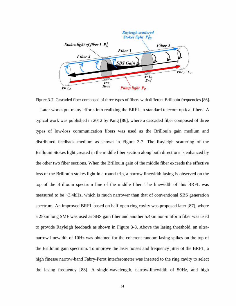
Figure 3-7. Cascaded fiber composed of three types of fibers with different Brillouin frequencies [86].
Later works put many efforts into realizing the BRFL in standard telecom optical fibers. A
typical work was published in 2012 by Pang [86], where a cascaded fiber composed of three
types of low-loss communication fibers was used as the Brillouin gain medium and
distributed feedback medium as shown in Figure 3-7. The Rayleigh scattering of the
Brillouin Stokes light created in the middle fiber section along both directions is enhanced by
the other two fiber sections. When the Brillouin gain of the middle fiber exceeds the effective
loss of the Brillouin stokes light in a round-trip, a narrow linewidth lasing is observed on the
top of the Brillouin spectrum line of the middle fiber. The linewidth of this BRFL was
measured to be ~3.4kHz, which is much narrower than that of conventional SBS generation
spectrum. An improved BRFL based on half-open ring cavity was proposed later [87], where
a 25km long SMF was used as SBS gain fiber and another 5.4km non-uniform fiber was used
to provide Rayleigh feedback as shown in Figure 3-8. Above the lasing threshold, an ultra-
narrow linewidth of 10Hz was obtained for the coherent random lasing spikes on the top of
the Brillouin gain spectrum. To improve the laser noises and frequency jitter of the BRFL, a
high finesse narrow-band Fabry-Perot interferometer was inserted to the ring cavity to select
the lasing frequency [88]. A single-wavelength, narrow-linewidth of 50Hz, and high
54

frequency stability (<40kHz frequency jitter) coherent BRFL was then achieved.
Figure 3-8. Schematic of BRFL with half-open ring cavity [87].
3.2.3 Erbium-doped fiber random laser
Erbium (Er) is a chemical element belonging to the group of rare earth metals. It is widely
used in the form of the trivalent ion Er3+ as the laser-active dopant of gain media based on
various host materials, including both crystals and glasses. The fabrication of the erbium-
doped fiber (EDF), similar to that of regular SMF, is processed by delivering the rare earth
vapor species to the reaction/deposition zone of a fiber preform through the Modified
chemical vapor deposition (MCVD). Such optical fibers doped with the rare earth elements
can be used as gain medium of a fiber laser or optical amplifier. The EDF based amplifiers
have attracted the most attention because they operate in the wavelength region near 1.55 μm.
Their deployment in WDM systems after 1995 revolutionized the field of fiber-optic
communications and led to lightwave systems with capacities exceeding 1 Tb/s.
55

Figure 3-9. Energy level structure of the erbium ion and some common optical transitions.
In order to make EDF provide gain to the lightwave systems, pumping at a suitable
wavelength is required to achieve population inversion. The gain spectrum of EDF depends
on the pumping scheme as well as on the presence of other dopants in fiber core, such as
germania and alumina. The energy levels of the Er3+ are broadened by the amorphous nature
of silica. Figure 3-9 shows a few energy levels of Er3+ in silica fibers. The most common
laser transition is that from the 4I13/2 manifold to the ground state manifold 4I15/2. Depending
on the fiber core composition, the transition wavelength is usually between 1.53 and 1.6μm.
Due to the quasi-three-level transition, a significant excitation density of the erbium ions is
required in order to decrease the threshold pump power for EDF based amplifiers and lasers.
Many transitions can be used to pump the EDF. Efficient EDF pumping uses
semiconductor lasers operating near 0.98- and 1.48-μm wavelengths. In the 0.98μm pumping
scheme, pump photons at 0.98μm are able to excite ground state carriers to the excited state
and create population inversion. Note that the carriers only stay in the excited state for about
1μs, after which they decay into a metastable state through a non-radiative transition. The
56
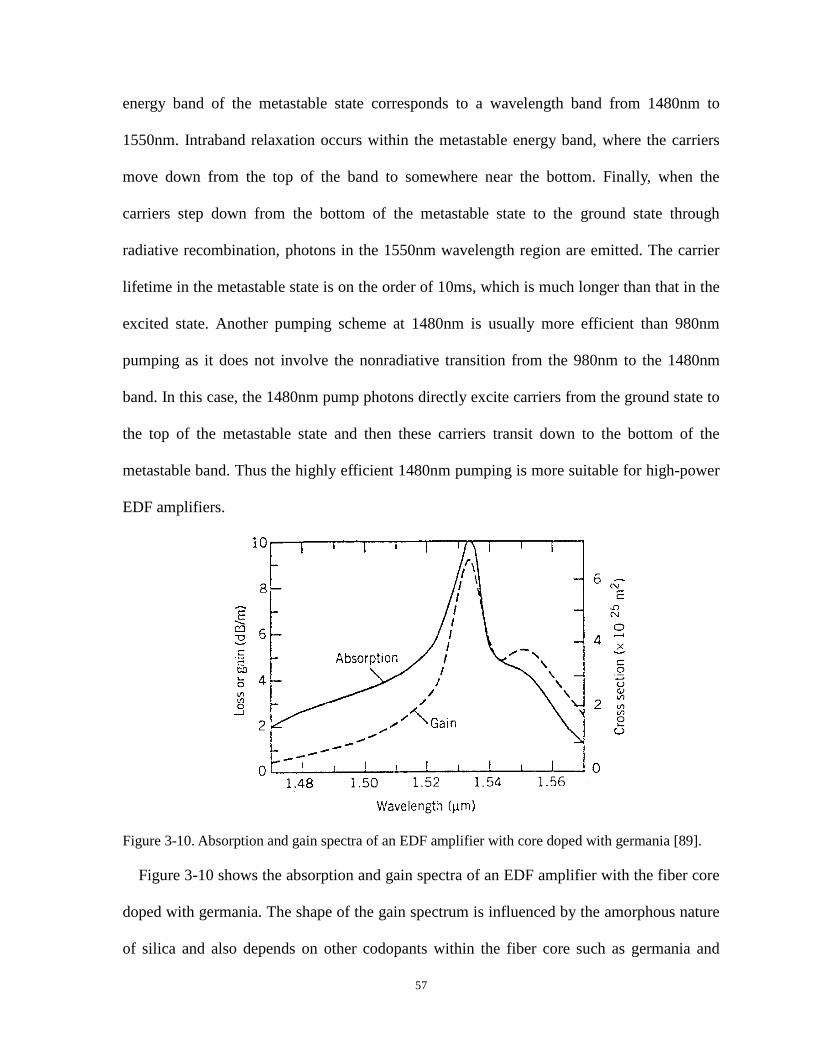
energy band of the metastable state corresponds to a wavelength band from 1480nm to
1550nm. Intraband relaxation occurs within the metastable energy band, where the carriers
move down from the top of the band to somewhere near the bottom. Finally, when the
carriers step down from the bottom of the metastable state to the ground state through
radiative recombination, photons in the 1550nm wavelength region are emitted. The carrier
lifetime in the metastable state is on the order of 10ms, which is much longer than that in the
excited state. Another pumping scheme at 1480nm is usually more efficient than 980nm
pumping as it does not involve the nonradiative transition from the 980nm to the 1480nm
band. In this case, the 1480nm pump photons directly excite carriers from the ground state to
the top of the metastable state and then these carriers transit down to the bottom of the
metastable band. Thus the highly efficient 1480nm pumping is more suitable for high-power
EDF amplifiers.
Figure 3-10. Absorption and gain spectra of an EDF amplifier with core doped with germania [89].
Figure 3-10 shows the absorption and gain spectra of an EDF amplifier with the fiber core
doped with germania. The shape of the gain spectrum is influenced by the amorphous nature
of silica and also depends on other codopants within the fiber core such as germania and
57

alumina. The gain spectrum of erbium ions alone is homogeneously broadened, whose
bandwidth is determined by the dipole relaxation time. Moreover, the Stark splitting of the
energy levels further broadens the gain spectrum homogeneously. In addition, the spectrum
could be considerably broadened in the presence of randomly located silica molecules, which
leads to inhomogeneous broadening of the gain spectrum. When the EDF is pumped for
optical amplification within the gain spectrum, the weak signal photon can stimulate the
excited erbium ions to emit photons with exactly the same wavelength and phase as the
incident photon, leading to the amplification of the incident signal.
Figure 3-11. Experimental setup of inscribing FBGs with random spacing along a Er/Ge co-doped
fiber [74].
The EDFRLs could be generally divided into two categories based on the laser
configurations. In the first category, the gain and random distributed feedback are both
provided by the EDF. This is commonly achieved by inscribing gratings along the EDF core
region. The pioneering work is proposed in 2009, where FBGs were written along an Er/Ge
co-doped SMF with random spacing [74] as shown in Figure 3-11. A complex cavity with
high quality factor resonances in the range of gain wavelengths centered around 1535.5nm
was formed by the random FBG array. The lasing behaviors, such as laser threshold, were
58

also observed in experiments. Shortly after this work, the Kashyap group proposed a novel
random FBG fabrication technique by inserting a large number of randomly distributed
phase errors in the grating structures [47]. These errors were introduced by controlling the
frictions between the fiber and the mount during the manufacturing process. Such a grating
was written in a polarization-maintaining EDF and random lasers were demonstrated by
using 976nm and 1480nm pump lasers.
Figure 3-12. Experimental setup of half-open linear cavity RDF based random fiber laser [90].
In the other category of EDFRLs, gain and random feedback are provided separately from
different fibers. EDF provides the gain and a separate fiber structure provides random
feedback. A typical work of this kind of random fiber laser was presented in 2014, where a
half-open linear cavity was formed by enclosing the EDF between an FBG and a long section
of Rayleigh scattering fiber [90] as shown in Figure 3-12. The FBG was used to reflect a
narrow wavelength band centered at 1539.4nm and with a 3 dB bandwidth of 0.03nm from
the amplified spontaneous emission of the EDF. With sufficient length for the Rayleigh
scattering fiber, the accumulated distributed feedback can be large enough to overcome the
loss induced by the half-open cavity. The proposed random fiber laser is superior to the
commercially available narrow-linewidth lasers with suppressed intensity and frequency
noises. Another work of this category was realized by constructing a ring cavity with the gain
from the EDF and random distributed feedback from a fiber random grating fabricated using
CO2 laser [75]. Around 100 randomly spaced refractive index modulation regions were
59

written over a 10cm SMF with modifications in both longitudinal and transverse directions.
The configuration achieved a tunable EDF based random fiber laser with narrow linewidth of
2.4kHz and low relative intensity noise as well as mitigated frequency jitters.
3.3 Lasing mode and linewidth characterization
As the strength of random distributed feedback from either the intrinsic Rayleigh
scattering in long standard telecom SMFs or enhanced scattering in modified fiber structures
is large enough to be amplified by the optical gain to overcome the loss in the cavity, random
lasing would build up with unique resonance properties. The random distributed scattering
centers in the random fiber medium will constitute numerous random resonant cavities,
which gives rise to large numbers of resonant modes. Thanks to the elastic nature of
Rayleigh scattering, the scattered light waves from the scattering centers could be coherently
interfered with each other. With specific gain spectral profile, such process is of high
probability to operate with single-mode emission and narrow linewidth.
3.3.1 Lasing mode
In conventional lasers, the resonance frequencies, i.e. lasing modes, are determined by the
eigen-modes of the fixed laser cavity. Typically, in a fiber ring laser with fixed ring length of
l, the cavity mode spacing can be calculated by c/nl, where c is the light velocity in vacuum
and n is the refractive index of the fiber. Provided that a specific gain profile is given, lasing
would occur at fixed cavity modes where the gain overcomes the loss. In general, such a
fixed cavity laser would support multiple longitudinal lasing modes as long as gain is high
enough and no filtering techniques with narrow bandwidth are implemented.
60

Figure 3-13. Schematic of a random fiber ring laser with Rayleigh feedback.
Situations are different in random fiber lasers with random distributed feedback from
numerous disordered scattering centers. Figure 3-13 shows a schematic of a random fiber
ring laser with Rayleigh feedback. An optical fiber amplifier provides the gain, which could
be based on the SBS process, SRS process and EDF with spectral profile tailored by a filter.
Random distributed feedback is provided by the long Rayleigh fiber, which could be
regarded as a collection of scattering centers randomly distributed along the fiber. The elastic
Rayleigh scattering feedback, which preserves the phase coherence between the incoming
and scattered light waves, leads to coherent random feedback with constructive interference.
The random lasing builds up through the combination of the coherent Rayleigh scattering in
the Rayleigh fiber and round-trip amplification by the optical gain. Note that the intra-cavity
light in the lasing system experiences the coherent Rayleigh backscattering from different
ensembles of scattering centers in the Rayleigh fiber every round-trip during the lasing build-
up process. Hence the effective laser cavity length is not constant for the random fiber
resonator every round-trip, which physically means that the photons recaptured in the open
cavity follow complex and various trajectories, while the phase correlation among them
results in multiple and complex interference peaks. Therefore, non-periodic interference
61

patterns and randomly resonant spikes in the lasing spectra are expected due to the random
distribution of the optical path length for arbitrary backscattered lights. If the polarization
effect and the phase noise terms are omitted, the lasing output from the proposed random
fiber laser could be expressed as
( ),
, , ,1 1 1
42exp( ) exp( 2 )πυπυα α
= = == − − − −∑ ∑∏
N umMu k
out S u k u k u km u k
nznLE E L i G A z ic c . (3.16)
where ES is the seed light from the amplifier, which could be Brillouin Stokes light, Raman
Stokes light or amplified spontaneous emission from EDF; L is the length of the loop
excluding the length of Rayleigh fiber; α and n are the mean loss coefficient and refractive
index, respectively; M is the total number of round-trips; Gu,k is the gain experienced by the
backscattered light from kth scattering center in uth round-trip; Au,k and zu,k are the
backscattering coefficient and position of kth scattering center in uth round-trip, respectively;
N(u) is the total number of effective scattering centers in uth round-trip and increases with
the number of round-trip times; ν is the frequency of the light.
Figure 3-14. Resonance properties of random fiber ring laser with (a) flattened gain and (b) un-
flattened gain.
Assume there are 1000 scattering centers in a 5km long Rayleigh fiber and the locations of
62
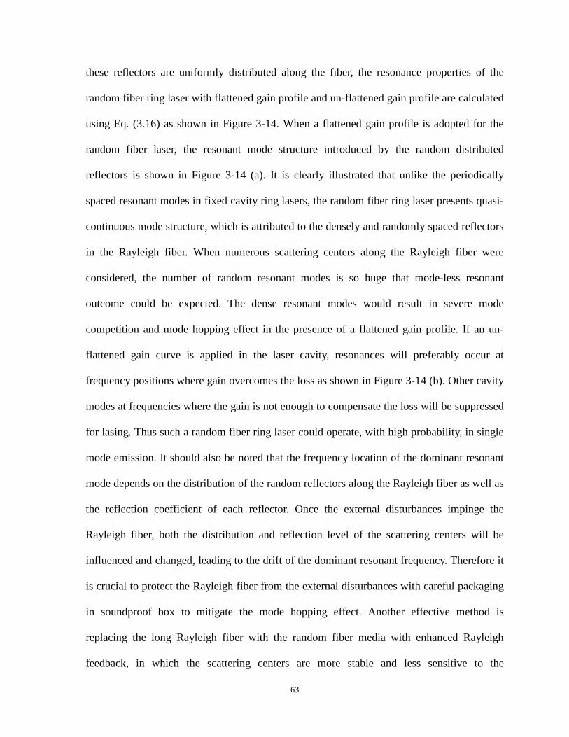
these reflectors are uniformly distributed along the fiber, the resonance properties of the
random fiber ring laser with flattened gain profile and un-flattened gain profile are calculated
using Eq. (3.16) as shown in Figure 3-14. When a flattened gain profile is adopted for the
random fiber laser, the resonant mode structure introduced by the random distributed
reflectors is shown in Figure 3-14 (a). It is clearly illustrated that unlike the periodically
spaced resonant modes in fixed cavity ring lasers, the random fiber ring laser presents quasi-
continuous mode structure, which is attributed to the densely and randomly spaced reflectors
in the Rayleigh fiber. When numerous scattering centers along the Rayleigh fiber were
considered, the number of random resonant modes is so huge that mode-less resonant
outcome could be expected. The dense resonant modes would result in severe mode
competition and mode hopping effect in the presence of a flattened gain profile. If an un-
flattened gain curve is applied in the laser cavity, resonances will preferably occur at
frequency positions where gain overcomes the loss as shown in Figure 3-14 (b). Other cavity
modes at frequencies where the gain is not enough to compensate the loss will be suppressed
for lasing. Thus such a random fiber ring laser could operate, with high probability, in single
mode emission. It should also be noted that the frequency location of the dominant resonant
mode depends on the distribution of the random reflectors along the Rayleigh fiber as well as
the reflection coefficient of each reflector. Once the external disturbances impinge the
Rayleigh fiber, both the distribution and reflection level of the scattering centers will be
influenced and changed, leading to the drift of the dominant resonant frequency. Therefore it
is crucial to protect the Rayleigh fiber from the external disturbances with careful packaging
in soundproof box to mitigate the mode hopping effect. Another effective method is
replacing the long Rayleigh fiber with the random fiber media with enhanced Rayleigh
feedback, in which the scattering centers are more stable and less sensitive to the
63

environment changes. Thus, the intensity and frequency noises are alleviated, ensuring high-
efficiency and linewidth narrowing laser output.
3.3.2 Linewidth characterization
Linewidth characterization of random fiber lasers could be conducted by employing the
delayed self-heterodyne (DSH) method. The DSH technique was firstly proposed by T.
Okoshi in 1980, in which a part of the laser output itself was frequency-shifted and used as
the local oscillator power combined with the other part of laser output after time delay [91].
This technique has afterwards been widely and extensively applied in linewidth
characterization of semiconductor lasers. Modifications and optimizations for simplifying the
experimental configurations and improving the measurement resolutions are also made on
this technique later, which include reflection-type DSH technique [92] and DSH technique
with recirculating delay [93]. Here we will focus on the conventional DSH technique and
clarify its operation principles.
Figure 3-15. Schematic of the delayed self-heterodyne technique for laser linewidth measurement.
The conventional DSH technique is based on the Mach-Zehnder interferometer (MZI) as
shown in Figure 3-15. Light from the laser under test is unequally split into two parts with
different powers and launched into the two beams of the MZI. As a long fiber delay line is
usually required for characterization of narrow-linewidth lasers, the part of light with higher
power should be sent through the beam with fiber delay and the other part of light with lower
64

power launched to the beam with frequency shifter. In this way, the two beam lights could be
combined with almost equal powers at the second optical coupler. The mixed signal would
therefore be detected by the photo-detector and electrical spectrum analyzer (ESA) with an
optimized contrast. In practical operations, an optical attenuator could be inserted into either
beam of the MZI for fine control of the transmitted light powers.
The optical field from the laser under test could be modeled as a quasi-monochromatic
amplitude-stabilized field with a phase variation as follows:
[ ( )]( ) ω φ+= j t tE t Ee . (3.17)
When the two light beams combine at the output of the MZI, the detected total field is a
superposition of the laser fields as expressed in Eq. (3.17) with a time delay for one and
frequency shift of itself for the other:
0 0) ( )1 2
[( ( )] [ ( )]( ) ω φ ω τ φ τ+Ω + + + ++= d dT
j t t j t tE t E e E e . (3.18)
where E1 and E2 are the field amplitude for each light beam, respectively; ω0 is the center
angular optical frequency; Ω is the frequency shift; τd is the time delay induced by the long
fiber delay line; ϕ(t) and ϕ(t+τd) are the initial and time-delayed phase fluctuations,
respectively. Because of the square law of optical detectors, these interferometric systems are
able to convert the quantum phase noise of the laser field ET into intensity noise and then
give a spectral spread of photocurrent I(t). For stationary fields, the autocorrelation function
RI(τ) of the photocurrent depends only on the intensity correlation function of the detected
total field [94, 95]:
(1) (2)2( ) (0) ( ) ( )τ δ τ τ= +I E ER qRG R G . (3.19)
with
(1) *(0) ( ) ( )=E T TG E t E t . (3.20)
65

(2) * *( ) ( ) ( ) ( ) ( )τ τ τ= + +E T T T TG E t E t E t E t . (3.21)
where q is the electron charge; R is the detector sensitivity; δ(τ) is the Dirac delta function.
GE(1)(0) and GE
(2)(τ) are the first-order and second-order optical intensity correlation function,
respectively. By combining Eq. (3.18) and Eq. (3.21), we have
00
00
00
00
[ ( ) ( )][( ) ( )]1 2
[ ( ) ( )][( ) ( )]1 2(2)
[ ( ) ( )][( )( ) ( )]1 2
[ ( ) ([( )( ) ( )]1 2
( )
( )( )
( )
(
ω τ φ τω φ
ω τ φ τω φ
ω τ τ φ τ τω τ φ
ω τ τ φ τω τ φ
τ
+ + ++Ω +
− + + +− +Ω +
+ + + + ++Ω + +
− + + + + +− +Ω + +
+
+=
+
+
d d
d d
d d
d d
j t tj t t
j t tj t t
E j t tj t t
j t tj t t
E e E eE e E e
GE e E eE e E e )])τ
. (3.22)
The above equation could be simplified as
[ ( ) ( )] [ ( ) ( )](2) 2 2 2 2 2 2 21 2 1 2 1 2
[ ( ) ( )]2 2 2 2 21 2 1 2
( ) ( )
( ) 2 cos( )
φ τ τ φ τ φ τ τ φ ττ τ
φ τ τ φ τ
τ
τ
+ + − + + + − +Ω − Ω
+ + − +
= + + +
= + + Ω
d d d d
d d
j t t j t tj jE
j t t
G E E E E e e E E e e
E E E E e. (3.23)
By using the following well-known relation [96]:
21 ( )( , ) 2 φ τφ τ − ∆± ∆ =j te e . (3.24)
Eq. (3.23) could be expressed as
21 ( )(2) 2 2 2 2 2 21 2 1 2( ) ( ) 2 cos( )
φ ττ τ
− ∆= + + ΩEG E E E E e . (3.25)
where
( ) ( ) ( )φ τ φ τ τ φ τ∆ = + + − +d dt t . (3.26)
By assuming the mean-square phase jitter in Eq. (3.25) increases linearly with the time
delay as
2( ) 2φ τ γ τ∆ = . (3.27)
where 2γ is the angular full linewidth at half maximum of the Lorentzian laser field spectrum.
Eq. (3.25) could thus be written as
66

(2) 2 2 2 2 21 2 1 2
,( ) ( ) 2 cos( )
,
γτ
γτ
τ ττ τ
τ τ
−
−
<= + + Ω
>
d
dE
d
eG E E E E
e. (3.28)
By virtue of the Wiener-Khintchine theorem, the spectrum of the detected photocurrent is
given by performing a Fourier transform of Eq. (3.19):
( ) ( ) ωτω τ τ∞
−
−∞= ∫ j
I IS R e d . (3.29)
If the shot noise term of Eq. (3.19) is omitted, the two-sided spectrum is written as
2 22 2 2 2 2 2 21 2 1 2 1 2
2
2
2
1/( ) ( ) ( )2 2 1 ( )2( ) sin( )22[ cos( )2 ]2
2
γτ γτ
γτ
ω ω πδ δ ωγ γγ
ω ω γτγ ω γτω γγ
− −
−Ω+ + + −Ω+
= −Ω−Ω− −−Ω
d d
d
Id
d
E E E E e E E e
S R
e
. (3.30)
If the time delay meets the following relation that the two beam lights are not coherent
2πτγ
2d . (3.31)
Eq. (3.30) could be written as
2 2 2 2 2 21 2 1 2
2
22 2 2 2 2 2
1 2 1 2 2 2
1/( ) ( ) ( )2 1 ( )2
(4 / 2) /( ) ( )2 (4 / 2) ( )
ω πω δ ωγγ
γ πωδγ γ ω
= + + −Ω+
= + ++ −Ω
IS R E E E E
R E E E E
. (3.32)
In this case, the beat spectrum has a Lorentzian shape and its FWHM (=4γ) is twice the
laser’s FWHM (=2γ). Eq. (3.31) requires the delay line long enough in order to obtain the
FWHM of the laser under test from a Lorentzian spectrum. However, it is difficult to meet
this requirement especially for narrow-linewidth lasers in practical as the delay line should
be at least longer than 200km for a 1kHz linewidth laser. In this case, the obtained beat
67

spectrum is not exactly a Lorentzian shape, leading to some measurement errors. For the
linewidth characterization of random fiber lasers, due to the instability of the lasing modes,
the beat spectrum from the DSH technique is actually an averaged result over the long delay
time induced by the fiber delay line. As a result, the instantaneous linewidth of the random
fiber laser cannot be observed and would be smaller than that obtained from the DSH method.
This could be improved by employing the heterodyne detection method, which no longer
utilizes the beating between the laser output and itself, but rather builds up two identical
lasers under test and mixes them together with frequency shift. In this way, as long as the two
lasers are independently operating and have no phase correlation, the instantaneous linewidth
could be determined directly without using long fiber delay lines.
3.4 Intensity noise measurement
Intensity noise is a key parameter for evaluating the performance of a laser. Laser intensity
noise originates from both the quantum noise and technical noise sources. Quantum noises
are associated with laser gain and resonator losses. Technical noise sources include the
vibration of resonator mirrors, noise of pump lasers, thermal variations in gain medium. A
fundamental limit to the intensity noise is given by shot noise, which is related to the
discreteness of photons and electrons. It was originally thought to arise from the random
occurrence of photon absorption events in a photo-detector. However, it was proved later that
shot noise is also closely related to the light field itself. Shot noise level can be approached
by most lasers at high noise frequencies well above the relaxation oscillation frequencies.
The technical issue induced intensity noises usually dominate in the relatively low frequency
region, which could be characterized by recording the power variations of the laser in the
time domain.
68

Figure 3-16. Schematic of the RIN measurement setup.
Since the laser intensity noise is usually linearly proportional to signal optical power, it is
more precise to normalize the intensity noise by the total laser output power. Thus the
parameter, relative intensity noise (RIN), is defined as the ratio between the noise power
spectral density and the total output power. Figure 3-16 shows the block diagram of a RIN
measurement setup. Output from the laser under test is directly detected by a wideband DC-
coupled photo-detector and the detected signal is analyzed in an ESA. Alternatively an
oscilloscope could be used to record the time series of laser output and the data can be
processed manually. Without intensity noise in the laser under test, there is obviously only a
DC component on the ESA spectrum. When the intensity noise is present, the power
fluctuation of the laser induces the variations of detected photocurrent, the spectral density of
which is measured by the ESA. Because of the square-law detection principle of the photo-
detector, the electrical power PPD generated at the output of a photo-detector is proportional
to the square of the received laser power Pout. Therefore, the RIN can be defined as the ratio
between noise power spectral density and the signal power in the electrical domain as
follows:
, ,2,
1( ) ( ( ) ) ( ( ) ) ωτω τ τ+∞
−
−∞= − + −∫
jout out ave out out ave
out aveRIN P t P P t P e d
P. (3.33)
where Pout,ave is the averaged output power of the laser under test. In practice, the ESA
directly measures the photocurrent spectral density, which is denoted as SP(ω). If the detector
69

responsivity is R, the measured RIN can be obtained as
2 2,
( )( ) P
out ave
SRINR P
ωω = . (3.34)
The unit of RIN is Hz-1 or dB/Hz as a relative measurement.
Figure 3-17. RIN comparison between half-open linear cavity Rayleigh random fiber laser (blue),
half-open ring cavity random fiber laser with random grating feedback induced by CO2 laser (red),
and commercial fiber laser (green). [75]
Stable single-mode semiconductor lasers usually have very low RIN level below -
155dB/Hz in the low frequency spectral range, which is mainly attributed to the stable cavity
with thermal feedback control, single-mode operation without mode competition and mode
hopping effect as well as high frequency feature of gain dynamics. However, in random fiber
lasers, due to several negative factors, the RINs are relatively higher than the conventional
semiconductor or fiber lasers. Figure 3-17 shows previously reported RIN measurement
results comparing random fiber lasers and commercial fiber laser. The higher RIN in random
fiber lasers is mainly due to the random distributed feedback mechanism based on Rayleigh
70

scattering or enhanced Rayleigh scattering, which does not support a fixed cavity mode but
rather large numbers of quasi-continuous modes. This introduces severe mode competition
and mode hopping in the laser system when mode locking mechanism is not available. In
addition, the gain dynamics plays an important role in influencing the RIN. As EDF gain
with a decay time in the order of millisecond was used in that work, the relaxation oscillation
noises were intensified by the strong mode competition, leading to distinct RIN peaks around
kHz range. For Brillouin random fiber lasers, this gain dynamics induced RIN is also
observed, which will be discussed in later chapters.
3.5 Frequency noise measurement
Another key parameter for evaluating laser performance is the frequency noise and its
measurement has been one of the most attractive subjects of researches in laser and
photonics field. An ideal single-frequency laser has stable and unchanged lasing frequency
with low frequency noise, which is only subject to quantum noise and exhibits the
Schawlow-Townes linewidth. However, due to the laser cavity change and gain variations
induced by the external disturbances, in practice lasing frequency will suffer from shift
respect to the original resonant frequency. The frequency noise measurement of a laser is
used to describe the level of random fluctuations of the instantaneous lasing frequency. A
laser with lower frequency noise is more stable with lasing frequency and is usually
associated with narrow linewidth.
The optical field from an ideal laser could be modeled as a monochromatic amplitude-
stabilized field with a phase variation as follows:
0 0( ) cos(2 )πυ=E t E t . (3.35)
71

If the time-dependent phase fluctuations are considered, the above equation should be
modified as
0 0 0( ) cos(2 ( )) cos( ( ))πυ φ= + = ΦE t E t t E t . (3.36)
The instantaneous optical frequency of the laser could be obtained by calculating the time
derivative of the total phase Φ(t) in Eq. (3.36) as follows:
0 0( ) ( )1 1 ( )2 2
φυ υ υ υπ π
Φ= = + = +∆d t d t tdt dt. (3.37)
where Δν(t) is the time-dependent frequency fluctuation. The frequency noise could be
obtained by computing the power spectral density of the time-dependent frequency
fluctuation:
2( ) ( ( ) ( ) ) ( ) ( ) π τυ υ υ τ υ υ τ τ
∞−
−∞= ℑ ∆ ∆ + = ∆ ∆ +∫ j fS f t t t t e d . (3.38)
The fundamental limit to the frequency noise is determined by the spontaneous emission in
the laser gain medium, which also gives rise to the limitation to the laser linewidth, namely,
the Schawlow-Townes noise limit. The two-sided frequency noise power spectral density of
this limitation is expressed as [97]
32 0
, 2( ) (1 )υ α= +sp sphvS f nQ P
. (3.39)
where nsp is the normalized inversion, h is Planck’s constant, v0 is the laser frequency, P is
the output power, α is the linewidth enhancement factor, and Q is the quality factor, given by
the ratio of the laser frequency and cavity linewidth. An increase in cavity Q and/or laser
power P would result in a reduction in Sv,sp (f). However, this limit cannot be reached by most
of laser sources, particularly at low frequencies, due to other noise sources induced by the
cavity variations and thermal variations in gain medium.
72

Figure 3-18. (a) Conventional Fabry-Perot resonator with fixed cavity; (b) random fiber laser with
random distributed feedback.
In random fiber lasers, the expression of power spectral density of the frequency noise
could be derived using the model shown in Figure 3-18. For a conventional FP resonator
with fixed cavity as shown in Figure 3-18(a), if the intra-cavity light is Ein with optical
frequency of v0, its reflection from the mirror could be written as
0( )0( ) ( ) φ τ−= j t
r inE t E t R e . (3.40)
The frequency noise for the FP cavity can be determined from the delayed phase
perturbations contributed by the single reflector and hence can be written as:
0 0( ) ( ( ) ( ) )ω φ τ φ τ τ= ℑ − − +
FPS t t . (3.41)
Similarly, the reflected light field in random fiber laser with random feedback from N
Rayleigh scattering centers as shown in Figure 3-18(b) could be written as
( )'
1( ) ( ) φ τ−
== ∑ i
Nj t
r in ii
E t E t R e . (3.42)
where τi and Ri are the delay time and reflection coefficient at ith scattering center. By
performing the approximation of ex ≈ 1+x on Eq. (3.42), we have
73

' 1
1 1
1
1
( )( ) ( ) [1 ( )] ( ) [1 ]
( ) [1 ( )]
φ τφ τ =
= =
=
=
−= + − = +
= + Φ
∑∑ ∑
∑
∑
N
i iN Ni
r in i i in i Ni i
ii
N
in ii
R tE t E t R j t E t R j
R
E t R j t
. (3.43)
Hence, if the phase introduced by the scattering centers is small, we can claim the net phase
shift for the random laser to be a statistical average of all the phase shift terms, where each
term is weighted by the normalized reflectivity Ri/N. In this case, the frequency noise for the
random laser is:
1 1
1 1
( ( ) ( ) )( ) ( ( ) ( ) )
φ τ φ τ τω τ = =
= =
ℑ − − += ℑ Φ Φ + =
∑∑
∑ ∑
N N
i ik ki k
R N N
i ki k
R R t tS t t
R R. (3.44)
Figure 3-19. Experimental setup used to measure the laser phase and frequency noise [98].
The frequency noise of a laser could be measured using phase demodulation method based
on an imbalanced symmetric 3×3 coupler Michelson interferometer (MI) with a delay line in
one arm as shown in Figure 3-19. It consists of a commercially available 3×3 optical fiber
coupler (OC), a circulator (C), two Faraday rotator mirrors (FRMs), three photodetectors
(PDs), a data acquisition board (DAC) or a digital oscilloscope, and a computer. An
unbalanced Michelson interferometer is composed of the 3×3 coupler and the FRMs. The
74

FRM will remove the polarization fading of interferometer, caused by external disturbance
on its two beam fibers. The laser under test (LUT) injects the left port 1 of the 3×3 optical
fiber coupler through a circulator and then splits into 3 parts by the coupler. Two of them
interfere mutually in the coupler after reflected by Faraday mirrors and with different delay
times, and the third part of them is made reflection-free. Then the interference fringes are
obtained from the left port 1, 2, 3 of the coupler, and read by a DAC or a digital oscilloscope.
Following the derivation in [99], the differential phase fluctuation Δφ(t) of the laser under
test accumulated in the delay time τ could be obtained through measuring the three intensity
outputs in Fig. 3-19:
' '2 2' '1 1
( ) ( )( ) ( ) ( ) arctan( ) arctan( )( ) ( )
——————————
ϕ ϕ ϕ τ∆ = − − = −X t X tt t tX t X t
. (3.45)
where φ(t) is the instantaneous phase fluctuation of LUT at time t, X1’(t) and X2’(t) are
expressed as:
-1'1 1 1 1 1'2 2 2 2 2'
3 3 3 33
( ) ( )( ) = ( )
( )( )
η ς ξη ς ξη ς ξ
X t I tX t I t
I tX t. (3.46)
where ηn=2rncn1cn2cos(θ′n2+θ21-θ′n1-θ11), ςn=2rncn1cn2sin(θ′n2+θ21-θ′n1-θ11), ξn=rn[(cn1)2+(cn2)2],
cnm=pmmb′ nmbm1, n=1, 2, 3 is the output port number of MI, and m=1, 2 is the interference
arm port number. pmm is the transmission loss of the interference arm, bmn and θmn are the
splitting ratio and phase delay from the port n to port m of coupler, b′mn and θ′mn are the
splitting ratio and phase delay from the port m to port n of coupler, rn is the responsivity of
PDs. So the parameters ηn, ςn, ξn are constant for the setup once the devices and structure are
determined. The power spectral density (PSD) of differential phase fluctuation Δφ(t) and
differential frequency fluctuation Δν(t) can be calculated respectively in the computer by
75

PSD estimation method [100]. If the calculated phase and frequency noises are denoted as
SΔφ(f) and SΔv(f), respectively, through the following fixed relations:
21( ) ( )2υ ϕπτ∆ ∆
=S f S f . (3.47)
2
2 21( ) ( ) ( )
4(sin( )) (sin ( ))υ ϕ υπ τ π τ∆ ∆= =fS f S f S ff c f
. (3.48)
The instantaneous frequency fluctuations, i.e. frequency noise, can be expressed as
2
21 1( ) ( )2(sin ( ))υ ϕπτπ τ ∆
=S f S fc f
. (3.49)
3.6 Applications of random fiber lasers
So far, with the unique lasing feature and simple configurations, random fiber lasers,
especially Raman random fiber lasers, have found applications widely extending to various
areas including fiber telecommunication applications, remote fiber-optic point sensing
systems, and distributed amplification in distributed sensing systems.
In fiber telecommunication applications, the Raman random fiber lasers could be utilized
to provide distributed Raman amplification in a long-haul fiber span. The stable lasing output
and simple design make the Raman random fiber laser an ideal source for the amplification
of ultra-long telecommunication systems without undesired impairment induced by nonlinear
effects or compromised signal-noise-ratio with inconstant gain distribution along the fiber
length. The forward pumping Raman random fiber lasers have even shown lower effective
noise figure than that of bi-directional 1st-order and 2nd-order pumping [101], which provide
a new approach to enhance the performance of the amplified signals in long-haul systems
with less noise figures.
76

As a fact, the Raman random fiber lasers have shown stable lasing spectrum with different
environmental conditions [102]. In order to apply the Raman random fiber laser in a sensing
system, a device with parameter dependence should be introduced into the system as the
sensing head. In [102], a remote fiber-optic point sensing system was built up based on
Raman random lasing in a half-open cavity composed of a 100km long fiber span and an
FBG as point reflector. Meanwhile, the FBG reflector acted as a spectral filter, ensuring the
random lasing at a specific wavelength regardless the broad gain spectrum of the Raman
scattering. Since FBG is a temperature sensitive device and its Bragg wavelength is shifted
as a function of temperature, the lasing wavelength of such a Raman random fiber laser
would shift accordingly. By calibrating the lasing wavelength shift with the temperature
variation, real temperature at remote end of the long fiber could be quantified. This remote
point sensing system is purely passive and far (>100km) from the interrogator, which is an
ideal alternative for sensing in harsh environments. Later another remote point sensing
system with even longer fiber length (~200km) was reported [103]. Quasi-distributed remote
sensing is also available by concatenating a number of FBGs with different Bragg
wavelengths [81], which is also possible for simultaneous multi-parameter sensing.
The Raman random fiber laser could also be incorporated into a Brillouin optical time
domain analysis system to provide distributed amplification to increase the SNR of the signal
for sensing [104]. The reported system allows continuous sensing of temperature over a 122
km fiber span with 2 m spatial resolution and 14°C temperature accuracy. Furthermore,
Raman random fiber laser can be incorporated into other types of distributed fiber-optic
sensing systems such as the phase-sensitive optical time domain reflectometry. In [105], the
sensing range of the system is extended to 175km with the assistance of Raman amplification.
The ultra-long random fiber lasers have led to new promising applications in
77

telecommunications and distributed sensing as described above. A disordered lasing medium
of several hundred kilometers may be also very interesting for potential applications in
secure communications, which would give rise to a new type of classical key distribution
system that might overcome the practical challenges faced by quantum key distribution
systems. The previously reported high-quality Brillouin [86-88] and EDF [75, 106] based
random fiber lasers with low noise feature and narrow linewidth could find promising
applications in high-resolution spectroscopy, coherent communication, optical sensing, and
optical imaging.
78

Chapter 4 Random Fabry–Perot
resonator-based sub-kHz Brillouin
random fiber laser and its application in
linewidth measurement
This chapter presents the physics, experimental realization, and application of a novel
Brillouin random fiber laser. The novel Brillouin random fiber laser is based on the bi-
directionally pumped stimulated Brillouin scattering (SBS) in a 10-km-long optical fiber. A
random fiber Fabry–Perot (FP) resonator is built up through the pump depletion effects of
SBS at both ends of the fiber. A theoretical model is developed to reveal the physics behind
the unique random FP resonator that enables narrow random lasing emission. The novel laser
is successfully applied for linewidth characterization beyond 860 Hz of light source under
test. Section 4.1 gives the background of random lasers, the previously reported Brillouin
random fiber lasers and laser linewidth characterization. Section 4.2 introduces the
theoretical model of the novel Brillouin random fiber laser. Section 4.3 shows the
experimental realization of the Brillouin random fiber laser and its application in laser
linewidth measurement. Section 4.4 draws the final conclusion.
4.1 Introduction
Conventional lasers consist of a gain medium that amplifies light and a resonant feedback
mechanism, which traps the light to obtain efficient amplification, and determines the
79

eigenmodes of the laser. As the gain exceeds loss, the active resonator starts to lase.
Convention was broken when Ambartsumyan et al. proposed a novel laser with the non-
resonant feedback [15] in 1966, where the resonant frequency is only determined by the
frequency of the maximum gain. Three decades later the term random lasers, a novel kind of
laser action based on phase-coherent multiple scattering and amplification of radiations [17,
107-110], was coined by Wiersma et al. [12]. Light rays penetrating into disordered materials
are multiply scattered by wavelength-scale inhomogeneities and follow a random walk,
resembling the Brownian motion of particles suspended in a liquid. Meanwhile the light rays
are still subject to interference effects thanks to the coherent phase feedback [111], leading to
determining emission properties of random lasers such as the central frequency, bandwidth,
lifetime and a complex spatial profile. The narrow spikes on the top of an overall narrow
emission spectrum have been demonstrated by using a powdered semiconductor such as zinc
oxide [19]. Different types of random lasers have been reported using various three
dimension (3D) materials such as rare-earth powders [112], human tissues [25], and polymer
films with silver nanoparticles [113]. In order to improve the random lasing directionality
and efficiency, several types of random fiber lasers were demonstrated recently. An organic
dye with nanoparticles was filled into the hollow core of the photonic crystal fiber to form
the diffusive random fiber laser [68]. Coherent RFLs were also created by combining Er-
doped fiber working as gain medium and distributed Bragg gratings providing random phase
feedback [47, 74]. Another random fiber laser based on the Raman amplification and
Rayleigh distributed feedback was also reported in [27].
Recently, a Brillouin-gain-based random fiber laser has been demonstrated [86]. The laser
is pumped from one end and consists of three different fiber spans that were spliced together.
The middle fiber provides high Brillouin gain for the Stokes wave amplification, which is
80

created by the 3rd section fiber, and the 1st section of the fiber is used to enhance random
feedback via the Rayleigh backscattering. Above SBS generation threshold, the Stokes wave
starts to lase with spectral width of 3.4 kHz that is 3 orders of magnitude smaller than that of
the Brillouin gain profile.
Linewidth characterization has been extensively studied and investigated as narrow-
linewidth lasers are massively designed and proposed in many fields such as
telecommunications, atomic physics, microwave generations and metrology recently [114-
116]. As one of the most important parameters of a laser, laser spectra contain most of the
information about the intrinsic laser properties and are commonly regarded as a benchmark
for the lasing performance. Conventional diffraction grating based or FPI based optical
spectrum analyzers [117, 118] have been found with strong limitations in high-resolution and
high dynamic range measurements. Other conventional techniques which transform
frequency fluctuations to intensity information based on heterodyne and homodyne
detections using MZIs [119, 120] have realized high resolution up to kHz. However,
prerequisite conditions such as uncorrelation between the signal and a replica of itself with a
modulated frequency or not must be met in order to obtain a precise beating signal without
any contributions from coherence. Technical difficulties emerge when a long delay line is
inserted for this purpose. This problem worsens especially for narrower lasers where much
longer delay line and complex interpretations for delay times become necessary. To
overcome the drawbacks of high loss and technical difficulties brought by extremely long
fiber delay line, the loss-compensated recirculating delayed self-heterodyne interferometer
[121, 122] whose delay line is not required to be longer than the coherence length of the laser
under test was developed for narrow linewidth measurement. However, the resultant beating
signals are inevitably degraded by the multi-interferences due to the recirculation, and
81

complicated signal processing methods must be adopted to remove the negative effects.
Newly proposed techniques include spectrum analysis based on the SBS effects by either
characterizing the amplified Stokes light or utilizing the beating between the amplified
narrow Stoke light and the signal under test [123, 124]. They have been reported to achieve a
high frequency resolution up to 10MHz limited by the Brillouin gain bandwidth over the
whole C and L telecommunication bands. However, cost is raised as extra scanning tunable
laser source is needed to reconstruct the spectrum of signal under test. A novel method based
of the Brillouin fiber laser (BFL) is later proposed to get rid of the extra laser source [125],
which only employs the laser under test itself. The beating spectrum of the build-up BFL and
part of the light from laser under test was analyzed with a finer resolution up to kHz which is
restricted by the properties of the constructed BFL. The main drawback of possible multi-
mode lasing, however, deteriorates the stability of the BFL.
In this chapter, we propose for the first time a novel Brillouin random fiber laser (BRFL)
based on bi-directional pumping scheme, which has achieved a lasing output with narrow
linewidth of ~860 Hz. A new model of random fiber FP resonator that is built up through the
pump depletion effects of SBS and the feedback of Rayleigh backscattering is developed to
understand the physics behind the bi-directionally pumped BRFL. Compared with traditional
linewidth characterization based on the delayed self-heterodyne (DSH) technique, where
200-km fiber must be used in order to achieve 1-kHz resolution of the linewidth
measurement, the proposed extremely simple and compact narrow-linewidth laser provides a
new tool for narrow linewidth characterization of less than 1 kHz by using only 10-km fiber.
4.2 Theoretical model
The configuration of the random fiber FP resonator is shown in Fig. 4-1. Two pump lights
82

EP,A and EP,B with equal power from the same source are launched into the two ends of the
optical fiber respectively, which would be scattered from the refractive index fluctuation
associated with an acoustic wave of frequency ΩB, leading to the generation of Brillouin
Stokes light that propagates opposite to the pump light and has a frequency downshift of ΩB
with respect to the pump light due to the Doppler effect. The Stokes light ES,A (or ES,B) is
amplified through the nonlinear electrostriction mechanism along the Brillouin gain fiber.
Once pump depletion is triggered with high pump power as the gain parameter G=gIP(0)L is
well above the threshold for SBS, the effective amplification length is no longer the length of
optical fiber L but rather determined by Is(Leff)=Is(0)/e which only accounts for a relatively
short length due to the high pump intensity. As a result, most energy of Brillouin Stokes light
is stored in both ends of the gain fiber. It is noticed that due to the short interaction length
between the first-order Stokes light and the acoustic wave, higher-order Stokes light
generation in cascaded SBS process is significantly suppressed. Another co-existing
scattering mechanism is the Rayleigh scattering which provides the random phase feedback,
leading to the formation of distributed Rayleigh mirrors along the fiber. However, only the
Rayleigh mirrors located within the pump depletion regions where Stokes light dominates
are capable of offering effective Brillouin Stokes feedback and form two “mirror clouds” at
both ends of the fiber as shown in Figure 4-1. Although the reflection coefficient of the
distributed Rayleigh mirrors is extremely small (~7.3×10⁻⁵/km), the Rayleigh scattered
Stokes light at one end is then re-amplified by the pump with a great gain at the other end,
leading to the loss compensation. Consequently, the two Rayleigh mirror clouds located at
both ends of the optical fiber constitute the random FP resonator.
83

Figure 4-1. Configuration of random fiber FP resonator based Brillouin fiber laser.
Note that the cavity length LRay is not constant for the random fiber FP resonator and
follows a random process statistically with the expected value L0 which is approximately
equal to 2L and the standard deviation σL. Therefore, non-periodic interference patterns in
spectra are expected due to a random distribution of the optical path length for arbitrary
round-trip, leading to lasing for some spectral components inside the SBS gain profile. If the
polarization effect is omitted, the optical field emitted from the output port A is given by Eq.
(4.1):
,, 2,, , , 2 2 1
1 1
Ray mRay mkN i nLL c
B mout A S A A m m mk m
E E e G R G R enπα −−
−= =
=∑ ∏ (4.1)
where LRay,m is the optical path length of m-th round-trip; α and n are the mean loss
coefficient and refractive index respectively; GA,m and GB,m are the SBS amplification
coefficients for m-th round-trip induced by pump light EP,A and EP,B respectively; R2m-1 and
R2m are the distributed Rayleigh reflection coefficients in energy-stored regions near port A
and port B respectively; ν is the optical frequency and c is the speed of light in vacuum.
The power evolutions of the pump light PP,A and PP,B, SBS Stokes light PS,A and PS,B in the
gain fiber are given in Eq. (4.2):
84

,,, , , , , ,
,, ,, , , ,
,, ,, , , , ,
,, ,, , , ,
( +2 )
( +2 )
( +2 )
( +2 )
P AB P BP A S A S B S A S B P A
S AB P B P BS A P A P A S A
P BB P B P BS B S A S A S B P A
S BB P B P BS B P A P A S B
Pg P P rP rP P P rPz
Pg P P rP rP P Pz
Pg P P rP rP P P rPz
Pg P P rP rP P Pz
α
α
α
α
∂= − + − +
∂∂
= − + +∂
∂= + + −
∂∂
= + −∂
(4.2)
where gB is the Brillouin gain factor; α is the linear loss coefficient and r is the Rayleigh
backscattered coefficient.
Table 4-1. Simulation parameters
SBS gain fiber Fiber type SMF28
L (km) 10 gB (m-1W-1) 0.21 α (m-1) 4.4∙10-5 r (m-1) 7.3∙10-8
PP,A|z=0, PP,B|z=L (W) 0.035 PS,A|z= L, PS,B|z=0 (W) 0.66∙10-9
Using Eq. (4.2) and simulation parameters listed in Table 4-1, the power distributions of
PP,A, PP,B, PS,A and PS,B along the SBS gain fiber were simulated. As shown in Figure 4-2(a),
PS experiences an exponential growth only in a relatively short length at both ends of the
fiber, accompanying with strong depletion effects of PP. The effective amplification length is
calculated around 0.25 km which offers estimations for L0≈19.5 km and σL≈0.5 km.
85
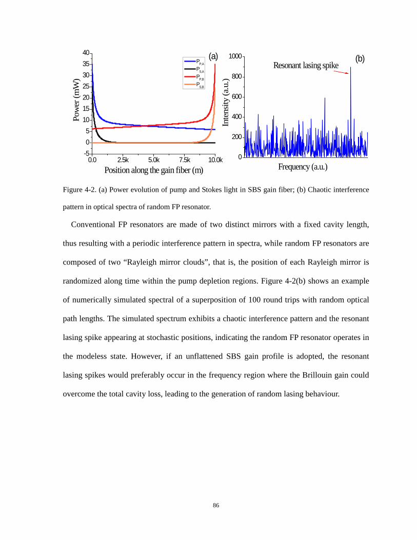
0.0 2.5k 5.0k 7.5k 10.0k-505
10152025303540
0
200
400
600
800
1000 (b)
Pow
er (m
W)
Position along the gain fiber (m)
PP,A
PS,A
PP,B
PS,B
(a)
Inte
nsity
(a.u
.)
Frequency (a.u.)
Resonant lasing spike
Figure 4-2. (a) Power evolution of pump and Stokes light in SBS gain fiber; (b) Chaotic interference
pattern in optical spectra of random FP resonator.
Conventional FP resonators are made of two distinct mirrors with a fixed cavity length,
thus resulting with a periodic interference pattern in spectra, while random FP resonators are
composed of two “Rayleigh mirror clouds”, that is, the position of each Rayleigh mirror is
randomized along time within the pump depletion regions. Figure 4-2(b) shows an example
of numerically simulated spectral of a superposition of 100 round trips with random optical
path lengths. The simulated spectrum exhibits a chaotic interference pattern and the resonant
lasing spike appearing at stochastic positions, indicating the random FP resonator operates in
the modeless state. However, if an unflattened SBS gain profile is adopted, the resonant
lasing spikes would preferably occur in the frequency region where the Brillouin gain could
overcome the total cavity loss, leading to the generation of random lasing behaviour.
86

4.3 Experimental results
Figure 4-3. Experimental setup of the random fiber FP resonator based Brillouin fiber laser. 3→a:
Conventional delayed self-heterodyne method; 3→b: Proposed linewidth measurement method.
The experimental setup of the BRFL is shown in the upper part of Figure 4-3. Light from a
1550nm fiber laser (NP Photonics) with a linewidth of ~3 kHz was firstly amplified by an
erbium-doped fiber amplifier (EDFA) and then split into two equal parts by a 50/50 coupler.
The bi-direction pumping scheme was built up by launching each part of the light to each
end of a 10km long single mode fiber (SMF28) inside an aluminous soundproof box
isolating from external disturbance. An isolator was inserted in the upper light path to protect
the EDFA from the backward scattered Stokes light. To guarantee a highly pure Stokes lasing
output, a narrow optical filter (~3GHz) was used to remove the un-depleted pump light from
the output at port 3 of the circulator. The threshold power of the proposed laser was
measured to be 10mW for each pump light by varying the amplification magnitude of the
EDFA as shown in Figure 4-4(a).
87

Figure 4-4. Threshold (a) and linewidth measurement result (b) of the proposed BRFL.
It is necessary to characterize the linewidth of the proposed BRFL itself before being
applied in linewidth measurement for other light sources. A conventional DSH method was
employed by connecting port 3 of the circulator with port a in Figure 4-3. The laser output
was divided into two parts by a 90/10 coupler with the larger part launched into the fiber
delay line and the smaller part through an acousto-optic modulator (AOM) which
downshifted the optical frequency of laser light by 40MHz. A photo detector was put after
the recombination of the two light beams to detect the beat spectrum centered at 40MHz,
which was observed in an electrical spectrum analyzer (ESA).
The length of the delay fiber is selected with 250km in the linewidth measurement and
experimental result is given in Figure 4-4(b). It is illustrated that the 20-dB linewidths of the
measurement result is ~17.2±0.17 kHz, which corresponds to 860.0±8.5 Hz for 3-dB
linewidth. The resultant narrower linewidth was due to the narrowing effects induced by the
random fiber FP resonator that was built up through bi-direction pumped SBS processes at
both ends of 10km fiber cavity. Note that the lasing threshold varies with the fiber cavity
length which however has little influence on the linewidth of the proposed random laser once
the lasing is initiated. Based on aforementioned facts, the proposed BRFLs could be utilized
88

as an effective reference for measuring linewidth beyond 860 Hz.
Characterizing the linewidth of the pump laser is carried out by connecting port 3 of the
circulator with port b in Figure 4-3. Thus the detected signal is the beating spectrum between
the depleted pump light and Stoke lasing light centered at 10.87GHz. The powers of depleted
pump light and Stokes lasing light are adjusted approximately equally in order to obtain the
beat signal with optimal visibility. Due to the unique feature of the random FP resonator
induced by pump depletion effect of SBS, the output beat spectrum drifts within a range of
several Megahertz, which could be attributed to the following two reasons: 1). The random
FP resonator is built up through pump depletion at both ends of the 10km fiber with each
mirror cloud extending 250m long within which Brillouin gain could overcome the loss due
to Rayleigh backscattering. The pump depletion regions contribute the Rayleigh scattering of
the Stokes light dominantly compared with other regions of the fiber. As the Rayleigh
mirrors are randomly distributed within the two 250m fiber regions, the phase shift
2πnLRay,mν/c in Eq. (4.1) induced by any two Rayleigh mirrors located at each end of the
fiber varies with time. As a result, the resonance frequency keeps changing as different
resonance occurs at different times. 2). The thermally fluctuating refractive index of optical
fiber would force the Brillouin gain profile to drift slowly from its original center, which
results in the occurrence of coherent resonance at different frequency within drifting range.
The thermal drift is estimated within a 2MHz range given that the temperature fluctuation is
normally ±1oC in the lab environment [126].
89

Figure 4-5. Simulated (a) and experimental (b) statistical distribution of the resonating peak positions
in 15MHz span; Inset of (a): Chaotic interference pattern in optical spectra of random FP resonator.
The inset of Figure 4-5(a) reveals the random resonance feature of the random FP
resonator. The numerically simulated spectrum is a result of a superposition of multiple
round trips with random optical path lengths using Eq. (4.1), which exhibits a chaotic
interference pattern and the resonance spike appearing at stochastic positions. If an
unflattened SBS gain profile is adopted, the resonant lasing spikes would preferably occur in
the frequency region where the Brillouin gain could overcome the total cavity loss, leading to
the generation of random lasing behaviour. The simulated statistical distributions of the
resonating peak positions are shown in Figure 4-5(a). For comparison, experimental
frequency jitter measurement was performed by collecting 5500 spectra within a time period
of one hour as shown in Figure 4-5(b). It is noted that both distributions generally follow a
Gaussian profile but the simulated distribution tends to be more centrally distributed as a
result of ignoring the external disturbance which leads to the gain shift. The linewidth
measurement was carried out by capturing the beat spectra from ESA within a frequency
span of 1MHz centered at 10.87GHz. Following the statistical result from Figure 4-5(b), the
probability of the beat signal showing up within the specified span is estimated to be ~17.3%,
90

which agrees well with the practical operation that one out of 5 or 6 times of single
measurements would capture one beat signal. The measurement results are given in Figure 4-
6(b) where the linewidth profiles are acquired by averaging over 20 beat spectra to remove
undesired noises. To demonstrate the viability and accuracy of the proposed linewidth
measurement method, result obtained from conventional DSH method using 100km delay
line is listed in Figure 4-6(a) for comparison. The linewidth of the NP fiber laser is measured
to be 2.84±0.10 kHz, which agrees well with that acquired from conventional DSH method
with a value of 3.00 kHz.
Figure 4-6. Laser linewidth measurements using conventional DSH method (a) and proposed method
(b).
4.4 Conclusion
In summary, a novel BRFL is theoretically and experimentally proposed and demonstrated.
The random fiber FP resonator is built up through pump depletion effects of SBS based on
the unique bi-direction pumping scheme. A novel theoretical model is developed to elaborate
the operation mechanism of the proposed random laser. Experimental results show that the
proposed laser emits radiation with a narrow linewidth of ~860 Hz and could be effectively
91

utilized to characterize the linewidth with an accuracy of less than 0.9 kHz.
92
Chapter 5 Low noise Brillouin
random fiber laser with random
grating based resonator
This chapter presents experimental realization and characterization of another novel
Brillouin random fiber laser (BRFL) with fiber random grating based Fabry-Perot (FP)
resonator. Significantly enhanced random feedback from the femtosecond (fs) laser
fabricated fiber random grating overwhelms the intrinsic Rayleigh backscattering from the
standard SMF, which leads to efficient Brillouin gain for the lasing modes and reduced lasing
threshold. Compared with the Rayleigh feedback resonator, the intensity and frequency
noises of the proposed random laser are effectively suppressed due to the reduced resonating
modes and mode competition thanks to the random grating formed filters. Using the
heterodyne technique, the linewidth of the coherent random lasing spike is measured to be
~45.8Hz. Section 5.1 gives the background of different kinds of random fiber lasers. Section
5.2 introduces the experimental configuration and theoretical model of the novel BRFL.
Section 5.3 shows the experimental characterization of the BRFL. Section 5.4 draws the final
conclusion.
5.1 Introduction
Random fiber lasers distinguish themselves from the conventional counterparts with the
presence of disordered and random feedback from either the Rayleigh backscattering induced
by the frozen random density fluctuations during fiber fabrication or other artificially
93

induced random reflectors in optical fibers [27, 47, 74, 127-129]. Gains in such random fiber
lasers have been extended using Erbium-doped fiber, Raman amplification and even
Brillouin amplification to amply the recaptured randomly reflected light [75, 87, 88, 130,
131]. Based on the properties of the random feedback mechanisms, random fiber lasers could
be divided into two categories. When multiple reflections within the random medium only
return a portion of energy or intensity of light without the interference effect, this kind of
random fiber lasers has been dubbed random fiber laser with incoherent feedback [68, 132,
133]. Previous works such as a Raman random fiber laser based on Raman gain and
Rayleigh feedback in an open fiber cavity are the examples of the incoherent random fiber
lasers. Provided that a high degree of lasing directionality and high scattering density are
present, resonant feedback random fiber lasers could be achieved with sharp spectral peaks
associated with high-Q resonances [47, 74, 86]. Examples include a random Er-doped fiber
laser with Er-doped fiber gain and randomly distributed Bragg gratings and BRFLs with
stimulated Brillouin scattering (SBS) as the gain and Rayleigh scattering as the distributed
feedback mirrors. Recently, a novel BRFL with bi-directional pumping scheme was proposed
by our group [134, 135], in which stimulated Brillouin scattering (SBS) and the distributed
Rayleigh scattering share the same fiber. The fiber sections at both ends providing the
highest gain act as the random feedback mirrors and form a random FP resonator. Coherent
lasing output with a linewidth of ~860Hz measured by the delayed self-heterodyne (DSH)
method was observed on the top of the Brillouin gain spectrum. The mode hopping and
competition induced frequency instabilities were also observed, which contributed a lot to
the intensity and frequency noises of the proposed random laser.
In this chapter, we introduce a novel random FP resonator formed by two fs laser
fabricated fiber random gratings into the BRFL. The random gratings played two roles: 1)
94
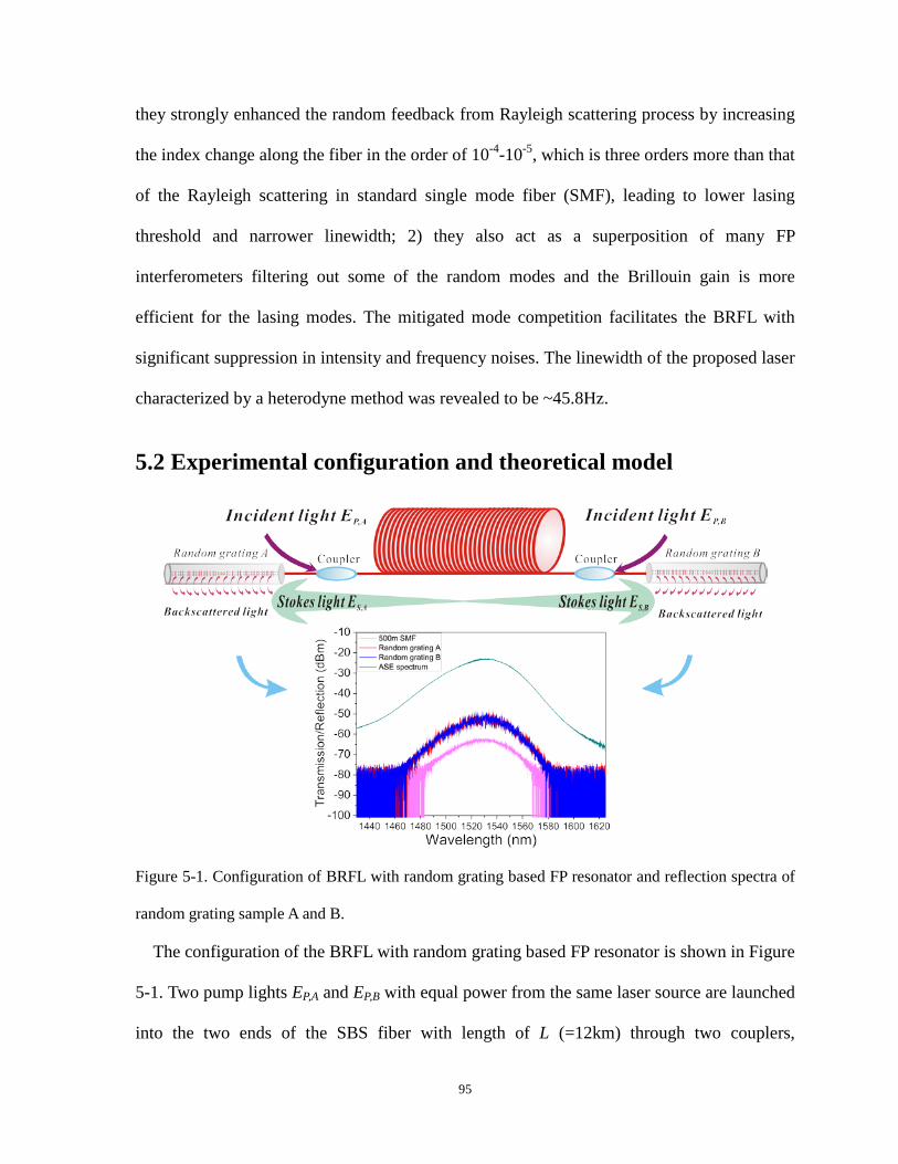
they strongly enhanced the random feedback from Rayleigh scattering process by increasing
the index change along the fiber in the order of 10-4-10-5, which is three orders more than that
of the Rayleigh scattering in standard single mode fiber (SMF), leading to lower lasing
threshold and narrower linewidth; 2) they also act as a superposition of many FP
interferometers filtering out some of the random modes and the Brillouin gain is more
efficient for the lasing modes. The mitigated mode competition facilitates the BRFL with
significant suppression in intensity and frequency noises. The linewidth of the proposed laser
characterized by a heterodyne method was revealed to be ~45.8Hz.
5.2 Experimental configuration and theoretical model
Figure 5-1. Configuration of BRFL with random grating based FP resonator and reflection spectra of
random grating sample A and B.
The configuration of the BRFL with random grating based FP resonator is shown in Figure
5-1. Two pump lights EP,A and EP,B with equal power from the same laser source are launched
into the two ends of the SBS fiber with length of L (=12km) through two couplers,
95

respectively. Once the threshold of the SBS is reached, the SBS process takes place in both
directions. Pump depletion effect will be triggered when the pump power is sufficiently high.
Without random gratings, Rayleigh scattering within the effective amplification length near
both ends of the fiber will provide the random feedback of the Brillouin Stokes light and the
re-captured Stokes light will be re-amplified by the pump from the other side. Thus the fiber
sections within the effective amplification length will act as the random feedback mirrors and
form the random FP resonator [134]. When the two random gratings each with length l
(=10cm) fabricated as described in [136] are inserted at both ends of the SBS fiber through
the coupler as shown in Figure 5-1, the Brillouin Stokes light at both ends of the SBS fiber
will be not only reflected through the Rayleigh scattering by the two fiber sections but also
reflected by the inserted random gratings. The bottom spectra in Figure 5-1 present a
comparison between the reflection spectra of the two random grating samples and 500m
SMF, which corresponds to the total effective amplification lengths in our previous work. It
is illustrated that the reflection spectra for both random grating samples have been enhanced
by more than 10dB compared with the 500m SMF. Thus the random feedback induced by the
random grating pair would dominate over the Rayleigh scattering by the fiber sections. In the
random grating based FP resonator, around 50000 scattering centers from the random grating
samples at each end of the SBS fiber constitute numerous cavity modes within the resonator.
These scattering centers induced by the fs laser that are discretely distributed along each
10cm modified SMF. The randomness of these cavity modes come from the random
variation in the spacing between the neighboring scattering centers ranging from 0 to 3.5μm.
Furthermore, the random variation in the optical path length for each round-trip also
contributes to the randomness of the lasing modes even through Rayleigh scattering centers
are much denser, however, the random grating has stronger reflection and hence higher Q-
96

values for the laser than that from the Rayleigh scattering alone competing for the Brillouin
gain.
The index modification spots in the random grating could be considered as frozen
scattering centers whose feedback amplitudes and locations are randomly distributed along
the grating length. The backscattered Stokes light at the input end of the random grating is
the summation of all the scattered lights from different scattering centers that provide
effective random feedback of the random gratings. The Brillouin Stokes light in one round
trip inside the random grating based FP resonator experiences twice of the scattering
processes by the two random grating samples and twice of the gain processes by the two
input pumps. Therefore, the optical field emitted from the output port could be written as Eq.
(5.1):
ay, ay,
' '
, ,
2 2 /, ,, ,
1 1
4 / 4 /, ,, ,
1 1
,
,
R i R i
A BA j B j
km L i fnL cout B i B iS A i A i
k iN N
i nfz c i nfz cB i B jA i A j
j j
E E e R G R G e
R A e R A e
α π
π π
− −
= =
− −
= =
=
= =
∑ ∏
∑ ∑ (5.1)
where ES is the Brillouin Stokes light; LRay,i is the optical path length of ith round-trip, which
is not a constant value and follows a random process statistically with the estimated value L0
equal to 2L+2l and the estimated standard deviation σL equal to the total length of the two
random gratings 2l; m is the possible number of round-trips; α and n are the mean loss
coefficient and refractive index, respectively; GA,i and GB,i are the SBS amplification
coefficients for ith round trip provided by the two pump lights, respectively; RA,i and RB,i are
the effective feedback factors associated with random grating sample A and B, respectively;
AA,j, AB,j and zA,j, zB,j are the effective reflection amplitudes and locations of the NA’ and NB’
scattering centers that provide effective random feedback in each of the two random gratings,
respectively; f is the optical frequency; and c is the speed of light in vacuum.
97

5.3 Experimental results
Figure 5-2. Experimental setup of the BRFL with random grating based FP resonator; heterodyne
method for linewidth characterization when Part A is replaced by Part B.
The experimental setup of the proposed BRFL is presented in the upper part of Figure 5-2.
Light from a fiber laser with 3.5 kHz linewidth (Rock Module, NP Photonics) was amplified
by an Er-doped fiber amplifier (EDFA). An isolator is placed after the EDFA to avoid the
damage induced by the backflow of the light waves. The amplified pump light was then split
into two equal parts through a 50/50 coupler, which were then launched into each end of a
12km long SMF through another two couplers to build up the bi-direction pumping scheme.
Random grating sample A and B were connected to the two ends of the 12km SMF through
couplers. The 12km SMF as well as the two random gratings were placed inside a
soundproof box in order to be isolated from external disturbances. A narrow optical filter
(~3GHz) was used to remove the un-depleted pump light from the output of the circulator
and make sure pure Stokes lasing output.
98
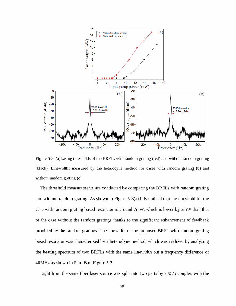
Figure 5-3. (a)Lasing thresholds of the BRFLs with random grating (red) and without random grating
(black); Linewidths measured by the heterodyne method for cases with random grating (b) and
without random grating (c).
The threshold measurements are conducted by comparing the BRFLs with random grating
and without random grating. As shown in Figure 5-3(a) it is noticed that the threshold for the
case with random grating based resonator is around 7mW, which is lower by 3mW than that
of the case without the random gratings thanks to the significant enhancement of feedback
provided by the random gratings. The linewidth of the proposed BRFL with random grating
based resonator was characterized by a heterodyne method, which was realized by analyzing
the beating spectrum of two BRFLs with the same linewidth but a frequency difference of
40MHz as shown in Part. B of Figure 5-2.
Light from the same fiber laser source was split into two parts by a 95/5 coupler, with the
99

smaller part sent through an acousto-optic modulator (AOM) with a frequency downshift of
40MHz and the larger part sent to a 100km delay fiber in order to make them uncorrelated.
The powers of the transmitted lights in the two arms are adjusted to be approximately equal
before being combined and sent to an EDFA. The amplified mixed lights were then launched
into the 12km SBS fiber by replacing Part A with Part B in Figure 5-2 and two BRFLs with a
frequency difference of 40MHz were generated. Thus the output from the optical filter is the
beat signal between the two BRFLs centered at 40MHz. It is also noted that due to (i) the
inhomogeneous broadening of the gain spectra along the SBS fiber induced by the material
nonuniformity and inevitable vibration and temperature fluctuations that could interrupt the
Brillouin gain spectrum of the SBS fiber and (ii) the time-dependent variations in the cavity
length for each round-trip induced by the random distribution of the scattering centers of the
random gratings, the location of the resonant lasing spike of each BRFL would be randomly
distributed within the unflattened Brillouin gain profile at temporal frequency regions where
the Brillouin gain surpasses the total cavity loss. Consequently, the beat signal from the two
BRFLs was not always exactly located at 40MHz, but kept drifting around 40MHz in a range
of about 10MHz, which is within the bandwidth of the Brillouin gain spectrum. In order to
characterize the beat signal information, attempts have been made to capture the beat signal
within a narrow frequency span in an electrical spectral analyzer (ESA) with a high
frequency resolution of 50Hz. Figure 5-3(b)&(c) show the captured beat signals for the
BRFLs with random gratings and without random gratings. The contrasts for both cases are
approximately 50dB and 40dB, respectively. It is illustrated that the 20-dB linewidths for
both cases are measured to be 0.92±0.10 kHz and 1.33±0.12 kHz, which correspond to
46.0±5.0 Hz and 66.5±6.0 Hz for 3-dB linewidth, respectively. Such narrow linewidths could
be explained according to ref. [137]: i the threshold for the Brillouin oscillation with weak
100
external feedback is much lower than that of the single-beam SBS. When the net gain is
close to the threshold of the Brillouin oscillation, the Brillouin spectrum has narrowed
considerably and more dramatically in the case of longer SBS length. In the Brillouin
random fiber lasers with either Rayleigh backscattering fiber based resonator or random
grating based resonator, the gain is provided by the Brillouin gain from the 12km long SBS
fiber, which could be as large as 60-80dB when 15mW pump is launched with different
external feedback. Although the Rayleigh scattering from the two fiber sections only
provides about -40dB feedback over 12km fiber, the unique bi-pump scheme is able to
compensate this loss by amplifying the Brillouin Stokes light generated by one pump with
the other pump within one round-trip. Therefore, the feedback within the resonator is
sufficiently high to compensate the loss leading to a high Q value of the random laser and
narrow linewidth output [134]. With the random grating based resonator, the feedback is
further improved, which results in the increased net gain and narrower linewidth of the
BRFL. The delayed self-heterodyne method in the previous work [134] is not used here as
the instantaneous linewidth information of the proposed BRFL would be deteriorated by the
long delay time introduced by the 250km delay fiber, which results in a time averaged
envelope for many random lasing modes measured from the beat spectrum over the delay
time.
101

Figure 5-4. RIN of the BRFLs with random grating (green) and without random grating (blue) and
the reference fiber laser (red).
The relative intensity noise (RIN) was measured by recording the laser emission with a
photo-detector (PDB130C, Thorlabs) of bandwidth from DC to 350MHz connected to an
oscilloscope (WaveRunner 64Xi-A, Teledyne LeCroy) and calculating the power fluctuation
normalized to the average power level. The inset of Figure 5-4 gives an example of time
domain signal of the proposed BRFL output. The constant time domain series indicates the
single longitudinal mode operation of the BRFL in the given time period. For comparison,
the RIN of the BRFLs with and without random gratings and the commercial NP photonics
fiber laser were measured, respectively. It is noted that the RIN of the BRFL with random
gratings in the high frequency region beyond MHz is higher than the value of the NP
photonics fiber laser but much lower than that of the BRFL without random gratings. This is
attributed to the significant decrease in the number of longitudinal modes supported by the
102

random grating. In the configuration of the BRFL without random grating, the Rayleigh
scattering within the effective amplification lengths on both ends of the SBS fiber plays the
dominant role in random feedback. Numerous Rayleigh scattering centers with very short
and irregular intervals at both sides form a huge number of FP resonators with randomly
varying cavity lengths, which leads to a high density of mode numbers within the Brillouin
gain bandwidth. Thus the mode competitions and hopping are intensified, leading to high
intensity noise. While in the case with random grating based resonator, the number of the
index modification spots induced by the femtosecond laser is about 50000, which are
discretely distributed along the modified 10cm long SMF. The randomness comes from the
random variation between the neighboring modification spots ranging from 0 to 3.5μm.
However, the discrete mode structure of the random grating renders fewer randomly
distributed scattering centers compared to that of the Rayleigh scattering in SMF, which
results in fewer random modes for lasing and thus lower mode density. Therefore, in the
BRFL with random grating based resonator, the mode hopping effect within the Brillouin
gain bandwidth induced by the mode competition is largely suppressed. It is also noticed that
the proposed BRFL shows higher RIN than that of the NP photonics fiber laser in the low
frequency range. The BRFL with random grating feedback has a higher sensitivity to the
external disturbances such as temperature fluctuations, mechanical vibrations, and acoustic
waves, which gives rise to the drift of Brillouin gain spectrum and cavity length fluctuations
of the formed random FP resonators at low frequencies, when compared with the NP
photonics fiber laser that has included RIN suppression mechanism by temperature control
and electronic feedback.
103

Figure 5-5. Frequency noise spectra of the BRFLs with random grating (green) and without random
grating (blue) and the reference fiber laser (red).
The frequency noise measurements were performed with an imbalanced symmetric 3×3
coupler Michelson interferometer, which converts optical frequency fluctuation of the
measured lasers into amplitude fluctuation. To ensure that the amplitude fluctuation
dominates over all other noises, the imbalance of the interferometer is made sufficiently large
by inserting a delay fiber of 4km long into one arm [97]. Two photo-detectors were used to
receive the interferometric signals from the two output ports of the interferometer and the
recorded data were sent into the Differential-Cross-Multiplication Algorithm [138] at a
bandwidth of 100 kHz to extract the phase information of the fiber interferometer.
Using the phase demodulation scheme, the frequency noise spectra of the BRFLs with
random grating and without random grating, and the NP Photonics fiber laser were obtained
from the interferometric signals, respectively as shown in Figure 5-5. The frequency noise
104

levels for the BRFLs both surpass that of the reference fiber laser in the low frequency range
around hundreds of Hz. The main factors contributing to the higher frequency noise in low
frequency domain are the external disturbance induced instability of the cavity length of the
FP resonator in the BRFL and the temperature fluctuation induced Brillouin gain drift. Firstly,
in the case of the proposed BRFL with resonators formed either by Rayleigh scattering
centers or by femtosecond laser induced scattering centers, the resonator mirrors are both
randomly distributed within a finite length, which are more easily perturbed by external
disturbances in the lab environment compared with the conventional fiber lasers with only
two mirrors. The induced randomly varied cavity length of the BRFL modifies the mode
structure significantly along the time, which makes the resonance frequency keep changing.
Lacking mode stabilization mechanism makes the proposed BRFL suffering higher
frequency noise at low frequency range below 0.5 kHz. Secondly, the thermally fluctuating
effective refractive index associated with the pump light in the BRFL induced by the
surrounding temperature variations compels the Brillouin gain spectrum drifting in a low
frequency manner, which is bound to contribute to the frequency noise of the BRFL. It is
interesting to note that the BRFL with random gating shows a lower frequency noise than
that of the BRFL without the random grating owing to a more compact random grating based
resonating cavity which is less sensitive to the external perturbations. Thanks to the long
cavity length and randomly distributed feedback in the BRFL, the thermal-induced frequency
noise which shows 1/f1/2 shape in the frequency noise spectrum for the reference fiber laser is
largely suppressed [97, 139, 140]. Meanwhile, the phase matching prerequisite imposed by
the pump and Stokes waves through the whole lasing process of the BRFL also contributes to
the lower frequency noise level in frequency range beyond 0.5 kHz.
105

5.4 Conclusion
In summary, a novel BRFL constructed by the random grating based FP resonator is
proposed and experimentally realized. Comparisons have been made between the proposed
BRFL scheme and the previous scheme. The strengthened random feedback from the fs laser
fabricated random gratings increases the lasing efficiency and narrows linewidth of lasing
spike. With significant suppression in intensity noise and improvement in frequency noise,
the proposed BRFL will pave the way for applications in high resolution spectrometers,
coherent light sources and optical sensing.
106
Chapter 6 Multi-parameter sensor
based on EDF random fiber lasers
with fiber random grating feedback
This chapter presents a novel concept of utilizing erbium-doped fiber random fiber lasers
(EDFRLs) to achieve multi-parameter sensing. The experimental configuration, theoretical
model, and application of multi-parameter sensing of the EDFRL are described in details.
The proposed random fiber ring laser consists of an EDF as the gain medium and a fiber
random grating as the feedback medium. The random feedback is effectively realized by a
large number of reflections from around 50000 femtosecond (fs) laser induced refractive
index modulation regions over a 10cm standard single mode fiber. Numerous polarization-
dependent spectral filters are formed and superimposed to provide multiple lasing lines with
high signal-to-noise ratio up to 40dB, which gives an access for a high-fidelity multi-
parameter sensing scheme. The number of sensing parameters can be controlled by the
number of the lasing lines via input polarizations and wavelength shifts of each peak can be
explored for the simultaneous multi-parameter sensing with one sensing probe. In addition,
the random grating induced coupling between core and cladding modes can be potentially
used for liquid medical sample sensing in medical diagnostics, biology and remote sensing in
hostile environments. Section 6.1 gives the background of random fiber lasers and their
applications. Section 6.2 introduces the experimental configuration and theoretical model of
the EDFRL. Section 6.3 shows the experimental realization of the multi-parameter sensing
using the EDFRL. Section 6.4 draws the final conclusion.
107

6.1 Introduction
In optical materials that appear opaque, multiple scattering usually takes place thousands
of times in a random fashion for the penetrated light rays before they exit. Based on this type
of propagation randomness, random lasers have been extensively studied and researched
since the first time the laser action was obtained in disordered structures as proposed by
Ambartsumyan, etc. in 1966 [15]. Over the past several decades, random lasers have been
observed and demonstrated in various random media [17, 19, 25, 110, 112, 113, 141-143],
including crystal powder material, laser dye with nanoparticles, rare-earth powders,
semiconductor powder, polymer films with silver nanoparticles and even dye treated human
tissues. The unique emission spectra and cost-effective features of random lasers make
themselves excellent candidates in applications of environment lighting [144], remote
sensing [145], speckle-free imaging [146], document coding [111], and medical diagnostics
[25, 147]. The directionality and lasing efficiency of random lasers could be improved and
optimized by replacing the disordered medium with optical fibers, namely the random fiber
laser. The 1-D optical fiber waveguide provides good confinement in the transverse
directions of the light rays trapped inside and effective one-dimension random feedback.
RFLs have been realized using Er-doped fiber gain, Raman gain, and Brillouin gain with
random feedback induced by Rayleigh scattering [27, 72, 102, 128, 134, 148], or artificially
induced randomness such as a photonic crystal fiber filled with a suspension structure [68],
Bragg gratings in rare-earth doped fiber [47], and polymer optical fiber [149]. Either in-
coherent or coherent lasing outputs have been observed in these random lasing systems, with
lasing spectra of bell-shaped peaks as broad as terahertz level [26] or even narrow spikes as
sharp as sub-kilohertz [87, 88]. Random fiber lasers based on the Raman gain has been
108

widely used in many fields, including providing the distributed Raman amplification with
lower effective noise and good stability in telecommunication applications [101, 127],
remote temperature point-based sensing systems up to 300km [102, 150], and extending the
sensing range in the distributed sensing systems [105, 151]. The Brillouin gain based random
fiber laser has been utilized in spectral characterization for lasing linewidth measurements
[134] as well as random bit generation [135].
In this chapter, a multi-parameter sensor based on the random fiber laser composed of a
fiber ring laser with EDF gain and an injection of a fiber random grating is proposed and
experimentally demonstrated. The fiber random grating consisting of around 50000 index
modification spots induced by fs laser with a randomly varying separation in the scale of
several microns provides highly disordered scattering feedback, which could be amplified by
the Er-doped gain with wide bandwidth. The resultant sub-nanometer sharp spectral peaks
associated with high-Q resonances are utilized for multi-parameter sensing. By controlling
the polarization state of the light to be scattered by the random grating, selective modes
could be amplified as a result of lasing lines with wide spectral separations. Different from
fixed cavity laser that can only support one peak or multiple peaks with integer numbers of
longitudinal modes, these multiple lasing lines are contributed by the multiple random modes
which originate from different Fabry-Perot (FP) cavities formed by the scattering centers
along the random grating sample. Furthermore the randomly distributed refractive index
modification spots introduce random birefringence along the sample, making the FP filters
polarization dependent. Hence the lasing lines have different strain and temperature
dependence due to different index modifications as well as dispersion effects. With the sharp
peaks of high-Q value in the RFL, simultaneous multi-parameter measurements could be
realized with better resolution compared with the single-pass random grating sensor [136]. In
109
a previous work where a Raman random fiber laser with multiple lasing lines was achieved
based on multiple fiber Bragg gratings (FBG) and Rayleigh feedback from a 22km long
optical fiber [81]. Each lasing line is potentially able to be used for sensing depending on the
temperature response of the FBG reflectors. However, the proposed random fiber laser based
sensor possesses more advantages over the previous scheme such as same sensing head for
multi-parameter sensing, higher SNR of the lasing lines, simple and cost-effective fabrication
process without the need of phase mask or critical alignment and vibration control in the
FBG manufacturing process, higher compactness and lower power consumption.
6.2 Experimental configuration and theoretical model
The experimental setup for the fiber random grating based EDF ring laser is shown in Fig.
6-1. A C-band Erbium-doped fiber amplifier (EDFA) ranging from 1528nm to 1565nm was
used as the laser seed and gain medium. The amplified spontaneous emission (ASE) from the
EDFA then passed through the isolator and the first polarization controller (PC 1). The
isolator was placed next to the EDFA to avoid the damage induced by the backflow of the
lasing light and the PC 1 was used to adjust the input polarization of the light before it was
sent to the random grating sample through an optical circulator. The enlarged figure shows a
schematic drawing of the light scattering in the random grating. The randomly backscattered
light from the random grating was guided to another PC followed by an optical coupler with
a ratio of 95/5. 95% of the light was sent back to the ring resonator, while 5% was used for
detection.
110
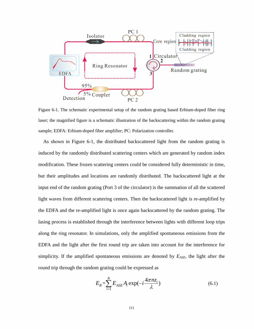
Figure 6-1. The schematic experimental setup of the random grating based Erbium-doped fiber ring
laser; the magnified figure is a schematic illustration of the backscattering within the random grating
sample; EDFA: Erbium-doped fiber amplifier; PC: Polarization controller.
As shown in Figure 6-1, the distributed backscattered light from the random grating is
induced by the randomly distributed scattering centers which are generated by random index
modification. These frozen scattering centers could be considered fully deterministic in time,
but their amplitudes and locations are randomly distributed. The backscattered light at the
input end of the random grating (Port 3 of the circulator) is the summation of all the scattered
light waves from different scattering centers. Then the backscattered light is re-amplified by
the EDFA and the re-amplified light is once again backscattered by the random grating. The
lasing process is established through the interference between lights with different loop trips
along the ring resonator. In simulations, only the amplified spontaneous emissions from the
EDFA and the light after the first round trip are taken into account for the interference for
simplicity. If the amplified spontaneous emissions are denoted by EASE, the light after the
round trip through the random grating could be expressed as
1
4= exp( )N
iiR ASE
i
nzE E A i πλ=
−∑ (6.1)
111
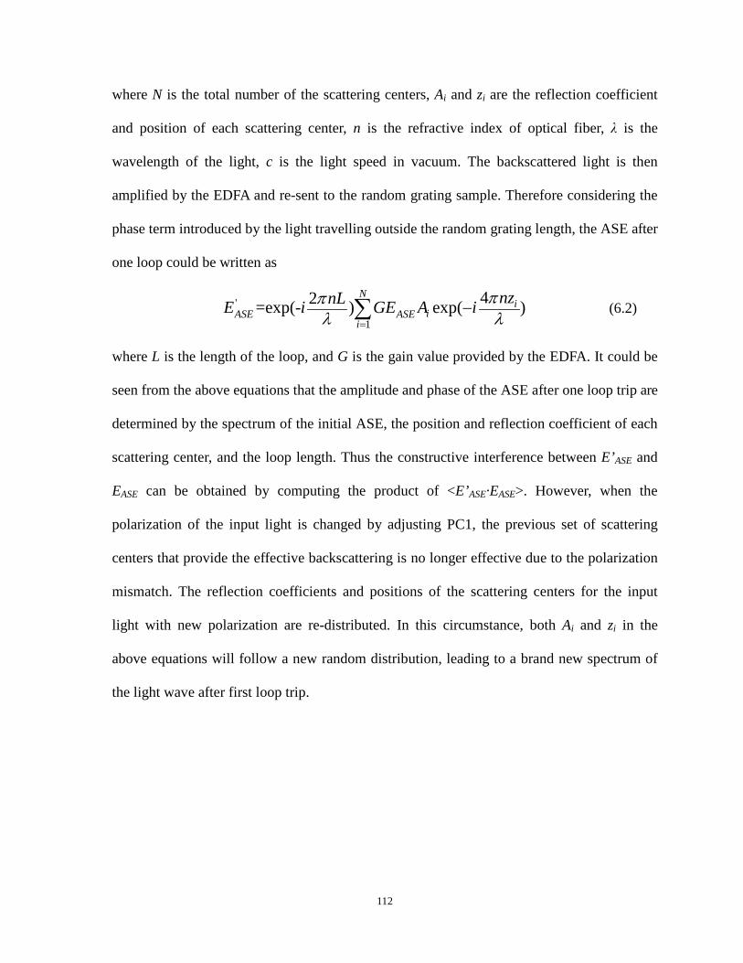
where N is the total number of the scattering centers, Ai and zi are the reflection coefficient
and position of each scattering center, n is the refractive index of optical fiber, λ is the
wavelength of the light, c is the light speed in vacuum. The backscattered light is then
amplified by the EDFA and re-sent to the random grating sample. Therefore considering the
phase term introduced by the light travelling outside the random grating length, the ASE after
one loop could be written as
'
1
42=exp(- ) exp( )N
iiASE ASE
i
nznLE i GE A i ππλ λ=
−∑ (6.2)
where L is the length of the loop, and G is the gain value provided by the EDFA. It could be
seen from the above equations that the amplitude and phase of the ASE after one loop trip are
determined by the spectrum of the initial ASE, the position and reflection coefficient of each
scattering center, and the loop length. Thus the constructive interference between E’ASE and
EASE can be obtained by computing the product of <E’ASE·EASE>. However, when the
polarization of the input light is changed by adjusting PC1, the previous set of scattering
centers that provide the effective backscattering is no longer effective due to the polarization
mismatch. The reflection coefficients and positions of the scattering centers for the input
light with new polarization are re-distributed. In this circumstance, both Ai and zi in the
above equations will follow a new random distribution, leading to a brand new spectrum of
the light wave after first loop trip.
112
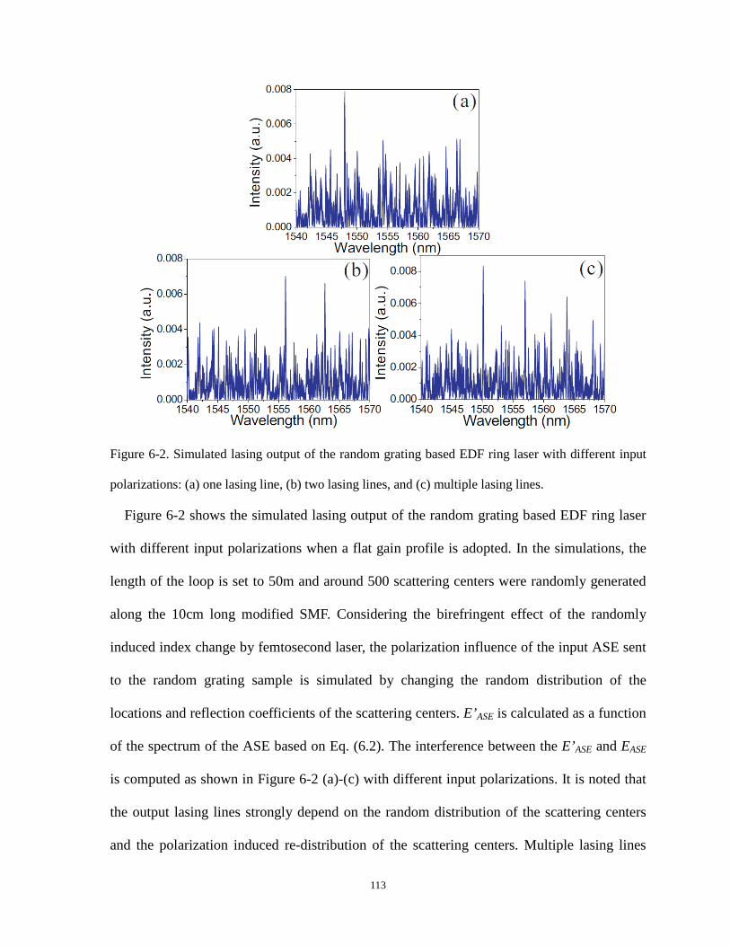
Figure 6-2. Simulated lasing output of the random grating based EDF ring laser with different input
polarizations: (a) one lasing line, (b) two lasing lines, and (c) multiple lasing lines.
Figure 6-2 shows the simulated lasing output of the random grating based EDF ring laser
with different input polarizations when a flat gain profile is adopted. In the simulations, the
length of the loop is set to 50m and around 500 scattering centers were randomly generated
along the 10cm long modified SMF. Considering the birefringent effect of the randomly
induced index change by femtosecond laser, the polarization influence of the input ASE sent
to the random grating sample is simulated by changing the random distribution of the
locations and reflection coefficients of the scattering centers. E’ASE is calculated as a function
of the spectrum of the ASE based on Eq. (6.2). The interference between the E’ASE and EASE
is computed as shown in Figure 6-2 (a)-(c) with different input polarizations. It is noted that
the output lasing lines strongly depend on the random distribution of the scattering centers
and the polarization induced re-distribution of the scattering centers. Multiple lasing lines
113

with large spectral separations could be observed as a result of multiple resonances of the
constructive interference between E’ASE and EASE. Due to the strong mode competitions
among these resonant modes induced by the flat gain profile, the contrasts of the resonant
modes are comparable and their values are limited compared with the noisy background
resonances. As will be shown later, when an unflattened gain profile, i.e. EDF gain, is
applied instead, the resonant lasing modes will preferably appear at spectral regions where
the gain overcomes loss with high contrasts.
6.3 Experimental results
Figure 6-3. (a) Lasing thresholds indicated by the laser output power as a function of pump current
for different numbers of emitted lasing lines. Experimental results of the lasing spectra with different
input polarizations: (b) one lasing line, (c) two lasing lines, and (d) three lasing lines.
114

In the experiments, the random grating sample was placed in an aluminous soundproof
box to protect the backscattering light from the environmental disturbances. The output
power of the EDFA was gradually increased to reach the threshold and activate the ring laser.
A portion of the ring laser output from the 5% port of the coupler was sent to an Optical
Spectral Analyzer (OSA) for spectrum characterization. The polarization of the input light
was adjusted by controlling the PC1. The laser output powers as the function of the EDFA
current were plotted in Figure 6-3(a) with different input polarization states. Figure 6-3(b)-(d)
show the corresponding measured lasing spectra of the random grating based fiber ring laser
with different numbers of lasing lines. The EDFA currents for all cases were set above the
threshold values. By changing the input polarization state of the ASE to the random grating
sample, the outcome lasing spectra respond with different numbers of lasing lines associated
with different random modes. The randomly distributed scattering centers induced by the
femtosecond laser micro-machining introduce random birefringence along the fiber and form
numerous polarization dependent spectral filters which are superimposed with each other,
leading to specific coherent resonant lasing lines. The threshold for more lasing lines has a
tendency to decrease. It is also notified that the resonant lasing lines are built up with very
high signal-to-noise ratio up to 40dB, which is limited by the gain provided by the EDFA.
The separation of these lasing lines could be as large as about 19nm, which is due to the
spectral filtering effect of the FP filters formed by the closely separate scattering centers, that
is, the resonant wavelength is selected by the polarization-dependent filters. Because of
different spacing among the index modification spots, multiple lasing lines selected by
different FP cavities have different strain and temperature dependence due to different index
modulations at different locations, which gives access to the parameter measurement using
the RFL imposed by the random grating feature.
115

Figure 6-4. (a) Illustration of lasing line shifts as a result of temperature change; wavelength shift
calibration results of temperature and strain measurements for Line 1(b) and Line 2 (c).
The wavelength responses of the multiple lasing lines could be utilized for measuring
parameters which influence the phase differences of those FP filters formed along the
random grating sample. The phase changes are different for FP cavities at different locations
and also impacted by external disturbances with different extents at different wavelengths,
leading to distinct wavelength shifts among the resultant multiple lasing lines. In experiments,
temperature measurements were conducted by placing the random grating sample into an
oven. The output lasing spectra at each temperature were recorded when the temperature
inside the oven remained stable. To characterize the strain sensitivity of the proposed sensor,
the two ends of the random grating were anchored horizontally between a motorized
translational stage and a stationary stage. The system is capable of stretching the sensor
116

longitudinally by controlling the motorized stage along the axis of the random grating with a
sequential strain step of 100 με. As shown in Figure 6-4(a), two lasing lines at 1545.4nm and
1564.4nm are selected for monitoring the spectral shifts responding to the temperature and
strain variations. It could be seen from the figure that both lines experience significant
spectral shifts when the surrounding temperature of the random grating was increased from
28oC to 77oC. It was also noticed that in the experiments the variation in the peak intensities
of the lasing lines and generation of extra lasing lines were observed when relatively high
temperature or large strain was applied on the sensor. However, if the external disturbances
are not so large that the induced refractive index change is quite small compared to the
femtosecond laser induced refractive index modification which is in the order of 10-4~10-5 in
the random grating, the target lasing lines still remain there for the spectral shift monitoring.
More details of the temperature and strain measurements are depicted in Figure 6-4(b)(c), in
which the wavelength shift-related temperature coefficients for both lasing lines are
10.0pm/oC and 10.4pm/oC and the wavelength shift-related strain coefficients for both lasing
lines are 1.60pm/με and 1.53pm/με, respectively.
A character matrix MT,ϵ is defined to represent the sensing performance of the lasing lines
in the random grating based fiber ring laser by
1 1 1,
2 2 2
10.0 1.60=10.4 1.53
T
T TC CT T TMC C
ε
ε ε
λε ε ελ
∆ ∆ ∆ ∆= =
∆ ∆ ∆∆ (6.3)
where Δλ1 and Δλ2 represent the spectral shift of Line 1 and 2 induced by temperature and
strain variations. C1T, C1
ε, C2T, and C2
ε are the temperature and strain coefficients of Line 1
and 2, respectively. The character matrix MT,ϵ can be used to simultaneously determine the
variations in the temperature and strain from the spectral shifts of lasing lines. Error analysis
117
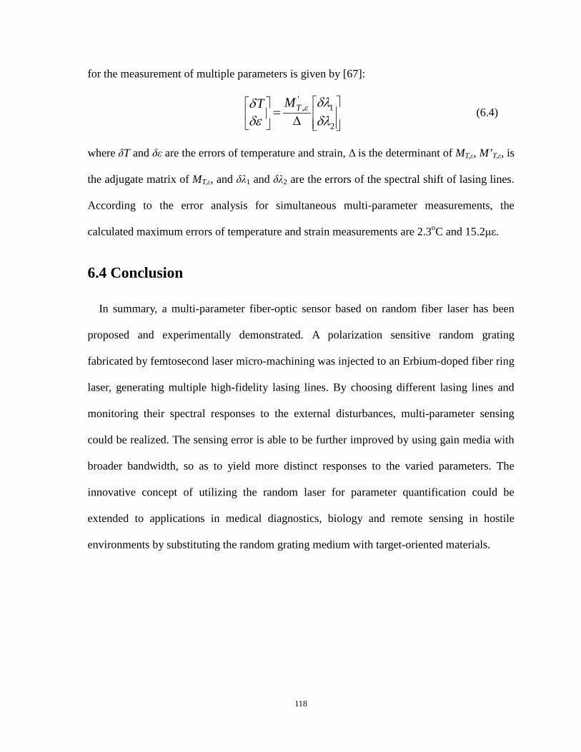
for the measurement of multiple parameters is given by [67]:
'
, 1
2
TMT ε δλδδε δλ
=∆
(6.4)
where δT and δε are the errors of temperature and strain, Δ is the determinant of MT,ε, M’T,ε, is
the adjugate matrix of MT,ε, and δλ1 and δλ2 are the errors of the spectral shift of lasing lines.
According to the error analysis for simultaneous multi-parameter measurements, the
calculated maximum errors of temperature and strain measurements are 2.3oC and 15.2με.
6.4 Conclusion
In summary, a multi-parameter fiber-optic sensor based on random fiber laser has been
proposed and experimentally demonstrated. A polarization sensitive random grating
fabricated by femtosecond laser micro-machining was injected to an Erbium-doped fiber ring
laser, generating multiple high-fidelity lasing lines. By choosing different lasing lines and
monitoring their spectral responses to the external disturbances, multi-parameter sensing
could be realized. The sensing error is able to be further improved by using gain media with
broader bandwidth, so as to yield more distinct responses to the varied parameters. The
innovative concept of utilizing the random laser for parameter quantification could be
extended to applications in medical diagnostics, biology and remote sensing in hostile
environments by substituting the random grating medium with target-oriented materials.
118

Chapter 7 Highly sensitive fiber
random grating based EDF random
fiber laser sensor for ultrasound
detection
This chapter presents a novel fiber random grating based EDF random fiber laser for
highly sensitive ultrasound detection. The configuration of the random fiber laser sensor,
lasing characteristics, and ultrasound detection results are described in details. The random
fiber laser is constructed with the EDF gain. A fiber random grating provides random
distributed feedback for the random laser and acts as an ultrasound sensing head. The
random laser can operate in a single-mode lasing scenario, which offers linear and pure
temporal responses to the broadband ultrasonic acoustic emission from 20kHz to 0.8MHz.
The multiple interfering reflection spectrum of the random grating provides large number of
steep peak areas over a broad spectral range, which significantly enhances the sensitivity of
the random laser sensor and makes it an ideal sensor in harsh environment with large
temperature or strain variations. The proposed laser sensor offers signal-to-noise ratio
improvement up to 20dB and higher sensitivity compared with conventional piezoelectric
acoustic sensors. Section 7.1 gives the background of ultrasound detection using fiber-optic
techniques. Section 7.2 introduces the experimental configuration and operation principle of
the EDF random fiber laser sensor. Section 7.3 shows the experimental results of the
ultrasound detection. Section 7.4 draws the final conclusion.
119

7.1 Introduction
Ultrasound detection is a vital and versatile technique, which has been widely researched
and utilized in varieties of areas such as structural health monitoring, geophysical exploration,
dimensional measurement, material testing, and biomedicine [152-156]. One phenomenal
process that generates the ultrasonic waves is the acoustic emission, which is frequently
accompanied by damage-related structural changes and gives rise to the release of elastic
waves with typical frequency range between 100kHz and 1MHz and strain in the sub-
micron/m range [157]. Thus an effective ultrasonic acoustic emission sensor with capabilities
of broad bandwidth inspection and high sensitivity is highly desired.
Fiber-optic technique based ultrasound sensors have been extensively investigated and
applied with significant advantages, such as immunity to electromagnetic interference,
compact footprint, durability, and multiplexing capability over the conventional
piezoelectricity based ultrasonic probes. Fiber Bragg gratings (FBGs) are the most
commonly used sensing elements in the fiber-optic ultrasound sensors [158-162]. The most
straightforward demodulation of the responses of the FBG to the ultrasound is to detect the
power of the reflected light from the gratings [163-167]. However, the ultrasound sensors
based on the regular FBGs usually suffer from the broad bandwidths of the regular FBGs,
which force the sensitivity of the sensor to depend on the slight wavelength dependency of
the intensity of the broadband light source [163, 164]. Although the phase-shifted FBG (PS-
FBG) has been utilized to realize the ultrasound detection in megahertz [165-167], the
narrow peak in the PS-FBG lacks the stability for demodulation due to the environmental
change, which requires extra complex configurations such as Pound-Drever-Hall method for
stabilization. This problem was solved in [168], but the proposed coherence-restored pulse
120

interferometry may lack the high sensitivity for ultrasound signals below 4MHz and
simplicity due to the relatively complex demodulation schemes. It has been demonstrated
that constructing an erbium fiber ring laser (EFRL) incorporated with fiber gratings is able to
improve the ultrasound sensitivity owing to the significant power enhancement in the laser
ring cavity [169]. However, the relative flat amplified spontaneous emission (ASE) profile of
the erbium doped fiber (EDF) and the multi-mode lasing scenario lead to noisy temporal
responses, which limit the sensitivity of the laser sensor and the maximum detectable
frequency to tens of kilohertz. To solve the problem, a tunable filter is adopted to select the
lasing wavelength at the maximum spectral slope region of the Bragg spectrum in order to
increase the sensitivity [170], whereas the sensing system does not have high temperature or
strain robustness and has limited detectable ultrasound frequency up to 200kHz because of
the multi-mode lasing operation. PS-FBG is also incorporated into the EFRL acting as the
sensing head, which allows single-longitudinal mode lasing and achieves highly sensitive
ultrasound detection utilizing the spectral slope of the reflection spectrum of an apodized
FBG (AFBG) [171]. However, this laser sensor is not applicable in harsh environments with
high temperature and large strain changes, which may shift the narrow band dip of the PS-
FBG out of the reflection spectrum of AFBG and remarkably reduces the sensitivity. The
PS-FBG was also used to achieve the polarimetric heterodyning fiber grating laser for
ultrasonic detection up to megahertz range [162], however, it lacks high sensitivity in
detecting kilo-hertz ultrasound waves due to small birefringence variations induced by the
large wavelength acoustic waves.
In this chapter, we present a highly sensitive fiber-optic ultrasound sensor based on the
random fiber laser. A fiber random grating is used to provide random distributed feedback for
the EFRL and for the first time utilized as the ultrasound sensing head. The effective
121

suppression of cavity modes owing to the random grating enables the laser sensor with linear
response to the ultrasonic acoustic waves over broad frequency range and the multiple
interfering reflection spectrum from the random period grating equips the sensor with
tremendous number of steep peak areas, by which the sensing system, with high probability,
has a lasing mode at a steep region of the reflection spectrum where the sensitivity is the
greatest. Thus the random grating eases the setting of the system to its working point and
guarantees ultrasound detection with high sensitivity over a broad operating spectral range.
The proposed laser sensor exhibits broadband ultrasound response within 0.8MHz frequency
range with high signal-to-noise ratio (SNR) without any locking mechanism, which offers a
simple solution as an ideal sensor in harsh environment with large temperature or strain
changes.
122

7.2 Experimental configuration and operation principle
Figure 7-1. (a) Experimental setup of the fiber random grating based random laser sensor for
ultrasound detection; (b) EDFA gain profile (Black) and reflected power spectrum from fiber random
grating (Red); (c) Reflection spectrum of the fiber random grating; (d) Multi-wavelength lasing
spectrum; (e) Single-wavelength lasing spectrum.
The experimental setup of the proposed fiber random grating based random laser sensor is
shown in Figure 7-1(a). The random fiber laser consists of a C-band erbium-doped fiber
amplifier (EDFA) as the laser seed and gain medium and a fiber random grating providing
random distributed feedback, which is realized by a large number of reflections from around
50000 femtosecond laser induced refractive index modulation regions over a 10cm standard
single mode fiber [136]. The ASE from the EDFA then passes through the first polarization
controller (PC 1) and the optical circulator (OC) to the random grating sample. The random
123

distributed feedback light from the random grating then passes through PC 2 and a coupler
with a ratio of 95/5 and is finally re-amplified by the EDFA. The two PCs are used to adjust
the state of polarization (SOP) of the intra-cavity light in order to achieve polarization
matching and increase lasing efficiency. Figure 7-1(b)&(c) show the ASE profile of the
EDFA and the reflected ASE spectrum from the random grating as well as the subtraction
between the two spectra, i.e. the reflection spectrum of the random grating. It is clearly
illustrated that the relative flat ASE profile of the EDFA is tailored to multiple interfering
spectrum by the random period grating thanks to the superposition of numerous Fabry-Perot
interferometers and Mach-Zehnder interferometers formed by the index modification spots,
which renders tremendous number of large spectral slope regions for the highly sensitive
ultrasound sensing. The proposed random fiber laser is able to lase at multi- or single-
wavelength, depending on the SOP of the intra-cavity light and the birefringent properties of
the random grating sample [172]. An example of multi-wavelength lasing is shown in Figure
7-1(d). In order to realize highly efficient single-wavelength lasing and take advantage of the
multiple interfering spectrum of the random grating for ultrasound sensing, a tunable filter
(TF) with 3GHz bandwidth is inserted into the random fiber laser. Figure 7-1(e) gives an
example of single-wavelength lasing at 1558nm with the help of the TF.
The ultrasound detection was conducted by bonding the two ends of the random grating
sample and the lead zirconate titanate (PZT) actuator onto an aluminum plate with dimension
of 320mm×100mm×7mm as shown in the inset photograph of Figure 7-1(a). The random
grating was located 1cm away from the PZT actuator and kept straight by pre-stretching
during the bonding process. The PZT actuator was driven by a function generator to generate
Rayleigh waves that propagate as the acoustic surface wave along the aluminum plate
considering that the thickness of the plate is comparable to the acoustic wavelength. Since
124
only the two ends of the fiber random grating were glued onto the aluminum plate, the
generated Rayleigh wave in the aluminum plate, consisting of both longitudinal and shear
waves, impinged the random grating in the form of dynamic longitudinal strain. Through the
strain-optic effect, the induced change in the refractive index of the random grating sample
due to the applied longitudinal strain could be expressed as
312 11 12
1 [ ( )]2n n p p pε υ∆ = − − + (7.1)
where ε is the dynamic longitudinal strain; p11 and p12 are optoelastic constants of silica; and
ν is the Poisson ratio of silica. Strictly speaking the random period of the random grating is
also varied in the presence of the acoustic wave through the geometric effect, which,
accompanied with the strain-optic effect, would change the optical path lengths of the many
interferometers formed inside the random grating sample, leading to the spectral shift of the
reflection spectrum. The dynamic strain generated by the PZT actuator in the ultrasonic
frequency range is usually in the order of nano-strain, which leads to the spectral shift in the
order of femto-meter by recalling that the strain sensitivity of the fiber random grating is
around 1.2pm/με [136].
Figure 7-2. Radio frequency spectra of delayed self-heterodyne measurements for lasing output with
mirror feedback (a) and random grating feedback (b).
125
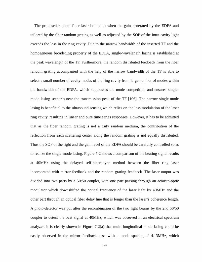
The proposed random fiber laser builds up when the gain generated by the EDFA and
tailored by the fiber random grating as well as adjusted by the SOP of the intra-cavity light
exceeds the loss in the ring cavity. Due to the narrow bandwidth of the inserted TF and the
homogeneous broadening property of the EDFA, single-wavelength lasing is established at
the peak wavelength of the TF. Furthermore, the random distributed feedback from the fiber
random grating accompanied with the help of the narrow bandwidth of the TF is able to
select a small number of cavity modes of the ring cavity from large number of modes within
the bandwidth of the EDFA, which suppresses the mode competition and ensures single-
mode lasing scenario near the transmission peak of the TF [106]. The narrow single-mode
lasing is beneficial to the ultrasound sensing which relies on the loss modulation of the laser
ring cavity, resulting in linear and pure time series responses. However, it has to be admitted
that as the fiber random grating is not a truly random medium, the contribution of the
reflection from each scattering center along the random grating is not equally distributed.
Thus the SOP of the light and the gain level of the EDFA should be carefully controlled so as
to realize the single-mode lasing. Figure 7-2 shows a comparison of the beating signal results
at 40MHz using the delayed self-heterodyne method between the fiber ring laser
incorporated with mirror feedback and the random grating feedback. The laser output was
divided into two parts by a 50/50 coupler, with one part passing through an acousto-optic
modulator which downshifted the optical frequency of the laser light by 40MHz and the
other part through an optical fiber delay line that is longer than the laser’s coherence length.
A photo-detector was put after the recombination of the two light beams by the 2nd 50/50
coupler to detect the beat signal at 40MHz, which was observed in an electrical spectrum
analyzer. It is clearly shown in Figure 7-2(a) that multi-longitudinal mode lasing could be
easily observed in the mirror feedback case with a mode spacing of 4.13MHz, which
126

corresponds to a ring cavity length of 55.5m. The case with random grating feedback
presents a pure single-mode lasing peak with a contrast over 50dB as shown in Figure 7-2(b).
During the ultrasound detection, the lasing output from the 5% port of the 95/5 coupler was
directly detected by a 350MHz photo-detector and the oscillation signals were observed and
recorded by an oscilloscope with a sampling rate of 5MS/s.
The sensing principle of the proposed random fiber laser for ultrasound detection is based
on the loss modulation of the laser ring cavity, where the sensitivity depends on the spectral
slope of the wavelength position selected by the TF in the reflection spectrum of the fiber
random grating. Generally, the strain-optic and geometric effects induced by the ultrasonic
wave would cause the refractive index profile changes along the random grating, leading to
the spectrum shift. Consequently, the output power of the proposed random laser changes
with the shift of the reflection spectrum of the random grating, as the insertion loss from the
random grating is varied. Thanks to the steep spectral slope regions in the reflection
spectrum of the random grating, the achievable sensing sensitivity of the random laser will
be much better than that of the fiber ring laser sensors based on the gain profile of the
broadband light source with less steep spectral slope areas. Furthermore, it has been
demonstrated that the reflection spectrum of the random grating shifts with almost
unchanged shape with variations of temperature in tens of degrees or strain in hundreds of
micro-strains [136], which ensures linear modulation of the cavity loss and results in periodic
temporal responses.
127

Figure 7-3. (a) Normalized reflection spectrum of fiber random grating in the range between 1556nm
and 1568nm; Selected lasing wavelengths at (b) 1558.024nm, (c) 1560.018nm, (d) 1562.014nm, and
(e) 1565.026nm.
The detected output AC signal from the photo-detector has a voltage determined by:
=S SV R SGPλ∆ (7.2)
where VS is the detected AC output voltage, R is the photodetector’s response factor, ΔλS is
the spectral shift caused by the longditudinal strain, S is the spectral slope at the lasing
wavelength, G is the gain provided by the EDFA, and P is the laser power. Since the spectral
shift of the random grating is proportional to the applied strain, which could be expressed as
ΔλS=αε, where α is a constant parameter at a specific lasing wavelength related to refractive
index, optoelastic coefficients, and Poisson’s ratio, the minimum detectable strain is obtained
when the voltages generated by the ultrasonic signal and noise are equal: VS=VN, where the
128

noise output VN includes the intensity and frequency noise of the random laser as well as the
noise from the photo-detector itself and could be determined by measuring the proposed
random laser output without ultrasound wave impact on the random grating. Thus the
minimum detectable strain is obtained as:
min = NVRSGPε
α (7.3)
As could be seen from Eq. (7.3), the minimum detectable strain varies with the spectral slope
of the lasing wavelength provided that other parameters of the laser system remain constant.
Figure 7-3 shows four different wavelengths at 1558.024nm, 1560.018nm, 1562.014nm and
1565.026nm that are selected by the TF for the random lasing in the experiments. The
normalized reflection ratios for each selected lasing wavelength are r=0.51, 0.21, 0.12, and
0.37. The local spectral slopes at these wavelengths are S=5.78nm-1, 0.76nm-1, 2.66nm-1, and
4.89nm-1, corresponding to the estimated minimum detectable strains of 0.72nε, 5.48 nε, 1.57
nε, and 0.85 nε by using Eq. (7.3) with parameter values of α=1.2pm/με, R=1V/mW,
G=40dB, P=1mW, and VN=0.05V.
Figure 7-4. (a) Lasing thresholds of the proposed random fiber laser at the four selected lasing
wavelengths; (b) Lasing spectra at the selected lasing wavelengths.
129

The lasing performances of the proposed random fiber laser at the four selected lasing
wavelengths are presented in Figure 7-4. Figure 7-4(a) shows the lasing thresholds at the four
lasing wavelengths. It is noted that the lasing threshold decreases and the lasing efficiency
increases with the increase of the reflection ratio at the selected wavelength. The lasing
spectra at the four lasing wavelengths are shown in Figure 7-4(b) with an EDFA pump
current of 1A. The contrast of the lasing spike at the four wavelengths also increases with the
reflection ratio, all of which show a value over 40dB. It is worth mentioning that by
adjusting the SOP of the intra-cavity light through the two PCs, single-mode lasing could be
realized for all the four wavelengths, which enables linear response in the ultrasound
detection.
7.3 Experimental results
Figure 7-5. Temporal (a) and enlarged temporal (b) responses of the proposed random fiber laser
ultrasound sensor; Spectral responses of the sensor for 0.5MHz ultrasonic wave (c) and ultrasound
with different frequencies (d).
130

The experiments of the ultrasound detection were performed when the random fiber laser
was operating at each selected lasing wavelength. The EDFA was driven by the same electric
current of 1A for all selected lasing wavelengths. Sinusoidal waves with ultrasonic
frequencies were generated by the function generator, which drives the PZT actuator glued
onto the aluminum plate to resonate at the given frequencies. An example of the temporal
response of the random fiber laser is shown in Figure 7-5(a)&(b), where the enlarged time
series of the lasing output presents decent periodic sinusoidal signal with a frequency of
0.5MHz at the lasing wavelength of 1565.026nm. However, some low-frequency
modulations could be observed in the temporal responses, which are attributed by the
intrinsic relaxation oscillation with broadband frequency components around 20kHz in the
random fiber laser. The SNR of the detected ultrasound signal is estimated by calculating the
ratio of the power of the signal frequency and averaged power of the neighboring frequency
components after performing the Fast Fourier Transform (FFT) on the time-series signals
over 100k points with a sampling rate of 5MS/s as shown in Figure 7-5(c). The SNR of the
detected 0.5MHz ultrasound signal is estimated as high as 60dB. In Figure 7-5(d), ultrasound
detection results for different frequencies ranging from 0.1MHz to 0.8MHz are shown with
high SNR.
131

Figure 7-6. (a) SNR as a function of the ultrasound frequency at lasing wavelength of 1565.026nm
and the corresponding smoothing curve; (b)-(d) Comparisons of the SNR curves among different
lasing wavelengths.
The frequency response of the random laser sensor at lasing wavelength of 1565.026nm is
illustrated in Figure 7-6(a), which shows high SNRs for frequencies ranging from 20kHz to
0.8MHz. Ultrasonic waves with higher frequencies can be detected as long as the effective
grating length is reduced to less than the wavelength of the ultrasound waves [173, 174]. In
order to clearly observe the trend of the results, a smoothing method with an averaging
window of 7 is used to smooth the data as shown in the dashed line. The smoothed curve
descends with the frequency due to the amplitude decay of the acoustic wave in the
aluminum plate and at the same time undergoes a non-periodic evolution, which generally
follows the relationship between the detection sensitivity and the wavelength of the
ultrasound wave but the periodicity is disrupted by the non-uniformity of the random grating
induced by the random index modification. The large variations and non-monotonic trend in
132
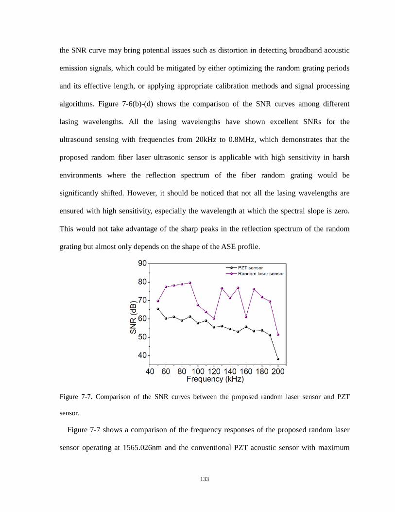
the SNR curve may bring potential issues such as distortion in detecting broadband acoustic
emission signals, which could be mitigated by either optimizing the random grating periods
and its effective length, or applying appropriate calibration methods and signal processing
algorithms. Figure 7-6(b)-(d) shows the comparison of the SNR curves among different
lasing wavelengths. All the lasing wavelengths have shown excellent SNRs for the
ultrasound sensing with frequencies from 20kHz to 0.8MHz, which demonstrates that the
proposed random fiber laser ultrasonic sensor is applicable with high sensitivity in harsh
environments where the reflection spectrum of the fiber random grating would be
significantly shifted. However, it should be noticed that not all the lasing wavelengths are
ensured with high sensitivity, especially the wavelength at which the spectral slope is zero.
This would not take advantage of the sharp peaks in the reflection spectrum of the random
grating but almost only depends on the shape of the ASE profile.
Figure 7-7. Comparison of the SNR curves between the proposed random laser sensor and PZT
sensor.
Figure 7-7 shows a comparison of the frequency responses of the proposed random laser
sensor operating at 1565.026nm and the conventional PZT acoustic sensor with maximum
133

detectable frequency up to 200kHz, where the laser sensor has much better performances.
The sensitivity of the proposed laser sensor could be estimated by:
en = NS
DC
V VS sitivity Vε− (7.4)
where VDC is the DC output voltage. The sensitivities of the proposed random laser sensor
and the PZT sensor are compared at 90kHz where the laser sensor has the maximum
response as shown in Table 7-1. The strain induced by the PZT actuator at 90kHz is
estimated to be around 50nε by using Eq. (7.2) and the proposed random laser sensor has a
better sensitivity than that of the PZT sensor. It should be noted that the laser sensor’s VN
includes the noise of the relaxation oscillation of the random laser, which limits the
sensitivity of the proposed laser sensor. While in the estimation of the SNR of the laser
sensor’s frequency response, the relaxation oscillation noise is not counted, leading to better
SNR performance.
Table 7-1. Sensitivities of the random laser sensor and PZT sensor @ 90kHz VS (V) VN (V) VDC (V) Sensitivity (nε-1)
Laser sensor 3.35 0.05 0.01 6.60
PZT sensor 0.08 0.002 0.001 1.56
7.4 Conclusion
In summary, a highly sensitive random fiber laser based ultrasound sensor is proposed and
demonstrated. The fiber random grating, being the random distributed feedback provider and
sensing element, shows remarkable properties for the random lasing such as the support of
single-mode lasing and excellent sensing performance with high sensitivity over a broad
operating wavelength range. The proposed sensor is able to achieve broadband ultrasound
detection within 0.8MHz with high SNR and is an ideal sensor in harsh environment with
134

large temperature or strain variations. It is believed that the proposed laser sensor is a truly
practical ultrasonic sensor and would find important applications in many ultrasound-related
areas such as structural health monitoring, geophysical exploration, material testing, and
biomedicine.
135

Chapter 8 Time-delay signature
suppression in a chaotic
semiconductor laser by fiber random
grating induced distributed feedback
This chapter presents a novel technique to conceal the time delay signature (TDS) of the
chaotic semiconductor laser output by utilizing random distributed feedback from a fiber
random grating. A theoretical model is developed based on the Lang-Kobayashi model in
order to numerically explore the chaotic dynamics of the laser diode subjected to the random
distributed feedback. It is predicted that the random distributed feedback is superior to the
single reflection feedback in suppressing the TDS. In experiments, a massive number of
feedbacks with randomly varied time delays induced by a fiber random grating introduce
large numbers of external cavity modes into the semiconductor laser, leading to the high
dimension of chaotic dynamics and thus the concealment of the TDS. The obtained TDS with
the maximum suppression is 0.0088, which is the smallest to date. Section 8.1 gives the
background of TDS suppression of chaotic semiconductor lasers. Section 8.2 introduces the
experimental configuration of the chaotic semiconductor laser with fiber random grating
feedback. Section 8.3 shows the theoretical model and simulated results. Section 8.4 presents
the experimental results of TDS suppression by fiber random grating feedback. Section 8.5
draws the final conclusion.
136

8.1 Introduction
Chaos theory reveals that a nonlinear high dimension system may bifurcate to more
complex dynamics including chaos [175]. This erratic behavior has been investigated
intensively in more practical lasers and has remained a fertile research field for the past
decades [28, 29]. Chaotic signals generated from semiconductor lasers are of great interests
for a number of promising applications, including high-speed random bit generation, secure
communication, data encryption, and chaotic ranging [35, 38, 176-185]. Particularly, laser
diode based chaotic output has acted as a physical entropy source for true random number
generation, benefiting from outcome unpredictability with no dependence on any previous
outcome. The most effective and simplest method to perturb the single mode semiconductor
laser into chaos is by returning a small fraction of the laser emission into the laser diode
cavity using an external reflector [31, 186, 187]. Coherence collapse dynamics is expected
when the frequency of the external cavity is much smaller than the laser’s intrinsic relaxation
oscillation frequency, leading to high-dimensional chaotic behavior [33]. However, such
time-delay systems often suffer from feedback time delay signature (TDS), which could be
easily identified by the autocorrelation function (ACF). TDS is potentially detrimental in
chaos-based cryptosystems and truly random number generation [188]. Hence its suppression
is important and highly desired for these applications. To this end, various feedback
configurations, including simple single mirror feedback [189], dual-path feedback from
double mirrors [190], and fiber Bragg grating feedback [191, 192], have been investigated
and studied. More complex configurations including mutually coupled feedback using two
lasers [193, 194], feedback with cascaded coupled laser injection [195], and on-chip
integrated optical feedback [196] have also been proposed to suppress the TDS. However,
137

these techniques increase the hardware complexity of the experimental setup and are not
fully applicable in a practical sense.
In this chapter, a simple approach for TDS suppression is developed by employing the
feedback from a fiber random grating fabricated by the femtosecond (fs) laser with a large
number (>104) of reflectors with random time delays. Randomly placed reflectors along the
fiber provide effective random distributed feedback to a laser diode, which is capable of
obscuring the TDS of the chaotic output. A theoretical model is established to illustrate the
chaotic dynamics of the laser diode subjected to the random distributed feedback and the
simulated results predict the larger suppression ratio than that of the single mirror feedback
configuration. The experimental results obtained from the random grating feedback show the
TDS could be suppressed to a value of 0.0088, which is the smallest value reported to date.
8.2 Experimental configuration
138

Figure 8-1. (a) Configuration of the laser diode subjected to fiber random grating feedback. OC:
Optical Circulator; EDFA: Erbium Doped Fiber Amplifier; PC: Polarization Controller; Atn: Optical
Attenuator; PD: Photo-detector; (b) Reflection spectrum of fiber random grating. Inset: enlarged
reflection spectrum.
The configuration of the laser diode with random grating feedback is shown in Figure 8-
1(a). Light from a single mode laser diode was first amplified with an Erbium-doped fiber
amplifier (EDFA) by passing it through an optical circulator (OC1). A polarization controller
(PC1) was used to adjust the state of polarization (SOP) of the amplified light before it is
reflected by the random grating. The fiber random grating was manufactured using a fs pulse
duration regeneratively amplified Ti:sapphire laser operating at 800nm and having an 80 fs
pulse duration. Index modification spots with random spacing from 0 to 3.5μm were written
along the fiber axis using a precision air bearing stage to translate the fiber and 50×
microscope objective to focus the beam [136]. Around 50000 spots were made along the
10cm long standard single mode fiber (SMF). Figure 8-1(b) shows an example of the
reflection spectrum of the random grating. A strong interference pattern generated by the
backscattered light from different scattering centers is observed (see inset Figure 8-1(b)) and
could be regarded as the result of the superposition of numerous Fabry-Perot interferometers
and Mach-Zehnder interferometers formed by the index modification spots. The random
distributed feedback from the random grating is then passed through a 95/5 coupler. The 5%
of the tapped light was detected by a photo-detector (Newport) with a bandwidth of 25GHz
and its time domain series was recorded by an oscilloscope. The 95% of the tapped light was
sent as the feedback to the laser diode. PC2 was to ensure that the polarizations reflected
back from the random grating were equal with that entering into. An optical attenuator was
used to adjust the strength of the feedback to the laser diode and a power meter was used to
139

measure the feedback strength.
8.3 Theoretical model and simulated results
Figure 8-2. Simplified model of the randomly distributed scattering centers in fiber random grating.
In order to investigate the influence of random distributed optical feedback on the
dynamics of the chaotic semiconductor laser, the fiber random grating could be theoretically
modeled as a collection of large number of enhanced Rayleigh scattering centers randomly
distributed along the SMF with L=10cm. Each scattering center introduces optical feedback
with a specific delay to the laser diode. As shown in Figure 8-2, a simplified model is
developed for the random grating sample. The random grating can be divided into M sections
with equal length L/M. Each section has one scattering center, which is randomly located
within the section with uniform distribution and assumed to have equal reflection
coefficients. The position of each scattering center is denoted as Zm. The optical path length
of the fiber ring structure is 53.5m and the leading fiber length of the random grating sample
is L0=4.01m, corresponding to a total time delay of 307.6ns.
If the light from the laser diode is denoted as E(t)=A(t)eiφ(t), under the random distributed
optical feedback and neglecting multiple reflections among the scattering centers, the laser
field can be numerically simulated by modifying the Lang-Kobayashi model [188, 197-200]
as follows:
140

02
1
02
1
202
( )1 1 1 ( )cos[ ( ) ( )]+ ( )2 1
( )1 1 1 ( )sin[ ( ) ( )]+ ( )2 1
( )1
ϕ
τ ωτ ϕ ϕ ττ τε
ϕ α τ ωτ ϕ ϕ τε τ τ
τ ε
=
=
−= − + − + − −
+ −
= − + − + − − +
−= − −
+
∑
∑
M
m m m m Amp in
M
m m m mmp in
thN
g N NdA A k A t t t F tdt E
g N Nd k A t t t F tdt A A
g N NdN NpJ Adt A
(8.1)
with
( )=2 / 2 ( )
( ) (1/ ) 2 ( )ϕ ϕ
β β ζ
β ζ
+
=A AF t N A N t
F t A N t (8.2)
where km and τm are the feedback reflectivity and feedback delay for each scattering center in
the fiber random grating, respectively. km is equal for all of the M scattering centers and τm
follows uniform distribution within each divided section. Considering the computing
efficiency and the limited computing power of the computers in the lab, simulations with
M=100 and 200 were performed, respectively. Although the M value used in simulation is
smaller than the number of reflectors in the fiber random grating, it is still able to predict the
TDS suppression as shown later in this letter. The parameters of the laser used in simulations
are listed as follows: N0=4.55×10²³ m-3 is the transparency carrier density, g=3×10-12 m3s-1 is
the differential gain, ε=5×10-23 m3 is the gain saturation parameter, τp=1.17ps is the photon
lifetime, τN=2.5ns is the carrier lifetime, α=5.0 is the linewidth enhancement factor,
τin=7.38ps is the round-trip time in the laser diode cavity, Jth=6.568×1032 m-3s-1 is the
threshold current density, p=2.0 is the pumping factor, ω=2πc/λ is the angular frequency of
the laser field, where λ=1550nm and c=3×10⁸ m/s, FA(t) and Fφ(t) are polar decomposition
in amplitude and phase of the spontaneous emission noise, including the fluctuations arising
from the spontaneous process and denoted in the form of the Langevin noise source, β is the
spontaneous emission rate, ζA(t) and ζφ(t) represent uncorrelated white Gaussian noises with
141

zero mean and correlations following <ζA(t)>= <ζφ(t)>=0 and <ζA(t)ζA(t’)>= <ζφ(t)ζφ(t’)>=δ(t-
t’) and <ζA(t)ζφ(t’)>=0, the spontaneous emission noise is about eight orders of magnitude
smaller than the laser field in amplitude.
Numerical simulations were performed using Eq. (8.1) and (8.2) with random distributed
feedback and single reflection feedback, respectively. In simulations, the current density J
was set as 2Jth, at which the intrinsic relaxation oscillation frequency of the laser diode was
around 7GHz. The ACF of the chaotic laser output is computed to obtain the TDS using the
following equation:
2 2 1/2
( ( ) ( ) )( ( ) ( ) )( )
( ( ( ) ( ) ) ( ( ) ( ) ) )
ττ
τ
− + −=
− + −
I t I t I t I tC
I t I t I t I t (8.3)
where I(t) is the chaotic time domain series, τ is the time delay.
Figure 8-3. Simulation results of (a) time domain series, (b) power spectra, and (c) ACFs for laser
diode subjected to single reflection feedback (1) and random distributed feedback (2), respectively.
Figure 8-3(a)-(c) plot the time domain series of the chaotic laser output, power spectra,
and ACFs of the output signals for single reflection feedback and random distributed
142

feedback, respectively. The total feedback reflectivity from the distributed feedback in the
simulation is the same as the single reflection feedback, which is 0.09 in amplitude. With this
level of feedback strength, the laser diode is perturbed into a state of chaotic emission as
shown in column 1 of Figure 8-3. Although the power spectra for both cases look similar, the
ACFs of the time domain series show obvious TDS for the single reflection feedback while
the TDS is significantly suppressed and hardly noticeable for the random distributed
feedback. This indicates that random distributed feedback is able to obscure the periodicity
in the time domain series by introducing many sets of the external cavity modes to the laser
diode, leading to chaotic emission free from the TDS.
Figure 8-4. Computed TDS values of the chaotic laser subjected to single reflection feedback (black)
and random distributed feedbacks from 10cm long random grating with 100 scattering centers (red),
10cm long random grating with 200 scattering centers (blue), 20cm long random grating with 100
scattering centers (dark cyan) as a function of feedback ratio.
The influence of reflection ratios on the TDS for both cases was also investigated as
143
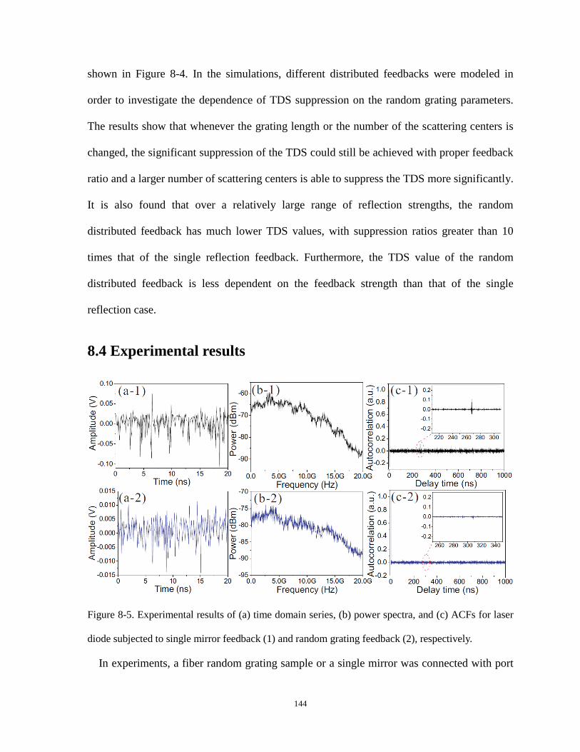
shown in Figure 8-4. In the simulations, different distributed feedbacks were modeled in
order to investigate the dependence of TDS suppression on the random grating parameters.
The results show that whenever the grating length or the number of the scattering centers is
changed, the significant suppression of the TDS could still be achieved with proper feedback
ratio and a larger number of scattering centers is able to suppress the TDS more significantly.
It is also found that over a relatively large range of reflection strengths, the random
distributed feedback has much lower TDS values, with suppression ratios greater than 10
times that of the single reflection feedback. Furthermore, the TDS value of the random
distributed feedback is less dependent on the feedback strength than that of the single
reflection case.
8.4 Experimental results
Figure 8-5. Experimental results of (a) time domain series, (b) power spectra, and (c) ACFs for laser
diode subjected to single mirror feedback (1) and random grating feedback (2), respectively.
In experiments, a fiber random grating sample or a single mirror was connected with port
144

2 of OC 2 in Figure 8-1(a), respectively. The laser diode was operating with a driven current
2 times the threshold value, which emitted light with an output power around 1.0mW and an
intrinsic relaxation oscillation frequency of 7GHz. The feedback from the random grating
and the mirror was adjusted to 0.22 (in amplitude) and the experimental results are shown in
Figure 8-5. The measured time domain series, power spectra and ACFs of the chaotic output
signal are obtained for both random grating feedback and mirror feedback. It is noted that the
power spectra for both cases extend to lower frequency range, which could be explained by
the anti-guidance effects in semiconductor lasers induced by the external feedback. The red-
shift is even more obvious in the experimental results than within the simulation results due
to the stronger feedback injected into the laser diode during the experiments. As expected,
the ACF result for random grating feedback shows a significant suppression in the TDS and
the minimum TDS value is obtained when the feedback strength is 0.22, which is only
0.0088 and almost negligible when compared with that of the mirror feedback result.
Figure 8-6. Mutual information of simulated results for chaotic laser subjected to (a) single reflection
feedback and (b) random distributed feedback with a feedback ratio of 0.09; Mutual information of
experimental results for chaotic laser subjected to (c) single mirror feedback and (d) fiber random
grating feedback with a feedback ratio of 0.22.
145

Mutual information (MI) was also computed for the simulated and experimental chaotic
time domain series to justify the suppression of TDS as shown in Figure 8-6 using the
following equation:
( ), ( )
( ( ), ( ))( ) ( ( ), ( )) log( ( )) ( ( ))τ
ττ ττ+
+= ++∑
I t I t
p I t I tM p I t I tp I t p I t
(8.4)
where p(I(t), I(t+τ)) is the joint probability density, p(I(t)) and p(I(t+τ)) are the marginal
probability densities. It is clearly shown that the random distributed feedback from the fiber
random grating is able to effectively cancel the TDS in the chaotic time domain series for
both simulated and experimental results, which is mainly attributed to two effects: i) as the
TDS in the single reflection scheme originates from the beating between the longitudinal
modes in the single external cavity, the large number of scattering centers in the fiber
random grating introduces large numbers of external cavity modes competing for the limited
optical gain. Chaotic instability with high dimension is then expected and a strong and stable
beating between any two of these longitudinal modes is prevented; ii) the random distributed
feedback from the random grating as indicated in the noise-like interfering reflection
spectrum due to the individual point writing technique with less phase control induces the
frequency-dependent group delay, which corresponds to the group velocity dispersion, on
different frequency components of the optical feedback to the laser diode, leading to the
obscuring of the information of round trip time delay.
146

Figure 8-7. (a) TDS value of the chaotic laser subjected to the random grating feedback with the
optimized input SOP to the fiber random grating sample; (b) Power spectra of the chaotic laser output
with different input SOPs to the fiber random grating sample and the corresponding TDS values.
Due to the randomly distributed index modification spots along the fiber random grating,
the directions for the principal birefringence axes of each scattering center are different from
each other. Thus it is impossible to realize the alignment of the SOP of the light launched
into the random grating with the directions of the local principal birefringence axes at each
scattering center, resulting in different reflection coefficients at each reflector. The
suppression performance of the random distributed feedback therefore depends on the SOP
of the light that was launched into the random grating sample, which could be studied by
adjusting PC 1 and keeping PC 2 fixed. It is found that the SOP of the light launched into the
147

random grating significantly influences the TDS of the chaotic output. By adjusting the SOP
of the input light to an optimized state where a large number of scattering centers have
almost comparable contributions to the reflection, the dependence on the feedback strength
of the TDS for the random grating feedback is obtained as shown in Figure 8-7(a). The
feedback strength was varied through the optical attenuator in Figure 8-1(a) and both PCs
were kept unchanged. The measured curve has a similar trend with the simulated result
shown in Figure 8-4 and shows low TDS values over the measured feedback strength range
as expected. However, when the SOP of the light launched into the random grating was
changed, the feedback strength as well as the TDS experiences large variations as shown in
Figure 8-7(b). This phenomenon is mainly attributed to the polarization dependent scattering
from the scattering centers that are fabricated through the fs laser modification in the random
grating. The resultant random birefringence makes the scattering centers highly polarization
dependent and scatter the input light at different reflection levels according to the
polarization matching conditions. Consequently, two distinct situations are expected: i) it is
possible that there is one or two scattering centers that scatter back dominant light power
over the others when perfectly polarization-matched with that of the input light, which
renders similar results with the single reflection feedback and large TDS values; ii) On the
other hand, it is also possible to find an SOP of the input light which leads to a light
backscattering almost equally shared among a number of scattering centers rather than a
reflection by one or two dominant scattering centers, which effectively takes advantages of
the random distributed feedback from the random grating and obscures the periodicity of the
time series. The first three power spectra in Figure 8-7(b) belonging to the first situation
clearly show a periodicity with a frequency spacing of 3.25MHz, which corresponds to the
total ring length of 61.52m. While the periodicity in the last power spectrum which belongs
148

to the second situation is hardly observed. Naturally, the TDS values in the first situation are
much larger than that in the second situation.
8.5 Conclusion
In conclusion, the suppression of TDS has been theoretically and experimentally realized
in a semiconductor laser subjected to the distributed feedback from a fiber random grating. A
theoretical model is established for numerical simulations, which predicts the robustness of
the random distributed feedback in eliminating the periodicity in laser diode-based optical
chaos. The experimental results show a tremendous suppression in TDS with a minimum
value of 0.0088 to date, allowing the effective and simple approach applicable in the
concealment of the encryption system parameters and hence improving the security in optical
chaos based communications.
149
Chapter 9 Summary and future work
9.1 Summary
This thesis mainly focuses on developing a novel fiber random grating using fs laser
micromachining technique and its applications in random fiber lasers and chaotic
semiconductor lasers. The background of fs laser micromachining technique and the
development of fiber random gratings are also reviewed and discussed. The fabrication
process of the novel fiber random grating is described and its optical properties are analyzed
theoretically and demonstrated experimentally. The randomly varying spaced plane-by-plane
writing technique brings novel physical properties to the fiber random grating, such as
multiple interfering reflection spectrum and induced random birefringence along the sample
fiber. Based on its optical properties, a multi-parameter fiber-optic sensor is realized to
simultaneously measure the temperature, axial strain, and surrounding refractive index by
employing a wavelength-division spectral cross-correlation algorithm. Maximum
sensitivities of 10.32 pm/°C, 1.24 pm/με, and −1520.6 pm/RIU were achieved with small
errors for temperature, axial strain, and surrounding refractive index, respectively. The
developed sensor can be potentially applicable in areas of engineering, biomedical,
biological, and environmental sensing with its robust physical strength and high sensitivities.
We have also developed two novel BRFLs with bi-pumping scheme based on the
intrinsic Rayleigh scattering feedback and fiber random grating feedback. In the first work, a
novel BRFL with a narrow linewidth of ~860 Hz was proposed and demonstrated based on
the bi-directionally pumped SBS in a 10-km-long optical fiber. The physical mechanism of
such a random fiber laser is clarified through a random fiber FP resonator, which is built up
150

through the pump depletion effects of SBS at both ends of the fiber and enables narrow
random lasing emission. The novel laser is successfully applied for linewidth
characterization beyond 860 Hz of light source under test. In the second work, fiber random
grating based resonator replaces the intrinsic Rayleigh scattering based resonator in the bi-
pumped BRFL, which significantly enhances the random feedback and increases the lasing
efficiency. The linewidth of the coherent random lasing spike is measured to be ~45.8 Hz
using the heterodyne technique. The intensity and frequency noises are further suppressed
compared to that of the intrinsic Rayleigh feedback resonator based BRFL.
The fiber random grating is also applied in EDF based random fiber lasers, which
realizes both static and dynamic parameter sensing. The fiber random grating provides
numerous polarization-dependent spectral filters, which are superimposed with each other to
generate multiple lasing lines with high signal-to-noise ratio up to 40dB. This gives an access
for a high-fidelity multiple-static-parameter sensing scheme. By controlling the number of
the lasing lines through the SOP of intra-cavity light, different numbers of sensing
parameters can be measured through monitoring the wavelength shift of the lasing lines.
Temperature and strain are simultaneously measured with maximum errors of 2.3oC and
15.2με. Ultrasound detection is also achieved by the fiber random grating based EDF random
laser. Thanks to the random distributed feedback from the fiber random grating, the single-
mode operation of the random fiber laser ensures linear and pure temporal responses to the
broadband ultrasonic acoustic emission from 20kHz to 0.8MHz. The sensitivity of the
ultrasound detection is enhanced by the large number of steep peak areas over a broad
spectral range, by which, the sensing system, with high probability, has a lasing mode at a
steep region of the reflection spectrum where the sensitivity is the greatest. The proposed
sensor is an ideal alternative in harsh environment with large temperature or strain variations.
151
Compared to the conventional piezoelectric acoustic sensors, the novel sensor enables a
signal-to-noise ratio improvement up to 20dB.
Finally, we demonstrate that the time delay signature of a chaotic semiconductor laser
output could be cancelled out by employing the fiber random grating feedback. A modified
Lang-Kobayashi model is developed to explore the chaotic dynamics of the laser diode
subjected to the random distributed feedback. Both the simulations and experiments
demonstrate the concealment of the time delay signature in the chaotic output thanks to the
large numbers of external cavity modes introduced into the semiconductor laser by the fiber
random grating. The induced high dimension of chaotic dynamics suppresses the time delay
signature to a value of 0.0088, which is the smallest to date.
9.2 Future work
The proposed fiber random grating is a novel compact random fiber medium with
enhanced random distributed feedback, which would pave the way for a lot of important
applications and researches. The work summarized in this thesis only introduces part of the
applications of the fiber random grating and will spark further interests in other reliable
researches and implementations.
Future work on fiber random grating may focus on the optimization of its reflection and
transmission strength and further miniaturization. As the fiber random grating used in
previous works has relatively large transmission loss, only the reflection spectrum could be
employed, which significantly complicates the experimental configuration in the fiber
random grating based BRFL with bi-pump scheme. With optimized fabrication technique,
fiber random gratings could be directly inscribed at both ends of the SBS gain fiber, which
eliminates the needs for optical couplers and increases the ratio of the input power coupled to
152

the gain fiber. Thus the random distributed feedback from fiber random grating could be
fully exploited by the laser system, leading to enhanced lasing efficiency. The size of the
fiber random grating may also be miniaturized by writing index modification spots with
denser spacing. Currently the maximum spacing between neighboring spots is 3.5μm, which
could be further decreased to sub-micron. Consequently, more index modification spots
could be made along a shorter length of optical fiber. The decreased length of fiber random
grating would be beneficial for the improvement of both laser intensity and frequency noises,
as the external disturbances will have less impact on the short random cavities with good
packages and soundproof facilities.
Another future work based on the fiber random grating would be developing multi-
wavelength random fiber lasers as narrow-linewidth multi-wavelength fiber lasers are of
significant interests for fiber-optic sensors, spectroscopy, optical communications, and
microwave generation. Although multi-wavelength random fiber lasers with Raman gain and
EDF gain have drawn intensive attention and turned to be a promising light source with
simple design, they suffer from either broadband linewidth or intense mode competition
induced by the homogeneous gain of the EDF. One way to overcome these drawbacks is to
utilize semiconductor optical amplifier based random fiber laser with fiber random grating
feedback, which on one hand mitigates the mode competition and ensures stable multi-
wavelength lasing thanks to the inhomogeneous gain of SOA, and on the other hand is able
to achieve narrow linewidth with the cavity mode suppression by the random distributed
feedback from the fiber random grating.
Furthermore, fiber random grating based random fiber laser is also able to realize
random number generation without time delay signature. With the gain from SOA and
random distributed feedback from fiber random grating, a random fiber ring laser could be
153
built up. By introducing a long fiber delay into the half-open ring cavity, large numbers of
cavity modes would induce high-dimension laser dynamics. By adjusting the pumping power
of SOA and random feedback strength from fiber random grating, a broadband random fiber
laser could be realized for optical random number generation at high speed and without time
delay signature.
154
Curriculum Vitae
Full name Yanping Xu Education
Ph.D. in Physics (Sep.2013-Aug.2017) Department of Physics University of Ottawa, Ottawa, Canada Supervisors: Prof. Xiaoyi Bao and Prof. Ping Lu M.Sc. (Sep.2011-Aug.2013) Department of Physics University of Ottawa, Ottawa, Canada Supervisors: Prof. Xiaoyi Bao and Prof. Ping Lu B.S. (Sep.2007-Jun.2011) College of Physics Jilin University, Changchun, P. R. China
155

Publications
Journal Paper 1. Yanping Xu, Liang Zhang, Liang Chen, and Xiaoyi Bao, “Single-mode
SOA-based 1kHz-linewidth dual-wavelength random fiber laser,” Opt. Express 25(14), 15828-15837 (2017).
2. Yanping Xu, Liang Zhang, Song Gao, Ping Lu, Stephen Mihailov, and Xiaoyi Bao, “Highly sensitive fiber-random-grating based random laser sensor for ultrasound detection,” Opt. Lett. 42(7), 1353-1356 (2017).
3. Yanping Xu, Ping Lu, Liang Chen, and Xiaoyi Bao, “Recent developments in micro-structured fiber optic sensors,” Fibers. 5(1), 3 (2017). (Invited)
4. Yanping Xu, Mingjiang Zhang, Ping Lu, Stephen Mihailov, and Xiaoyi Bao, "Multi-parameter sensor based on random fiber lasers,” AIP Adv. 6, 095009 (2016).
5. Yanping Xu, Song Gao, Ping Lu, Stephen Mihailov, Liang Chen and Xiaoyi Bao, “Low noise Brillouin random fiber laser with random grating based resonator,” Opt. Lett. 41(14), 3197-3200 (2016).
6. Yanping Xu, Meiqi Ren, Yang Lu, Ping Lu, Ping Lu, Xiaoyi Bao, Lixian Wang, Younes Messaddeq and Sophie LaRochelle, “Multi-parameter sensor based on the SBS in the inverse-parabolic graded-index fiber,” Opt. Lett. 41(6), 1138-1141 (2016).
7. Yanping Xu, Ping Lu, Song Gao, Dao Xiang, Ping Lu, Stephen Mihailov and Xiaoyi Bao, “Optical fiber random grating-based multiparameter sensor,” Opt. Lett. 40(23), 5514-5517 (2015).
8. Yanping Xu, Ping Lu, Jia Song, Ping Lu, Liang Chen, Xiaoyi Bao, and Xiaopeng Dong, “Dispersion effects of high-order-mode fiber on temperature and axial strain discrimination,” Photonic Sensors. 5(3), 224-234 (2015).
9. Yanping Xu, Dao Xiang, Zhonghua Ou, Ping Lu, and Xiaoyi Bao, “Random Fabry–Perot resonator-based sub-kHz Brillouin fiber laser to improve spectral resolution in linewidth measurement,” Opt. Lett. 40(9), 1920-1923 (2015).
10. Yanping Xu, Ping Lu, Zengguang Qin, Jeremie Harris, Farhana Baset, Ping Lu, Vedula Ravi Bhardwaj, and Xiaoyi Bao, “Vibration sensing using a tapered bend-insensitive fiber based Mach-Zehnder interferometer,” Opt. Express 21(3), 3031-3042 (2013).
156

11. Yanping Xu, Mingjiang Zhang, Liang Zhang, Ping Lu, Stephen Mihailov, and Xiaoyi Bao, “Suppression of time-delay signature in chaotic semiconductor laser by fiber random grating induced distributed feedback,” Accepted by Optics Letters.
12. Yanping Xu, and Xiaoyi Bao, “Micro-structured fibers and their applications in fiber-optic sensors and random fiber lasers,” Accepted by Canadian Journal of Physics.
13. Liang Zhang, Yanping Xu, Song Gao, Bhavaye Saxena, Liang Chen, and Xiaoyi Bao, “Multi-wavelength coherent Brillouin random fiber laser with ultra-high optical signal-to-noise ratio,” IEEE J. Sel. Top. Quantum Electron. 24(3), 1-8 (2018).
14. Liang Zhang, Yanping Xu, Song Gao, Bhavaye Saxena, Liang Chen, and Xiaoyi Bao, “Linearly polarized low-noise Brillouin random fiber laser,” Opt. Lett. 42(4), 739-742 (2017).
15. Ping Lu, Yanping Xu, Farhana Baset, Xiaoyi Bao, and Ravi Bhardwaj, “In-line fiber microcantilever vibration sensor,” Appl. Phys. Lett. 103, 211113 (2013).
16. Song Gao, Liang Zhang, Yanping Xu, Liang Chen, Xiaoyi Bao, “High-speed truly physical random bit generation via Brillouin random fiber laser with non-uniform fibers,” IEEE Photon. Technol. Lett. 29(16), 1352-1355 (2017).
17. Song Gao, Liang Zhang, Yanping Xu, Ping Lu, Liang Chen, and Xiaoyi Bao, "Tapered fiber based Brillouin random fiber laser and its application for linewidth measurement," Opt. Express 24 (25), 28353-28360 (2016).
18. Dao Xiang, Ping Lu, Yanping Xu, Liang Chen, Xiaoyi Bao, “Random Brillouin fiber laser for tunable ultra-narrow linewidth microwave generation,” Opt. Lett. 41(20), 4839-4842 (2016).
19. Dao Xiang, Ping Lu, Yanping Xu, Song Gao, Liang Chen, and Xiaoyi Bao, “Truly random bit generation based on a novel random Brillouin fiber laser,” Opt. Lett. 40(22), 5415–5418 (2015).
20. Ping Lu, Jeremie Harris, Yanping Xu, Yang Lu, Liang Chen, and Xiaoyi Bao, “Simultaneous refractive index and temperature measurements using a tapered bend-resistant fiber interferometer,” Opt. Lett. 37(22), 4567–4569 (2012).
21. Liang Zhang, Chen Wang, Zhengying Li, Yanping Xu, Bhavaye Saxena, Song Gao, Liang Chen, and Xiaoyi Bao, "High-efficiency Brillouin random fiber laser using all-polarization maintaining ring cavity," Opt. Express 25, 11306-11314 (2017).
22. Jia Song, Wenhai Li, Ping Lu, Yanping Xu, Liang Chen, Xiaoyi Bao, “Long-Range High Spatial Resolution Distributed Temperature and Strain
157
Sensing Based on Optical Frequency-Domain Reflectometry,” Photonics Journal. 6(3), 6801408 (2014)
23. Jeremie Harris, Ping Lu, Hugo Larocque, Yanping Xu, Liang Chen, and Xiaoyi Bao, “Highly sensitive in-fiber interferometric refractometer with temperature and axial strain compensation,” Opt. Express 21(8), 9996-10009 (2013)
Conference Paper 1. Yanping Xu, Mingjiang Zhang, Ping Lu, Stephen Mihailov, and Xiaoyi Bao,
“Multi-parameter fiber-optic sensors based on fiber random grating,” 2017, OFS25th, Jeju, Korea.
2. Yanping Xu, Liang Zhang, Mingjiang Zhang, Ping Lu, Stephen Mihailov, and Xiaoyi Bao, “Fiber random grating feedback induced chaos in semiconductor laser with highly suppressed time-delay signature,” 2017, Optical Fiber Communication Conference, Los Angeles, California, USA.
3. Yanping Xu, Dao Xiang, Zhonghua Ou, Song Gao, and Xiaoyi Bao, “Novel bi-pumped Brillouin random fiber laser and its applications,” 2015, Schawlow-Townes Symposium: Poster Session, Ottawa, Canada.
4. Yanping Xu, Meiqi Ren, Yang Lu, Ping Lu, Xiaoyi Bao, and Sophie LaRochelle. “Multi-parameter sensing based on the stimulated Brillouin scattering of higher-order acoustic modes in OAM fiber,” 2015, OFS24th, Curitiba, Brazil.
5. Yanping Xu, Ping Lu, Farhana Baset, Vedula Ravi Bhardwaj, Xiaoyi Bao. "Bend-insensitive fiber based vibration sensor," 2014, OFS23rd, Santander, Spain.
6. Yanping Xu, Ping Lu, Jia Song, Liang Chen, and Xiaoyi Bao, Xiaopeng Dong, Ping Lu. "Discrimination of temperature and axial strain using dispersion effects of high-order-mode fibers," Sensors, 2013 IEEE, Baltimore, MD, USA.
7. Liang Zhang, Yanping Xu, Song Gao, Bhavaye Saxena, Liang Chen, and Xiaoyi Bao, "Multi-wavelength Coherent Brillouin Random Fiber Laser with High Optical Signal-to-Noise Ratio," 2017, Conference on Lasers and Electro-Optics, San Jose, California, USA.
8. Jérémie Harris, Ping Lu, Hugo Larocque, Yanping Xu, Liang Chen and Xiaoyi Bao. “Temperature and strain compensation for refractive index measurement using bend-insensitive optical fiber,” Photonic Sensors. 15th Annual Photonics North Conference; 2013 June 3-5; Ottawa, ON, Canada.
158

Bibliography
[1] Du, D., Liu, X., Korn, G., Squier, J.; Mourou, G. Laser‐induced breakdown by impact ionization in SiO2 with pulse widths from 7 ns to 150 fs. Applied physics letters 1994, 64, 3071-3073.
[2] Pronko, P., Dutta, S., Squier, J., Rudd, J., Du, D.; Mourou, G. Machining of sub-micron holes using a femtosecond laser at 800 nm. Optics communications 1995, 114, 106-110.
[3] Joglekar, A.P., Liu, H.-h., Spooner, G., Meyhöfer, E., Mourou, G.; Hunt, A. A study of the deterministic character of optical damage by femtosecond laser pulses and applications to nanomachining. Applied Physics B: Lasers and Optics 2003, 77, 25-30.
[4] Chimmalgi, A., Choi, T., Grigoropoulos, C.; Komvopoulos, K. Femtosecond laser aperturless near-field nanomachining of metals assisted by scanning probe microscopy. Applied Physics Letters 2003, 82, 1146-1148.
[5] Gattass, R.R.; Mazur, E. Femtosecond laser micromachining in transparent materials. Nature photonics 2008, 2, 219-225.
[6] Davis, K.M., Miura, K., Sugimoto, N.; Hirao, K. Writing waveguides in glass with a femtosecond laser. Optics letters 1996, 21, 1729-1731.
[7] Sudrie, L., Franco, M., Prade, B.; Mysyrowicz, A. Study of damage in fused silica induced by ultra-short IR laser pulses. Optics Communications 2001, 191, 333-339.
[8] Mihailov, S.J., Smelser, C.W., Lu, P., Walker, R.B., Grobnic, D., Ding, H., Henderson, G.; Unruh, J. Fiber Bragg gratings made with a phase mask and 800-nm femtosecond radiation. Optics letters 2003, 28, 995-997.
[9] Martinez, A., Dubov, M., Khrushchev, I.; Bennion, I. Direct writing of fibre Bragg gratings by femtosecond laser. Electronics Letters 2004, 40, 1170-1172.
[10] Letokhov, V. Stimulated emission of an ensemble of scattering particles with negative absorption. JETP Letters 1967, 5, 212-215.
[11] Letokhov, V. Generation of light by a scattering medium with negative resonance absorption. Soviet Journal of Experimental and Theoretical Physics 1968, 26, 835-840.
[12] Wiersma, D.S., van Albada, M.P.; Lagendijk, A. Random laser? Nature 1995, 373,
[13] Wu, X., Fang, W., Yamilov, A., Chabanov, A., Asatryan, A., Botten, L.; Cao, H. Random lasing in weakly scattering systems. Physical Review A 2006, 74, 053812.
[14] Ambartsumyan, R., Basov, N., Kryukov, P.; Letokhov, V. Laser with nonresonant
159

feedback. JETP Letters 1966, 3, 167-169.
[15] Ambartsumyan, R., Basov, N., Kryukov, P.; Letokhov, V. A laser with a nonresonant feedback. IEEE Journal of Quantum Electronics 1966, 2, 442-446.
[16] Markushev, V.M., Zolin, V.; Briskina, C.M. Luminescence and stimulated emission of neodymium in sodium lanthanum molybdate powders. Quantum Electronics 1986, 16, 281-283.
[17] Lawandy, N.M., Balachandran, R., Gomes, A.; Sauvain, E. Laser action in strongly scattering media. Nature 1994, 368, 436-438.
[18] Cao, H., Zhao, Y., Ong, H., Ho, S., Dai, J.Y., Wu, J.Y.; Chang, R. Ultraviolet lasing in resonators formed by scattering in semiconductor polycrystalline films. Applied Physics Letters 1998, 73, 3656-3658.
[19] Cao, H., Zhao, Y., Ho, S., Seelig, E., Wang, Q.; Chang, R. Random laser action in semiconductor powder. Physical Review Letters 1999, 82, 2278.
[20] Anglos, D., Stassinopoulos, A., Das, R.N., Zacharakis, G., Psyllaki, M., Jakubiak, R., Vaia, R.A., Giannelis, E.P.; Anastasiadis, S.H. Random laser action in organic–inorganic nanocomposites. JOSA B 2004, 21, 208-213.
[21] Frolov, S., Shkunov, M., Fujii, A., Yoshino, K.; Vardeny, Z.V. Lasing and stimulated emission in/spl pi/-conjugated polymers. IEEE journal of quantum electronics 2000, 36, 2-11.
[22] Dice, G., Mujumdar, S.; Elezzabi, A. Plasmonically enhanced diffusive and subdiffusive metal nanoparticle-dye random laser. Applied Physics Letters 2005, 86, 131105.
[23] Li, B., Williams, G., Rand, S., Hinklin, T.; Laine, R. Continuous-wave ultraviolet laser action in strongly scattering Nd-doped alumina. Optics letters 2002, 27, 394-396.
[24] Feng, Y., Huang, S., Qin, G., Musha, M.; Ueda, K.-i. Random microchip laser. Optics express 2005, 13, 121-126.
[25] Polson, R.C.; Vardeny, Z.V. Random lasing in human tissues. Applied physics letters 2004, 85, 1289-1291.
[26] Turitsyn, S.K., Babin, S.A., Churkin, D.V., Vatnik, I.D., Nikulin, M.; Podivilov, E.V. Random distributed feedback fibre lasers. Physics Reports 2014, 542, 133-193.
[27] Turitsyn, S.K., Babin, S.A., El-Taher, A.E., Harper, P., Churkin, D.V., Kablukov, S.I., Ania-Castañón, J.D., Karalekas, V.; Podivilov, E.V. Random distributed feedback fibre laser. Nature Photonics 2010, 4, 231-235.
[28] Henry, C. Theory of the linewidth of semiconductor lasers. IEEE Journal of Quantum Electronics 1982, 18, 259-264.
160
[29] Ohtsubo, J. Semiconductor lasers: stability, instability and chaos, ed.; Springer: 2012.
[30] Schuster, H.G.; Lüdge, K. Nonlinear laser dynamics: from quantum dots to cryptography, ed.; John Wiley & Sons: 2012.
[31] Mukai, T.; Otsuka, K. New route to optical chaos: Successive-subharmonic-oscil-lation cascade in a semiconductor laser coupled to an external cavity. Physical review letters 1985, 55, 1711.
[32] Morikawa, T., Mitsuhashi, Y., Shimada, J.; Kojima, Y. Return-beam-induced oscillations in self-coupled semiconductor lasers. Electronics Letters 1976, 12, 435-436.
[33] Lenstra, D., Verbeek, B.; Den Boef, A. Coherence collapse in single-mode semiconductor lasers due to optical feedback. IEEE Journal of Quantum Electronics 1985, 21, 674-679.
[34] Colet, P.; Roy, R. Digital communication with synchronized chaotic lasers. Optics letters 1994, 19, 2056-2058.
[35] Uchida, A., Amano, K., Inoue, M., Hirano, K., Naito, S., Someya, H., Oowada, I., Kurashige, T., Shiki, M.; Yoshimori, S. Fast physical random bit generation with chaotic semiconductor lasers. Nature Photonics 2008, 2, 728-732.
[36] Kanter, I., Aviad, Y., Reidler, I., Cohen, E.; Rosenbluh, M. An optical ultrafast random bit generator. Nature Photonics 2010, 4, 58-61.
[37] Akizawa, Y., Yamazaki, T., Uchida, A., Harayama, T., Sunada, S., Arai, K., Yoshimura, K.; Davis, P. Fast Random Number Generation With Bandwidth-Enhanced Chaotic Semiconductor Lasers at 8×50 Gb/s. IEEE Photonics Technology Letters 2012, 24, 1042-1044.
[38] Myneni, K., Barr, T.A., Reed, B.R., Pethel, S.D.; Corron, N.J. High-precision ranging using a chaotic laser pulse train. Applied Physics Letters 2001, 78, 1496-1498.
[39] Lin, F.-Y.; Liu, J.-M. Chaotic radar using nonlinear laser dynamics. IEEE Journal of Quantum Electronics 2004, 40, 815-820.
[40] Murali, K., Sinha, S.; Ditto, W.L. Implementation of NOR gate by a chaotic Chua's circuit. International Journal of Bifurcation and Chaos 2003, 13, 2669-2672.
[41] Sinha, S.; Ditto, W.L. Dynamics based computation. Physical Review Letters 1998, 81, 2156.
[42] Feced, R.; Zervas, M.N. Effects of random phase and amplitude errors in optical fiber Bragg gratings. Journal of lightwave technology 2000, 18, 90-101.
[43] Skaar, J.; Feced, R. Reconstruction of gratings from noisy reflection data. JOSA A 2002, 19, 2229-2237.
161

[44] Rosenthal, A.; Horowitz, M. Reconstruction of a fiber Bragg grating from noisy reflection data. JOSA A 2005, 22, 84-92.
[45] Derevyanko, S. Design of a flat-top fiber Bragg filter via quasi-random modulation of the refractive index. Optics letters 2008, 33, 2404-2406.
[46] Yin, H., Gbadebo, A.; Turitsyna, E.G. Top-hat random fiber Bragg grating. Optics letters 2015, 40, 3592-3594.
[47] Gagné, M.; Kashyap, R. Demonstration of a 3 mW threshold Er-doped random fiber laser based on a unique fiber Bragg grating. Optics express 2009, 17, 19067-19074.
[48] Gagné, M., Bojor, L., Maciejko, R.; Kashyap, R. Novel custom fiber Bragg grating fabrication technique based on push-pull phase shifting interferometry. Optics express 2008, 16, 21550-21557.
[49] Gagné, M., Loranger, S., Lapointe, J.; Kashyap, R. Fabrication of high quality, ultra-long fiber Bragg gratings: up to 2 million periods in phase. Optics express 2014, 22, 387-398.
[50] Gagné, M.; Kashyap, R. Random fiber Bragg grating Raman fiber laser. Optics letters 2014, 39, 2755-2758.
[51] Kamrujjaman Serker, N., Wu, Z.; Li, S. A nonphysics-based approach for vibration-based structural health monitoring under changing environmental conditions. Structural Health Monitoring 2010, 9, 145-158.
[52] Topliss, S.M., James, S.W., Davis, F., Higson, S.P.; Tatam, R.P. Optical fibre long period grating based selective vapour sensing of volatile organic compounds. Sensors and Actuators B: Chemical 2010, 143, 629-634.
[53] Grobnic, D., Mihailov, S.J., Smelser, C.W.; Walker, R.B. Multiparameter sensor based on single high-order fiber Bragg grating made with IR-Femtosecond radiation in single-mode fibers. IEEE Sensors Journal 2008, 8, 1223-1228.
[54] Frazão, O., Ferreira, L., Araújo, F.; Santos, J. Applications of fiber optic grating technology to multi-parameter measurement. Fiber and integrated optics 2005, 24, 227-244.
[55] Yang, R., Yu, Y.-S., Chen, C., Xue, Y., Zhang, X.-L., Guo, J.-C., Wang, C., Zhu, F., Zhang, B.-L.; Chen, Q.-D. S-tapered fiber sensors for highly sensitive measurement of refractive index and axial strain. Journal of Lightwave Technology 2012, 30, 3126-3132.
[56] Rao, Y.-J., Wang, Y.-P., Ran, Z.-L.; Zhu, T. Novel fiber-optic sensors based on long-period fiber gratings written by high-frequency CO 2 laser pulses. Journal of Lightwave Technology 2003, 21, 1320.
[57] Zhao, C.-L., Yang, X., Demokan, M.; Jin, W. Simultaneous temperature and refractive
162

index measurements using a 3 slanted multimode fiber Bragg grating. Journal of lightwave technology 2006, 24, 879.
[58] Lu, P., Men, L., Sooley, K.; Chen, Q. Tapered fiber Mach–Zehnder interferometer for simultaneous measurement of refractive index and temperature. Applied Physics Letters 2009, 94, 131110.
[59] Hu, D.J.J., Lim, J.L., Jiang, M., Wang, Y., Luan, F., Shum, P.P., Wei, H.; Tong, W. Long period grating cascaded to photonic crystal fiber modal interferometer for simultaneous measurement of temperature and refractive index. Optics letters 2012, 37, 2283-2285.
[60] Kim, H.-J., Kwon, O.-J., Lee, S.; Han, Y.-G. Polarization-dependent refractometer for discrimination of temperature and ambient refractive index. Optics letters 2012, 37, 1802-1804.
[61] Lu, P., Harris, J., Xu, Y., Lu, Y., Chen, L.; Bao, X. Simultaneous refractive index and temperature measurements using a tapered bend-resistant fiber interferometer. Optics letters 2012, 37, 4567-4569.
[62] Lee, S.-M., Saini, S.S.; Jeong, M.-Y. Simultaneous measurement of refractive index, temperature, and strain using etched-core fiber Bragg grating sensors. IEEE Photonics Technology Letters 2010, 22, 1431-1433.
[63] Alberto, N.J., Marques, C.A., Pinto, J.L.; Nogueira, R.N. Three-parameter optical fiber sensor based on a tilted fiber Bragg grating. Applied Optics 2010, 49, 6085-6091.
[64] Men, L., Lu, P.; Chen, Q. Intelligent multiparameter sensing with fiber Bragg gratings. Applied Physics Letters 2008, 93, 071110.
[65] Trono, C., Baldini, F., Brenci, M., Chiavaioli, F.; Mugnaini, M. Flow cell for strain-and temperature-compensated refractive index measurements by means of cascaded optical fibre long period and Bragg gratings. Measurement Science and Technology 2011, 22, 075204.
[66] Harris, J., Lu, P., Larocque, H., Xu, Y., Chen, L.; Bao, X. Highly sensitive in-fiber interferometric refractometer with temperature and axial strain compensation. Optics express 2013, 21, 9996-10009.
[67] Jin, W., Michie, W.C., Thursby, G., Konstantaki, M.; Culshaw, B. Simultaneous measurement of strain and temperature: error analysis. Optical Engineering 1997, 36, 598-609.
[68] de Matos, C.J., Menezes, L.d.S., Brito-Silva, A.M., Gámez, M.M., Gomes, A.S.; de Araújo, C.B. Random fiber laser. Physical review letters 2007, 99, 153903.
[69] Gysel, P.; Staubli, R.K. Statistical properties of Rayleigh backscattering in single-mode fibers. Journal of Lightwave Technology 1990, 8, 561-567.
163

[70] Van Deventer, M.O. Polarization properties of Rayleigh backscattering in single-mode fibers. Journal of Lightwave Technology 1993, 11, 1895-1899.
[71] Fotiadi, A.A.; Kiyan, R.V. Cooperative stimulated Brillouin and Rayleigh backscattering process in optical fiber. Optics letters 1998, 23, 1805-1807.
[72] Zhu, T., Bao, X.; Chen, L. A single longitudinal-mode tunable fiber ring laser based on stimulated Rayleigh scattering in a nonuniform optical fiber. Journal of Lightwave Technology 2011, 29, 1802-1807.
[73] Li, M.-J., Li, S.; Nolan, D.A. Nonlinear fibers for signal processing using optical Kerr effects. Journal of lightwave technology 2005, 23, 3606.
[74] Lizárraga, N., Puente, N., Chaikina, E., Leskova, T.; Méndez, E. Single-mode Er-doped fiber random laser with distributed Bragg grating feedback. Optics express 2009, 17, 395-404.
[75] Li, Y., Lu, P., Bao, X.; Ou, Z. Random spaced index modulation for a narrow linewidth tunable fiber laser with low intensity noise. Optics letters 2014, 39, 2294-2297.
[76] Zhu, T., Chen, F., Huang, S.; Bao, X. An ultra-narrow linewidth fiber laser based on Rayleigh backscattering in a tapered optical fiber. Laser Physics Letters 2013, 10, 055110.
[77] Agrawal, G.P. Nonlinear fiber optics, ed.; Academic press: 2007.
[78] Rao, Y., Zhang, W., Zhu, J., Yang, Z., Wang, Z.; Jia, X. Hybrid lasing in an ultra-long ring fiber laser. Optics express 2012, 20, 22563-22568.
[79] Churkin, D., Vatnik, I., Turitsyn, S.; Babin, S. Random distributed feedback Raman fiber laser operating in a 1.2 μm wavelength range. Laser Physics 2011, 21, 1525-1529.
[80] Teng, R., Ding, Y.; Chen, L. Random fiber laser operating at 1,115 nm. Applied Physics B 2013, 111, 169-172.
[81] El-Taher, A.E., Harper, P., Babin, S., Churkin, D., Podivilov, E., Ania-Castanon, J.D.; Turitsyn, S. Effect of Rayleigh-scattering distributed feedback on multiwavelength Raman fiber laser generation. Optics letters 2011, 36, 130-132.
[82] Sugavanam, S., Yan, Z., Kamynin, V., Kurkov, A., Zhang, L.; Churkin, D. Multiwavelength generation in a random distributed feedback fiber laser using an all fiber Lyot filter. Optics express 2014, 22, 2839-2844.
[83] Pinto, A.M., Frazão, O., Santos, J.; Lopez-Amo, M. Multiwavelength fiber laser based on a photonic crystal fiber loop mirror with cooperative Rayleigh scattering. Applied Physics B: Lasers and Optics 2010, 99, 391-395.
[84] Pinto, A., Frazão, O., Santos, J.; Lopez-Amo, M. Multiwavelength Raman fiber lasers
164

using Hi-Bi photonic crystal fiber loop mirrors combined with random cavities. Journal of Lightwave Technology 2011, 29, 1482-1488.
[85] Tkach, R.W., Chraplyvy, A.R.; Derosier, R. Spontaneous Brillouin scattering for single-mode optical-fibre characterisation. Electronics Letters 1986, 22, 1011-1013.
[86] Pang, M., Xie, S., Bao, X., Zhou, D.-P., Lu, Y.; Chen, L. Rayleigh scattering-assisted narrow linewidth Brillouin lasing in cascaded fiber. Optics letters 2012, 37, 3129-3131.
[87] Pang, M., Bao, X.; Chen, L. Observation of narrow linewidth spikes in the coherent Brillouin random fiber laser. Optics letters 2013, 38, 1866-1868.
[88] Pang, M., Bao, X., Chen, L., Qin, Z., Lu, Y.; Lu, P. Frequency stabilized coherent Brillouin random fiber laser: theory and experiments. Optics express 2013, 21, 27155-27168.
[89] Giles, C.R.; Desurvire, E. Modeling erbium-doped fiber amplifiers. Journal of lightwave technology 1991, 9, 271-283.
[90] Saxena, B., Bao, X.; Chen, L. Suppression of thermal frequency noise in erbium-doped fiber random lasers. Optics letters 2014, 39, 1038-1041.
[91] Okoshi, T., Kikuchi, K.; Nakayama, A. Novel method for high resolution measurement of laser output spectrum. Electronics letters 1980, 16, 630-631.
[92] Iiyama, K., Hayashi, K.-i., Ida, Y., Ikeda, H.; Sakai, Y. Reflection-type delayed self-homodyne/heterodyne method for optical linewidth measurements. Journal of lightwave technology 1991, 9, 635-640.
[93] Dawson, J.W., Park, N.; Vahala, K.J. An improved delayed self-heterodyne interferometer for linewidth measurements. IEEE Photonics Technology Letters 1992, 4, 1063-1066.
[94] Güttner, A., Welling, H., Gericke, K.; Seifert, W. Fine structure of the field autocorrelation function of a laser in the threshold region. Physical Review A 1978, 18, 1157.
[95] Gallion, P.; Debarge, G. Quantum phase noise and field correlation in single frequency semiconductor laser systems. IEEE Journal of Quantum Electronics 1984, 20, 343-349.
[96] Rowe, H.E. Signals and noise in communication systems. 1965,
[97] Cranch, G.; Miller, G. Fundamental frequency noise properties of extended cavity erbium fiber lasers. Optics letters 2011, 36, 906-908.
[98] Xu, D., Yang, F., Chen, D., Wei, F., Cai, H., Fang, Z.; Qu, R. Laser phase and frequency noise measurement by Michelson interferometer composed of a 3×3 optical fiber coupler. Optics express 2015, 23, 22386-22393.
165

[99] Takushima, Y., Choi, H.; Chung, Y.C. Measurement of Differential Phasor Diagram of Multilevel DPSK Signals by Using an Adjustment-Free Delay Interferometer Composed of a 3×3 Optical Coupler. Journal of Lightwave Technology 2009, 27, 718-730.
[100] Welch, P. The use of fast Fourier transform for the estimation of power spectra: a method based on time averaging over short, modified periodograms. IEEE Transactions on audio and electroacoustics 1967, 15, 70-73.
[101] Jia, X.-H., Rao, Y.-J., Peng, F., Wang, Z.-N., Zhang, W.-L., Wu, H.-J.; Jiang, Y. Random-lasing-based distributed fiber-optic amplification. Optics express 2013, 21, 6572-6577.
[102] Wang, Z., Rao, Y., Wu, H., Li, P., Jiang, Y., Jia, X.; Zhang, W. Long-distance fiber-optic point-sensing systems based on random fiber lasers. Optics express 2012, 20, 17695-17700.
[103] Fernandez-Vallejo, M., Bravo, M.; Lopez-Amo, M. Ultra-long laser systems for remote fiber Bragg gratings arrays interrogation. IEEE Photonics Technology Letters 2013, 25, 1362-1364.
[104] Jia, X.-H., Rao, Y.-J., Wang, Z.-N., Zhang, W.-L., Jiang, Y., Zhu, J.-M.; Yang, Z.-X. Towards fully distributed amplification and high-performance long-range distributed sensing based on random fiber laser. OFS2012 22nd International Conference on Optical Fiber Sensor,
[105] Wang, Z., Zeng, J., Li, J., Fan, M., Wu, H., Peng, F., Zhang, L., Zhou, Y.; Rao, Y. Ultra-long phase-sensitive OTDR with hybrid distributed amplification. Optics letters 2014, 39, 5866-5869.
[106] Li, Y., Lu, P., Baset, F., Ou, Z., Song, J., Alshehri, A., Bhardwaj, V.R.; Bao, X. Narrow linewidth low frequency noise Er-doped fiber ring laser based on femtosecond laser induced random feedback. Applied Physics Letters 2014, 105, 101105.
[107] Gouedard, C., Husson, D., Sauteret, C., Auzel, F.; Migus, A. Generation of spatially incoherent short pulses in laser-pumped neodymium stoichiometric crystals and powders. JOSA B 1993, 10, 2358-2363.
[108] Sha, W., Liu, C.-H.; Alfano, R. Spectral and temporal measurements of laser action of Rhodamine 640 dye in strongly scattering media. Optics letters 1994, 19, 1922-1924.
[109] Wiersma, D.S.; Lagendijk, A. Light diffusion with gain and random lasers. Physical Review E 1996, 54, 4256.
[110] Gottardo, S., Cavalieri, S., Yaroshchuk, O.; Wiersma, D.S. Quasi-two-dimensional diffusive random laser action. Physical review letters 2004, 93, 263901.
[111] Wiersma, D.S. The physics and applications of random lasers. Nature physics 2008, 4,
166

359-367.
[112] Williams, G., Bayram, S., Rand, S., Hinklin, T.; Laine, R. Laser action in strongly scattering rare-earth-metal-doped dielectric nanophosphors. Physical Review A 2001, 65, 013807.
[113] Meng, X., Fujita, K., Zong, Y., Murai, S.; Tanaka, K. Random lasers with coherent feedback from highly transparent polymer films embedded with silver nanoparticles. Applied Physics Letters 2008, 92, 201112.
[114] Ip, E., Lau, A.P.T., Barros, D.J.; Kahn, J.M. Coherent detection in optical fiber systems. Optics express 2008, 16, 753-791.
[115] Subías, J., Heras, C., Pelayo, J.; Villuendas, F. All in fiber optical frequency metrology by selective Brillouin amplification of single peak in an optical comb. Optics express 2009, 17, 6753-6758.
[116] Guyomarc’h, D., Hagel, G., Zumsteg, C.; Knoop, M. Some aspects of simulation and realization of an optical reference cavity. Physical Review A 2009, 80, 063802.
[117] Campos, J.M., Destrez, A., Jacquet, J.; Toffano, Z. Ultra-fast optical spectrum analyzer for DWDM applications. IEEE Transactions on Instrumentation and Measurement 2004, 53, 124-129.
[118] Takakura, T., Iga, K.; Tako, T. Linewidth measurement of a single longitudinal mode AlGaAs laser with a Fabry-Perot interferometer. Japanese Journal of Applied Physics 1980, 19, L725.
[119] Ludvigsen, H., Tossavainen, M.; Kaivola, M. Laser linewidth measurements using self-homodyne detection with short delay. Optics Communications 1998, 155, 180-186.
[120] Horak, P.; Loh, W.H. On the delayed self-heterodyne interferometric technique for determining the linewidth of fiber lasers. Optics express 2006, 14, 3923-3928.
[121] Han, M.; Wang, A. Analysis of a loss-compensated recirculating delayed self-heterodyne interferometer for laser linewidth measurement. Applied Physics B: Lasers and Optics 2005, 81, 53-58.
[122] Chen, X., Han, M., Zhu, Y., Dong, B.; Wang, A. Implementation of a loss-compensated recirculating delayed self-heterodyne interferometer for ultranarrow laser linewidth measurement. Applied optics 2006, 45, 7712-7717.
[123] Domingo, J.S., Pelayo, J., Villuendas, F., Heras, C.; Pellejer, E. Very high resolution optical spectrometry by stimulated Brillouin scattering. IEEE Photonics Technology Letters 2005, 17, 855-857.
[124] Sevillano, P., Subías, J., Heras, C., Pelayo, J.; Villuendas, F. Brillouin induced self-heterodyne technique for narrow line width measurement. Optics express 2010, 18,
167

15201-15206.
[125] Mihélic, F., Bacquet, D., Zemmouri, J.; Szriftgiser, P. Ultrahigh resolution spectral analysis based on a Brillouin fiber laser. Optics letters 2010, 35, 432-434.
[126] Bao, X.; Chen, L. Recent progress in Brillouin scattering based fiber sensors. Sensors 2011, 11, 4152-4187.
[127] Churkin, D.V., Sugavanam, S., Vatnik, I.D., Wang, Z., Podivilov, E.V., Babin, S.A., Rao, Y.; Turitsyn, S.K. Recent advances in fundamentals and applications of random fiber lasers. Advances in Optics and Photonics 2015, 7, 516-569.
[128] Fotiadi, A.A. Random lasers: An incoherent fibre laser. Nature Photonics 2010, 4, 204-205.
[129] Sugavanam, S., Tarasov, N., Shu, X.; Churkin, D.V. Narrow-band generation in random distributed feedback fiber laser. Optics express 2013, 21, 16466-16472.
[130] El-Taher, A., Alcon-Camas, M., Babin, S., Harper, P., Ania-Castanón, J.D.; Turitsyn, S.K. Dual-wavelength, ultralong Raman laser with Rayleigh-scattering feedback. Optics letters 2010, 35, 1100-1102.
[131] Babin, S., El-Taher, A., Harper, P., Podivilov, E.; Turitsyn, S. Tunable random fiber laser. Physical Review A 2011, 84, 021805.
[132] Churkin, D.V., El-Taher, A.E., Vatnik, I.D., Ania-Castañón, J.D., Harper, P., Podivilov, E.V., Babin, S.A.; Turitsyn, S.K. Experimental and theoretical study of longitudinal power distribution in a random DFB fiber laser. Optics express 2012, 20, 11178-11188.
[133] Smirnov, S.V.; Churkin, D.V. Modeling of spectral and statistical properties of a random distributed feedback fiber laser. Optics express 2013, 21, 21236-21241.
[134] Xu, Y., Xiang, D., Ou, Z., Lu, P.; Bao, X. Random Fabry–Perot resonator-based sub-kHz Brillouin fiber laser to improve spectral resolution in linewidth measurement. Optics letters 2015, 40, 1920-1923.
[135] Xiang, D., Lu, P., Xu, Y., Gao, S., Chen, L.; Bao, X. Truly random bit generation based on a novel random Brillouin fiber laser. Optics letters 2015, 40, 5415-5418.
[136] Xu, Y., Lu, P., Gao, S., Xiang, D., Mihailov, S.; Bao, X. Optical fiber random grating-based multiparameter sensor. Optics letters 2015, 40, 5514-5517.
[137] Gaeta, A.L.; Boyd, R.W. Stimulated Brillouin scattering in the presence of external feedback. International Journal of Nonlinear Optical Physics 1992, 1, 581-594.
[138] Chiu, B.; Hastings, M.C. Digital demodulation for passive homodyne optical fiber interferometry based on a 3 x 3 coupler. SPIE's 1994 International Symposium on Optics, Imaging, and Instrumentation,
168

[139] Foster, S., Tikhomirov, A.; Milnes, M. Fundamental thermal noise in distributed feedback fiber lasers. IEEE journal of quantum electronics 2007, 43, 378-384.
[140] Foster, S., Cranch, G.A.; Tikhomirov, A. Experimental evidence for the thermal origin of 1/f frequency noise in erbium-doped fiber lasers. Physical Review A 2009, 79, 053802.
[141] Zhu, J.-L., Li, W.-H., Sun, Y., Lu, J.-G., Song, X.-L., Chen, C.-Y., Zhang, Z.; Su, Y. Random laser emission in a sphere-phase liquid crystal. Applied Physics Letters 2015, 106, 191903.
[142] Sakai, M., Inose, Y., Ema, K., Ohtsuki, T., Sekiguchi, H., Kikuchi, A.; Kishino, K. Random laser action in GaN nanocolumns. Applied Physics Letters 2010, 97, 151109.
[143] Yu, S., Yuen, C., Lau, S., Park, W.I.; Yi, G.-C. Random laser action in ZnO nanorod arrays embedded in ZnO epilayers. Applied physics letters 2004, 84, 3241-3243.
[144] Dubois, J.; La Rochelle, S., Active cooperative tuned identification friend or foe (ACTIFF). 1999, Google Patents.
[145] Wiersma, D.S.; Cavalieri, S. Light emission: A temperature-tunable random laser. Nature 2001, 414, 708-709.
[146] Redding, B., Choma, M.A.; Cao, H. Speckle-free laser imaging using random laser illumination. Nature photonics 2012, 6, 355-359.
[147] Choe, R., Corlu, A., Lee, K., Durduran, T., Konecky, S.D., Grosicka‐Koptyra, M., Arridge, S.R., Czerniecki, B.J., Fraker, D.L.; DeMichele, A. Diffuse optical tomography of breast cancer during neoadjuvant chemotherapy: a case study with comparison to MRI. Medical physics 2005, 32, 1128-1139.
[148] Vatnik, I.D., Churkin, D.V.; Babin, S.A. Power optimization of random distributed feedback fiber lasers. Optics express 2012, 20, 28033-28038.
[149] Hu, Z., Miao, B., Wang, T., Fu, Q., Zhang, D., Ming, H.; Zhang, Q. Disordered microstructure polymer optical fiber for stabilized coherent random fiber laser. Optics letters 2013, 38, 4644-4647.
[150] Martins, H., Marques, M.B.; Frazão, O. 300 km-ultralong Raman fiber lasers using a distributed mirror for sensing applications. Optics express 2011, 19, 18149-18154.
[151] Jia, X.-H., Rao, Y.-J., Wang, Z.-N., Zhang, W.-L., Yuan, C.-X., Yan, X.-D., Li, J., Wu, H., Zhu, Y.-Y.; Peng, F. Distributed Raman amplification using ultra-long fiber laser with a ring cavity: characteristics and sensing application. Optics express 2013, 21, 21208-21217.
[152] Dorighi, J.F., Krishnaswamy, S.; Achenbach, J.D. Stabilization of an embedded fiber optic Fabry-Perot sensor for ultrasound detection. IEEE transactions on ultrasonics,
169

ferroelectrics, and frequency control 1995, 42, 820-824.
[153] Dewhurst, R.J.; Shan, Q. Optical remote measurement of ultrasound. Measurement Science and Technology 1999, 10, R139.
[154] Betz, D.C., Thursby, G., Culshaw, B.; Staszewski, W.J. Acousto-ultrasonic sensing using fiber Bragg gratings. Smart Materials and Structures 2003, 12, 122.
[155] Xu, M.; Wang, L.V. Photoacoustic imaging in biomedicine. Review of scientific instruments 2006, 77, 041101.
[156] Wild, G.; Hinckley, S. Acousto-ultrasonic optical fiber sensors: overview and state-of-the-art. IEEE Sensors Journal 2008, 8, 1184-1193.
[157] Grosse, C.U.; Ohtsu, M. Acoustic emission testing, ed.; Springer Science & Business Media: 2008.
[158] Fomitchov, P.; Krishnaswamy, S. Response of a fiber Bragg grating ultrasonic sensor. Optical Engineering 2003, 42, 956-963.
[159] Qiao, Y., Zhou, Y.; Krishnaswamy, S. Adaptive demodulation of dynamic signals from fiber Bragg gratings using two-wave mixing technology. Applied optics 2006, 45, 5132-5142.
[160] Tsuda, H., Kumakura, K.; Ogihara, S. Ultrasonic sensitivity of strain-insensitive fiber Bragg grating sensors and evaluation of ultrasound-induced strain. Sensors 2010, 10, 11248-11258.
[161] Liu, T., Hu, L.; Han, M. Multiplexed fiber-ring laser sensors for ultrasonic detection. Optics express 2013, 21, 30474-30480.
[162] Guan, B.-O., Jin, L., Zhang, Y.; Tam, H.-Y. Polarimetric heterodyning fiber grating laser sensors. Journal of lightwave technology 2012, 30, 1097-1112.
[163] Perez, I.M., Cui, H.; Udd, E. Acoustic emission detection using fiber Bragg gratings. SPIE's 8th Annual International Symposium on Smart Structures and Materials,
[164] Okabe, Y., Fujibayashi, K., Shimazaki, M., Soejima, H.; Ogisu, T. Delamination detection in composite laminates using dispersion change based on mode conversion of Lamb waves. Smart materials and structures 2010, 19, 115013.
[165] Wu, Q.; Okabe, Y. Ultrasonic sensor employing two cascaded phase-shifted fiber Bragg gratings suitable for multiplexing. Optics letters 2012, 37, 3336-3338.
[166] Wu, Q.; Okabe, Y. High-sensitivity ultrasonic phase-shifted fiber Bragg grating balanced sensing system. Optics express 2012, 20, 28353-28362.
[167] Rosenthal, A., Razansky, D.; Ntziachristos, V. High-sensitivity compact ultrasonic detector based on a pi-phase-shifted fiber Bragg grating. Optics letters 2011, 36, 1833-
170

1835.
[168] Rosenthal, A., Kellnberger, S., Bozhko, D., Chekkoury, A., Omar, M., Razansky, D.; Ntziachristos, V. Sensitive interferometric detection of ultrasound for minimally invasive clinical imaging applications. Laser & Photonics Reviews 2014, 8, 450-457.
[169] Tsuda, H. Fiber Bragg grating vibration-sensing system, insensitive to Bragg wavelength and employing fiber ring laser. Optics letters 2010, 35, 2349-2351.
[170] Han, M., Liu, T., Hu, L.; Zhang, Q. Intensity-demodulated fiber-ring laser sensor system for acoustic emission detection. Optics express 2013, 21, 29269-29276.
[171] Wu, Q., Okabe, Y.; Sun, J. Investigation of dynamic properties of erbium fiber laser for ultrasonic sensing. Optics express 2014, 22, 8405-8419.
[172] Xu, Y., Zhang, M., Lu, P., Mihailov, S.; Bao, X. Multi-parameter sensor based on random fiber lasers. AIP Advances 2016, 6, 095009.
[173] Minardo, A., Cusano, A., Bernini, R., Zeni, L.; Giordano, M. Response of fiber Bragg gratings to longitudinal ultrasonic waves. IEEE transactions on ultrasonics, ferroelectrics, and frequency control 2005, 52, 304-312.
[174] Liu, T.; Han, M. Analysis of π-Phase-Shifted Fiber Bragg Gratings for Ultrasonic Detection. IEEE Sensors Journal 2012, 12, 2368-2373.
[175] Feigenbaum, M.J. The onset spectrum of turbulence. Physics Letters A 1979, 74, 375-378.
[176] Sciamanna, M.; Shore, K.A. Physics and applications of laser diode chaos. Nature Photonics 2015, 9, 151-162.
[177] Wu, W.-T., Liao, Y.-H.; Lin, F.-Y. Noise suppressions in synchronized chaos lidars. Optics express 2010, 18, 26155-26162.
[178] Argyris, A., Syvridis, D., Larger, L., Annovazzi-Lodi, V., Colet, P., Fischer, I., Garcia-Ojalvo, J., Mirasso, C.R., Pesquera, L.; Shore, K.A. Chaos-based communications at high bit rates using commercial fibre-optic links. Nature 2005, 438, 343-346.
[179] Lin, F.-Y.; Liu, J.-M. Diverse waveform generation using semiconductor lasers for radar and microwave applications. IEEE journal of quantum electronics 2004, 40, 682-689.
[180] Annovazzi-Lodi, V., Aromataris, G., Benedetti, M.; Merlo, S. Secure chaotic transmission on a free-space optics data link. IEEE Journal of Quantum Electronics 2008, 44, 1089-1095.
[181] Lin, F.-Y.; Liu, J.-M. Chaotic lidar. IEEE journal of selected topics in quantum electronics 2004, 10, 991-997.
171

[182] Uchida, A., Davis, P.; Itaya, S. Generation of information theoretic secure keys using a chaotic semiconductor laser. Applied physics letters 2003, 83, 3213-3215.
[183] Takeuchi, Y., Shogenji, R.; Ohtsubo, J. Chaotic dynamics in semiconductor lasers subjected to polarization-rotated optical feedback. Applied Physics Letters 2008, 93, 181105.
[184] Wang, A., Li, P., Zhang, J., Zhang, J., Li, L.; Wang, Y. 4.5 Gbps high-speed real-time physical random bit generator. Optics express 2013, 21, 20452-20462.
[185] Wang, A., Wang, L., Li, P.; Wang, Y. Minimal-post-processing 320-Gbps true random bit generation using physical white chaos. Optics Express 2017, 25, 3153-3164.
[186] Mørk, J., Mark, J.; Tromborg, B. Route to chaos and competition between relaxation oscillations for a semiconductor laser with optical feedback. Physical review letters 1990, 65, 1999.
[187] Erneux, T., Gavrielides, A.; Sciamanna, M. Stable microwave oscillations due to external-cavity-mode beating in laser diodes subject to optical feedback. Physical Review A 2002, 66, 033809.
[188] Rontani, D., Locquet, A., Sciamanna, M., Citrin, D.S.; Ortin, S. Time-delay identification in a chaotic semiconductor laser with optical feedback: a dynamical point of view. IEEE Journal of Quantum Electronics 2009, 45, 879-1891.
[189] Rontani, D., Locquet, A., Sciamanna, M.; Citrin, D. Loss of time-delay signature in the chaotic output of a semiconductor laser with optical feedback. Optics letters 2007, 32, 2960-2962.
[190] Wu, J.-G., Xia, G.-Q.; Wu, Z.-M. Suppression of time delay signatures of chaotic output in a semiconductor laser with double optical feedback. Optics express 2009, 17, 20124-20133.
[191] Li, S.-S.; Chan, S.-C. Chaotic time-delay signature suppression in a semiconductor laser with frequency-detuned grating feedback. IEEE Journal of Selected Topics in Quantum Electronics 2015, 21, 541-552.
[192] Li, S.-S., Liu, Q.; Chan, S.-C. Distributed feedbacks for time-delay signature suppression of chaos generated from a semiconductor laser. IEEE Photonics Journal 2012, 4, 1930-1935.
[193] Hong, Y. Experimental study of time-delay signature of chaos in mutually coupled vertical-cavity surface-emitting lasers subject to polarization optical injection. Optics express 2013, 21, 17894-17903.
[194] Wu, J.-G., Wu, Z.-M., Tang, X., Lin, X.-D., Deng, T., Xia, G.-Q.; Feng, G.-Y. Simultaneous generation of two sets of time delay signature eliminated chaotic signals by using mutually coupled semiconductor lasers. IEEE Photonics Technology Letters
172

2011, 23, 759-761.
[195] Li, N., Pan, W., Xiang, S., Yan, L., Luo, B.; Zou, X. Loss of time delay signature in broadband cascade-coupled semiconductor lasers. IEEE Photonics Technology Letters 2012, 24, 2187-2190.
[196] Sunada, S., Harayama, T., Arai, K., Yoshimura, K., Davis, P., Tsuzuki, K.; Uchida, A. Chaos laser chips with delayed optical feedback using a passive ring waveguide. Optics express 2011, 19, 5713-5724.
[197] Uchida, A., Heil, T., Liu, Y., Davis, P.; Aida, T. High-frequency broad-band signal generation using a semiconductor laser with a chaotic optical injection. IEEE journal of quantum electronics 2003, 39, 1462-1467.
[198] Lang, R.; Kobayashi, K. External optical feedback effects on semiconductor injection laser properties. IEEE journal of Quantum Electronics 1980, 16, 347-355.
[199] Wang, A., Yang, Y., Wang, B., Zhang, B., Li, L.; Wang, Y. Generation of wideband chaos with suppressed time-delay signature by delayed self-interference. Optics express 2013, 21, 8701-8710.
[200] Agrawal, G.P.; Dutta, N.K. Semiconductor lasers, ed.; Springer Science & Business Media: 2013.
173


