
www.Fisher.com
Fisher� 3582 and 3582i Positioners, 582iElectro-Pneumatic Converter, and 3583 ValveStem Position TransmittersContents
Introduction 2. . . . . . . . . . . . . . . . . . . . . . . . . . . . . . . Scope of Manual 2. . . . . . . . . . . . . . . . . . . . . . . . . . Description 2. . . . . . . . . . . . . . . . . . . . . . . . . . . . . .
Type Number Descriptions 6. . . . . . . . . . . . . . . . Specifications 6. . . . . . . . . . . . . . . . . . . . . . . . . . . . Educational Services 6. . . . . . . . . . . . . . . . . . . . . .
Installation 6. . . . . . . . . . . . . . . . . . . . . . . . . . . . . . . . Special Instructions for “Safe Use” and
Installation in Hazardous Areas forfor 582i Converter 7. . . . . . . . . . . . . . . . . . . . .
CSA 8. . . . . . . . . . . . . . . . . . . . . . . . . . . . . . . . . . . FM 8. . . . . . . . . . . . . . . . . . . . . . . . . . . . . . . . . . . . ATEX 8. . . . . . . . . . . . . . . . . . . . . . . . . . . . . . . . . . IECEx 9. . . . . . . . . . . . . . . . . . . . . . . . . . . . . . . . . . NEPSI 10. . . . . . . . . . . . . . . . . . . . . . . . . . . . . . . . INMETRO 10. . . . . . . . . . . . . . . . . . . . . . . . . . . . .
Mounting 11. . . . . . . . . . . . . . . . . . . . . . . . . . . . . . . Changing Cam Position 14. . . . . . . . . . . . . . . . . . . Pressure Connections 15. . . . . . . . . . . . . . . . . . . .
Supply Connection 15. . . . . . . . . . . . . . . . . . . . . . Output Connection 15. . . . . . . . . . . . . . . . . . . . . . Instrument Connection 15. . . . . . . . . . . . . . . . . . Diagnostic Connections 16. . . . . . . . . . . . . . . . .
Vent 17. . . . . . . . . . . . . . . . . . . . . . . . . . . . . . . . . . . Electrical Connections for 3582i
Valve Positioner 18. . . . . . . . . . . . . . . . . . . . . . . 582i Converter Installation 19. . . . . . . . . . . . . . . .
Operating Information 20. . . . . . . . . . . . . . . . . . . . . Valve Positioner Cam Information 20. . . . . . . . . . Valve Stem Position Transmitter Cam
Information 21. . . . . . . . . . . . . . . . . . . . . . . . . . .
(continued on page 2)
CONTROL VALVE WITH3582i POSITIONER
CONTROL VALVE WITH3583 TRANSMITTER
CONTROL VALVE WITH3582 POSITIONER
W5498-1 W8424W5499-1
Figure 1. Typical Mounting for Fisher 3582 and 3582i Positioners and 3583 Transmitters
Instruction ManualD200138X012December 2009 3582, 582i, and 3583

3582, 582i, and 3583Instruction Manual
December 2009
2
Contents (cont’d)Valve Positioner Bypass Operation 21. . . . . . . . . Input Signal Ranges 22. . . . . . . . . . . . . . . . . . . . . . Valve Positioner Split-Range Operation 22. . . . . Changing Valve Positioner Action 23. . . . . . . . . . Changing Valve Stem Position Transmitter
Action 23. . . . . . . . . . . . . . . . . . . . . . . . . . . . . . . . Calibration Of Valve Positioner Or
Valve Stem Position Transmitter 24. . . . . . . . . . Beam Alignment 24. . . . . . . . . . . . . . . . . . . . . . . . . Calibration 25. . . . . . . . . . . . . . . . . . . . . . . . . . . . . .
Principle of Operation 26. . . . . . . . . . . . . . . . . . . . . . 3582 Valve Positioners 26. . . . . . . . . . . . . . . . . . . 3582i Valve Positioner 27. . . . . . . . . . . . . . . . . . . . 3583 Valve Stem Position Transmitters 27. . . . .
Maintenance 28. . . . . . . . . . . . . . . . . . . . . . . . . . . . . Changing the Range Spring 29. . . . . . . . . . . . . . . Replacing Gaskets 29. . . . . . . . . . . . . . . . . . . . . . . Replacing the Nozzle O-Ring 30. . . . . . . . . . . . . . Replacing the Relay 30. . . . . . . . . . . . . . . . . . . . . . Adjusting the Flapper Pivot 30. . . . . . . . . . . . . . . . Replacing the 582i Converter
Primary O-Ring and Filter 31. . . . . . . . . . . . . . . Replacing the 582i Converter Housing
Cap O-Ring 31. . . . . . . . . . . . . . . . . . . . . . . . . . . Removing the 582i Converter 31. . . . . . . . . . . . . . Reassembling the 582i Converter 31. . . . . . . . . .
Parts Ordering 32. . . . . . . . . . . . . . . . . . . . . . . . . . . . Parts Kits 32. . . . . . . . . . . . . . . . . . . . . . . . . . . . . . . . Parts List 33. . . . . . . . . . . . . . . . . . . . . . . . . . . . . . . . Loop Schematics/Nameplates 46. . . . . . . . . . . . . .
Introduction
Scope of ManualThis instruction manual includes installation,operation, calibration, maintenance, and partsordering information for Fisher 3582 pneumatic valvepositioners, the 3582i electro-pneumatic valvepositioner, and 3583 pneumatic valve stem positiontransmitters. Refer to separate instruction manualsfor information on the control valve, actuator, andaccessories.
Do not install, operate or maintain a 3582 pneumaticvalve positioner, a 3582i electro-pneumatic valvepositioner, or a 3583 pneumatic valve stem positiontransmitter without being fully trained and qualified invalve, actuator and accessory installation, operationand maintenance. To avoid personal injury orproperty damage it is important to carefully read,understand, and follow all of the contents of thismanual, including all safety cautions and warnings. If
you have any questions about these instructions,contact your Emerson Process Management salesoffice before proceeding.
Description3582 pneumatic valve positioners and the 3582ielectro-pneumatic valve positioner shown in figure 1are used with diaphragm-actuated, sliding-stemcontrol valve assemblies. The pneumatic valvepositioners receive a pneumatic input signal from acontrol device and modulate the supply pressure tothe control valve actuator. The positioner adjusts theactuator supply pressure to maintain a valve stemposition proportional to the pneumatic input signal.
3582NS positioners are designed for nuclear powerapplications. The 3582NS construction includesmaterials that provide superior performance atelevated temperature and radiation levels. TheO-rings are EPDM (ethylene propylene) and thediaphragms are EPDM/meta-aramid fabric. EPDMdemonstrates superior temperature capability andshelf life over nitrile. The meta-aramid diaphragmfabric demonstrates improved strength retention atelevated temperature and radiation conditions.
CAUTION
Use a clean, dry, oil-free air supplywith instruments containing EPDMcomponents. EPDM is subject todegradation when exposed topetroleum-based lubricants.
Under the 10CFR50, Appendix B, quality assuranceprogram, the 3582NS positioner is qualifiedcommercial grade dedicated. These can be suppliedas 10CFR, Part 21 items.
The 3582i is an electro-pneumatic valve positioner,consisting of a 582i electro-pneumatic converterinstalled on a 3582 pneumatic valve positioner. The3582i valve positioner provides an accurate valvestem position that is proportional to a DC currentinput signal.
The 582i electro-pneumatic converter is a modularunit that can be installed at the factory or in the field.However, do not install a 582i converter on anexisting positioner until you contact your EmersonProcess Management sales office for applicationassistance.

3582, 582i, and 3583Instruction Manual
December 2009
3
Table 1. Specifications for Fisher 3582 and 3582i Valve Positioners
Input Signal
3582:� 0.2 to 1.0 bar (3 to 15 psig), � 0.4 to 2.0 bar(6 to 30 psig), or � split range, see table 123582i:4 to 20 mA DC constant current with 30 VDCmaximum compliance voltage, can be split range,see table 12
Equivalent Circuit for 3582i
The 582i converter equivalent circuit is 120 ohms,shunted by three 5.6-volt zener diodes (see figure 10)
Output Signal
Type: Pneumatic pressure as required byactuator up to 95 percent of maximum supplyAction: Field-reversible between � direct and� reverse within the pneumatic valve positioner
Supply Pressure(1)
Recommended: 0.3 bar (5 psi) above actuatorrequirementMaximum: 3.4 bar (50 psig) or pressure rating ofactuator, whichever is lower
Supply Medium: air or natural gas(2)
Note: The 3582i is not approved for use withnatural gas as the supply medium
Input Bellows Pressure Rating(1)
See table 11 for minimum and maximum pressureratings (allowable input signal) for each availablerange spring
Maximum Steady-State Air Consumption(3)
For 35821.4 bar (20 psig) Supply: 0.38 normal m3/hr(14.0 scfh)2.0 bar (30 psig) Supply: 0.48 normal m3/hr(18.0 scfh)2.4 bar (35 psig) Supply: 0.54 normal m3/hr(20.0 scfh)For 3582i Only1.4 bar (20 psig) Supply: 0.46 normal m3/hr(17.2 scfh)2.0 bar (30 psig) Supply: 0.57 normal m3/hr(21.4 scfh)2.4 bar (35 psig) Supply: 0.64 normal m3/hr(23.8 scfh)
Maximum Supply Air Demand
For 3582 and 3582i1.4 bar (20 psig) Supply: 4.4 normal m3/hr (164.5 scfh)2.0 bar (30 psig) Supply: 6.7 normal m3/hr (248.5 scfh)2.4 bar (35 psig) Supply: 7.7 normal m3/hr (285.5 scfh)
Performance
3582Independent Linearity: ±1 percent of output signalspanHysteresis: 0.5 percent of span
For 3582i OnlyIndependent Linearity: ±2 percent of output signalspanHysteresis: 0.6 percent of span
Electromagnetic Compatibility for 582ielectro-pneumatic converterMeets EN 61326-1 (First Edition)
Immunity—Industrial locations per Table 2 ofthe EN 61326-1 standard. Performance isshown in table 3 below.
Emissions—Class AISM equipment rating: Group 1, Class A
Note: The electromagnetic compatibilityspecifications also apply to the 3582i
For 3582 and 3582iTypical Open Loop Gain (Output Signal):� 100 in the range of 0.2 to 1.0 bar (3 to 15 psig)� 55 in the range of 0.4 to 2.0 bar (6 to 30 psig)
Operating Influences
Supply Pressure, For 3582 Units: Valve travelchanges less than 1.67 percent per bar (0.25percent per 2 psi) change in supply pressureSupply Pressure, For 3582i Units: Valve travelchanges less than 3.62 percent per bar (1.5percent per 2 psi) change in supply pressure
Operative Temperature Limits(1)
Standard Construction, For 3582 and 3582iUnits: −40 to +71�C (−40 to +160�F)3582NS Units: −40 to +82�C (−40 to +180�F)with EPDM elastomersHigh-Temperature Construction, For 3582Aand C only: −18 to +104�C (0 to +220�F) withoutgauges
- continued -
3582, 582i, and 3583Instruction Manual
December 2009
4
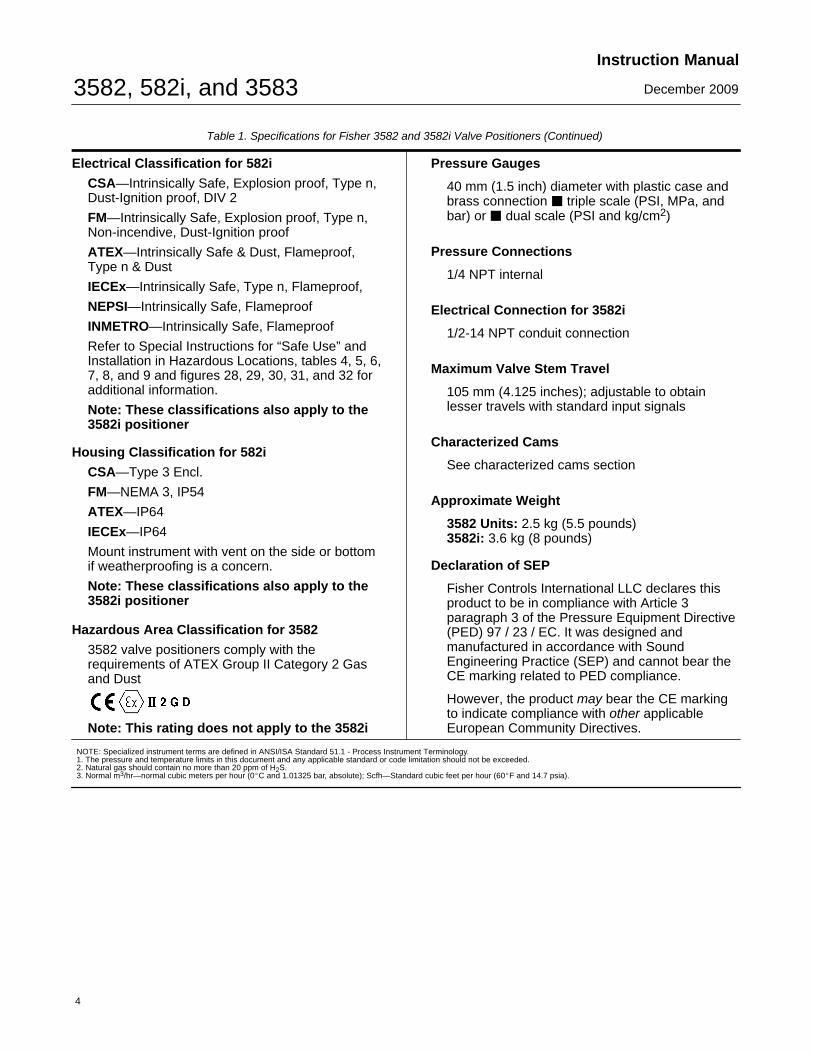
Table 1. Specifications for Fisher 3582 and 3582i Valve Positioners (Continued)
Electrical Classification for 582i
CSA—Intrinsically Safe, Explosion proof, Type n,Dust-Ignition proof, DIV 2
FM—Intrinsically Safe, Explosion proof, Type n,Non-incendive, Dust-Ignition proof
ATEX—Intrinsically Safe & Dust, Flameproof, Type n & Dust
IECEx—Intrinsically Safe, Type n, Flameproof,
NEPSI—Intrinsically Safe, Flameproof
INMETRO—Intrinsically Safe, Flameproof
Refer to Special Instructions for “Safe Use” andInstallation in Hazardous Locations, tables 4, 5, 6,7, 8, and 9 and figures 28, 29, 30, 31, and 32 foradditional information.
Note: These classifications also apply to the3582i positioner
Housing Classification for 582i
CSA—Type 3 Encl.
FM—NEMA 3, IP54
ATEX—IP64
IECEx—IP64
Mount instrument with vent on the side or bottomif weatherproofing is a concern.
Note: These classifications also apply to the3582i positioner
Hazardous Area Classification for 3582
3582 valve positioners comply with therequirements of ATEX Group II Category 2 Gasand Dust
Note: This rating does not apply to the 3582i
Pressure Gauges
40 mm (1.5 inch) diameter with plastic case andbrass connection � triple scale (PSI, MPa, andbar) or � dual scale (PSI and kg/cm2)
Pressure Connections
1/4 NPT internal
Electrical Connection for 3582i
1/2-14 NPT conduit connection
Maximum Valve Stem Travel
105 mm (4.125 inches); adjustable to obtainlesser travels with standard input signals
Characterized Cams
See characterized cams section
Approximate Weight
3582 Units: 2.5 kg (5.5 pounds)3582i: 3.6 kg (8 pounds)
Declaration of SEP
Fisher Controls International LLC declares thisproduct to be in compliance with Article 3paragraph 3 of the Pressure Equipment Directive(PED) 97 / 23 / EC. It was designed andmanufactured in accordance with SoundEngineering Practice (SEP) and cannot bear theCE marking related to PED compliance.
However, the product may bear the CE markingto indicate compliance with other applicableEuropean Community Directives.
NOTE: Specialized instrument terms are defined in ANSI/ISA Standard 51.1 - Process Instrument Terminology.1. The pressure and temperature limits in this document and any applicable standard or code limitation should not be exceeded.2. Natural gas should contain no more than 20 ppm of H2S.3. Normal m3/hr—normal cubic meters per hour (0�C and 1.01325 bar, absolute); Scfh—Standard cubic feet per hour (60�F and 14.7 psia).
3582, 582i, and 3583Instruction Manual
December 2009
5
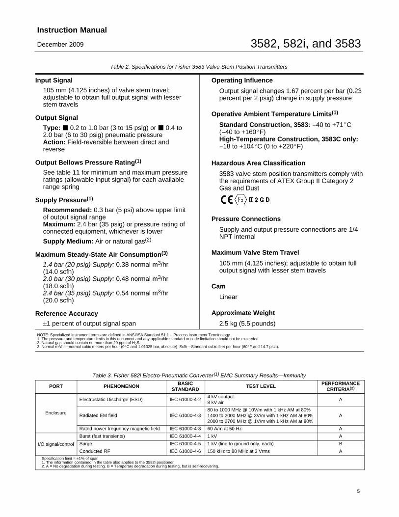
Table 2. Specifications for Fisher 3583 Valve Stem Position Transmitters
Input Signal
105 mm (4.125 inches) of valve stem travel;adjustable to obtain full output signal with lesserstem travels
Output Signal
Type: � 0.2 to 1.0 bar (3 to 15 psig) or � 0.4 to2.0 bar (6 to 30 psig) pneumatic pressureAction: Field-reversible between direct andreverse
Output Bellows Pressure Rating(1)
See table 11 for minimum and maximum pressureratings (allowable input signal) for each availablerange spring
Supply Pressure(1)
Recommended: 0.3 bar (5 psi) above upper limitof output signal rangeMaximum: 2.4 bar (35 psig) or pressure rating ofconnected equipment, whichever is lower
Supply Medium: Air or natural gas(2)
Maximum Steady-State Air Consumption(3)
1.4 bar (20 psig) Supply: 0.38 normal m3/hr(14.0 scfh)2.0 bar (30 psig) Supply: 0.48 normal m3/hr(18.0 scfh)2.4 bar (35 psig) Supply: 0.54 normal m3/hr(20.0 scfh)
Reference Accuracy
±1 percent of output signal span
Operating Influence
Output signal changes 1.67 percent per bar (0.23percent per 2 psig) change in supply pressure
Operative Ambient Temperature Limits(1)
Standard Construction, 3583: −40 to +71�C(−40 to +160�F)High-Temperature Construction, 3583C only:−18 to +104�C (0 to +220�F)
Hazardous Area Classification
3583 valve stem position transmitters comply withthe requirements of ATEX Group II Category 2Gas and Dust
Pressure Connections
Supply and output pressure connections are 1/4NPT internal
Maximum Valve Stem Travel
105 mm (4.125 inches); adjustable to obtain fulloutput signal with lesser stem travels
Cam
Linear
Approximate Weight
2.5 kg (5.5 pounds)
NOTE: Specialized instrument terms are defined in ANSI/ISA Standard 51.1 − Process Instrument Terminology.1. The pressure and temperature limits in this document and any applicable standard or code limitation should not be exceeded.2. Natural gas should contain no more than 20 ppm of H2S.3. Normal m3/hr—normal cubic meters per hour (0�C and 1.01325 bar, absolute); Scfh—Standard cubic feet per hour (60�F and 14.7 psia).
Table 3. Fisher 582i Electro-Pneumatic Converter(1) EMC Summary Results—Immunity
PORT PHENOMENON BASICSTANDARD
TEST LEVEL PERFORMANCECRITERIA(2)
Enclosure
Electrostatic Discharge (ESD) IEC 61000-4-24 kV contact8 kV air
A
Radiated EM field IEC 61000-4-380 to 1000 MHz @ 10V/m with 1 kHz AM at 80%1400 to 2000 MHz @ 3V/m with 1 kHz AM at 80%2000 to 2700 MHz @ 1V/m with 1 kHz AM at 80%
A
Rated power frequency magnetic field IEC 61000-4-8 60 A/m at 50 Hz A
I/O signal/control
Burst (fast transients) IEC 61000-4-4 1 kV A
Surge IEC 61000-4-5 1 kV (line to ground only, each) B
Conducted RF IEC 61000-4-6 150 kHz to 80 MHz at 3 Vrms A
Specification limit = ±1% of span1. The information contained in the table also applies to the 3582i positioner.2. A = No degradation during testing. B = Temporary degradation during testing, but is self-recovering.

3582, 582i, and 3583Instruction Manual
December 2009
6
The 582i converter receives the DC current inputsignal and, through a nozzle/flapper arrangement,provides a proportional pneumatic output signal.This pneumatic output signal provides the inputsignal to the pneumatic valve positioner, eliminatingthe need for a remote-mounted transducer.
3583 pneumatic valve stem position transmitters arefor use with sliding-stem diaphragm actuators.These units provide an output signal that is directlyproportional to the valve stem position.
Refer to the type number description for a detailedexplanation of type numbers.
Type Number Descriptions
The following descriptions provide specificinformation on the different valve positioner or valvestem position transmitter constructions. If the typenumber is not known, refer to the nameplate on thepositioner. For the location of the nameplate, refer tokey 25 in figure 20.
3582—Pneumatic valve positioner with bypass andinstrument, supply, and output pressure gauges.
3582A—Pneumatic valve positioner without bypassand without pressure gauges.
3582C—Pneumatic valve positioner without bypassand with automotive tire valves instead of pressuregauges.
3582D—Pneumatic valve positioner with bypass andwith automotive tire valves instead of pressuregauges.
3582G—Pneumatic valve positioner without bypassand with instrument, supply, and output pressuregauges.
3582NS—Pneumatic valve positioner for nuclearservice applications with or without bypass and withautomotive tire valves instead of pressure gauges.
3582i—Electro-pneumatic valve positioner withoutbypass; with 582i converter; and with: supply andoutput pressure gauges, automotive tire valves, orpipe plugs.
582i—Electro-pneumatic converter with: supply andoutput pressure gauges, automotive tire valves, orpipe plugs. Used for conversion of a 4-20 mA inputsignal to a 0.2 to 1.0 bar (3 to 15 psig) input signalfor the pneumatic valve positioner.
3583—Pneumatic valve stem position transmitterwith supply and output pressure gauges.
3583C—Similar to the 3583 valve stem positiontransmitter except with automotive tire valves inplace of pressure gauges.
SpecificationsSpecifications for the valve positioners are shown intable 1. Specifications for the valve stem positiontransmitters are shown in table 2.
Refer to the unit nameplate to determine the type ofpositioner or transmitter, supply pressure, etc.
WARNING
This product is intended for a specificcurrent range, temperature range andother application specifications.Applying different current, temperatureand other service conditions couldresult in malfunction of the product,property damage or personal injury.
Educational ServicesFor information on available courses for 3852, 3582iand 3583, as well as a variety of other products,contact:
Emerson Process ManagementEducational Services, RegistrationP.O. Box 190; 301 S. 1st Ave.Marshalltown, IA 50158-2823Phone: 800−338−8158 orPhone: 641−754−3771Fax: 641−754−3431e-mail: [email protected]
InstallationIf using natural gas as the pneumatic supplymedium, natural gas will be used in the pressureconnections of the unit to any connected equipment.The unit will vent natural gas into the surroundingatmosphere, unless it is remote vented.
WARNING
Always wear protective clothing,gloves, and eyewear when performing
3582, 582i, and 3583Instruction Manual
December 2009
7
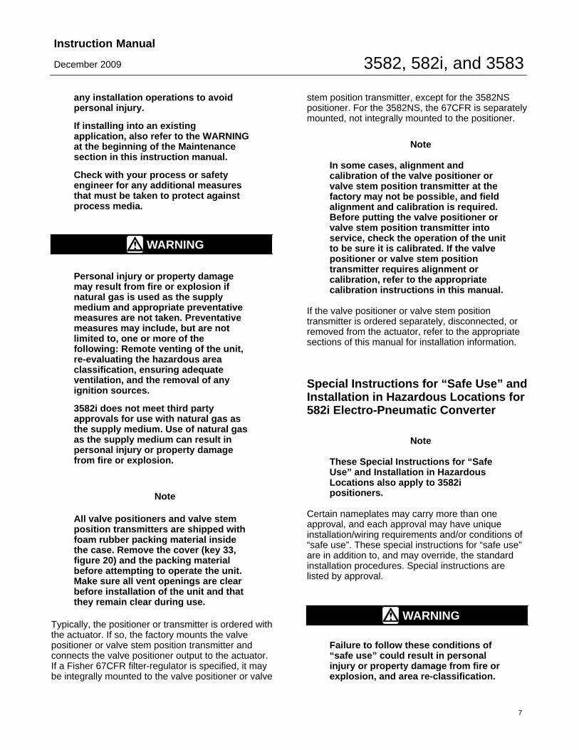
any installation operations to avoidpersonal injury.
If installing into an existingapplication, also refer to the WARNINGat the beginning of the Maintenancesection in this instruction manual.
Check with your process or safetyengineer for any additional measuresthat must be taken to protect againstprocess media.
WARNING
Personal injury or property damagemay result from fire or explosion ifnatural gas is used as the supplymedium and appropriate preventativemeasures are not taken. Preventativemeasures may include, but are notlimited to, one or more of thefollowing: Remote venting of the unit,re-evaluating the hazardous areaclassification, ensuring adequateventilation, and the removal of anyignition sources.
3582i does not meet third partyapprovals for use with natural gas asthe supply medium. Use of natural gasas the supply medium can result inpersonal injury or property damagefrom fire or explosion.
Note
All valve positioners and valve stemposition transmitters are shipped withfoam rubber packing material insidethe case. Remove the cover (key 33,figure 20) and the packing materialbefore attempting to operate the unit.Make sure all vent openings are clearbefore installation of the unit and thatthey remain clear during use.
Typically, the positioner or transmitter is ordered withthe actuator. If so, the factory mounts the valvepositioner or valve stem position transmitter andconnects the valve positioner output to the actuator.If a Fisher 67CFR filter-regulator is specified, it maybe integrally mounted to the valve positioner or valve
stem position transmitter, except for the 3582NSpositioner. For the 3582NS, the 67CFR is separatelymounted, not integrally mounted to the positioner.
Note
In some cases, alignment andcalibration of the valve positioner orvalve stem position transmitter at thefactory may not be possible, and fieldalignment and calibration is required.Before putting the valve positioner orvalve stem position transmitter intoservice, check the operation of the unitto be sure it is calibrated. If the valvepositioner or valve stem positiontransmitter requires alignment orcalibration, refer to the appropriatecalibration instructions in this manual.
If the valve positioner or valve stem positiontransmitter is ordered separately, disconnected, orremoved from the actuator, refer to the appropriatesections of this manual for installation information.
Special Instructions for “Safe Use” andInstallation in Hazardous Locations for582i Electro-Pneumatic Converter
Note
These Special Instructions for “SafeUse” and Installation in HazardousLocations also apply to 3582ipositioners.
Certain nameplates may carry more than oneapproval, and each approval may have uniqueinstallation/wiring requirements and/or conditions of“safe use”. These special instructions for “safe use”are in addition to, and may override, the standardinstallation procedures. Special instructions arelisted by approval.
WARNING
Failure to follow these conditions of“safe use” could result in personalinjury or property damage from fire orexplosion, and area re-classification.

3582, 582i, and 3583Instruction Manual
December 2009
8
Table 4. Hazardous Area Classifications for Fisher 582i Converter(1)—CSA (Canada)CERTIFICATION
BODYCERTIFICATION OBTAINED ENTITY RATING TEMPERATURE CODE ENCLOSURE RATING
CSA
Ex ia Intrinsically SafeEx ia IIC T4/T5/T6 per drawing GE28591Class I, II Division 1 GP A,B,C,D,E,F,GT4/T5/T6 per drawing GE28591
Vmax = 30 VDCImax = 150 mAPi = 1.25 WCi = 0 nFLi = 0 mH
T4 (Tamb � 71°C)T5 (Tamb � 62°C)T6 (Tamb � 47°C)
CSA Type 3 Encl.
Explosion ProofEx d IIC T6Class I, Division I, GP A,B,C,D T6
− − − T6 (Tamb � 71°C) CSA Type 3 Encl.
Type nEx nA IIC T6
− − − T6 (Tamb � 71°C) CSA Type 3 Encl.
Class I, Division 2, GP A,B,C,D T6Class II, Division 1 GP E,F,G T6Class II Division 2 GP F,G T6
− − − T6 (Tamb � 71°C) CSA Type 3 Encl.
1.These hazardous area classification also apply to 3582i positioners.
Table 5. Hazardous Area Classifications for Fisher 582i Converter(1)—FM (United States)CERTIFICATION
BODYCERTIFICATION OBTAINED ENTITY RATING TEMPERATURE CODE ENCLOSURE RATING
FM
Intrinsically SafeClass I Zone 0 AEx ia IIC T4/T5/T6 per drawing GE28590Class I, II, III Division 1 GP A,B,C,D,E,F,GT4/T5/T6 per drawing GE28590
Vmax = 30 VDCImax = 150 mAPi = 1.25 WCi = 0 nFLi = 0 mH
T4 (Tamb � 71°C)T5 (Tamb � 62°C)T6 (Tamb � 47°C)
NEMA 3, IP54
Explosion ProofClass I Zone 1 AEx d IIC T6Class I, Division I, GP A,B,C,D T6
− − − T6 (Tamb � 71°C) NEMA 3, IP54
Type nClass I Zone 2 AEx nA IIC T6
− − − T6 (Tamb � 71°C) NEMA 3, IP54
Class I Division 2, GP A,B,C,D T6Class II Division 1, GP E,F,G T6Class II Division 2, GP F,G T6
− − − T6 (Tamb � 71°C) NEMA 3, IP54
1.These hazardous area classification also apply to 3582i positioners.
CSA
Special Conditions of Use
Intrinsically Safe, Explosion proof, Type n,Dust-Ignition proof, DIV 2
No conditions of safe use.
Refer to table 4 for additional information, figure 28for CSA loop schematics, and figure 29 for theCSA/FM approvals nameplate.
FM
Special Conditions of Use
Intrinsically Safe, Explosion proof, Type n,Non-incendive, Dust-Ignition proof
No conditions of safe use.
Refer to table 4 for additional information, figure 30for the FM loop schematic, and figure 29 for theCSA/FM approvals nameplate.
ATEX
Special Conditions for Safe Use
Intrinsically Safe, Dust
This equipment is intrinsically safe and can be usedin potentially explosive atmospheres.
The electrical parameters of certified equipmentwhich can be connected to the device must notexceed one of these following values:
Uo � 30 Vdc ; Io � 150 mA ; Po � 1.25 W
3582, 582i, and 3583Instruction Manual
December 2009
9
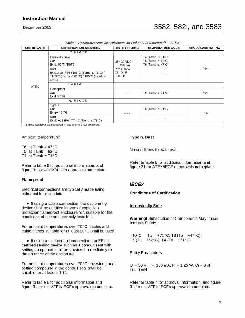
Table 6. Hazardous Area Classifications for Fisher 582i Converter(1)—ATEXCERTIFICATE CERTIFICATION OBTAINED ENTITY RATING TEMPERATURE CODE ENCLOSURE RATING
ATEX
II 1 G & D
Intrisically SafeGasEx ia IIC T4/T5/T6
Ui = 30 VDCIi = 150 mAPi = 1.25 WCi = 0 nFLi = 0 mH
T4 (Tamb � 71°C)T5 (Tamb � 62°C)T6 (Tamb � 47°C)
IP64DustEx iaD 20 IP64 T109°C (Tamb � 71°C) /T100°C (Tamb � 62°C) / T85°C (Tamb �47°C)
− − −
II 2 G & D
FlameproofGasEx d IIC T6
− − − T6 (Tamb � 71°C) IP64
II 3 G & D
Type nGasEx nA IIC T6 − − −
T6 (Tamb � 71°C)IP64
DustEx tD A21 IP64 T74°C (Tamb � 71°C)
− − −
1.These hazardous area classification also apply to 3582i positioners.
Ambient temperature:
T6, at Tamb = 47�CT5, at Tamb = 62�CT4, at Tamb = 71�C
Refer to table 6 for additional information, and figure 31 for ATEX/IECEx approvals nameplate.
Flameproof
Electrical connections are typically made usingeither cable or conduit.
� If using a cable connection, the cable entrydevice shall be certified in type of explosionprotection flameproof enclosure “d”, suitable for theconditions of use and correctly installed.
For ambient temperatures over 70�C, cables andcable glands suitable for at least 90�C shall be used.
� If using a rigid conduit connection, an EEx dcertified sealing device such as a conduit seat withsetting compound shall be provided immediately tothe entrance of the enclosure.
For ambient temperatures over 70�C, the wiring andsetting compound in the conduit seal shall besuitable for at least 90�C.
Refer to table 6 for additional information and figure 31 for the ATEX/IECEx approvals nameplate.
Type n, Dust
No conditions for safe use.
Refer to table 6 for additional information and figure 31 for ATEX/IECEx approvals nameplate.
IECEx
Conditions of Certification
Intrinsically Safe
Warning! Substitution of Components May ImpairIntrinsic Safety
−40�C Ta +71�C; T6 (Ta +47�C);T5 (Ta +62�C); T4 (Ta +71�C)
Entity Parameters
Ui = 30 V, li = 150 mA, Pi = 1.25 W, Ci = 0 nF, Li = 0 mH
Refer to table 7 for approval information, and figure31 for the ATEX/IECEx approvals nameplate.
3582, 582i, and 3583Instruction Manual
December 2009
10
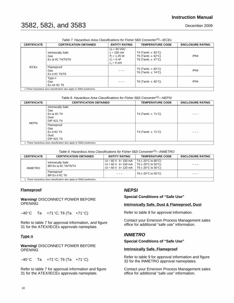
Table 7. Hazardous Area Classifications for Fisher 582i Converter(1)—IECExCERTIFICATE CERTIFICATION OBTAINED ENTITY RATING TEMPERATURE CODE ENCLOSURE RATING
IECEx
Intrinsically SafeGasEx ia IIC T4/T5/T6
Ui = 30 VDCIi = 150 mAPi = 1.25 WCi = 0 nFLi = 0 mH
T4 (Tamb � 82°C)T5 (Tamb � 62°C)T6 (Tamb � 47°C)
IP64
FlameproofGasEx d IIC T5/T6
− − −T5 (Tamb � 82°C)T6 (Tamb � 74°C)
IP64
Type nGasEx nA IIC T6
− − − T6 (Tamb � 82°C) IP64
1.These hazardous area classification also apply to 3582i positioners.
Table 8. Hazardous Area Classifications for Fisher 582i Converter(1)—NEPSICERTIFICATE CERTIFICATION OBTAINED TEMPERATURE CODE ENCLOSURE RATING
NEPSI
Intrinsically SafeGasEx ia IIC T4DustDIP A21 T4
T4 (Tamb � 71°C) − − −
FlameproofGasEx d IIC T4DustDIP A21 T4
T4 (Tamb � 71°C) − − −
1. These hazardous area classification also apply to 3582i positioners.
Table 9. Hazardous Area Classifications for Fisher 582i Converter(1)—INMETROCERTIFICATE CERTIFICATION OBTAINED ENTITY RATING TEMPERATURE CODE ENCLOSURE RATING
INMETRO
Intrinsically SafeBR-Ex ia IIC T6/T5/T4
Ui = 60 V Ii= 150 mAUi = 60 V Ii= 150 mAUi = 60 V Ii= 120 mA
T4 (−20°C to 80°C)T5 (−20°C to 50°C)T6 (−20°C to 50°C)
− − −
FlameproofBR Ex d IIC T6
− − − T6 (−20°C to 50°C) − − −
1. These hazardous area classification also apply to 3582i positioners.
Flameproof
Warning! DISCONNECT POWER BEFOREOPENING
−40�C Ta +71�C; T6 (Ta +71�C)
Refer to table 7 for approval information, and figure31 for the ATEX/IECEx approvals nameplate.
Type n
Warning! DISCONNECT POWER BEFOREOPENING
−40�C Ta +71�C; T6 (Ta +71�C)
Refer to table 7 for approval information and figure31 for the ATEX/IECEx approvals nameplate.
NEPSISpecial Conditions of “Safe Use”
Intrinsically Safe, Dust & Flameproof, Dust
Refer to table 8 for approval information.
Contact your Emerson Process Management salesoffice for additional “safe use” information.
INMETROSpecial Conditions of “Safe Use”
Intrinsically Safe, Flameproof
Refer to table 9 for approval information and figure32 for the INMETRO approval nameplates.
Contact your Emerson Process Management salesoffice for additional “safe use” information.
3582, 582i, and 3583Instruction Manual
December 2009
11
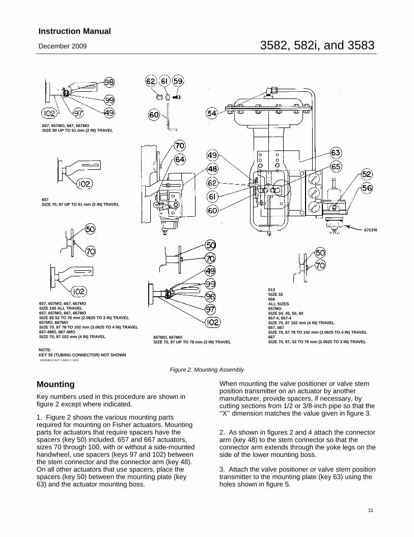
41B8569-D SHT 1 AND 2 / DOC
657, 657MO, 667, 667MOSIZE 80 UP TO 51 mm (2 IN) TRAVEL
657SIZE 70, 87 UP TO 51 mm (2 IN) TRAVEL
67CFR
657, 657MO, 667, 667MOSIZE 100 ALL TRAVEL657, 657MO, 667, 667MOSIZE 80 52 TO 76 mm (2.0625 TO 3 IN) TRAVEL657MO, 667MOSIZE 70, 87 78 TO 102 mm (3.0625 TO 4 IN) TRAVEL657-4MO, 667-4MOSIZE 70, 87 102 mm (4 IN) TRAVEL 657MO, 667MO
SIZE 70, 87 UP TO 78 mm (3 IN) TRAVEL
513SIZE 32656ALL SIZES657MOSIZE 34, 45, 50, 60657-4, 667-4SIZE 70, 87 102 mm (4 IN) TRAVEL657, 667SIZE 70, 87 78 TO 102 mm (3.0625 TO 4 IN) TRAVEL667SIZE 70, 87, 52 TO 78 mm (2.0625 TO 3 IN) TRAVEL
NOTE:KEY 55 (TUBING CONNECTOR) NOT SHOWN
Figure 2. Mounting Assembly
MountingKey numbers used in this procedure are shown infigure 2 except where indicated.
1. Figure 2 shows the various mounting partsrequired for mounting on Fisher actuators. Mountingparts for actuators that require spacers have thespacers (key 50) included. 657 and 667 actuators,sizes 70 through 100, with or without a side-mountedhandwheel, use spacers (keys 97 and 102) betweenthe stem connector and the connector arm (key 48).On all other actuators that use spacers, place thespacers (key 50) between the mounting plate (key63) and the actuator mounting boss.
When mounting the valve positioner or valve stemposition transmitter on an actuator by anothermanufacturer, provide spacers, if necessary, bycutting sections from 1/2 or 3/8-inch pipe so that the‘‘X’’ dimension matches the value given in figure 3.
2. As shown in figures 2 and 4 attach the connectorarm (key 48) to the stem connector so that theconnector arm extends through the yoke legs on theside of the lower mounting boss.
3. Attach the valve positioner or valve stem positiontransmitter to the mounting plate (key 63) using theholes shown in figure 5.

3582, 582i, and 3583Instruction Manual
December 2009
12
Table 10. Fisher 3582 and 3583 Mounting Information
ACTUATOR MAXIMUMTRAVEL
MOUNTINGHOLES
SET NO.(1)
TRAVEL PINPOSITION(2)
ACTUATOR MAXIMUMTRAVEL
MOUNTINGHOLES
SET NO.(1)TRAVEL PINPOSITION(2)
TYPE SIZE mm Inch TYPE SIZE mm Inch 657 667
513 & 513R 2032
1919
0.750.75
22
NormalNormal
657 & 667Without
Side-MountedHandwheel
303440
191938
0.751.125
1.5
332
423
NormalNormalNormal
656304060
5189
102
23.54
444
InvertedInvertedInverted
45455060
19515151
0.75222
1111
4122
Inverted(3)
NormalNormalNormal
657-4 WithoutSide-Mounted
Handwheel70 102 4 3 Inverted 70
5152−76
78−102
22.0625-33.0625-4
233
121
NormalNormal
Inverted(4)
657-4 WithSide-Mounted
Handwheel
7087
102102
44
21
InvertedInverted
80 76 3 2 2 Normal
657-8
30344040
54547989
2.1252.1253.125
3.5
3333
NormalNormalNormalNormal
8751
52-7678-102
22.0625-33.0625-4
223
221
NormalNormal
Inverted(4)
464647
7910579
3.1254.1253.125
222
NormalNormalInverted
100 102 4 4 4 Inverted
476070
105105105
4.1254.1254.125
142
InvertedInvertedInverted
657 & 667With
Side-MountedHandwheel
344045
193851
0.751.52
211
224
NormalNormalNormal
667-4 WithoutSide-Mounted
Handwheel
7087
102102
44
11
NormalNormal
50607080
5151
10276
2243
4322
1122
Inverted(4)
Inverted(4)
InvertedNormal
87 7678−102
33.0625-4
22
21
NormalInverted
1. The indicated set number should be considered a reference point only, due to the variables related to making up the stem connection.2. Normal position is shown in figure 4.3. Travel pin position for 657 is normal.4. Travel pin position for 667 is normal.
4. Mount the 67CFR regulator:
� 3582 valve positioners (except 3582NS) and3583 valve stem position transmitters, mount theregulator on the integral boss on the bypass block.
� 3582NS valve positioners, use the mountingplate with provision for separately mounting the67CFR regulator. Separately mount the positionerand the regulator on the mounting plate.
� 3582i valve positioners, mount the regulatoron the integral boss that is part of the 582i converterhousing.
5. As shown in figure 5, the mounting bracket hasfour sets of holes for mounting the assembly to theactuator. Refer to table 10 to determine which set ofmounting holes to use, then attach the assembly tothe lower mounting pad on the actuator.
CAUTION
To avoid equipment damage, becertain the connector arm clears thevalve positioner or valve stem positiontransmitter case as the actuator movesthrough its complete stroke.
6. Position the actuator to its mid-travel positionusing a handwheel or manual loading regulator.
7. Slip the round end of the travel pin (key 60) intothe rotary shaft arm (key 2) slot as shown in figure 4.
8. Slide the square end of the travel pin into the pinholder and pin lock (keys 61 and 59). Place the pinlock and holder into the slot in the connector arm(key 48). Screw the cap nut (key 62) onto the pinlock (key 59), but do not tighten.
3582, 582i, and 3583Instruction Manual
December 2009
13
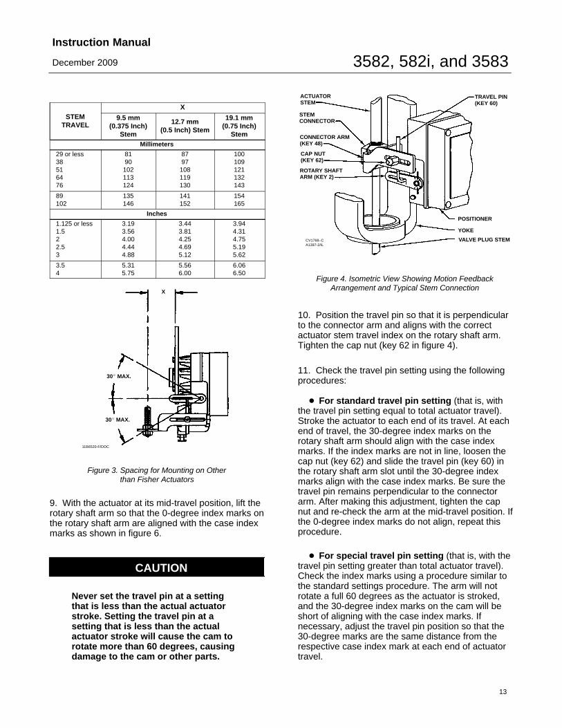
STEMTRAVEL
X
9.5 mm(0.375 Inch)
Stem
12.7 mm(0.5 Inch) Stem
19.1 mm(0.75 Inch)
StemMillimeters
29 or less38516476
8190102113124
8797108119130
100109121132143
89102
135146
141152
154165
Inches
1.125 or less1.522.53
3.193.564.004.444.88
3.443.814.254.695.12
3.944.314.755.195.62
3.54
5.315.75
5.566.00
6.066.50
11B6520-F/DOC
30� MAX.
30� MAX.
X
Figure 3. Spacing for Mounting on Otherthan Fisher Actuators
9. With the actuator at its mid-travel position, lift therotary shaft arm so that the 0-degree index marks onthe rotary shaft arm are aligned with the case indexmarks as shown in figure 6.
CAUTION
Never set the travel pin at a settingthat is less than the actual actuatorstroke. Setting the travel pin at asetting that is less than the actualactuator stroke will cause the cam torotate more than 60 degrees, causingdamage to the cam or other parts.
CV1768−CA1397-2/IL
ACTUATORSTEM
STEMCONNECTOR
CONNECTOR ARM(KEY 48)
CAP NUT(KEY 62)
ROTARY SHAFT ARM (KEY 2)
TRAVEL PIN(KEY 60)
POSITIONER
YOKE
VALVE PLUG STEM
Figure 4. Isometric View Showing Motion FeedbackArrangement and Typical Stem Connection
10. Position the travel pin so that it is perpendicularto the connector arm and aligns with the correctactuator stem travel index on the rotary shaft arm.Tighten the cap nut (key 62 in figure 4).
11. Check the travel pin setting using the followingprocedures:
� For standard travel pin setting (that is, withthe travel pin setting equal to total actuator travel).Stroke the actuator to each end of its travel. At eachend of travel, the 30-degree index marks on therotary shaft arm should align with the case indexmarks. If the index marks are not in line, loosen thecap nut (key 62) and slide the travel pin (key 60) inthe rotary shaft arm slot until the 30-degree indexmarks align with the case index marks. Be sure thetravel pin remains perpendicular to the connectorarm. After making this adjustment, tighten the capnut and re-check the arm at the mid-travel position. Ifthe 0-degree index marks do not align, repeat thisprocedure.
� For special travel pin setting (that is, with thetravel pin setting greater than total actuator travel).Check the index marks using a procedure similar tothe standard settings procedure. The arm will notrotate a full 60 degrees as the actuator is stroked,and the 30-degree index marks on the cam will beshort of aligning with the case index marks. Ifnecessary, adjust the travel pin position so that the30-degree marks are the same distance from therespective case index mark at each end of actuatortravel.

3582, 582i, and 3583Instruction Manual
December 2009
14
BF2635-B/DOC
MOUNTING PLATE FOR MOUNTING POSITIONERWITH INTEGRALLY MOUNTED FILTER REGULATOR
MOUNTING PLATE FOR MOUNTING POSITIONER WITHSEPARATELY MOUNTED FILTER REGULATOR
HOLES FOR MOUNTINGPLATE TO ACTUATOR
HOLES FOR MOUNTINGPOSITIONER TO PLATE
SET NO. 1
SET NO. 2
SET NO. 3
SET NO. 4HOLES FORMOUNTING REGULATOR
HOLES FOR MOUNTINGPLATE TO ACTUATOR
HOLES FOR MOUNTINGPOSITIONER TO PLATE
Figure 5. Mounting Plates Used with Fisher 3582 Valve Positioners and 3583 Valve Stem Position Transmitters
70CA0750-CA2452-2/IL
CASE INDEX MARKS
30 DEGREES
30 DEGREES 30-DEGREEARM INDEXMARKS
0-DEGREEARM INDEXMARKS
ARM AT MID-TRAVEL POSITION
ACTUATOR STEM TRAVEL INDEXESNOTES:
MAXIMUM ROTATION FROM MID-TRAVEL POSITION.ALIGN INDEX MARKS AS SHOWN FOR MID-TRAVEL POSITION.
Figure 6. Rotary Shaft Arm and Case Index Marks
Changing Cam PositionRefer to figure 20 for a typical cam illustration andkey number locations.
Note
� For Valve Positioners: The smallarrow on the cam must point in thedirection of stem movement withincreasing actuator diaphragmpressure.
� For Valve Stem PositionTransmitters: If the arrow on the campoints up toward the nozzle, outputpressure increases with downwardstem movement. If the arrow pointsdown, output pressure decreases withdownward stem movement.
If the arrow is pointing in the wrongdirection, use the following procedureto remove, reverse, and re-install thecam.
When mounting a valve positioner or valve stemposition transmitter, check to see if the correct cam(key 4) and cam position has been selected. Tochange the cam or cam position, unhook theextension spring (key 38), and remove the cam boltand locking nut (keys 6 and 45). Remove the camand spring retainer bracket (key 43).
To install the cam, screw the locking nut all the wayonto the cam bolt. Attach the cam and springretainer bracket to the shaft assembly with the cambolt. Tighten the bolt to secure the cam. Then,tighten the locking nut against the spring retainerbracket. Hook the spring into the spring retainerbracket.
Details on cam characteristics can be found in thecam information portion of the operating informationsection.

3582, 582i, and 3583Instruction Manual
December 2009
15
Pressure Connections
WARNING
Valve positioners and valve stemposition transmitters are capable ofproviding full supply pressure toconnected equipment. To avoidpersonal injury or equipment damagecaused by parts bursting from systemoverpressure, make sure the supplypressure never exceeds the maximumsafe working pressure of anyconnected equipment.
Pressure connections are shown in figure 7. Allpressure connections are 1/4 NPT internal. Use3/8-inch tubing for all pressure connections. Aftermaking pressure connections, turn on the supplypressure and check all connections for leaks.
Supply Connection
WARNING
Personal injury or property damagemay occur from an uncontrolledprocess if the supply medium is notclean, dry, oil-free air, or noncorrosivegas. While use and regularmaintenance of a filter that removesparticles larger than 40 micrometers indiameter will suffice in mostapplications, check with an EmersonProcess Management field office andindustry instrument air qualitystandards for use with corrosive air orif you are unsure about the properamount or method of air filtration orfilter maintenance.3582i does not meet third partyapprovals for use with natural gas asthe supply medium. Use of natural gasas the supply medium can result inpersonal injury or property damagefrom fire or explosion.
CAUTION
Use a clean, dry, oil-free air supplywith instruments containing EPDMcomponents. EPDM is subject to
degradation when exposed topetroleum-based lubricants.
Supply pressure must be clean, dry, oil-free air ornoncorrosive gas. Use a 67CFR filter regulator withstandard 5 micrometer filter, or equivalent, to filterand regulate supply air. Except for the 3582NS, thefilter regulator can be mounted on the positioner. Forthe 3582NS the regulator can be mounted on themounting plate with the positioner but not on thepositioner. The supply pressure should be highenough to permit setting the regulator 0.3 bar (5 psi)above the upper limit of the appropriate pressurerange, for example: 1.4 bar (20 psig) for a 0.2 to 1.0bar (3 to 15 psig) range. However, do not exceed themaximum allowable supply pressure of 3.4 bar (50psig) nor the pressure rating of any connectedequipment.
Connect the nearest suitable supply source to the1/4 NPT IN connection on the filter regulator (iffurnished) or to the 1/4 NPT SUPPLY connection onthe positioner block assembly.
Output Connection
A factory mounted valve positioner has the valvepositioner output piped to the supply connection onthe actuator. If mounting the valve positioner in thefield, connect 3/8-inch tubing between the 1/4 NPTvalve positioner connection marked OUTPUT andthe actuator supply pressure connection. Connectthe valve stem position transmitter connectionmarked OUTPUT to an instrument that indicatesvalve stem position.
Instrument Connection
For a 3582 pneumatic valve positioner connect3/8-inch tubing from the control device to the 1/4NPT INSTRUMENT connection. If the control deviceis mounted on the control valve assembly by thefactory, this connection is made.

3582, 582i, and 3583Instruction Manual
December 2009
16
11B6519-G11B6520-FC0775-1/IL
246.1(9.69)
182.6(7.19)
141.2(5.56)
119.1(4.69)
7.9(.31)
289.0(11.38)
8.6 (.34) ∅ HOLESSPACED 17.5 (.69) APART
139.7(5.50)
57.2(2.25)
12.7(.50)
261(10.26)
141.2(5.56)
127.0(5.00)
7.9(.31)
204.7(8.06)
139.7(5.50)
57.2(2.25)
12.7(.50)
mm(INCH)
8.6 (.34) ∅ HOLESSPACED 17.5 (.69) APART
3582(DIMENSIONS FOR 3582A, C, D, AND G ARE THE SAME)
CL OF ACTUATOR
1/4-18 NPTOUTLET CONNPLUGGED
1/4-18 NPTOUTPUT CONN
1/4-18 NPTSUPPLY CONN
1/4-18 NPTOPTIONAL OUTPUTCONN PLUGGED
3/8-18 NPTVENT CONN
1/2-14 NPTCONDUIT CONN
1/4-18 NPTOUTLET CONNPLUGGED
1/4-18 NPTSUPPLY CONN
3/8-18 NPTVENT CONN
1/4-18 NPTOUTPUT CONN
CL OF ACTUATOR
3582i
1/4-18 NPTOUTPUT CONN
Figure 7. Typical Dimensions and Connections
The 3582i electro-pneumatic valve positionerrequires a 4-20 milliampere DC current input signalfrom the control device. A 1/2 NPT conduitconnection is provided for properly wiring electricalinstallations. For more information, see the electricalconnections section.
Diagnostic ConnectionsTo support diagnostic testing ofvalve/actuator/positioner/accessory packages,
special connectors and hardware are available. Thehardware used includes 1/8 NPT connector bodiesand body protectors. If the diagnostic connectors areordered for a positioner with gauges, 1/8-inch stemsare also included.
Install the connectors on the 3582 block assembly or582i housing as shown in figure 8. Before installingthe connectors on the positioner, apply sealant tothe threads. Sealant is provided with the diagnosticconnections and hardware.

3582, 582i, and 3583Instruction Manual
December 2009
17
12B8045-AA6077−1/IL 12B8046-C
A6078−2/IL
STEM PROVIDEDWHEN GAUGE IS SPECIFIED
GAUGE
3582i
BODY PROTECTOR
BODY
3582i VALVE POSITIONER3582 VALVE POSITIONERS
3582 POSITIONERS
BODY PROTECTOR
BODY
Figure 8. Diagnostic Connections
Vent
WARNING
Personal injury or property damagecould result from fire or explosion ofaccumulated gas if a flammable gas isused as the supply pressure mediumand the positioner/actuator is in anenclosed area. The positioner/actuatorassembly does not form a gas-tightseal, and when the assembly isenclosed, a remote vent line, adequateventilation, and necessary safetymeasures should be used. For leakagerates, see the Maximum Steady-StateAir Consumption specification. Aremote vent pipe alone cannot berelied upon to remove all hazardousgas. Vent line piping should complywith local and regional codes andshould be as short as possible withadequate inside diameter and fewbends to reduce case pressurebuildup.
WARNING
3582i does not meet third partyapprovals for use with natural gas as
the supply medium. Use of natural gasas the supply medium can result inpersonal injury or property damagefrom fire or explosion.
CAUTION
When installing a remote vent pipe,take care not to overtighten the pipe inthe vent connection. Excessive torquewill damage the threads in theconnection.
The vent opening at the back of the case markedVENT should be left open to prevent pressurebuildup inside the case and to provide a drain holefor any moisture that might collect inside the case.The perforated section of the nameplate normallycovers this opening to prevent blockage from debrisor insects. Also, ensure the exhaust holes in therelay (key 32 in figure 20) are kept open.
If a remote vent is required, the vent line must be asshort as possible with a minimum number of bendsand elbows. The vent connection is 3/8 NPT internal.Use 3/8-inch or larger tubing to provide a remotevent. The 582i has a 1/4 NPT internal ventconnection. Use optional remote vent 83L relay forremote vent applications.

3582, 582i, and 3583Instruction Manual
December 2009
18
A3875*/IL
FIELD WIRING
EARTHGROUND
NOTES:FOR TROUBLESHOOTING OR MONITORING OPERATION,
AN INDICATING DEVICE CAN BE A VOLTMETER ACROSS A250 OHM RESISTOR OR A CURRENT METER.
CONTROLDEVICE
POSITIONERHOUSING
TERMINALBLOCK
Figure 9. Typical Field Wiring Diagram
Electrical Connections for 3582i ValvePositioner
WARNING
For explosion-proof applications,disconnect power before removing theconverter housing cap.
For Class I, Division 1 explosion-proofapplications, install rigid metal conduitand a conduit seal no more than 457mm (18 inches) from the converter.Personal injury or property damagemight result from explosion if the sealis not installed.
For intrinsically safe installations, referto the loop schematics shown infigures 28 and 30, factory drawings, orto instructions provided by the barriermanufacturer for proper wiring andinstallation.
21B2335-DA6012/IL
Figure 10. Input Equivalent Circuit for Fisher 582i Converter
A7140 / IL
CONVERTERHOUSING
I/P MODULE
FIELDWIRINGCONNECTION
Figure 11. Wiring Connections for Fisher 582i Converter
Select wiring and/or cable glands thatare rated for the environment of use(such as hazardous area, ingressprotection and temperature). Failure touse properly rated wiring and/or cableglands can result in personal injury orproperty damage from fire orexplosion.
Wiring connections must be inaccordance with local, regional, andnational codes for any givenhazardous area approval. Failure tofollow the local, regional, and nationalcodes could result in personal injuryor property damage from fire orexplosion.
Use the 1/2 NPT conduit connection on the 582iconverter housing for installation of field wiring. ForClass I, Division I explosion-proof applications,install rigid metal conduit and a seal no more than457 mm (18 inches) from the converter. Also, install
3582, 582i, and 3583Instruction Manual
December 2009
19
conduit according to local and national electricalcodes which apply to the application.
Refer to figures 9, 10 and 11 when connecting fieldwiring from the control device to the converter.Connect the positive wire from the control device tothe converter positive (+) terminal, and the negativewire from the control device to the converternegative (−) terminal. Do not overtighten the terminalscrews. Maximum torque is 0.45 N�m (4 lbf�in.).Connect the converter grounding terminal to anearth ground.
582i Converter Installation
Note
Contact your Emerson ProcessManagement sales office forapplication information beforeupgrading an existing 3582 valvepositioner by field installation of a 582ielectro-pneumatic converter.
WARNING
Avoid personal injury from suddenrelease of process pressure. Beforemounting the 582i converter:
� Always wear protective clothing,gloves, and eyewear when performingany maintenance operations.
� Do not remove the actuator fromthe valve while the valve is stillpressurized.
� Disconnect any operating linesproviding air pressure or a controlsignal to the actuator. Be sure theactuator cannot suddenly open orclose the valve.
� Use bypass valves or completelyshut off the process to isolate thevalve from process pressure. Relieveprocess pressure on both sides of thevalve.
� Vent actuator loading pressure.
� Use lock-out procedures to besure that the above measures stay ineffect while you work on theequipment.
� Do not open when an explosivedust atmosphere is present.
� Check with your process or safetyengineer for any additional measuresthat must be taken to protect againstprocess media.
Note
Before planning to retrofit an installed3582 positioner, refer to the positionermounting plate illustrations shown infigure 5. Mounting plates with athree-hole mounting pattern(positioner to mounting plate) cannotsupport a 582i converter. Do notattempt to mount a 582i converter onan existing 3582 positioner which hasa three-hole mounting pattern.
Isolate the control valve from the line pressure, andrelease pressure from both sides of the valve body.Use lock-out procedures to be sure that the abovemeasures stay in effect while you work on theequipment.
If a 3582 pneumatic valve positioner has previouslybeen installed using a mounting plate with afive-hole mounting pattern (positioner to mountingplate), either at the factory or in the field, it can beupgraded to a 3582i electro-pneumatic valvepositioner by installation of a 582i converter. Toinstall a 582i converter, refer to the followinginstructions.
Note
Inspect the existing valve positioner todetermine the input signal range. If theinput signal range is not 0.2 to 1.0 bar(3 to 15 psig), refer to the appropriatesections of this manual describinginput signal ranges and how to changethe range spring.
1. Inspect the positioner mounting plate. Be certainthat five screws fasten the positioner to the mountingplate. Two additional screws fasten the plate to theactuator.
When the positioner is correctly attached to themounting plate, proceed with the installation bytaking the control valve/actuator/positioner packageout of service.
2. Properly vent the actuator loading pressure andthe supply pressure. Disconnect the pressure tubingconnections to the valve positioner.

3582, 582i, and 3583Instruction Manual
December 2009
20
3. Remove the two screws (key 105 in figures 24 or 25) holding the bypass block (key 34A in figures24 or 25) to the valve positioner case and removethe bypass block. Save the screws to reattach the582i converter.
4. Remove and discard the existing gasket (key 104in figures 24 or 25) between the bypass block andvalve positioner case.
5. Unpack the 582i converter to be installed.
6. Position the new gasket on the 582i converter asshown in figure 26. Insert the existing screws (key105 in figures 24 or 25) through the appropriateholes in the 582i converter housing and new gasket.
7. Mate the converter and new gasket to the side ofthe valve positioner case using the alignment pinson the converter housing.
8. Tighten the screws.
9. Reconnect the pressure connections according tothe instructions given in the pressure connectionssection of this manual.
10. Make the electrical connections according to theinstructions given in the electrical connectionssection of this manual.
11. Complete the standard calibration proceduredescribed in the calibration section of this manual.
12. Return the control valve package to service.
Operating InformationInstructions for setting the zero and span are foundin the calibration section.
Valve Positioner Cam Information
Note
The small arrow on the valvepositioner cam must point in thedirection of stem movement withincreasing actuator diaphragmpressure. If the arrow is pointing in thewrong direction, remove, reverse, andre-install the cam. Refer to theChanging Cam Position section of thismanual.
Refer to figure 20 for key number locations. Unhookthe spring (key 38), and remove the cam bolt andlocking nut (keys 6 and 45). Remove the cam (key 4)and spring retainer bracket (key 43). To install the
CK4832-A / DOC
PERCENT VALVE STEM TRAVEL0 PERCENT CORRESPONDS TOMINIMUM DIAPHRAGM PRESSURE
CAMC
CAMA
CAMB
PE
RC
EN
T IN
ST
RU
ME
NT
PR
ES
SU
RE
SP
AN
RE
VE
RS
EA
CT
ING
PO
SIT
ION
ER
DIR
EC
TA
CT
ING
PO
SIT
ION
ER
Figure 12. Cam Characteristic Curves
cam, screw the locking nut all the way onto the cambolt. Attach the cam and spring retainer bracket withthe cam bolt. Tighten the bolt to secure the cam.Then, tighten the locking nut against the springretainer bracket. Hook the spring into the springretainer bracket.
When shipped from the factory, 3582 valvepositioners and the 3582i valve positioner have alinear cam, Cam A, installed in the operatingposition. Two characterized cams, Cams B and C,are available. These characterized cams may beused to modify the valve flow characteristics.
Figure 12 shows resultant stem travel due to anincremental instrument pressure change for eachcam. In figure 12, the curves are based on 60degrees cam rotation for 100 percent stem travel. At50 percent of the input signal span, for example, thestem will travel 50 percent with cam A, 68 percentwith cam B, and 32 percent with cam C. Figure 13shows how the flow characteristics change whenusing the cams with a valve that has equalpercentage characteristics. Figure 14 shows how theflow characteristics change when using the camswith a valve that has linear characteristics.

3582, 582i, and 3583Instruction Manual
December 2009
21
CK4835-A / DOC
PE
RC
EN
T IN
ST
RU
ME
NT
PR
ES
SU
RE
SP
AN
INSTRUMENT PRESSURE - FLOWCHARACTERISTIC WITH EQUALPERCENTAGE VALVE PLUG ATCONSTANT PRESSURE DROP
PERCENT FLOW
NORMALLYCLOSEDVALVE
NORMALLYOPENVALVE
RE
VE
RS
EA
CT
ING
PO
SIT
ION
ER
DIR
EC
TA
CT
ING
PO
SIT
ION
ER
CAMA
CAMB
CAMC
CAMC
CAMA
CAMB
Figure 13. Flow Characteristics with Different Cams andEqual Percentage Valve Plug
CK4833-A / DOC
INSTRUMENT PRESSURE - FLOWCHARACTERISTIC WITH LINEARVALVE PLUG AT CONSTANT PRESSURE DROP
NORMALLYCLOSEDVALVE
CAMA
CAMB
CAMC
CAMA
CAMB
PE
RC
EN
T IN
ST
RU
ME
NT
PR
ES
SU
RE
SP
AN
PERCENT FLOW
NORMALLYOPENVALVE
RE
VE
RS
EA
CT
ING
PO
SIT
ION
ER
DIR
EC
TA
CT
ING
PO
SIT
ION
ER
CAMC
Figure 14. Flow Characteristics with Different Cams andLinear Valve Plug
When cam A is the operating cam, there is a linearrelationship between an incremental instrumentpressure change and the resultant valve stem travel.The flow characteristic is that of the control valve.Installing either cam B or C as the operating cam
changes the relationship between the incrementalinstrument pressure change and valve stem travel,thereby modifying the valve flow characteristic.
Valve Stem Position Transmitter CamInformation
Note
If the small arrow on the valve stemposition transmitter cam points uptoward the nozzle, output pressureincreases with downward stemmovement. If the arrow points down,output pressure decreases withdownward stem movement. If thearrow is pointing in the wrongdirection, remove, reverse, andre-install the cam. Refer to theChanging Cam Position section of thismanual.
Refer to figure 20 for key number locations. Unhookthe spring (key 38), and remove the cam bolt andlocking nut (keys 6 and 45). Remove the cam (key 4)and spring retainer bracket (key 43). To install thecam, screw the locking nut all the way onto the cambolt. Attach the cam and spring retainer bracket withthe cam bolt. Tighten the bolt to secure the cam.
Then, tighten the locking nut against the springretainer bracket. Hook the spring into the springretainer bracket.
The linear cam is the only cam available for the 3583valve stem position transmitter. There is always alinear relationship between stem travel and the stemposition transmitter output.
Valve Positioner Bypass Operation3582 and 3582D valve positioners, and 3582NSpositioners with bypass, are supplied with a bypassassembly. A handle on the bypass assembly permitsselecting positioner or bypass operation. Refer tofigure 24 for key number locations.
CAUTION
Do not use bypass when the valvepositioner is reverse-acting or is insplit-range operation. In these cases,

3582, 582i, and 3583Instruction Manual
December 2009
22
Table 11. Standard Instrument Input Signals and Range Springs
INSTRUMENT INPUTSIGNAL RANGE STANDARD SPAN
ALLOWABLE INPUT SIGNAL(1) RANGE SPRINGCOLOR
RANGE SPRING PARTNUMBERMinimum Maximum
0.2−1.0 bar (3−15 psig) 0.8 bar (12 psig) 0.07 bar (1 psig) 1.4 bar (21 psig)Silver 1V621727012
4−20 mA(2) 16 mA 2 mA 22 mA
0.4−2.0 bar (6−30 psig) 1.6 bar (24 psig) 0.07 bar (1 psig) 2.4 bar (35 psig) Red 1V6219270121. Minimum and maximum allowable input signals ensure functional operation.2. For 3582i only.
bypassing the valve positioner sendsthe input signal directly to theactuator. Such a change will affect thedesired operation and possibly upsetthe system. Use bypass only when theinput signal range is the same as thevalve positioner output range requiredfor normal actuator operation.
Labels on the bypass block (key 34A) and a pointeron the bypass handle (key 34D) indicate if the inputsignal from the instrument goes to the positioner ordirectly to the control valve actuator. Push thebypass handle toward the back of the positioner tomove the pointer over the word POSITIONER. Withthe bypass handle in this position, the input signalgoes to the valve positioner bellows and the outputpressure of the valve positioner goes to the actuator.Pull the bypass handle forward to move the pointerover the word BYPASS. In this position, the inputsignal goes directly to the actuator.
Note
A difference between the input signalpressure and the valve positioneroutput pressure could cause atransient bump in the controlledsystem when the bypass handle ismoved to BYPASS.
With a reverse-acting or split-range valve positioner,the bypass handle may be locked in thePOSITIONER position so that bypass cannot beused. To lock the bypass handle in thePOSITIONER position, first shut off the instrumentand supply pressure to the valve positioner. Then,remove the hex head shoulder screw from the centerof the handle. Remove the handle and rotate it 180degrees and re-install it with the handle between thetwo lugs cast on the bypass block. Replace theshoulder screw.
Input Signal Ranges
Standard input signal ranges for valve positionersand valve stem position transmitters are shown intable 11. Changing from one standard range toanother requires changing the range spring. Tochange the range spring, refer to the instructions forchanging the range spring in the maintenancesection of this manual. Split-range operation of 3582valve positioners or the 3582i valve positionernormally does not require changing the spring. Referto the section below for split-range information.
Valve Positioner Split-Range Operation
3582 valve positioners and the 3582i valvepositioner are suitable for split-range operations. Insplit-range operation, the input signal, eitherpneumatic or DC current, from a single controldevice is split between two or more control valves.No additional parts are required to use an existingvalve positioner for split-range operation.
Table 12 shows some typical split-ranges for thevalve positioners.
To change to split-range operation, perform thebeam alignment procedures then perform thecalibration procedure using the desired split rangeinputs that result in full valve travel. For example, fora 3582 positioner with a 0.2 to 1.0 bar (3 to 15 psig)input signal range in a two-way split, a 0.6 bar (9psig) input signal should completely stroke the valvefor a 0.2 to 0.6 bar (3 to 9 psig) signal range.

3582, 582i, and 3583Instruction Manual
December 2009
23
Table 12. Split-Range Capabilities3582 POSITIONERS
Split0.2 to 1.0 Bar or 3 to 15
Psig Input Signal0.4 to 2.0 Bar or 6 to 30
Psig Input Signal
Bar Psig Bar Psig
Two-way 0.2 to 0.60.6 to 1.0
3 to 99 to 15
0.4 to 1.21.2 to 2.0
6 to 1818 to 30
Three-way0.2 to 0.50.5 to 0.70.7 to 1.0
3 to 77 to 11
11 to 15
0.4 to 0.90.9 to 1.51.5 to 2.0
6 to 1414 to 2222 to 30
3582i POSITIONER
Split 4-20 Milliampere Input Signal
Two-way 4 to 1212 to 20
Three-way4 to 9.3
9.3 to 14.714.7 to 20
Note
The flapper must approach the nozzlesquarely at the midpoint value of theinput signal range for properoperation.
On some applications where the inputsignal span is comparatively small (asfound with split-range applications),the nozzle adjustment may not beenough to set the proper startingpoint. Also, some difficulty may beexperienced in keeping a valvepositioner from unloading when theinput signal continues to increaseabove the split-range.
For example, for a 0.2 to 0.6 bar (3 to 9psig) input signal range, the inputsignal could increase to 1.0 bar (15psig). Continued bellows travel due tothe increased input signal over thesplit-range would drive the flapper intothe nozzle. The impact could possiblycause misalignment between theflapper and nozzle. Such amisalignment, in turn, could affectsplit-range calibration.
In these cases, adjust the followerassembly screw in addition to thenozzle adjustment to obtainsatisfactory results.
Note
3582 valve positioners require arelatively small percentage of theinstrument pressure span to obtain fullvalve travel. With the travel pin set toequal the valve travel, the input signalchange required to fully stroke thevalve can be reduced to 33 percent ofnormal input signal change. With thetravel pin set to a value greater thanthe valve travel, the input signalchange required to fully stroke thevalve can be reduced to a minimum of20 percent of normal input signalchange.
Changing Valve Positioner Action
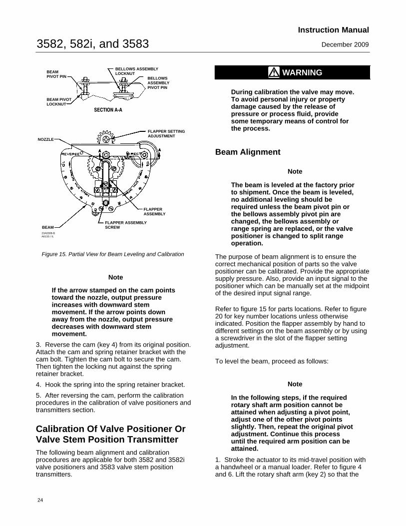
Converting a 3582 valve positioner or 3582i valvepositioner from direct acting (an increasing inputsignal, either pneumatic or electrical, increasesoutput pressure) to reverse acting (increasing inputsignal decreases output pressure) or vice versarequires no additional parts. The position of theflapper assembly on the beam determines theaction. As shown in figure 15, the beam is dividedinto quadrants. The direct-acting quadrant of thebeam is labeled DIRECT and the reverse-actingquadrant is labeled REVERSE. To change thepositioner action, simply move the flapper assemblyto the opposite quadrant of the beam. Perform thecalibration procedures in the valve positionercalibration section.
Changing Valve Stem PositionTransmitter Action
Refer to figure 20 for key number locations unlessotherwise indicated.
The flapper of the 3583 valve stem positiontransmitter is always positioned in the reverse-actingquadrant as shown in figure 19. To reverse thesignal, reverse the cam as follows:
1. Unhook the spring (key 38), and remove the cambolt (key 6), cam (key 4), and spring retainer bracket(key 43).
2. Screw the locking nut (key 45) all the way ontothe cam bolt.
3582, 582i, and 3583Instruction Manual
December 2009
24
23A0308-BA6133 / IL
BEAMPIVOT PIN
BEAM
NOZZLE
BEAM PIVOTLOCKNUT
BELLOWS ASSEMBLYLOCKNUT
BELLOWSASSEMBLYPIVOT PIN
FLAPPER SETTINGADJUSTMENT
FLAPPERASSEMBLY
FLAPPER ASSEMBLYSCREW
SECTION A‐A
Figure 15. Partial View for Beam Leveling and Calibration
Note
If the arrow stamped on the cam pointstoward the nozzle, output pressureincreases with downward stemmovement. If the arrow points downaway from the nozzle, output pressuredecreases with downward stemmovement.
3. Reverse the cam (key 4) from its original position.Attach the cam and spring retainer bracket with thecam bolt. Tighten the cam bolt to secure the cam.Then tighten the locking nut against the springretainer bracket.
4. Hook the spring into the spring retainer bracket.
5. After reversing the cam, perform the calibrationprocedures in the calibration of valve positioners andtransmitters section.
Calibration Of Valve Positioner OrValve Stem Position TransmitterThe following beam alignment and calibrationprocedures are applicable for both 3582 and 3582ivalve positioners and 3583 valve stem positiontransmitters.
WARNING
During calibration the valve may move.To avoid personal injury or propertydamage caused by the release ofpressure or process fluid, providesome temporary means of control forthe process.
Beam Alignment
Note
The beam is leveled at the factory priorto shipment. Once the beam is leveled,no additional leveling should berequired unless the beam pivot pin orthe bellows assembly pivot pin arechanged, the bellows assembly orrange spring are replaced, or the valvepositioner is changed to split rangeoperation.
The purpose of beam alignment is to ensure thecorrect mechanical position of parts so the valvepositioner can be calibrated. Provide the appropriatesupply pressure. Also, provide an input signal to thepositioner which can be manually set at the midpointof the desired input signal range.
Refer to figure 15 for parts locations. Refer to figure20 for key number locations unless otherwiseindicated. Position the flapper assembly by hand todifferent settings on the beam assembly or by usinga screwdriver in the slot of the flapper settingadjustment.
To level the beam, proceed as follows:
Note
In the following steps, if the requiredrotary shaft arm position cannot beattained when adjusting a pivot point,adjust one of the other pivot pointsslightly. Then, repeat the original pivotadjustment. Continue this processuntil the required arm position can beattained.
1. Stroke the actuator to its mid-travel position witha handwheel or a manual loader. Refer to figure 4and 6. Lift the rotary shaft arm (key 2) so that the
3582, 582i, and 3583Instruction Manual
December 2009
25
1
1
NOTE:ALIGN INDEX MARKS AS SHOWN FOR MID-TRAVEL POSITION.
A2452-3 / IL
CASE INDEX MARKS
0-DEGREEARM INDEXMARKS
ARM AT MID-TRAVEL POSITION
ACTUATOR STEM TRAVEL INDEXES
Figure 16. Rotary Shaft Arm 0-Degree and Case Index Marks,Location and Alignment
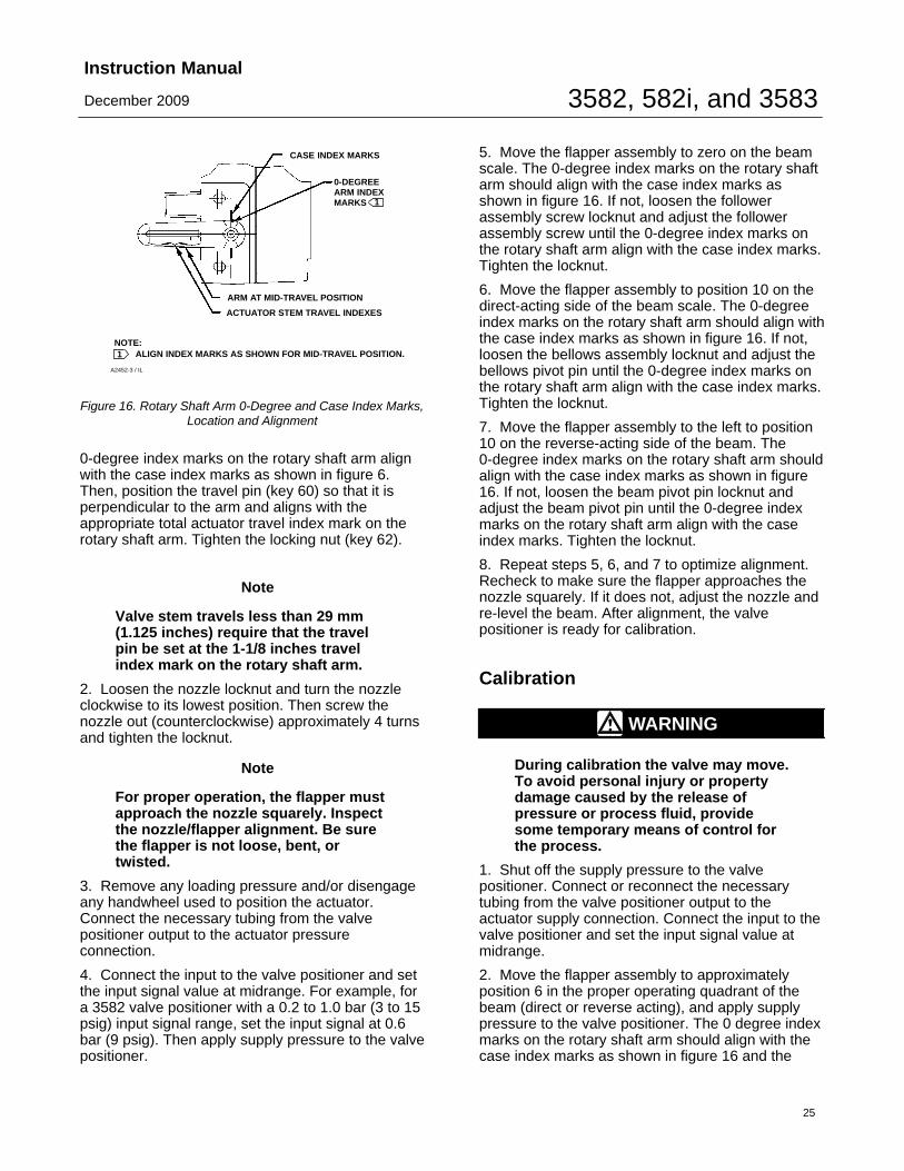
0-degree index marks on the rotary shaft arm alignwith the case index marks as shown in figure 6.Then, position the travel pin (key 60) so that it isperpendicular to the arm and aligns with theappropriate total actuator travel index mark on therotary shaft arm. Tighten the locking nut (key 62).
Note
Valve stem travels less than 29 mm(1.125 inches) require that the travelpin be set at the 1-1/8 inches travelindex mark on the rotary shaft arm.
2. Loosen the nozzle locknut and turn the nozzleclockwise to its lowest position. Then screw thenozzle out (counterclockwise) approximately 4 turnsand tighten the locknut.
Note
For proper operation, the flapper mustapproach the nozzle squarely. Inspectthe nozzle/flapper alignment. Be surethe flapper is not loose, bent, ortwisted.
3. Remove any loading pressure and/or disengageany handwheel used to position the actuator.Connect the necessary tubing from the valvepositioner output to the actuator pressureconnection.
4. Connect the input to the valve positioner and setthe input signal value at midrange. For example, fora 3582 valve positioner with a 0.2 to 1.0 bar (3 to 15psig) input signal range, set the input signal at 0.6bar (9 psig). Then apply supply pressure to the valvepositioner.
5. Move the flapper assembly to zero on the beamscale. The 0-degree index marks on the rotary shaftarm should align with the case index marks asshown in figure 16. If not, loosen the followerassembly screw locknut and adjust the followerassembly screw until the 0-degree index marks onthe rotary shaft arm align with the case index marks.Tighten the locknut.
6. Move the flapper assembly to position 10 on thedirect-acting side of the beam scale. The 0-degreeindex marks on the rotary shaft arm should align withthe case index marks as shown in figure 16. If not,loosen the bellows assembly locknut and adjust thebellows pivot pin until the 0-degree index marks onthe rotary shaft arm align with the case index marks.Tighten the locknut.
7. Move the flapper assembly to the left to position10 on the reverse-acting side of the beam. The0-degree index marks on the rotary shaft arm shouldalign with the case index marks as shown in figure16. If not, loosen the beam pivot pin locknut andadjust the beam pivot pin until the 0-degree indexmarks on the rotary shaft arm align with the caseindex marks. Tighten the locknut.
8. Repeat steps 5, 6, and 7 to optimize alignment.Recheck to make sure the flapper approaches thenozzle squarely. If it does not, adjust the nozzle andre-level the beam. After alignment, the valvepositioner is ready for calibration.
Calibration
WARNING
During calibration the valve may move.To avoid personal injury or propertydamage caused by the release ofpressure or process fluid, providesome temporary means of control forthe process.
1. Shut off the supply pressure to the valvepositioner. Connect or reconnect the necessarytubing from the valve positioner output to theactuator supply connection. Connect the input to thevalve positioner and set the input signal value atmidrange.
2. Move the flapper assembly to approximatelyposition 6 in the proper operating quadrant of thebeam (direct or reverse acting), and apply supplypressure to the valve positioner. The 0 degree indexmarks on the rotary shaft arm should align with thecase index marks as shown in figure 16 and the

3582, 582i, and 3583Instruction Manual
December 2009
26
actuator should be at its midtravel position. If not,first check for loose linkage or improper caminstallation. A minor nozzle height adjustment mightbe necessary to make the desired input signal valuecorrespond to the starting point of travel.
3. Apply an input signal equal to the low value of theinput signal range. For example, for a 3582 valvepositioner with a 0.2 to 1.0 bar (3 to 15 psig) inputsignal range, set the input signal at 0.2 bar (3 psig).Loosen the nozzle locknut and adjust the nozzle untilthe actuator moves to the proper end of its travel.Changing the nozzle position is intended only as ameans of zero trim adjustment. Whenever nozzleposition is changed, the zero reference point ischanged.
4. Apply an input signal equal to the high value ofthe input signal range and observe the actuator stemtravel. If the stem travel is short of its expectedrange, increase the travel by moving the flapperassembly to a higher number on the beam. If thedesired stem travel occurs before the input signalreaches the high value of the input signal range,decrease the travel by moving the flapper assemblytoward a lower number on the beam.
5. Repeat steps 3 and 4 until the correct travel isachieved. Each time the flapper position is changedin step 4, repeat step 3 to provide proper zero.
Moving the flapper assembly toward zero on thebeam scale decreases stem travel. Table 13 lists theminimum stem travel available for different travel pinsettings. For example, with a travel pin setting of 2the minimum stem travel possible, for the full inputsignal range, would be 11 mm (0.4375 inch).
Note
The positioner will fully vent orpressurize the actuator to supplypressure at the ends of actuator travelwhen the positioner is calibratedcorrectly. Failure to properly calibratethe positioner may result in reducedseat loading.
Table 13. Minimum Travel with Given Pin PositionTRAVEL PIN
POSITION ALONGROTARY SHAFT ARM
MINIMUM TRAVEL AVAILABLE
mm Inch
1-1/81-1/2
2
68
11
0.250.31250.4375
2-1/234
131622
0.50.6250.875
Principle of Operation
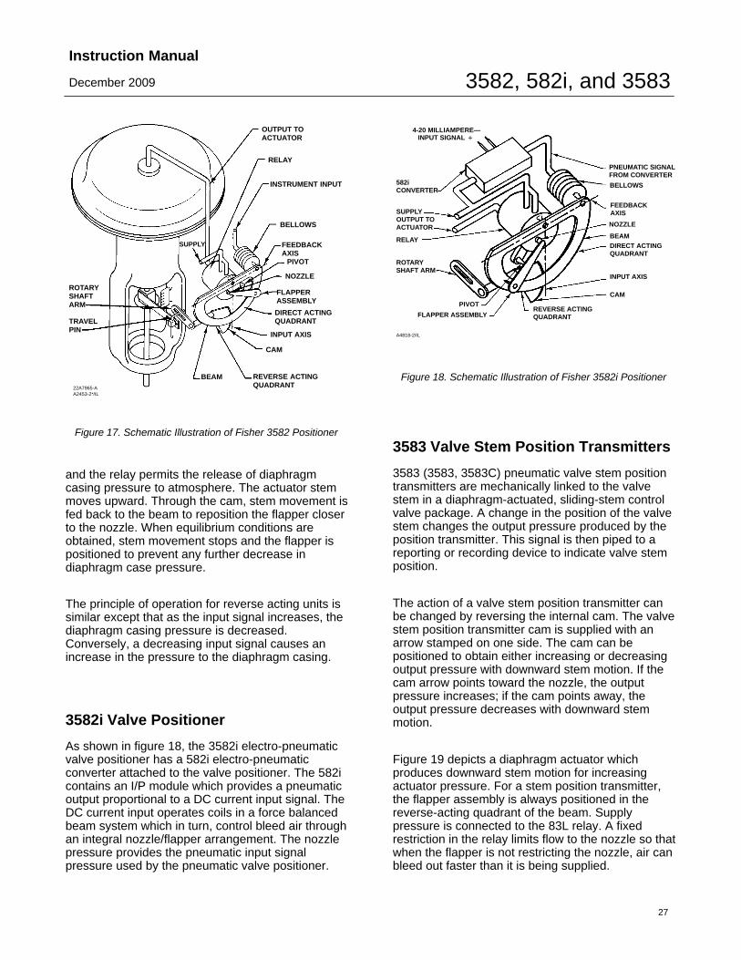
3582 Valve PositionersThe 3582 (3582, 3582NS and 3582A, C, D, and Gpneumatic valve positioners) accepts a pneumaticinput signal from a control device. Figure 17 is anoperational schematic for a direct-acting pneumaticvalve positioner.
As shown in figure 17, in a diaphragm-actuated,sliding stem control valve package with a 3582 valvepositioner, supply pressure is connected to the 83Lrelay. A fixed restriction in the relay limits flow to thenozzle so that when the flapper is not restricting thenozzle, air can bleed out faster than it is beingsupplied.
The input signal from the control device is connectedto the bellows. When the input signal increases, thebellows expands and moves the beam. The beampivots about the input axis moving the flapper closerto the nozzle. The nozzle pressure increases and,through relay action, increases the output pressureto the actuator. The increased output pressure to theactuator causes the actuator stem to movedownward. Stem movement is fed back to the beamby means of a cam. As the cam rotates, the beampivots about the feedback axis to move the flapperslightly away from the nozzle. The nozzle pressuredecreases and reduces the output pressure to theactuator. Stem movement continues, backing theflapper away from the nozzle, until equilibrium isreached.
When the input signal decreases, the bellowscontracts (aided by an internal range spring) and thebeam pivots about the input axis to move the flapperaway from the nozzle. Nozzle pressure decreases
3582, 582i, and 3583Instruction Manual
December 2009
27
22A7965-AA2453-2*/IL
OUTPUT TOACTUATOR
RELAY
INSTRUMENT INPUT
BELLOWS
SUPPLY FEEDBACKAXIS
PIVOT
NOZZLE
FLAPPERASSEMBLY
DIRECT ACTINGQUADRANT
INPUT AXIS
CAM
REVERSE ACTINGQUADRANT
BEAM
TRAVELPIN
ROTARYSHAFTARM
Figure 17. Schematic Illustration of Fisher 3582 Positioner
and the relay permits the release of diaphragmcasing pressure to atmosphere. The actuator stemmoves upward. Through the cam, stem movement isfed back to the beam to reposition the flapper closerto the nozzle. When equilibrium conditions areobtained, stem movement stops and the flapper ispositioned to prevent any further decrease indiaphragm case pressure.
The principle of operation for reverse acting units issimilar except that as the input signal increases, thediaphragm casing pressure is decreased.Conversely, a decreasing input signal causes anincrease in the pressure to the diaphragm casing.
3582i Valve Positioner
As shown in figure 18, the 3582i electro-pneumaticvalve positioner has a 582i electro-pneumaticconverter attached to the valve positioner. The 582icontains an I/P module which provides a pneumaticoutput proportional to a DC current input signal. TheDC current input operates coils in a force balancedbeam system which in turn, control bleed air throughan integral nozzle/flapper arrangement. The nozzlepressure provides the pneumatic input signalpressure used by the pneumatic valve positioner.
A4818-2/IL
582iCONVERTER
PIVOTCAM
INPUT AXIS
BEAM
BELLOWS
FEEDBACKAXIS
DIRECT ACTINGQUADRANT
PNEUMATIC SIGNALFROM CONVERTER
NOZZLE
SUPPLYOUTPUT TOACTUATOR
ROTARYSHAFT ARM
RELAY
FLAPPER ASSEMBLYREVERSE ACTINGQUADRANT
4-20 MILLIAMPERE—INPUT SIGNAL �
Figure 18. Schematic Illustration of Fisher 3582i Positioner
3583 Valve Stem Position Transmitters
3583 (3583, 3583C) pneumatic valve stem positiontransmitters are mechanically linked to the valvestem in a diaphragm-actuated, sliding-stem controlvalve package. A change in the position of the valvestem changes the output pressure produced by theposition transmitter. This signal is then piped to areporting or recording device to indicate valve stemposition.
The action of a valve stem position transmitter canbe changed by reversing the internal cam. The valvestem position transmitter cam is supplied with anarrow stamped on one side. The cam can bepositioned to obtain either increasing or decreasingoutput pressure with downward stem motion. If thecam arrow points toward the nozzle, the outputpressure increases; if the cam points away, theoutput pressure decreases with downward stemmotion.
Figure 19 depicts a diaphragm actuator whichproduces downward stem motion for increasingactuator pressure. For a stem position transmitter,the flapper assembly is always positioned in thereverse-acting quadrant of the beam. Supplypressure is connected to the 83L relay. A fixedrestriction in the relay limits flow to the nozzle so thatwhen the flapper is not restricting the nozzle, air canbleed out faster than it is being supplied.
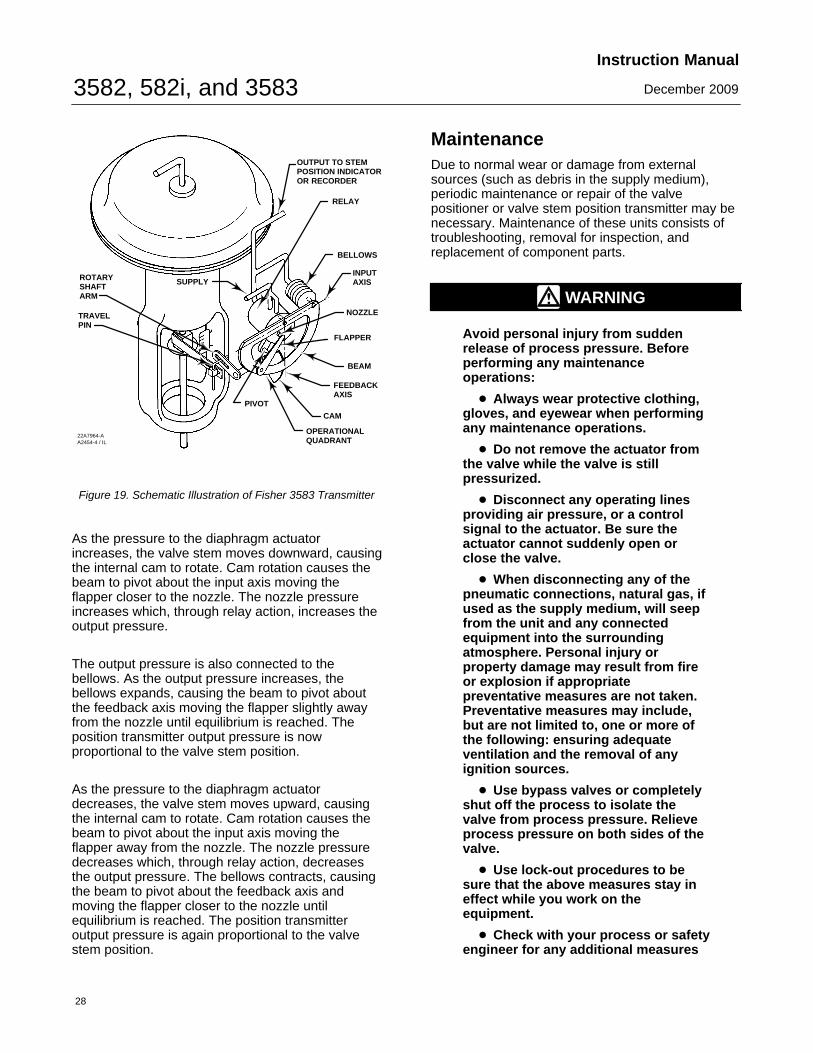
3582, 582i, and 3583Instruction Manual
December 2009
28
OUTPUT TO STEMPOSITION INDICATOROR RECORDER
RELAY
BELLOWS
INPUTAXIS
NOZZLE
FLAPPER
BEAM
FEEDBACKAXIS
CAM
OPERATIONALQUADRANT
ROTARYSHAFTARM
TRAVEL PIN
22A7964-AA2454-4 / IL
SUPPLY
PIVOT
Figure 19. Schematic Illustration of Fisher 3583 Transmitter
As the pressure to the diaphragm actuatorincreases, the valve stem moves downward, causingthe internal cam to rotate. Cam rotation causes thebeam to pivot about the input axis moving theflapper closer to the nozzle. The nozzle pressureincreases which, through relay action, increases theoutput pressure.
The output pressure is also connected to thebellows. As the output pressure increases, thebellows expands, causing the beam to pivot aboutthe feedback axis moving the flapper slightly awayfrom the nozzle until equilibrium is reached. Theposition transmitter output pressure is nowproportional to the valve stem position.
As the pressure to the diaphragm actuatordecreases, the valve stem moves upward, causingthe internal cam to rotate. Cam rotation causes thebeam to pivot about the input axis moving theflapper away from the nozzle. The nozzle pressuredecreases which, through relay action, decreasesthe output pressure. The bellows contracts, causingthe beam to pivot about the feedback axis andmoving the flapper closer to the nozzle untilequilibrium is reached. The position transmitteroutput pressure is again proportional to the valvestem position.
MaintenanceDue to normal wear or damage from externalsources (such as debris in the supply medium),periodic maintenance or repair of the valvepositioner or valve stem position transmitter may benecessary. Maintenance of these units consists oftroubleshooting, removal for inspection, andreplacement of component parts.
WARNING
Avoid personal injury from suddenrelease of process pressure. Beforeperforming any maintenanceoperations:
� Always wear protective clothing,gloves, and eyewear when performingany maintenance operations.
� Do not remove the actuator fromthe valve while the valve is stillpressurized.
� Disconnect any operating linesproviding air pressure, or a controlsignal to the actuator. Be sure theactuator cannot suddenly open orclose the valve.
� When disconnecting any of thepneumatic connections, natural gas, ifused as the supply medium, will seepfrom the unit and any connectedequipment into the surroundingatmosphere. Personal injury orproperty damage may result from fireor explosion if appropriatepreventative measures are not taken.Preventative measures may include,but are not limited to, one or more ofthe following: ensuring adequateventilation and the removal of anyignition sources.
� Use bypass valves or completelyshut off the process to isolate thevalve from process pressure. Relieveprocess pressure on both sides of thevalve.
� Use lock-out procedures to besure that the above measures stay ineffect while you work on theequipment.
� Check with your process or safetyengineer for any additional measures

3582, 582i, and 3583Instruction Manual
December 2009
29
that must be taken to protect againstprocess media.
WARNING
3582i does not meet third partyapprovals for use with natural gas asthe supply medium. Use of natural gasas the supply medium can result inpersonal injury or property damagefrom fire or explosion,
WARNING
For explosion proof applications,disconnect power before removing theconverter housing cap in an explosiveatmosphere.
WARNING
When replacing components, use onlycomponents specified by EmersonProcess Management. Substitutionwith other components may result inthe positioner or transmitter no longermeeting safety certificationrequirements and personal injury orproperty damage.
Always use proper componentreplacement techniques. Impropertechniques and poor quality repairscan impair the safety features of thedevice.
In case of operational difficulties, the valve positioneror valve stem position transmitter should first bechecked to see that adjustments have been properlymade. All pressure lines and connections should bechecked for leaks.
The pneumatic relay and gaskets should also beinspected and replaced if necessary.
Instructions are given below for:
� changing the range spring;
� replacing gaskets, nozzle O-rings, and relay;
� adjusting the flapper pivot;
� replacing the 582i converter primary O-ring andfilter;
� replacing the 582i converter cover O-ring;
� removing the 582i converter; and
� reassembling the 582i converter.
Changing the Range SpringUnless otherwise noted, key number locations areshown in figure 20.
The range spring is inside the bellows assembly.Standard range spring data is given in table 11.When an input signal range is split to operate two ormore control valves, normally changing the rangespring is not necessary. The input signal range forthe range spring is stamped on the nameplate.
Perform the following procedure to change the rangespring in a valve positioner or valve stem positiontransmitter.
1. Unhook the extension springs (keys 27, 77) fromthe beam (key 29).
2. Loosen and remove the two screws (key 13), andlock washers (key 12) that hold the bellowsassembly (key 7) in place.
3. Lift out the beam and bellows assembly. Becareful not to lose the small O-ring (key 11).
4. Loosen the machine screw (key 10), and removethe range spring (key 8).
5. Install a new range spring, making sure the smallend of the spring is against the spring seat (key 9).Replace the spring seat and tighten the screw.
6. If the O-ring (key 11) is worn or damaged,replace it with a new one after applying lubricant(key 94). Make sure the O-ring is in place, theninstall the bellows assembly, securing it with twomounting screws and lock washers.
7. Install the beam over the pivots and hook thesprings to the beam.
8. Make any minor adjustments that may benecessary to re-level the beam as outlined in thebeam alignment procedures of the valve positionersor the valve stem position transmitters calibrationsection. After leveling the beam, calibrate the unitaccording to the appropriate calibration instructions.
Replacing GasketsUnless otherwise noted, key numbers used in thisprocedure are shown in figures 24 and 25.
A gasket (key 34C) is located behind the bypasshandle (key 34D) of 3582 valve positioners or the

3582, 582i, and 3583Instruction Manual
December 2009
30
manifold (key 34D) of 3583 valve stem positiontransmitters.
1. Remove the screw (key 34G), and lift out thebypass handle or manifold.
2. Remove the gasket.
3. Apply lubricant (key 94) to both sides of thereplacement gasket when used with the bypassassembly of 3582 valve positioners. Do not applylubricant to the gasket when the bypass assembly isnot used.
4. Set the new gasket in place on the four locatingpins and replace the bypass handle or manifold.
The case gasket (key 104) is located between thecase (key 1 in figure 20) and the bypass block (key34A) in a 3582 valve positioner or a 3583 valve stemposition transmitter or the housing of the 582iconverter (key 1 in figure 26).
5. Remove the two mounting screws (key 105 infigures 24 and 25; key 11 in figure 26) that hold thebypass block or converter housing to the case andremove the unit to expose the case gasket.
6. Install a new gasket and replace the bypass blockor converter housing.
Replacing the Nozzle O-RingUnless otherwise noted, key numbers are shown infigures 21 and 23.
1. Remove the two screws (key 19C) that hold theflapper and follower assembly (keys 19B and 19G)to the adjustment arm (key 19A).
CAUTION
For proper operation, be careful not tobend or twist the flapper or nick thenozzle orifice during reassembly.
2. Carefully remove the flapper and followerassembly for access to the nozzle (key 18 in figure 20).
3. Loosen the locking nut (key 71), and unscrew thenozzle (key 18).
4. Remove the locking sleeve (key 72) from thenozzle adaptor (key 3). The nozzle adaptor isbonded to the positioner case with adhesive (key 96)and should not be removed.
5. Inspect the O-ring (key 73) on the nozzle adapterand replace the O-ring, if necessary. If replacing theO-ring, apply lubricant (key 94) to the O-ring beforeinstalling it on the nozzle adapter.
6. Reinstall the nozzle onto the nozzle adapter,leaving the locking nut loose.
7. Replace the flapper and follower assembly. Makesure the letter ‘‘T’’ on the flapper is visible from thefront of the positioner or transmitter.
8. Perform the beam alignment and calibrationprocedures in the Calibration of Valve Positioner orValve Stem Position Transmitter section.
Replacing the Relay
Note
The relay is not field repairable. If therelay is defective, replace the relay.
Use the following procedure to replace the relayassembly. Refer to figure 20 for key numberlocations, unless otherwise noted.
1. For valve positioners using a bypass, directaction, and a full-range input signal, place thepositioner in bypass operation by moving the bypasshandle to BYPASS. Then, shut off the supplypressure. For all other valve positioners and valvestem position transmitters, isolate the control valvefrom the system and shut off all pressure lines.
Note
A difference between input and valvepositioner output pressure couldcause a transient bump in thecontrolled system when the bypasshandle is moved to BYPASS.
2. Remove the 83L relay (key 32) from the back ofthe case by loosening the two mounting screws (key10, figure 22).
3. Reinstall the new relay assembly on the case,making sure the O-rings (keys 13 and 15, figure 22)are in place. Secure with the two mounting screws(key 10, figure 22).
4. Resume operation by moving the bypass handleto the POSITIONER position or by connecting thevalve positioner or valve stem position transmitterand control valve to the system.
Adjusting the Flapper PivotKey numbers used in this procedure are shown infigure 23.
3582, 582i, and 3583Instruction Manual
December 2009
31
1. Loosen the two screws (key 19C).
2. Tighten the pivot pin (key 19L) by compressingthe upturned ears of the arm support (key 19K).Tighten the screws (key 19C) and make sure theflapper (key 19B) does not rub on the supports.
3. The flapper should be snug, but not constrictingto pivot action.
Replacing the 582i Converter PrimaryO-Ring and Filter
Key numbers used in this procedure are shown infigure 26.
1. Locate and remove the nozzle restriction adaptorassembly (key 4).
2. Inspect and replace, if necessary, the O-rings(keys 5 and 6). Apply lubricant (key 15) to the O-ringbefore replacing.
3. Inspect and replace the filter cartridge (key 23).
Replacing the 582i Converter HousingCap O-Ring
Key numbers used in this procedure are shown infigure 26.
1. Unscrew and remove the converter housing cap(key 2). Inspect and replace the O-ring (key 8), ifnecessary. Apply lubricant (key 15) to the O-ringbefore replacing.
Removing the 582i Converter
During the following converter removal procedures,refer to figure 26 for key number locations.
CAUTION
The I/P module should never bedisassembled because the magnetismin the coils will decrease permanently.If troubleshooting or alignmentattempts indicate a faulty I/P module,replace the module or return theconverter to your Emerson ProcessManagement sales office for repair.
Note
To check the operation of the I/Pmodule, remove the pipe plug (key 12),and connect a pressure gauge.Provide a 1.4 bar (20 psig) supplypressure to the converter. With a 4 mAsignal the pressure output should read0.16 to 0.24 bar (2.3 to 3.5 psig). With a20 mA input signal the pressure outputshould read 0.96 to 1.07 bar (14.0 to15.5 psig).
1. Turn off the input signal to the converter. Releaseall supply pressure from the valve positioner.
2. Remove the housing cap (key 2).
3. Note the location of the wires, disconnect the fieldwiring from the terminal block. Disconnect thegrounding wire from the external ground screw (key 10).
4. To remove the I/P module, remove the twoscrews (key 9), and pull the module out of thehousing. Inspect the O-ring (key 6) and replace it, ifnecessary. Apply lubricant (key 15) to the O-ringbefore replacing.
a. To remove the entire 582i converter from the3582i valve positioner, continue with steps 5through 7.
b. To replace the I/P module only, obtain areplacement I/P module listed in the parts list andrefer to the procedures for reassembling the 582iconverter.
5. Disconnect the supply tubing, output tubing, andelectrical conduit from the converter.
6. If necessary, remove the 67CFR regulator byremoving the two screws (key 13). Then, remove theregulator from the converter assembly. Inspect theO-ring (key 3) and replace it if necessary. Applylubricant (key 15) to the O-ring before replacing.
7. Remove the two screws (key 11) holding the 582iconverter to the valve positioner case. Remove theconverter from the valve positioner case (key 1 infigure 20). Inspect the gasket (key 20) and replace itif necessary.
Reassembling the 582i ConverterDuring the following converter reassemblyprocedures, refer to figure 26 for key numberlocations.
1. If the 582i converter was removed from the valvepositioner, install a new gasket (key 20) between the
3582, 582i, and 3583Instruction Manual
December 2009
32
converter housing and the valve positioner case.Attach the converter housing to the valve positionercase with the screws (key 11) and tighten thescrews.
2. If the I/P module was removed from the 582iconverter, reinstall the I/P module in the converterhousing. Secure the I/P module with the two screws(key 9).
3. If other valve positioner components areremoved, refer to the appropriate reassemblyprocedures and assemble the valve positionercompletely.
4. Reconnect the supply tubing, output tubing, andconduit to the valve positioner.
5. Reconnect the wiring to the terminal block. Donot overtighten the terminal screws. Maximumtorque is 0.45 N�m (4 lbf�in.). Reconnect thegrounding wire to the housing ground screw (key 10)and replace the cap (key 2).
Note
To check the operation of the I/Pmodule, remove the pipe plug (key 12),and connect a pressure gauge.Provide a 1.4 bar (20 psig) supplypressure to the converter. With a 4milliampere input signal the pressureoutput should read 0.16 to 0.24 bar (2.3to 3.5 psig). With a 20 milliampereinput signal the pressure outputshould read 0.96 to 1.07 bar (14.0 to15.5 psig).
6. Plug the output connection and apply 2.4 bar (35psig) to the supply pressure connection.
CAUTION
Do not apply a signal greater than 35mA to the I/P module. Higher signalvalues may damage the convertermodule.
7. Apply a 20 milliampere DC current input signal tothe converter.
8. Check for leaks using a soap solution. Check anycomponents which were disassembled ordisconnected.
Parts OrderingA serial number is assigned to each valve positioneror valve stem position transmitter and is stamped onthe nameplate. Always refer to this number whencorresponding with your Emerson ProcessManagement sales office regarding spare parts ortechnical information. When ordering parts, also givethe eleven-digit part number shown in the followingparts list.
WARNING
Use only genuine Fisher replacementparts. Components that are notsupplied by Emerson ProcessManagement should not, under anycircumstances, be used in any Fisherinstrument. Use of components notsupplied by Emerson ProcessManagement may void your warranty,might adversely affect theperformance of the instrument, andcould cause personal injury orproperty damage.
Note
Neither Emerson, Emerson ProcessManagement, nor any of their affiliatedassociates assumes responsibility forthe selection, use, or maintenance ofany product. Responsibility for theselection, use and maintenance of anyproduct remains with the purchaserand end user.
Parts Kits
Description Part Number
Repair kit for positioner/transmitter (not for 3582NS)Kit contains keys 11, 16, 17, 33B, 34C, 73, and 104.This kit also contains keys 18C, 18E, and 18Ffor 3580 and 3581 positionersFor standard temperature applications R3580X00022For high temperature applications R3580X00032
Repair kit w/nozzle and flapper for the 3582 PositionerKit contains keys 11, 16, 17, 18, 19B, 19E,33B, 34C, 73, and 104.For standard temperature applications,not for 3582NS R3582X00012
For high temperature applications,not for 3582NS R3582X00022
For 3582NS, contains EPDM parts R3582X00032

3582, 582i, and 3583Instruction Manual
December 2009
33
Description Part Number
Repair kit for 582i electro-pneumatic converterKit contains keys 3, 5, 6, 8, 20, and 23 R582X000012
Replacement kit for 83L RelayKit contains relay, gaskets and mounting screws (key 32 infigure 20, keys 10, 13, and 15 in figure 22)For 3582 except 3582NS, std. const. R3580XRS012For 3582 except 2825NS,Remote Vent, std. temp. R3580XRR012
For 3582 except 3582NS,hi-temp. const. R3580XRH012
For 3582 except 3582NS,Remote Vent, hi-temp. R3580XRR022
For 3582NS R3580XNS012For 3583, std. const. R3580XRS022For 3583, hi-temp. const. R3580XRH032
Parts List
Positioner/Transmitter Common Parts(figure 20)
Note
Parts in the following list are common to both 3582valve positioners and 3583 position transmitters,unless identified by specific type number.
Note
Part numbers are shown for recommended sparesonly. For part numbers not shown, contact yourEmerson Process Management sales office.
Key Description Part Number
1 Case Assembly, Aluminum and PEEK2* Shaft Assembly, SST/steel
For all except 3582NS and high vibrationFor travel up to 54 mm (2.125 inch) 15A9609X012For travel up to 102 mm (4 inch) 15A9609X022
For 3582NS and high vibrationFor travel up to 54 mm (2.125 inch) 15A9609X102For travel up to 102 mm (4 inch) 15A9609X112
Key Description Part Number
2 Shaft Assembly, SST/steelFor 3582NS and high vibrationFor travel up to 54 mm (2.125 inch)
3 Nozzle Adaptor, SST
4 Cam, SSTCam A (For all types except 3582NS)Cam B(For all except 3582NS, 3583, 3583C)
Cam C(For all except 3582NS, 3583, 3583C)
4 Cam, SST/nitride (for 3582NS and high vibration)Cam A (for all types)Cam B (For all except 3583, 3583C)Cam C (For all except 3583, 3583C)
6 Cam Bolt, 416 SST7* Bellows Assembly
Standard brass 13B8783X012For sour gas 13B8783X022
8 Range Spring, pl steel (see table 11)0.2 to 1.0 bar (3 to 15 psi)0.4 to 2.0 bar (6 to 30 psi)
9 Spring Seat, aluminum10 Machine Screw, pl steel11* O-Ring
Std. const., NitrileAll except 3582NS 1F463606992
Hi-temp. const., Fluorocarbon3582A, 3582C & 3583C 1N5714063823582NS, EPDM Duro 80A 17B4784X012
12 Lockwasher, pl steel (2 req’d)13 Machine Screw, pl steel (2 req’d)18 Nozzle, SST
35823583
19 Flapper Sub-Assembly
Note
Parts 19A through 19L are shown in figure 23.
19A Adjustment Arm, pl steel19B Flapper, SST19C Machine Screw, pl steel (2 req’d)19D Flapper Arm, aluminum19E Machine Screw, pl steel (2 req’d)19F Flapper Spring, SST19G Zero Adjustment Screw, 18-8 SST/PEEK
19H Hex Nut, pl steel19J Lockwasher, pl steel19K Arm Support, SST19L Pivot Pin, 440C SST20 Setting Adjustment Gear,
All except 3582NS, nylon3582NS, 316 SST
*Recommended spare parts

3582, 582i, and 3583Instruction Manual
December 2009
34
41B8558-E/DOC
NOTE:APPLY A GOOD-QUALITY THREAD
LOCKING COMPOUND TO THE THREADOF THE NOZZLE ADAPTOR (KEY 3).
1
1
C
A
A B
C
B
SECTION B‐B
SECTION C‐C
SECTION A‐A
TYPICAL CAM(KEY 4)
Figure 20. Fisher 3582 and 3583 Positioners and Transmitters Assembly Drawing

3582, 582i, and 3583Instruction Manual
December 2009
35
12A7441-C / DOC
Figure 21. Nozzle Sub-Assembly
Key Description Part Number
21 Flapper Assembly Retainer, SST23 Self Tapping Screw, pl steel (2 req’d)25 Nameplate, aluminum26 Self Tapping Screw, steel (2 req’d)27 Extension Spring, SST28 Machine Screw, pl steel (3 req’d)29 Beam Sub-Assembly
For all except 3582NS and high vibration 19B3119X012For 3582NS and high vibration 22B3645X022
30 Bellows Pivot Pin, SST32 83L Relay
See Parts Kits, Replacement Kit for 83L Relay33 Cover Assembly
PlasticFor all types except 3582NS
AluminumFor all types except 3583, 3583CFor 3583 and 3583C
Note
Bypass block assembly (key 34) and partsare listed later in this parts list. Non-bypassblock assembly (also key 34) and parts arelisted following the bypass block assemblyand parts.
Parts 35, 36 and 37 are shown in figures 24and 25.
35 Pipe Plug, pl steelReq’d when gauges or test connections are not used:3 req’d for 3582 positionersPlated carbon steel316 SST
36* Output Gauge, Dual Scale3582, 3582G, 35830−30 psig/0−2 kg/cm2 11B4040X0420−60 psig/0−4 kg/cm2 11B4040X052
36* Output Gauge, Triple Scale3582, 3582G, 35830−30 psig/0−0.2 MPa/0−2 bar 11B4040X0120−60 psig/0−0.4 MPa/0−4 bar 11B4040X022
UNITS STAMPED WITH AN H INDICATE HIGH TEMPERATURE CONSTRUCTION
32B0255-B
Figure 22. 83L Relay
13A1451-E/DOC
ASSEMBLE WITH LETTER TON THIS SURFACE
Figure 23. Flapper Sub-Assembly (Key 19)
Key Description Part Number
37* Supply Gauge, Dual Scale3582, 3582G, 35830−30 psig/0−2 kg/cm2 11B4040X0420−60 psig/0−4 kg/cm2 11B4040X052
37* Supply Gauge, Triple Scale3582, 3582G, 35830−30 psig/0−0.2 MPa/0−2 bar 11B4040X0120−60 psig/0−0.4 MPa/0−4 bar 11B4040X022
38 Extension Spring, SST39 Shipping Stop (not shown)42 Hex Nut, pl steel (2 req’d)
43 Spring Retainer Bracket, SST44 Gear Mounting Plate, aluminum45 Locking Nut, aluminum
*Recommended spare parts

3582, 582i, and 3583Instruction Manual
December 2009
36
21B8560-B/DOC21B8562-B/DOC
3582 3582D AND 3582NSSECTIONAL OF 3582
(WITH BYPASS)
TYPICAL SECTION AA
NOTE:KEY 34B AND 103 NOT SHOWN
Figure 24. Fisher 3582 Block Assembly with Bypass
Key Description Part Number
Note
Parts 46 and 47 are shown in figures 24 and 25.
46* Instrument Gauge, Dual Scale0−30 psig/0−2 kg/cm2
(3−15 psig/0.2−1.0 kg/cm2 ranges) 11B4040X0420−60 psig/0−4 kg/cm2
(6−30 psig/0.4−2.0 kg/cm2 ranges) 11B4040X052
46* Instrument Gauge, Triple Scale0−30 psig/0−0.2 MPa/0−2 bar(3−15 psig/20−100 kPa/0.2−1 bar ranges) 11B4040X012
0−60 psig/0−0.4 MPa/0-4 bar(6−30 psig/40−200 kPa/0.4−2 bar ranges) 11B4040X022
47 Test Connection3582C, 3582D (3 req’d)3583C (2 req’d)3582NS (3 req’d)
71 Locking Nut, aluminum72 Locking Sleeve, aluminum
73* O-Ring (2 req’d)Std. const., NitrileAll except 3582NS 10A0871X012
Hi-temp. const., Fluorocarbon3582A, 3582C & 3583C 14A0592X0123582NS, EPDM 17B4783X012
Key Description Part Number
75 Machine Screw, pl steel76 Beam Pivot Pin, SST77 Extension Spring, SST78 Speed Nut, SST
93 Anti-Seize sealant (not furnished with positioner)94 Lubricant, silicone sealant (not furnished with positioner)
95 Lubricant, All except 3582NS,Lithium grease (not furnished with positioner)
3582NS,Molykote� 33 grease (not furnished with positioner)
96 Adhesive, Loctite� 680� Retaining Compound(not furnished with positioner)
103* O-Ring, nitrile, (not shown) used with integrallymounted 67CFR filter regulator 1E591406992
Note
Parts 104 and 105 shown in figures 24 and 25.
104* Case Gasket,Std. const. 1U907804132Hi-temp. const. 1U9078X00123582NS, EPDM 17B4782X012
105 Machine Screw, SST (2 req’d)108 Shipping tag (not shown)
*Recommended spare parts

3582, 582i, and 3583Instruction Manual
December 2009
37
21B8565-B/DOC 21B8564-B/DOC 21B8567-B/DOC
21B8566-B/DOC21B8563-B/DOC
3582C AND 3582NS
NOTE:PIPE PLUG (KEY 106) ON 3583 AND 3583C ONLY.
3582A 3583C
35833582G
SECTIONAL WITHOUT BYPASS
TYPICAL SECTION AA
Figure 25. Fisher 3582 and 3583 Block Assemblies without Bypass
Key Description Part Number
For Units With Bypass (figure 24)Note
Bypass block assembly (key 34) and partsare listed below. Non-bypass block assembly(also key 34) and parts are listed followingthe bypass block assembly and parts.
34 Block Assembly3582, 3582D3582NS
34A Bypass Block, aluminum34B* Groove-Pin, pl steel (not shown) (4 req’d) 1L94282899234C* Bypass Gasket
3582, 3582D, chloroprene 1V6062041323582NS, EPDM 17B4780X012
34D Bypass Handle, aluminum34E Spring, pl steel34F Washer, polyethylene34G Screw, pl steel34K Spring Seat, SST34L Spring Retainer, pl steel
Key Description Part Number
For Units Without Bypass (figure 25)
34 Non-Bypass Block AssemblyStd. const.3582A, 3582C, 3582G3583, 3582C
Hi-temp. const.3582A, 3582C3583C3582NS
34A Bypass Block, aluminum34C* Gasket
Std. const., chloroprene 1V606204132Hi-temp. const. 1V6062X00123582NS, EPDM 17B4780X012
34D Manifold3582, std. and hi-temp. const.3583, std. and hi-temp. const.
34G Cap Screw, pl steel
106 Pipe Plug, pl steelFor 3583 & 3583C (2 req’d)
*Recommended spare parts

3582, 582i, and 3583Instruction Manual
December 2009
38
31B5995-G/DOC
SECTION A‐AA A
I/P MODULE
67CFRFILTER REGULATOR
NOTE:GAUGES MAY BE REPLACED BY PIPE PLUGS
(KEY 12) OR TIRE VALVES (KEY 7).1
1
1
APPLY LUB/SEALANT
Figure 26. Fisher 582i Converter
Key Description Part Number
582i (figure 26)
−−− I/P Module1 Housing
1/2 NPT conduit connection
2 Cap, aluminum−−− Screw, (not shown)
Used to lock cap3* O-Ring, nitrile, used with integrally-mounted
67CFR filter regulator 1E591406992
4 Nozzle Restriction Assembly,Aluminum/Brass/SST
5 O-Ring, Fluorosilicone6* O-Ring, Nitrile (2 req’d) 1C8538X01627 Tire Valve (not shown)
(2 req’d w/tire valve option) 1N908899012
8* O-Ring, Nitrile 1H8762X00129 Machine Screw, 304 SST (2 req’d)
Key Description Part Number
10 Wire Retaining Screw (2 req’d)11 Machine Screw, SST (2 req’d)12 Pipe Plug, steel (2 req’d w/pipe plug option)
13 Screw, pl steel, used withintegrally-mounted 67CFRfilter/regulator (2 req’d)
14* Supply Gauge, Dual Scale0−30 psig/0−2 kg/cm2 11B4040X0420−60 psig/0−4 kg/cm2 11B4040X052
14* Supply Gauge, Triple Scale0−30 psig/0−0.2 MPa/0−2 bar 11B4040X0120−60 psig/0−0.4 MPa/0−4 bar 11B4040X022
15 Lubricant, Lithium grease (not furnished with positioner)16 Anti-seize sealant (not furnished with positioner)18 Self-Tapping Screw, SST (2 req’d)19 Nameplate, SST,
without 3rd party approvals20* Case Gasket, cork21 Cable Gland, plastic,
I.S. approved22* Output Gauge, Dual Scale
0−30 psig/0−2 kg/cm2 11B4040X0420−60 psig/0−4 kg/cm2 11B4040X052
*Recommended spare parts

3582, 582i, and 3583Instruction Manual
December 2009
39
Key Description Part Number
22* Output Gauge, Triple Scale0−30 psig/0−0.2 MPa/0−2 bar 11B4040X0120−60 psig/0−0.4 MPa/0−4 bar 11B4040X022
23* Filter 11B5996X01224 Vent Assembly25 Pipe Plug (required when a 582i is used
without an integrally-mounted 67CFRfilter/regulator)SteelSST
Mounting Parts
For Mounting 3582, 3582i, or 3583 Only(figure 2)
Note
Contact your Emerson Process Management salesoffice for mounting FS Numbers.
Part numbers are shown for recommended sparesonly. For part numbers not shown, contact yourEmerson Process Management sales office.
Key Description
48 Connector Arm, pl steel513Size 20Size 32
656Sizes 30, 40, & 60
657 or 667w/o side-mtd. h’wheelSizes 30 & 34Sizes 40 thru 100
w/side-mtd. h’wheelSize 34Sizes 40, 50, & 60Size 45 & 46Sizes 70 thru 100
657NS or 667NSSize 40Size 45Size 70Size 80
657-4, 667-4GXSize 225, 750, 1200, (20, 40 mm travel)Size 1200 (60 mm travel)
Key Description
49 Washer, pl steel513Size 206.4 mm (0.25 inch) stem (none req’d)7.9 mm (0.3125 inch) stem (1 req’d)9.5 mm (0.375 inch) stem (1 req’d)
Size 32 (2 req’d)656Sizes 30, 40, & 6012.7 mm (0.5 inch) stem (1 req’d)19.1 mm (0.75 inch) stem (none req’d)
657w/o side-mtd. h’wheelSizes 30, 34, & 40 (2 req’d)Size 45 thru 70, & 100 (2 req’d)Sizes 80 & 87 (2 req’d)
w/side-mtd. h’wheelSize 34 thru 60 (none req’d)Size 70 (2 req’d)up to 76 mm (3 inch) travel78 to 102 mm (3.0625 to 4 inch) travel
Sizes 80 & 87 (2 req’d)Size 100 (2 req’d)
657-4 (2 req’d)w/o side-mtd. h’wheelSize 70
w/side-mtd. h’wheelSize 70Size 87
667w/o side-mtd. h’wheelSizes 30, 34, & 40 (2 req’d)Size 45 thru 70, & 100 (2 req’d)Size 80 (2 req’d)Size 87up to 51 mm (2 inch) travel52 to 76 mm (2.0625 to 3 inch) travel78 to 102 mm (3.0625 to 4 inch) travel
667w/side-mtd. h’wheelSize 34 thru 60 (none req’d)Size 70 (2 req’d)up to 76 mm (3 inch) travel78 to 102 mm (3.0625 to 4 inch) travel
Size 80 & 87 (2 req’d)Size 100 (2 req’d)
657NS or 667NSSize 40 (2 req’d)Size 45 (2 req’d)Size 70 and 80 (none req’d)
667-4 (2 req’d)w/ or w/o side-mtd h’wheelSize 70Size 87
*Recommended spare parts

3582, 582i, and 3583Instruction Manual
December 2009
40
Key Description
50 Spacer, steel513Size 20 (none req’d)Size 32 (2 req’d)
656 (2 req’d)Sizes 30, 40, & 60
657w/o side-mtd. h’wheelSize 30 thru 60 (none req’d)Size 70up to 51 mm (2 inch) travel (2 req’d)52 to 76 mm (2.0625 to 3 inch) travel (none req’d)78 to 102 mm (3.0625 to 4 inch) travel (2 req’d)
Size 80up to 51 mm (2 inch) travel (none req’d)over 51 mm (2 inch) travel (2 req’d)
Size 87 (2 req’d)up to 76 mm (3 inch) travel78 to 102 mm (3.0625 to 4 inch) travel
Size 100 (2 req’d)up to 64 mm (2.5 inch) travel65 to 102 mm (2.5625 to 4 inch) travel
w/side-mtd. h’wheelSizes 34, 50, & 60 (2 req’d)Size 40 (none req’d)Size 45 & 46 (2 req’d)Sizes 70 & 87 (2 req’d)Size 80up to 51 mm (2 inch) travel (none req’d)over 51 mm (2 inch) travel (2 req’d)
Size 100 (2 req’d)up to 64 mm (2.5 inch) travel65 to 102 mm (2.5625 to 4 inch) travel
657-4 (2 req’d)w/o side-mtd. h’wheelSize 70
w/side-mtd. h’wheelSize 70 & 87
667w/o side-mtd. h’wheelSizes 30 thru 60 (none req’d)Size 70up to 51 mm (2 inch) travel (none req’d)52 to 76 mm (2.0625 to 3 inch) travel (2 req’d)78 to 102 mm (3.0625 to 4 inch) travel (2 req’d)
Size 80up to 51 mm (2 inch) travel (none req’d)over 51 mm (2 inch) travel (2 req’d)
Size 87 (2 req’d)up to 76 mm (3 inch) travel78 to 102 mm (3.0625 to 4 inch) travel
Size 100 (2 req’d)up to 64 mm (2.5 inch) travel65 to 102 mm (2.5625 to 4 inch) travel
Key Description
50 Spacer, steel (cont’d)667
w/side-mtd. h’wheelSize 34 (2 req’d)Sizes 40, 50, & 60 (none req’d)Size 45 & 46 (2 req’d)Sizes 70 & 87Size 80up to 51 mm (2 inch) travel (none req’d)over 51 mm (2 inch) travel (2 req’d)
w/side-mtd. h’wheel (cont’d)Size 100up to 64 mm (2.5 inch) travel65 to 102 mm (2.5625 to 4 inch) travel
657NS or 667NSAll except size 80 (3 req’d)Size 80 (none req’d)
667-4w/ or w/o side-mtd h’wheelSizes 70 & 87
52 Pipe Plug, 316 SST54 Elbow, 3/8-inch, brass (specify quantity)55 Connector, 3/8-inch brass (not shown)
(specify quantity)
56 Cap Screw, pl steel (2 req’d)657NS or 667NSSizes 40, 45, & 70
All other types
57 Hex Nut657NS or 667NSSize 80 (none req’d)
All other types and sizes (2 req’d)58 Lockwasher
657NS or 667NSSize 80 (none req’d)
All other types and sizes (2 req’d)59 Pin Lock, SST60 Travel Pin, SST
657NS or 667NSSize 80 15A8823X012
All other types 1U909646332
61 Pin Holder, SST62 Cap Nut, SST
63 Mounting Plate, steelFor integrally mounted 67CFRFor separately mounted 67CFR
64 Cap Screw, pl steel (5 req’d)65 Cap Screw, hex head (2 req’d)
GXSize 225, 750, 1200, (20, 40 mm travel)Size 1200 (60 mm travel)

3582, 582i, and 3583Instruction Manual
December 2009
41
Key Description
70 Cap Screw, pl steel (2 req’d)513Sizes 20 & 32 (2 req’d)
656Sizes 30, 40, & 60 (2 req’d)
657w/o side-mtd. h’wheelSizes 30 thru 60Size 70Up to 51 mm (2 inch) travel52 to 76 mm (2.0625 to 3 inch) travel78 to 102 mm (3.0625 to 4 inch) travel
Size 80up to 51 mm (2 inch) travelover 51 mm (2 inch) travel
657w/o side-mtd. h’wheelSize 87up to 76 mm (3 inch) travel78 to 102 mm (3.0625 to 4 inch) travel
Size 100up to 64 mm (2.5 inch) travel65 to 102 mm (2.5625 to 4 inch) travel
w/side-mtd. h’wheelSizes 34, 50, & 60Size 40Size 45 & 46Sizes 70 & 87Size 80up to 51 mm (2 inch) travelover 51 mm (2 inch) travel
Size 100up to 64 mm (2.5 inch) travel65 to 102 mm (2.5625 to 4 inch) travel
657-4w/o side-mtd. h’wheelSize 70
w/side-mtd. h’wheelSizes 70 & 87
667w/o side-mtd. h’wheelSizes 30 thru 60Size 70Up to 51 mm (2 inch) travel52 to 76 mm (2.0625 to 3 inch) travel78 to 102 mm (3.0625 to 4 inch) travel
Size 80up to 51 mm (2 inch) travelover 51 mm (2 inch) travel
Size 87Up to 76 mm (3 inch) travel78 to 102 mm (3.0625 to 4 inch) travel
Size 100up to 64 mm (2.5 inch) travel65 to 102 mm (2.5625 to 4 inch) travel
Key Description
70 Cap Screw, pl steel (2 req’d) (cont’d)667w/side-mtd. h’wheelSize 34Sizes 40, 50, 60Size 45 & 46Size 70 & 87Size 80up to 51 mm (2 inch) travelover 51 mm (2 inch) travel
Size 100up to 64 mm (2.5 inch) travel65 to 102 mm (2.5625 to 4 inch) travel
657NS or 667NSSizes 40, 45, & 70 (3 req’d)Size 80 (3 req’d)
667-4Sizes 70 & 87
GXSize 225, 750, 1200, (20, 40 mm travel) andSize 1200 (60 mm travel)
For Competitor’s Actuators0.375 to 0.75 inch stem
85 Cap Screw, hex head (4 req’d)GXSize 225, 750, 1200, (20, 40 mm travel)Size 1200 (60 mm travel)
86 Mounting Bracket (657NS and 667NS only)657NSSize 45
667NSSize 45
657NS or 667NSSize 40Size 70Size 80
97 Spacer, steel657 or 667w/ side-mtd. h’wheelSizes 70 & 87up to 51 mm (2 inch) travel (2 req’d)52 to 76 mm (2.0625 to 3 inch) travel (2 req’d)78 to 102 mm (3.0625 to 4 inch) travel (none req’d)
w/ or w/o side-mtd. h’wheelSize 80up to 51 mm (2 inch) travel (2 req’d)over 51 mm (2 inch) travel (none req’d)
All other types and sizes (none req’d)
*Recommended spare parts
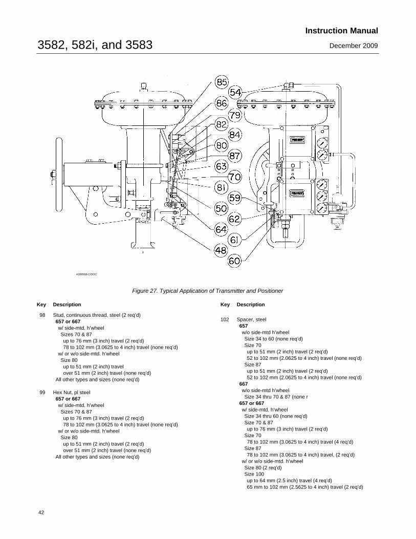
3582, 582i, and 3583Instruction Manual
December 2009
42
41B8568-C/DOC
Figure 27. Typical Application of Transmitter and Positioner
Key Description
98 Stud, continuous thread, steel (2 req’d)657 or 667w/ side-mtd. h’wheelSizes 70 & 87up to 76 mm (3 inch) travel (2 req’d)78 to 102 mm (3.0625 to 4 inch) travel (none req’d)
w/ or w/o side-mtd. h’wheelSize 80up to 51 mm (2 inch) travelover 51 mm (2 inch) travel (none req’d)
All other types and sizes (none req’d)
99 Hex Nut, pl steel657 or 667w/ side-mtd. h’wheelSizes 70 & 87up to 76 mm (3 inch) travel (2 req’d)78 to 102 mm (3.0625 to 4 inch) travel (none req’d)
w/ or w/o side-mtd. h’wheelSize 80up to 51 mm (2 inch) travel (2 req’d)over 51 mm (2 inch) travel (none req’d)
All other types and sizes (none req’d)
Key Description
102 Spacer, steel657w/o side-mtd h’wheelSize 34 to 60 (none req’d)Size 70up to 51 mm (2 inch) travel (2 req’d)52 to 102 mm (2.0625 to 4 inch) travel (none req’d)
Size 87up to 51 mm (2 inch) travel (2 req’d)52 to 102 mm (2.0625 to 4 inch) travel (none req’d)
667w/o side-mtd h’wheelSize 34 thru 70 & 87 (none r
657 or 667w/ side-mtd. h’wheelSize 34 thru 60 (none req’d)Size 70 & 87up to 76 mm (3 inch) travel (2 req’d)
Size 7078 to 102 mm (3.0625 to 4 inch) travel (4 req’d)
Size 8778 to 102 mm (3.0625 to 4 inch) travel, (2 req’d)
w/ or w/o side-mtd. h’wheelSize 80 (2 req’d)Size 100up to 64 mm (2.5 inch) travel (4 req’d)65 mm to 102 mm (2.5625 to 4 inch) travel (2 req’d)
3582, 582i, and 3583Instruction Manual
December 2009
43
Key Description
102 Spacer, steel (cont’td)657w/o side-mtd h’wheelSize 34 to 60 (none req’d)
657-4 or 667-4w/o side-mtd h’wheelSize 70 (none req’d)
w/ side-mtd. h’wheelSize 70 (4 req’d)Size 87 (2 req’d)
GXSize 1200 (60 mm travel)
All other types (none req’d)
For Mounting 3582, 3582i, and 3583 on657 or 667 Actuator withoutSide-Mounted Handwheel
Note
Contact your Emerson Process Management salesoffice for mounting FS Numbers.
Part numbers are shown for recommended sparesonly. For part numbers not shown, contact yourEmerson Process Management sales office.
The following parts (key numbers 48 through 102)are used when mounting both a 3582 positioner anda 3583 transmitter on a 657 or 667 actuator withouta side-mounted handwheel.
48 Connector Arm, pl steel (2 req’d)Sizes 30 & 34Sizes 40 thru 100
49 Washer, pl steel (4 req’d)657Size 70up to 51 mm (2 inch) travel52 mm to 76 mm (2.0625 to 3 inch) travel77 to 102 mm (3.0625 to 4 inch) travel
Size 87667Size 70, all travelsSize 87up to 76 mm (3 inch) travel77 to 102 mm (3.0625 to 4 inch) travel
Key Description Part Number
49 Washer, pl steel (4 req’d) (con’d)657 or 667Sizes 30 thru 40Sizes 45 thru 60Size 80Size 100
up to 64 mm (25 inch) travel65 to 102 mm (2.5625 to 4 inch) travel
50 Spacer, steel657Size 70 & 87up to 76 mm (3 inch) travel (none req’d)77 to 102 mm (3.0625 to 4 inch) travel (4 req’d)
667Size 70 & 87up to 51 mm (2 inch) travel (none req’d)52 to 76 mm (2.0625 to 3 inch) travel (4 req’d)77 to 102 mm (3.0625 to 4 inch) travel (4 req’d)
657Size 70 & 87up to 76 mm (3 inch) travel (none req’d)
657 or 667Sizes 30 thru 60, & 80 (none req’d)Size 100 (4 req’d)up to 64 mm (2.5 inch) travel65 to 102 mm (2.5625 to 4 inch) travel
59 Pin Lock, SST, all sizes (2 req’d)
60 Travel Pin, SST, all sizes (2 req’d) 1U909646332
61 Pin Holder, SST, all sizes (2 req’d)
62 Cap Nut, SST, all sizes (2 req’d)
63 Mounting Plate, steel, all sizes (2 req’d)For integrally mounted 67CFRFor separately mounted 67CFR
64 Cap Screw, pl steel, all sizes (8 req’d)

3582, 582i, and 3583Instruction Manual
December 2009
44
Key Description
65 Cap Screw, pl steel513Size 20 (none req’d)Size 32 (2 req’d)
656 (none req’d)657w/o side-mtd. h’wheelSizes 30, 34, & 40 (2 req’d)Sizes 45 thru 60 (none req’d)Size 70 (2 req’d)up to 51 mm (2 inch) travel52 to 102 mm (2.0625 to 4 inch) travel
w/o side-mtd. h’wheel (cont’d)Size 80up to 51 mm (2 inch) travel (none req’)over 51 mm (2 inch) travel (2 req’d)
Size 87up to 51 mm ( -inch) travel (2 req’d)52 to 102 mm (2.0625 to 4 inch) travel (none req’d)
Size 100 (2 req’d)up to 64 mm (2.5 inch) travel65 to 102 mm (2.5625 to 4 inch) travel
w/side-mtd. h’wheelSizes 34 thru 60 (none required)Size 70up to 76 mm (3 inch) travel (none req’d)78 to 102 mm (3.0625 to 4 inch) travel (2 req’d)
Size 80up to 51 mm (2 inch) travel (none req’d)over 51 mm (2 inch) travel (2 req’d)
Size 87up to 76 mm (3 inch) travel (none req’d)78 to 102 mm (3.0625 to 4 inch) travel (2 req’d)
Size 100 (2 req’d)up to 64 mm (2.5 inch) travel65 to 102 mm (2.5625 to 4 inch) travel
657-4 (2 req’d)w/o side-mtd. h’wheelSize 70
w/ side-mtd. h’wheelSize 70Size 87
667w/o side-mtd. h’wheelSizes 30, 34, & 40 (2 req’d)Sizes 45 thru 70, & 87 (none req’d)Size 80up to 51 mm (2 inch) travel (none req’d)over 51 mm (2 inch) travel (2 req’d)
Size 100 (2 req’d)Up to 64 mm (2.5 inch) travel65 to 102 mm (2.5625 to 4 inch) travel
w/side-mtd. h’wheelSizes 34 thru 60 (none required)Size 70up to 76 mm (3 inch) travel (none req’d)78 to 102 mm (3.0625 to 4 inch) travel (2 req’d)
Key Description
65 Cap Screw, pl steel (cont’d)667w/side-mtd. h’wheelSize 80up to 51 mm (2 inch) travel (none req’d)over 51 mm (2 inch) travel (2 req’d)
Size 87up to 76 mm (3 inch) travel (none req’d)78 to 102 mm (3.0625 to 4 inch) travel(2 req’d)
Size 100 (2 req’d)up to 64 mm (2.5 inch) travel65 to 102 mm (2.5625 to 4 inch) travel
657NS or 667NSSize 40, 45, 70, & 80 (none req’d)
667-4w/o side-mtd. h’wheelSize 70 & 87 (none req’d)
667-4 (cont’d)w/ side-mtd. h’wheelSize 70 (2 req’d)Size 87 (2 req’d)
70 Cap Screw, pl steel (4 req’d)657Size 70 & 87Up to 76 mm (3 inch) travel78 to 102 mm (3.0625 to 4 inch) travel
667Size 70 & 87Up to 51 mm (2 inch) travel52 to 76 mm (2.0625 to 3 inch) travel77 to 102 mm (3.0625 to 4 inch) travel
657 or 667Sizes 30 thru 60, & 80Size 100up to 64 mm (25 inch) travel65 to 102 mm (2.5625 to 4 inch) travel
71 Stud, continuous thread, steel (not shown) (2 req’d)657Size 70Size 87Up to 51 mm (2 inch) travel52 to 102 mm (2.0625 to 4 inch) travel
667Size 70Up to 76 mm (3 inch) travel77 to 102 mm (3.0625 to 4 inch) travel
Size 87Up to 76 mm (3 inch) travel77 to 102 mm (3.0625 to 4 inch) travel
657 or 667Sizes 30, 34, & 40Sizes 45 thru 60Size 80Size 100 (none req’d)
*Recommended spare parts

3582, 582i, and 3583Instruction Manual
December 2009
45
Key Description
72 Hex Nut, pl steel (not shown) (4 req’d)657 or 667Sizes 30, 34, & 40Sizes 45 thru 60Size 70Size 80 & 87Size 100 (none req’d)
102 Spacer657Size 70Up to 51 mm (2 inch) travel (4 req’d)52 to 102 mm (2.0625 to 4 inch) travel (none req’d)
Size 87Up to 51 mm (2 inch) travel52 to 102 mm (2.0625 to 4 inch) travel (none req’d)
Size 70Up to 51 mm (2 inch) travel (4 req’d)
667Size 70Up to 76 mm (3 inch) travel (none req’d)77 to 102 mm (3.0625 to 4 inch) travel (4 req’d)
Size 87Up to 76 mm (3 inch) travel (none req’d)77 to 102 mm (3.0625 to 4 inch) travel (4 req’d)
657 or 667Sizes 30 thru 60 (none req’d)Size 80 (4 req’d)Size 100up to 64 mm (2.5 inch) travel (8 req’d)65 to 102 mm (2.5625 to 4 inch) travel (4 req’d)
For Mounting 3582, 3582i, and 3583 on657 or 667 Actuator with Side-MountedHandwheel
Note
Part numbers are shown for recommended sparesonly. For part numbers not shown, contact yourEmerson Process Management sales office.
The following parts (key numbers 48 through 87)are used when mounting both a 3582 positioner anda 3583 transmitter on a 657 or 667 Size 45 actuatorwith side-mounted handwheel.
48 Connector Arm, pl steel50 Spacer, steel (2 req’d)54 Elbow, 3/8-inch, brass55 Connector, 3/8-inch brass (not shown)59 Pin Lock, SST (2 req’d)
60 Travel Pin, SST (2 req’d) 10A2167X012
61 Pin Holder, SST (2 req’d)
Key Description
62 Cap Nut, SST (2 req’d)63 Mounting Plate, steel (2 req’d)
For integrally mounted 67CFRFor separately mounted 67CFR
64 Cap Screw, pl steel (8 req’d)70 Cap Screw, pl steel (2 req’d)79 Mounting Plate, steel80 Hex Nut, pl steel, for 667 only (2 req’d)81 Lockwasher, pl steel
657 (2 req’d)667 (4 req’d)
82 Machine Screw, pl steel (2 req’d)83 Elastic Stop Nut, pl steel (not shown) (2 req’d)84 Connecting Linkage, pl steel85 Cap Screw, pl steel, for 667 only (5 req’d)86 Spacer, pl steel for 667 only (5 req’d)87 Cap Screw, pl steel for 667 only (2 req’d)
Diagnostic Connections (figure 8)
FlowScanner� valve diagnostics system hook-up.
Includes connector body and body protector. Ifordered for units with gauges, a stem is alsoincluded.
Note
Part numbers are shown for recommended sparesonly. For part numbers not shown, contact yourEmerson Process Management sales office.
For 3582 pneumatic valve positionersFor units w/gaugesSST fittingsbrass fittings
For units w/o gaugesSST fittingsbrass fittings
For 3582i electro-pneumatic valve positionersFor units w/gaugesSST fittingsbrass fittings
For units w/o gaugesSST fittingsbrass fittings

3582, 582i, and 3583Instruction Manual
December 2009
46
Loop Schematics/NameplatesThis section includes loop schematics required for wiring of intrinsically safe installations. It also contains theapprovals nameplates. If you have any questions, contact your Emerson Process Management sales office.
GE28591 Rev A
Figure 28. CSA Loop Schematic for Fisher 582i Converter
Figure 29. CSA / FM Approvals Nameplate for Fisher 582i Converter
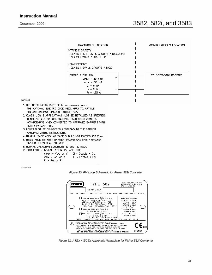
3582, 582i, and 3583Instruction Manual
December 2009
47
GE28590 Rev A
Figure 30. FM Loop Schematic for Fisher 582i Converter
Figure 31. ATEX / IECEx Approvals Nameplate for Fisher 582i Converter
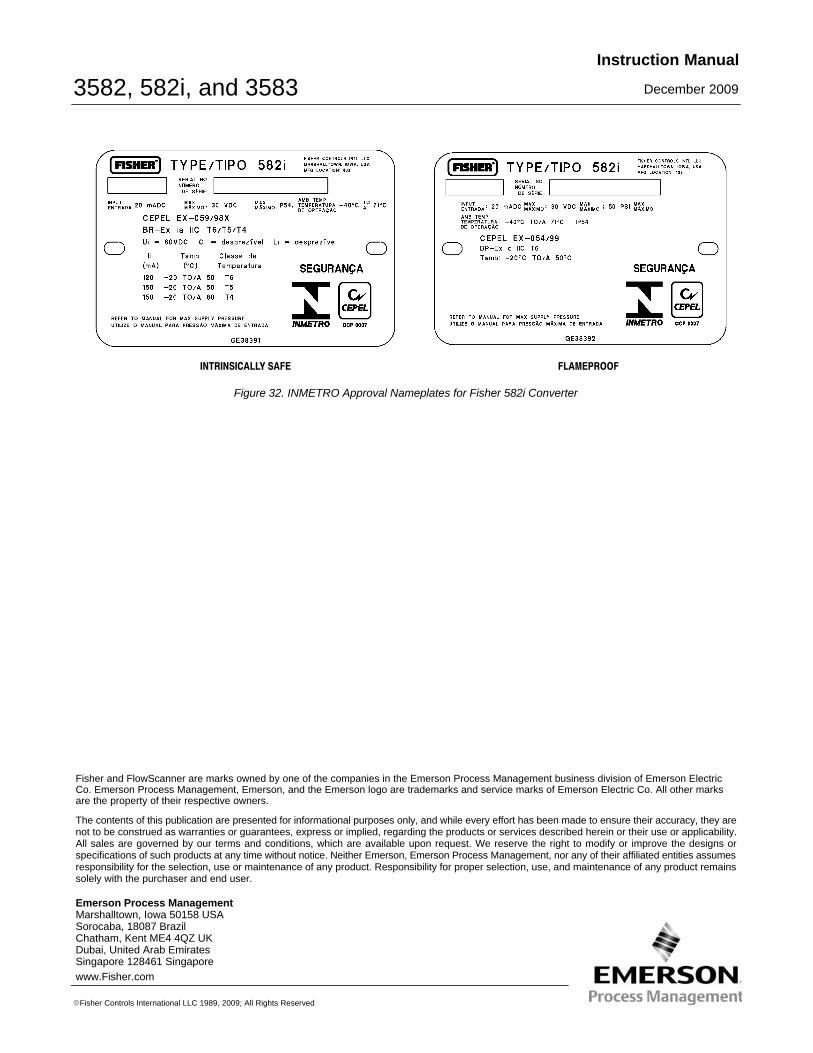
3582, 582i, and 3583Instruction Manual
December 2009
48
INTRINSICALLY SAFE FLAMEPROOF
Figure 32. INMETRO Approval Nameplates for Fisher 582i Converter
Emerson Process Management Marshalltown, Iowa 50158 USASorocaba, 18087 BrazilChatham, Kent ME4 4QZ UKDubai, United Arab EmiratesSingapore 128461 Singaporewww.Fisher.com
The contents of this publication are presented for informational purposes only, and while every effort has been made to ensure their accuracy, they arenot to be construed as warranties or guarantees, express or implied, regarding the products or services described herein or their use or applicability.All sales are governed by our terms and conditions, which are available upon request. We reserve the right to modify or improve the designs orspecifications of such products at any time without notice. Neither Emerson, Emerson Process Management, nor any of their affiliated entities assumesresponsibility for the selection, use or maintenance of any product. Responsibility for proper selection, use, and maintenance of any product remainssolely with the purchaser and end user.
�Fisher Controls International LLC 1989, 2009; All Rights Reserved
Fisher and FlowScanner are marks owned by one of the companies in the Emerson Process Management business division of Emerson ElectricCo. Emerson Process Management, Emerson, and the Emerson logo are trademarks and service marks of Emerson Electric Co. All other marksare the property of their respective owners.


