
SERVICE MANUAL
ML21956/MI91.001716FEB05
Dual Cylinder "Rail" Room Extension (With Synchronizing Cylinder)Dual Cylinder "Vertical Arm" Room Extension
FEATURING:
HWH CORPORATION(On I-80, Exit 267 South)
2096 Moscow Road | Moscow, Iowa 52760Ph: 800/321-3494 (or) 563/724-3396 | Fax: 563/724-3408
www.hwh.com
SPACEMAKER ROOM EXTENSION SYSTEMS310 SERIES HYDRAULIC LEVELING SYSTEM
R
(With Synchronizing Cylinder)
FOR MOTORIZED VEHICLES
CORPORATIONWH H
R
CORPORATIONWH H
R
SECTION 1
MI91.101F09MAR00
SECTION2
FIGURES
SECTION
1
TROUBLE
SHOOTING
GUIDE
2 PART FOLDER
HOW TO USE MANUAL
This manual is written in two sections. Section 1 is the Trouble Shooting Guide. Section 2 is the figures. Begin diagnosis ofthe system with Section 1, the Trouble Shooting Guide. The Trouble Shooting Guide is broken into 3 columns, Problem,Solutions and Figures. Under Problems, find the symptom you have encountered. The testing and repair for that problem isin the Solution (center) column. Diagrams for a particular Problem and Solution are in the Figures (right hand) column. Thiscolumn will direct you to the proper figure in Section 2, Figures, for a more detailed view.
Before beginning your repair, it is IMPORTANT to read the CAUTIONS and NOTES AND CHECKS in the first section, TROUBLESHOOTING GUIDE. In many cases this will save time and mistakes when trouble shooting a system.
This Repair Manual is offered as a guide only. It is impossible to anticipate every problem or combination of problems. Forany problems encountered that are not addressed in this manual, contact HWH Corporation for assistance. (800-321-3494)
PROCEED WITH TROUBLE SHOOTING GUIDE
The room should be fully retracted before Trouble Shooting the system. If the room will not retract, use the manual retract pro-cedure on pages MP35.9490.
Make sure all room locks and the manual retract winch are not engaged before trouble shooting the system.
NOTE: This manual will work for systems with single cylinder room extensions also. The only difference is the exclusionof synchronizing cylinder problems.
TROUBLE SHOOTING
MI91.103F25APR11
WARNING!
BLOCK FRAME AND TIRES SECURELY BEFORE CRAWLING UNDER VEHICLE. DO NOT USE THE LEVELINGJACKS OR AIR SUSPENSION TO SUPPORT VEHICLE WHILE UNDER VEHICLE OR CHANGING TIRES. VEHICLEMAY DROP AND OR MOVE FORWARD OR BACKWARD WITHOUT WARNING CAUSING INJURY OR DEATH.
WHEN ROUTING OR REROUTING HYDRAULIC HOSES AND WIRES, BE SURE THEY ARE NOT EXPOSED TO ENGINEEXHAUST OR ANY HIGH TEMPERATURE COMPONENTS OF THE VEHICLE.
NEVER PLACE HAND OR OTHER PARTS OF THE BODY NEAR HYDRAULIC LEAKS. OIL MAY CUT ANDPENETRATE THE SKIN CAUSING INJURY OR DEATH.
SAFETY GLASSES ARE TO BE WORN TO PROTECT EYES FROM DIRT, METAL CHIPS, OIL LEAKS, ETC. FOLLOWALL OTHER SHOP SAFETY PRACTICES.
NOTES AND CHECKSRead and check before proceeding with Trouble Shooting Steps.
NOTE: HWH CORPORATION ASSUMES NO LIABILITYFOR DAMAGES OR INJURIES RESULTING FROM THEINSTALLATION OR REPAIR OF THIS PRODUCT.
3. If the room extension cannot be retracted, see Figurespage MP35.9490 for temporary measures. Make sure themanual retract valves are closed before trouble shooting.
4. Check that the oil reservoir is full with the room and the level-ing system in the fully retracted position.
5. Batteries should read 12.6 volts. Batteries must be in goodcondition with no weak cells. An alternator, converter or batterycharger will not supply enough power for the system to operate
6. Proper ground of all components is critical. See the elec-trical circuit for specific grounds required. Faulty grounds,especially for the solenoid manifold or the pump assembly,may cause component damage and /or improper or erratic
This manual is intended for use by experienced mechanicswith knowledge of hydraulic and automotive electricalsystems. People with little or no experience with HWHRoom Extension systems should contact HWH technicalservice (800-321-3494) before beginning. Special attentionshould be given to all cautions, wiring, and hydraulic dia-
systems:JUMPER WIRES (UP TO 10 GAUGE)PRESSURE GAUGE (3500 PSI MIN.)MULTI-METER12 VOLT TEST LIGHT
PROCEED WITH THE TROUBLESHOOTING STEPS ON THE
FOLLOWING PAGE
grams.
Suggested tools for trouble shooting the HWH room extension
operation.
IMPORTANT : The room extension will not operate unless ajack is extended enough to turn a Jacks Down Warning light on,but the vehicle should NOT be supported by the leveling jackswhen working on the room extension.
1. The leveling system must work correctly or the room ex-tension will not function properly. If the leveling system is notworking correctly, make the necessary repairs before continuing.
2. The following conditions must be met for the room exten-sion to operate. The ignition must be in the "ACC" positionand the park brake must be set. A red Jacks Down Warninglight on the HWH Panel must be on.
If the room will not retract using the manual winch, there maybe a problem with a room cylinder or the sync. cyl. DO NOTuse alternate devices such as a power winch to retract the room. Contact HWH Customer services (1-800-321-3494)for assistance.
Tightening of hose ends: If tightening a new hose end,make the hose end snug (finger tight) on the fitting, thentighten the hose end 1/3 turn (2 FLATS). If tightening anexisting hose end, tighten the hose end to snug plus 1/4turn (1 FLAT).
properly.

TROUBLE SHOOTING
SOLUTION FIGURESPROBLEM
MI91.203725OCT99
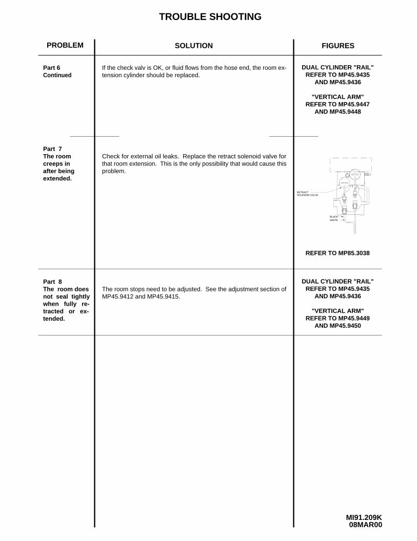
REFER TO MP85.3038
REFER TO MP85.3028
Part 1
Power is not present on Terminal 24.
Power is present on Terminal 24.
Check for +12 at Terminal 24 of the room control switch. Refer toMP85.3038.
Remember, the leveling system must operate properly before testingthe room extension system.
REFER TO MP85.3038
REFER TO MP85.3007
REFER TO MP85.302813
1112
2624
25
1113
2426
12 25The pump willnot run whenthe room ex-tension switchis pushed to-ward EXTENDand / or RE-TRACT.
12
11
13 26
24
25
BROWN
Remember, a red WARNINGlight on the lev-eling systemtouch panelmust be on forthe pump to run.
Check for power on the (BROWN) 6120 wire from the room extension pump control harness.If power is present, the key switch is bad, replace the operator’s panel. If power is not present on the (BROWN) 6120 wire at the op-erator’s panel, refer to MP85.3208. Check the connections and theroom extension power adapter. If the connections are OK and thereis +12 power at the power adapter, the problem is with the (BROWN)6120 wire in the room extension pump control harness.
Check Terminals 25 and 26 ofthe room control switch while pushing the switch to extend and re-tract. If power is not present while pushing the switch, replace theswitch. If power is present, check for +12 power on the (GRAY) 7541wire from the room extension pump control harness at the control box. If power is not present, the (GRAY) 7541 wire is the problem.Refer to MP85.3028.
Power is present on the (GRAY) 7541 wire at the control box. Pin 1, JACK DOWN WARNING SENSOR, of the touch panel cableinput (MP85.3028) should have a ground present if a red Jack DownWarning Light is on. If Pin 1 at the control box has a ground, replacethe control box. If Pin 1, (MP85.3028) at the control box does not have a ground, check Pin 1, (MP85.3007), touch panel cable con-nection. If Pin 1 at the touch panel has a ground, the problem is thetouch panel cable. Check that the wires at both ends are securelyin the connectors. If there is no ground at Pin 1 of the touch panel,replace the touch panel.
CABLETOUCH PANEL1-JACK DOWN
WARNINGSENSOR CONNECTION
(GRAY) 75411-JACKDOWNWARNINGSENSOR
The following is a list of possible problems and solutions which might occur to room extensions. Only qualified techniciansshould install or repair room extension systems. An understanding of the operation of the room extension hydraulic and elec-trical components is required.
The following conditions must be met for the room extension to operate. The ignition must be in the "ACC" position. Thepark brake must be set. A red "Jack Down Warning Light" on the HWH panel must be on. (A jack must be extended app-roximately two inches.) The key switch on the room operator’s panel must be on.
TROUBLE SHOOTING
SOLUTION FIGURESPROBLEM
MI91.208508MAR00
REFER TO MP85.3029
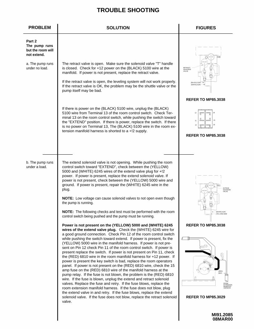
Part 2The pump runsbut the room willnot extend.
NOTE:
NOTE:
a. The pump runsunder no load.
Low voltage can cause solenoid valves to not open even thoughthe pump is running.
The following checks and test must be performed with the roomcontrol switch being pushed and the pump must be running.
b. The pump runsunder a load.
ROOMEXTENSIONMANIFOLDHARNESS
RETRACT
(WHITE) 6245
SOLENOID
(BLACK) 5100
B A
B A
1113
2426
12 25
VALVE
B A
(YELLOW) 5000(WHITE) 6245
SOLENOIDEXTEND
B A
VALVE
REFER TO MP85.3038
REFER TO MP85.3038
REFER TO MP85.3038
13
11
12
26
24
25
- +
The retract valve is open. Make sure the solenoid valve "T" handleis closed. Check for +12 power on the (BLACK) 5100 wire at the manifold. If power is not present, replace the retract valve.
If there is power on the (BLACK) 5100 wire, unplug the (BLACK) 5100 wire from Terminal 13 of the room control switch. Check Ter-minal 13 on the room control switch, while pushing the switch towardthe "EXTEND" position. If there is power, replace the switch. If thereis no power on Terminal 13, The (BLACK) 5100 wire in the room ex-tension manifold harness is shorted to a +!2 supply.
6810(RED)
The extend solenoid valve is not opening. While pushing the roomcontrol switch toward "EXTEND", check between the (YELLOW)5000 and (WHITE) 6245 wires of the extend valve plug for +!2 power. If power is present, replace the extend solenoid valve. If power is not present, check between the (YELLOW) 5000 wire andground. If power is present, repair the (WHITE) 6245 wire in the plug.
Power is not present on the (YELLOW) 5000 and (WHITE) 6245wires of the extend valve plug. Check the (WHITE) 6245 wire fora good ground connection. Check Pin 12 of the room control switchwhile pushing the switch toward extend. If power is present, fix the(YELLOW) 5000 wire in the manifold harness. If power is not pre-sent on Pin 12 check Pin 11 of the room control switch. If power ispresent replace the switch. If power is not present on Pin 11, check the (RED) 6810 wire in the room manifold harness for +12 power. Ifpower is present the key switch is bad, replace the room operators panel. If power is not present on the (RED) 6810 wire, check the 15amp fuse on the (RED) 6810 wire of the manifold harness at the pump relay. If the fuse is not blown, the problem is the (RED) 6810wire. If the fuse is blown, unplug the extend and retract solenoid valves. Replace the fuse and retry. If the fuse blows, replace the room extension manifold harness. If the fuse does not blow, plug the extend valve in and retry. If the fuse blows, replace the extendsolenoid valve. If the fuse does not blow, replace the retract solenoidvalve.
If the retract valve is open, the leveling system will not work properly.If the retract valve is OK, the problem may be the shuttle valve or thepump itself may be bad.
TROUBLE SHOOTING
SOLUTION FIGURESPROBLEM
MI91.209008MAR00
REFER TO MP85.3029
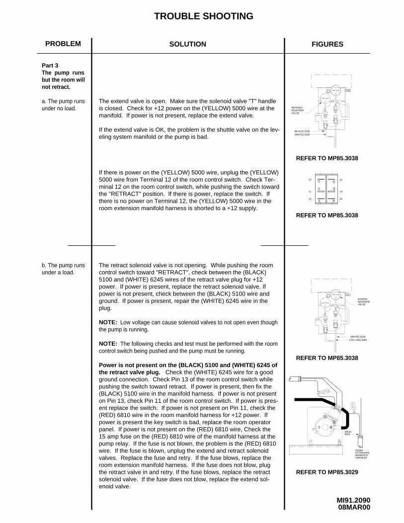
Part 3The pump runsbut the room willnot retract.
NOTE:
NOTE:
a. The pump runsunder no load.
Low voltage can cause solenoid valves to not open even thoughthe pump is running.
The following checks and test must be performed with the roomcontrol switch being pushed and the pump must be running.
b. The pump runsunder a load.
ROOMEXTENSIONMANIFOLDHARNESS
RETRACT
(WHITE) 6245
SOLENOID
(BLACK) 5100
B A
B A
1113
2426
12 25
VALVE
B A
(YELLOW) 5000(WHITE) 6245
SOLENOIDEXTEND
B A
VALVE
REFER TO MP85.3038
REFER TO MP85.3038
REFER TO MP85.3038
13
11
12 25
24
26
- +
The extend valve is open. Make sure the solenoid valve "T" handleis closed. Check for +12 power on the (YELLOW) 5000 wire at themanifold. If power is not present, replace the extend valve.
If there is power on the (YELLOW) 5000 wire, unplug the (YELLOW)5000 wire from Terminal 12 of the room control switch. Check Ter-minal 12 on the room control switch, while pushing the switch towardthe "RETRACT" position. If there is power, replace the switch. Ifthere is no power on Terminal 12, the (YELLOW) 5000 wire in the room extension manifold harness is shorted to a +12 supply.
The retract solenoid valve is not opening. While pushing the roomcontrol switch toward "RETRACT", check between the (BLACK) 5100 and (WHITE) 6245 wires of the retract valve plug for +12 power. If power is present, replace the retract solenoid valve. Ifpower is not present, check between the (BLACK) 5100 wire and ground. If power is present, repair the (WHITE) 6245 wire in the plug.
Power is not present on the (BLACK) 5100 and (WHITE) 6245 ofthe retract valve plug. Check the (WHITE) 6245 wire for a good ground connection. Check Pin 13 of the room control switch whilepushing the switch toward retract. If power is present, then fix the(BLACK) 5100 wire in the manifold harness. If power is not presenton Pin 13, check Pin 11 of the room control switch. If power is pres-ent replace the switch. If power is not present on Pin 11, check the(RED) 6810 wire in the room manifold harness for +12 power. Ifpower is present the key switch is bad, replace the room operatorpanel. If power is not present on the (RED) 6810 wire, Check the 15 amp fuse on the (RED) 6810 wire of the manifold harness at thepump relay. If the fuse is not blown, the problem is the (RED) 6810wire. If the fuse is blown, unplug the extend and retract solenoid valves. Replace the fuse and retry. If the fuse blows, replace the room extension manifold harness. If the fuse does not blow, plugthe retract valve in and retry. If the fuse blows, replace the retract solenoid valve. If the fuse does not blow, replace the extend sol-enoid valve.
6810(RED)
If the extend valve is OK, the problem is the shuttle valve on the lev-eling system manifold or the pump is bad.

TROUBLE SHOOTING
SOLUTION FIGURESPROBLEM
MI91.209F24JUN05
REFER TO MP85.3038
REFER TO MP45.3004
REFER TO MP85.3038
Part 4
Part 5
Part 6
The room moveserratically fromside to side (walk-ing) as it extendsor retracts.
The ends of theroom do not moveat an equal dist-ance from the ve-hicle.
Note :
Check that the pivot bracket is free to pivot. Check that the inner tubes
A : An extend solenoid valve is leaking.B : A room extension cylinder has an internal leak.C : The manifold check valve is leaking.
likely the check valve.
Retract the room completely. Remove the hydraulic line for the capend of the cylinder at the manifold. Hold the hose end in an uprightposition. Press the rocker switch for that room to the "RETRACT"position.
If fluid flows from the manifold fitting, the extend solenoid valve needsto be changed.
the poppet and cap for burrs. The poppet should easily slide in thecap.
NOT lose the spring. Check for cuts on the poppet "O" ring. Checkspect the manifold check valve. There is a spring below the cap. DOIf no fluid flows from either the hose end or the manifold fittings, in-
REFER TO MP65.9418
D : External oil leak.
EXTENDSOLENOID
B A
B A
MANIFOLD
DETAIL B
CAP
POPPET
O-RING
SPRING
VALVE
(YELLOW) 5000(WHITE) 6245
B A
B A
VALVE
EXTENDSOLENOID
CHECKVALVE
MANIFOLDCHECKVALVE
The roomcreeps outafter beingretracted.
are free of paint or undercoating. Make sure the room is not binding onthe top, bottom or sides. Check that the hoses between the rod end ofthe room cylinders and the synchronizing cylinder are the same lengthand diameter. Check that the hoses connected to the cap end of the roomcylinders are the same length and diameter. Check that the room exten-sion mechanisms are not binding. Check that the awning is working prop-erly. If this is all OK contact HWH Customer Service for assistance.
Due to variations such as weight and dimensions from end to end of aroom, it is possible for one end of the room to lead the other when theroom is moving. If the room seals properly top to bottom and end to end, there may not be a problem. Make the same checks as in part 4then call HWH Customer Service for assistance.
The following deals with dual cylinder room extensions.There are four (4) possibilities.
If the room creeps out 1 inch or less the problem is most
If only one side of the room creeps out, replace the room cylinder forthe side that creeps out. If both sides creep out, do the following tests.If the tests are not conclusive, replace the extend solenoid valve for theroom. Check the o-rings at the end of the valve. If the o-rings are dam-
REFER TO MP65.9418
REFER TO MP45.3004
aged, there may be a problem with the manifold.
TROUBLE SHOOTING
SOLUTION FIGURESPROBLEM
MI91.209K08MAR00
REFER TO MP85.3038
Part 7
Part 8The room stops need to be adjusted. See the adjustment section ofMP45.9412 and MP45.9415.
Part 6Continued
Check for external oil leaks. Replace the retract solenoid valve forthat room extension. This is the only possibility that would cause thisproblem.
The room doesnot seal tightlywhen fully re-tracted or ex-tended.
RETRACTSOLENOID VALVE
AB
BLACKWHITE
B A
The roomcreeps inafter beingextended.
"VERTICAL ARM"
If the check valv is OK, or fluid flows from the hose end, the room ex-tension cylinder should be replaced.
AND MP45.9436REFER TO MP45.9435
DUAL CYLINDER "RAIL"
REFER TO MP45.9447AND MP45.9448
AND MP45.9450REFER TO MP45.9449
"VERTICAL ARM"
AND MP45.9436REFER TO MP45.9435
DUAL CYLINDER "RAIL"
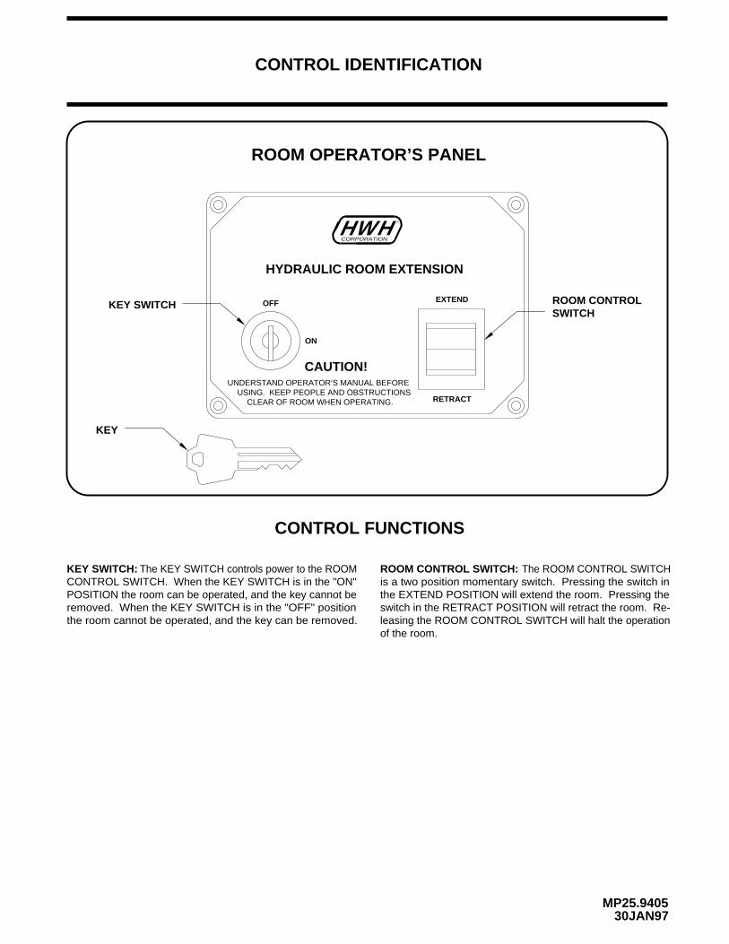
CONTROL FUNCTIONS
CONTROL IDENTIFICATION
MP25.940530JAN97
CORPORATIONH
CAUTION!
CLEAR OF ROOM WHEN OPERATING.
UNDERSTAND OPERATOR’S MANUAL BEFOREUSING. KEEP PEOPLE AND OBSTRUCTIONS
HYDRAULIC ROOM EXTENSION
OFF
ON
RETRACT
HW R
EXTEND ROOM CONTROLSWITCH
KEY SWITCH
The KEY SWITCH controls power to the ROOMCONTROL SWITCH. When the KEY SWITCH is in the "ON"POSITION the room can be operated, and the key cannot beremoved. When the KEY SWITCH is in the "OFF" positionthe room cannot be operated, and the key can be removed.
The ROOM CONTROL SWITCHis a two position momentary switch. Pressing the switch inthe EXTEND POSITION will extend the room. Pressing theswitch in the RETRACT POSITION will retract the room. Re-leasing the ROOM CONTROL SWITCH will halt the operationof the room.
ROOM OPERATOR’S PANEL
KEY
KEY SWITCH: ROOM CONTROL SWITCH:
MP35.949002FEB12
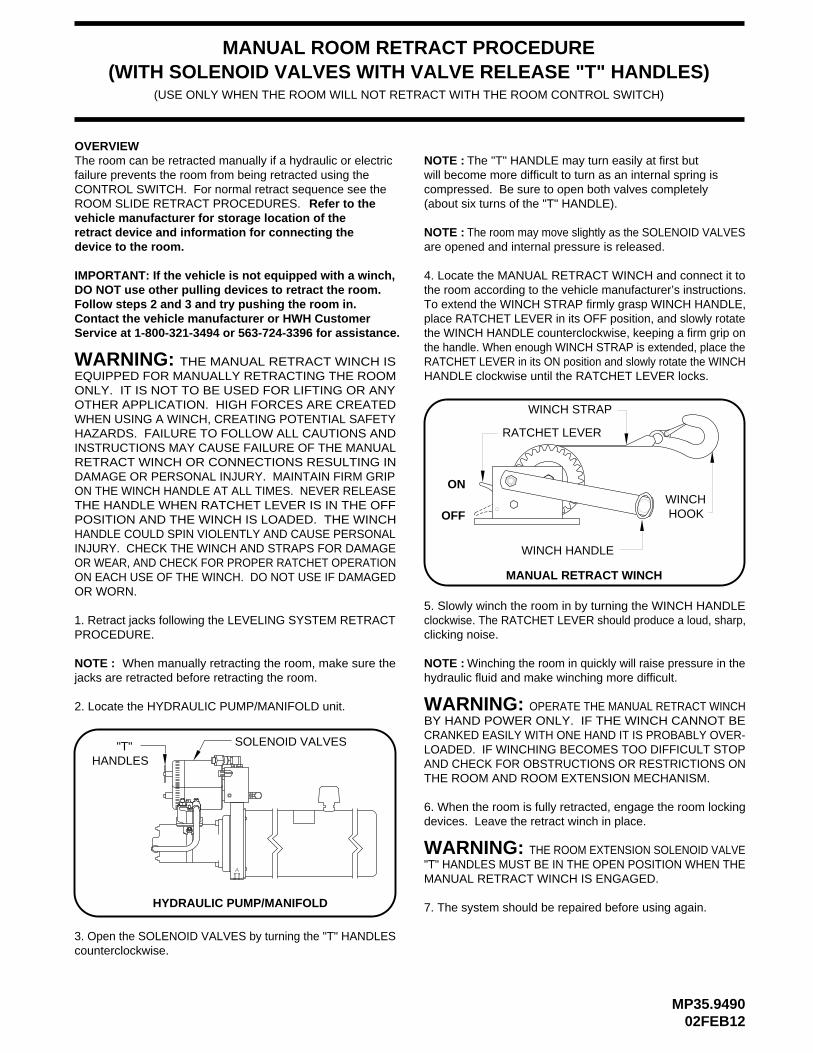
MANUAL ROOM RETRACT PROCEDURE
1. Retract jacks following the LEVELING SYSTEM RETRACTPROCEDURE.
2. Locate the HYDRAULIC PUMP/MANIFOLD unit.
3. Open the SOLENOID VALVES by turning the "T" HANDLEScounterclockwise.
will become more difficult to turn as an internal spring is compressed. Be sure to open both valves completely (about six turns of the "T" HANDLE).
are opened and internal pressure is released.
SOLENOID VALVES"T"HANDLES
(USE ONLY WHEN THE ROOM WILL NOT RETRACT WITH THE ROOM CONTROL SWITCH)
WINCH
WINCH STRAP
WINCH HANDLE
RATCHET LEVER
HOOK
MANUAL RETRACT WINCH
4. Locate the MANUAL RETRACT WINCH and connect it tothe room according to the vehicle manufacturer’s instructions.To extend the WINCH STRAP firmly grasp WINCH HANDLE,place RATCHET LEVER in its OFF position, and slowly rotatethe WINCH HANDLE counterclockwise, keeping a firm grip onthe handle. When enough WINCH STRAP is extended, place theRATCHET LEVER in its ON position and slowly rotate the WINCHHANDLE clockwise until the RATCHET LEVER locks.
5. Slowly winch the room in by turning the WINCH HANDLEclockwise. The RATCHET LEVER should produce a loud, sharp,clicking noise.
hydraulic fluid and make winching more difficult.
WARNING:
ON
OFF
HYDRAULIC PUMP/MANIFOLD
NOTE : The room may move slightly as the SOLENOID VALVES
NOTE : NOTE : Winching the room in quickly will raise pressure in the
NOTE : The "T" HANDLE may turn easily at first but
6. When the room is fully retracted, engage the room lockingdevices. Leave the retract winch in place.
WARNING: THE ROOM EXTENSION SOLENOID VALVE"T" HANDLES MUST BE IN THE OPEN POSITION WHEN THEMANUAL RETRACT WINCH IS ENGAGED.
7. The system should be repaired before using again.
WARNING: THE MANUAL RETRACT WINCH ISEQUIPPED FOR MANUALLY RETRACTING THE ROOMONLY. IT IS NOT TO BE USED FOR LIFTING OR ANY
When manually retracting the room, make sure thejacks are retracted before retracting the room.
OTHER APPLICATION. HIGH FORCES ARE CREATEDWHEN USING A WINCH, CREATING POTENTIAL SAFETY HAZARDS. FAILURE TO FOLLOW ALL CAUTIONS ANDINSTRUCTIONS MAY CAUSE FAILURE OF THE MANUALRETRACT WINCH OR CONNECTIONS RESULTING INDAMAGE OR PERSONAL INJURY. MAINTAIN FIRM GRIP ON THE WINCH HANDLE AT ALL TIMES. NEVER RELEASETHE HANDLE WHEN RATCHET LEVER IS IN THE OFFPOSITION AND THE WINCH IS LOADED. THE WINCHHANDLE COULD SPIN VIOLENTLY AND CAUSE PERSONALINJURY. CHECK THE WINCH AND STRAPS FOR DAMAGEOR WEAR, AND CHECK FOR PROPER RATCHET OPERATIONON EACH USE OF THE WINCH. DO NOT USE IF DAMAGED
OPERATE THE MANUAL RETRACT WINCHBY HAND POWER ONLY. IF THE WINCH CANNOT BECRANKED EASILY WITH ONE HAND IT IS PROBABLY OVER-LOADED. IF WINCHING BECOMES TOO DIFFICULT STOPAND CHECK FOR OBSTRUCTIONS OR RESTRICTIONS ONTHE ROOM AND ROOM EXTENSION MECHANISM.
(WITH SOLENOID VALVES WITH VALVE RELEASE "T" HANDLES)
failure prevents the room from being retracted using theCONTROL SWITCH. For normal retract sequence see theROOM SLIDE RETRACT PROCEDURES.vehicle manufacturer for storage location of theretract device and information for connecting thedevice to the room.
IMPORTANT: If the vehicle is not equipped with a winch,DO NOT use other pulling devices to retract the room.Follow steps 2 and 3 and try pushing the room in.Contact the vehicle manufacturer or HWH CustomerService at 1-800-321-3494 or 563-724-3396 for assistance.
The room can be retracted manually if a hydraulic or electricOVERVIEW
Refer to the
OR WORN.

ML16463/MP45.943527NOV01
2. Loosen the extend valve "T" Handle/Valve release nut.
3. Loosen the retract valve "T" Handle/Valve release nut.
NOTE: Do not remove the caps from the new cylinder
12. Remove Hose A from the room extension manifold. Usea cap from the new cylinder to cap the fitting in the manifold.Direct Hose A into the fluid reservoir.
13. Close the extend & retract valve "T" handles/Valve release nuts.
14. Push and hold the room control switch to "EXTEND" untilthe new cylinder is fully extended plus five seconds.
IMPORTANT: DO NOT PULL THE CYLINDER ROD OUT OF THE NEW CYLINDER. INSTALL THE NEW CYLINDERWITH THE ROD RETRACTED AS IT WAS SHIPPED.
NOTE:
CAUTION:DO NOT TRY TO LINE THE ROOM
THE ROD IS EXTENDING.CYLINDER ROD UP WITH THE MOUNTING HOLE WHILE
15. Reattach Hose A to the room extension manifold.
22. Check all hose connections and mounting nuts and boltsfor tightness and leaks.
hose connections until you are ready to reattach the hoses. Save the caps.
11. Attach the hoses to the cylinder. Do not over tighten thehose ends. See MP45.9436 for tightening of hoses.
8. Remove the cylinder cap end mounting plate from the oldcylinder and attach it to the new cylinder.
10. Install the new cylinder in the room extension tube. DONOT install the two cylinder cap end mounting plate nuts andwashers.
The cap end of the cylinder will push the cylinder capend mounting plate off the room extension tube. This is ok.
17. Slide the cylinder rod thru the rod mounting plate holeon the inner sliding tube. Install the nuts and lock washers onthe cylinder cap end mounting plate. Turn the cylinder rod inneradjusting nut into place and install the cylinder rod outer adjusting nut. Make the nut snug only, as a final adjustment will
6. Remove and cap the hoses at the end of the cylinder that is to be replaced.
IMPORTANT: Steps 4 and 5 must be done to protect the
7. Remove the cylinder that is to be replaced from the room extension tube.
9. Install the inner out stop adjusting nut and lock washer completely onto the threaded rod of the new cylinder.
have to be made. Do this for the front and rear cylinders.
ROOM EXTENSION CYLINDER REPLACEMENTDUAL CYLINDER ROOM EXTENSION(WITH SYNCHRONIZING CYLINDER)
READINSTRUCTIONS
PROCEEDINGBEFORETHOROUGHLYSTOP
IMPORTANT: Do not reverse direction of the room untilthe room is fully extended or retracted.
IMPORTANT: The following instructions must be followed or air lock of the synchronizing cylinder and unsynchronized operation of the room cylinders may result causing damage to the room. Please read the instructions before replacing the cylinder. DO NOT reverse direction of the room unless the room is fully extended or retracted.
1. Extend the room fully. There is an access hole on the inner sliding tube to access the cylinder rod mounting nuts. If the room cannot be fully extended the inner sliding tube access hole must be extended far enough to access the cylinder rod mounting nuts.
room from being damaged while bleeding air from and synchronizing the the room cylinders.
5. Remove the cylinder rod outer out stop adjusting nut for both the front and rear room cylinders.
IMPORTANT: BEFORE INSTALLING THE NEW CYLINDER, CLEAN ALL EXCESS OIL FROM THE ROOM EXTENSION TUBE. SWAB THE TUBE THOROUGHLY WITH A MILD SOLVENT AND RAGS. EXCESS OIL LEFT IN THE TUBE MAY LEAK OUT GIVING THE APPEARANCE OF A LEAKY CYLINDER OR HOSE CONNECTION.
16. Push and hold the room control switch to "RETRACT" until both cylinders are fully retracted, plus 5 seconds. Extend and retract the cylinders at least twice or until they are running fully synchronized. DO NOT reconnect the cylinders until they are running fully synchronized.
18. Push the room control switch to retract and hold until the room is fully retracted plus 5 seconds. Watch for excessive racking of the room. Some racking can occur do to air in the system. If the room starts to bind up, release the room control switch immediately. If the room does not bind up, proceed to Step 20. If the room is bound up, go to Step 19.
19. If the room is bound up, repeat Steps 2, 3, 4 and 5. Manually push the room out to its full extension. Now repeat Steps 13, 16, 17 and 18. If the room will still not run properly, contact HWH CORPORATION Customer Service at (800)321-3494 or at (563)724-3396.
21. With the room fully extended, check seals for proper compression. If the seal is not compressed or needs more compression, loosen the cylinder rod outer adjusting nut and tighten the cylinder rod inner adjusting nut. If the seal is compressed too much, loosen the cylinder rod inner adjusting nut and tighten the cylinder rod outer adjusting nut.
4. Remove the two nuts and washers from the cylinder cap end mounting plate for both the front and rear room cylinders.
20. Extend the room fully again. Do not reverse direction until the room is fully extended. Repeat retracting and extending the room several times being careful not to reverse directions until the room is fully extended or retracted.
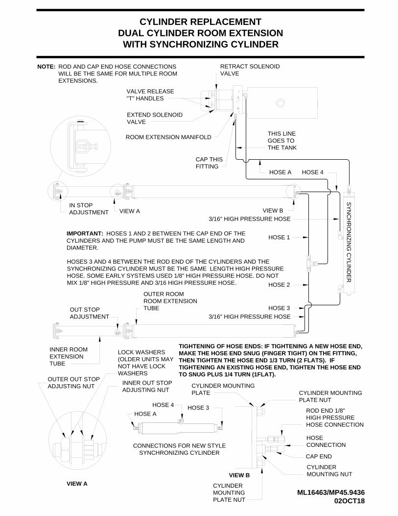
CYLINDER REPLACEMENTDUAL CYLINDER ROOM EXTENSIONWITH SYNCHRONIZING CYLINDER
VIEW A VIEW BIN STOPADJUSTMENT
OUTER ROOMROOM EXTENSIONTUBEOUT STOP
ADJUSTMENT
INNER ROOMEXTENSIONTUBE
HOSE A
THIS LINEGOES TOTHE TANK
CAP THISFITTING
EXTEND SOLENOIDVALVE
RETRACT SOLENOIDVALVE
VALVE RELEASE"T" HANDLES
NOTE: ROD AND CAP END HOSE CONNECTIONSWILL BE THE SAME FOR MULTIPLE ROOMEXTENSIONS.
CYLINDER MOUNTINGPLATE NUT
ROD END 1/8"HIGH PRESSUREHOSE CONNECTION
CAP END
HOSECONNECTION
CYLINDERMOUNTING NUT
CYLINDERMOUNTINGPLATE NUT
CYLINDER MOUNTINGPLATE
VIEW B
OUTER OUT STOPADJUSTING NUT INNER OUT STOP
ADJUSTING NUT
VIEW A
ROOM EXTENSION MANIFOLD
ML16463/MP45.943602OCT18
3/16" HIGH PRESSURE HOSE
SY
NC
HR
ON
IZIN
G C
YLIN
DE
R
LOCK WASHERS(OLDER UNITS MAYNOT HAVE LOCK WASHERS
HOSE 4
3/16" HIGH PRESSURE HOSE
HOSE 1
HOSE 2
HOSE 3
IMPORTANT: HOSES 1 AND 2 BETWEEN THE CAP END OF THECYLINDERS AND THE PUMP MUST BE THE SAME LENGTH AND DIAMETER.
HOSES 3 AND 4 BETWEEN THE ROD END OF THE CYLINDERS AND THESYNCHRONIZING CYLINDER MUST BE THE SAME LENGTH HIGH PRESSUREHOSE. SOME EARLY SYSTEMS USED 1/8" HIGH PRESSURE HOSE. DO NOTMIX 1/8" HIGH PRESSURE AND 3/16 HIGH PRESSURE HOSE.
TIGHTENING AN EXISTING HOSE END, TIGHTEN THE HOSE ENDTHEN TIGHTEN THE HOSE END 1/3 TURN (2 FLATS). IFMAKE THE HOSE END SNUG (FINGER TIGHT) ON THE FITTING, TIGHTENING OF HOSE ENDS: IF TIGHTENING A NEW HOSE END,
TO SNUG PLUS 1/4 TURN (1FLAT).
SYNCHRONIZING CYLINDERCONNECTIONS FOR NEW STYLE
HOSE A
HOSE 4 HOSE 3
ML18750/MP45.944727NOV01
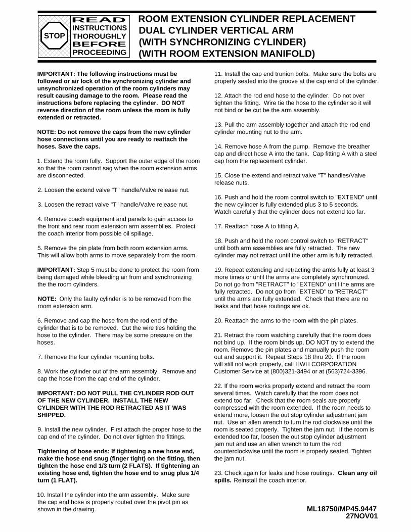
ROOM EXTENSION CYLINDER REPLACEMENTDUAL CYLINDER VERTICAL ARM (WITH SYNCHRONIZING CYLINDER)(WITH ROOM EXTENSION MANIFOLD)
NOTE: Only the faulty cylinder is to be removed from the room extension arm.
7. Remove the four cylinder mounting bolts.
9. Install the new cylinder. First attach the proper hose to thecap end of the cylinder. Do not over tighten the fittings.
11. Install the cap end trunion bolts. Make sure the bolts areproperly seated into the groove at the cap end of the cylinder.
12. Attach the rod end hose to the cylinder. Do not over tighten the fitting. Wire tie the hose to the cylinder so it will not bind or be cut be the arm assembly.
13. Pull the arm assembly together and attach the rod end cylinder mounting nut to the arm.
14. Remove hose A from the pump. Remove the breather cap and direct hose A into the tank. Cap fitting A with a steel cap from the replacement cylinder.
15. Close the extend and retract valve "T" handles/Valve
16. Push and hold the room control switch to "EXTEND" untilthe new cylinder is fully extended plus 3 to 5 seconds. Watch carefully that the cylinder does not extend too far.
17. Reattach hose A to fitting A.
18. Push and hold the room control switch to "RETRACT" until both arm assemblies are fully retracted. The new cylinder may not retract until the other arm is fully retracted.
19. Repeat extending and retracting the arms fully at least 3
20. Reattach the arms to the room with the pin plates.
more times or until the arms are completely synchronized. Do not go from "RETRACT" to "EXTEND" until the arms are fully retracted. Do not go from "EXTEND" to "RETRACT" until the arms are fully extended. Check that there are no leaks and that hose routings are ok.
2. Loosen the extend valve "T" handle/Valve release nut.
3. Loosen the retract valve "T" handle/Valve release nut.
23. Check again for leaks and hose routings. Clean any oilspills. Reinstall the coach interior.
READINSTRUCTIONS
PROCEEDINGBEFORETHOROUGHLYSTOP
existing hose end, tighten the hose end to snug plus 1/4tighten the hose end 1/3 turn (2 FLATS). If tightening anmake the hose end snug (finger tight) on the fitting, thenTightening of hose ends: If tightening a new hose end,
turn (1 FLAT).
IMPORTANT: The following instructions must be followed or air lock of the synchronizing cylinder and unsynchronized operation of the room cylinders may result causing damage to the room. Please read the instructions before replacing the cylinder. DO NOT reverse direction of the room unless the room is fully extended or retracted.
NOTE: Do not remove the caps from the new cylinder hose connections until you are ready to reattach the hoses. Save the caps.
1. Extend the room fully. Support the outer edge of the room so that the room cannot sag when the room extension arms are disconnected.
4. Remove coach equipment and panels to gain access to the front and rear room extension arm assemblies. Protect the coach interior from possible oil spillage.
5. Remove the pin plate from both room extension arms. This will allow both arms to move separately from the room.
IMPORTANT: Step 5 must be done to protect the room from being damaged while bleeding air from and synchronizing the the room cylinders.
6. Remove and cap the hose from the rod end of the cylinder that is to be removed. Cut the wire ties holding the hose to the cylinder. There may be some pressure on the hoses.
8. Work the cylinder out of the arm assembly. Remove and cap the hose from the cap end of the cylinder.
IMPORTANT: DO NOT PULL THE CYLINDER ROD OUT OF THE NEW CYLINDER. INSTALL THE NEW CYLINDER WITH THE ROD RETRACTED AS IT WAS SHIPPED.
10. Install the cylinder into the arm assembly. Make sure the cap end hose is properly routed over the pivot pin as shown in the drawing.
21. Retract the room watching carefully that the room does not bind up. If the room binds up, DO NOT try to extend the room. Remove the pin plates and manually push the room out and support it. Repeat Steps 18 thru 20. If the room will still not work properly, call HWH CORPORATION Customer Service at (800)321-3494 or at (563)724-3396.
22. If the room works properly extend and retract the room several times. Watch carefully that the room does not extend too far. Check that the room seals are properly compressed with the room extended. If the room needs to extend more, loosen the out stop cylinder adjustment jam nut. Use an allen wrench to turn the rod clockwise until the room is seated properly. Tighten the jam nut. If the room is extended too far, loosen the out stop cylinder adjustment jam nut and use an allen wrench to turn the rod counterclockwise until the room is properly seated. Tighten the jam nut.
release nuts.

ML18750/MP45.944802OCT18
ROD END
SYNCHRONIZING CYLINDER
TO SECOND ROOMEXTENSION VERTICAL
ARM ASSEMBLY
GROOVEFOR TRUNIONBOLT
CAP END CYLINDERMOUNTING NUT(NON-THREADED) ROD
REPLACEMENTCYLINDER
ROD END CYLINDERMOUNTING NUT(THREADED)
OUT STOP CYLINDERADJUSTMENT JAM NUT
CYLINDERMOUNTINGBOLT (2)
CAPEND PIVOT
PIN
CYLINDER MOUNTING BOLT (2)CAP END HOSE
PINPLATE
CAPEND
ROD END
IMPORTANT: HOSES 1 AND 2 BETWEEN THE CAP END OF THE CYLINDERS AND THE PUMP MUST BE THESAME LENGTH AND DIAMETER.
HOSES 3 AND 4 BETWEEN THE ROD END OF THE CYLINDERS AND THE SYNCHRONIZING CYLINDER MUST BE THE SAME LENGTH OF 3/16" HIGH PRESSURE HOSE.
NOTE: NEW TRUNION BOLTS,MOUNTING NUTS AND JAMNUTS ARE SUPPLIED WITHTHE REPLACEMENTCYLINDER.
3/16" HIGH PRESSURE HOSEROD END OF CYLINDER
VALVE RELEASE"T" HANDLE
EXTEND SOLENOIDVALVE
FITTING A
HOSE A TO CAP END OFSYNCHRONIZINGCYLINDER
LEVELING SYSTEMMANIFOLD ORFITTINGS NOT SHOWN.
TO CAP END OF ROOMEXTENSION CYLINDER1/8" LINE
CAP END HOSE
CYLINDER REPLACEMENTVERTICAL ARM ROOM EXTENSIONWITH SYNCHRONIZING CYLINDER
RETRACTSOLENOID
VALVE ROOM EXTENSION MANIFOLD
SOME OLDER SYSTEMS USED 1/8" HIGH PRESSUREHOSE. DO NOT MIX 1/8" HIGH PRESSURE AND 3/16" HIGH PRESSURE HOSE.
HOSE 1
HOSE 2
HOSE 3 HOSE 4
CONNECTIONS FOR NEW STYLE
HOSE 4
SYNCHRONIZING CYLINDER
HOSE A
HOSE 3
SYNCHRONIZING CYLINDER
ML18751/MP45.944914SEP99
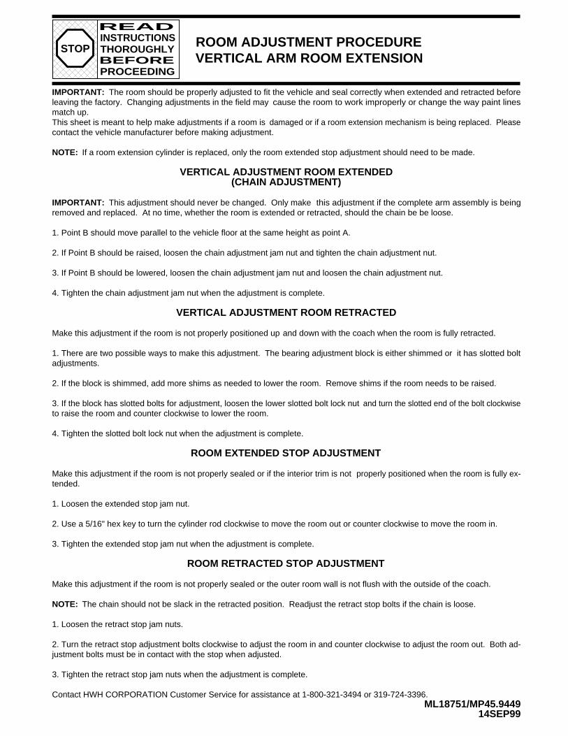
ROOM ADJUSTMENT PROCEDUREVERTICAL ARM ROOM EXTENSION
IMPORTANT: The room should be properly adjusted to fit the vehicle and seal correctly when extended and retracted beforeleaving the factory. Changing adjustments in the field may cause the room to work improperly or change the way paint linesmatch up.This sheet is meant to help make adjustments if a room is damaged or if a room extension mechanism is being replaced. Pleasecontact the vehicle manufacturer before making adjustment.
NOTE: If a room extension cylinder is replaced, only the room extended stop adjustment should need to be made.
VERTICAL ADJUSTMENT ROOM EXTENDED
IMPORTANT: This adjustment should never be changed. Only make this adjustment if the complete arm assembly is beingremoved and replaced.
1. Point B should move parallel to the vehicle floor at the same height as point A.
2. If Point B should be raised, loosen the chain adjustment jam nut and tighten the chain adjustment nut.
3. If Point B should be lowered, loosen the chain adjustment jam nut and loosen the chain adjustment nut.
4. Tighten the chain adjustment jam nut when the adjustment is complete.
VERTICAL ADJUSTMENT ROOM RETRACTED
Make this adjustment if the room is not properly positioned up and down with the coach when the room is fully retracted.
1. There are two possible ways to make this adjustment. The bearing adjustment block is either shimmed or it has slotted boltadjustments.
2. If the block is shimmed, add more shims as needed to lower the room. Remove shims if the room needs to be raised.
3. If the block has slotted bolts for adjustment, loosen the lower slotted bolt lock nut and turn the slotted end of the bolt clockwiseto raise the room and counter clockwise to lower the room.
4. Tighten the slotted bolt lock nut when the adjustment is complete.
ROOM EXTENDED STOP ADJUSTMENT
Make this adjustment if the room is not properly sealed or if the interior trim is not properly positioned when the room is fully ex-tended.
1. Loosen the extended stop jam nut.
2. Use a 5/16" hex key to turn the cylinder rod clockwise to move the room out or counter clockwise to move the room in.
3. Tighten the extended stop jam nut when the adjustment is complete.
ROOM RETRACTED STOP ADJUSTMENT
Make this adjustment if the room is not properly sealed or the outer room wall is not flush with the outside of the coach.
NOTE: The chain should not be slack in the retracted position. Readjust the retract stop bolts if the chain is loose.
1. Loosen the retract stop jam nuts.
2. Turn the retract stop adjustment bolts clockwise to adjust the room in and counter clockwise to adjust the room out. Both ad-justment bolts must be in contact with the stop when adjusted.
3. Tighten the retract stop jam nuts when the adjustment is complete.
Contact HWH CORPORATION Customer Service for assistance at 1-800-321-3494 or 319-724-3396.
(CHAIN ADJUSTMENT)
At no time, whether the room is extended or retracted, should the chain be be loose.
READINSTRUCTIONS
PROCEEDINGBEFORETHOROUGHLYSTOP
ML18751/MP45.945011SEP98
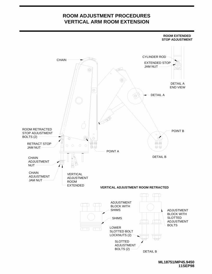
ROOM ADJUSTMENT PROCEDURESVERTICAL ARM ROOM EXTENSION
ROOM EXTENDEDSTOP ADJUSTMENT
CYLINDER ROD
EXTENDED STOPJAM NUT
DETAIL AEND VIEW
CHAIN
ROOM RETRACTEDSTOP ADJUSTMENTBOLTS (2)
RETRACT STOPJAM NUT
CHAINADJUSTMENTNUT
CHAINADJUSTMENTJAM NUT
VERTICALADJUSTMENTROOMEXTENDED
DETAIL A
POINT B
DETAIL B
ADJUSTMENTBLOCK WITHSLOTTEDADJUSTMENTBOLTS
SLOTTEDADJUSTMENTBOLTS (2)
LOWERSLOTTED BOLTLOCKNUTS (2)
SHIMS
ADJUSTMENTBLOCK WITHSHIMS
VERTICAL ADJUSTMENT ROOM RETRACTED
DETAIL B
POINT A

FR
ON
T
RF
RR
LF
LR
SHUTTLE VALVE
"T" HANDLESRELEASEVALVE
LEVELINGSYSTEMMANIFOLD
ROOMEXTENSIONMANIFOLD
HYDRAULIC LINE CONNECTION DIAGRAM310 SERIES LEVELING SYSTEM
DUAL CYLINDERROOM EXTENSION SYSTEM W/SYNCHRONIZING CYLINDER
DUAL CYLINDER ROOM EXTENSION
SY
NC
HR
ON
IZIN
G C
YLIN
DE
R
HYDRAULIC CYLINDER
HYDRAULIC CYLINDER
STEEL TUBE
ROD END CAP END
ROD END CAP END
STEEL TUBE
3/16" HIGHPRESSURE HOSE
LR LF RF RR
EXTENDVALVE
RETRACTVALVE
VALVERELEASE"T" HANDLES
IMPORTANT: THE HOSES BETWEEN THE CAP END AT THE HYDRAULIC CYLINDERSAND THE TEE MUST BE THE SAME LENGTHAND DIAMETER.
3/16" HIGH PRESSURE HOSE
IMPORTANT:
NOTE: SOME SYSTEMSHAVE 1/8" HIGH PRES-SURE HOSE.
ROOM EXTENSION TUBE
HOSE CONNECTION
1/4" HOSECAP END
HOSE HIGH PRESSUREROD END 3/16"
AT REAR OF
CONNECTION
CONNECTION
MP65.300418JAN99
THE 3/16" HIGHPRESSURE HOSES BETWEENTHE STEEL TUBES (ROD END)OF THE HYDRAULIC CYLINDERSAND THE SYNCHRONIZING CYL-INDER MUST BE THE SAME LENGTH AND DIAMETER.
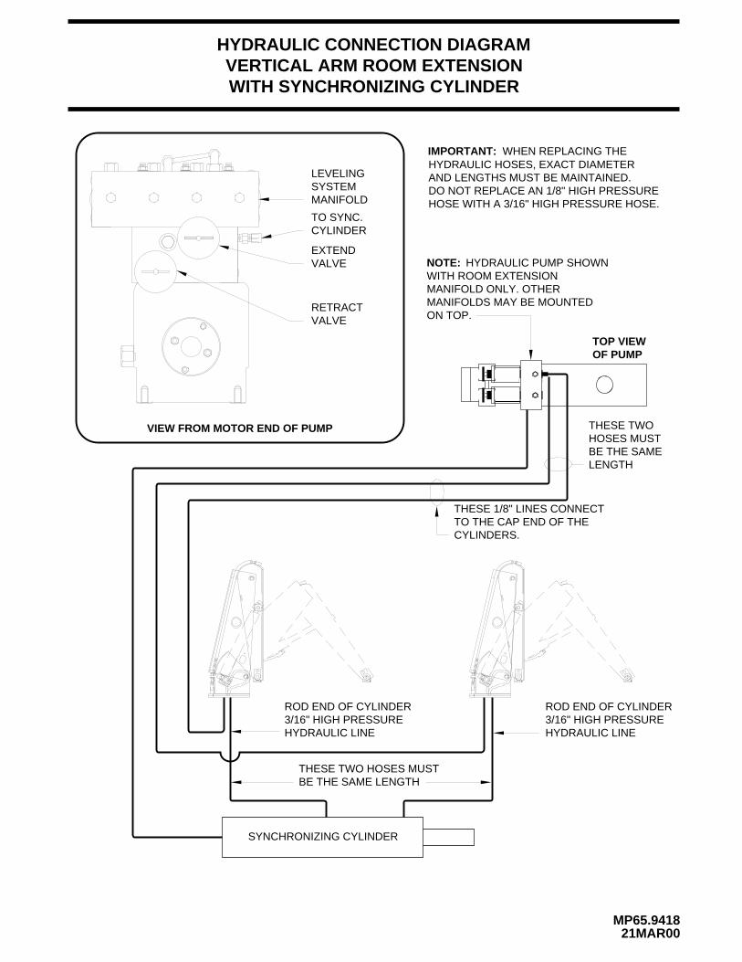
HYDRAULIC CONNECTION DIAGRAMVERTICAL ARM ROOM EXTENSION
MP65.941821MAR00
WITH SYNCHRONIZING CYLINDER
VIEW FROM MOTOR END OF PUMP
LEVELINGSYSTEMMANIFOLD
EXTENDVALVE
RETRACTVALVE
NOTE: HYDRAULIC PUMP SHOWNWITH ROOM EXTENSIONMANIFOLD ONLY. OTHERMANIFOLDS MAY BE MOUNTEDON TOP.
ROD END OF CYLINDER3/16" HIGH PRESSUREHYDRAULIC LINE HYDRAULIC LINE
3/16" HIGH PRESSUREROD END OF CYLINDER
SYNCHRONIZING CYLINDER
TOP VIEWOF PUMP
THESE 1/8" LINES CONNECTTO THE CAP END OF THECYLINDERS.
THESE TWO HOSES MUSTBE THE SAME LENGTH
THESE TWOHOSES MUSTBE THE SAMELENGTH
IMPORTANT: WHEN REPLACING THEHYDRAULIC HOSES, EXACT DIAMETERAND LENGTHS MUST BE MAINTAINED.DO NOT REPLACE AN 1/8" HIGH PRESSUREHOSE WITH A 3/16" HIGH PRESSURE HOSE.
CYLINDERTO SYNC.

HYDRAULIC FLOW DIAGRAM
MP65.945510NOV03
FIXED TOVEHICLE
FRONT CYLINDER
VERTICAL ARM OR DUAL CYLINDER ROOM EXTENSION
REAR CYLINDER
VEHICLEFIXED TO
STATIONARY POSITION
PRESSURE
RETURN
SYNCHRONIZING CYLINDER
SYNCHRONIZINGVALVE
SYNCHRONIZINGVALVE
WITH SYNCHRONIZING CYLINDER
EXTENDCYLINDER
VALVERETRACTVALVE
CYLINDER
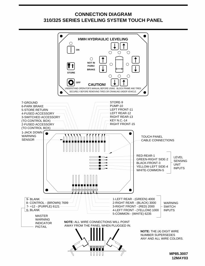
AWAY FROM THE PANEL WHEN PLUGGED IN.ALL WIRE CONNECTIONS WILL POINT
CONNECTION DIAGRAM310/325 SERIES LEVELING SYSTEM TOUCH PANEL
SECURELY BEFORE REMOVING TIRES OR CRAWLING UNDER VEHICLE.UNDERSTAND OPERATOR’S MANUAL BEFORE USING. BLOCK FRAME AND TIRES
HWH HYDRAULIC LEVELING
CAUTION!
MASTERWARNINGINDICATORPIGTAIL
7- +12 - (PURPLE) 61218- CONTROL - (BROWN) 7699
6- BLANK
9- BLANK
NOTE:
(TO CONTROL BOX)2-FUSED ACCESSORY
(TO CONTROL BOX)3-SWITCHED ACCESSORY4-FUSED ACCESSORY5-STORE RETURN6-PARK BRAKE7-GROUND
STOREBRAKE
NOT INPARK/
OFF
ON
ANY AND ALL WIRE COLORS.NUMBER SUPERSEDES
THE (4) DIGIT WIRE
CABLE CONNECTIONS
WHITE-COMMON-5YELLOW-LEFT SIDE-4
GREEN-RIGHT SIDE-2
4-LEFT FRONT - (YELLOW) 1000 5-COMMON - (WHITE) 6235
NOTE:
1-LEFT REAR - (GREEN) 40002-RIGHT REAR - (BLACK) 3000 3-RIGHT FRONT - (RED) 2000
TOUCH PANEL
BLACK-FRONT-3
RED-REAR-1
WARNINGSWITCHINPUTS
UNIT
LEVELSENSING
INPUTS
RIGHT FRONT-15KEY N.C.-14RIGHT REAR-13LEFT REAR-12LEFT FRONT-11PUMP-10STORE-9
1-JACK DOWNWARNINGSENSOR
MP85.300712MAY03
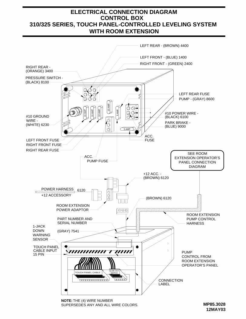
ELECTRICAL CONNECTION DIAGRAM
5 AMP
10 A
MP
10 A
MP
10 A
MP
5 A
MP
LEFT REAR - (BROWN) 4400
RIGHT FRONT - (GREEN) 2400RIGHT REAR -
PRESSURE SWITCH -
#10 POWER WIRE -(BLACK) 6100
ACC.
ACC.
RIGHT FRONT FUSE
RIGHT REAR FUSE
PUMP FUSE
PUMP - (GRAY) 8600LEFT REAR FUSE
PART NUMBER AND
10 A
MP
LEFT FRONT FUSE
LEFT FRONT - (BLUE) 1400
310/325 SERIES, TOUCH PANEL-CONTROLLED LEVELING SYSTEM
CONNECTION LABEL
PARK BRAKE -
(BLACK) 8100
CABLE INPUTTOUCH PANEL
15 PIN
TOUCH PANEL CABLESLIDE OUT
SWITCH
WITH ROOM EXTENSION
SERIAL NUMBER
(ORANGE) 3400
SEE ROOMEXTENSION OPERATOR’S
PANEL CONNECTIONDIAGRAM
POWER HARNESS
+12 ACCESSORY
ROOM EXTENSIONPOWER ADAPTOR
ROOM EXTENSIONPUMP CONTROLHARNESS
PUMPCONTROL FROMROOM EXTENSIONOPERATOR’S PANEL
(BROWN) 6120
(BROWN) 6120+12 ACC. -
FUSE
(GRAY) 7541
CONTROL BOX
(BLUE) 9000
#10 GROUNDWIRE -(WHITE) 6230
6120
NOTE: THE (4) WIRE NUMBER SUPERSEDES ANY AND ALL WIRE COLORS.
1-JACKDOWNWARNINGSENSOR
12MAY03MP85.3028
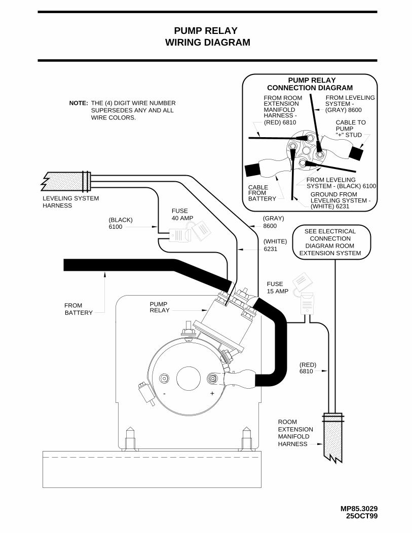
WIRING DIAGRAM
PUMPFROM
(BLACK) (GRAY)
BATTERY
LEVELING SYSTEM
FROM LEVELINGSYSTEM -
CABLE TOPUMP
GROUND FROMLEVELING SYSTEM -(WHITE) 6231
CONNECTION DIAGRAM
"+" STUD
BATTERYFROMCABLE
PUMP RELAY
(WHITE)
40 AMPFUSE
PUMP RELAY
FROM LEVELINGSYSTEM - (BLACK) 6100
EXTENSIONMANIFOLDHARNESS -
FROM ROOM
(GRAY) 8600
15 AMPFUSE
RELAY
ROOMEXTENSIONMANIFOLDHARNESS
SEE ELECTRICALCONNECTION
DIAGRAM ROOMEXTENSION SYSTEM
HARNESS
+-
6100
(RED) 6810
8600
6231
6810
25OCT99MP85.3029
NOTE: THE (4) DIGIT WIRE NUMBERSUPERSEDES ANY AND ALLWIRE COLORS.
(RED)
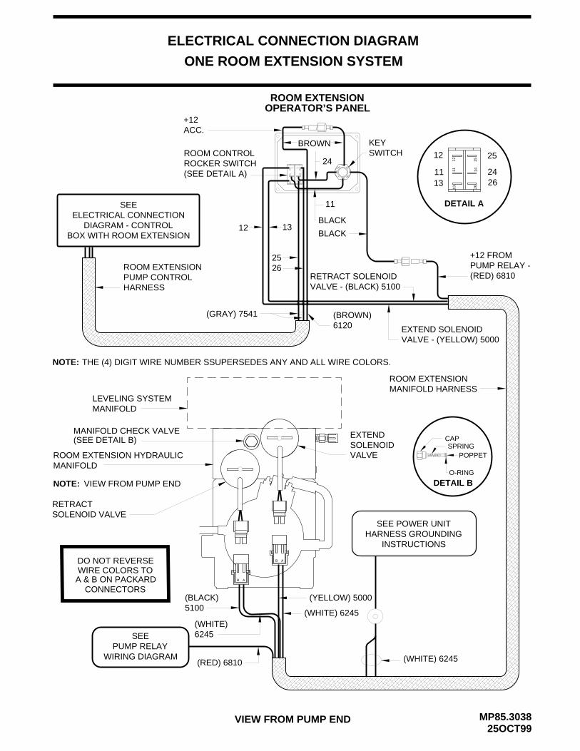
25OCT99MP85.3038
ELECTRICAL CONNECTION DIAGRAM
VIEW FROM PUMP END
ONE ROOM EXTENSION SYSTEM
ROOM EXTENSION HYDRAULICMANIFOLD
VIEW FROM PUMP END
EXTEND
RETRACT
LEVELING SYSTEMMANIFOLD
SOLENOID VALVE
SOLENOID
SEE POWER UNITHARNESS GROUNDING
INSTRUCTIONS
DO NOT REVERSE
CONNECTORS
WIRE COLORS TOA & B ON PACKARD
NOTE:
B A
B A
MANIFOLD CHECK VALVE
SEEPUMP RELAY
WIRING DIAGRAM
1311
12
2624
25 1113
2426
12 25
DETAIL A
ROOM EXTENSIONOPERATOR’S PANEL
ROOM EXTENSIONMANIFOLD HARNESS
SEEELECTRICAL CONNECTION
DIAGRAM - CONTROLBOX WITH ROOM EXTENSION
+12ACC.
BROWN
BLACK
KEYSWITCH
VALVE
ROOM CONTROLROCKER SWITCH(SEE DETAIL A)
ROOM EXTENSIONPUMP CONTROLHARNESS
DETAIL B
CAP
POPPET
O-RING
SPRING(SEE DETAIL B)
1311
12 25
2426
24
11
BLACK13
2526
12
+12 FROM PUMP RELAY -(RED) 6810RETRACT SOLENOID
VALVE - (BLACK) 5100
(GRAY) 7541 (BROWN)6120 EXTEND SOLENOID
VALVE - (YELLOW) 5000
NOTE: THE (4) DIGIT WIRE NUMBER SSUPERSEDES ANY AND ALL WIRE COLORS.
(WHITE) 6245
(YELLOW) 5000(BLACK)5100
(WHITE)6245
(RED) 6810 (WHITE) 6245

ELECTRICAL SCHEMATIC
MP85.304219JAN99
ROOM EXTENSION SYSTEM
EXTEND SOLENOID VALVE
RETRACT SOLENOID VALVE
PUMP RELAY
SWITCHKEY
(YELLOW) 5000
(BLACK) 5100
HYDRAULIC PUMP/MANIFOLD ASSEMBLY
+12 CHASSIS
15 AMPFUSE
CONTACTS
ROOM CONTROLSWITCH DPDT
ROOM EXTENSIONOPERATOR’S PANEL
(BROWN) 6120
+12 ACC. FROM
(RED) 6810
GROUNDSTUD
M
PUMP RELAY
BATTERY
CONTROL BOX -CONTROL
BOX
(GRAY)7541
(WHITE)6245
(YELLOW)5000
(WHITE)6245
(BLACK)5100
(WHITE)6231
(GRAY)8600
NOTE: THE (4) DIGIT WIRE NUMBERSUPERSEDES ANY AND ALL WIRECOLORS.
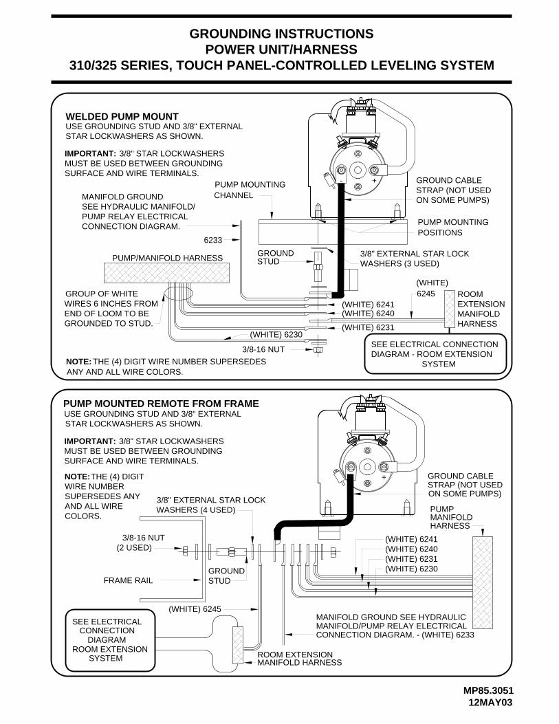
POWER UNIT/HARNESS310/325 SERIES, TOUCH PANEL-CONTROLLED LEVELING SYSTEM
+-
3/8-16 NUT
USE GROUNDING STUD AND 3/8" EXTERNALSTAR LOCKWASHERS AS SHOWN.
CHANNEL
GROUND CABLESTRAP (NOT USED
3/8-16 NUT
FRAME RAIL
(2 USED)
STRAP (NOT USED GROUND CABLE
PUMP MOUNTINGPOSITIONS
PUMP/MANIFOLD HARNESS
GROUP OF WHITEWIRES 6 INCHES FROMEND OF LOOM TO BE
ON SOME PUMPS)
ON SOME PUMPS)
-
GROUNDED TO STUD.
+
WELDED PUMP MOUNT
SURFACE AND WIRE TERMINALS.MUST BE USED BETWEEN GROUNDINGIMPORTANT: 3/8" STAR LOCKWASHERS
PUMP MOUNTED REMOTE FROM FRAME
3/8" EXTERNAL STAR LOCKWASHERS (4 USED)
STAR LOCKWASHERS AS SHOWN.USE GROUNDING STUD AND 3/8" EXTERNAL
3/8" STAR LOCKWASHERS MUST BE USED BETWEEN GROUNDINGSURFACE AND WIRE TERMINALS.
IMPORTANT:
GROUNDING INSTRUCTIONS
SEE HYDRAULIC MANIFOLD/PUMP RELAY ELECTRICALCONNECTION DIAGRAM.
CONNECTION DIAGRAM. - (WHITE) 6233MANIFOLD/PUMP RELAY ELECTRICAL
MANIFOLD GROUND
MANIFOLD GROUND SEE HYDRAULIC
SEE ELECTRICAL CONNECTIONDIAGRAM - ROOM EXTENSION
SYSTEM
CONNECTIONSEE ELECTRICAL
SYSTEM
ROOMEXTENSIONMANIFOLDHARNESS
PUMP MOUNTING
DIAGRAMROOM EXTENSION
MANIFOLD HARNESSROOM EXTENSION
(WHITE) 6245
3/8" EXTERNAL STAR LOCKWASHERS (3 USED)
GROUND STUD
6233
(WHITE) 6241(WHITE) 6240
(WHITE) 6231
(WHITE)6245
NOTE: THE (4) DIGIT WIRE NUMBER SUPERSEDES ANY AND ALL WIRE COLORS.
(WHITE) 6241(WHITE) 6240(WHITE) 6231(WHITE) 6230
PUMPMANIFOLDHARNESS
NOTE:THE (4) DIGITWIRE NUMBERSUPERSEDES ANYAND ALL WIRECOLORS.
(WHITE) 6230
GROUND STUD
MP85.305112MAY03


