Download - fortigate-ipsec-40-mr3

IPsec VPNs
FortiOS™ Handbook v3
for FortiOS 4.0 MR3

FortiOS™ Handbook IPsec VPNs
v3
11 January 2012
01-434-112804-20120111
© Copyright 2012 Fortinet, Inc. All rights reserved. Contents and terms are subject to
change by Fortinet without prior notice. Reproduction or transmission of this publication
is encouraged.
Trademarks
Copyright© 2012 Fortinet, Inc. All rights reserved. Fortinet®, FortiGate®, and
FortiGuard®, are registered trademarks of Fortinet, Inc., and other Fortinet names herein
may also be trademarks of Fortinet. All other product or company names may be
trademarks of their respective owners. Performance metrics contained herein were
attained in internal lab tests under ideal conditions, and performance may vary. Network
variables, different network environments and other conditions may affect performance
results. Nothing herein represents any binding commitment by Fortinet, and Fortinet
disclaims all warranties, whether express or implied, except to the extent Fortinet enters
a binding written contract, signed by Fortinet’s General Counsel, with a purchaser that
expressly warrants that the identified product will perform according to the performance
metrics herein. For absolute clarity, any such warranty will be limited to performance in
the same ideal conditions as in Fortinet’s internal lab tests. Fortinet disclaims in full any
guarantees. Fortinet reserves the right to change, modify, transfer, or otherwise revise this
publication without notice, and the most current version of the publication shall be
applicable.
Visit these links for more information and documentation for your Fortinet products:
Fortinet Knowledge Base - http://kb.fortinet.com
Technical Documentation - http://docs.fortinet.com
Training Services - http://campus.training.fortinet.com
Technical Support - http://support.fortinet.com
You can report errors or omissions in this or any Fortinet technical document to
F o r t i O S H a n d b o o k
F
0
h
Contents
Introduction 11
How this guide is organized . . . . . . . . . . . . . . . . . . . . . . . . . . . . . . 11
IPsec VPN concepts 13
VPN tunnels . . . . . . . . . . . . . . . . . . . . . . . . . . . . . . . . . . . . . . 13
VPN gateways . . . . . . . . . . . . . . . . . . . . . . . . . . . . . . . . . . . . . 14
Clients, servers, and peers . . . . . . . . . . . . . . . . . . . . . . . . . . . . . . . 16
Encryption . . . . . . . . . . . . . . . . . . . . . . . . . . . . . . . . . . . . . . . 17
Authentication . . . . . . . . . . . . . . . . . . . . . . . . . . . . . . . . . . . . . 17
Preshared keys . . . . . . . . . . . . . . . . . . . . . . . . . . . . . . . . 17
Additional authentication . . . . . . . . . . . . . . . . . . . . . . . . . . . 18
Phase 1 and Phase 2 settings . . . . . . . . . . . . . . . . . . . . . . . . . . . . . 18
Phase 1. . . . . . . . . . . . . . . . . . . . . . . . . . . . . . . . . . . . . . . 18
Phase 2. . . . . . . . . . . . . . . . . . . . . . . . . . . . . . . . . . . . . . . 18
Security Association . . . . . . . . . . . . . . . . . . . . . . . . . . . . . . . . . . 19
IPsec VPN Overview 21
Types of VPNs . . . . . . . . . . . . . . . . . . . . . . . . . . . . . . . . . . . . . 21
Route-based VPNs. . . . . . . . . . . . . . . . . . . . . . . . . . . . . . . . . 21
Policy-based VPNs. . . . . . . . . . . . . . . . . . . . . . . . . . . . . . . . . 22
Comparing policy-based or route-based VPNs . . . . . . . . . . . . . . . . . . 22
Planning your VPN . . . . . . . . . . . . . . . . . . . . . . . . . . . . . . . . . . . 22
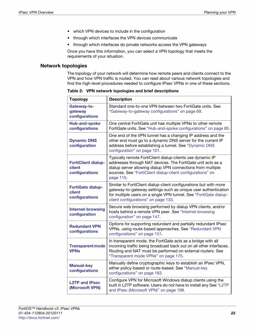
Network topologies . . . . . . . . . . . . . . . . . . . . . . . . . . . . . . . . 23
General preparation steps . . . . . . . . . . . . . . . . . . . . . . . . . . . . . . . 24
How to use this guide to configure an IPsec VPN . . . . . . . . . . . . . . . . . . . 24
IPsec VPN in the web-based manager 25Auto Key (IKE) . . . . . . . . . . . . . . . . . . . . . . . . . . . . . . . . . . . 25
Phase 1 configuration . . . . . . . . . . . . . . . . . . . . . . . . . . . . . . . 26
Phase 1 advanced configuration settings . . . . . . . . . . . . . . . . . . . 28
Phase 2 configuration . . . . . . . . . . . . . . . . . . . . . . . . . . . . . . . 31
Phase 2 advanced configuration settings . . . . . . . . . . . . . . . . . . . 31
FortiClient VPN . . . . . . . . . . . . . . . . . . . . . . . . . . . . . . . . . . . 34
Manual Key. . . . . . . . . . . . . . . . . . . . . . . . . . . . . . . . . . . . . 35
Manual key configuration settings . . . . . . . . . . . . . . . . . . . . . . . 35
Concentrator . . . . . . . . . . . . . . . . . . . . . . . . . . . . . . . . . . . . 36
IPsec Monitor . . . . . . . . . . . . . . . . . . . . . . . . . . . . . . . . . . . . . . 37
ortiOS™ Handbook v3: IPsec VPNs
1-434-112804-20120111 3ttp://docs.fortinet.com/
Contents
Auto Key phase 1 parameters 39
Overview . . . . . . . . . . . . . . . . . . . . . . . . . . . . . . . . . . . . . . . . 39
Defining the tunnel ends . . . . . . . . . . . . . . . . . . . . . . . . . . . . . . . . 40
Choosing main mode or aggressive mode . . . . . . . . . . . . . . . . . . . . . . . 40
Choosing the IKE version. . . . . . . . . . . . . . . . . . . . . . . . . . . . . . . . 41
Authenticating the FortiGate unit . . . . . . . . . . . . . . . . . . . . . . . . . . . . 41
Authenticating the FortiGate unit with digital certificates . . . . . . . . . . . . . 41
Authenticating the FortiGate unit with a pre-shared key. . . . . . . . . . . . . . 42
Authenticating remote peers and clients . . . . . . . . . . . . . . . . . . . . . . . 44
Enabling VPN access for specific certificate holders . . . . . . . . . . . . . . . 44
Before you begin. . . . . . . . . . . . . . . . . . . . . . . . . . . . . . . . 44
Configuring certificate authentication for a VPN. . . . . . . . . . . . . . . . 45
Enabling VPN access by peer identifier . . . . . . . . . . . . . . . . . . . . . . 46
Enabling VPN access with user accounts and pre-shared keys. . . . . . . . . . 47
Defining IKE negotiation parameters . . . . . . . . . . . . . . . . . . . . . . . . . . 49
Generating keys to authenticate an exchange . . . . . . . . . . . . . . . . . . 49
Defining IKE negotiation parameters. . . . . . . . . . . . . . . . . . . . . . . . 50
NAT traversal . . . . . . . . . . . . . . . . . . . . . . . . . . . . . . . . . 52
NAT keepalive frequency . . . . . . . . . . . . . . . . . . . . . . . . . . . 53
Dead peer detection . . . . . . . . . . . . . . . . . . . . . . . . . . . . . 53
Using XAuth authentication. . . . . . . . . . . . . . . . . . . . . . . . . . . . . . . 54
Using the FortiGate unit as an XAuth server . . . . . . . . . . . . . . . . . . . . 54
Using the FortiGate unit as an XAuth client . . . . . . . . . . . . . . . . . . . . 55
Phase 2 parameters 57
Basic phase 2 settings . . . . . . . . . . . . . . . . . . . . . . . . . . . . . . . . . 57
Advanced phase 2 settings. . . . . . . . . . . . . . . . . . . . . . . . . . . . . . . 57
P2 Proposals . . . . . . . . . . . . . . . . . . . . . . . . . . . . . . . . . . . . 58
Replay detection . . . . . . . . . . . . . . . . . . . . . . . . . . . . . . . . . . 58
Perfect forward secrecy (PFS)( . . . . . . . . . . . . . . . . . . . . . . . . . . . 58
Keylife . . . . . . . . . . . . . . . . . . . . . . . . . . . . . . . . . . . . . . . 58
Auto-negotiate . . . . . . . . . . . . . . . . . . . . . . . . . . . . . . . . . . . 58
Autokey Keep Alive. . . . . . . . . . . . . . . . . . . . . . . . . . . . . . . . . 59
DHCP-IPsec . . . . . . . . . . . . . . . . . . . . . . . . . . . . . . . . . . . . 59
Quick mode selectors . . . . . . . . . . . . . . . . . . . . . . . . . . . . . . . 59
Configure the phase 2 parameters . . . . . . . . . . . . . . . . . . . . . . . . . . . 60
Specifying the phase 2 parameters . . . . . . . . . . . . . . . . . . . . . . . . 60
Defining VPN security policies 63
Defining policy addresses . . . . . . . . . . . . . . . . . . . . . . . . . . . . . . . 63
Defining VPN security policies . . . . . . . . . . . . . . . . . . . . . . . . . . . . . 64
Defining an IPsec security policy for a policy-based VPN . . . . . . . . . . . . . 65
Allow outbound and allow inbound . . . . . . . . . . . . . . . . . . . . . . 65
IPsec VPNs for FortiOS 4.0 MR3
4 01-434-112804-20120111
http://docs.fortinet.com/

Contents
Outbound and inbound NAT. . . . . . . . . . . . . . . . . . . . . . . . . . 65
Source and destination addresses . . . . . . . . . . . . . . . . . . . . . . 65
Enabling other policy features . . . . . . . . . . . . . . . . . . . . . . . . . 65
Before you begin. . . . . . . . . . . . . . . . . . . . . . . . . . . . . . . . 66
Defining multiple IPsec policies for the same tunnel . . . . . . . . . . . . . 67
Defining security policies for a route-based VPN . . . . . . . . . . . . . . . . . 68
Gateway-to-gateway configurations 69
Configuration overview . . . . . . . . . . . . . . . . . . . . . . . . . . . . . . . . . 69
General configuration steps . . . . . . . . . . . . . . . . . . . . . . . . . . . . . . 71
Configuring the two VPN peers . . . . . . . . . . . . . . . . . . . . . . . . . . . . 71
Configuring Phase 1 and Phase 2 for both peers . . . . . . . . . . . . . . . . . 71
Creating security policies . . . . . . . . . . . . . . . . . . . . . . . . . . . . . 72
Creating firewall addresses . . . . . . . . . . . . . . . . . . . . . . . . . . 73
Creating route-based VPN security policies . . . . . . . . . . . . . . . . . . 74
Configuring a default route for VPN interface . . . . . . . . . . . . . . . . . 75
Creating policy-based VPN security policy . . . . . . . . . . . . . . . . . . 76
How to work with overlapping subnets . . . . . . . . . . . . . . . . . . . . . . . . 76
Solution for route-based VPN . . . . . . . . . . . . . . . . . . . . . . . . . . . 77
Solution for policy-based VPN . . . . . . . . . . . . . . . . . . . . . . . . . . . 79
Testing . . . . . . . . . . . . . . . . . . . . . . . . . . . . . . . . . . . . . . . . . 81
Hub-and-spoke configurations 85
Configuration overview . . . . . . . . . . . . . . . . . . . . . . . . . . . . . . . . . 85
Hub-and-spoke infrastructure requirements . . . . . . . . . . . . . . . . . . . 86
Spoke gateway addressing . . . . . . . . . . . . . . . . . . . . . . . . . . . . 86
Protected networks addressing . . . . . . . . . . . . . . . . . . . . . . . . . . 86
Using aggregated subnets. . . . . . . . . . . . . . . . . . . . . . . . . . . 86
Using an address group . . . . . . . . . . . . . . . . . . . . . . . . . . . . 87
Authentication . . . . . . . . . . . . . . . . . . . . . . . . . . . . . . . . . . . 87
Configure the hub . . . . . . . . . . . . . . . . . . . . . . . . . . . . . . . . . . . 87
Define the hub-spoke VPNs . . . . . . . . . . . . . . . . . . . . . . . . . . . . 87
Define the hub-spoke security policies . . . . . . . . . . . . . . . . . . . . . . 88
Configuring communication between spokes (policy-based VPN) . . . . . . . . 90
Configuring communication between spokes (route-based VPN) . . . . . . . . . 90
Using a zone as a concentrator . . . . . . . . . . . . . . . . . . . . . . . . 90
Using a zone with a policy as a concentrator . . . . . . . . . . . . . . . . . 91
Using security policies as a concentrator . . . . . . . . . . . . . . . . . . . 91
Configure the spokes . . . . . . . . . . . . . . . . . . . . . . . . . . . . . . . . . 92
Configuring security policies for hub-to-spoke communication . . . . . . . . . . 92
Policy-based VPN security policy . . . . . . . . . . . . . . . . . . . . . . 93
Configuring security policies for spoke-to-spoke communication. . . . . . . . . 93
Policy-based VPN security policy . . . . . . . . . . . . . . . . . . . . . . 94
IPsec VPNs for FortiOS 4.0 MR3
5 01-434-112804-20120111
http://docs.fortinet.com/
Contents
Dynamic spokes configuration example . . . . . . . . . . . . . . . . . . . . . . . . 95
Configure the hub (FortiGate_1) . . . . . . . . . . . . . . . . . . . . . . . . . . 95
Define the IPsec configuration . . . . . . . . . . . . . . . . . . . . . . . . . 96
Define the security policies . . . . . . . . . . . . . . . . . . . . . . . . . . 96
Configure communication between spokes . . . . . . . . . . . . . . . . . . 97
Configure the spokes . . . . . . . . . . . . . . . . . . . . . . . . . . . . . . . 98
Define the IPsec configuration . . . . . . . . . . . . . . . . . . . . . . . . . 98
Define the security policies . . . . . . . . . . . . . . . . . . . . . . . . . . 99
Dynamic DNS configuration 101
Dynamic DNS over VPN concepts . . . . . . . . . . . . . . . . . . . . . . . . . . . 101
Dynamic DNS (DDNS) . . . . . . . . . . . . . . . . . . . . . . . . . . . . . . . 101
Routing. . . . . . . . . . . . . . . . . . . . . . . . . . . . . . . . . . . . . 101
Dynamic DNS over VPN . . . . . . . . . . . . . . . . . . . . . . . . . . . . . . 102
Remote Gateway . . . . . . . . . . . . . . . . . . . . . . . . . . . . . . . 102
Local ID (peer ID). . . . . . . . . . . . . . . . . . . . . . . . . . . . . . . . 102
Route-based or policy-based VPN . . . . . . . . . . . . . . . . . . . . . . 103
Dynamic DNS topology. . . . . . . . . . . . . . . . . . . . . . . . . . . . . . . . . 103
Assumptions . . . . . . . . . . . . . . . . . . . . . . . . . . . . . . . . . . . . 104
General configuration steps . . . . . . . . . . . . . . . . . . . . . . . . . . . . . . 104
Configure the dynamically-addressed VPN peer. . . . . . . . . . . . . . . . . . . . 105
Configuring branch_2 VPN tunnel settings . . . . . . . . . . . . . . . . . . . . 105
Configuring branch_2 security policies . . . . . . . . . . . . . . . . . . . . . . 106
Define address ranges for branch_2 security policies . . . . . . . . . . . . . 107
Creating branch_2 route-based security policies . . . . . . . . . . . . . . . 107
Creating branch_2 policy-based security policies . . . . . . . . . . . . . . . 109
Configure the fixed-address VPN peer . . . . . . . . . . . . . . . . . . . . . . . . 110
Configuring branch_1 VPN tunnel settings . . . . . . . . . . . . . . . . . . . . 110
Configuring branch_1 security policies . . . . . . . . . . . . . . . . . . . . . . 111
Defining address ranges for branch_1 security policies . . . . . . . . . . . . 111
Creating branch_1 route-based security policies . . . . . . . . . . . . . . . 112
Creating branch_1 policy-based security policies . . . . . . . . . . . . . . . 113
Testing . . . . . . . . . . . . . . . . . . . . . . . . . . . . . . . . . . . . . . . . . 114
FortiClient dialup-client configurations 115
Configuration overview . . . . . . . . . . . . . . . . . . . . . . . . . . . . . . . . . 115
Peer identification . . . . . . . . . . . . . . . . . . . . . . . . . . . . . . . . . 116
Automatic configuration of FortiClient dialup clients . . . . . . . . . . . . . . . 116
One button FortiGate - to - FortiClient Phase1 VPN . . . . . . . . . . . . . . . . 117
How the FortiGate unit determines which settings to apply. . . . . . . . . . 117
Using virtual IP addresses . . . . . . . . . . . . . . . . . . . . . . . . . . . . . 118
Assigning VIPs by RADIUS user group . . . . . . . . . . . . . . . . . . . . 119
FortiClient dialup-client infrastructure requirements . . . . . . . . . . . . . . . 119
FortiClient-to-FortiGate VPN configuration steps . . . . . . . . . . . . . . . . . . . 120
IPsec VPNs for FortiOS 4.0 MR3
6 01-434-112804-20120111
http://docs.fortinet.com/
Contents
Configure the FortiGate unit . . . . . . . . . . . . . . . . . . . . . . . . . . . . . . 120
Configuring FortiGate unit VPN settings . . . . . . . . . . . . . . . . . . . . . . 120
Route-based VPN security policies . . . . . . . . . . . . . . . . . . . . . . 122
Policy-based VPN security policy . . . . . . . . . . . . . . . . . . . . . . . 122
Configuring the FortiGate unit as a VPN policy server . . . . . . . . . . . . . . . 123
Configuring DHCP service on the FortiGate unit. . . . . . . . . . . . . . . . . . 123
Configure the FortiClient Endpoint Security application . . . . . . . . . . . . . . . . 125
Configuring FortiClient to work with VPN policy distribution . . . . . . . . . . . 125
Configuring FortiClient manually . . . . . . . . . . . . . . . . . . . . . . . . . . 125
Adding XAuth authentication . . . . . . . . . . . . . . . . . . . . . . . . . . . . . . 126
FortiClient dialup-client configuration example . . . . . . . . . . . . . . . . . . . . 127
Configuring FortiGate_1 . . . . . . . . . . . . . . . . . . . . . . . . . . . . . . 127
Configuring the FortiClient Endpoint Security application . . . . . . . . . . . . . 131
FortiGate dialup-client configurations 133
Configuration overview . . . . . . . . . . . . . . . . . . . . . . . . . . . . . . . . . 133
FortiGate dialup-client infrastructure requirements . . . . . . . . . . . . . . . . 135
FortiGate dialup-client configuration steps . . . . . . . . . . . . . . . . . . . . . . 136
Configure the server to accept FortiGate dialup-client connections . . . . . . . . . . 136
Policy-based VPN security policy . . . . . . . . . . . . . . . . . . . . . . . 138
Configure the FortiGate dialup client . . . . . . . . . . . . . . . . . . . . . . . . . 138
Route-based VPN security policy . . . . . . . . . . . . . . . . . . . . . . . 139
Policy-based VPN security policy . . . . . . . . . . . . . . . . . . . . . . . 139
Supporting IKE Mode config clients 141
Automatic configuration overview . . . . . . . . . . . . . . . . . . . . . . . . . . . 141
IKE Mode Config overview . . . . . . . . . . . . . . . . . . . . . . . . . . . . . . . 141
Configuring IKE Mode Config . . . . . . . . . . . . . . . . . . . . . . . . . . . . . 142
Configuring an IKE Mode Config client . . . . . . . . . . . . . . . . . . . . . . 142
Configuring an IKE Mode Config server . . . . . . . . . . . . . . . . . . . . . . 142
IP address assignment. . . . . . . . . . . . . . . . . . . . . . . . . . . . . 143
Example: FortiGate unit as IKE Mode Config server . . . . . . . . . . . . . . . . . . 144
Example: FortiGate unit as IKE Mode Config client . . . . . . . . . . . . . . . . . . 145
Internet-browsing configuration 147
Configuration overview . . . . . . . . . . . . . . . . . . . . . . . . . . . . . . . . . 147
Creating an Internet browsing security policy . . . . . . . . . . . . . . . . . . . . . 148
Routing all remote traffic through the VPN tunnel . . . . . . . . . . . . . . . . . . . 149
Configuring a FortiGate remote peer to support Internet browsing . . . . . . . . 149
Configuring a FortiClient application to support Internet browsing . . . . . . . . 150
IPsec VPNs for FortiOS 4.0 MR3
7 01-434-112804-20120111
http://docs.fortinet.com/

Contents
Redundant VPN configurations 151
Configuration overview . . . . . . . . . . . . . . . . . . . . . . . . . . . . . . . . . 151
General configuration steps . . . . . . . . . . . . . . . . . . . . . . . . . . . . 152
Configure the VPN peers - route-based VPN . . . . . . . . . . . . . . . . . . . . . 153
Redundant route-based VPN configuration example . . . . . . . . . . . . . . . . . 155
Configuring FortiGate_1 . . . . . . . . . . . . . . . . . . . . . . . . . . . . . . 155
Configuring FortiGate_2 . . . . . . . . . . . . . . . . . . . . . . . . . . . . . . 161
Partially-redundant route-based VPN example . . . . . . . . . . . . . . . . . . . . 166
Configuring FortiGate_1 . . . . . . . . . . . . . . . . . . . . . . . . . . . . . . 168
Configuring FortiGate_2 . . . . . . . . . . . . . . . . . . . . . . . . . . . . . . 170
Creating a backup IPsec interface . . . . . . . . . . . . . . . . . . . . . . . . . . . 173
Transparent mode VPNs 175
Configuration overview . . . . . . . . . . . . . . . . . . . . . . . . . . . . . . . . . 175
Transparent VPN infrastructure requirements . . . . . . . . . . . . . . . . . . . 178
Before you begin . . . . . . . . . . . . . . . . . . . . . . . . . . . . . . . 179
Configure the VPN peers . . . . . . . . . . . . . . . . . . . . . . . . . . . . . . . 179
Manual-key configurations 183
Configuration overview . . . . . . . . . . . . . . . . . . . . . . . . . . . . . . . . . 183
Specify the manual keys for creating a tunnel . . . . . . . . . . . . . . . . . . . . . 184
IPv6 IPsec VPNs 187
Overview of IPv6 IPsec support . . . . . . . . . . . . . . . . . . . . . . . . . . . . 187
Certificates . . . . . . . . . . . . . . . . . . . . . . . . . . . . . . . . . . . . . 187
Configuring IPv6 IPsec VPNs. . . . . . . . . . . . . . . . . . . . . . . . . . . . . . 188
Phase 1 configuration . . . . . . . . . . . . . . . . . . . . . . . . . . . . . . . 188
Phase 2 configuration . . . . . . . . . . . . . . . . . . . . . . . . . . . . . . . 188
Security policies . . . . . . . . . . . . . . . . . . . . . . . . . . . . . . . . . . 188
Routing . . . . . . . . . . . . . . . . . . . . . . . . . . . . . . . . . . . . . . . 188
Site-to-site IPv6 over IPv6 VPN example . . . . . . . . . . . . . . . . . . . . . . . 189
Configure FortiGate A interfaces . . . . . . . . . . . . . . . . . . . . . . . . . . 189
Configure FortiGate A IPsec settings . . . . . . . . . . . . . . . . . . . . . . . 190
Configure FortiGate A security policies . . . . . . . . . . . . . . . . . . . . . . 190
Configure FortiGate A routing . . . . . . . . . . . . . . . . . . . . . . . . . . . 191
Configure FortiGate B . . . . . . . . . . . . . . . . . . . . . . . . . . . . . . . 191
Site-to-site IPv4 over IPv6 VPN example . . . . . . . . . . . . . . . . . . . . . . . 192
Configure FortiGate A interfaces . . . . . . . . . . . . . . . . . . . . . . . . . . 193
Configure FortiGate A IPsec settings . . . . . . . . . . . . . . . . . . . . . . . 193
Configure FortiGate A security policies . . . . . . . . . . . . . . . . . . . . . . 193
Configure FortiGate A routing . . . . . . . . . . . . . . . . . . . . . . . . . . . 194
Configure FortiGate B . . . . . . . . . . . . . . . . . . . . . . . . . . . . . . . 194
IPsec VPNs for FortiOS 4.0 MR3
8 01-434-112804-20120111
http://docs.fortinet.com/
Contents
F
0
h
Site-to-site IPv6 over IPv4 VPN example . . . . . . . . . . . . . . . . . . . . . . . 195
Configure FortiGate A interfaces . . . . . . . . . . . . . . . . . . . . . . . . . . 195
Configure FortiGate A IPsec settings . . . . . . . . . . . . . . . . . . . . . . . 196
Configure FortiGate A security policies . . . . . . . . . . . . . . . . . . . . . . 196
Configure FortiGate A routing . . . . . . . . . . . . . . . . . . . . . . . . . . . 197
Configure FortiGate B . . . . . . . . . . . . . . . . . . . . . . . . . . . . . . . 197
L2TP and IPsec (Microsoft VPN) 199
Overview . . . . . . . . . . . . . . . . . . . . . . . . . . . . . . . . . . . . . . . . 199
Layer 2 Tunneling Protocol (L2TP) . . . . . . . . . . . . . . . . . . . . . . . . . 199
Assumptions . . . . . . . . . . . . . . . . . . . . . . . . . . . . . . . . . . . . . . 200
Configuring the FortiGate unit . . . . . . . . . . . . . . . . . . . . . . . . . . . . . 200
Configuring LT2P users and firewall user group . . . . . . . . . . . . . . . . . . 200
Creating user accounts . . . . . . . . . . . . . . . . . . . . . . . . . . . . 200
Creating a user group . . . . . . . . . . . . . . . . . . . . . . . . . . . . . 201
Configuring L2TP. . . . . . . . . . . . . . . . . . . . . . . . . . . . . . . . . . 201
Configuring IPsec . . . . . . . . . . . . . . . . . . . . . . . . . . . . . . . . . 202
Configuring security policies . . . . . . . . . . . . . . . . . . . . . . . . . . . . 204
Configuring the Windows PC. . . . . . . . . . . . . . . . . . . . . . . . . . . . . . 205
Troubleshooting . . . . . . . . . . . . . . . . . . . . . . . . . . . . . . . . . . . . 206
Quick checks . . . . . . . . . . . . . . . . . . . . . . . . . . . . . . . . . . . . 207
Mac OS X and L2TP . . . . . . . . . . . . . . . . . . . . . . . . . . . . . . . . 207
Setting up logging . . . . . . . . . . . . . . . . . . . . . . . . . . . . . . . . . 207
Understanding the log messages . . . . . . . . . . . . . . . . . . . . . . . . . 208
Using the FortiGate unit debug commands . . . . . . . . . . . . . . . . . . . . 209
Typical L2TP over IPsec session startup log entries - raw format. . . . . . . 209
GRE over IPsec (Cisco VPN) configurations 211
Overview . . . . . . . . . . . . . . . . . . . . . . . . . . . . . . . . . . . . . . . . 211
Configuring the FortiGate unit . . . . . . . . . . . . . . . . . . . . . . . . . . . . . 212
Enabling overlapping subnets . . . . . . . . . . . . . . . . . . . . . . . . . . . 212
Configuring the IPsec VPN. . . . . . . . . . . . . . . . . . . . . . . . . . . . . 212
Adding IPsec tunnel end addresses . . . . . . . . . . . . . . . . . . . . . . 214
Configuring the GRE tunnel . . . . . . . . . . . . . . . . . . . . . . . . . . . . 214
Adding GRE tunnel end addresses . . . . . . . . . . . . . . . . . . . . . . 214
Configuring security policies . . . . . . . . . . . . . . . . . . . . . . . . . . . . 214
Configuring routing. . . . . . . . . . . . . . . . . . . . . . . . . . . . . . . . . 217
Configuring the Cisco router . . . . . . . . . . . . . . . . . . . . . . . . . . . . . . 217
Troubleshooting . . . . . . . . . . . . . . . . . . . . . . . . . . . . . . . . . . . . 217
Quick checks . . . . . . . . . . . . . . . . . . . . . . . . . . . . . . . . . . . . 218
Setting up logging . . . . . . . . . . . . . . . . . . . . . . . . . . . . . . . . . 218
Understanding the log messages . . . . . . . . . . . . . . . . . . . . . . . . . 218
Using diagnostic commands. . . . . . . . . . . . . . . . . . . . . . . . . . . . 219
ortiOS™ Handbook v3: IPsec VPNs
1-434-112804-20120111 9ttp://docs.fortinet.com/
Contents
Protecting OSPF with IPsec 221
Overview . . . . . . . . . . . . . . . . . . . . . . . . . . . . . . . . . . . . . . . . 221
OSPF over IPsec configuration. . . . . . . . . . . . . . . . . . . . . . . . . . . . . 222
Configuring the IPsec VPN. . . . . . . . . . . . . . . . . . . . . . . . . . . . . 222
Configuring static routing . . . . . . . . . . . . . . . . . . . . . . . . . . . . . 223
Configuring OSPF . . . . . . . . . . . . . . . . . . . . . . . . . . . . . . . . . 223
FortiGate_1 OSPF configuration . . . . . . . . . . . . . . . . . . . . . . . . 223
FortiGate_2 OSPF configuration . . . . . . . . . . . . . . . . . . . . . . . . 225
Creating a redundant configuration . . . . . . . . . . . . . . . . . . . . . . . . . . 227
Adding the second IPsec tunnel . . . . . . . . . . . . . . . . . . . . . . . . . . 227
Adding the OSPF interface. . . . . . . . . . . . . . . . . . . . . . . . . . . . . 227
Hardware offloading and acceleration 229
Overview . . . . . . . . . . . . . . . . . . . . . . . . . . . . . . . . . . . . . . . . 229
IPsec session offloading requirements. . . . . . . . . . . . . . . . . . . . . . . 229
Packet offloading requirements . . . . . . . . . . . . . . . . . . . . . . . . . . 230
IPsec encryption offloading . . . . . . . . . . . . . . . . . . . . . . . . . . . . 230
HMAC check offloading . . . . . . . . . . . . . . . . . . . . . . . . . . . . . . 230
IPsec offloading configuration examples. . . . . . . . . . . . . . . . . . . . . . . . 231
Accelerated route-based VPN configuration. . . . . . . . . . . . . . . . . . . . 231
Accelerated policy-based VPN configuration . . . . . . . . . . . . . . . . . . . 233
Monitoring and troubleshooting 235
Monitoring VPN connections . . . . . . . . . . . . . . . . . . . . . . . . . . . . . . 235
Monitoring connections to remote peers . . . . . . . . . . . . . . . . . . . . . 235
Monitoring dialup IPsec connections . . . . . . . . . . . . . . . . . . . . . . . 235
Testing VPN connections. . . . . . . . . . . . . . . . . . . . . . . . . . . . . . . . 236
Testing VPN connection . . . . . . . . . . . . . . . . . . . . . . . . . . . . . . 236
LAN interface connection . . . . . . . . . . . . . . . . . . . . . . . . . . . 237
Dialup connection . . . . . . . . . . . . . . . . . . . . . . . . . . . . . . . 237
Troubleshooting VPN connections. . . . . . . . . . . . . . . . . . . . . . . . . 237
Logging VPN events . . . . . . . . . . . . . . . . . . . . . . . . . . . . . . . . . . 239
VPN troubleshooting tips . . . . . . . . . . . . . . . . . . . . . . . . . . . . . . . . 241
The VPN proposal is not connecting . . . . . . . . . . . . . . . . . . . . . 241
General troubleshooting tips . . . . . . . . . . . . . . . . . . . . . . . . . . . . 241
A word about NAT devices. . . . . . . . . . . . . . . . . . . . . . . . . . . . . 242
Index 243
IPsec VPNs for FortiOS 4.0 MR3
10 01-434-112804-20120111
http://docs.fortinet.com/

F o r t i O S H a n d b o o k
F
0
h
IntroductionWelcome and thank you for selecting Fortinet products for your network protection. This
guide provides an overview of the IPsec VPN functionality within FortiOS on your
FortiGate unit. The first few chapters introduce you to the standards of VPN. The
remainder of the guide provides various configuration steps and options in different
situations using various FortiOS features.
How this guide is organized
This guide contains the following sections:
IPsec VPN concepts explains the basic concepts that you need to understand about
virtual private networks (VPNs).
IPsec VPN Overview provides a brief overview of IPsec technology and includes general
information about how to configure IPsec VPNs using this guide.
IPsec VPN in the web-based manager describes the IPsec VPN menu of the web-based
manager interface.
Gateway-to-gateway configurations explains how to set up a basic gateway-to-gateway
(site-to-site) IPsec VPN. In a gateway-to-gateway configuration, two FortiGate units
create a VPN tunnel between two separate private networks.
Hub-and-spoke configurations describes how to set up hub-and-spoke IPsec VPNs. In a
hub-and-spoke configuration, connections to a number of remote peers and/or clients
radiate from a single, central FortiGate hub.
Dynamic DNS configuration describes how to configure a site-to-site VPN, in which one
FortiGate unit has a static IP address and the other FortiGate unit has a dynamic IP
address and a domain name.
FortiClient dialup-client configurations guides you through configuring a FortiClient
dialup-client IPsec VPN. In a FortiClient dialup-client configuration, the FortiGate unit
acts as a dialup server and VPN client functionality is provided by the FortiClient
Endpoint Security application installed on a remote host.
FortiGate dialup-client configurations explains how to set up a FortiGate dialup-client
IPsec VPN. In a FortiGate dialup-client configuration, a FortiGate unit with a static IP
address acts as a dialup server and a FortiGate unit with a dynamic IP address initiates a
VPN tunnel with the FortiGate dialup server.
Supporting IKE Mode config clients explains how to set up a FortiGate unit as either an
IKE Mode Config server or client. IKE Mode Config is an alternative to DHCP over IPsec.
Internet-browsing configuration explains how to support secure web browsing performed
by dialup VPN clients, and hosts behind a remote VPN peer. Remote users can access
the private network behind the local FortiGate unit and browse the Internet securely. All
traffic generated remotely is subject to the security policy that controls traffic on the
private network behind the local FortiGate unit.
ortiOS™ Handbook v3: IPsec VPNs
1-434-112804-20120111 11ttp://docs.fortinet.com/
How this guide is organized Introduction
Redundant VPN configurations discusses the options for supporting redundant and
partially redundant tunnels in an IPsec VPN configuration. A FortiGate unit can be
configured to support redundant tunnels to the same remote peer if the FortiGate unit has
more than one interface to the Internet.
Transparent mode VPNs describes two FortiGate units that create a VPN tunnel between
two separate private networks transparently. In transparent mode, all FortiGate unit
interfaces except the management interface are invisible at the network layer.
Manual-key configurations explains how to manually define cryptographic keys to
establish an IPsec VPN tunnel. If one VPN peer uses specific authentication and
encryption keys to establish a tunnel, both VPN peers must use the same encryption and
authentication algorithms and keys.
IPv6 IPsec VPNs describes FortiGate unit VPN capabilities for networks based on IPv6
addressing. This includes IPv4-over-IPv6 and IPv6-over-IPv4 tunnelling configurations.
IPv6 IPsec VPNs are available in FortiOS 3.0 MR5 and later.
L2TP and IPsec (Microsoft VPN) explains how to support Microsoft Windows native VPN
clients.
GRE over IPsec (Cisco VPN) configurations explains how to interoperate with Cisco VPNs
that use Generic Routing Encapsulation (GRE) protocol with IPsec.
Protecting OSPF with IPsec provides an example of protecting OSPF links with IPsec.
Auto Key phase 1 parameters provides detailed step-by-step procedures for configuring
a FortiGate unit to accept a connection from a remote peer or dialup client. The basic
phase 1 parameters identify the remote peer or clients and support authentication
through preshared keys or digital certificates. You can increase VPN connection security
further using methods such as extended authentication (XAuth).
Phase 2 parameters provides detailed step-by-step procedures for configuring an IPsec
VPN tunnel. During phase 2, the specific IPsec security associations needed to
implement security services are selected and a tunnel is established.
Defining VPN security policies explains how to specify the source and destination IP
addresses of traffic transmitted through an IPsec VPN tunnel, and how to define a
security encryption policy. Security policies control all IP traffic passing between a source
address and a destination address.
Hardware offloading and acceleration explains how to make use of FortiASIC network
processor IPsec accelerated processing capabilities.
Monitoring and troubleshooting provides VPN monitoring and testing procedures
Where possible, this document explains how to configure VPNs using the web-based
manager. A few options can be configured only through the CLI. You can also configure
VPNs entirely through the CLI. For detailed information about CLI commands, see the
FortiGate CLI Reference.
IPsec VPNs for FortiOS 4.0 MR3
12 01-434-112804-20120111
http://docs.fortinet.com/
F o r t i O S H a n d b o o k
F
0
h
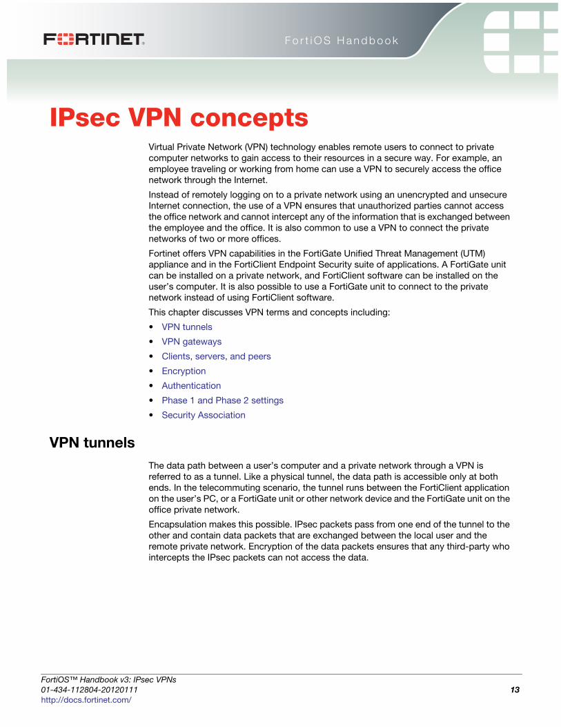
IPsec VPN conceptsVirtual Private Network (VPN) technology enables remote users to connect to private
computer networks to gain access to their resources in a secure way. For example, an
employee traveling or working from home can use a VPN to securely access the office
network through the Internet.
Instead of remotely logging on to a private network using an unencrypted and unsecure
Internet connection, the use of a VPN ensures that unauthorized parties cannot access
the office network and cannot intercept any of the information that is exchanged between
the employee and the office. It is also common to use a VPN to connect the private
networks of two or more offices.
Fortinet offers VPN capabilities in the FortiGate Unified Threat Management (UTM)
appliance and in the FortiClient Endpoint Security suite of applications. A FortiGate unit
can be installed on a private network, and FortiClient software can be installed on the
user’s computer. It is also possible to use a FortiGate unit to connect to the private
network instead of using FortiClient software.
This chapter discusses VPN terms and concepts including:
• VPN tunnels
• VPN gateways
• Clients, servers, and peers
• Encryption
• Authentication
• Phase 1 and Phase 2 settings
• Security Association
VPN tunnels
The data path between a user’s computer and a private network through a VPN is
referred to as a tunnel. Like a physical tunnel, the data path is accessible only at both
ends. In the telecommuting scenario, the tunnel runs between the FortiClient application
on the user’s PC, or a FortiGate unit or other network device and the FortiGate unit on the
office private network.
Encapsulation makes this possible. IPsec packets pass from one end of the tunnel to the
other and contain data packets that are exchanged between the local user and the
remote private network. Encryption of the data packets ensures that any third-party who
intercepts the IPsec packets can not access the data.
ortiOS™ Handbook v3: IPsec VPNs
1-434-112804-20120111 13ttp://docs.fortinet.com/
VPN gateways IPsec VPN concepts
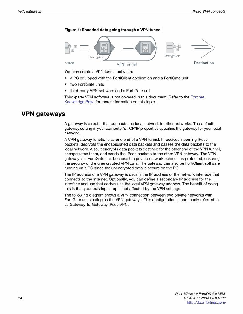
Figure 1: Encoded data going through a VPN tunnel
You can create a VPN tunnel between:
• a PC equipped with the FortiClient application and a FortiGate unit
• two FortiGate units
• third-party VPN software and a FortiGate unit
Third-party VPN software is not covered in this document. Refer to the Fortinet
Knowledge Base for more information on this topic.
VPN gateways
A gateway is a router that connects the local network to other networks. The default
gateway setting in your computer’s TCP/IP properties specifies the gateway for your local
network.
A VPN gateway functions as one end of a VPN tunnel. It receives incoming IPsec
packets, decrypts the encapsulated data packets and passes the data packets to the
local network. Also, it encrypts data packets destined for the other end of the VPN tunnel,
encapsulates them, and sends the IPsec packets to the other VPN gateway. The VPN
gateway is a FortiGate unit because the private network behind it is protected, ensuring
the security of the unencrypted VPN data. The gateway can also be FortiClient software
running on a PC since the unencrypted data is secure on the PC.
The IP address of a VPN gateway is usually the IP address of the network interface that
connects to the Internet. Optionally, you can define a secondary IP address for the
interface and use that address as the local VPN gateway address. The benefit of doing
this is that your existing setup is not affected by the VPN settings.
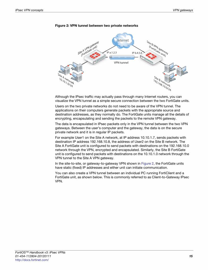
The following diagram shows a VPN connection between two private networks with
FortiGate units acting as the VPN gateways. This configuration is commonly referred to
as Gateway-to-Gateway IPsec VPN.
Decryption
VPN Tunnel
3 12
3 12
ource Destination
3 12
Encryption
3 12
IPsec VPNs for FortiOS 4.0 MR3
14 01-434-112804-20120111
http://docs.fortinet.com/
IPsec VPN concepts VPN gateways
F
0
h
Figure 2: VPN tunnel between two private networks
Although the IPsec traffic may actually pass through many Internet routers, you can
visualize the VPN tunnel as a simple secure connection between the two FortiGate units.
Users on the two private networks do not need to be aware of the VPN tunnel. The
applications on their computers generate packets with the appropriate source and
destination addresses, as they normally do. The FortiGate units manage all the details of
encrypting, encapsulating and sending the packets to the remote VPN gateway.
The data is encapsulated in IPsec packets only in the VPN tunnel between the two VPN
gateways. Between the user’s computer and the gateway, the data is on the secure
private network and it is in regular IP packets.
For example User1 on the Site A network, at IP address 10.10.1.7, sends packets with
destination IP address 192.168.10.8, the address of User2 on the Site B network. The
Site A FortiGate unit is configured to send packets with destinations on the 192.168.10.0
network through the VPN, encrypted and encapsulated. Similarly, the Site B FortiGate
unit is configured to send packets with destinations on the 10.10.1.0 network through the
VPN tunnel to the Site A VPN gateway.
In the site-to-site, or gateway-to-gateway VPN shown in Figure 2, the FortiGate units
have static (fixed) IP addresses and either unit can initiate communication.
You can also create a VPN tunnel between an individual PC running FortiClient and a
FortiGate unit, as shown below. This is commonly referred to as Client-to-Gateway IPsec
VPN.
Site B VPN gateway
(FortiGate unit)Site A VPN gateway
(FortiG
ate unit)
Site A network10.10.1.0/24
Site B network
192.168.10.0/24
IP a.1.2.3 IP b.4.5.6tewGate unit
4.5.66 A VFortiG
ateIP
VPN tunnel
ortiOS™ Handbook v3: IPsec VPNs
1-434-112804-20120111 15ttp://docs.fortinet.com/
Clients, servers, and peers IPsec VPN concepts
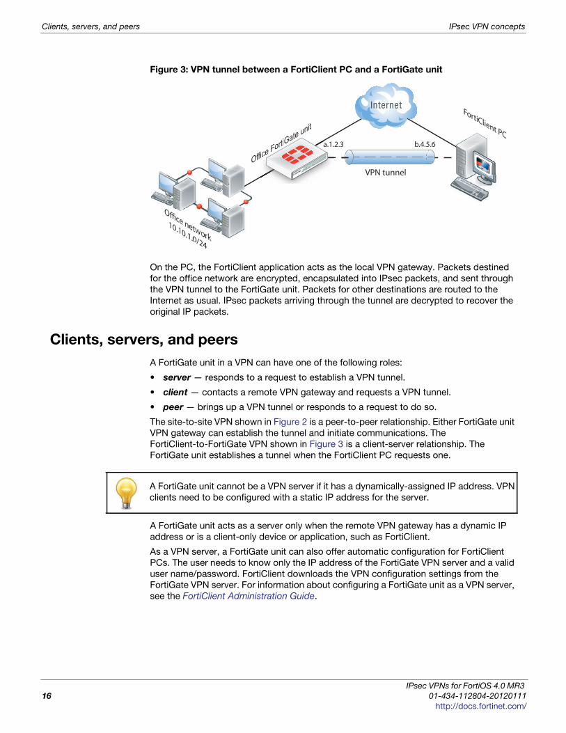
Figure 3: VPN tunnel between a FortiClient PC and a FortiGate unit
On the PC, the FortiClient application acts as the local VPN gateway. Packets destined
for the office network are encrypted, encapsulated into IPsec packets, and sent through
the VPN tunnel to the FortiGate unit. Packets for other destinations are routed to the
Internet as usual. IPsec packets arriving through the tunnel are decrypted to recover the
original IP packets.
Clients, servers, and peers
A FortiGate unit in a VPN can have one of the following roles:
• server — responds to a request to establish a VPN tunnel.
• client — contacts a remote VPN gateway and requests a VPN tunnel.
• peer — brings up a VPN tunnel or responds to a request to do so.
The site-to-site VPN shown in Figure 2 is a peer-to-peer relationship. Either FortiGate unit
VPN gateway can establish the tunnel and initiate communications. The
FortiClient-to-FortiGate VPN shown in Figure 3 is a client-server relationship. The
FortiGate unit establishes a tunnel when the FortiClient PC requests one.
A FortiGate unit acts as a server only when the remote VPN gateway has a dynamic IP
address or is a client-only device or application, such as FortiClient.
As a VPN server, a FortiGate unit can also offer automatic configuration for FortiClient
PCs. The user needs to know only the IP address of the FortiGate VPN server and a valid
user name/password. FortiClient downloads the VPN configuration settings from the
FortiGate VPN server. For information about configuring a FortiGate unit as a VPN server,
see the FortiClient Administration Guide.
FortiClient PC
Office FortiGate unit
Office network10.10.1.0/24
fice FortiGa
VPN tunnel
a.1.2.3 b.4.5.6
A FortiGate unit cannot be a VPN server if it has a dynamically-assigned IP address. VPN
clients need to be configured with a static IP address for the server.
IPsec VPNs for FortiOS 4.0 MR3
16 01-434-112804-20120111
http://docs.fortinet.com/

IPsec VPN concepts Encryption
F
0
h
Encryption
Encryption mathematically transforms data to appear as meaningless random numbers.
The original data is called plaintext and the encrypted data is called ciphertext. The
opposite process, called decryption, performs the inverse operation to recover the
original plaintext from the ciphertext.
The process by which the plaintext is transformed to ciphertext and back again is called
an algorithm. All algorithms use a small piece of information, a key, in the arithmetic
process of converted plaintext to ciphertext, or vice-versa. IPsec uses symmetrical
algorithms, in which the same key is used to both encrypt and decrypt the data.
The security of an encryption algorithm is determined by the length of the key that it uses.
FortiGate IPsec VPNs offer the following encryption algorithms, in descending order of
security:
There is a human factor in the security of encryption. The key must be kept secret, known
only to the sender and receiver of the messages. Also, the key must not be something
that unauthorized parties might easily guess, such as the sender’s name, birthday or
simple sequence such as 123456.
Authentication
In addition to protecting data through encryption, a VPN must ensure that only authorized
users can access the private network. You must use either a preshared key on both VPN
gateways or RSA X.509 security certificates. The examples in this guide use only
preshared key authentication. Refer to the Fortinet Knowledge Base for articles on RSA
X.509 security certificates.
Preshared keysA preshared key contains at least six random alphanumeric characters. Users of the VPN
must obtain the preshared key from the person who manages the VPN server and add
the preshared key to their VPN client configuration.
Although it looks like a password, the preshared key, also known as a shared secret, is
never sent by either gateway. The preshared key is used in the calculations at each end
that generate the encryption keys. As soon as the VPN peers attempt to exchange
encrypted data, preshared keys that do not match will cause the process to fail.
AES256 A 128-bit block algorithm that uses a 256-bit key.
AES192 A 128-bit block algorithm that uses a 192-bit key.
AES128 A 128-bit block algorithm that uses a 128-bit key.
3DES Triple-DES, in which plain text is DES-encrypted three times by three keys.
DES Digital Encryption Standard, a 64-bit block algorithm that uses a 56-bit
key
The default encryption algorithms provided on FortiGate units make recovery of
encrypted data almost impossible without the proper encryption keys.
ortiOS™ Handbook v3: IPsec VPNs
1-434-112804-20120111 17ttp://docs.fortinet.com/
Phase 1 and Phase 2 settings IPsec VPN concepts
Additional authenticationTo increase security, you can require additional means of authentication from users:
• an identifier, called a peer ID or a local ID
• extended authentication (XAUTH) which imposes an additional user name/password
requirement
A Local ID is an alphanumeric value assigned in the Phase 1 configuration. The Local ID
of a peer is called a Peer ID.
Phase 1 and Phase 2 settings
A VPN tunnel is established in two phases: Phase 1 and Phase 2. Several parameters
determine how this is done. Except for IP addresses, the settings simply need to match
at both VPN gateways. There are defaults that are appropriate for most cases.
Phase 1
In Phase 1, the two VPN gateways exchange information about the encryption algorithms
that they support and then establish a temporary secure connection to exchange
authentication information.
When you configure your FortiGate unit or FortiClient application, you must specify the
following settings for Phase 1:
All other Phase 1 settings have default values. These settings mainly configure the types
of encryption to be used. The default settings on FortiGate units and in the FortiClient
application are compatible. The examples in this guide use these defaults.
For more detailed information about Phase 1 settings, see the “Auto Key phase 1
parameters” on page 39.
Phase 2
Similar to the Phase 1 process, the two VPN gateways exchange information about the
encryption algorithms that they support for Phase 2. You may choose different encryption
for Phase 1 and Phase 2. If both gateways have at least one encryption algorithm in
common, a VPN tunnel can be established. Keep in mind that more algorithms each
phase does not share with the other gateway, the longer negotiations will take. In extreme
cases this may cause timeouts during negotiations.
FortiClient distinguishes between Phase 1 and Phase 2 only in the VPN Advanced
settings and uses different terms. Phase 1 is called the IKE Policy. Phase 2 is called the
IPsec Policy.
Remote Gateway
The remote VPN gateway’s address.
FortiGate units also have the option of operating only as a
server by selecting the “Dialup User” option.
Preshared keyThis must be the same at both ends. It is used to encrypt
phase 1 authentication information.
Local interfaceThe network interface that connects to the other VPN
gateway. This applies on a FortiGate unit only.
IPsec VPNs for FortiOS 4.0 MR3
18 01-434-112804-20120111
http://docs.fortinet.com/

IPsec VPN concepts Security Association
F
0
h
To configure default Phase 2 settings on a FortiGate unit, you need only select the name
of the corresponding Phase 1 configuration. In FortiClient, no action is required to enable
default Phase 2 settings.
For more detailed information about Phase 2 settings, see “Phase 2 parameters” on
page 57.
Security Association
The establishment of a Security Association (SA) is the successful outcome of Phase 1
negotiations. Each peer maintains a database of information about VPN connections. The
information in each SA can include cryptographic algorithms and keys, keylife, and the
current packet sequence number. This information is kept synchronized as the VPN
operates. Each SA has a Security Parameter Index (SPI) that is provided to the remote
peer at the time the SA is established. Subsequent IPsec packets from the peer always
reference the relevant SPI. It is possible for peers to have multiple VPNs active
simultaneously, and correspondingly multiple SPIs.
ortiOS™ Handbook v3: IPsec VPNs
1-434-112804-20120111 19ttp://docs.fortinet.com/

Security Association IPsec VPN concepts
IPsec VPNs for FortiOS 4.0 MR3
20 01-434-112804-20120111
http://docs.fortinet.com/

F o r t i O S H a n d b o o k
F
0
h
IPsec VPN OverviewThis section provides a brief overview of IPsec technology and includes general
information about how to configure IPsec VPNs using this guide.
The following topics are included in this section:
• Types of VPNs
• Planning your VPN
• General preparation steps
• How to use this guide to configure an IPsec VPN
VPN configurations interact with the firewall component of the FortiGate unit. There must
be a security policy in place to permit traffic to pass between the private network and the
VPN tunnel.
Security policies for VPNs specify:
• the FortiGate interface that provides the physical connection to the remote VPN
gateway, usually an interface connected to the Internet
• the FortiGate interface that connects to the private network
• IP addresses associated with data that has to be encrypted and decrypted
• optionally, a schedule that restricts when the VPN can operate
• optionally, the services (types of data) that can be sent
When the first packet of data that meets all of the conditions of the security policy arrives
at the FortiGate unit, a VPN tunnel may be initiated and the encryption or decryption of
data is performed automatically afterward. For more information, see “Defining VPN
security policies” on page 63.
Types of VPNs
FortiGate unit VPNs can be policy-based or route-based. There is little difference
between the two types. In both cases, you specify phase 1 and phase 2 settings.
However there is a difference in implementation. A route-based VPN creates a virtual
IPsec network interface that applies encryption or decryption as needed to any traffic
that it carries. That is why route-based VPNs are also known as interface-based VPNs. A
policy-based VPN is implemented through a special security policy that applies the
encryption you specified in the phase 1 and phase 2 settings.
Route-based VPNs
For a route-based VPN, you create two security policies between the virtual IPsec
interface and the interface that connects to the private network. In one policy the virtual
interface is the source. In the other policy the virtual interface is the destination. The
Action for both policies is Accept. This creates bidirectional policies that ensure traffic will
flow in both directions over the VPN.
ortiOS™ Handbook v3: IPsec VPNs
1-434-112804-20120111 21ttp://docs.fortinet.com/

Planning your VPN IPsec VPN Overview
Policy-based VPNs
For a policy-based VPN, one security policy enables communication in both directions.
You must select IPSEC as the Action and then select the VPN tunnel you defined in the
phase 1 settings. You can then enable inbound and outbound traffic as needed within
that policy, or create multiple policies of this type to handle different types of traffic
differently. For example HTTPS traffic may not require the same level of scanning as FTP
traffic.
Comparing policy-based or route-based VPNs
For both VPN types you create phase 1 and phase 2 configurations. Both types are
handled in the stateful inspection security layer, assuming there is no IPS or AV. For more
information on the three security layers, see the FortiOS Troubleshooting guide.
The main difference is in the security policy.
You create a policy-based VPN by defining an IPSEC security policy between two
network interfaces and associating it with the VPN tunnel (phase 1) configuration.
You create a route-based VPN by enabling IPsec interface mode in the VPN phase 1
configuration. This creates a virtual IPsec interface. You then define a regular ACCEPT
security policy to permit traffic to flow between the virtual IPsec interface and another
network interface. And lastly, configure a static route to allow traffic over the VPN.
Where possible, you should create route-based VPNs. Generally, route-based VPNs are
more flexible and easier to configure than policy-based VPNs — by default they are
treated as interfaces. However, these two VPN types have different requirements that
limit where they can be used.
Planning your VPN
It is a good idea to plan the VPN configuration ahead of time. This will save time later and
be help you configure your VPN correctly.
All VPN configurations comprise a number of required and optional parameters. Before
you begin, you need to determine:
• where does the IP traffic originate and where does it need to be delivered
• which hosts, servers, or networks to include in the VPN
Table 1: Comparison of policy-based and route-based VPNs
Features Policy-based Route-based
• Both NAT and
transparent modes
available
• Yes • NAT mode only
• L2TP-over-IPsec
supported
• Yes • No
• GRE-over-IPsec
supported
• No • Yes
• security policy
requirements
• Requires a security policy
with IPSEC action that
specifies the VPN tunnel
• Requires only a simple
security policy with
ACCEPT action
• Number of policies
per VPN
• One policy controls
connections in both
directions
• A separate policy is
required for connections in
each direction
IPsec VPNs for FortiOS 4.0 MR3
22 01-434-112804-20120111
http://docs.fortinet.com/
IPsec VPN Overview Planning your VPN
F
0
h
• which VPN devices to include in the configuration
• through which interfaces the VPN devices communicate
• through which interfaces do private networks access the VPN gateways
Once you have this information, you can select a VPN topology that meets the
requirements of your situation.
Network topologies
The topology of your network will determine how remote peers and clients connect to the
VPN and how VPN traffic is routed. You can read about various network topologies and
find the high-level procedures needed to configure IPsec VPNs in one of these sections.
Table 2: VPN network topologies and brief descriptions
Topology Description
Gateway-to-
gateway
configurations
Standard one-to-one VPN between two FortiGate units. See
“Gateway-to-gateway configurations” on page 69.
Hub-and-spoke
configurations
One central FortiGate unit has multiple VPNs to other remote
FortiGate units. See “Hub-and-spoke configurations” on page 85.
Dynamic DNS
configuration
One end of the VPN tunnel has a changing IP address and the
other end must go to a dynamic DNS server for the current IP
address before establishing a tunnel. See “Dynamic DNS
configuration” on page 101.
FortiClient dialup-
client
configurations
Typically remote FortiClient dialup-clients use dynamic IP
addresses through NAT devices. The FortiGate unit acts as a
dialup server allowing dialup VPN connections from multiple
sources. See “FortiClient dialup-client configurations” on
page 115.
FortiGate dialup-
client
configurations
Similar to FortiClient dialup-client configurations but with more
gateway-to-gateway settings such as unique user authentication
for multiple users on a single VPN tunnel. See “FortiGate dialup-
client configurations” on page 133.
Internet-browsing
configuration
Secure web browsing performed by dialup VPN clients, and/or
hosts behind a remote VPN peer. See “Internet-browsing
configuration” on page 147.
Redundant VPN
configurations
Options for supporting redundant and partially redundant IPsec
VPNs, using route-based approaches. See “Redundant VPN
configurations” on page 151.
Transparent mode
VPNs
In transparent mode, the FortiGate acts as a bridge with all
incoming traffic being broadcast back out on all other interfaces.
Routing and NAT must be performed on external routers. See
“Transparent mode VPNs” on page 175.
Manual-key
configurations
Manually define cryptographic keys to establish an IPsec VPN,
either policy-based or route-based. See “Manual-key
configurations” on page 183.
L2TP and IPsec
(Microsoft VPN)
Configure VPN for Microsoft Windows dialup clients using the
built in L2TP software. Users do not have to install any See “L2TP
and IPsec (Microsoft VPN)” on page 199.
ortiOS™ Handbook v3: IPsec VPNs
1-434-112804-20120111 23ttp://docs.fortinet.com/
General preparation steps IPsec VPN Overview
These sections contain high-level configuration guidelines with cross-references to
detailed configuration procedures. If you need more detail to complete a step, select the
cross-reference in the step to drill-down to more detail. Return to the original procedure
to complete the procedure. For a general overview of how to configure a VPN, see
“General preparation steps” below.
General preparation steps
A VPN configuration defines relationships between the VPN devices and the private
hosts, servers, or networks making up the VPN. Configuring a VPN involves gathering
and recording the following information. You will need this information to configure the
VPN.
• The private IP addresses of participating hosts, servers, and/or networks. These
IP addresses represent the source addresses of traffic that is permitted to pass
through the VPN. A IP source address can be an individual IP address, an address
range, or a subnet address.
• The public IP addresses of the VPN end-point interfaces. The VPN devices
establish tunnels with each other through these interfaces.
• The private IP addresses associated with the VPN-device interfaces to the
private networks. Computers on the private networks behind the VPN gateways will
connect to their VPN gateways through these interfaces.
How to use this guide to configure an IPsec VPN
This guide uses a task-based approach to provide all of the procedures needed to create
different types of VPN configurations. Follow the step-by-step configuration procedures
in this guide to set up the VPN.
The following configuration procedures are common to all IPsec VPNs:
1 Define the phase 1 parameters that the FortiGate unit needs to authenticate remote
peers or clients and establish a secure a connection. See “Auto Key phase 1
parameters” on page 39.
2 Define the phase 2 parameters that the FortiGate unit needs to create a VPN tunnel
with a remote peer or dialup client. See “Phase 2 parameters” on page 57.
3 Specify the source and destination addresses of IP packets that are to be transported
through the VPN tunnel. See “Defining policy addresses” on page 63.
4 Create an IPsec security policy to define the scope of permitted services between the
IP source and destination addresses. See “Defining VPN security policies” on
page 64.
These steps assume you configure the FortiGate unit to generate unique IPsec encryption
and authentication keys automatically. In situations where a remote VPN peer or client
requires a specific IPsec encryption and authentication key, you must configure the
FortiGate unit to use manual keys instead of performing Steps 1 and 2. For more
information, see “Manual-key configurations” on page 183.
IPsec VPNs for FortiOS 4.0 MR3
24 01-434-112804-20120111
http://docs.fortinet.com/
F o r t i O S H a n d b o o k
F
0
h
IPsec VPN in the web-based manager
The IPsec VPN menu in FortiOS provides settings to configure an IPsec VPN. IPsec VPNs
that are configured by using the general procedure:
1 Define phase 1 parameters to authenticate remote peers and clients for a secure
connection. See “Phase 1 configuration” on page 26.
2 Define phase 2 parameters to create a VPN tunnel with a remote peer or dialup client.
See “Phase 2 configuration” on page 31.
3 Create a security policy to permit communication between your private network and
the VPN. Policy-based VPNs have an action of IPSEC, where for interface-based
VPNs the security policy action is ACCEPT. See “Defining VPN security policies” on
page 63.
The FortiGate unit implements the Encapsulated Security Payload (ESP) protocol.
Internet Key Exchange (IKE) is performed automatically based on pre-shared keys or
X.509 digital certificates. As an option, you can specify manual keys. Interface mode,
supported in NAT mode only, creates a virtual interface for the local end of a VPN tunnel.
This topic contains the following:
• Auto Key (IKE)
• Manual Key
• Concentrator
Auto Key (IKE)
You can configure VPN peers (or a FortiGate dialup server and a VPN client) to generate
unique Internet Key Exchange (IKE) keys automatically during the IPsec phase 1 and
phase 2 exchanges.
When you define phase 2 parameters, you can choose any set of phase 1 parameters to
set up a secure connection for the tunnel and authenticate the remote peer. Auto Key
configuration applies to both tunnel-mode and interface-mode VPNs.
With these steps, your FortiGate unit will automatically generate unique IPsec encryption
and authentication keys. If a remote VPN peer or client requires a specific IPsec
encryption or authentication key, you must configure your FortiGate unit to use manual
keys instead. See “Manual Key” on page 35.
ortiOS™ Handbook v3: IPsec VPNs
1-434-112804-20120111 25ttp://docs.fortinet.com/

IPsec VPN in the web-based manager
To configure VPN peers go to VPN > IPsec > Auto Key (IKE).
Phase 1 configuration
The basic phase 1 settings associate IPsec phase 1 parameters with a remote gateway, if
a pre-shared key or digital certificate will be used, and if a special identifier will be used to
identify the remote VPN peer or client.
Auto Key (IKE) page
Create Phase 1Creates a new phase 1 tunnel configuration. For more information,
see “Phase 1 configuration” on page 26.
Create Phase 2Creates a new phase 2 configuration. For more information, see
“Phase 2 configuration” on page 31.
Create FortiClient
VPN
Creates a new FortiClient VPN. For more information, see
“FortiClient VPN” on page 34.
If you want to control how the IKE negotiation process controls traffic when there is no
traffic, as well as the length of time the FortiGate unit waits for negotiations to occur, use
the negotiation-timeout and auto-negotiation commands in the CLI.
New Phase 1 page
Name
Type a name for the phase 1 definition. The maximum name
length is 15 characters for an interface mode VPN, 35 characters
for a policy-based VPN. If Remote Gateway is Dialup User, the
maximum name length is further reduced depending on the
number of dialup tunnels that can be established: by 2 for up to 9
tunnels, by 3 for up to 99 tunnels, 4 for up to 999 tunnels, and so
on.
For a tunnel mode VPN, the name normally reflects where the
remote connection originates. For a route-based tunnel, the
FortiGate unit also uses the name for the virtual IPsec interface
that it creates automatically.
Remote Gateway
Select the category of the remote connection:
• Static IP Address — If the remote peer has a static IP address.
• Dialup User — If one or more FortiClient or FortiGate dialup
clients with dynamic IP addresses will connect to the FortiGate
unit.
• Dynamic DNS — If a remote peer that has a domain name and
subscribes to a dynamic DNS service will connect to the
FortiGate unit.
IP AddressIf you selected Static IP Address, enter the IP address of the
remote peer.
Dynamic DNSIf you selected Dynamic DNS, enter the domain name of the
remote peer.
IPsec VPNs for FortiOS 4.0 MR3
26 01-434-112804-20120111
http://docs.fortinet.com/
IPsec VPN in the web-based manager
F
0
h
Local Interface
This option is available in NAT mode only. Select the name of the
interface through which remote peers or dialup clients connect to
the FortiGate unit.
By default, the local VPN gateway IP address is the IP address of
the interface that you selected. Optionally, you can specify a
unique IP address for the VPN gateway in the Advanced settings.
Mode
Select Main (ID Protection) or Aggressive:
• Main mode — the phase 1 parameters are exchanged in
multiple rounds with encrypted authentication information.
• Aggressive mode — the phase 1 parameters are exchanged in
single message with authentication information that is not
encrypted.
When the remote VPN peer has a dynamic IP address and is
authenticated by a pre-shared key, you must select Aggressive
mode if there is more than one dialup phase1 configuration for the
interface IP address.
When the remote VPN peer has a dynamic IP address and is
authenticated by a certificate, you must select Aggressive mode if
there is more than one phase 1 configuration for the interface IP
address and these phase 1 configurations use different proposals.
Authentication
Method
Select Preshared Key or RSA Signature.
Pre-shared Key
If you selected Pre-shared Key, enter the pre-shared key that the
FortiGate unit will use to authenticate itself to the remote peer or
dialup client during phase 1 negotiations. You must define the
same key at the remote peer or client. The key must contain at
least 6 printable characters. For optimum protection against
currently known attacks, the key must consist of a minimum of 16
randomly chosen alphanumeric characters.
Certificate Name
If you selected RSA Signature, select the name of the server
certificate that the FortiGate unit will use to authenticate itself to
the remote peer or dialup client during phase 1 negotiations. For
information about obtaining and loading the required server
certificate, see the FortiOS User Authentication guide.
Peer Options
Peer options are available to authenticate VPN peers or clients,
depending on the Remote Gateway and Authentication Method
settings.
Accept any peer ID
Accept the local ID of any remote VPN peer or client. The
FortiGate unit does not check identifiers (local IDs). You can set
Mode to Aggressive or Main.
You can use this option with RSA Signature authentication. But,
for highest security, configure a PKI user/group for the peer and
set Peer Options to Accept this peer certificate only.
ortiOS™ Handbook v3: IPsec VPNs
1-434-112804-20120111 27ttp://docs.fortinet.com/
IPsec VPN in the web-based manager
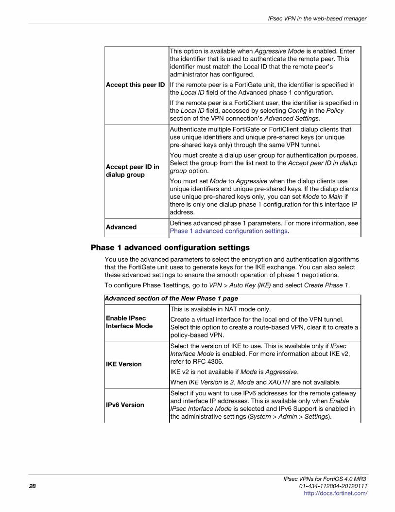
Phase 1 advanced configuration settingsYou use the advanced parameters to select the encryption and authentication algorithms
that the FortiGate unit uses to generate keys for the IKE exchange. You can also select
these advanced settings to ensure the smooth operation of phase 1 negotiations.
To configure Phase 1settings, go to VPN > Auto Key (IKE) and select Create Phase 1.
Accept this peer ID
This option is available when Aggressive Mode is enabled. Enter
the identifier that is used to authenticate the remote peer. This
identifier must match the Local ID that the remote peer’s
administrator has configured.
If the remote peer is a FortiGate unit, the identifier is specified in
the Local ID field of the Advanced phase 1 configuration.
If the remote peer is a FortiClient user, the identifier is specified in
the Local ID field, accessed by selecting Config in the Policy
section of the VPN connection’s Advanced Settings.
Accept peer ID in
dialup group
Authenticate multiple FortiGate or FortiClient dialup clients that
use unique identifiers and unique pre-shared keys (or unique
pre-shared keys only) through the same VPN tunnel.
You must create a dialup user group for authentication purposes.
Select the group from the list next to the Accept peer ID in dialup
group option.
You must set Mode to Aggressive when the dialup clients use
unique identifiers and unique pre-shared keys. If the dialup clients
use unique pre-shared keys only, you can set Mode to Main if
there is only one dialup phase 1 configuration for this interface IP
address.
AdvancedDefines advanced phase 1 parameters. For more information, see
Phase 1 advanced configuration settings.
Advanced section of the New Phase 1 page
Enable IPsec
Interface Mode
This is available in NAT mode only.
Create a virtual interface for the local end of the VPN tunnel.
Select this option to create a route-based VPN, clear it to create a
policy-based VPN.
IKE Version
Select the version of IKE to use. This is available only if IPsec
Interface Mode is enabled. For more information about IKE v2,
refer to RFC 4306.
IKE v2 is not available if Mode is Aggressive.
When IKE Version is 2, Mode and XAUTH are not available.
IPv6 Version
Select if you want to use IPv6 addresses for the remote gateway
and interface IP addresses. This is available only when Enable
IPsec Interface Mode is selected and IPv6 Support is enabled in
the administrative settings (System > Admin > Settings).
IPsec VPNs for FortiOS 4.0 MR3
28 01-434-112804-20120111
http://docs.fortinet.com/

IPsec VPN in the web-based manager
F
0
h
Local Gateway IP
If you selected Enable IPsec Interface Mode, specify an IP
address for the local end of the VPN tunnel. Select one of the
following:
• Main Interface IP — The FortiGate unit obtains the IP address
of the interface from the network interface settings.
• Specify — Enter a secondary address of the interface selected
in the phase 1 Local Interface field. For more information, see
“Local Interface” on page 27.
You cannot configure Interface mode in a transparent mode
VDOM.
P1 Proposal
Select the encryption and authentication algorithms used to
generate keys for protecting negotiations and add encryption and
authentication algorithms as required.
You need to select a minimum of one and a maximum of three
combinations. The remote peer or client must be configured to
use at least one of the proposals that you define.
Select one of the following symmetric-key encryption algorithms:
• DES — Digital Encryption Standard, a 64-bit block algorithm
that uses a 56-bit key.
• 3DES — Triple-DES, in which plain text is encrypted three
times by three keys.
• AES128 — a 128-bit block Cipher Block Chaining (CBC)
algorithm that uses a 128-bit key.
• AES192 — a 128-bit block Cipher Block Chaining (CBC)
algorithm that uses a 192-bit key.
• AES256 — a 128-bit block Cipher Block Chaining (CBC)
algorithm that uses a 256-bit key.
Select either of the following authentication message digests to
check the authenticity of messages during phase 1 negotiations:
• MD5 — Message Digest 5, the hash algorithm developed by
RSA Data Security.
• SHA1 — Secure Hash Algorithm 1, which produces a 160-bit
message digest.
• SHA256 — Secure Hash Algorithm 2, which produces a 256-
bit message digest.
To specify a third combination, use the Add button beside the
fields for the second combination.
DH Group
Select one or more Diffie-Hellman groups from DH group 1, 2, 5
and 14. At least one of the DH Group settings on the remote peer
or client must match one the selections on the FortiGate unit.
Failure to match one or more DH groups will result in failed
negotiations.
Keylife
Enter the time (in seconds) that must pass before the IKE
encryption key expires. When the key expires, a new key is
generated without interrupting service. The keylife can be from
120 to 172 800 seconds.
ortiOS™ Handbook v3: IPsec VPNs
1-434-112804-20120111 29ttp://docs.fortinet.com/
IPsec VPN in the web-based manager
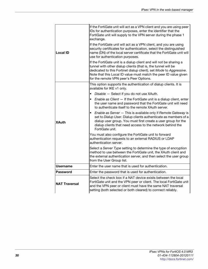
Local ID
If the FortiGate unit will act as a VPN client and you are using peer
IDs for authentication purposes, enter the identifier that the
FortiGate unit will supply to the VPN server during the phase 1
exchange.
If the FortiGate unit will act as a VPN client, and you are using
security certificates for authentication, select the distinguished
name (DN) of the local server certificate that the FortiGate unit will
use for authentication purposes.
If the FortiGate unit is a dialup client and will not be sharing a
tunnel with other dialup clients (that is, the tunnel will be
dedicated to this Fortinet dialup client), set Mode to Aggressive.
Note that this Local ID value must match the peer ID value given
for the remote VPN peer’s Peer Options.
XAuth
This option supports the authentication of dialup clients. It is
available for IKE v1 only.
• Disable — Select if you do not use XAuth.
• Enable as Client — If the FortiGate unit is a dialup client, enter
the user name and password that the FortiGate unit will need
to authenticate itself to the remote XAuth server.
• Enable as Server — This is available only if Remote Gateway is
set to Dialup User. Dialup clients authenticate as members of a
dialup user group. You must first create a user group for the
dialup clients that need access to the network behind the
FortiGate unit.
You must also configure the FortiGate unit to forward
authentication requests to an external RADIUS or LDAP
authentication server.
Select a Server Type setting to determine the type of encryption
method to use between the FortiGate unit, the XAuth client and
the external authentication server, and then select the user group
from the User Group list.
Username Enter the user name that is used for authentication.
Password Enter the password that is used for authentication.
NAT Traversal
Select the check box if a NAT device exists between the local
FortiGate unit and the VPN peer or client. The local FortiGate unit
and the VPN peer or client must have the same NAT traversal
setting (both selected or both cleared) to connect reliably.
IPsec VPNs for FortiOS 4.0 MR3
30 01-434-112804-20120111
http://docs.fortinet.com/

IPsec VPN in the web-based manager
F
0
h
Phase 2 configuration
After IPsec phase 1 negotiations end successfully, you begin phase 2. You configure the
phase 2 parameters to define the algorithms that the FortiGate unit may use to encrypt
and transfer data for the remainder of the session. During phase 2, you select specific
IPsec security associations needed to implement security services and establish a
tunnel.
The basic phase 2 settings associate IPsec phase 2 parameters with the phase 1
configuration that specifies the remote end point of the VPN tunnel. In most cases, you
need to configure only basic phase 2 settings.
To configure Phase 2 settings, go to VPN > Auto Key (IKE) and select Create Phase 2.
Phase 2 advanced configuration settingsIn phase 2, the FortiGate unit and the VPN peer or client exchange keys again to
establish a secure communication channel between them. You select the encryption and
authentication algorithms needed to generate keys for protecting the implementation
details of Security Associations (SAs). These are called P2 Proposal parameters. The
keys are generated automatically using a Diffie-Hellman algorithm.
You can use a number of additional advanced phase 2 settings to enhance the operation
of the tunnel.
Keepalive
Frequency
If you enabled NAT-traversal, enter a keepalive frequency setting.
Dead Peer
Detection
Select this check box to reestablish VPN tunnels on idle
connections and clean up dead IKE peers if required. You can use
this option to receive notification whenever a tunnel goes up or
down, or to keep the tunnel connection open when no traffic is
being generated inside the tunnel. For example, in scenarios
where a dialup client or dynamic DNS peer connects from an IP
address that changes periodically, traffic may be suspended while
the IP address changes.
With Dead Peer Detection selected, you can use the config vpn ipsec phase1 (tunnel mode) or config vpn ipsec phase1-interface (interface mode) CLI command to optionally specify
a retry count and a retry interval.
New Phase 2 page
Name Type a name to identify the phase 2 configuration.
Phase 1
Select the phase 1 tunnel configuration. For more information on
configuring phase 1, see “Phase 1 configuration” on page 26. The
phase 1 configuration describes how remote VPN peers or clients will be
authenticated on this tunnel, and how the connection to the remote peer
or client will be secured.
AdvancedDefine advanced phase 2 parameters. For more information, see
“Phase 2 advanced configuration settings” on page 31.
ortiOS™ Handbook v3: IPsec VPNs
1-434-112804-20120111 31ttp://docs.fortinet.com/
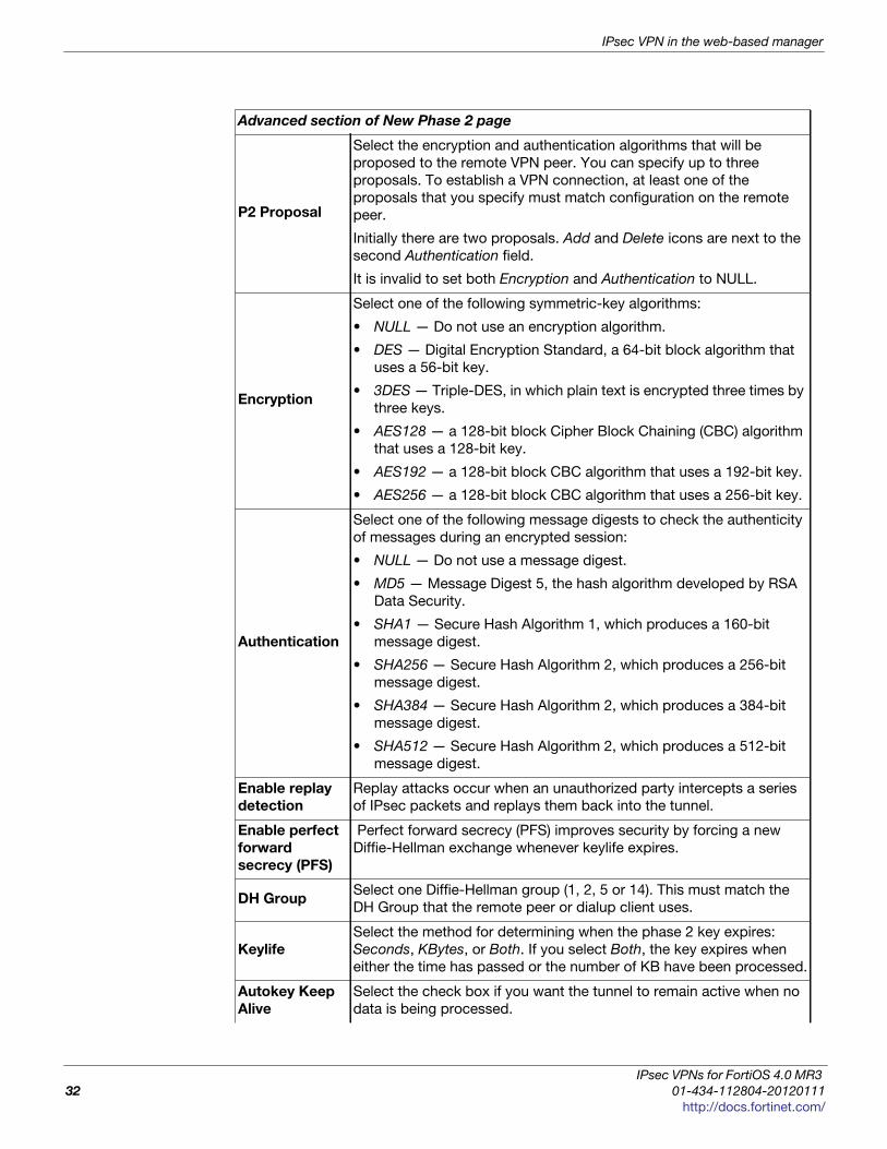
IPsec VPN in the web-based manager
Advanced section of New Phase 2 page
P2 Proposal
Select the encryption and authentication algorithms that will be
proposed to the remote VPN peer. You can specify up to three
proposals. To establish a VPN connection, at least one of the
proposals that you specify must match configuration on the remote
peer.
Initially there are two proposals. Add and Delete icons are next to the
second Authentication field.
It is invalid to set both Encryption and Authentication to NULL.
Encryption
Select one of the following symmetric-key algorithms:
• NULL — Do not use an encryption algorithm.
• DES — Digital Encryption Standard, a 64-bit block algorithm that
uses a 56-bit key.
• 3DES — Triple-DES, in which plain text is encrypted three times by
three keys.
• AES128 — a 128-bit block Cipher Block Chaining (CBC) algorithm
that uses a 128-bit key.
• AES192 — a 128-bit block CBC algorithm that uses a 192-bit key.
• AES256 — a 128-bit block CBC algorithm that uses a 256-bit key.
Authentication
Select one of the following message digests to check the authenticity
of messages during an encrypted session:
• NULL — Do not use a message digest.
• MD5 — Message Digest 5, the hash algorithm developed by RSA
Data Security.
• SHA1 — Secure Hash Algorithm 1, which produces a 160-bit
message digest.
• SHA256 — Secure Hash Algorithm 2, which produces a 256-bit
message digest.
• SHA384 — Secure Hash Algorithm 2, which produces a 384-bit
message digest.
• SHA512 — Secure Hash Algorithm 2, which produces a 512-bit
message digest.
Enable replay
detection
Replay attacks occur when an unauthorized party intercepts a series
of IPsec packets and replays them back into the tunnel.
Enable perfect
forward
secrecy (PFS)
Perfect forward secrecy (PFS) improves security by forcing a new
Diffie-Hellman exchange whenever keylife expires.
DH GroupSelect one Diffie-Hellman group (1, 2, 5 or 14). This must match the
DH Group that the remote peer or dialup client uses.
Keylife
Select the method for determining when the phase 2 key expires:
Seconds, KBytes, or Both. If you select Both, the key expires when
either the time has passed or the number of KB have been processed.
Autokey Keep
Alive
Select the check box if you want the tunnel to remain active when no
data is being processed.
IPsec VPNs for FortiOS 4.0 MR3
32 01-434-112804-20120111
http://docs.fortinet.com/
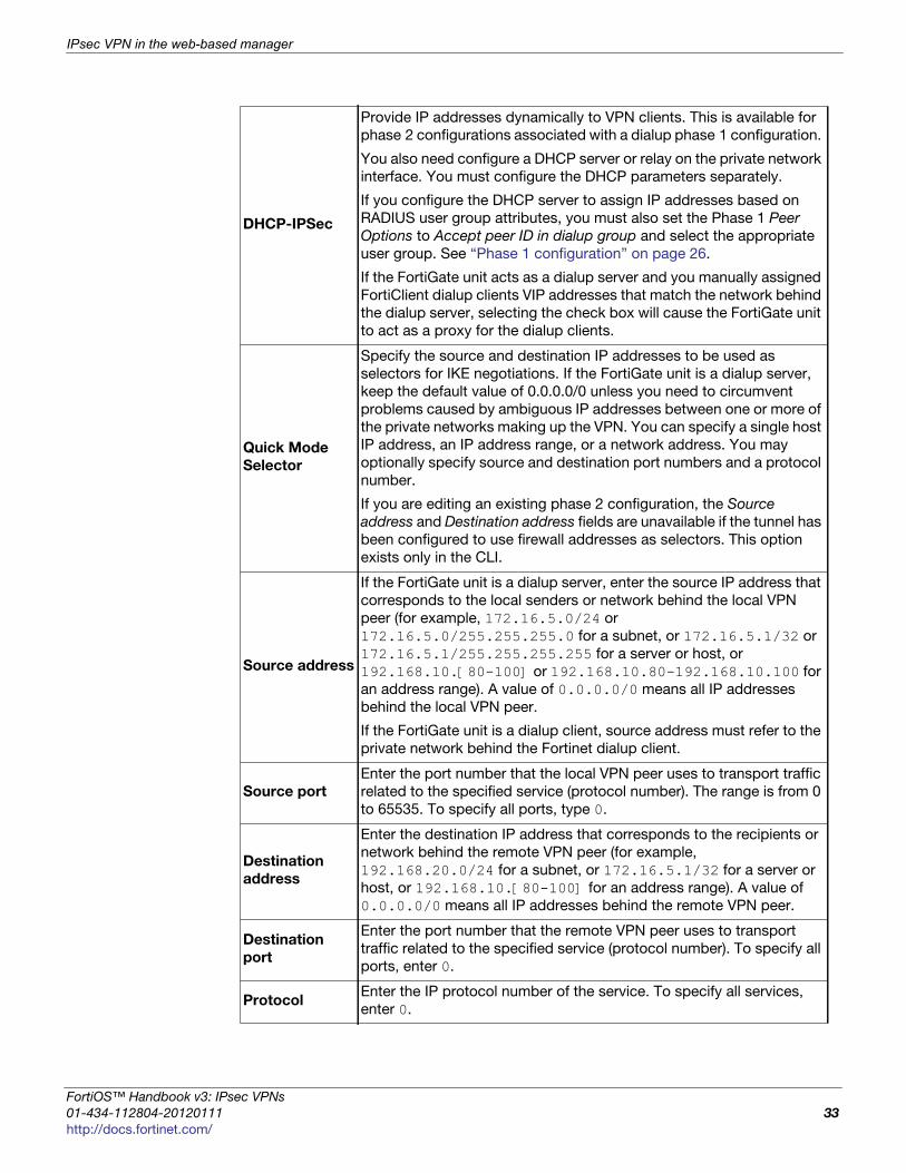
IPsec VPN in the web-based manager
F
0
h
DHCP-IPSec
Provide IP addresses dynamically to VPN clients. This is available for
phase 2 configurations associated with a dialup phase 1 configuration.
You also need configure a DHCP server or relay on the private network
interface. You must configure the DHCP parameters separately.
If you configure the DHCP server to assign IP addresses based on
RADIUS user group attributes, you must also set the Phase 1 Peer
Options to Accept peer ID in dialup group and select the appropriate
user group. See “Phase 1 configuration” on page 26.
If the FortiGate unit acts as a dialup server and you manually assigned
FortiClient dialup clients VIP addresses that match the network behind
the dialup server, selecting the check box will cause the FortiGate unit
to act as a proxy for the dialup clients.
Quick Mode
Selector
Specify the source and destination IP addresses to be used as
selectors for IKE negotiations. If the FortiGate unit is a dialup server,
keep the default value of 0.0.0.0/0 unless you need to circumvent
problems caused by ambiguous IP addresses between one or more of
the private networks making up the VPN. You can specify a single host
IP address, an IP address range, or a network address. You may
optionally specify source and destination port numbers and a protocol
number.
If you are editing an existing phase 2 configuration, the Source
address and Destination address fields are unavailable if the tunnel has
been configured to use firewall addresses as selectors. This option
exists only in the CLI.
Source address
If the FortiGate unit is a dialup server, enter the source IP address that
corresponds to the local senders or network behind the local VPN
peer (for example, 172.16.5.0/24 or
172.16.5.0/255.255.255.0 for a subnet, or 172.16.5.1/32 or
172.16.5.1/255.255.255.255 for a server or host, or
192.168.10.[80-100] or 192.168.10.80-192.168.10.100 for
an address range). A value of 0.0.0.0/0 means all IP addresses
behind the local VPN peer.
If the FortiGate unit is a dialup client, source address must refer to the
private network behind the Fortinet dialup client.
Source port
Enter the port number that the local VPN peer uses to transport traffic
related to the specified service (protocol number). The range is from 0
to 65535. To specify all ports, type 0.
Destination
address
Enter the destination IP address that corresponds to the recipients or
network behind the remote VPN peer (for example,
192.168.20.0/24 for a subnet, or 172.16.5.1/32 for a server or
host, or 192.168.10.[80-100] for an address range). A value of
0.0.0.0/0 means all IP addresses behind the remote VPN peer.
Destination
port
Enter the port number that the remote VPN peer uses to transport
traffic related to the specified service (protocol number). To specify all
ports, enter 0.
ProtocolEnter the IP protocol number of the service. To specify all services,
enter 0.
ortiOS™ Handbook v3: IPsec VPNs
1-434-112804-20120111 33ttp://docs.fortinet.com/
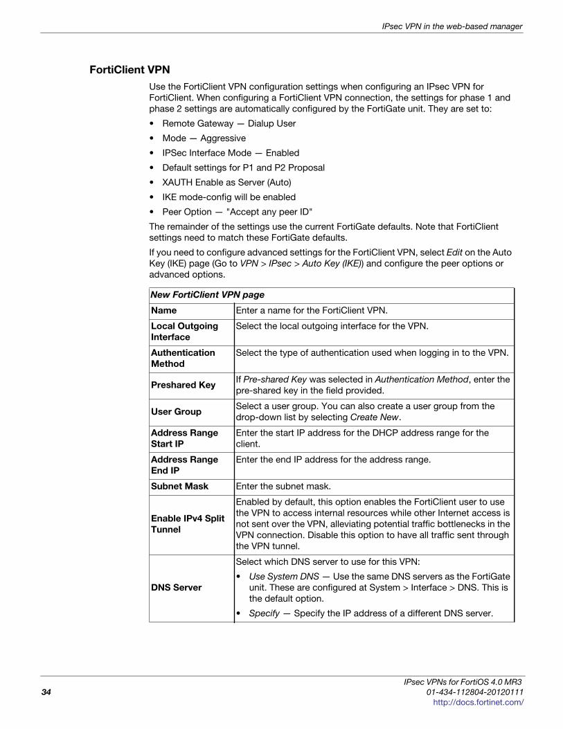
IPsec VPN in the web-based manager
FortiClient VPN
Use the FortiClient VPN configuration settings when configuring an IPsec VPN for
FortiClient. When configuring a FortiClient VPN connection, the settings for phase 1 and
phase 2 settings are automatically configured by the FortiGate unit. They are set to:
• Remote Gateway — Dialup User
• Mode — Aggressive
• IPSec Interface Mode — Enabled
• Default settings for P1 and P2 Proposal
• XAUTH Enable as Server (Auto)
• IKE mode-config will be enabled
• Peer Option — "Accept any peer ID"
The remainder of the settings use the current FortiGate defaults. Note that FortiClient
settings need to match these FortiGate defaults.
If you need to configure advanced settings for the FortiClient VPN, select Edit on the Auto
Key (IKE) page (Go to VPN > IPsec > Auto Key (IKE)) and configure the peer options or
advanced options.
New FortiClient VPN page
Name Enter a name for the FortiClient VPN.
Local Outgoing
Interface
Select the local outgoing interface for the VPN.
Authentication
Method
Select the type of authentication used when logging in to the VPN.
Preshared KeyIf Pre-shared Key was selected in Authentication Method, enter the
pre-shared key in the field provided.
User GroupSelect a user group. You can also create a user group from the
drop-down list by selecting Create New.
Address Range
Start IP
Enter the start IP address for the DHCP address range for the
client.
Address Range
End IP
Enter the end IP address for the address range.
Subnet Mask Enter the subnet mask.
Enable IPv4 Split
Tunnel
Enabled by default, this option enables the FortiClient user to use
the VPN to access internal resources while other Internet access is
not sent over the VPN, alleviating potential traffic bottlenecks in the
VPN connection. Disable this option to have all traffic sent through
the VPN tunnel.
DNS Server
Select which DNS server to use for this VPN:
• Use System DNS — Use the same DNS servers as the FortiGate
unit. These are configured at System > Interface > DNS. This is
the default option.
• Specify — Specify the IP address of a different DNS server.
IPsec VPNs for FortiOS 4.0 MR3
34 01-434-112804-20120111
http://docs.fortinet.com/
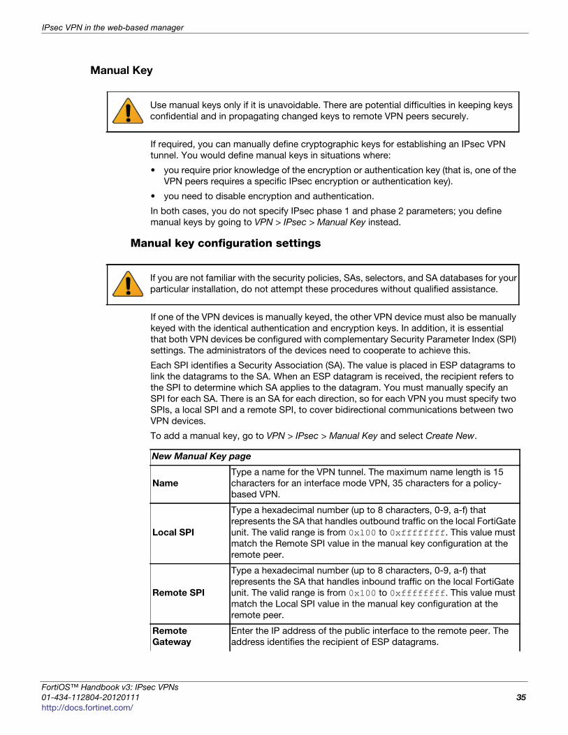
IPsec VPN in the web-based manager
F
0
h
Manual Key
If required, you can manually define cryptographic keys for establishing an IPsec VPN
tunnel. You would define manual keys in situations where:
• you require prior knowledge of the encryption or authentication key (that is, one of the
VPN peers requires a specific IPsec encryption or authentication key).
• you need to disable encryption and authentication.
In both cases, you do not specify IPsec phase 1 and phase 2 parameters; you define
manual keys by going to VPN > IPsec > Manual Key instead.
Manual key configuration settings
If one of the VPN devices is manually keyed, the other VPN device must also be manually
keyed with the identical authentication and encryption keys. In addition, it is essential
that both VPN devices be configured with complementary Security Parameter Index (SPI)
settings. The administrators of the devices need to cooperate to achieve this.
Each SPI identifies a Security Association (SA). The value is placed in ESP datagrams to
link the datagrams to the SA. When an ESP datagram is received, the recipient refers to
the SPI to determine which SA applies to the datagram. You must manually specify an
SPI for each SA. There is an SA for each direction, so for each VPN you must specify two
SPIs, a local SPI and a remote SPI, to cover bidirectional communications between two
VPN devices.
To add a manual key, go to VPN > IPsec > Manual Key and select Create New.
Use manual keys only if it is unavoidable. There are potential difficulties in keeping keys
confidential and in propagating changed keys to remote VPN peers securely.
If you are not familiar with the security policies, SAs, selectors, and SA databases for your
particular installation, do not attempt these procedures without qualified assistance.
New Manual Key page
Name
Type a name for the VPN tunnel. The maximum name length is 15
characters for an interface mode VPN, 35 characters for a policy-
based VPN.
Local SPI
Type a hexadecimal number (up to 8 characters, 0-9, a-f) that
represents the SA that handles outbound traffic on the local FortiGate
unit. The valid range is from 0x100 to 0xffffffff. This value must
match the Remote SPI value in the manual key configuration at the
remote peer.
Remote SPI
Type a hexadecimal number (up to 8 characters, 0-9, a-f) that
represents the SA that handles inbound traffic on the local FortiGate
unit. The valid range is from 0x100 to 0xffffffff. This value must
match the Local SPI value in the manual key configuration at the
remote peer.
Remote
Gateway
Enter the IP address of the public interface to the remote peer. The
address identifies the recipient of ESP datagrams.
ortiOS™ Handbook v3: IPsec VPNs
1-434-112804-20120111 35ttp://docs.fortinet.com/
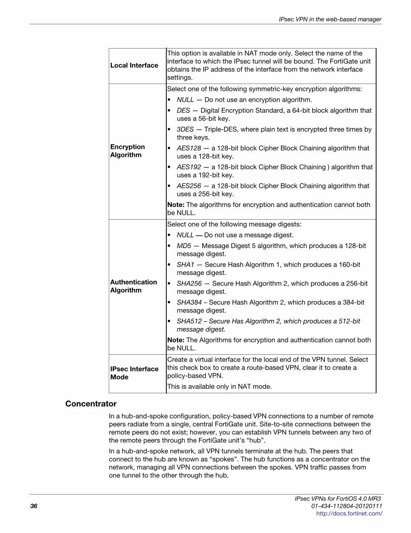
IPsec VPN in the web-based manager
Concentrator
In a hub-and-spoke configuration, policy-based VPN connections to a number of remote
peers radiate from a single, central FortiGate unit. Site-to-site connections between the
remote peers do not exist; however, you can establish VPN tunnels between any two of
the remote peers through the FortiGate unit’s “hub”.
In a hub-and-spoke network, all VPN tunnels terminate at the hub. The peers that
connect to the hub are known as “spokes”. The hub functions as a concentrator on the
network, managing all VPN connections between the spokes. VPN traffic passes from
one tunnel to the other through the hub.
Local Interface
This option is available in NAT mode only. Select the name of the
interface to which the IPsec tunnel will be bound. The FortiGate unit
obtains the IP address of the interface from the network interface
settings.
Encryption
Algorithm
Select one of the following symmetric-key encryption algorithms:
• NULL — Do not use an encryption algorithm.
• DES — Digital Encryption Standard, a 64-bit block algorithm that
uses a 56-bit key.
• 3DES — Triple-DES, where plain text is encrypted three times by
three keys.
• AES128 — a 128-bit block Cipher Block Chaining algorithm that
uses a 128-bit key.
• AES192 — a 128-bit block Cipher Block Chaining ) algorithm that
uses a 192-bit key.
• AES256 — a 128-bit block Cipher Block Chaining algorithm that
uses a 256-bit key.
Note: The algorithms for encryption and authentication cannot both
be NULL.
Authentication
Algorithm
Select one of the following message digests:
• NULL –– Do not use a message digest.
• MD5 — Message Digest 5 algorithm, which produces a 128-bit
message digest.
• SHA1 — Secure Hash Algorithm 1, which produces a 160-bit
message digest.
• SHA256 — Secure Hash Algorithm 2, which produces a 256-bit
message digest.
• SHA384 – Secure Hash Algorithm 2, which produces a 384-bit
message digest.
• SHA512 – Secure Has Algorithm 2, which produces a 512-bit
message digest.
Note: The Algorithms for encryption and authentication cannot both
be NULL.
IPsec Interface
Mode
Create a virtual interface for the local end of the VPN tunnel. Select
this check box to create a route-based VPN, clear it to create a
policy-based VPN.
This is available only in NAT mode.
IPsec VPNs for FortiOS 4.0 MR3
36 01-434-112804-20120111
http://docs.fortinet.com/

IPsec VPN in the web-based manager IPsec Monitor
F
0
h
You define a concentrator to include spokes in the hub-and-spoke configuration. You
create the concentrator in VPN > IPSec > Concentrator and select Create New. A
concentrator configuration specifies which spokes to include in an IPsec hub-and-spoke
configuration.
IPsec Monitor
You can use the IPsec Monitor to view activity on IPsec VPN tunnels and start or stop
those tunnels. The display provides a list of addresses, proxy IDs, and timeout
information for all active tunnels, including tunnel mode and route-based (interface mode)
tunnels.
To view the IPsec monitor, go to VPN > Monitor > IPsec Monitor.
For dialup VPNs, the list provides status information about the VPN tunnels established
by dialup clients, and their IP addresses.
For static IP or dynamic DNS VPNs, the list provides status and IP addressing
information about VPN tunnels, active or not, to remote peers that have static IP
addresses or domain names. You can also start and stop individual tunnels from the list.
New VPN Concentrator page
Concentrator
Name
Type a name for the concentrator.
Available TunnelsA list of defined IPsec VPN tunnels. Select a tunnel from the list and
then select the right arrow.
Members
A list of tunnels that are members of the concentrator. To remove a
tunnel from the concentrator, select the tunnel and select the left
arrow.
ortiOS™ Handbook v3: IPsec VPNs
1-434-112804-20120111 37ttp://docs.fortinet.com/

IPsec Monitor IPsec VPN in the web-based manager
IPsec VPNs for FortiOS 4.0 MR3
38 01-434-112804-20120111
http://docs.fortinet.com/
F o r t i O S H a n d b o o k
F
0
h
Auto Key phase 1 parameters This chapter provides detailed step-by-step procedures for configuring a FortiGate unit
to accept a connection from a remote peer or dialup client. The phase 1 parameters
identify the remote peer or clients and support authentication through preshared keys or
digital certificates. You can increase access security further using peer identifiers,
certificate distinguished names, group names, or the FortiGate extended authentication
(XAuth) option for authentication purposes.
For more information on phase 1 parameters in the web-based manager, see “Phase 1
configuration” on page 26.
The following topics are included in this section:
• Overview
• Defining the tunnel ends
• Choosing main mode or aggressive mode
• Authenticating the FortiGate unit
• Authenticating remote peers and clients
• Defining IKE negotiation parameters
• Using XAuth authentication
Overview
To configure IPsec phase 1 settings, go to VPN > IPsec > Auto Key (IKE) and select
Create Phase 1. IPsec phase 1 settings define:
• the remote and local ends of the IPsec tunnel
• if phase 1 parameters are exchanged in multiple rounds with encrypted authentication
information (main mode) or in a single message with authentication information that is
not encrypted (aggressive mode)
• if a preshared key or digital certificates will be used to authenticate the FortiGate unit
to the VPN peer or dialup client
• if the VPN peer or dialup client is required to authenticate to the FortiGate unit. A
remote peer or dialup client can authenticate by peer ID or, if the FortiGate unit
authenticates by certificate, it can authenticate by peer certificate.
• the IKE negotiation proposals for encryption and authentication
• optional XAuth authentication, which requires the remote user to enter a user name
and password. A FortiGate VPN server can act as an XAuth server to authenticate
dialup users. A FortiGate unit that is a dialup client can also be configured as an XAuth
client to authenticate itself to the VPN server.
For all the phase 1 web-based manager fields, see “Phase 1 configuration” on page 26.
The information and procedures in this section do not apply to VPN peers that perform
negotiations using manual keys. Refer to “Manual-key configurations” on page 183
instead.
ortiOS™ Handbook v3: IPsec VPNs
1-434-112804-20120111 39ttp://docs.fortinet.com/

Defining the tunnel ends Auto Key phase 1 parameters
Defining the tunnel ends
To begin defining the phase 1 configuration, go to VPN > IPsec > Auto Key (IKE) and
select Create Phase 1. Enter a descriptive name for the VPN tunnel. This is particularly
important if you will create several tunnels.
The phase 1 configuration mainly defines the ends of the IPsec tunnel. The remote end is
the remote gateway with which the FortiGate unit exchanges IPsec packets. The local
end is the FortiGate interface that sends and receives IPsec packets.
The remote gateway can be:
• a static IP address
• a domain name with a dynamic IP address
• a dialup client
A statically addressed remote gateway is the simplest to configure. You specify the IP
address. Unless restricted in the security policy, either the remote peer or a peer on the
network behind the FortiGate unit can bring up the tunnel.
If the remote peer has a domain name and subscribes to a dynamic DNS service, you
need to specify only the domain name. The FortiGate unit performs a DNS query to
determine the appropriate IP address. Unless restricted in the security policy, either the
remote peer or a peer on the network behind the FortiGate unit can bring up the tunnel.
If the remote peer is a dialup client, only the dialup client can bring up the tunnel. The IP
address of the client is not known until it connects to the FortiGate unit. This
configuration is a typical way to provide a VPN for client PCs running VPN client software
such as the FortiClient Endpoint Security application.
The local end of the VPN tunnel, the Local Interface, is the FortiGate interface that sends
and receives the IPsec packets. This is usually the public interface of the FortiGate unit
that is connected to the Internet. Packets from this interface pass to the private network
through a security policy.
By default, the local VPN gateway is the IP address of the selected Local Interface. If you
are configuring an interface mode VPN, you can optionally use a secondary IP address of
the Local Interface as the local gateway.
Choosing main mode or aggressive mode
The FortiGate unit and the remote peer or dialup client exchange phase 1 parameters in
either Main mode or Aggressive mode. This choice does not apply if you use IKE
version 2, which is available only for route-based configurations.
• In Main mode, the phase 1 parameters are exchanged in multiple rounds with
encrypted authentication information
If you want to control how the IKE negotiation process controls traffic when there is no
traffic, as well as the length of time the unit waits for negotiations to occur, use the
negotiation-timeout and auto-negotiation commands in the CLI.
The local Interface for a Phase 1 cannot not be a loopback interface. By design, the IPSec
tunnel will not be established if this happens.
IPsec VPNs for FortiOS 4.0 MR3
40 01-434-112804-20120111
http://docs.fortinet.com/
Auto Key phase 1 parameters Choosing the IKE version
F
0
h
• In Aggressive mode, the phase 1 parameters are exchanged in single message with
authentication information that is not encrypted.
Although Main mode is more secure, you must select Aggressive mode if there is more
than one dialup phase 1 configuration for the interface IP address, and the remote VPN
peer or client is authenticated using an identifier local ID). Descriptions of the peer
options in this guide indicate whether Main or Aggressive mode is required.
Choosing the IKE version
If you create a route-based VPN, you have the option of selecting IKE version 2.
Otherwise, IKE version 1 is used.
IKEv2, defined in RFC 4306, simplifies the negotiation process that creates the security
association (SA).
If you select IKEv2:
• There is no choice in Phase 1 of Aggressive or Main mode.
• FortiOS does not support Peer Options or Local ID.
• Extended Authentication (XAUTH) is not available.
• You can select only one DH Group.
Authenticating the FortiGate unit
The FortiGate unit can authenticate itself to remote peers or dialup clients using either a
pre-shared key or an RSA Signature (certificate).
Authenticating the FortiGate unit with digital certificates
To authenticate the FortiGate unit using digital certificates, you must have the required
certificates installed on the remote peer and on the FortiGate unit. The signed server
certificate on one peer is validated by the presence of the root certificate installed on the
other peer. If you use certificates to authenticate the FortiGate unit, you can also require
the remote peers or dialup clients to authenticate using certificates.
For more information about obtaining and installing certificates, see the FortiOS User
Authentication guide.
To authenticate the FortiGate unit using digital certificates
1 Go to VPN > IPsec > Auto Key (IKE).
2 Create a new phase 1 configuration or edit an existing phase 1 configuration.
3 Include appropriate entries as follows:
Name
Enter a name that reflects the origination of the remote
connection. For interface mode, the name can be up to 15
characters long.
Remote Gateway
Select the nature of the remote connection.
Each option changes the available fields you must
configure. For more information, see “Defining the tunnel
ends” on page 40.
ortiOS™ Handbook v3: IPsec VPNs
1-434-112804-20120111 41ttp://docs.fortinet.com/

Authenticating the FortiGate unit Auto Key phase 1 parameters
4 If you are configuring authentication parameters for a dialup user group, optionally
define extended authentication (XAuth) parameters in the Advanced section. See
“Using the FortiGate unit as an XAuth server” on page 54.
5 Select OK.
Authenticating the FortiGate unit with a pre-shared key
The simplest way to authenticate a FortiGate unit to its remote peers or dialup clients is
by means of a pre-shared key. This is less secure than using certificates, especially if it is
used alone, without requiring peer IDs or extended authentication (XAuth). Also, you need
to have a secure way to distribute the pre-shared key to the peers.
Local Interface
Select the interface that is the local end of the IPsec tunnel.
For more information, see “Defining the tunnel ends” on
page 40.
This interface cannot be a loopback interface.
Mode
Select amode. It is easier to use aggressive mode.
• In Main mode, parameters are exchanged in multiple
encrypted rounds.
• In Aggressive mode, parameters are exchanged in a
single unencrypted message.
Aggressive mode must be used when the remote VPN peer
or client has a dynamic IP address, or the remote VPN peer
or client will be authenticated using an identifier (local ID).
For more information, see “Choosing main mode or
aggressive mode” on page 40.
Authentication
Method
Select RSA Signature.
Certificate Name
Select the name of the server certificate that the FortiGate
unit will use to authenticate itself to the remote peer or
dialup client during phase 1 negotiations.
You must obtain and load the required server certificate
before this selection. See the FortiOS User Authentication
guide. If you have not loaded any certificates, use the
certificate named Fortinet_Factory.
Peer Options
Peer options define the authentication requirements for
remote peers or dialup clients. They are not for your
FortiGate unit itself.
See “Authenticating remote peers and clients” on page 44.
Advanced
You can use the default settings for most phase 1
configurations. Changes are required only if your network
requires them. These settings includes IKE version, DNS
server, P1 proposal encryption and authentication settings,
and XAuth settings. See “Defining IKE negotiation
parameters” on page 49.
IPsec VPNs for FortiOS 4.0 MR3
42 01-434-112804-20120111
http://docs.fortinet.com/
Auto Key phase 1 parameters Authenticating the FortiGate unit
F
0
h
If you use pre-shared key authentication alone, all remote peers and dialup clients must
be configured with the same pre-shared key. Optionally, you can configure remote peers
and dialup clients with unique pre-shared keys. On the FortiGate unit, these are
configured in user accounts, not in the phase_1 settings. For more information, see
“Enabling VPN access with user accounts and pre-shared keys” on page 47.
The pre-shared key must contain at least 6 printable characters and best practices
dictate that it be known only to network administrators. For optimum protection against
currently known attacks, the key must consist of a minimum of 16 randomly chosen
alphanumeric characters.
If you authenticate the FortiGate unit using a pre-shared key, you can require remote
peers or dialup clients to authenticate using peer IDs, but not client certificates.
To authenticate the FortiGate unit with a pre-shared key
1 Go to VPN > IPsec > Auto Key (IKE).
2 Create a new phase 1 configuration or edit an existing phase 1 configuration.
3 Include appropriate entries as follows:
NameEnter a name that reflects the origination of the remote
connection.
Remote GatewaySelect the nature of the remote connection. For more
information, see “Defining the tunnel ends” on page 40.
Local Interface
Select the interface that is the local end of the IPsec
tunnel. For more information, see “Defining the tunnel
ends” on page 40.
Mode
Select Main or Aggressive mode.
• In Main mode, the phase 1 parameters are exchanged
in multiple rounds with encrypted authentication
information.
• In Aggressive mode, the phase 1 parameters are
exchanged in single message with authentication
information that is not encrypted.
When the remote VPN peer or client has a dynamic IP
address, or the remote VPN peer or client will be
authenticated using an identifier (local ID), you must select
Aggressive mode if there is more than one dialup phase 1
configuration for the interface IP address.
For more information, see “Choosing main mode or
aggressive mode” on page 40.
Authentication Method Select Pre-shared Key.
Pre-shared Key
Enter the preshared key that the FortiGate unit will use to
authenticate itself to the remote peer or dialup client
during phase 1 negotiations. You must define the same
value at the remote peer or client. The key must contain at
least 6 printable characters and best practices dictate that
it only be known by network administrators. For optimum
protection against currently known attacks, the key must
consist of a minimum of 16 randomly chosen
alphanumeric characters.
ortiOS™ Handbook v3: IPsec VPNs
1-434-112804-20120111 43ttp://docs.fortinet.com/
Authenticating remote peers and clients Auto Key phase 1 parameters
4 If you are configuring authentication parameters for a dialup user group, optionally
define extended authentication (XAuth) parameters. See “Using the FortiGate unit as
an XAuth server” on page 54.
5 Select OK.
Authenticating remote peers and clients
Certificates or pre-shared keys restrict who can access the VPN tunnel, but they do not
identify or authenticate the remote peers or dialup clients. You have the following options
for authentication:
For authentication of users of the remote peer or dialup client device, see “Using XAuth
authentication” on page 54.
Enabling VPN access for specific certificate holders
When a VPN peer or dialup client is configured to authenticate using digital certificates, it
sends the DN of its certificate to the FortiGate unit. This DN can be used to allow VPN
access for the certificate holder. That is, a FortiGate unit can be configured to deny
connections to all remote peers and dialup clients except the one having the
specified DN.
Before you beginThe following procedures assume that you already have an existing phase 1 configuration
(see “Authenticating the FortiGate unit with digital certificates” on page 41). Follow the
procedures below to add certificate-based authentication parameters to the existing
configuration.
Peer options
Peer options define the authentication requirements for
remote peers or dialup clients, not for the FortiGate unit
itself. You can require the use of peer IDs, but not client
certificates. For more information, see “Authenticating
remote peers and clients” on page 44.
Advanced
You can retain the default settings unless changes are
needed to meet your specific requirements. See “Defining
IKE negotiation parameters” on page 49.
Table 3: Methods of authenticating remote VPN peers
Certificates or
Pre-shared
key
Local
ID
User
account
pre-shared
keys
Reference
Certificates See “Enabling VPN access for specific
certificate holders” on page 44
Either X See “Enabling VPN access by peer identifier”
on page 46
Pre-shared key X See “Enabling VPN access with user
accounts and pre-shared keys” on page 47
Pre-shared key X X See “Enabling VPN access with user
accounts and pre-shared keys” on page 47
IPsec VPNs for FortiOS 4.0 MR3
44 01-434-112804-20120111
http://docs.fortinet.com/
Auto Key phase 1 parameters Authenticating remote peers and clients
F
0
h
Before you begin, you must obtain the certificate DN of the remote peer or dialup client. If
you are using the FortiClient application as a dialup client, refer to FortiClient online Help
for information about how to view the certificate DN. To view the certificate DN of a
FortiGate unit, see “To view server certificate information and obtain the local DN” on
page 45.
Use the config user peer CLI command to load the DN value into the FortiGate
configuration. For example, if a remote VPN peer uses server certificates issued by your
own organization, you would enter information similar to the following:
config user peeredit DN_FG1000set cn 192.168.2.160set cn-type ipv4
end
The value that you specify to identify the entry (for example, DN_FG1000) is displayed in
the Accept this peer certificate only list in the IPsec phase 1 configuration when you
return to the web-based manager.
If the remote VPN peer has a CA-issued certificate to support a higher level of credibility,
you would enter information similar to the following:
config user peeredit CA_FG1000set ca CA_Cert_1set subject FG1000_at_site1
end
The value that you specify to identify the entry (for example, CA_FG1000) is displayed in
the Accept this peer certificate only list in the IPsec phase 1 configuration when you
return to the web-based manager. For more information about these CLI commands, see
the “user” chapter of the FortiGate CLI Reference.
A group of certificate holders can be created based on existing user accounts for dialup
clients. To create the user accounts for dialup clients, see the “User” chapter of the
FortiGate Administration Guide. To create the certificate group afterward, use the config user peergrp CLI command. See the “user” chapter of the FortiGate CLI Reference.
To view server certificate information and obtain the local DN
1 Go to System > Certificates > Local Certificates.
2 Note the CN value in the Subject field (for example, CN = 172.16.10.125,
CN = [email protected], or CN = www.example.com).
To view CA root certificate information and obtain the CA certificate name
1 Go to System > Certificates > CA Certificates.
2 Note the value in the Name column (for example, CA_Cert_1).
Configuring certificate authentication for a VPNWith peer certificates loaded, peer users and peer groups defined, you can configure
your VPN to authenticate users by certificate.
To enable access for a specific certificate holder or a group of certificate holders
1 At the FortiGate VPN server, go to VPN > IPsec > Auto Key (IKE).
2 In the list of defined configurations, select the phase 1 configuration and edit it.
3 From the Authentication Method list, select RSA Signature.
ortiOS™ Handbook v3: IPsec VPNs
1-434-112804-20120111 45ttp://docs.fortinet.com/
Authenticating remote peers and clients Auto Key phase 1 parameters
4 From the Certificate Name list, select the name of the server certificate that the
FortiGate unit will use to authenticate itself to the remote peer or dialup client
5 Under Peer Options, select one of these options:
• To accept a specific certificate holder, select Accept this peer certificate only and
select the name of the certificate that belongs to the remote peer or dialup client.
The certificate DN must be added to the FortiGate configuration through CLI
commands before it can be selected here. See “Before you begin” on page 44.
• To accept dialup clients who are members of a certificate group, select Accept this
peer certificate group only and select the name of the group. The group must be
added to the FortiGate configuration through CLI commands before it can be
selected here. See “Before you begin” on page 44.
6 If you want the FortiGate VPN server to supply the DN of a local server certificate for
authentication purposes, select Advanced and then from the Local ID list, select the
DN of the certificate that the FortiGate VPN server is to use.
7 Select OK.
Enabling VPN access by peer identifier
Whether you use certificates or pre-shared keys to authenticate the FortiGate unit, you
can require that remote peers or clients have a particular peer ID. This adds another piece
of information that is required to gain access to the VPN. More than one
FortiGate/FortiClient dialup client may connect through the same VPN tunnel when the
dialup clients share a preshared key and assume the same identifier.
A peer ID, also called local ID, can be up to 63 characters long containing standard
regular expression characters. Local ID is set in phase1 Aggressive Mode configuration.
You cannot require a peer ID for a remote peer or client that uses a pre-shared key and
has a static IP address.
To authenticate remote peers or dialup clients using one peer ID
1 At the FortiGate VPN server, go to VPN > IPsec > Auto Key (IKE).
2 In the list, select a phase 1 configuration and edit its parameters.
3 Select Aggressive mode in any of the following cases:
• the FortiGate VPN server authenticates a FortiGate dialup client that uses a
dedicated tunnel
• a FortiGate unit has a dynamic IP address and subscribes to a dynamic DNS
service
• FortiGate/FortiClient dialup clients sharing the same preshared key and local ID
connect through the same VPN tunnel
4 Select Accept this peer ID and type the identifier into the corresponding field.
5 Select OK.
To assign an identifier (local ID) to a FortiGate unit
Use this procedure to assign a peer ID to a FortiGate unit that acts as a remote peer or
dialup client.
1 Go to VPN > IPsec > Auto Key (IKE).
2 In the list, select a phase 1 configuration and edit its parameters.
3 Select Advanced.
4 In the Local ID field, type the identifier that the FortiGate unit will use to identify itself.
IPsec VPNs for FortiOS 4.0 MR3
46 01-434-112804-20120111
http://docs.fortinet.com/

Auto Key phase 1 parameters Authenticating remote peers and clients
F
0
h
5 Set Mode to Aggressive if any of the following conditions apply:
• The FortiGate unit is a dialup client that will use a unique ID to connect to a
FortiGate dialup server through a dedicated tunnel.
• The FortiGate unit has a dynamic IP address, subscribes to a dynamic DNS
service, and will use a unique ID to connect to the remote VPN peer through a
dedicated tunnel.
• The FortiGate unit is a dialup client that shares the specified ID with multiple dialup
clients to connect to a FortiGate dialup server through the same tunnel.
6 Select OK.
To configure the FortiClient application
Follow this procedure to add a peer ID to an existing FortiClient configuration:
1 Start the FortiClient application.
2 Go to VPN > Connections, select the existing configuration.
3 Select Advanced > Edit > Advanced.
4 Under Policy, select Config.
5 In the Local ID field, type the identifier that will be shared by all dialup clients. This
value must match the Accept this peer ID value that you specified previously in the
phase 1 gateway configuration on the FortiGate unit.
6 Select OK to close all dialog boxes.
7 Configure all dialup clients the same way using the same preshared key and local ID.
Enabling VPN access with user accounts and pre-shared keys
You can permit access only to remote peers or dialup clients that have pre-shared keys
and/or peer IDs configured in user accounts on the FortiGate unit.
If you want two VPN peers (or a FortiGate unit and a dialup client) to accept reciprocal
connections based on peer IDs, you must enable the exchange of their identifiers when
you define the phase 1 parameters.
The following procedures assume that you already have an existing phase 1 configuration
(see “Authenticating the FortiGate unit with digital certificates” on page 41). Follow the
procedures below to add ID checking to the existing configuration.
Before you begin, you must obtain the identifier (local ID) of the remote peer or dialup
client. If you are using the FortiClient Endpoint Security application as a dialup client,
refer to the Authenticating FortiClient Dialup Clients Technical Note to view or assign an
identifier. To assign an identifier to a FortiGate dialup client or a FortiGate unit that has a
dynamic IP address and subscribes to a dynamic DNS service, see “To assign an
identifier (local ID) to a FortiGate unit” on page 46.
If required, a dialup user group can be created from existing user accounts for dialup
clients. To create the user accounts and user groups, see the User Authentication Guide.
The following procedure supports FortiGate/FortiClient dialup clients that use unique
preshared keys and/or peer IDs. The client must have an account on the FortiGate unit
and be a member of the dialup user group.
The dialup user group must be added to the FortiGate configuration before it can be
selected. For more information, see the User Authentication Guide.
The FortiGate dialup server compares the local ID that you specify at each dialup client to
the FortiGate user-account user name. The dialup-client preshared key is compared to a
FortiGate user-account password.
ortiOS™ Handbook v3: IPsec VPNs
1-434-112804-20120111 47ttp://docs.fortinet.com/
Authenticating remote peers and clients Auto Key phase 1 parameters
To authenticate dialup clients using unique preshared keys and/or peer IDs
1 At the FortiGate VPN server, go to VPN > IPsec > Auto Key (IKE).
2 In the list, select the Edit icon of a phase 1 configuration to edit its parameters.
3 If the clients have unique peer IDs, set Mode to Aggressive.
4 Clear the Pre-shared Key field.
The user account password will be used as the preshared key.
5 Select Accept peer ID in dialup group and then select the group name from the list of
user groups.
6 Select OK.
Follow this procedure to add a unique pre-shared key and unique peer ID to an existing
FortiClient configuration.
To configure FortiClient - pre-shared key and peer ID
1 Start the FortiClient Endpoint Security application.
2 Go to VPN > Connections, select the existing configuration.
3 Select Advanced > Edit.
4 In the Preshared Key field, type the FortiGate password that belongs to the dialup
client (for example, 1234546).
The user account password will be used as the preshared key.
5 Select Advanced.
6 Under Policy, select Config.
7 In the Local ID field, type the FortiGate user name that you assigned previously to the
dialup client (for example, FortiC1ient1).
8 Select OK to close all dialog boxes.
Configure all FortiClient dialup clients this way using unique preshared keys and local
IDs.
Follow this procedure to add a unique pre-shared key to an existing FortiClient
configuration.
To configure FortiClient - preshared key only
1 Start the FortiClient Endpoint Security application.
2 Go to VPN > Connections, select the existing configuration
3 Select Advanced > Edit.
4 In the Preshared Key field, type the user name, followed by a “+” sign, followed by the
password that you specified previously in the user account settings on the FortiGate
unit (for example, FC2+1FG6LK)
5 Select OK to close all dialog boxes.
Configure all the FortiClient dialup clients this way using their unique peer ID and
pre-shared key values.
IPsec VPNs for FortiOS 4.0 MR3
48 01-434-112804-20120111
http://docs.fortinet.com/

Auto Key phase 1 parameters Defining IKE negotiation parameters
F
0
h
Defining IKE negotiation parameters
In phase 1, the two peers exchange keys to establish a secure communication channel
between them. As part of the phase 1 process, the two peers authenticate each other
and negotiate a way to encrypt further communications for the duration of the session.
For more information see “Authenticating remote peers and clients” on page 44. The P1
Proposal parameters select the encryption and authentication algorithms that are used to
generate keys for protecting negotiations.
The IKE negotiation parameters determine:
• which encryption algorithms may be applied for converting messages into a form that
only the intended recipient can read
• which authentication hash may be used for creating a keyed hash from a preshared or
private key
• which Diffie-Hellman group (DH Group) will be used to generate a secret session key
Phase 1 negotiations (in main mode or aggressive mode) begin as soon as a remote VPN
peer or client attempts to establish a connection with the FortiGate unit. Initially, the
remote peer or dialup client sends the FortiGate unit a list of potential cryptographic
parameters along with a session ID. The FortiGate unit compares those parameters to its
own list of advanced phase 1 parameters and responds with its choice of matching
parameters to use for authenticating and encrypting packets. The two peers handle the
exchange of encryption keys between them, and authenticate the exchange through a
preshared key or a digital signature.
Generating keys to authenticate an exchange
The FortiGate unit supports the generation of secret session keys automatically using a
Diffie-Hellman algorithm. These algorithms are defined in RFC 2409. The Keylife setting in
the P1 Proposal area determines the amount of time before the phase 1 key expires.
Phase 1 negotiations are rekeyed automatically when there is an active security
association. See “Dead peer detection” on page 53.
When you use a preshared key (shared secret) to set up two-party authentication, the
remote VPN peer or client and the FortiGate unit must both be configured with the same
preshared key. Each party uses a session key derived from the Diffie-Hellman exchange
to create an authentication key, which is used to sign a known combination of inputs
using an authentication algorithm (such as HMAC-MD5, HMAC-SHA-1, or HMAC-SHA-
256). Hash-based Message Authentication Code (HMAC) is a method for calculating an
authentication code using a hash function plus a secret key, and is defined in RFC 2104.
Each party signs a different combination of inputs and the other party verifies that the
same result can be computed.
You can enable or disable automatic rekeying between IKE peers through the phase1-rekey attribute of the config system global CLI command. For more information,
see the “system” chapter of the FortiGate CLI Reference.
When in FIPS-CC mode, the FortiGate unit requires DH key exchange to use values at
least 3072 bits long. However most browsers need the key size set to 1024. You can set
the minimum size of the DH keys in the CLI.
config system globalset dh-params 3072
end
ortiOS™ Handbook v3: IPsec VPNs
1-434-112804-20120111 49ttp://docs.fortinet.com/

Defining IKE negotiation parameters Auto Key phase 1 parameters
When you use preshared keys to authenticate VPN peers or clients, you must distribute
matching information to all VPN peers and/or clients whenever the preshared key
changes.
As an alternative, the remote peer or dialup client and FortiGate unit can exchange digital
signatures to validate each other’s identity with respect to their public keys. In this case,
the required digital certificates must be installed on the remote peer and on the FortiGate
unit. By exchanging certificate DNs, the signed server certificate on one peer is validated
by the presence of the root certificate installed on the other peer.
The following procedure assumes that you already have a phase 1 definition that
describes how remote VPN peers and clients will be authenticated when they attempt to
connect to a local FortiGate unit. For information about the Local ID and XAuth options,
see “Enabling VPN access with user accounts and pre-shared keys” on page 47 and
“Using the FortiGate unit as an XAuth server” on page 54. Follow this procedure to add
IKE negotiation parameters to the existing definition.
Defining IKE negotiation parameters
1 Go to VPN > IPsec > Auto Key (IKE).
2 In the list, select the Edit button to edit the phase 1 parameters for a particular remote
gateway.
3 Select Advanced and include appropriate entries as follows:
SHA-256, SHA-384 and SHA-512 are not accelerated by some FortiASIC processors
(including FortiASIC network processors and security processors). As a result, using
SHA-256, SHA-384 and SHA-512 may reduce the performance of the FortiGate unit more
significantly than SHA-1 which is accelerated by all FortiASIC processors.
IPsec VPNs for FortiOS 4.0 MR3
50 01-434-112804-20120111
http://docs.fortinet.com/

Auto Key phase 1 parameters Defining IKE negotiation parameters
F
0
h
P1 Proposal
Select the encryption and authentication algorithms that will
be used to generate keys for protecting negotiations.
Add or delete encryption and authentication algorithms as
required. Select a minimum of one and a maximum of three
combinations. The remote peer must be configured to use at
least one of the proposals that you define.
You can select any of the following symmetric-key algorithms:
• DES-Digital Encryption Standard, a 64-bit block algorithm
that uses a 56-bit key.
• 3DES-Triple-DES, in which plain text is encrypted three
times by three keys.
• AES128-A 128-bit block algorithm that uses a 128-bit key.
• AES192-A 128-bit block algorithm that uses a 192-bit key.
• AES256-A 128-bit block algorithm that uses a 256-bit key.
You can select one of the following message digests to check
the authenticity of messages during phase 1 negotiations:
• MD5-Message Digest 5, the hash algorithm developed by
RSA Data Security.
• SHA1-Secure Hash Algorithm 1, which produces a 160-bit
message digest.
• SHA-256 Secure Hash Algorithm 256, which produces a
256-bit message digest
• SHA-384 Secure Hash Algorithm 384, which produces a
384-bit message digest
• SHA-512 Secure Hash Algorithm 512, which produces a
512-bit message digest
To specify a third combination, use the add button beside the
fields for the second combination.
SHA-256, SHA-384 and SHA-512 are not accelerated by
some FortiASIC processors (including FortiASIC network
processors and security processors). As a result, using SHA-
256, SHA-384 and SHA-512 may reduce the performance of
the FortiGate unit more significantly than SHA-1 which is
accelerated by all FortiASIC processors.
ortiOS™ Handbook v3: IPsec VPNs
1-434-112804-20120111 51ttp://docs.fortinet.com/

Defining IKE negotiation parameters Auto Key phase 1 parameters
4 Select OK.
NAT traversal Network Address Translation (NAT) is a way to convert private IP addresses to publicly
routable Internet addresses and vise versa. When an IP packet passes through a NAT
device, the source or destination address in the IP header is modified. FortiGate units
support NAT version 1 (encapsulate on port 500 with non-IKE marker), version 3
(encapsulate on port 4500 with non-ESP marker), and compatible versions.
DH Group
Select one or more Diffie-Hellman groups from DH group 1, 2,
and 5. When using aggressive mode, DH groups cannot be
negotiated.
If both VPN peers (or a VPN server and its client) have static IP
addresses and use aggressive mode, select a single DH
group. The setting on the FortiGate unit must be identical to
the setting on the remote peer or dialup client.
When the remote VPN peer or client has a dynamic IP address
and uses aggressive mode, select up to three DH groups on
the FortiGate unit and one DH group on the remote peer or
dialup client. The setting on the remote peer or dialup client
must be identical to one of the selections on the FortiGate
unit.
If the VPN peer or client employs main mode, you can select
multiple DH groups. At least one of the settings on the remote
peer or dialup client must be identical to the selections on the
FortiGate unit.
Keylife
Type the amount of time (in seconds) that will be allowed to
pass before the IKE encryption key expires. When the key
expires, a new key is generated without interrupting service.
The keylife can be from 120 to 172800 seconds.
Nat-traversal
Enable this option if a NAT device exists between the local
FortiGate unit and the VPN peer or client. The local FortiGate
unit and the VPN peer or client must have the same NAT
traversal setting (both selected or both cleared). When in
doubt, enable NAT-traversal. See “NAT traversal” on page 52.
Keepalive
Frequency
If you enabled NAT traversal, enter a keepalive frequency
setting. The value represents an interval from 0 to 900
seconds where the connection will be maintained with no
activity. For additional security this value must be as low as
possible. See “NAT keepalive frequency” on page 53.
Dead Peer
Detection
Enable this option to reestablish VPN tunnels on idle
connections and clean up dead IKE peers if required. This
feature minimizes the traffic required to check if a VPN peer is
available or unavailable (dead). See “Dead peer detection” on
page 53.
IPsec VPNs for FortiOS 4.0 MR3
52 01-434-112804-20120111
http://docs.fortinet.com/

Auto Key phase 1 parameters Defining IKE negotiation parameters
F
0
h
NAT cannot be performed on IPsec packets in ESP tunnel mode because the packets do
not contain a port number. As a result, the packets cannot be demultiplexed. To work
around this, the FortiGate unit provides a way to protect IPsec packet headers from NAT
modifications. When the Nat-traversal option is enabled, outbound encrypted packets
are wrapped inside a UDP IP header that contains a port number. This extra
encapsulation allows NAT devices to change the port number without modifying the
IPsec packet directly.
To provide the extra layer of encapsulation on IPsec packets, the Nat-traversal option
must be enabled whenever a NAT device exists between two FortiGate VPN peers or a
FortiGate unit and a dialup client such as FortiClient. On the receiving end, the FortiGate
unit or FortiClient removes the extra layer of encapsulation before decrypting the packet.
NAT keepalive frequency When a NAT device performs network address translation on a flow of packets, the NAT
device determines how long the new address will remain valid if the flow of traffic stops
(for example, the connected VPN peer may be idle). The device may reclaim and reuse a
NAT address when a connection remains idle for too long.
To work around this, when you enable NAT traversal specify how often the FortiGate unit
sends periodic keepalive packets through the NAT device in order to ensure that the NAT
address mapping does not change during the lifetime of a session. To be effetive, the
keepalive interval msut be smaller than the session lifetime value used by the NAT device.
The keepalive packet is a 138-byte ISAKMP exchange.
Dead peer detection Sometimes, due to routing issues or other difficulties, the communication link between a
FortiGate unit and a VPN peer or client may go down—packets could be lost if the
connection is left to time out on its own. The FortiGate unit provides a mechanism called
Dead Peer Detection (DPD), sometimes referred to as gateway detection or ping server,
to prevent this situation and reestablish IKE negotiations automatically before a
connection times out: the active phase 1 security associations are caught and
renegotiated (rekeyed) before the phase 1 encryption key expires.
By default, DPD sends probe messages every five seconds by default (see dpd-retryinterval in the FortiGate CLI Reference). If you are experiencing high network
traffic, you can experiment with increasing the ping interval. However longer intervals will
require more traffic to detect dead peers which will result in more traffic.
In the web-based manager, the Dead Peer Detection option can be enabled when you
define advanced phase 1 options. The config vpn ipsec phase1 CLI command
supports additional options for specifying a retry count and a retry interval.
For more information about these commands and the related config router gwdetect CLI command, see the FortiGate CLI Reference.
For example, enter the following CLI commands to configure dead peer detection on the
existing IPsec Phase1 configuration called test to use 15 second intervals and to wait
for 3 missed attempts before declaring the peer dead and taking action.
config vpn ipsec phase1 edit testset dpd enableset dpd-retryinveral 15set dpd-retrycount 3next
end
ortiOS™ Handbook v3: IPsec VPNs
1-434-112804-20120111 53ttp://docs.fortinet.com/

Using XAuth authentication Auto Key phase 1 parameters
Using XAuth authentication
Extended authentication (XAuth) increases security by requiring the remote dialup client
user to authenticate in a separate exchange at the end of phase 1. XAuth draws on
existing FortiGate user group definitions and uses established authentication
mechanisms such as PAP, CHAP, RADIUS and LDAP to authenticate dialup clients. You
can configure a FortiGate unit to function either as an XAuth server or an XAuth client.
This section includes:
• Using the FortiGate unit as an XAuth server
• Using the FortiGate unit as an XAuth client
Using the FortiGate unit as an XAuth server
A FortiGate unit can act as an XAuth server for dialup clients. When the phase 1
negotiation completes, the FortiGate unit challenges the user for a user name and
password. It then forwards the user’s credentials to an external RADIUS or LDAP server
for verification.
If the user records on the RADIUS server have suitably configured Framed-IP-Address
fields, you can assign client virtual IP addresses by XAuth instead of from a DHCP
address range. See “Assigning VIPs by RADIUS user group” on page 119.
The authentication protocol to use for XAuth depends on the capabilities of the
authentication server and the XAuth client:
• Select PAP whenever possible.
• You must select PAP for all implementations of LDAP and some implementations of
Microsoft RADIUS.
• Select AUTO when the authentication server supports CHAP but the XAuth client
does not. The FortiGate unit will use PAP to communicate with the XAuth client and
CHAP to communicate with the authentication server.
To authenticate a dialup user group using XAuth settings
Before you begin, create user accounts and user groups to identify the dialup clients that
need to access the network behind the FortiGate dialup server. If password protection
will be provided through an external RADIUS or LDAP server, you must configure the
FortiGate dialup server to forward authentication requests to the authentication server.
For information about these topics, see the FortiGate User Authentication Guide.
1 At the FortiGate dialup server, go to VPN > IPsec > Auto Key (IKE).
2 In the list, select the Edit icon of a phase 1 configuration to edit its parameters for a
particular remote gateway.
3 Select Advanced.
4 Under XAuth, select Enable as Server.
If the server or client is attempting a connection using XAuth and the other end is not
using XAuth, the failed connection attempts that are logged will not specify XAuth as the
reason.
IPsec VPNs for FortiOS 4.0 MR3
54 01-434-112804-20120111
http://docs.fortinet.com/

Auto Key phase 1 parameters Using XAuth authentication
F
0
h
5 The Server Type setting determines the type of encryption method to use between the
XAuth client, the FortiGate unit and the authentication server. Select one of the
following options:
• PAP—Password Authentication Protocol.
• CHAP— Challenge-Handshake Authentication Protocol.
• AUTO—Use PAP between the XAuth client and the FortiGate unit, and CHAP
between the FortiGate unit and the authentication server.
6 From the User Group list, select the user group that needs to access the private
network behind the FortiGate unit. The group must be added to the FortiGate
configuration before it can be selected here.
7 Select OK.
Using the FortiGate unit as an XAuth client
If the FortiGate unit acts as a dialup client, the remote peer, acting as an XAuth server,
might require a user name and password. You can configure the FortiGate unit as an
XAuth client, with its own user name and password, which it provides when challenged.
To configure the FortiGate dialup client as an XAuth client
1 At the FortiGate dialup client, go to VPN > IPsec > Auto Key (IKE).
2 In the list, select a phase 1 configuration and select Edit.
3 Select Advanced.
4 Under XAuth, select Enable as Client.
5 In the Username field, type the FortiGate PAP, CHAP, RADIUS, or LDAP user name
that the FortiGate XAuth server will compare to its records when the FortiGate XAuth
client attempts to connect.
6 In the Password field, type the password to associate with the user name.
7 Select OK.
ortiOS™ Handbook v3: IPsec VPNs
1-434-112804-20120111 55ttp://docs.fortinet.com/

Using XAuth authentication Auto Key phase 1 parameters
IPsec VPNs for FortiOS 4.0 MR3
56 01-434-112804-20120111
http://docs.fortinet.com/

F o r t i O S H a n d b o o k
F
0
h
Phase 2 parameters This section describes the phase 2 parameters that are required to establish
communication through a VPN.
The following topics are included in this section:
• Basic phase 2 settings
• Advanced phase 2 settings
• Configure the phase 2 parameters
Basic phase 2 settings
After IPsec VPN phase 1 negotiations complete successfully, phase 2 negotiation begins.
Phase 2 parameters define the algorithms that the FortiGate unit can use to encrypt and
transfer data for the remainder of the session. The basic phase 2 settings associate IPsec
phase 2 parameters with a phase 1 configuration.
When defining phase 2 parameters, you can choose any set of phase 1 parameters to set
up a secure connection and authenticate the remote peer.
For more information on phase 2 settings in the web-based manager, see “Phase 2
configuration” on page 31
The information and procedures in this section do not apply to VPN peers that perform
negotiations using manual keys. Refer to “Manual-key configurations” on page 183
instead.
Advanced phase 2 settings
The following additional advanced phase 2 settings are available to enhance the
operation of the tunnel:
• P2 Proposals
• Replay detection
• Perfect forward secrecy (PFS)(
• Keylife
• Quick mode selectors
ortiOS™ Handbook v3: IPsec VPNs
1-434-112804-20120111 57ttp://docs.fortinet.com/
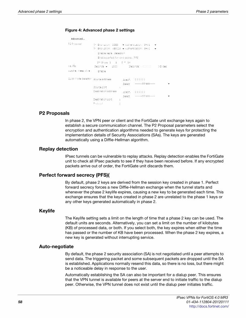
Advanced phase 2 settings Phase 2 parameters
Figure 4: Advanced phase 2 settings
P2 Proposals
In phase 2, the VPN peer or client and the FortiGate unit exchange keys again to
establish a secure communication channel. The P2 Proposal parameters select the
encryption and authentication algorithms needed to generate keys for protecting the
implementation details of Security Associations (SAs). The keys are generated
automatically using a Diffie-Hellman algorithm.
Replay detection
IPsec tunnels can be vulnerable to replay attacks. Replay detection enables the FortiGate
unit to check all IPsec packets to see if they have been received before. If any encrypted
packets arrive out of order, the FortiGate unit discards them.
Perfect forward secrecy (PFS)(
By default, phase 2 keys are derived from the session key created in phase 1. Perfect
forward secrecy forces a new Diffie-Hellman exchange when the tunnel starts and
whenever the phase 2 keylife expires, causing a new key to be generated each time. This
exchange ensures that the keys created in phase 2 are unrelated to the phase 1 keys or
any other keys generated automatically in phase 2.
Keylife
The Keylife setting sets a limit on the length of time that a phase 2 key can be used. The
default units are seconds. Alternatively, you can set a limit on the number of kilobytes
(KB) of processed data, or both. If you select both, the key expires when either the time
has passed or the number of KB have been processed. When the phase 2 key expires, a
new key is generated without interrupting service.
Auto-negotiate
By default, the phase 2 security association (SA) is not negotiated until a peer attempts to
send data. The triggering packet and some subsequent packets are dropped until the SA
is established. Applications normally resend this data, so there is no loss, but there might
be a noticeable delay in response to the user.
Automatically establishing the SA can also be important for a dialup peer. This ensures
that the VPN tunnel is available for peers at the server end to initiate traffic to the dialup
peer. Otherwise, the VPN tunnel does not exist until the dialup peer initiates traffic.
IPsec VPNs for FortiOS 4.0 MR3
58 01-434-112804-20120111
http://docs.fortinet.com/

Phase 2 parameters Advanced phase 2 settings
F
0
h
When enabled, auto-negotiate initiates the phase 2 SA negotiation automatically,
repeating every five seconds until the SA is established.
The auto-negotiate feature is available only through the Command Line Interface (CLI).
Use the following commands to enable it.
config vpn ipsec phase2edit <phase2_name>set auto-negotiate enable
end
If the tunnel goes down, the auto-negotiate feature will attempt to re-establish it.
However, the Autokey Keep Alive feature is a better method to ensure your VPN remains
up.
Autokey Keep Alive
The phase 2 SA has a fixed duration. If there is traffic on the VPN as the SA nears expiry,
a new SA is negotiated and the VPN switches to the new SA without interruption. If there
is no traffic, the SA expires and the VPN tunnel goes down. A new SA will not be
generated until there is traffic.
The Autokey Keep Alive option ensures that a new SA is negotiated even if there is no
traffic so that the VPN tunnel stays up.
DHCP-IPsec
Select this option if the FortiGate unit assigns VIP addresses to FortiClient dialup clients
through a DHCP server or relay. This option is available only if the Remote Gateway in the
phase 1 configuration is set to Dialup User and it works only on policy-based VPNs.
With the DHCP-IPsec option, the FortiGate dialup server acts as a proxy for FortiClient
dialup clients that have VIP addresses on the subnet of the private network behind the
FortiGate unit. In this case, the FortiGate dialup server acts as a proxy on the local private
network for the FortiClient dialup client. When a host on the network behind the dialup
server issues an ARP request that corresponds to the device MAC address of the
FortiClient host (when a remote server sends an ARP to the local FortiClient dialup client),
the FortiGate unit answers the ARP request on behalf of the FortiClient host and forwards
the associated traffic to the FortiClient host through the tunnel.
This feature prevents the VIP address assigned to the FortiClient dialup client from
causing possible arp broadcast problems—the normal and VIP addresses can confuse
some network switches by two addresses having the same MAC address.
Quick mode selectors
Quick Mode selectors determine which IP addresses can perform IKE negotiations to
establish a tunnel. By only allowing authorized IP addresses access to the VPN tunnel,
the network is more secure.
The default settings are as broad as possible: any IP address or configured address
group, using any protocol, on any port. This enables configurations in which multiple
subnets at each end of the tunnel can communicate, limited only by the security policies
at each end.
When configuring Quick Mode selector Source Address and Destination address, valid
options include IPv4 and IPv6 single addresses, IPv4 firewall address or group name,
IPv4 range, IPv6 range, IPv4 subnet, or IPv6 subnet. For more information on IPv6 IPsec
VPN, see “Overview of IPv6 IPsec support” on page 187.
ortiOS™ Handbook v3: IPsec VPNs
1-434-112804-20120111 59ttp://docs.fortinet.com/

Configure the phase 2 parameters Phase 2 parameters
There are some configurations that require specific selectors:
• the VPN peer is a third-party device that uses specific phase2 selectors
• the FortiGate unit connects as a dialup client to another FortiGate unit, in which case
you must specify a source IP address, IP address range or subnet
With FortiOS VPNs, your network has multiple layers of security, with quick mode
selectors being an important line of defence.
• Routes guide traffic from one IP address to another.
• Phase 1 and phase 2 connection settings ensure there is a valid remote end point for
the VPN tunnel that agrees on the encryption and parameters.
• Quick mode selectors allow IKE negotiations only for allowed peers.
• Security policies control which IP addresses can connect to the VPN.
• Security policies also control what protocols are allowed over the VPN along with any
bandwidth limiting.
Configure the phase 2 parameters
Follow this procedure to create an IPsec phase 2 definition.
Specifying the phase 2 parameters
1 Go to VPN > IPsec > Auto Key (IKE).
2 Select Create Phase 2.
3 Include appropriate entries as follows:
4 Select Advanced.
5 Include appropriate entries as follows:
If you are creating a hub-and-spoke configuration or an Internet-browsing configuration,
you may have already started defining some of the required phase 2 parameters. If so,
edit the existing definition to complete the configuration.
Name Enter a name to identify the phase 2 configuration.
Phase 1
Select the phase 1 configuration that describes how remote peers or
dialup clients will be authenticated on this tunnel, and how the
connection to the remote peer or dialup client will be secured.
P2 Proposal
Select the encryption and authentication algorithms that will be
used to change data into encrypted code.
Add or delete encryption and authentication algorithms as required.
Select a minimum of one and a maximum of three combinations.
The remote peer must be configured to use at least one of the
proposals that you define.
It is invalid to set both Encryption and Authentication to null.
IPsec VPNs for FortiOS 4.0 MR3
60 01-434-112804-20120111
http://docs.fortinet.com/
Phase 2 parameters Configure the phase 2 parameters
F
0
h
Encryption
You can select any of the following symmetric-key algorithms:
NULL — Do not use an encryption algorithm.
DES — Digital Encryption Standard, a 64-bit block algorithm that
uses a 56-bit key.
3DES — Triple-DES, in which plain text is encrypted three times by
three keys.
AES128 — A 128-bit block algorithm that uses a 128-bit key.
AES192 — A 128-bit block algorithm that uses a 192-bit key.
AES256 — A 128-bit block algorithm that uses a 256-bit key.
Authentication
You can select either of the following message digests to check the
authenticity of messages during an encrypted session:
• NULL — Do not use a message digest.
• MD5 — Message Digest 5, the hash algorithm developed by RSA
Data Security.
• SHA1 — Secure Hash Algorithm 1, which produces a 160-bit
message digest.
To specify one combination only, set the Encryption and
Authentication options of the second combination to NULL. To
specify a third combination, use the Add button beside the fields for
the second combination.
Enable replay
detection
Optionally enable or disable replay detection. Replay attacks occur
when an unauthorized party intercepts a series of IPsec packets
and replays them back into the tunnel.
Enable perfect
forward
secrecy (PFS)
Enable or disable PFS. Perfect forward secrecy (PFS) improves
security by forcing a new Diffie-Hellman exchange whenever keylife
expires.
DH GroupSelect one Diffie-Hellman group (1, 2, 5, or 14). The remote peer or
dialup client must be configured to use the same group.
Keylife
Select the method for determining when the phase 2 key expires:
Seconds, KBytes, or Both. If you select Both, the key expires when
either the time has passed or the number of KB have been
processed. The range is from 120 to 172800 seconds, or from 5120
to 2147483648 KB.
Autokey Keep
Alive
Enable the option if you want the tunnel to remain active when no
data is being processed.
DHCP-IPsec
Select Enable if the FortiGate unit acts as a dialup server and
FortiGate DHCP server or relay will be used to assign VIP addresses
to FortiClient dialup clients. The DHCP server or relay parameters
must be configured separately.
If the FortiGate unit acts as a dialup server and the FortiClient dialup
client VIP addresses match the network behind the dialup server,
select Enable to cause the FortiGate unit to act as a proxy for the
dialup clients.
This is available only for phase 2 configurations associated with a
dialup phase 1 configuration. It works only on policy-based VPNs.
ortiOS™ Handbook v3: IPsec VPNs
1-434-112804-20120111 61ttp://docs.fortinet.com/
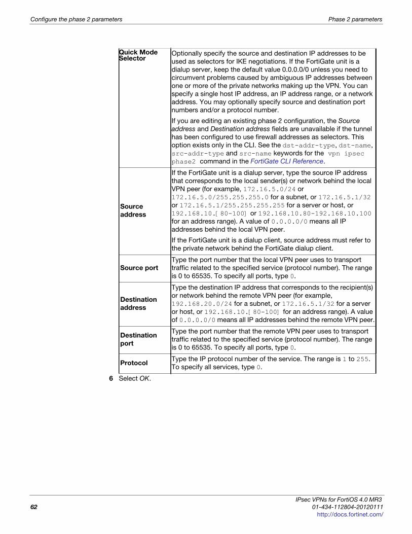
Configure the phase 2 parameters Phase 2 parameters
6 Select OK.
Quick Mode Selector
Optionally specify the source and destination IP addresses to be
used as selectors for IKE negotiations. If the FortiGate unit is a
dialup server, keep the default value 0.0.0.0/0 unless you need to
circumvent problems caused by ambiguous IP addresses between
one or more of the private networks making up the VPN. You can
specify a single host IP address, an IP address range, or a network
address. You may optionally specify source and destination port
numbers and/or a protocol number.
If you are editing an existing phase 2 configuration, the Source
address and Destination address fields are unavailable if the tunnel
has been configured to use firewall addresses as selectors. This
option exists only in the CLI. See the dst-addr-type, dst-name,
src-addr-type and src-name keywords for the vpn ipsec phase2 command in the FortiGate CLI Reference.
Source
address
If the FortiGate unit is a dialup server, type the source IP address
that corresponds to the local sender(s) or network behind the local
VPN peer (for example, 172.16.5.0/24 or
172.16.5.0/255.255.255.0 for a subnet, or 172.16.5.1/32
or 172.16.5.1/255.255.255.255 for a server or host, or
192.168.10.[80-100] or 192.168.10.80-192.168.10.100
for an address range). A value of 0.0.0.0/0 means all IP
addresses behind the local VPN peer.
If the FortiGate unit is a dialup client, source address must refer to
the private network behind the FortiGate dialup client.
Source port
Type the port number that the local VPN peer uses to transport
traffic related to the specified service (protocol number). The range
is 0 to 65535. To specify all ports, type 0.
Destination
address
Type the destination IP address that corresponds to the recipient(s)
or network behind the remote VPN peer (for example,
192.168.20.0/24 for a subnet, or 172.16.5.1/32 for a server
or host, or 192.168.10.[80-100] for an address range). A value
of 0.0.0.0/0 means all IP addresses behind the remote VPN peer.
Destination
port
Type the port number that the remote VPN peer uses to transport
traffic related to the specified service (protocol number). The range
is 0 to 65535. To specify all ports, type 0.
ProtocolType the IP protocol number of the service. The range is 1 to 255.
To specify all services, type 0.
IPsec VPNs for FortiOS 4.0 MR3
62 01-434-112804-20120111
http://docs.fortinet.com/

F o r t i O S H a n d b o o k
F
0
h
Defining VPN security policiesThis section explains how to specify the source and destination IP addresses of traffic
transmitted through an IPsec VPN, and how to define appropriate security policies.
The following topics are included in this section:
• Defining policy addresses
• Defining VPN security policies
Defining policy addresses
A VPN tunnel has two end points. These end points may be VPN peers such as two
FortiGate gateways. Encrypted packets are transmitted between the end points. At each
end of the VPN tunnel, a VPN peer intercepts encrypted packets, decrypts the packets,
and forwards the decrypted IP packets to the intended destination.
You need to define firewall addresses for the private networks behind each peer. You will
use these addresses as the source or destination address depending on the security
policy.
Figure 5: Example topology for the following policies
In general:
• In a gateway-to-gateway, hub-and-spoke, dynamic DNS, redundant-tunnel, or
transparent configuration, you need to define a policy address for the private IP
address of the network behind the remote VPN peer (for example,
192.168.10.0/255.255.255.0 or 192.168.10.0/24).
• In a peer-to-peer configuration, you need to define a policy address for the private IP
address of a server or host behind the remote VPN peer (for example,
172.16.5.1/255.255.255.255 or 172.16.5.1/32 or 172.16.5.1).
FortiGate B(remote)FortiG
ate A
(local)
192.168.2.0/24
192.168.10.0/24
Port 3FoFoFoFoFoForttrtrtrtrt GiGiGGiGiGiGatatatatatateeee e AA
cal)
FooForttrtiGiGiGatatee BB(rem
PPPPPoPort
Server (local)
Server (remote)
172.16.5.1/32
Port 2
Port 3
Port 2 Port 4
(dmz)Port 4 (dmz)
Private network
(local)
Private network(remote)
VPN connection
ortiOS™ Handbook v3: IPsec VPNs
1-434-112804-20120111 63ttp://docs.fortinet.com/

Defining VPN security policies Defining VPN security policies
For a FortiGate dialup server in a dialup-client or Internet-browsing configuration:
• If you are not using VIP addresses, or if the FortiGate dialup server assigns VIP
addresses to FortiClient dialup clients through FortiGate DHCP relay, select the
predefined destination address “all” in the security policy to refer to the dialup clients.
• If you assign VIP addresses to FortiClient dialup clients manually, you need to define a
policy address for the VIP address assigned to the dialup client (for example,
10.254.254.1/32), or a subnet address from which the VIP addresses are assigned
(for example, 10.254.254.0/24 or 10.254.254.0/255.255.255.0).
• For a FortiGate dialup client in a dialup-client or Internet-browsing configuration, you
need to define a policy address for the private IP address of a host, server, or network
behind the FortiGate dialup server.
To define a security IP address
1 Go to Firewall Objects> Address > Address and select Create New.
2 In the Address Name field, type a descriptive name that represents the network,
server(s), or host(s).
3 In Type, select Subnet / IP Range.
4 In the Subnet/IP Range field, type the corresponding IP address and subnet mask.
For a subnet you could use the format 172.16.5.0/24 or its equivalent
172.16.5.0/255.255.255.0. For a server or host it would likely be
172.16.5.1/32. Alternately you can use an IP address range such as
192.168.10.[80-100] or 192.168.10.80-192.168.10.100.
5 Select OK.
Defining VPN security policies
Security policies allow IP traffic to pass between interfaces on a FortiGate unit. You can
limit communication to particular traffic by specifying source address and destination
addresses. Then only traffic from those addresses will be allowed.
Policy-based and route-based VPNs require different security policies.
• A policy-based VPN requires an IPsec security policy. You specify the interface to the
private network, the interface to the remote peer and the VPN tunnel. A single policy
can enable traffic inbound, outbound, or in both directions.
• A route-based VPN requires an Accept security policy for each direction. As source
and destination interfaces, you specify the interface to the private network and the
virtual IPsec interface (phase 1 configuration) of the VPN. The IPsec interface is the
destination interface for the outbound policy and the source interface for the inbound
policy. One security policy must be configured for each direction of each VPN
interface.
There are examples of security policies for both policy-based and route-based VPNs
throughout this guide. See “Route-based or policy-based VPN” on page 103.
If the security policy, which grants the VPN Connection is limited to certain services,
DHCP must be included, otherwise the client won’t be able to retrieve a lease from the
FortiGate’s (IPSec) DHCP server, because the DHCP Request (coming out of the tunnel)
will be blocked.
IPsec VPNs for FortiOS 4.0 MR3
64 01-434-112804-20120111
http://docs.fortinet.com/

Defining VPN security policies Defining VPN security policies
F
0
h
Defining an IPsec security policy for a policy-based VPN
An IPsec security policy enables the transmission and reception of encrypted packets,
specifies the permitted direction of VPN traffic, and selects the VPN tunnel. In most
cases, a single policy is needed to control both inbound and outbound IP traffic through a
VPN tunnel.
Allow outbound and allow inboundIn addition to these operations, security policies specify which IP addresses can initiate a
tunnel. When the Allow outbound option is selected, traffic from the local private network
initiates the tunnel. When the Allow inbound option is selected, traffic from a dialup client
or computers on the remote network initiates the tunnel. Both can be enabled at the
same time for bi-directional initiation of the tunnel.
Outbound and inbound NATWhen a FortiGate unit operates in NAT mode, you can also enable inbound or outbound
NAT. Outbound NAT may be performed on outbound encrypted packets, or on IP packets
before they are sent through the tunnel. Inbound NAT is performed on IP packets
emerging from the tunnel. By default, these options are not selected in security policies.
• When used in conjunction with the natip CLI attribute (see the “config firewall”
chapter of the FortiGate CLI Reference), outbound NAT enables you to change the
source addresses of IP packets before they go into the tunnel. This feature is often
used to resolve ambiguous routing when two or more of the private networks making
up a VPN have the same or overlapping IP addresses. .
When inbound NAT is enabled, inbound encrypted packets are intercepted and
decrypted, and the source IP addresses of the decrypted packets are translated into the
IP address of the FortiGate interface to the local private network before they are routed to
the private network. If the computers on the local private network can communicate only
with devices on the local private network (that is, the FortiGate interface to the private
network is not the default gateway) and the remote client (or remote private network)
does not have an IP address in the same network address space as the local private
network, enable inbound NAT.
Source and destination addressesMost security policies control outbound IP traffic. A VPN outbound policy usually has a
source address originating on the private network behind the local FortiGate unit, and a
destination address belonging to a dialup VPN client or a network behind the remote VPN
peer. The source address that you choose for the security policy identifies from where
outbound cleartext IP packets may originate, and also defines the local IP address or
addresses that a remote server or client will be allowed to access through the VPN
tunnel. The destination address that you choose identifies where IP packets must be
forwarded after they are decrypted at the far end of the tunnel, and determines the IP
address or addresses that the local network will be able to access at the far end of the
tunnel.
Enabling other policy featuresYou can fine-tune a policy for services such as HTTP, FTP, and POP3; enable logging,
traffic shaping, antivirus protection, web filtering, email filtering, file transfer, and email
services throughout the VPN; and optionally allow connections according to a predefined
schedule.
ortiOS™ Handbook v3: IPsec VPNs
1-434-112804-20120111 65ttp://docs.fortinet.com/

Defining VPN security policies Defining VPN security policies
When a remote server or client attempts to connect to the private network behind a
FortiGate gateway, the security policy intercepts the connection attempt and starts the
VPN tunnel. The FortiGate unit uses the remote gateway specified in its phase 1 tunnel
configuration to reply to the remote peer. When the remote peer receives a reply, it
checks its own security policy, including the tunnel configuration, to determine which
communications are permitted. As long as one or more services are allowed through the
VPN tunnel, the two peers begin to negotiate the tunnel. To follow this negotiation in the
web-based manager, go to VPN > Monitor > IPsec Monitor. There you will find a list of the
VPN tunnels, their status, and the data flow both incoming and outgoing.
Before you beginBefore you define the IPsec policy, you must:
• Define the IP source and destination addresses. See “Defining policy addresses” on
page 63.
• Specify the phase 1 authentication parameters. See “Auto Key phase 1 parameters”
on page 39.
• Specify the phase 2 parameters. See “Phase 2 parameters” on page 57.
To define an IPsec security policy
1 Go to Policy > Policy > Policy and select Create New.
2 Include the settings as follows:
As an option, differentiated services (diffserv or DSCP) can be enabled in the security
policy through CLI commands. For more information on this feature, see FortiOS
Handbook Traffic Shaping guide or the “firewall” chapter of the FortiGate CLI Reference.
Source Interface/ZoneSelect the local interface to the internal (private)
network.
Source Address Name
Select the name that corresponds to the local network,
server(s), or host(s) from which IP packets may
originate.
Destination
Interface/Zone
Select the local interface to the external (public)
network.
Destination Address
Name
Select the name that corresponds to the remote
network, server(s), or host(s) to which IP packets may
be delivered.
ScheduleKeep the default setting (always) unless changes are
needed to meet specific requirements.
ServiceKeep the default setting (ANY) unless changes are
needed to meet your specific requirements.
Action Select IPSEC.
VPN TunnelSelect the name of the phase 1 tunnel configuration to
which this policy will apply.
Allow InboundSelect if traffic from the remote network will be allowed
to initiate the tunnel.
Allow OutboundSelect if traffic from the local network will be allowed to
initiate the tunnel.
IPsec VPNs for FortiOS 4.0 MR3
66 01-434-112804-20120111
http://docs.fortinet.com/
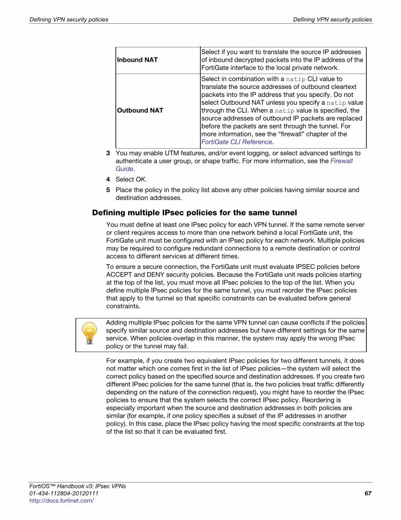
Defining VPN security policies Defining VPN security policies
F
0
h
3 You may enable UTM features, and/or event logging, or select advanced settings to
authenticate a user group, or shape traffic. For more information, see the Firewall
Guide.
4 Select OK.
5 Place the policy in the policy list above any other policies having similar source and
destination addresses.
Defining multiple IPsec policies for the same tunnel You must define at least one IPsec policy for each VPN tunnel. If the same remote server
or client requires access to more than one network behind a local FortiGate unit, the
FortiGate unit must be configured with an IPsec policy for each network. Multiple policies
may be required to configure redundant connections to a remote destination or control
access to different services at different times.
To ensure a secure connection, the FortiGate unit must evaluate IPSEC policies before
ACCEPT and DENY security policies. Because the FortiGate unit reads policies starting
at the top of the list, you must move all IPsec policies to the top of the list. When you
define multiple IPsec policies for the same tunnel, you must reorder the IPsec policies
that apply to the tunnel so that specific constraints can be evaluated before general
constraints.
For example, if you create two equivalent IPsec policies for two different tunnels, it does
not matter which one comes first in the list of IPsec policies—the system will select the
correct policy based on the specified source and destination addresses. If you create two
different IPsec policies for the same tunnel (that is, the two policies treat traffic differently
depending on the nature of the connection request), you might have to reorder the IPsec
policies to ensure that the system selects the correct IPsec policy. Reordering is
especially important when the source and destination addresses in both policies are
similar (for example, if one policy specifies a subset of the IP addresses in another
policy). In this case, place the IPsec policy having the most specific constraints at the top
of the list so that it can be evaluated first.
Inbound NAT
Select if you want to translate the source IP addresses
of inbound decrypted packets into the IP address of the
FortiGate interface to the local private network.
Outbound NAT
Select in combination with a natip CLI value to
translate the source addresses of outbound cleartext
packets into the IP address that you specify. Do not
select Outbound NAT unless you specify a natip value
through the CLI. When a natip value is specified, the
source addresses of outbound IP packets are replaced
before the packets are sent through the tunnel. For
more information, see the “firewall” chapter of the
FortiGate CLI Reference.
Adding multiple IPsec policies for the same VPN tunnel can cause conflicts if the policies
specify similar source and destination addresses but have different settings for the same
service. When policies overlap in this manner, the system may apply the wrong IPsec
policy or the tunnel may fail.
ortiOS™ Handbook v3: IPsec VPNs
1-434-112804-20120111 67ttp://docs.fortinet.com/

Defining VPN security policies Defining VPN security policies
Defining security policies for a route-based VPN
When you define a route-based VPN, you create a virtual IPsec interface on the physical
interface that connects to the remote peer. You create ordinary Accept security policies to
enable traffic between the IPsec interface and the interface that connects to the private
network. This makes configuration simpler than for policy-based VPNs, which require
IPsec security policies.
To define security policies for a route-based VPN
1 Define an ACCEPT security policy to permit communications between the local
private network and the private network behind the remote peer. Enter these settings
in particular:
2 To permit the remote client to initiate communication, you need to define a security
policy for communication in that direction. Enter these settings in particular:
Source Interface/ZoneSelect the interface that connects to the private
network behind this FortiGate unit.
Source Address NameSelect the address name that you defined for the
private network behind this FortiGate unit.
Destination Interface/Zone Select the IPsec Interface you configured.
Destination Address NameSelect the address name that you defined for the
private network behind the remote peer.
Action Select ACCEPT.
NAT Disable.
Source Interface/Zone Select the IPsec Interface you configured.
Source Address NameSelect the address name that you defined for the
private network behind the remote peer.
Destination Interface/ZoneSelect the interface that connects to the private
network behind this FortiGate unit.
Destination Address NameSelect the address name that you defined for the
private network behind this FortiGate unit.
Action Select ACCEPT.
NAT Disable.
IPsec VPNs for FortiOS 4.0 MR3
68 01-434-112804-20120111
http://docs.fortinet.com/

F o r t i O S H a n d b o o k
F
0
h
Gateway-to-gateway configurations This section explains how to set up a basic gateway-to-gateway (site-to-site) IPsec VPN.
The following topics are included in this section:
• Configuration overview
• General configuration steps
• Configuring the two VPN peers
• How to work with overlapping subnets
• Testing
Configuration overview
In a gateway-to-gateway configuration, two FortiGate units create a VPN tunnel between
two separate private networks. All traffic between the two networks is encrypted and
protected by FortiGate security policies.
Figure 6: Example gateway-to-gateway configuration
In some cases, computers on the private network behind one VPN peer may (by co-
incidence) have IP addresses that are already used by computers on the network behind
the other VPN peer. In this type of situation (ambiguous routing), conflicts may occur in
one or both of the FortiGate routing tables and traffic destined for the remote network
through the tunnel may not be sent. To resolve issues related to ambiguous routing, see
“How to work with overlapping subnets” on page 76.
In other cases, computers on the private network behind one VPN peer may obtain IP
addresses from a local DHCP server. However, unless the local and remote networks use
different private network address spaces, unintended ambiguous routing and/or IP-
address overlap issues may arise. For a discussion of the related issues, see “FortiGate
dialup-client configurations” on page 133.
You can set up a fully meshed or partially meshed configuration (see Figure 7 and
Figure 8).
FortiGate_2FortiGate_1
FortiGate_ rtiGate_2
10.21.101.0/24
wan1172.18.0.2
10.31.101.0/24
w
an1
172.20.0.2
Finance departmentHR department
ortiOS™ Handbook v3: IPsec VPNs
1-434-112804-20120111 69ttp://docs.fortinet.com/

Configuration overview Gateway-to-gateway configurations
Figure 7: Fully meshed configuration
In a fully meshed network, all VPN peers are connected to each other, with one hop
between peers. This topology is the most fault-tolerant: if one peer goes down, the rest of
the network is not affected. This topology is difficult to scale because it requires
connections between all peers. In addition, unnecessary communication can occur
between peers. Best practices dictates a hub-and-spoke configuration instead (see
“Hub-and-spoke configurations” on page 85).
Figure 8: Partially meshed configuration
A partially meshed network is similar to a fully meshed network, but instead of having
tunnels between all peers, tunnels are only configured between peers that communicate
with each other regularly.
FortiGate_3FortiGate_2
FortiGate_
FortiGate_5
FoFoFoFoFoFoFo trtrtrtrtrtrt GiGiGiGiGiGGiGaattatatatatee_e_555
FortiGate_1
FortiGate_
rtiGate_3
FortiGate_4
rtiGate_4
FortiGate_3FortiGate_2
FortiGate_
FortiGate_5
FoFoFoFoFoFoFo trtrtrtrtrtrt GiGiGiGiGiGGiGaattatatatatee_e_555
FortiGate_1
FortiGate_
rtiGate_3
FortiGate_4
rtiGate_4
IPsec VPNs for FortiOS 4.0 MR3
70 01-434-112804-20120111
http://docs.fortinet.com/

Gateway-to-gateway configurations General configuration steps
F
0
h
General configuration steps
The FortiGate units at both ends of the tunnel must be operating in NAT mode and have
static public IP addresses.
When a FortiGate unit receives a connection request from a remote VPN peer, it uses
IPsec phase 1 parameters to establish a secure connection and authenticate that VPN
peer. Then, if the security policy permits the connection, the FortiGate unit establishes
the tunnel using IPsec phase 2 parameters and applies the IPsec security policy. Key
management, authentication, and security services are negotiated dynamically through
the IKE protocol.
To support these functions, the following general configuration steps must be performed
by both FortiGate units:
• Define the phase 1 parameters that the FortiGate unit needs to authenticate the
remote peer and establish a secure connection.
• Define the phase 2 parameters that the FortiGate unit needs to create a VPN tunnel
with the remote peer.
• Create security policies to control the permitted services and permitted direction of
traffic between the IP source and destination addresses.
Configuring the two VPN peers
Configure the VPN peers as follows. Each step is required, but these are general steps.
For more detailed information on each step follow the cross references. See “Auto Key
phase 1 parameters” on page 39.
Configuring Phase 1 and Phase 2 for both peers
This procedure applies to both peers. Repeat the procedure on each FortiGate unit, using
the correct IP address for each. You may wish to vary the Phase 1 names but this is
optional. Otherwise all steps are the same for each peer.
The phase 1 configuration defines the parameters that FortiGate_1 will use to
authenticate FortiGate_2 and establish a secure connection. For the purposes of this
example, a preshared key will be used to authenticate FortiGate_2. The same preshared
key must be specified at both FortiGate units.
Before you define the phase 1 parameters, you need to:
• Reserve a name for the remote gateway.
• Obtain the IP address of the public interface to the remote peer.
• Reserve a unique value for the preshared key.
The key must contain at least 6 printable characters and best practices dictate that it only
be known by network administrators. For optimum protection against currently known
attacks, the key must have a minimum of 16 randomly chosen alphanumeric characters.
At the local FortiGate unit, define the phase 1 configuration needed to establish a secure
connection with the remote peer. See “Phase 1 configuration” on page 26.
All steps are required. Cross references point to required information that is repeated. No
steps are optional.
ortiOS™ Handbook v3: IPsec VPNs
1-434-112804-20120111 71ttp://docs.fortinet.com/

Configuring the two VPN peers Gateway-to-gateway configurations
To create phase 1 to establish a secure connection with the remote peer
1 Go to VPN > IPsec > Auto Key (IKE).
2 Select Create Phase 1.
3 Enter the following information, and select OK.
The basic phase 2 settings associate IPsec phase 2 parameters with the phase 1
configuration and specify the remote end point of the VPN tunnel. Before you define the
phase 2 parameters, you need to reserve a name for the tunnel. See “Phase 2
configuration” on page 31.
To configure phase 2 settings
1 Go to VPN > IPsec > Auto Key (IKE).
2 Select Create Phase 2.
3 Enter the following information, and select OK.
Creating security policies
Security policies control all IP traffic passing between a source address and a destination
address.
Name
Enter peer_1.
A name to identify the VPN tunnel. This name appears in
phase 2 configurations, security policies and the VPN monitor.
Remote Gateway Select Static IP Address.
IP Address
Enter 172.20.0.2 when configuring FortiGate_1.
Enter 172.18.0.2 when configuring FortiGate_2.
The IP address of the remote peer public interface.
Local Interface
Select wan1.
The FortiGate unit’s public interface.
This interface cannot be a loopback interface.
Enable IPsec
Interface Mode
Select Advanced to see this setting.
Enable IPsec Interface Mode to have the FortiGate unit create a
virtual IPsec interface for a route-based VPN.
Disable this option to create a policy-based VPN. For more
information, see “Comparing policy-based or route-based
VPNs” on page 22.
After you select OK to create the phase 1 configuration, you
cannot change this setting.
NameEnter peer_1_p2.
A name to identify this phase 2 configuration.
Phase 1Select peer_1.
The name of the phase 1 configuration.
IPsec VPNs for FortiOS 4.0 MR3
72 01-434-112804-20120111
http://docs.fortinet.com/
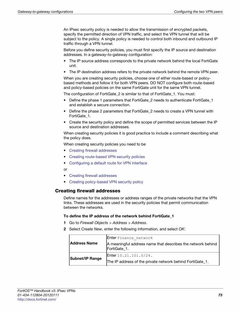
Gateway-to-gateway configurations Configuring the two VPN peers
F
0
h
An IPsec security policy is needed to allow the transmission of encrypted packets,
specify the permitted direction of VPN traffic, and select the VPN tunnel that will be
subject to the policy. A single policy is needed to control both inbound and outbound IP
traffic through a VPN tunnel.
Before you define security policies, you must first specify the IP source and destination
addresses. In a gateway-to-gateway configuration:
• The IP source address corresponds to the private network behind the local FortiGate
unit.
• The IP destination address refers to the private network behind the remote VPN peer.
When you are creating security policies, choose one of either route-based or policy-
based methods and follow it for both VPN peers. DO NOT configure both route-based
and policy-based policies on the same FortiGate unit for the same VPN tunnel.
The configuration of FortiGate_2 is similar to that of FortiGate_1. You must:
• Define the phase 1 parameters that FortiGate_2 needs to authenticate FortiGate_1
and establish a secure connection.
• Define the phase 2 parameters that FortiGate_2 needs to create a VPN tunnel with
FortiGate_1.
• Create the security policy and define the scope of permitted services between the IP
source and destination addresses.
When creating security policies it is good practice to include a comment describing what
the policy does.
When creating security policies you need to be
• Creating firewall addresses
• Creating route-based VPN security policies
• Configuring a default route for VPN interface
or
• Creating firewall addresses
• Creating policy-based VPN security policy
Creating firewall addressesDefine names for the addresses or address ranges of the private networks that the VPN
links. These addresses are used in the security policies that permit communication
between the networks.
To define the IP address of the network behind FortiGate_1
1 Go to Firewall Objects > Address > Address.
2 Select Create New, enter the following information, and select OK:
Address Name
Enter Finance_network
A meaningful address name that describes the network behind
FortiGate_1.
Subnet/IP RangeEnter 10.21.101.0/24.
The IP address of the private network behind FortiGate_1.
ortiOS™ Handbook v3: IPsec VPNs
1-434-112804-20120111 73ttp://docs.fortinet.com/
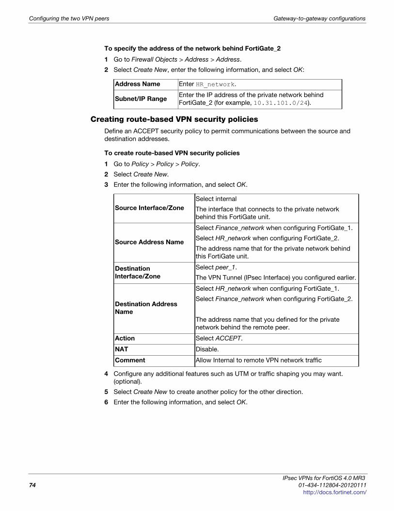
Configuring the two VPN peers Gateway-to-gateway configurations
To specify the address of the network behind FortiGate_2
1 Go to Firewall Objects > Address > Address.
2 Select Create New, enter the following information, and select OK:
Creating route-based VPN security policiesDefine an ACCEPT security policy to permit communications between the source and
destination addresses.
To create route-based VPN security policies
1 Go to Policy > Policy > Policy.
2 Select Create New.
3 Enter the following information, and select OK.
4 Configure any additional features such as UTM or traffic shaping you may want.
(optional).
5 Select Create New to create another policy for the other direction.
6 Enter the following information, and select OK.
Address Name Enter HR_network.
Subnet/IP RangeEnter the IP address of the private network behind
FortiGate_2 (for example, 10.31.101.0/24).
Source Interface/Zone
Select internal
The interface that connects to the private network
behind this FortiGate unit.
Source Address Name
Select Finance_network when configuring FortiGate_1.
Select HR_network when configuring FortiGate_2.
The address name that for the private network behind
this FortiGate unit.
Destination
Interface/Zone
Select peer_1.
The VPN Tunnel (IPsec Interface) you configured earlier.
Destination Address
Name
Select HR_network when configuring FortiGate_1.
Select Finance_network when configuring FortiGate_2.
The address name that you defined for the private
network behind the remote peer.
Action Select ACCEPT.
NAT Disable.
Comment Allow Internal to remote VPN network traffic
IPsec VPNs for FortiOS 4.0 MR3
74 01-434-112804-20120111
http://docs.fortinet.com/

Gateway-to-gateway configurations Configuring the two VPN peers
F
0
h
7 Configure any additional features such as UTM or traffic shaping you may want.
(optional).
Configuring a default route for VPN interfaceAll network traffic must have a static route to direct its traffic to the proper destination.
Without a route, traffic will not flow even if the security policies are configured properly.
You may need to create a static route entry for both directions of VPN traffic if your
security policies allow bi-directional tunnel initiation.
To configure the route for a route-based VPN
1 On FortiGate_2, go to Router > Static > Static Route.
2 Select Create New, enter the following information, and then select OK:
Source Interface/ZoneSelect peer_1.
The VPN Tunnel (IPsec Interface) you configured.
Source Address Name
Select HR_network when configuring FortiGate_1.
Select Finance_Network when configuring FortiGate_2.
The address name defined for the private network
behind the remote peer.
Destination
Interface/Zone
Select internal
The interface that connects to the private network
behind this FortiGate unit.
Destination Address
Name
Select Finance_Network when configuring FortiGate_1.
Select HR_network when configuring FortiGate_2.
The address name defined for the private network
behind this FortiGate unit.
Action Select ACCEPT.
NAT Disable.
Comment Allow remote VPN network traffic to Internal.
Destination IP /
Mask
10.21.101.0/24
Device FGT2_to_FGT1_Tunnel
Gateway Leave as default: 0.0.0.0.
Distance
Leave this at its default.
If there are other routes on this FortiGate unit, you may need
to set the distance on this route so the VPN traffic will use it
as the default route. However, this normally happens by
default because this route is typically a better match than the
generic default route.
ortiOS™ Handbook v3: IPsec VPNs
1-434-112804-20120111 75ttp://docs.fortinet.com/

How to work with overlapping subnets Gateway-to-gateway configurations
Creating policy-based VPN security policyDefine an IPsec security policy to permit communications between the source and
destination addresses.
How to work with overlapping subnets
A site-to-site VPN configuration sometimes has the problem that the private subnet
addresses at each end are the same. You can resolve this problem by remapping the
private addresses using virtual IP addresses (VIP).
VIPs allow computers on those overlapping private subnets to each have another set of
IP addresses that can be used without confusion. The FortiGate unit maps the VIP
addresses to the original addresses. This means if PC1 starts a session with PC2 at
10.31.101.10, FortiGate_2 directs that session to 10.11.101.10 — the actual IP address
of PC2. Figure 9 shows this — Finance network VIP is 10.21.101.0/24 and the HR
network is 10.31.101.0/24.
Source Interface/Zone
Select internal.
The interface that connects to the private network
behind this FortiGate unit.
Source Address Name
Select Finance_network when configuring FortiGate_1.
Select HR_network when configuring FortiGate_2.
The address name defined for the private network
behind this FortiGate unit.
Destination
Interface/Zone
Select wan1.
The FortiGate unit’s public interface.
Destination Address
Name
Select HR_network when configuring FortiGate_1.
Select Finance_network when configuring FortiGate_2.
The address name that you defined in Step for the
private network behind the remote peer.
Action Select IPSEC.
VPN Tunnel
Select peer_1.
The name of the phase 1 configuration that you created
earlier.
Select Allow inbound to enable traffic from the remote
network to initiate the tunnel.
Select Allow outbound to enable traffic from the local
network to initiate the tunnel.
Comment Bidirectional policy-based VPN policy
Place VPN policies in the policy list above any other policies having similar source and
destination addresses.
IPsec VPNs for FortiOS 4.0 MR3
76 01-434-112804-20120111
http://docs.fortinet.com/
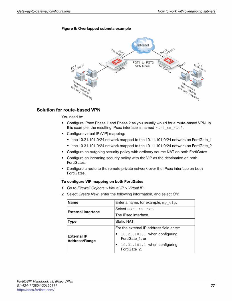
Gateway-to-gateway configurations How to work with overlapping subnets
F
0
h
Figure 9: Overlapped subnets example
Solution for route-based VPN
You need to:
• Configure IPsec Phase 1 and Phase 2 as you usually would for a route-based VPN. In
this example, the resulting IPsec interface is named FGT1_to_FGT2.
• Configure virtual IP (VIP) mapping:
• the 10.21.101.0/24 network mapped to the 10.11.101.0/24 network on FortiGate_1
• the 10.31.101.0/24 network mapped to the 10.11.101.0/24 network on FortiGate_2
• Configure an outgoing security policy with ordinary source NAT on both FortiGates.
• Configure an incoming security policy with the VIP as the destination on both
FortiGates.
• Configure a route to the remote private network over the IPsec interface on both
FortiGates.
To configure VIP mapping on both FortiGates
1 Go to Firewall Objects > Virtual IP > Virtual IP.
2 Select Create New, enter the following information, and select OK:
FortiGate_1
Finance network
10.11.101.0/24
(VIP 10.21.101.0/24)
Port 1
Port 2172.16.20.1
PC 1
10.11.101.10 FortiGate_2
HR network10.11.101.0/24
(VIP 10.31.101.0/24)
Port 2
172.16.30.1
Port 1 PC 210.11.101.10
FoFoFFoFoFortrtrtrtrtiGiGiGiGGiGatatatatateeeee
PPPo
FoFoFoFooFo trtrtrtrtiGiGiGiGiGiGattatatatateeeee_e_1t 111
FGT1_to_FGT2 VPN tunnel
Name Enter a name, for example, my_vip.
External InterfaceSelect FGT1_to_FGT2.
The IPsec interface.
Type Static NAT
External IP
Address/Range
For the external IP address field enter:
• 10.21.101.1 when configuring
FortiGate_1, or
• 10.31.101.1 when configuring
FortiGate_2.
ortiOS™ Handbook v3: IPsec VPNs
1-434-112804-20120111 77ttp://docs.fortinet.com/
How to work with overlapping subnets Gateway-to-gateway configurations
To configure the outbound security policy on both FortiGates
Repeat this procedure on both FortiGate_1 and FortiGate_2.
1 Go to Policy > Policy > Policy.
2 Select Create New.
3 Enter the following information, and select OK:
To configure the inbound security policy on both FortiGates
Repeat this procedure on both FortiGate_1 and FortiGate_2.
1 Go to Policy > Policy > Policy.
2 Select Create New, enter the following information, and then select OK:
Mapped IP
Address/Range
For the Mapped IP Address enter
10.11.101.1.
For the Range enter 10.11.101.254.
Port Forwarding Disable
Source Interface/Zone Select Port 1.
Source Address Name Select all.
Destination
Interface/Zone
Select FGT1_to_FGT2.
The IPsec interface.
Destination Address
Name
Select all.
Schedule As required.
Service As required.
Action ACCEPT
NAT Enable
Source Interface/Zone Select FGT1_to_FGT2.
Source Address Name Select all.
Destination
Interface/Zone
Select Port 1.
Destination Address
Name
Select my-vip.
Schedule As required.
Service As required.
Action ACCEPT
NAT Disable
IPsec VPNs for FortiOS 4.0 MR3
78 01-434-112804-20120111
http://docs.fortinet.com/
Gateway-to-gateway configurations How to work with overlapping subnets
F
0
h
To configure the static route for both FortiGates
Repeat this procedure on both FortiGate_1 and FortiGate_2.
1 Go to Router > Static > Static Route.
2 Select Create New, enter the following information, and then select OK:
Solution for policy-based VPN
As with the route-based solution, users contact hosts at the other end of the VPN using
an alternate subnet address. PC1 communicates with PC2 using IP address
10.31.101.10, and PC2 communicates with PC1 using IP address 10.21.101.10.
In this solution however, outbound NAT is used to translate the source address of
packets from the 10.11.101.0/24 network to the alternate subnet address that hosts at
the other end of the VPN use to reply. Inbound packets from the remote end have their
destination addresses translated back to the 10.11.101.0/24 network.
For example, PC1 uses the destination address 10.31.101.10 to contact PC2. Outbound
NAT on FortiGate_1 translates the PC1 source address to 10.21.101.10. At the
FortiGate_2 end of the tunnel, the outbound NAT configuration translates the destination
address to the actual PC2 address of 10.11.101.10. Similarly, PC2 replies to PC1 using
destination address 10.21.101.10, with the PC2 source address translated to
10.31.101.10. PC1 and PC2 can communicate over the VPN even though they both have
the same IP address.
You need to:
• Configure IPsec Phase 1 as you usually would for a policy-based VPN.
• Configure IPsec Phase 2 with the use-natip disable CLI option.
• Define a firewall address for the local private network, 10.11.101.0/24.
• Define a firewall address for the remote private network:
• define a firewall address for 10.31.101.0/24 on FortiGate_1
• define a firewall address for 10.21.101.0/24 on FortiGate_2
• Configure an outgoing IPsec security policy with outbound NAT to map
10.11.101.0/24 source addresses:
• to the 10.21.101.0/24 network on FortiGate_1
• to the 10.31.101.0/24 network on FortiGate_2
Destination IP /
Mask
Enter 10.31.101.0/24 when configuring FortiGate_1
Enter 10.21.101.0/24 when configuring FortiGate_2
Device Select FGT1_to_FGT2.
Gateway Leave as default: 0.0.0.0.
Distance
Leave at default.
If you have advanced routing on your network, you may have
to change this value.
If you do not add a static route for the VPN tunnel, no traffic will be sent or received.
ortiOS™ Handbook v3: IPsec VPNs
1-434-112804-20120111 79ttp://docs.fortinet.com/
How to work with overlapping subnets Gateway-to-gateway configurations
To configure IPsec Phase 2 - CLI
config vpn ipsec phase2edit "FGT1_FGT2_p2"set keepalive enableset pfs enableset phase1name FGT1_to_FGT2set proposal 3des-sha1 3des-md5set replay enableset use-natip disable
end
In this example, your phase 1 definition is named FGT1_to_FGT2. use-natip is set to
disable, so you can specify the source selector using the src-addr-type, src-start-ip / src-end-ip or src-subnet keywords. This example leaves these
keywords at their default values, which specify the subnet 0.0.0.0/0.
The pfs keyword ensures that perfect forward secrecy (PFS) is used. This ensures that
each Phase 2 key created is unrelated to any other keys in use.
To define the local private network firewall address
1 Go to Firewall Objects > Address > Address.
2 Select Create New and enter the following information:
To define the remote private network firewall address
1 Go to Firewall Objects > Address > Address.
2 Select Create New.
3 Enter the following information, and select OK:
Address NameEnter vpn-local.
A meaningful name for the local private network
Type Subnet / IP Range
Subnet / IP Range 10.11.101.0 255.255.255.0
Interface Any
Address NameEnter vpn-remote.
A meaningful name for the remote private network.
Type Subnet / IP Range
Subnet / IP Range10.31.101.0 255.255.255.0 on FortiGate_1
10.21.101.0 255.255.255.0 on FortiGate_2
Interface Any
IPsec VPNs for FortiOS 4.0 MR3
80 01-434-112804-20120111
http://docs.fortinet.com/

Gateway-to-gateway configurations Testing
F
0
h
To configure the IPsec security policy
In the CLI on FortiGate_1, enter the commands:
config firewall policyedit 1set srcintf "port1"set dstintf "port2"set srcaddr "vpn-local"set dstaddr "vpn-remote"set action ipsecset schedule "always"set service "ANY"set inbound enableset outbound enableset vpntunnel "FGT1_to_FGT2"set natoutbound enableset natip 10.31.101.0 255.255.255.0
end
Optionally, you can set everything except natip in the web-based manager and then
use the CLI to set natip.
Enter the same commands on FortiGate_2, but set natip be 10.21.101.0 255.255.255.0.
Testing
The best testing is to look at the packets both as the VPN tunnel is negotiated, and when
the tunnel is up.
To determine what the other end of the VPN tunnel is proposing
1 Start a terminal program such as puTTY and set it to log all output.
When necessary refer to the logs to locate information when output is verbose.
2 Logon to the FortiGate unit using a super_admin account.
3 Enter the following CLI commands.
4 Display all the possible IKE error types and the number of times they have occurred:
diag vpn ike errors
5 Check for existing debug sessions:
diag debug info
If a debug session is running, to halt it enter:
diag debug disable
6 Confirm your proposal settings:
diag vpn ike config list
7 If your proposal settings do not match what you expect, make a change to it and save
it to force an update in memory. If that fixes the problem, stop here.
8 List the current vpn filter:
diag vpn ike filter
ortiOS™ Handbook v3: IPsec VPNs
1-434-112804-20120111 81ttp://docs.fortinet.com/
Testing Gateway-to-gateway configurations
9 If all fields are set to any, there are no filters set and all VPN ike packets will be
displayed in the debug output. If your system has only a few VPNs, skip setting the
filter.
If your system has many VPN connections this will result in very verbose output and
make it very difficult to locate the correct connection attempt.
10 Set the VPN filter to display only information from the destination IP address for
example 10.10.10.10:
diag vpn ike log-filter dst-addr4 10.10.10.10
To add more filter options, enter them one per line as above. Other filter options are
displayed in Table 4.
11 Start debugging:
diag debug app ike 255diag debug enable
12 Have the remote end attempt a VPN connection.
13 If possible go to the web-based manager on your FortiGate unit, go to the VPN
monitor and try to bring the tunnel up.
14 Stop the debug output:
diag debug disable
15 Go back through the output to determine what proposal information the initiator is
using, and how it is different from your VPN P1 proposal settings.
Things to look for in the debug output of attempted VPN connections are shown below.
Table 4: Filter options for diag vpn ike filter
clear erase the current filter
dst-addr6 the IPv6 destination address range to filter by
dst-port the destination port range to filter by
interface interface that IKE connection is negotiated over
list display the current filter
name the phase1 name to filter by
negate negate the specified filter parameter
src-addr4 the IPv4 source address range to filter by
src-addr6 the IPv6 source address range to filter by
src-port the source port range to filter by
vd index of virtual domain. 0 matches all
If the remote end attempts the connection they become the initiator. This situation makes
it easier to debug VPN tunnels because then you have the remote information and all of
your local information. by initiate the connection, you will not see the other end’s
information.
Table 5: Important terms to look for in VPN debug output
initiator Starts the VPN attempt, in the above procedure that is the
remote end
responder Answers the initiator’s request
IPsec VPNs for FortiOS 4.0 MR3
82 01-434-112804-20120111
http://docs.fortinet.com/
Gateway-to-gateway configurations Testing
F
0
h
local ID In aggressive mode, this is not encrypted
error no SA proposal chosen
There was no proposal match — there was no encryption-
authentication pair in common, usually occurs after a long list
of proposal attempts
R U THERE and
R U THERE ack
dead peer detection (dpd), also known as dead gateway
detection — after three failed attempts to contact the remote
end it will be declared dead, no farther attempts will be made
to contact it
negotiation result
lists the proposal settings that were agreed on
SA_life_soft and SA_life_hard
negotiating a new key, and the key life
R U THERE If you see this, it means Phase 1 was successful
tunnel up the negotiation was successful, the VPN tunnel is operational
Table 5: Important terms to look for in VPN debug output
ortiOS™ Handbook v3: IPsec VPNs
1-434-112804-20120111 83ttp://docs.fortinet.com/

Testing Gateway-to-gateway configurations
IPsec VPNs for FortiOS 4.0 MR3
84 01-434-112804-20120111
http://docs.fortinet.com/
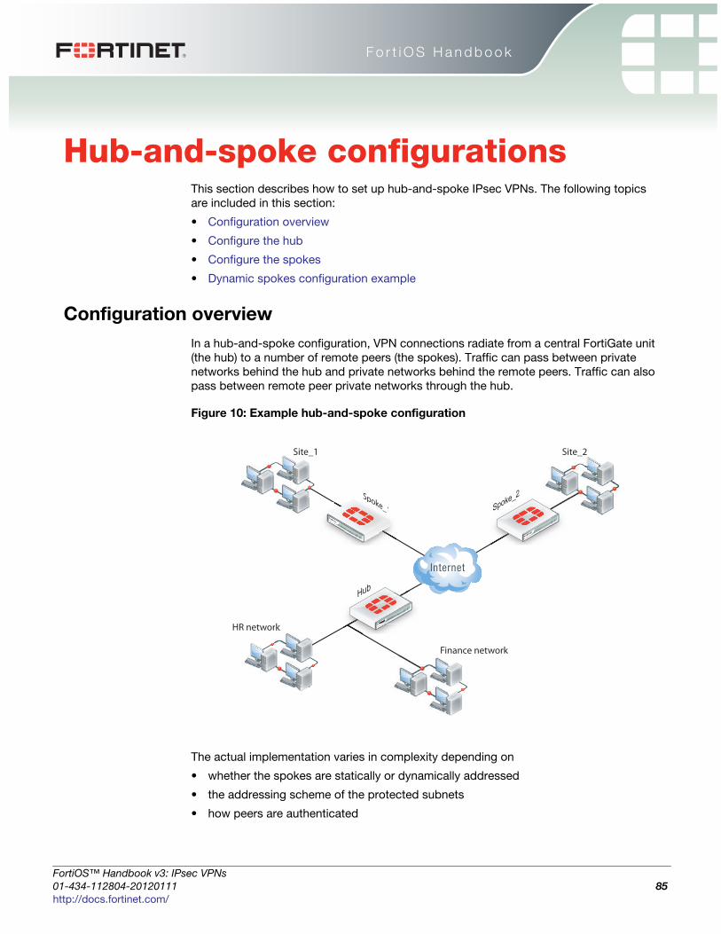
F o r t i O S H a n d b o o k
F
0
h
Hub-and-spoke configurationsThis section describes how to set up hub-and-spoke IPsec VPNs. The following topics
are included in this section:
• Configuration overview
• Configure the hub
• Configure the spokes
• Dynamic spokes configuration example
Configuration overview
In a hub-and-spoke configuration, VPN connections radiate from a central FortiGate unit
(the hub) to a number of remote peers (the spokes). Traffic can pass between private
networks behind the hub and private networks behind the remote peers. Traffic can also
pass between remote peer private networks through the hub.
Figure 10: Example hub-and-spoke configuration
The actual implementation varies in complexity depending on
• whether the spokes are statically or dynamically addressed
• the addressing scheme of the protected subnets
• how peers are authenticated
Hub
Finance network
Site_1
Hub
Spoke_1poke_1 Spoke_2
HR network
Site_2
Spok
ortiOS™ Handbook v3: IPsec VPNs
1-434-112804-20120111 85ttp://docs.fortinet.com/

Configuration overview Hub-and-spoke configurations
This guide discusses the issues involved in configuring a hub-and-spoke VPN and
provides some basic configuration examples.
Hub-and-spoke infrastructure requirements
• The FortiGate hub must be operating in NAT mode and have a static public IP
address.
• Spokes may have static IP addresses, dynamic IP addresses (see “FortiGate dialup-
client configurations” on page 133), or static domain names and dynamic IP
addresses (see “Dynamic DNS configuration” on page 101).
Spoke gateway addressing
The public IP address of the spoke is the VPN remote gateway as seen from the hub.
Statically addressed spokes each require a separate VPN phase 1 configuration on the
hub. When there are many spokes, this becomes rather cumbersome.
Using dynamic addressing for spokes simplifies the VPN configuration because then the
hub requires only a single phase 1 configuration with “dialup user” as the remote
gateway. You can use this configuration even if the remote peers have static IP
addresses. A remote peer can establish a VPN connection regardless of its IP address if
its traffic selectors match and it can authenticate to the hub. See “Dynamic spokes
configuration example” on page 95 for an example of this configuration.
Protected networks addressing
The addresses of the protected networks are needed to configure destination selectors
and sometimes for security policies and static routes. The larger the number of spokes,
the more addresses there are to manage. You can
• assign spoke subnets as part of a larger subnet, usually on a new network
or
• create address groups that contain all of the needed addresses
Using aggregated subnetsIf you are creating a new network, where subnet IP addresses are not already assigned,
you can simplify the VPN configuration by assigning spoke subnets that are part of a
large subnet.
Figure 11: Aggregated subnets
All spokes use the large subnet address, 10.1.0.0/16 for example, as
• the IPsec destination selector
• the destination of the security policy from the private subnet to the VPN (required for
policy-based VPN, optional for route-based VPN)
• the destination of the static route to the VPN (route-based)
large subnet
hub protected subnet: 10.1.0.0/24
spoke 1 protected subnet: 10.1.1.0/24
spoke 2 protected subnet: 10.1.2.0/24
spoke x protected subnet: 10.1.x.0/24
IPsec VPNs for FortiOS 4.0 MR3
86 01-434-112804-20120111
http://docs.fortinet.com/

Hub-and-spoke configurations Configure the hub
F
0
h
Each spoke uses the address of its own protected subnet as the IPsec source selector
and as the source address in its VPN security policy. The remote gateway is the public IP
address of the hub FortiGate unit.
Using an address groupIf you want to create a hub-and-spoke VPN between existing private networks, the
subnet addressing usually does not fit the aggregated subnet model discussed earlier. All
of the spokes and the hub will need to include the addresses of all the protected
networks in their configuration.
On FortiGate units, you can define a named firewall address for each of the remote
protected networks and add these addresses to a firewall address group. For a policy-
based VPN, you can then use this address group as the destination of the VPN security
policy.
For a route-based VPN, the destination of the VPN security policy can be set to All. You
need to specify appropriate routes for each of the remote subnets.
Authentication
Authentication is by a common preshared key or by certificates. For simplicity, the
examples in this chapter assume that all spokes use the same preshared key.
Configure the hub
At the FortiGate unit that acts as the hub, you need to
• configure the VPN to each spoke
• configure communication between spokes
You configure communication between spokes differently for a policy-based VPN than for
a route-based VPN. For a policy-based VPN, you configure a VPN concentrator. For a
route-based VPN, you must either define security policies or group the IPsec interfaces
into a zone
Define the hub-spoke VPNs
Perform these steps at the FortiGate unit that will act as the hub. Although this procedure
assumes that the spokes are all FortiGate units, a spoke could also be VPN client
software, such as FortiClient Endpoint Security.
ortiOS™ Handbook v3: IPsec VPNs
1-434-112804-20120111 87ttp://docs.fortinet.com/
Configure the hub Hub-and-spoke configurations
To configure the VPN hub
1 At the hub, define the phase 1 configuration for each spoke. See “Auto Key phase 1
parameters” on page 39. Enter these settings in particular:
2 Define the phase 2 parameters needed to create a VPN tunnel with each spoke. See
“Phase 2 parameters” on page 57. Enter these settings in particular:
Define the hub-spoke security policies
1 Define a name for the address of the private network behind the hub. For more
information, see “Defining policy addresses” on page 63.
2 Define names for the addresses or address ranges of the private networks behind the
spokes. For more information, see “Defining policy addresses” on page 63.
3 Define the VPN concentrator. See “To define the VPN concentrator” on page 90.
NameEnter a name to identify the VPN in phase 2 configurations,
security policies and the VPN monitor.
Remote
Gateway
The remote gateway is the other end of the VPN tunnel. There are
three options:
Static IP Address — Enter the spoke’s public IP Address. You will
need to create a phase 1 configuration for each spoke. Either the
hub or the spoke can establish the VPN connection.
Dialup User — No additional information is needed. The hub
accepts connections from peers with appropriate encryption and
authentication settings. Only one phase 1 configuration is needed
for multiple dialup spokes. Only the spoke can establish the VPN
tunnel.
Dynamic DNS — If the spoke subscribes to a dynamic DNS
service, enter the spoke’s Dynamic DNS domain name. Either the
hub or the spoke can establish the VPN connection. For more
information, see “Dynamic DNS configuration” on page 101.
Local Interface
Select the FortiGate interface that connects to the remote
gateway. This is usually the FortiGate unit’s public interface.
This interface cannot be a loopback interface.
Enable IPsec
Interface Mode
You must select Advanced to see this setting. If IPsec Interface
Mode is enabled, the FortiGate unit creates a virtual IPsec
interface for a route-based VPN. Disable this option if you want to
create a policy-based VPN. For more information, see “Comparing
policy-based or route-based VPNs” on page 22.
After you select OK to create the phase 1 configuration, you
cannot change this setting.
Name Enter a name to identify this spoke phase 2 configuration.
Phase 1Select the name of the phase 1 configuration that you defined for
this spoke.
IPsec VPNs for FortiOS 4.0 MR3
88 01-434-112804-20120111
http://docs.fortinet.com/
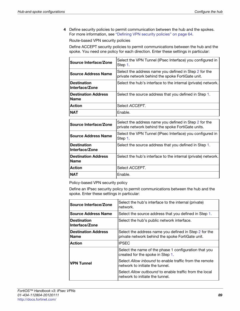
Hub-and-spoke configurations Configure the hub
F
0
h
4 Define security policies to permit communication between the hub and the spokes.
For more information, see “Defining VPN security policies” on page 64.
Route-based VPN security policies
Define ACCEPT security policies to permit communications between the hub and the
spoke. You need one policy for each direction. Enter these settings in particular:
Policy-based VPN security policy
Define an IPsec security policy to permit communications between the hub and the
spoke. Enter these settings in particular:
Source Interface/ZoneSelect the VPN Tunnel (IPsec Interface) you configured in
Step 1.
Source Address NameSelect the address name you defined in Step 2 for the
private network behind the spoke FortiGate unit.
Destination
Interface/Zone
Select the hub’s interface to the internal (private) network.
Destination Address
Name
Select the source address that you defined in Step 1.
Action Select ACCEPT.
NAT Enable.
Source Interface/ZoneSelect the address name you defined in Step 2 for the
private network behind the spoke FortiGate units.
Source Address NameSelect the VPN Tunnel (IPsec Interface) you configured in
Step 1.
Destination
Interface/Zone
Select the source address that you defined in Step 1.
Destination Address
Name
Select the hub’s interface to the internal (private) network.
Action Select ACCEPT.
NAT Enable.
Source Interface/ZoneSelect the hub’s interface to the internal (private)
network.
Source Address Name Select the source address that you defined in Step 1.
Destination
Interface/Zone
Select the hub’s public network interface.
Destination Address
Name
Select the address name you defined in Step 2 for the
private network behind the spoke FortiGate unit.
Action IPSEC
VPN Tunnel
Select the name of the phase 1 configuration that you
created for the spoke in Step 1.
Select Allow inbound to enable traffic from the remote
network to initiate the tunnel.
Select Allow outbound to enable traffic from the local
network to initiate the tunnel.
ortiOS™ Handbook v3: IPsec VPNs
1-434-112804-20120111 89ttp://docs.fortinet.com/

Configure the hub Hub-and-spoke configurations
5 In the policy list, arrange the policies in the following order:
• IPsec policies that control traffic between the hub and the spokes first
• the default security policy last
Configuring communication between spokes (policy-based VPN)
For a policy-based hub-and-spoke VPN, you define a concentrator to enable
communication between the spokes.
To define the VPN concentrator
1 At the hub, go to VPN > IPSEC > Concentrator and select Create New.
2 In the Concentrator Name field, type a name to identify the concentrator.
3 From the Available Tunnels list, select a VPN tunnel and then select the right-pointing
arrow.
4 Repeat Step 3 until all of the tunnels associated with the spokes are included in the
concentrator.
5 Select OK.
Configuring communication between spokes (route-based VPN)
For a route-based hub-and-spoke VPN, there are several ways you can enable
communication between the spokes:
• put all of the IPsec interfaces into a zone and enable intra-zone traffic. This eliminates
the need for any security policy for the VPN, but you cannot apply UTM features to
scan the traffic for security threats.
• put all of the IPsec interfaces into a zone and create a single zone-to-zone security
policy
• create a security policy for each pair of spokes that are allowed to communicate with
each other. The number of policies required increases rapidly as the number of spokes
increases.
Using a zone as a concentratorA simple way to provide communication among all of the spokes is to create a zone and
allow intra-zone communication. You cannot apply UTM features using this method.
1 Go to System > Network > Interface.
2 Select the down-arrow on the Create New button and select Zone.
3 In the Zone Name field, enter a name, such as Our_VPN_zone.
4 Clear Block intra-zone traffic.
5 In the Interface Members list, select the IPsec interfaces that are part of your VPN.
6 Select OK.
To remove tunnels from the VPN concentrator, select the tunnel in the Members list and
select the left-pointing arrow.
IPsec VPNs for FortiOS 4.0 MR3
90 01-434-112804-20120111
http://docs.fortinet.com/

Hub-and-spoke configurations Configure the hub
F
0
h
Using a zone with a policy as a concentratorIf you put all of the hub IPsec interfaces involved in the VPN into a zone, you can enable
communication among all of the spokes and apply UTM features with just one security
policy.
To create a zone for the VPN
1 Go to System > Network > Interface.
2 Select the down-arrow on the Create New button and select Zone.
3 In the Zone Name field, enter a name, such as Our_VPN_zone.
4 Select Block intra-zone traffic.
5 In the Interface Members list, select the IPsec interfaces that are part of your VPN.
6 Select OK.
To create a security policy for the zone
1 Go to Policy > Policy > Policy. Select Create New and enter the settings:
2 Select OK.
Using security policies as a concentratorTo enable communication between two spokes, you need to define an ACCEPT security
policy for them. To allow either spoke to initiate communication, you must create a policy
for each direction. This procedure describes a security policy for communication from
Spoke 1 to Spoke 2. Others are similar.
1 Define names for the addresses or address ranges of the private networks behind
each spoke. For more information, see “Defining policy addresses” on page 63.
2 Go to Policy > Policy > Policy. Select Create New and enter the settings:
Source Interface/Zone Select the zone you created for your VPN.
Source Address Name Select All.
Destination Interface/Zone Select the zone you created for your VPN.
Destination Address Name Select All.
Action Select ACCEPT.
NAT Enable.
UTMIf you want to apply UTM features to this traffic, select
the appropriate profiles.
Source Interface/Zone Select the IPsec interface that connects to Spoke 1.
Source Address NameSelect the address of the private network behind
Spoke 1.
Destination Interface/Zone Select the IPsec interface that connects to Spoke 2.
Destination Address NameSelect the address of the private network behind
Spoke 2.
Action Select ACCEPT.
ortiOS™ Handbook v3: IPsec VPNs
1-434-112804-20120111 91ttp://docs.fortinet.com/

Configure the spokes Hub-and-spoke configurations
3 Select OK.
Configure the spokes
Although this procedure assumes that the spokes are all FortiGate units, a spoke could
also be VPN client software, such as FortiClient Endpoint Security.
Perform these steps at each FortiGate unit that will act as a spoke.
To create the phase 1 and phase_2 configurations
1 At the spoke, define the phase 1 parameters that the spoke will use to establish a
secure connection with the hub. See “Auto Key phase 1 parameters” on page 39.
Enter these settings:
2 Create the phase 2 tunnel definition. See “Phase 2 parameters” on page 57. Select
the set of phase 1 parameters that you defined for the hub. You can select the name
of the hub from the Static IP Address part of the list.
Configuring security policies for hub-to-spoke communication
1 Create an address for this spoke. See “Defining policy addresses” on page 63. Enter
the IP address and netmask of the private network behind the spoke.
2 Create an address to represent the hub. See “Defining policy addresses” on page 63.
Enter the IP address and netmask of the private network behind the hub.
3 Define the security policy to enable communication with the hub.
Route-based VPN security policy
Define two security policies to permit communications to and from the hub. Enter
these settings:
NAT Enable.
UTMIf you want to apply UTM features to this traffic, select
the appropriate profiles.
Remote Gateway Select Static IP Address.
IP AddressType the IP address of the interface that connects to the
hub.
Enable IPsec
Interface Mode
Enable if you are creating a route-based VPN.
Clear if you are creating a policy-based VPN.
Source Interface/Zone Select the virtual IPsec interface you created.
Source Address Name Select the hub address you defined in Step 1.
Destination
Interface/Zone
Select the spoke’s interface to the internal (private)
network.
Destination Address
Name
Select the spoke addresses you defined in Step 2.
Action Select ACCEPT
NAT Enable
IPsec VPNs for FortiOS 4.0 MR3
92 01-434-112804-20120111
http://docs.fortinet.com/
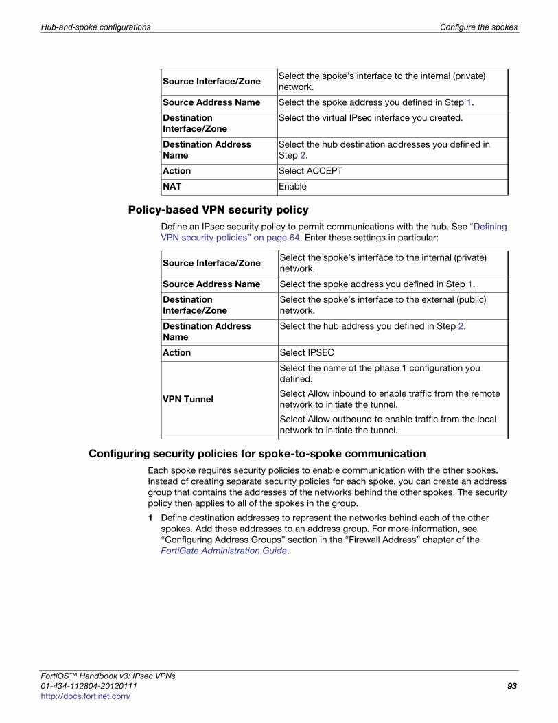
Hub-and-spoke configurations Configure the spokes
F
0
h
Policy-based VPN security policyDefine an IPsec security policy to permit communications with the hub. See “Defining
VPN security policies” on page 64. Enter these settings in particular:
Configuring security policies for spoke-to-spoke communication
Each spoke requires security policies to enable communication with the other spokes.
Instead of creating separate security policies for each spoke, you can create an address
group that contains the addresses of the networks behind the other spokes. The security
policy then applies to all of the spokes in the group.
1 Define destination addresses to represent the networks behind each of the other
spokes. Add these addresses to an address group. For more information, see
“Configuring Address Groups” section in the “Firewall Address” chapter of the
FortiGate Administration Guide.
Source Interface/ZoneSelect the spoke’s interface to the internal (private)
network.
Source Address Name Select the spoke address you defined in Step 1.
Destination
Interface/Zone
Select the virtual IPsec interface you created.
Destination Address
Name
Select the hub destination addresses you defined in
Step 2.
Action Select ACCEPT
NAT Enable
Source Interface/ZoneSelect the spoke’s interface to the internal (private)
network.
Source Address Name Select the spoke address you defined in Step 1.
Destination
Interface/Zone
Select the spoke’s interface to the external (public)
network.
Destination Address
Name
Select the hub address you defined in Step 2.
Action Select IPSEC
VPN Tunnel
Select the name of the phase 1 configuration you
defined.
Select Allow inbound to enable traffic from the remote
network to initiate the tunnel.
Select Allow outbound to enable traffic from the local
network to initiate the tunnel.
ortiOS™ Handbook v3: IPsec VPNs
1-434-112804-20120111 93ttp://docs.fortinet.com/
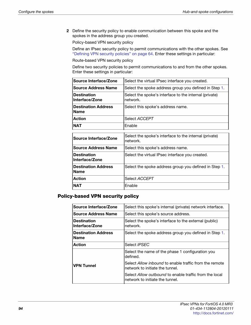
Configure the spokes Hub-and-spoke configurations
2 Define the security policy to enable communication between this spoke and the
spokes in the address group you created.
Policy-based VPN security policy
Define an IPsec security policy to permit communications with the other spokes. See
“Defining VPN security policies” on page 64. Enter these settings in particular:
Route-based VPN security policy
Define two security policies to permit communications to and from the other spokes.
Enter these settings in particular:
Policy-based VPN security policy
Source Interface/Zone Select the virtual IPsec interface you created.
Source Address Name Select the spoke address group you defined in Step 1.
Destination
Interface/Zone
Select the spoke’s interface to the internal (private)
network.
Destination Address
Name
Select this spoke’s address name.
Action Select ACCEPT
NAT Enable
Source Interface/ZoneSelect the spoke’s interface to the internal (private)
network.
Source Address Name Select this spoke’s address name.
Destination
Interface/Zone
Select the virtual IPsec interface you created.
Destination Address
Name
Select the spoke address group you defined in Step 1.
Action Select ACCEPT
NAT Enable
Source Interface/Zone Select this spoke’s internal (private) network interface.
Source Address Name Select this spoke’s source address.
Destination
Interface/Zone
Select the spoke’s interface to the external (public)
network.
Destination Address
Name
Select the spoke address group you defined in Step 1.
Action Select IPSEC
VPN Tunnel
Select the name of the phase 1 configuration you
defined.
Select Allow inbound to enable traffic from the remote
network to initiate the tunnel.
Select Allow outbound to enable traffic from the local
network to initiate the tunnel.
IPsec VPNs for FortiOS 4.0 MR3
94 01-434-112804-20120111
http://docs.fortinet.com/
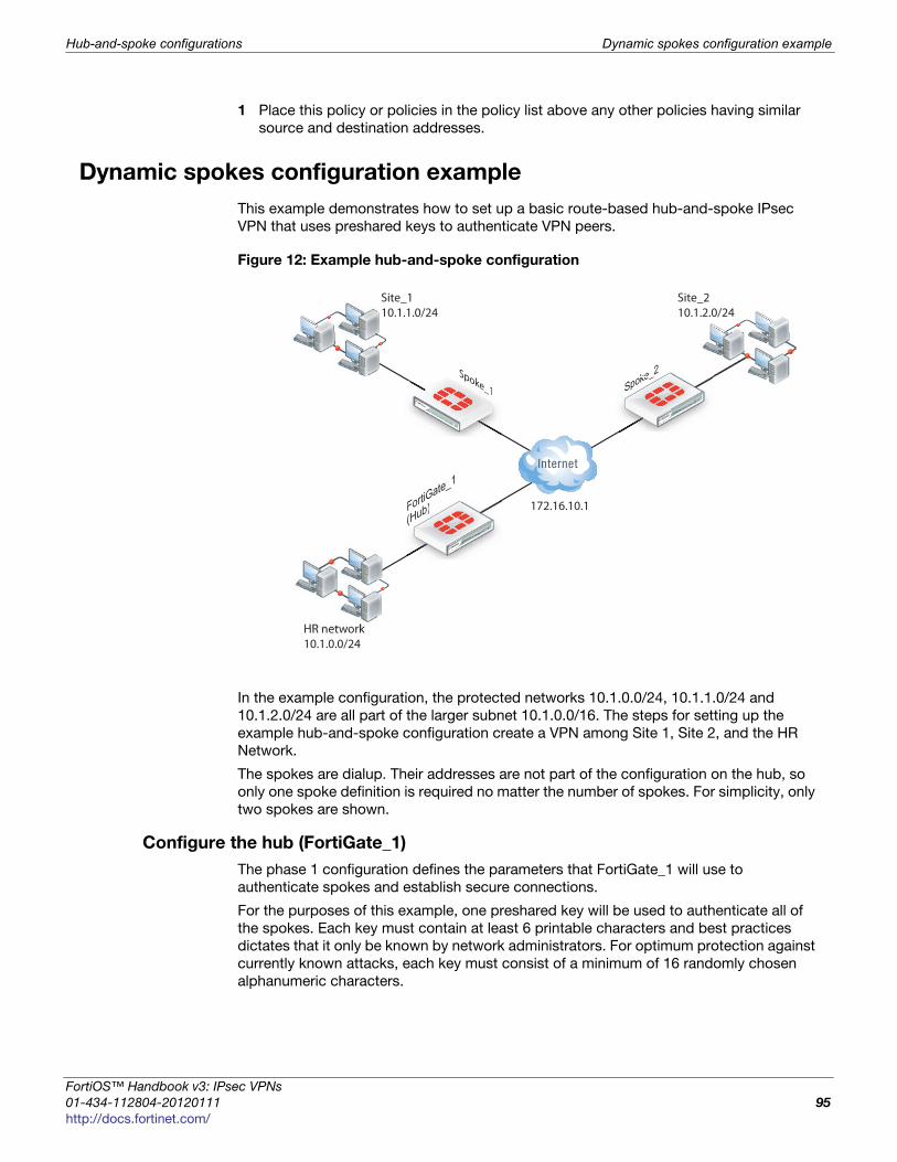
Hub-and-spoke configurations Dynamic spokes configuration example
F
0
h
1 Place this policy or policies in the policy list above any other policies having similar
source and destination addresses.
Dynamic spokes configuration example
This example demonstrates how to set up a basic route-based hub-and-spoke IPsec
VPN that uses preshared keys to authenticate VPN peers.
Figure 12: Example hub-and-spoke configuration
In the example configuration, the protected networks 10.1.0.0/24, 10.1.1.0/24 and
10.1.2.0/24 are all part of the larger subnet 10.1.0.0/16. The steps for setting up the
example hub-and-spoke configuration create a VPN among Site 1, Site 2, and the HR
Network.
The spokes are dialup. Their addresses are not part of the configuration on the hub, so
only one spoke definition is required no matter the number of spokes. For simplicity, only
two spokes are shown.
Configure the hub (FortiGate_1)
The phase 1 configuration defines the parameters that FortiGate_1 will use to
authenticate spokes and establish secure connections.
For the purposes of this example, one preshared key will be used to authenticate all of
the spokes. Each key must contain at least 6 printable characters and best practices
dictates that it only be known by network administrators. For optimum protection against
currently known attacks, each key must consist of a minimum of 16 randomly chosen
alphanumeric characters.
FortiGate_1
(Hub)
Site_110.1.1.0/24
Fo(Hub)
Spoke_1poke_1 Spoke_2
HR network10.1.0.0/24
Site_210.1.2.0/24
172.16.10.1
Spoke_
ortiOS™ Handbook v3: IPsec VPNs
1-434-112804-20120111 95ttp://docs.fortinet.com/

Dynamic spokes configuration example Hub-and-spoke configurations
Define the IPsec configuration
To define the phase 1 parameters
1 At FortiGate_1, go to VPN > IPsec > Auto Key (IKE).
2 Define the phase 1 parameters that the hub will use to establish a secure connection
to the spokes. Select Create Phase 1, enter the following information, and select OK:
The basic phase 2 settings associate IPsec phase 2 parameters with the phase 1
configuration and specify the remote end points of the VPN tunnels.
To define the phase 2 parameters
1 Go to VPN > IPsec > Auto Key (IKE).
2 Create a phase 2 tunnel definition for the spokes. Select Create Phase 2, enter the
following information, and select OK:
Define the security policiessecurity policies control all IP traffic passing between a source address and a destination
address. For a route-based VPN, the policies are simpler than for a policy-based VPN.
Instead of an IPSEC policy, you use an ACCEPT policy with the virtual IPsec interface as
the external interface.
Before you define security policies, you must first define firewall addresses to use in
those policies. You need addresses for:
• the HR network behind FortiGate_1
• the aggregate subnet address for the protected networks
To define the IP address of the HR network behind FortiGate_1
1 Go to Firewall Objects > Address > Address.
2 Select Create New, enter the following information, and select OK:
Name Type a name (for example, toSpokes).
Remote Gateway Dialup user
Local Interface External
Mode Main
Authentication Method Preshared Key
Pre-shared Key Enter the preshared key.
Peer Options Accept any peer ID
Name Enter a name for the phase 2 definition (for example, toSpokes_ph2).
Phase 1Select the Phase 1 configuration that you defined previously (for
example, toSpokes).
Address Name Enter an address name (for example, HR_Network).
Subnet/IP RangeEnter the IP address of the HR network behind FortiGate_1
(for example, 10.1.0.0/24).
IPsec VPNs for FortiOS 4.0 MR3
96 01-434-112804-20120111
http://docs.fortinet.com/
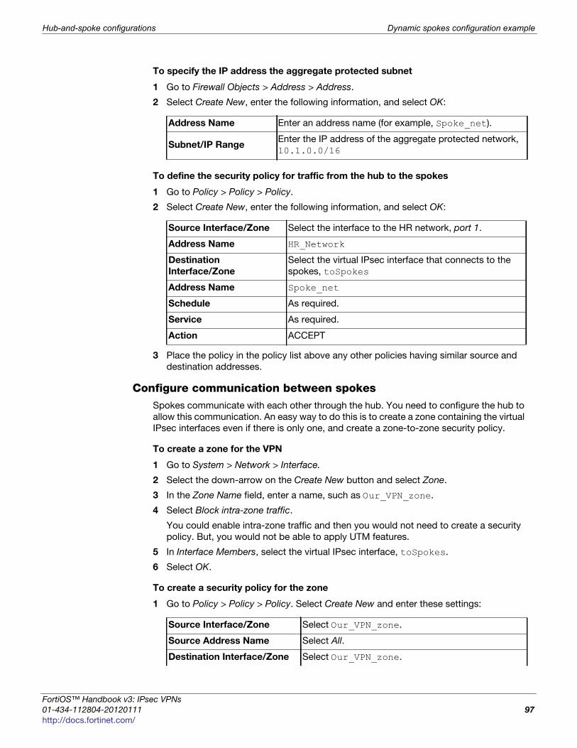
Hub-and-spoke configurations Dynamic spokes configuration example
F
0
h
To specify the IP address the aggregate protected subnet
1 Go to Firewall Objects > Address > Address.
2 Select Create New, enter the following information, and select OK:
To define the security policy for traffic from the hub to the spokes
1 Go to Policy > Policy > Policy.
2 Select Create New, enter the following information, and select OK:
3 Place the policy in the policy list above any other policies having similar source and
destination addresses.
Configure communication between spokesSpokes communicate with each other through the hub. You need to configure the hub to
allow this communication. An easy way to do this is to create a zone containing the virtual
IPsec interfaces even if there is only one, and create a zone-to-zone security policy.
To create a zone for the VPN
1 Go to System > Network > Interface.
2 Select the down-arrow on the Create New button and select Zone.
3 In the Zone Name field, enter a name, such as Our_VPN_zone.
4 Select Block intra-zone traffic.
You could enable intra-zone traffic and then you would not need to create a security
policy. But, you would not be able to apply UTM features.
5 In Interface Members, select the virtual IPsec interface, toSpokes.
6 Select OK.
To create a security policy for the zone
1 Go to Policy > Policy > Policy. Select Create New and enter these settings:
Address Name Enter an address name (for example, Spoke_net).
Subnet/IP RangeEnter the IP address of the aggregate protected network,
10.1.0.0/16
Source Interface/Zone Select the interface to the HR network, port 1.
Address Name HR_Network
Destination
Interface/Zone
Select the virtual IPsec interface that connects to the
spokes, toSpokes
Address Name Spoke_net
Schedule As required.
Service As required.
Action ACCEPT
Source Interface/Zone Select Our_VPN_zone.
Source Address Name Select All.
Destination Interface/Zone Select Our_VPN_zone.
ortiOS™ Handbook v3: IPsec VPNs
1-434-112804-20120111 97ttp://docs.fortinet.com/
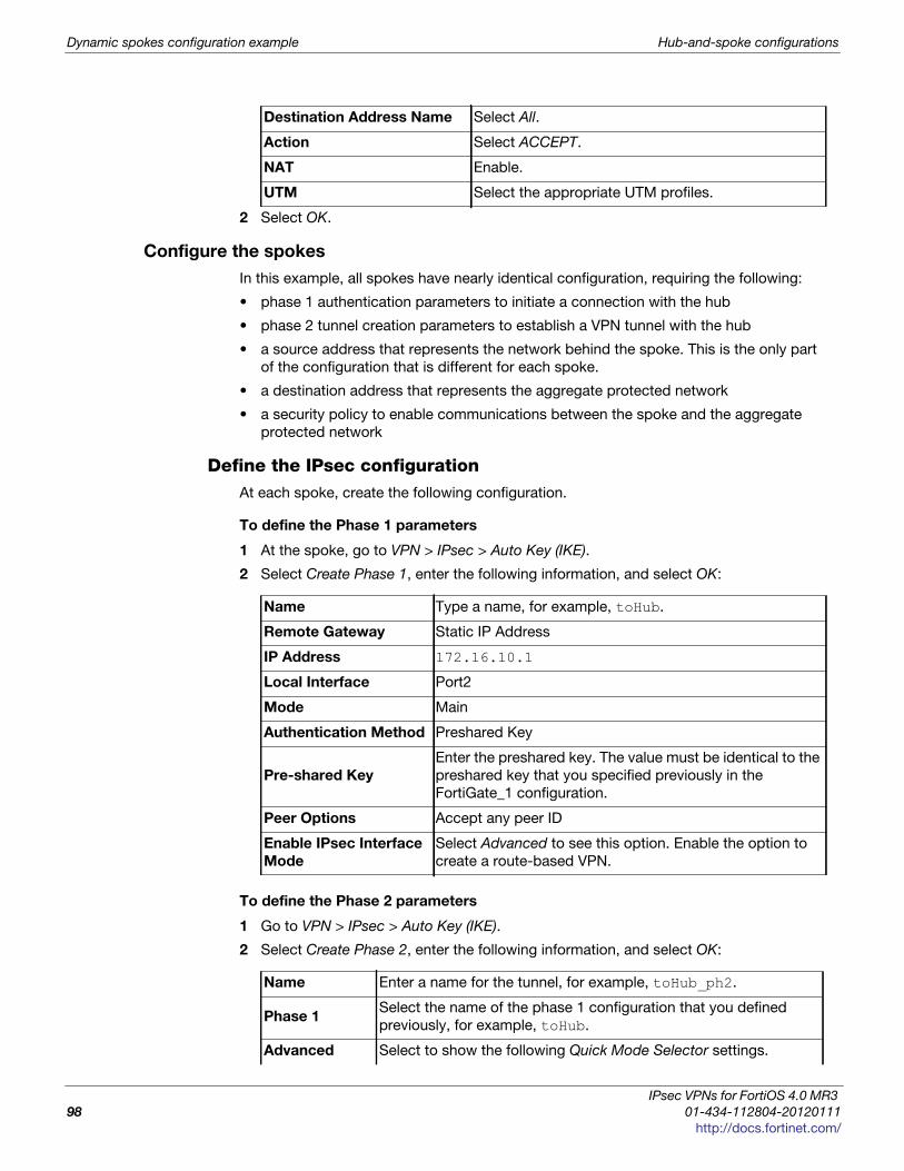
Dynamic spokes configuration example Hub-and-spoke configurations
2 Select OK.
Configure the spokes
In this example, all spokes have nearly identical configuration, requiring the following:
• phase 1 authentication parameters to initiate a connection with the hub
• phase 2 tunnel creation parameters to establish a VPN tunnel with the hub
• a source address that represents the network behind the spoke. This is the only part
of the configuration that is different for each spoke.
• a destination address that represents the aggregate protected network
• a security policy to enable communications between the spoke and the aggregate
protected network
Define the IPsec configurationAt each spoke, create the following configuration.
To define the Phase 1 parameters
1 At the spoke, go to VPN > IPsec > Auto Key (IKE).
2 Select Create Phase 1, enter the following information, and select OK:
To define the Phase 2 parameters
1 Go to VPN > IPsec > Auto Key (IKE).
2 Select Create Phase 2, enter the following information, and select OK:
Destination Address Name Select All.
Action Select ACCEPT.
NAT Enable.
UTM Select the appropriate UTM profiles.
Name Type a name, for example, toHub.
Remote Gateway Static IP Address
IP Address 172.16.10.1
Local Interface Port2
Mode Main
Authentication Method Preshared Key
Pre-shared Key
Enter the preshared key. The value must be identical to the
preshared key that you specified previously in the
FortiGate_1 configuration.
Peer Options Accept any peer ID
Enable IPsec Interface
Mode
Select Advanced to see this option. Enable the option to
create a route-based VPN.
Name Enter a name for the tunnel, for example, toHub_ph2.
Phase 1Select the name of the phase 1 configuration that you defined
previously, for example, toHub.
Advanced Select to show the following Quick Mode Selector settings.
IPsec VPNs for FortiOS 4.0 MR3
98 01-434-112804-20120111
http://docs.fortinet.com/
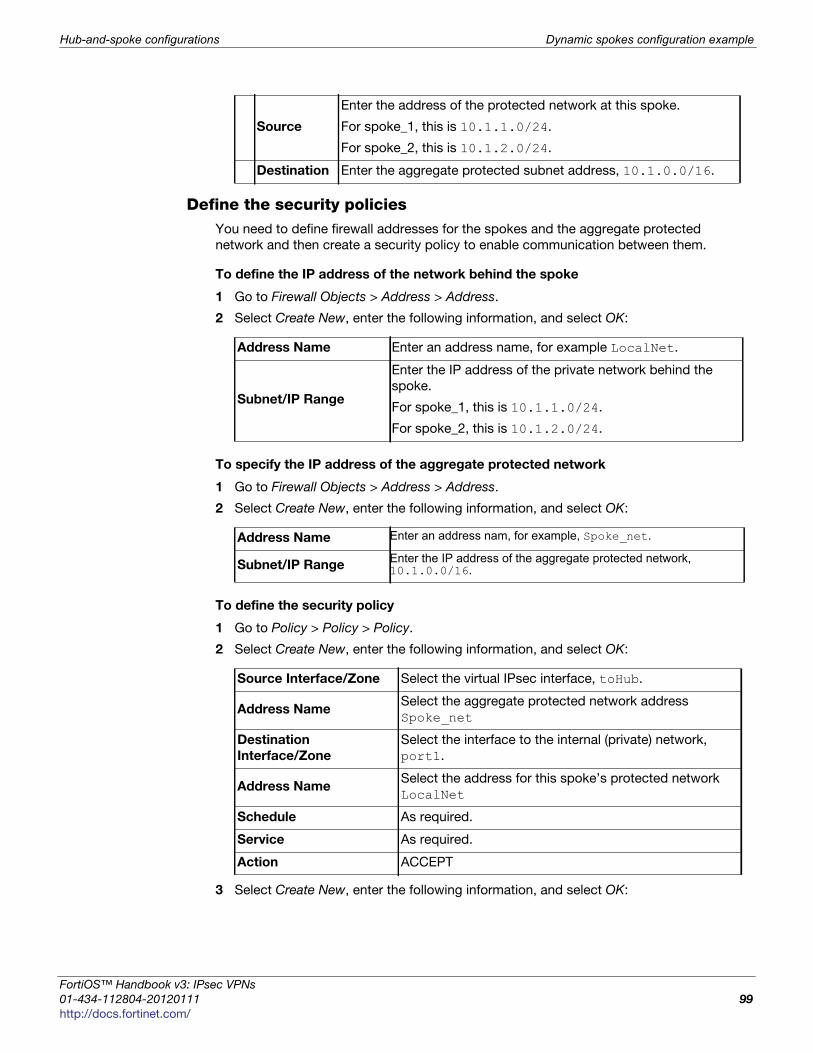
Hub-and-spoke configurations Dynamic spokes configuration example
F
0
h
Define the security policiesYou need to define firewall addresses for the spokes and the aggregate protected
network and then create a security policy to enable communication between them.
To define the IP address of the network behind the spoke
1 Go to Firewall Objects > Address > Address.
2 Select Create New, enter the following information, and select OK:
To specify the IP address of the aggregate protected network
1 Go to Firewall Objects > Address > Address.
2 Select Create New, enter the following information, and select OK:
To define the security policy
1 Go to Policy > Policy > Policy.
2 Select Create New, enter the following information, and select OK:
3 Select Create New, enter the following information, and select OK:
Source
Enter the address of the protected network at this spoke.
For spoke_1, this is 10.1.1.0/24.
For spoke_2, this is 10.1.2.0/24.
Destination Enter the aggregate protected subnet address, 10.1.0.0/16.
Address Name Enter an address name, for example LocalNet.
Subnet/IP Range
Enter the IP address of the private network behind the
spoke.
For spoke_1, this is 10.1.1.0/24.
For spoke_2, this is 10.1.2.0/24.
Address Name Enter an address nam, for example, Spoke_net.
Subnet/IP RangeEnter the IP address of the aggregate protected network, 10.1.0.0/16.
Source Interface/Zone Select the virtual IPsec interface, toHub.
Address NameSelect the aggregate protected network address
Spoke_net
Destination
Interface/Zone
Select the interface to the internal (private) network,
port1.
Address NameSelect the address for this spoke’s protected network
LocalNet
Schedule As required.
Service As required.
Action ACCEPT
ortiOS™ Handbook v3: IPsec VPNs
1-434-112804-20120111 99ttp://docs.fortinet.com/
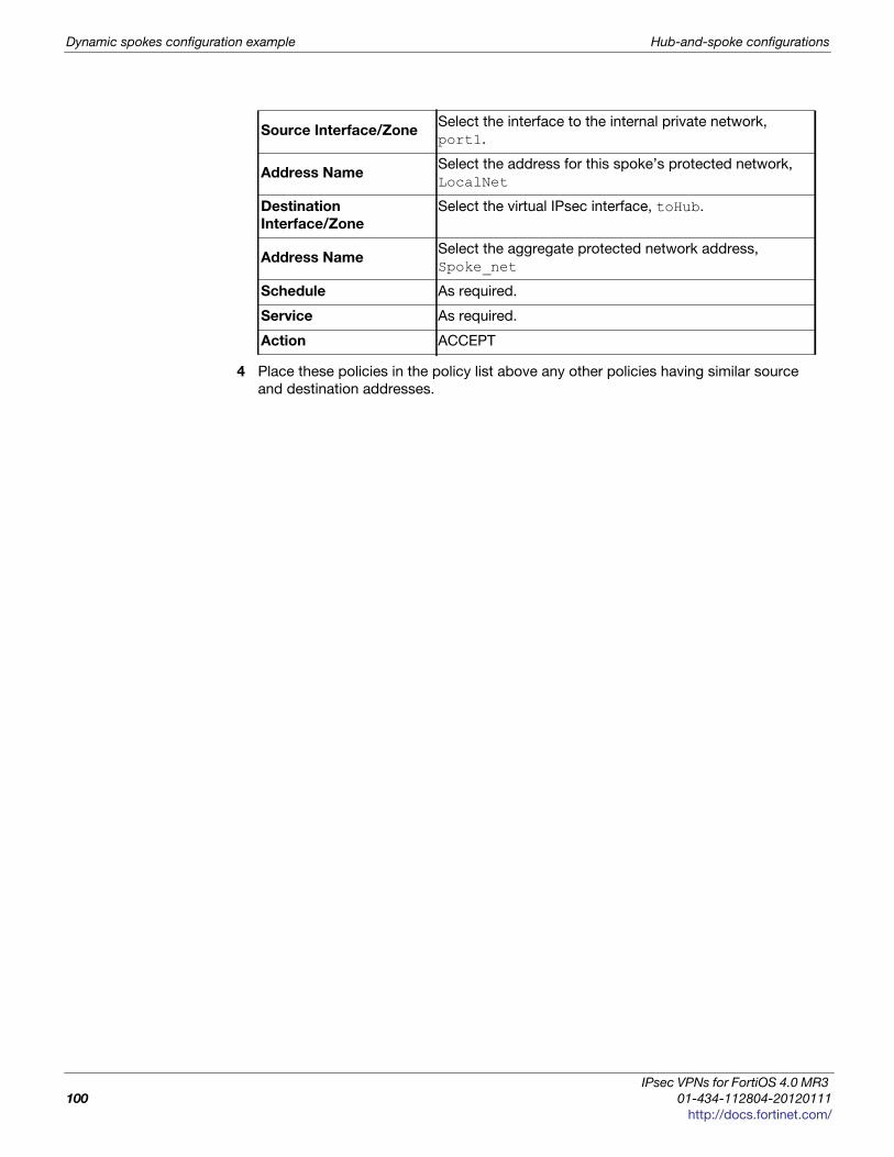
Dynamic spokes configuration example Hub-and-spoke configurations
4 Place these policies in the policy list above any other policies having similar source
and destination addresses.
Source Interface/ZoneSelect the interface to the internal private network,
port1.
Address NameSelect the address for this spoke’s protected network,
LocalNet
Destination
Interface/Zone
Select the virtual IPsec interface, toHub.
Address NameSelect the aggregate protected network address,
Spoke_net
Schedule As required.
Service As required.
Action ACCEPT
IPsec VPNs for FortiOS 4.0 MR3
100 01-434-112804-20120111
http://docs.fortinet.com/

F o r t i O S H a n d b o o k
F
0
h
Dynamic DNS configurationThis section describes how to configure a site-to-site VPN, in which one FortiGate unit
has a static IP address and the other FortiGate unit has a domain name and a dynamic IP
address.
The following topics are included in this section:
• Dynamic DNS over VPN concepts
• Dynamic DNS topology
• General configuration steps
• Configure the dynamically-addressed VPN peer
• Configure the fixed-address VPN peer
• Testing
Dynamic DNS over VPN concepts
A typical computer has a static IP address and one or more DNS servers to resolve fully
qualified domain names (FQDN) into IP addresses. A domain name assigned to this
computer is resolved by any DNS server having an entry for the domain name and its
static IP address. The IP address never changes or changes only rarely so the DNS
server can reliably say it has the correct address for that domain all the time.
Dynamic DNS (DDNS)
It is different when a computer has a dynamic IP address, such as an IP address
assigned dynamically by a DHCP server, and a domain name. Computers that want to
contact this computer do not know what its current IP address is. To solve this problem
there are dynamic DNS servers. These are public servers that store a DNS entry for your
computer that includes its current IP address and associated domain name. These
entries are kept up to date by your computer sending its current IP address to the
dynamic DNS (DDNS) server to ensure its entry is always up to date. When other
computers want to contact your domain, their DNS gets your IP address from your DDNS
server. To use DDNS servers, you must subscribe to them and usually pay for their
services.
When configuring DDNS on your FortiGate unit, go to System > Network > DNS and
enable Use DDNS. Then select the interface with the dynamic connection, which DDNS
server you have an account with, your domain name, and account information. If your
DDNS server is not on the list, there is a generic option where you can provide your
DDNS server information.
RoutingWhen an interface has some form of changing IP address (DDNS, PPPoE, or DHCP
assigned address), routing needs special attention. The standard static route cannot
handle the changing IP address. The solution is to use the dynamic-gateway command in
the CLI. Say for example you already have four static routes, and you have a PPPoE
connection over the wan2 interface and you want to use that as your default route.
ortiOS™ Handbook v3: IPsec VPNs
1-434-112804-20120111 101ttp://docs.fortinet.com/

Dynamic DNS over VPN concepts Dynamic DNS configuration
The route is configured on the dynamic address VPN peer trying to access the static
address FortiGate unit.
To configure dynamic gateway routing - CLI
config router staticedit 5set dst 0.0.0.0 0.0.0.0set dynamic-gateway enableset device wan2
nextend
For more information on DDNS, see the System Administration guide.
Dynamic DNS over VPN
IPsec VPN expects an IP address for each end of the VPN tunnel. All configuration and
communication with that tunnel depends on the IP addresses as reference points.
However, when the interface the tunnel is on has DDNS enabled there is no set IP
address. The remote end of the VPN tunnel now needs another way to reference your end
of the VPN tunnel. This is accomplished using Local ID.
A FortiGate unit that has a domain name and a dynamic IP address can initiate VPN
connections anytime—the remote peer can reply to the local FortiGate unit using the
source IP address that was sent in the packet header because it is current. Without doing
a DNS lookup first, the remote peer runs the risk of the dynamic IP changing before it
attempts to connect. To avoid this, the remote peer must perform a DNS lookup for the
domain name of to be sure of the dynamic IP address before initiating the connection.
Remote GatewayWhen configuring the Phase 1 entry for a VPN tunnel, the Remote Gateway determines
the addressing method the remote end of the tunnel uses as one of Static IP Address,
Dialup User, or Dynamic DNS. There are different fields for each option.
When you select the Dynamic DNS VPN type there is a related field called Dynamic DNS.
The Dynamic DNS field is asking for the FQDN of the remote end of the tunnel. It uses
this information to look up the IP address of the remote end of the tunnel through the
DDNS server associated with that domain name.
Local ID (peer ID)The Local ID or peer ID can be used to uniquely identify one end of a VPN tunnel. This
enables a more secure connection. Also if you have multiple VPN tunnels negotiating, this
ensures the proper remote and local ends connect. When you configure it on your end, it
is your Local ID. When the remote end connects to you, they see it as your peer ID.
If you are debugging a VPN connection, the Local ID is part of the VPN negotiations. You
can use it to help troubleshoot connection problems.
To configure your Local ID
1 Go to VPN > IPsec > Auto Key (IKE).
2 Select Create New Phase 1 or edit an existing Phase 1 entry.
3 Select Advanced.
4 In the P1 Proposal section, enter your Local ID.
5 Select OK.
IPsec VPNs for FortiOS 4.0 MR3
102 01-434-112804-20120111
http://docs.fortinet.com/

Dynamic DNS configuration Dynamic DNS topology
F
0
h
The default configuration is to accept all local IDs (peer IDs). If you have the Local ID set,
the remote end of the tunnel must be configured to accept your Local ID.
To accept a specific Peer ID
1 Go to VPN > IPsec > Auto Key (IKE).
2 Select Create New Phase 1.
3 Select Aggressive mode.
4 For Peer Options, select Accept this peer ID. This option becomes visible only when
Aggressive mode is selected.
5 Enter the string the other end of the tunnel used for its Local ID.
6 Configure the rest of the Phase 1 entry as required.
7 Select OK.
Route-based or policy-based VPNVPN over dynamic DNS can be configured with either route-based or policy-based VPN
settings. Both are valid, but have differences in configuration. Choose the best method
based on your requirements. For more information on route-based and policy-based, see
“Types of VPNs” on page 21.
Route-based VPN configuration requires two security policies to be configured (one for
each direction of traffic) to permit traffic over the VPN virtual interface, and you must also
add a static route entry for that VPN interface or the VPN traffic will not reach its
destination. See “Creating branch_2 route-based security policies” on page 107 and
“Creating branch_1 route-based security policies” on page 112.
Policy-based VPN configuration uses more complex and often more IPsec security
policies, but does not require a static route entry. It has the benefit of being able to
configure multiple policies for handling multiple protocols in different ways, such as more
scanning of less secure protocols or guaranteeing a minimum bandwidth for protocols
such as VoIP. See “Creating branch_2 policy-based security policies” on page 109 and
“Creating branch_1 policy-based security policies” on page 113
Dynamic DNS topology
In this scenario, two branch offices each have a FortiGate unit and are connected in a
gateway-to-gateway VPN configuration. One FortiGate unit has a domain name
(example.com) with a dynamic IP address. See branch_2 in Figure 13.
Whenever the branch_2 unit connects to the Internet (and possibly also at predefined
intervals set by the ISP), the ISP may assign a different IP address to the FortiGate unit.
The unit has its domain name registered with a dynamic DNS service. The branch_2 unit
checks in with the DDNS server on a regular basis, and that server provides the DNS
information for the domain name, updating the IP address from time to time. Remote
peers have to locate the branch_2 FortiGate unit through a DNS lookup each time to
ensure the address they get is current and correct.
ortiOS™ Handbook v3: IPsec VPNs
1-434-112804-20120111 103ttp://docs.fortinet.com/
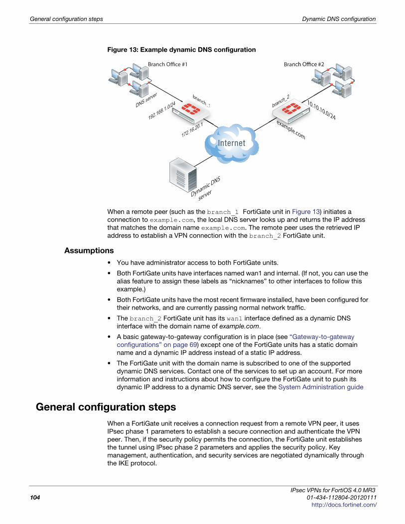
General configuration steps Dynamic DNS configuration
Figure 13: Example dynamic DNS configuration
When a remote peer (such as the branch_1 FortiGate unit in Figure 13) initiates a
connection to example.com, the local DNS server looks up and returns the IP address
that matches the domain name example.com. The remote peer uses the retrieved IP
address to establish a VPN connection with the branch_2 FortiGate unit.
Assumptions
• You have administrator access to both FortiGate units.
• Both FortiGate units have interfaces named wan1 and internal. (If not, you can use the
alias feature to assign these labels as “nicknames” to other interfaces to follow this
example.)
• Both FortiGate units have the most recent firmware installed, have been configured for
their networks, and are currently passing normal network traffic.
• The branch_2 FortiGate unit has its wan1 interface defined as a dynamic DNS
interface with the domain name of example.com.
• A basic gateway-to-gateway configuration is in place (see “Gateway-to-gateway
configurations” on page 69) except one of the FortiGate units has a static domain
name and a dynamic IP address instead of a static IP address.
• The FortiGate unit with the domain name is subscribed to one of the supported
dynamic DNS services. Contact one of the services to set up an account. For more
information and instructions about how to configure the FortiGate unit to push its
dynamic IP address to a dynamic DNS server, see the System Administration guide
General configuration steps
When a FortiGate unit receives a connection request from a remote VPN peer, it uses
IPsec phase 1 parameters to establish a secure connection and authenticate the VPN
peer. Then, if the security policy permits the connection, the FortiGate unit establishes
the tunnel using IPsec phase 2 parameters and applies the security policy. Key
management, authentication, and security services are negotiated dynamically through
the IKE protocol.
Branch Office #1
branch_1anch_1 branch_2
Dynamic DNS
server
Branch Office #2
DNS server
example.com172.16.20.1
10.10.10.0/24192.168.1.0/24
IPsec VPNs for FortiOS 4.0 MR3
104 01-434-112804-20120111
http://docs.fortinet.com/
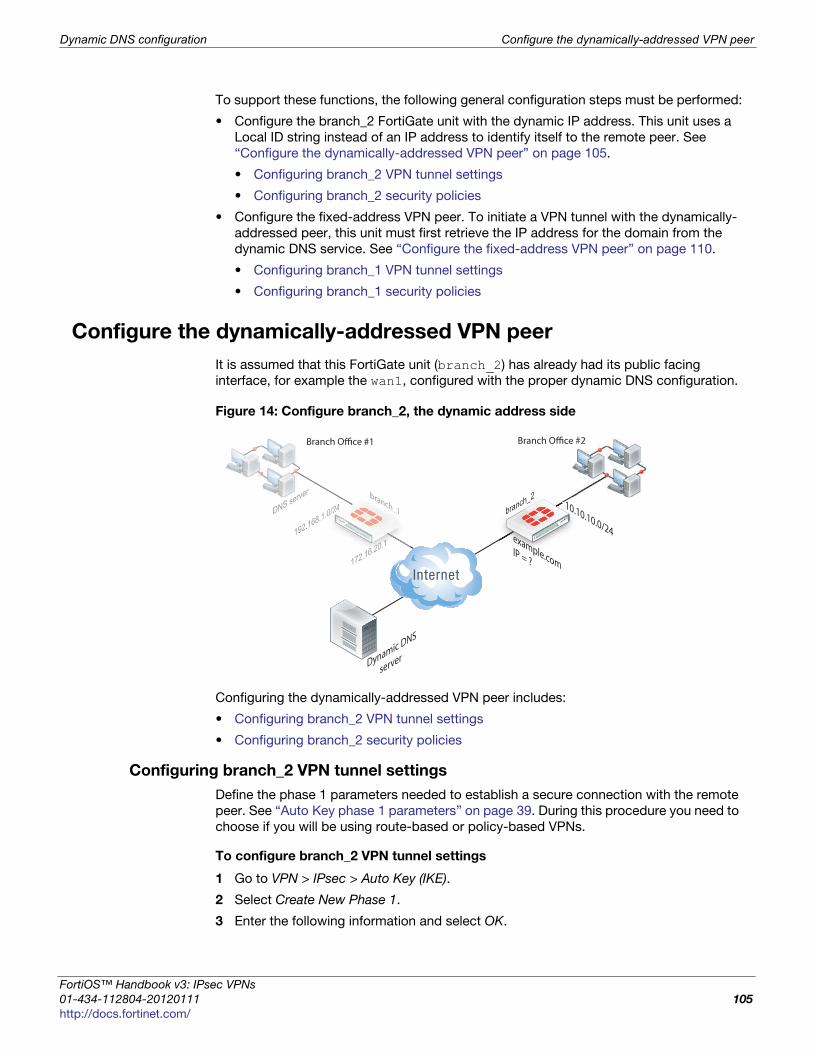
Dynamic DNS configuration Configure the dynamically-addressed VPN peer
F
0
h
To support these functions, the following general configuration steps must be performed:
• Configure the branch_2 FortiGate unit with the dynamic IP address. This unit uses a
Local ID string instead of an IP address to identify itself to the remote peer. See
“Configure the dynamically-addressed VPN peer” on page 105.
• Configuring branch_2 VPN tunnel settings
• Configuring branch_2 security policies
• Configure the fixed-address VPN peer. To initiate a VPN tunnel with the dynamically-
addressed peer, this unit must first retrieve the IP address for the domain from the
dynamic DNS service. See “Configure the fixed-address VPN peer” on page 110.
• Configuring branch_1 VPN tunnel settings
• Configuring branch_1 security policies
Configure the dynamically-addressed VPN peer
It is assumed that this FortiGate unit (branch_2) has already had its public facing
interface, for example the wan1, configured with the proper dynamic DNS configuration.
Figure 14: Configure branch_2, the dynamic address side
Configuring the dynamically-addressed VPN peer includes:
• Configuring branch_2 VPN tunnel settings
• Configuring branch_2 security policies
Configuring branch_2 VPN tunnel settings
Define the phase 1 parameters needed to establish a secure connection with the remote
peer. See “Auto Key phase 1 parameters” on page 39. During this procedure you need to
choose if you will be using route-based or policy-based VPNs.
To configure branch_2 VPN tunnel settings
1 Go to VPN > IPsec > Auto Key (IKE).
2 Select Create New Phase 1.
3 Enter the following information and select OK.
branch_1 branch_2
Dynamic DNS
server
Branch Office #2
DNS server
example.comIP = ?172.16.20.1
10.10.10.0/24192.168.1.0/24branch
anch_1DNS server
172.16.20.20.1192.168.1.00/24 1
Branch Office #1
ortiOS™ Handbook v3: IPsec VPNs
1-434-112804-20120111 105ttp://docs.fortinet.com/
Configure the dynamically-addressed VPN peer Dynamic DNS configuration
4 Select Create Phase 2.
Define the phase 2 parameters needed to create a VPN tunnel with the remote peer.
For details on phase 2, see “Phase 2 parameters” on page 57.
5 Enter the following information and select OK.
Configuring branch_2 security policies
Define security policies to permit communications between the private networks through
the VPN tunnel. Route-based and policy-based VPNs require different security policies.
For detailed information about creating security policies, see “Defining VPN security
policies” on page 64.
After defining the two address ranges, select one of “Creating branch_2 route-based
security policies” on page 107 or “Creating branch_2 policy-based security policies” on
page 109 to configure the appropriate VPN policies.
Name
Enter branch_2, a name to identify the VPN tunnel. This name
appears in phase 2 configurations, security policies, and the VPN
monitor.
Remote Gateway
Select Static IP Address.
The remote peer this FortiGate is connecting to has a static IP
public address.
If the remote interface is PPPoE do not select Retrieve default
gateway from server.
IP AddressEnter 172.16.20.1
The IP address of the public interface to the remote peer.
Mode Select Aggressive.
Advanced
Enable IPsec
Interface Mode
Enable for a route-based VPN and when configuring policies, go
to “Creating branch_2 route-based security policies” on
page 107.
Disable for a policy-based VPN and when configuring policies,
go to “Creating branch_2 policy-based security policies” on
page 109.
If enabled, default settings are used.
Local ID
Enter example.com
A character string used by the branch_2 FortiGate unit to
identify itself to the remote peer.
This value must be identical to the value in the Accept this peer
ID field of the phase 1 remote gateway configuration on the
branch_1 remote peer. See “Configuring branch_1 VPN tunnel
settings” on page 110.
NameEnter branch_2_phase2.
A name to identify this phase 2 configuration.
Phase 1Select branch_2.
The name of the phase 1 configuration that you defined earlier.
IPsec VPNs for FortiOS 4.0 MR3
106 01-434-112804-20120111
http://docs.fortinet.com/

Dynamic DNS configuration Configure the dynamically-addressed VPN peer
F
0
h
Define address ranges for branch_2 security policiesDefine VPN connection names for the address ranges of the private networks. These
addresses are used in the security policies that permit communication between the
networks. For more information, see “Defining policy addresses” on page 63.
Define an address name for the IP address and netmask of the private network behind
the local FortiGate unit.
To define branch_2 address ranges
1 Go to Firewall Objects > Address > Address.
2 Select Create New.
3 Enter the following information, and select OK.
Define an address name for the IP address and netmask of the private network behind
the remote peer.
4 Select Create New.
5 Enter the following information, and select OK.
Creating branch_2 route-based security policiesDefine ACCEPT security policies to permit communication between the branch_2 and
branch_1 private networks.
Once the route-based policy is configured a routing entry must be configured to route
traffic over the VPN interface.
Address Name Enter branch_2_internal. Enter a meaningful name.
Type Subnet/IP Range.
Subnet / IP Range10.10.10.0/24
Include the netmask or specify a specific range.
Interface
internal
The interface that will be handling the traffic from the internal
network.
Address Name
Enter branch_1_internal.
A meaningful name for the private network at the remote end of the
VPN tunnel.
Type Subnet/IP Range.
Subnet / IP Range192.168.1.0/24
Include the netmask. Optionally you can specify a range.
Interface
any
The interface that will be handling the remote VPN traffic on this
FortiGate unit.
If you are unsure, or multiple interfaces may be handling this traffic
use any.
ortiOS™ Handbook v3: IPsec VPNs
1-434-112804-20120111 107ttp://docs.fortinet.com/
Configure the dynamically-addressed VPN peer Dynamic DNS configuration
To create route-based security policies
1 Go to Policy > Policy > Policy.
2 Select Create New.
Define a policy to permit the branch_2 local FortiGate unit to initiate a VPN session
with the branch_1 VPN peer.
3 Enter the following information, and select OK.
4 Optionally configure any other security policy settings you require such as UTM or
traffic shaping for this policy.
Define a policy to permit the branch_1 remote VPN peer to initiate VPN sessions.
5 Enter the following information, and select OK.
Source Interface/Zone
Select internal.
The interface that connects to the private network behind
this FortiGate unit.
Source Address Name
Select branch_2_internal.
Select the address name for the private network behind this
FortiGate unit.
Destination
Interface/Zone
Select branch_2.
The VPN Tunnel (IPsec Interface).
Destination Address
Name
Select branch_1_internal
The address name the private network behind the remote
peer.
ActionSelect ACCEPT.
Accept VPN traffic on this interface pair in this direction.
NAT Disable.
Comment route-based: Initiate a branch_2 to branch_1 VPN tunnel
Source Interface/ZoneSelect branch_2.
The VPN Tunnel (IPsec Interface).
Source Address Name
Select branch_1_internal.
The address name for the private network behind the
remote peer.
Destination
Interface/Zone
Select internal.
The interface connecting the private network behind this
FortiGate unit.
Destination Address
Name
Select branch_2_internal.
The address name for the private network behind this
FortiGate unit.
Action Select ACCEPT.
NAT Disable.
Commentroute-based: Initiate a branch_1 to branch_2 internal VPN
tunnel.
IPsec VPNs for FortiOS 4.0 MR3
108 01-434-112804-20120111
http://docs.fortinet.com/

Dynamic DNS configuration Configure the dynamically-addressed VPN peer
F
0
h
6 Optionally configure any other security policy settings you require such as UTM or
traffic shaping for this policy.
7 Place these policies in the policy list above any other policies having similar source
and destination addresses. This will ensure VPN traffic is matched against the VPN
policies before any other policies.
To create routing entry for VPN interface - CLI
config router staticedit 5set dst 0.0.0.0 0.0.0.0set dynamic-dateway enableset device wan1
nextend
Creating branch_2 policy-based security policiesDefine an IPsec policy to permit VPN sessions between the private networks.
1 Go to Policy > Policy > Policy.
2 Select Create New.
Define an IPsec policy to permit the VPN sessions between the local branch_2 unit
and the remote branch_1 unit.
3 Enter the following information, and select OK.
This routing entry must be added in the CLI because the dynamic-gateway option is not
available in the web-based manager.
Source Interface/Zone
Select internal.
The interface connecting the private network behind this
FortiGate unit.
Source Address Name
Select branch_2_internal.
The address name for the private network behind this local
FortiGate unit.
Destination
Interface/Zone
Select wan1.
The FortiGate unit’s public interface.
Destination Address
Name
Select branch_1_internal.
The address name for the private network behind branch_1,
the remote peer.
Action Select IPSEC.
VPN TunnelSelect branch_2
The name of the phase 1 tunnel.
Allow Inbound
Allow Outbound
Select both Allow inbound and Allow outbound to enable
traffic from either direction to initiate the tunnel.
If you have problems connecting, try enabling NAT.
Commentpolicy-based: allows traffic in either direction to initiate the
VPN tunnel.
ortiOS™ Handbook v3: IPsec VPNs
1-434-112804-20120111 109ttp://docs.fortinet.com/
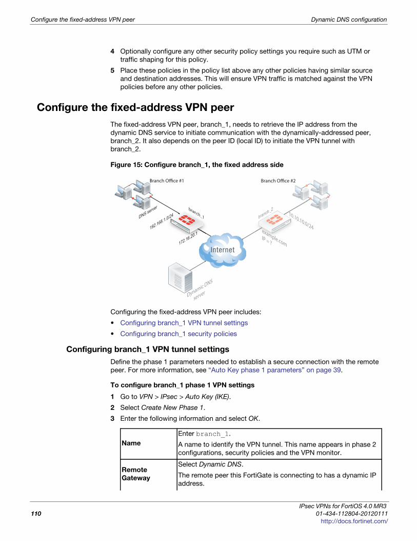
Configure the fixed-address VPN peer Dynamic DNS configuration
4 Optionally configure any other security policy settings you require such as UTM or
traffic shaping for this policy.
5 Place these policies in the policy list above any other policies having similar source
and destination addresses. This will ensure VPN traffic is matched against the VPN
policies before any other policies.
Configure the fixed-address VPN peer
The fixed-address VPN peer, branch_1, needs to retrieve the IP address from the
dynamic DNS service to initiate communication with the dynamically-addressed peer,
branch_2. It also depends on the peer ID (local ID) to initiate the VPN tunnel with
branch_2.
Figure 15: Configure branch_1, the fixed address side
Configuring the fixed-address VPN peer includes:
• Configuring branch_1 VPN tunnel settings
• Configuring branch_1 security policies
Configuring branch_1 VPN tunnel settings
Define the phase 1 parameters needed to establish a secure connection with the remote
peer. For more information, see “Auto Key phase 1 parameters” on page 39.
To configure branch_1 phase 1 VPN settings
1 Go to VPN > IPsec > Auto Key (IKE).
2 Select Create New Phase 1.
3 Enter the following information and select OK.
Branch Office #1
branch_1anch_1 branch_2
Dynamic DNS
server
Branch Office #2
DNS server
example.comIP = ?172.16.20.1
10.10.10.0/24192.168.1.0/24 nch_2branch_
ample.com
examIP = ?
10.10.10.0/24
10.
Dynamic DNS
server
Name
Enter branch_1.
A name to identify the VPN tunnel. This name appears in phase 2
configurations, security policies and the VPN monitor.
Remote
Gateway
Select Dynamic DNS.
The remote peer this FortiGate is connecting to has a dynamic IP
address.
IPsec VPNs for FortiOS 4.0 MR3
110 01-434-112804-20120111
http://docs.fortinet.com/

Dynamic DNS configuration Configure the fixed-address VPN peer
F
0
h
4 Define the phase 2 parameters needed to create a VPN tunnel with the remote peer.
See “Phase 2 parameters” on page 57. Enter these settings in particular:
Configuring branch_1 security policies
The branch_1 FortiGate unit has a fixed IP address and will be connecting to the
branch_2 FortiGate unit that has a dynamic IP address and a domain name of
example.com.
Remember if you are using route-based security policies that you must add a route for
the VPN traffic.
Defining address ranges for branch_1 security policiesAs with branch_2 previously, branch_1 needs address ranges defined as well. See
“Defining policy addresses” on page 63.
1 Go to Firewall Objects > Address > Address.
2 Select Create New.
3 Enter the following information, and select OK.
Dynamic DNSType the fully qualified domain name of the remote peer (for
example, example.com).
Interface
Enter wan1.
The public facing interface on the fixed-address FortiGate unit.
This interface cannot be a loopback interface.
Mode Select Aggressive.
Peer Options
Select Accept this peer ID, and enter example.com. This option
only appears when the mode is set to Aggressive.
The identifier of the FortiGate unit with the dynamic address.
Advanced
Enable IPsec
Interface Mode
Enable for a route-based VPN and when configuring policies, go to
“Creating branch_1 route-based security policies” on page 112.
Disable for a policy-based VPN and when configuring policies, go
to “Creating branch_1 policy-based security policies” on
page 113.
If Interface mode is enabled, default settings are used.
NameEnter branch_1_p2.
A name to identify this phase 2 configuration.
Phase 1
Select branch_1.
The name of the phase 1 configuration that you defined for the
remote peer. You can select the name of the remote gateway from
the Dynamic DNS part of the list.
Address Name
Enter branch_2_internal.
A meaningful name for the private network behind the branch_2
FortiGate unit.
Type Subnet/IP Range.
ortiOS™ Handbook v3: IPsec VPNs
1-434-112804-20120111 111ttp://docs.fortinet.com/
Configure the fixed-address VPN peer Dynamic DNS configuration
4 Define an address name for the IP address and netmask of the private network behind
the remote peer.
5 Select Create New.
6 Enter the following information, and select OK.
Creating branch_1 route-based security policiesDefine an ACCEPT security policy to permit communications between the source and
destination addresses. See “Defining VPN security policies” on page 64.
1 Go to Policy > Policy > Policy.
2 Select Create New.
3 Enter the following information, and select OK.
Subnet / IP Range10.10.10.0/24
Include the netmask or specify a specific range.
Interface
internal
This is the interface on this FortiGate unit that will be handling with
this traffic.
Address Name
Enter branch_1_internal.
A meaningful name for the private network behind the branch_1
peer.
Type Subnet/IP Range.
Subnet / IP Range192.168.1.0/24
Include the netmask or specify a specific range.
Interface
any
The interface on this FortiGate unit that will be handling with this
traffic. If you are unsure, or multiple interfaces may be handling this
traffic use any.
Source Interface/Zone
Select internal.
The interface that connects to the private network
behind the branch_1 FortiGate unit.
Source Address Name
Select branch_1_internal.
The address name that you defined for the private
network behind this FortiGate unit.
Destination Interface/Zone
Select branch_1.
The VPN Tunnel (IPsec Interface) you configured
earlier.
Destination Address Name
Select branch_2_internal.
The address name that you defined for the private
network behind the branch_2 peer.
Action Select ACCEPT.
NAT Disable
Comments Internal -> branch22
IPsec VPNs for FortiOS 4.0 MR3
112 01-434-112804-20120111
http://docs.fortinet.com/

Dynamic DNS configuration Configure the fixed-address VPN peer
F
0
h
To permit the remote client to initiate communication, you need to define a security
policy for communication in that direction.
4 Select Create New.
5 Enter the following information, and select OK.
Creating branch_1 policy-based security policiesA policy-based security policy allows you the flexibility to allow inbound or outbound
traffic or both through this single policy.
This policy-based IPsec VPN security policy allows both inbound and outbound traffic
1 Go to Policy > Policy > Policy.
2 Select Create New.
3 Enter the following information, and select OK.
Source Interface/Zone
Select branch_1
The VPN Tunnel (IPsec Interface) you configured
earlier.
Source Address Name
Select branch_2_internal.
The address name that you defined for the private
network behind the branch_2 remote peer.
Destination Interface/Zone
Select internal.
The interface that connects to the private network
behind this FortiGate unit.
Destination Address Name
Select branch_1_internal.
The address name that you defined for the private
network behind this FortiGate unit.
Action Select ACCEPT.
NAT Disable
Comments branch_2 -> Internal
Source Interface/Zone
Select internal.
The interface that connects to the private network
behind this FortiGate unit.
Source Address Name
Select branch_1_internal.
The address name that you defined for the private
network behind this FortiGate unit.
Destination Interface/ZoneSelect wan1.
The FortiGate unit’s public interface.
Destination Address Name
Select branch_2_internal.
The address name that you defined for the private
network behind the remote peer.
ortiOS™ Handbook v3: IPsec VPNs
1-434-112804-20120111 113ttp://docs.fortinet.com/
Testing Dynamic DNS configuration
4 Place this security policy in the policy list above any other policies having similar
source and destination addresses.
Testing
Once both ends are configured, you can test the VPN tunnel.
To test the VPN initiated by branch_2
1 On branch_2, go to VPN > Monitor > IPsec Monitor.
All IPsec VPN tunnels will be listed on this page, no matter if they are connected or
disconnected.
2 Select the tunnel listed for branch_2, and select the status column for that entry.
The status will say Bring Up and remote port, incoming and outgoing data will all be
zero. This indicates an inactive tunnel. When you select Bring Up, the FortiGate will try
to set up a VPN session over this tunnel. If it is successful, Bring Up will change to
Active, and the arrow icon will change to a green up arrow icon.
3 If this does not create a VPN tunnel with increasing values for incoming and outgoing
data, you need to start troubleshooting:
To test the VPN initiated by branch_1
1 On branch_1, go to VPN > Monitor > IPsec Monitor.
2 Select the tunnel listed for branch_1, and select the status column.
The difference between branch_2 and branch_1 at this point is that the tunnel entry for
branch-1 will not have a remote gateway IP address. It will be resolved when the VPN
tunnel is started.
3 If this does not create a VPN tunnel with increasing values for incoming and outgoing
data, you need to start troubleshooting.
Some troubleshooting ideas include:
• If there was no entry for the tunnel on the monitor page, check the Auto Key (IKE)
page to verify the phase 1 and phase 2 entries exist.
• Check the security policy or policies, and ensure there is an outgoing policy as a
minimum.
• Check that you entered a local ID in the phase 1 configuration, and that branch_1 has
the same local ID.
• Ensure the local DNS server has an up-to-date DNS entry for exmaple.com.
For more information on VPN troubleshooting and testing, see “VPN troubleshooting
tips” on page 241.
Action Select IPSEC.
VPN Tunnel
Select branch_1.
The name of the phase 1 configuration that you
created earlier.
Select Allow inbound to enable traffic from the remote
network to initiate the tunnel.
Select Allow outbound to enable traffic from the local
network to initiate the tunnel.
IPsec VPNs for FortiOS 4.0 MR3
114 01-434-112804-20120111
http://docs.fortinet.com/

F o r t i O S H a n d b o o k
F
0
h
FortiClient dialup-client configurations
The FortiClient Endpoint Security application is an IPsec VPN client with antivirus,
antispam and firewall capabilities. This section explains how to configure dialup VPN
connections between a FortiGate unit and one or more FortiClient Endpoint Security
applications.
FortiClient users are usually mobile or remote users who need to connect to a private
network behind a FortiGate unit. For example, the users might be employees who
connect to the office network while traveling or from their homes.
For greatest ease of use, the FortiClient application can download the VPN settings from
the FortiGate unit to configure itself automatically. This section covers both automatic
and manual configuration.
The following topics are included in this section:
• Configuration overview
• FortiClient-to-FortiGate VPN configuration steps
• Configure the FortiGate unit
• Configure the FortiClient Endpoint Security application
• Adding XAuth authentication
• FortiClient dialup-client configuration example
Configuration overview
Dialup users typically obtain dynamic IP addresses from an ISP through Dynamic Host
Configuration Protocol (DHCP) or Point-to-Point Protocol over Ethernet (PPPoE). Then,
the FortiClient Endpoint Security application initiates a connection to a FortiGate dialup
server.
By default the FortiClient dialup client has the same IP address as the host PC on which
it runs. If the host connects directly to the Internet, this is a public IP address. If the host
is behind a NAT device, such as a router, the IP address is a private IP address. The NAT
device must be NAT traversal (NAT-T) compatible to pass encrypted packets (see “NAT
traversal” on page 52). The FortiClient application also can be configured to use a virtual
IP address (VIP). For the duration of the connection, the FortiClient application and the
FortiGate unit both use the VIP address as the IP address of the FortiClient dialup client.
For a faster and easier method of configuring a FortiGate - to - FortiClient VPN, see “One
button FortiGate - to - FortiClient Phase1 VPN” on page 117.
The FortiClient configurations in this guide do not apply to the FortiClient Consumer
Edition, which does not include the IPsec VPN feature.
ortiOS™ Handbook v3: IPsec VPNs
1-434-112804-20120111 115ttp://docs.fortinet.com/
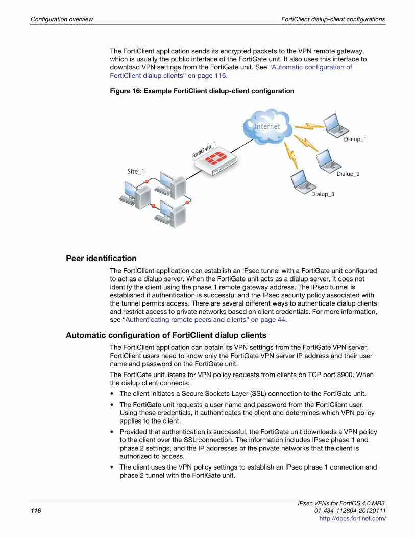
Configuration overview FortiClient dialup-client configurations
The FortiClient application sends its encrypted packets to the VPN remote gateway,
which is usually the public interface of the FortiGate unit. It also uses this interface to
download VPN settings from the FortiGate unit. See “Automatic configuration of
FortiClient dialup clients” on page 116.
Figure 16: Example FortiClient dialup-client configuration
Peer identification
The FortiClient application can establish an IPsec tunnel with a FortiGate unit configured
to act as a dialup server. When the FortiGate unit acts as a dialup server, it does not
identify the client using the phase 1 remote gateway address. The IPsec tunnel is
established if authentication is successful and the IPsec security policy associated with
the tunnel permits access. There are several different ways to authenticate dialup clients
and restrict access to private networks based on client credentials. For more information,
see “Authenticating remote peers and clients” on page 44.
Automatic configuration of FortiClient dialup clients
The FortiClient application can obtain its VPN settings from the FortiGate VPN server.
FortiClient users need to know only the FortiGate VPN server IP address and their user
name and password on the FortiGate unit.
The FortiGate unit listens for VPN policy requests from clients on TCP port 8900. When
the dialup client connects:
• The client initiates a Secure Sockets Layer (SSL) connection to the FortiGate unit.
• The FortiGate unit requests a user name and password from the FortiClient user.
Using these credentials, it authenticates the client and determines which VPN policy
applies to the client.
• Provided that authentication is successful, the FortiGate unit downloads a VPN policy
to the client over the SSL connection. The information includes IPsec phase 1 and
phase 2 settings, and the IP addresses of the private networks that the client is
authorized to access.
• The client uses the VPN policy settings to establish an IPsec phase 1 connection and
phase 2 tunnel with the FortiGate unit.
FortiGate_1
Site_1
FortiGate_
Dialup_1
Dialup_2
Dialup_3
IPsec VPNs for FortiOS 4.0 MR3
116 01-434-112804-20120111
http://docs.fortinet.com/

FortiClient dialup-client configurations Configuration overview
F
0
h
One button FortiGate - to - FortiClient Phase1 VPN
On the FortiOS VPN IKE page there is a button to create a Phase1 portion of a VPN
tunnel between the FortiGate and FortiClient. Very little information is required for this
configuration. No encryption or authentication method is required. This feature is ideal for
setting up quick VPN connections with basic settings.
On the Phase 1 screen (VPN > IPsec > Phase 1) is a button called Create a FortiClient
VPN. This button asks a few basic VPN configuration related questions. Once all the
information is added, click Create Now. This will create a new dial-up IPsec-interface
mode tunnel. Phase 1 and Phase 2 will be added using the default ike settings.
The following Settings will be used when creating a one-button FortiClient VPN Phase1
object:
• Remote Gateway: Dialup User
• Mode: Aggressive
• Enable IPSec Interface Mode
• Default setting for P1 and P2 Proposal
• XAUTH Enable as Server (Auto)
• IKE mode-config will be enabled
• Peer Option set to "Accept any peer ID"
• Rest of the setting use the current defaults (Default value needs to be the same on
FCT side)
Once the one button Phase1 is complete, you must create a default Phase2
configuration. This only requires a name for the Phase2 object, and select the one-button
Phase1 name.
How the FortiGate unit determines which settings to applyThe FortiGate unit follows these steps to determine the configuration information to send
to the FortiClient application:
1 Check the virtual domain associated with the connection to determine which VPN
policies might apply.
2 Select the VPN policy that matches the dialup client’s user group and determine
which tunnel (phase 1 configuration) is involved.
3 Check all IPsec security policies that use the specified tunnel to determine which
private networks the dialup clients may access.
4 Retrieve the rest of the VPN policy information from the existing IPsec phase 1 and
phase 2 parameters in the dialup-client configuration.
This one button is only compatible with FortiClient 4.3 and higher. Earlier versions of
FortiClient need to create IKE Phase-1 object separately, similar to earlier versions of
FortiOS.
ortiOS™ Handbook v3: IPsec VPNs
1-434-112804-20120111 117ttp://docs.fortinet.com/
Configuration overview FortiClient dialup-client configurations
Using virtual IP addresses
When the FortiClient host PC is located behind a NAT device, unintended IP address
overlap issues may arise between the private networks at the two ends of the tunnel. For
example, the client’s host might receive a private IP address from a DHCP server on its
network that by co-incidence is the same as a private IP address on the network behind
the FortiGate unit. A conflict will occur in the host’s routing table and the FortiClient
Endpoint Security application will be unable to send traffic through the tunnel.
Configuring virtual IP (VIP) addresses for FortiClient applications prevents this problem.
Using VIPs ensures that client IP addresses are in a predictable range. You can then
define security policies that allow access only to that source address range. If you do not
use VIPs, the security policies must allow all source addresses because you cannot
predict the IP address for a remote mobile user.
The FortiClient application must not have the same IP address as any host on the private
network behind the FortiGate unit or any other connected FortiClient application. You can
ensure this by reserving a range of IP addresses on the private network for FortiClient
users. Or, you can assign FortiClient VIPs from an uncommonly used subnet such as
10.254.254.0/24 or 192.168.254.0/24.
You can reserve a VIP address for a particular client according to its device MAC address
and type of connection. The DHCP server then always assigns the reserved VIP address
to the client. For more information about this feature, see the “dhcp reserved-address”
section in the “system” chapter of the FortiGate CLI Reference.
It is best to assign VIPs using DHCP over IPsec. The FortiGate dialup server can act as a
DHCP server or relay requests to an external DHCP server. You can also configure VIPs
manually on FortiClient applications, but it is more difficult to ensure that all clients use
unique addresses.
Figure 17 shows an example of a FortiClient-to-FortiGate VPN where the FortiClient
application is assigned a VIP on an uncommonly used subnet. The diagram also shows
that while the destination for the information in the encrypted packets is the private
network behind the FortiGate unit, the destination of the IPsec packets themselves is the
public interface of the FortiGate unit that acts as the end of the VPN tunnel.
On the host computer, you can find out the VIP address that the FortiClient Endpoint
Security application is using. For example,
On Windows, type ipconfig /all at the Windows Command Prompt.
On Linux or Mac OS X, type ifconfig in a terminal window.
The output will also show the IP address that has been assigned to the host Network
Interface Card (NIC).
If you assign a VIP on the private network behind the FortiGate unit and enable DHCP-
IPsec (a phase 2 advanced option), the FortiGate unit acts as a proxy on the local private
network for the FortiClient dialup client. Whenever a host on the network behind the
dialup server issues an ARP request for the device MAC address of the FortiClient host,
the FortiGate unit answers the ARP request on behalf of the FortiClient host and forwards
the associated traffic to the FortiClient host through the tunnel. For more information, see
“DHCP-IPsec” on page 59.
FortiGate units fully support RFC 3456. The FortiGate DHCP over IPsec feature can be
enabled to allocate VIP addresses to FortiClient dialup clients using a FortiGate DHCP
server.
IPsec VPNs for FortiOS 4.0 MR3
118 01-434-112804-20120111
http://docs.fortinet.com/
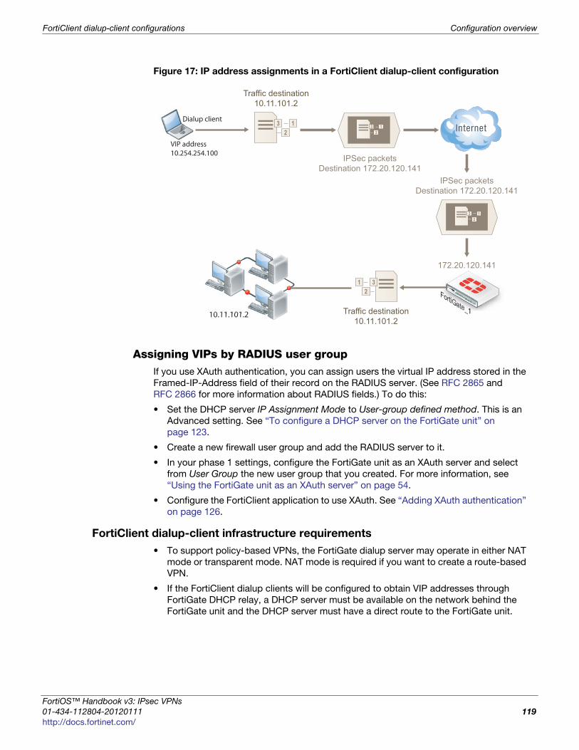
FortiClient dialup-client configurations Configuration overview
F
0
h
Figure 17: IP address assignments in a FortiClient dialup-client configuration
Assigning VIPs by RADIUS user groupIf you use XAuth authentication, you can assign users the virtual IP address stored in the
Framed-IP-Address field of their record on the RADIUS server. (See RFC 2865 and
RFC 2866 for more information about RADIUS fields.) To do this:
• Set the DHCP server IP Assignment Mode to User-group defined method. This is an
Advanced setting. See “To configure a DHCP server on the FortiGate unit” on
page 123.
• Create a new firewall user group and add the RADIUS server to it.
• In your phase 1 settings, configure the FortiGate unit as an XAuth server and select
from User Group the new user group that you created. For more information, see
“Using the FortiGate unit as an XAuth server” on page 54.
• Configure the FortiClient application to use XAuth. See “Adding XAuth authentication”
on page 126.
FortiClient dialup-client infrastructure requirements
• To support policy-based VPNs, the FortiGate dialup server may operate in either NAT
mode or transparent mode. NAT mode is required if you want to create a route-based
VPN.
• If the FortiClient dialup clients will be configured to obtain VIP addresses through
FortiGate DHCP relay, a DHCP server must be available on the network behind the
FortiGate unit and the DHCP server must have a direct route to the FortiGate unit.
10.11.101.2
VIP address10.254.254.100
Dialup client 3 12
IPSec packetsDestination 172.20.120.141
3 12
Traffic destination10.11.101.2
IPSec packetsDestination 172.20.120.141
3 12
172.20.120.141
FortiGate_1
312
Traffic destination10.11.101.2
ortiOS™ Handbook v3: IPsec VPNs
1-434-112804-20120111 119ttp://docs.fortinet.com/
FortiClient-to-FortiGate VPN configuration steps FortiClient dialup-client configurations
• If the FortiGate interface to the private network is not the default gateway, the private
network behind the FortiGate unit must be configured to route IP traffic destined for
dialup clients back (through an appropriate gateway) to the FortiGate interface to the
private network. As an alternative, you can configure the IPsec security policy on the
FortiGate unit to perform inbound NAT on IP packets. Inbound NAT translates the
source addresses of inbound decrypted packets into the IP address of the FortiGate
interface to the local private network.
FortiClient-to-FortiGate VPN configuration steps
Configuring dialup client capability for FortiClient dialup clients involves the following
general configuration steps:
1 If you will be using VIP addresses to identify dialup clients, determine which VIP
addresses to use. As a precaution, consider using VIP addresses that are not
commonly used.
2 Configure the FortiGate unit to act as a dialup server. See “Configure the FortiGate
unit” on page 120.
3 If the dialup clients will be configured to obtain VIP addresses through DHCP over
IPsec, configure the FortiGate unit to act as a DHCP server or to relay DHCP requests
to an external DHCP server.
4 Configure the dialup clients. See “Configure the FortiClient Endpoint Security
application” on page 125.
Configure the FortiGate unit
Configuring the FortiGate unit to establish VPN connections with FortiClient Endpoint
Security users involves the following steps:
1 configure the VPN settings
2 if the dialup clients use automatic configuration, configure the FortiGate unit as a VPN
policy server
3 if the dialup clients obtain VIP addresses by DHCP over IPsec, configure an IPsec
DHCP server or relay
The procedures in this section cover basic setup of policy-based and route-based VPNs
compatible with FortiClient Endpoint Security. A route-based VPN is simpler to configure.
Configuring FortiGate unit VPN settings
To configure FortiGate unit VPN settings to support FortiClient users, you need to:
• configure the FortiGate Phase 1 VPN settings
• configure the FortiGate Phase 2 VPN settings
• add the security policy
1 At the local FortiGate unit, define the phase 1 configuration needed to establish a
secure connection with the FortiClient peer. See “Auto Key phase 1 parameters” on
page 39. Enter these settings in particular:
When a FortiGate unit has been configured to accept connections from FortiClient dialup-
clients, you can optionally arrange to have an IPsec VPN configuration downloaded to
FortiClient dialup clients automatically. For more information, see “Configuring the
FortiGate unit as a VPN policy server” on page 123.
IPsec VPNs for FortiOS 4.0 MR3
120 01-434-112804-20120111
http://docs.fortinet.com/
FortiClient dialup-client configurations Configure the FortiGate unit
F
0
h
2 Define the phase 2 parameters needed to create a VPN tunnel with the FortiClient
peer. See “Phase 2 parameters” on page 57. Enter these settings in particular:
3 Define names for the addresses or address ranges of the private networks that the
VPN links. These addresses are used in the security policies that permit
communication between the networks. For more information, see “Defining policy
addresses” on page 63.
Enter these settings in particular:
• Define an address name for the individual address or the subnet address that the
dialup users access through the VPN.
• If FortiClient users are assigned VIP addresses, define an address name for the
subnet to which these VIPs belong.
4 Define security policies to permit communication between the private networks
through the VPN tunnel. Route-based and policy-based VPNs require different
security policies. For detailed information about creating security policies, see
“Defining VPN security policies” on page 64.
Name
Enter a name to identify the VPN tunnel. This name
appears in phase 2 configurations, security policies and
the VPN monitor.
Remote Gateway Select Dialup User.
Local InterfaceSelect the interface through which clients connect to the
FortiGate unit.
Mode Select Main (ID Protection).
Authentication Method Select Pre-shared Key.
Pre-shared KeyEnter the pre-shared key. This must be the same
preshared key provided to the FortiClient users.
Peer option Select Accept any peer ID.
Enable IPsec Interface
Mode
You must select Advanced to see this setting. If IPsec
Interface Mode is enabled, the FortiGate unit creates a
virtual IPsec interface for a route-based VPN.
Name Enter a name to identify this phase 2 configuration.
Phase 1Select the name of the phase 1 configuration that you
defined.
Advanced Select to configure the following optional setting.
DHCP-IPsecSelect if you provide virtual IP addresses to clients using
DHCP.
If the security policy, which grants the VPN Connection is limited to certain services,
DHCP must be included, otherwise the client won’t be able to retrieve a lease from the
FortiGate’s (IPSec) DHCP server, because the DHCP Request (coming out of the tunnel)
will be blocked.
ortiOS™ Handbook v3: IPsec VPNs
1-434-112804-20120111 121ttp://docs.fortinet.com/
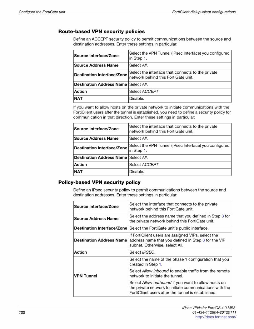
Configure the FortiGate unit FortiClient dialup-client configurations
Route-based VPN security policiesDefine an ACCEPT security policy to permit communications between the source and
destination addresses. Enter these settings in particular:
If you want to allow hosts on the private network to initiate communications with the
FortiClient users after the tunnel is established, you need to define a security policy for
communication in that direction. Enter these settings in particular:
Policy-based VPN security policyDefine an IPsec security policy to permit communications between the source and
destination addresses. Enter these settings in particular:
Source Interface/ZoneSelect the VPN Tunnel (IPsec Interface) you configured
in Step 1.
Source Address Name Select All.
Destination Interface/ZoneSelect the interface that connects to the private
network behind this FortiGate unit.
Destination Address Name Select All.
Action Select ACCEPT.
NAT Disable.
Source Interface/ZoneSelect the interface that connects to the private
network behind this FortiGate unit.
Source Address Name Select All.
Destination Interface/ZoneSelect the VPN Tunnel (IPsec Interface) you configured
in Step 1.
Destination Address Name Select All.
Action Select ACCEPT.
NAT Disable.
Source Interface/ZoneSelect the interface that connects to the private
network behind this FortiGate unit.
Source Address NameSelect the address name that you defined in Step 3 for
the private network behind this FortiGate unit.
Destination Interface/Zone Select the FortiGate unit’s public interface.
Destination Address Name
If FortiClient users are assigned VIPs, select the
address name that you defined in Step 3 for the VIP
subnet. Otherwise, select All.
Action Select IPSEC.
VPN Tunnel
Select the name of the phase 1 configuration that you
created in Step 1.
Select Allow inbound to enable traffic from the remote
network to initiate the tunnel.
Select Allow outbound if you want to allow hosts on
the private network to initiate communications with the
FortiClient users after the tunnel is established.
IPsec VPNs for FortiOS 4.0 MR3
122 01-434-112804-20120111
http://docs.fortinet.com/

FortiClient dialup-client configurations Configure the FortiGate unit
F
0
h
Place VPN policies in the policy list above any other policies having similar source and
destination addresses.
Configuring the FortiGate unit as a VPN policy server
When a FortiClient application set to automatic configuration connects to the FortiGate
unit, the FortiGate unit requests a user name and password. If the user supplies valid
credentials, the FortiGate unit downloads the VPN settings to the FortiClient application.
You must do the following to configure the FortiGate unit to work as a VPN policy server
for FortiClient automatic configuration:
1 Create user accounts for FortiClient users.
2 Create a user group for FortiClient users and the user accounts that you created in
step 1.
3 Connect to the FortiGate unit CLI and configure VPN policy distribution as follows:
config vpn ipsec forticlientedit <policy_name>set phase2name <tunnel_name>set usergroupname <group_name>set status enable
end
<tunnel_name> must be the Name you specified in the step 2 of “Configure the
FortiGate unit” on page 120. <group_name> must be the name of the user group
your created for FortiClient users.
Configuring DHCP service on the FortiGate unit
If the FortiClient dialup clients are configured to obtain a VIP address using DHCP,
configure the FortiGate dialup server to either:
• relay DHCP requests to a DHCP server behind the FortiGate unit (see “To configure
DHCP relay on the FortiGate unit” below).
• act as a DHCP server (see “To configure a DHCP server on the FortiGate unit” on
page 123).
To configure DHCP relay on the FortiGate unit
1 Go to System > Network > DHCP Server and select Create New.
2 In Interface Name, select the interface that connects to the Internet (for example,
external or wan1).
3 In Mode, select Relay.
4 In Type select IPsec.
5 In the DHCP Server IP field, type the IP address of the DHCP server.
6 Select OK.
7 If a router is installed between the FortiGate unit and the DHCP server, define a static
route to the DHCP server.
To configure a DHCP server on the FortiGate unit
1 Go to System > DHCP Server and select Create New.
2 In Interface Name, select the interface that connects to the Internet (for example,
external or wan1).
3 In Mode, select Server.
ortiOS™ Handbook v3: IPsec VPNs
1-434-112804-20120111 123ttp://docs.fortinet.com/
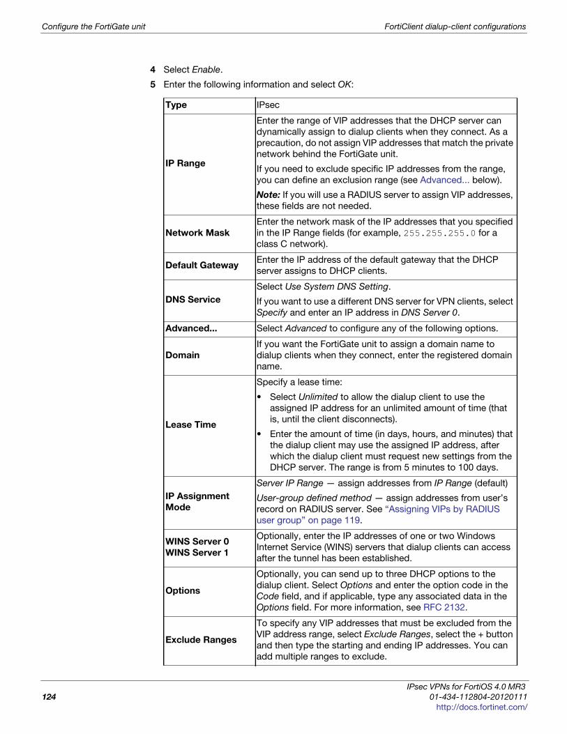
Configure the FortiGate unit FortiClient dialup-client configurations
4 Select Enable.
5 Enter the following information and select OK:
Type IPsec
IP Range
Enter the range of VIP addresses that the DHCP server can
dynamically assign to dialup clients when they connect. As a
precaution, do not assign VIP addresses that match the private
network behind the FortiGate unit.
If you need to exclude specific IP addresses from the range,
you can define an exclusion range (see Advanced... below).
Note: If you will use a RADIUS server to assign VIP addresses,
these fields are not needed.
Network Mask
Enter the network mask of the IP addresses that you specified
in the IP Range fields (for example, 255.255.255.0 for a
class C network).
Default GatewayEnter the IP address of the default gateway that the DHCP
server assigns to DHCP clients.
DNS Service
Select Use System DNS Setting.
If you want to use a different DNS server for VPN clients, select
Specify and enter an IP address in DNS Server 0.
Advanced... Select Advanced to configure any of the following options.
Domain
If you want the FortiGate unit to assign a domain name to
dialup clients when they connect, enter the registered domain
name.
Lease Time
Specify a lease time:
• Select Unlimited to allow the dialup client to use the
assigned IP address for an unlimited amount of time (that
is, until the client disconnects).
• Enter the amount of time (in days, hours, and minutes) that
the dialup client may use the assigned IP address, after
which the dialup client must request new settings from the
DHCP server. The range is from 5 minutes to 100 days.
IP Assignment
Mode
Server IP Range — assign addresses from IP Range (default)
User-group defined method — assign addresses from user’s
record on RADIUS server. See “Assigning VIPs by RADIUS
user group” on page 119.
WINS Server 0
WINS Server 1
Optionally, enter the IP addresses of one or two Windows
Internet Service (WINS) servers that dialup clients can access
after the tunnel has been established.
Options
Optionally, you can send up to three DHCP options to the
dialup client. Select Options and enter the option code in the
Code field, and if applicable, type any associated data in the
Options field. For more information, see RFC 2132.
Exclude Ranges
To specify any VIP addresses that must be excluded from the
VIP address range, select Exclude Ranges, select the + button
and then type the starting and ending IP addresses. You can
add multiple ranges to exclude.
IPsec VPNs for FortiOS 4.0 MR3
124 01-434-112804-20120111
http://docs.fortinet.com/
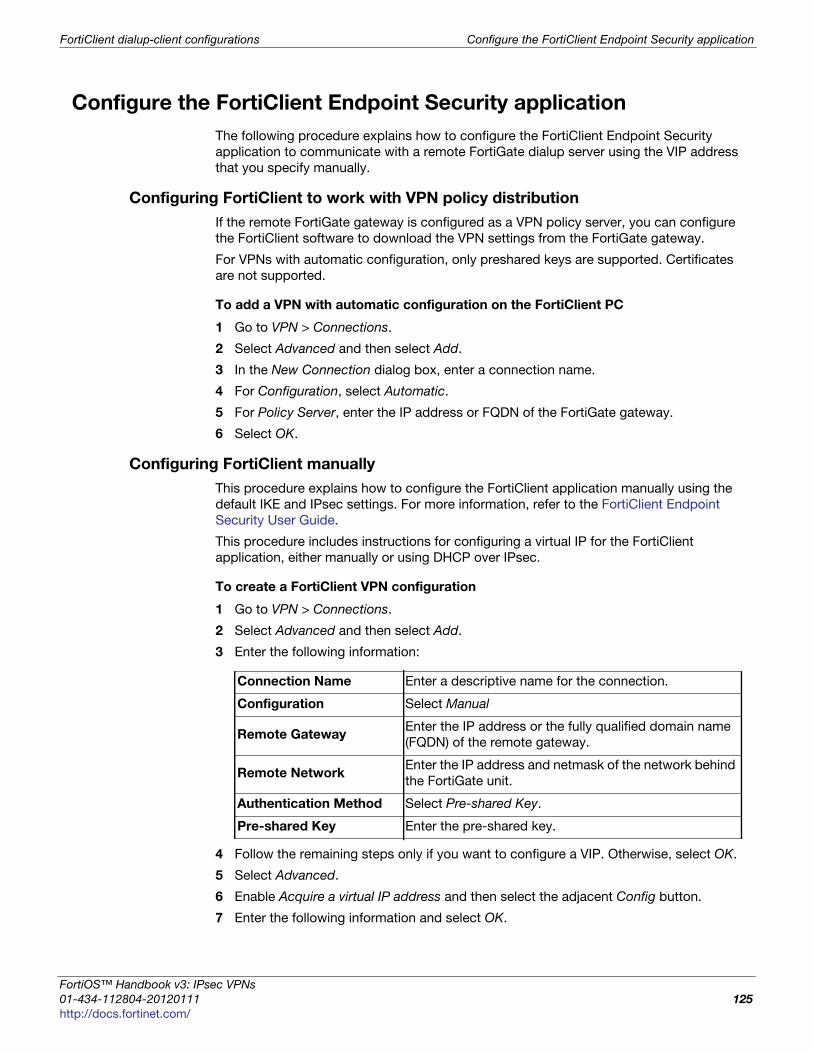
FortiClient dialup-client configurations Configure the FortiClient Endpoint Security application
F
0
h
Configure the FortiClient Endpoint Security application
The following procedure explains how to configure the FortiClient Endpoint Security
application to communicate with a remote FortiGate dialup server using the VIP address
that you specify manually.
Configuring FortiClient to work with VPN policy distribution
If the remote FortiGate gateway is configured as a VPN policy server, you can configure
the FortiClient software to download the VPN settings from the FortiGate gateway.
For VPNs with automatic configuration, only preshared keys are supported. Certificates
are not supported.
To add a VPN with automatic configuration on the FortiClient PC
1 Go to VPN > Connections.
2 Select Advanced and then select Add.
3 In the New Connection dialog box, enter a connection name.
4 For Configuration, select Automatic.
5 For Policy Server, enter the IP address or FQDN of the FortiGate gateway.
6 Select OK.
Configuring FortiClient manually
This procedure explains how to configure the FortiClient application manually using the
default IKE and IPsec settings. For more information, refer to the FortiClient Endpoint
Security User Guide.
This procedure includes instructions for configuring a virtual IP for the FortiClient
application, either manually or using DHCP over IPsec.
To create a FortiClient VPN configuration
1 Go to VPN > Connections.
2 Select Advanced and then select Add.
3 Enter the following information:
4 Follow the remaining steps only if you want to configure a VIP. Otherwise, select OK.
5 Select Advanced.
6 Enable Acquire a virtual IP address and then select the adjacent Config button.
7 Enter the following information and select OK.
Connection Name Enter a descriptive name for the connection.
Configuration Select Manual
Remote GatewayEnter the IP address or the fully qualified domain name
(FQDN) of the remote gateway.
Remote NetworkEnter the IP address and netmask of the network behind
the FortiGate unit.
Authentication Method Select Pre-shared Key.
Pre-shared Key Enter the pre-shared key.
ortiOS™ Handbook v3: IPsec VPNs
1-434-112804-20120111 125ttp://docs.fortinet.com/

Adding XAuth authentication FortiClient dialup-client configurations
8 Select OK twice to close the dialog boxes.
9 Repeat this procedure for each FortiClient dialup client.
Adding XAuth authentication
Extended Authentication (XAuth) increases security by requiring additional user
authentication in a separate exchange at the end of the VPN phase 1 negotiation. The
FortiGate unit challenges the user for a user name and password. It then forwards the
user’s credentials to an external RADIUS or LDAP server for verification.
Implementation of XAuth requires configuration at both the FortiGate unit and the
FortiClient application. For information about configuring a FortiGate unit as an XAuth
server, see “Using the FortiGate unit as an XAuth server” on page 54. The following
procedure explains how to configure the FortiClient application.
To configure the FortiClient Endpoint Security application
In the FortiClient Endpoint Security application, make the following changes to the VPN
configuration to enable XAuth authentication to the FortiGate unit.
1 Go to VPN > Connections, select the VPN connection you want to modify.
2 Select Advanced > Edit > Advanced.
3 Select the eXtended Authentication check box and then select the Config button to
the right of it.
Options Select one of these options:
DHCPObtain virtual IP address from the FortiGate unit using DHCP over
IPsec.
Manually SetAssign the virtual IP address manually using the settings in the
Manual VIP section.
Manual VIPThese settings are available only if you select Manually Set in the
Options section.
IP
Enter the IP address that the FortiClient dialup client uses. This
address must not conflict with any IP address at either end of the
VPN tunnel.
Subnet Mask Enter the subnet for the private network.
DNS Server
WINS Server
Optionally, enter the addresses of the DNS and WINS servers that
the FortiClient user can access through the VPN.
XAuth is not compatible with IKE version 2.
IPsec VPNs for FortiOS 4.0 MR3
126 01-434-112804-20120111
http://docs.fortinet.com/

FortiClient dialup-client configurations FortiClient dialup-client configuration example
F
0
h
4 In the Extended Authentication (XAuth) dialog box, select one of the 2 following
choices:
• To always prompt for username and password, select Prompt to login.
This is the default.
• To never prompt for username and password, clear the Prompt to login check box
and fill in the User Name and Password fields.
The FortiClient Endpoint Security application will use these values and
automatically responds to the XAuth challenge.
5 Select OK to close all dialog boxes.
FortiClient dialup-client configuration example
This example demonstrates how to set up a FortiClient dialup-client IPsec VPN that uses
preshared keys for authentication purposes. In the example configuration, the DHCP over
IPsec feature is enabled in the FortiClient Endpoint Security application so that the
FortiClient Endpoint Security application can acquire a VIP address through the FortiGate
DHCP server. Both route-based and policy-based solutions are covered.
Figure 18: Example FortiClient dialup-client configuration
In the example configuration:
• VIP addresses that are not commonly used (in this case, 10.254.254.0/24) are
assigned to the FortiClient dialup clients using a DHCP server.
• The dialup clients are have access to the LAN behind FortiGate_1.
• The other network devices are assigned IP addresses as shown in Figure 18.
Configuring FortiGate_1
When a FortiGate unit receives a connection request from a dialup client, it uses IPsec
phase 1 parameters to establish a secure connection and authenticate the client. Then, if
the security policy permits the connection, the FortiGate unit establishes the tunnel using
IPsec phase 2 parameters and applies the IPsec security policy. Key management,
authentication, and security services are negotiated dynamically through the IKE
protocol.
FortiGate_1
LAN10.11.101.0/24
VIP address10.254.254.1
VIP address10.254.254.2
FortiGate_
Dialup_1
Dialup_2
Port 1 172.20.120.141Port 2
ortiOS™ Handbook v3: IPsec VPNs
1-434-112804-20120111 127ttp://docs.fortinet.com/

FortiClient dialup-client configuration example FortiClient dialup-client configurations
To support these functions, the following general configuration steps must be performed
at the FortiGate unit:
• Define the phase 1 parameters that the FortiGate unit needs to authenticate the dialup
clients and establish a secure connection. See “To define the phase 1 parameters” on
page 128.
• Define the phase 2 parameters that the FortiGate unit needs to create a VPN tunnel
and enable all dialup clients having VIP addresses on the 10.254.254.0/24 network to
connect using the same tunnel definition. See “To define the phase 2 parameters” on
page 128.
• Create security policy to control the permitted services and permitted direction of
traffic between the IP source address and the dialup clients. See “To define the
firewall addresses” on page 128.
• Configure the FortiGate unit to service DHCP requests from dialup clients. See “To
configure a DHCP server on the FortiGate unit” on page 130.
To define the phase 1 parameters
1 Go to VPN > IPsec > Auto Key (IKE).
2 Select Create Phase 1, enter the following information, and select OK:
To define the phase 2 parameters
1 Go to VPN > IPsec > Auto Key (IKE)and select Create Phase 2.
2 Select Advanced, enter the following information, and select OK:
To define the firewall addresses
1 Go to Firewall Objects > Address > Address.
2 Select Create New, enter the following information, and select OK:
Name todialups
Remote Gateway Dialup User
Local Interface Port 1
Mode Main
Authentication Method Preshared Key
Pre-shared Key hardtoguess
Peer Options Accept any peer ID
Advanced Select
Enable IPsec Interface
Mode
Enable for route-based VPN.
Disable for policy-based VPN.
Name td_2
Phase 1 todialups
Advanced DHCP-IPsec
Address Name internal_net
Subnet/IP Range 10.11.101.0/24
Interface Port 2
IPsec VPNs for FortiOS 4.0 MR3
128 01-434-112804-20120111
http://docs.fortinet.com/
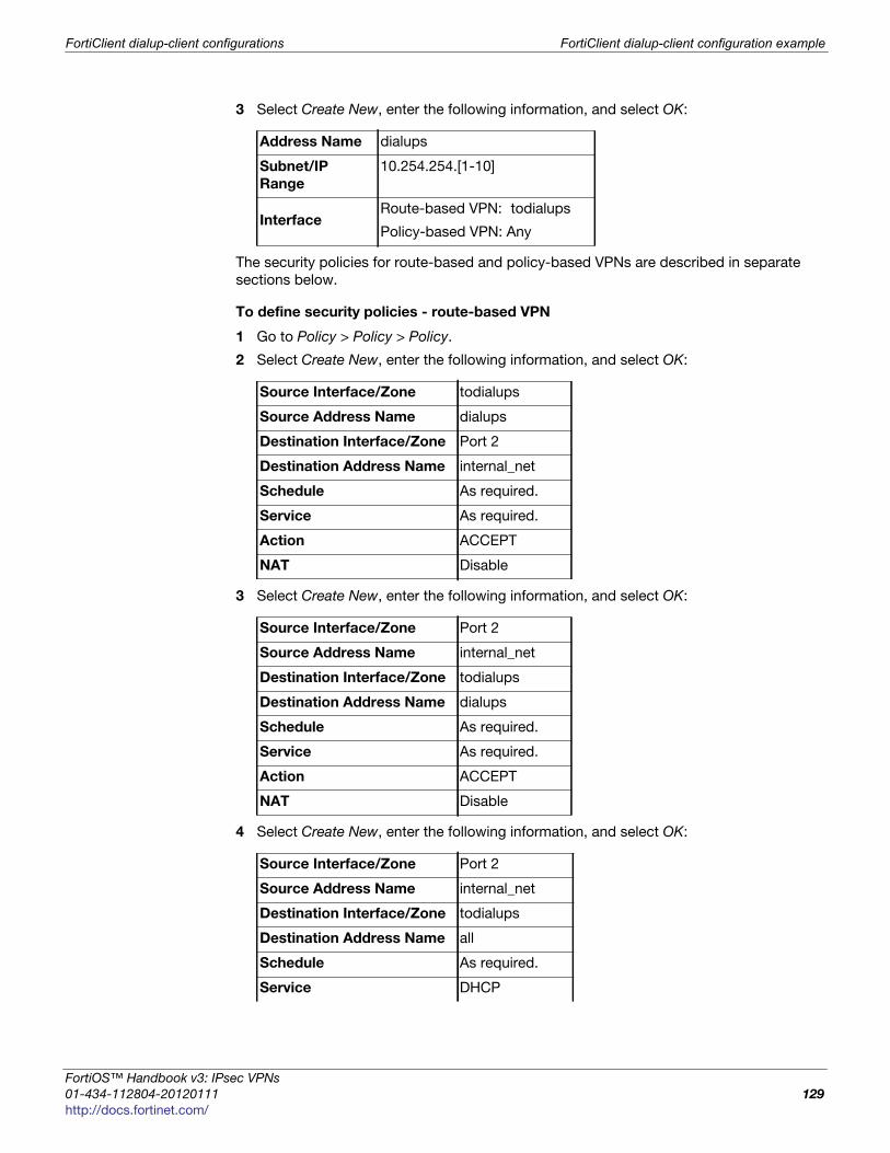
FortiClient dialup-client configurations FortiClient dialup-client configuration example
F
0
h
3 Select Create New, enter the following information, and select OK:
The security policies for route-based and policy-based VPNs are described in separate
sections below.
To define security policies - route-based VPN
1 Go to Policy > Policy > Policy.
2 Select Create New, enter the following information, and select OK:
3 Select Create New, enter the following information, and select OK:
4 Select Create New, enter the following information, and select OK:
Address Name dialups
Subnet/IP
Range
10.254.254.[1-10]
InterfaceRoute-based VPN: todialups
Policy-based VPN: Any
Source Interface/Zone todialups
Source Address Name dialups
Destination Interface/Zone Port 2
Destination Address Name internal_net
Schedule As required.
Service As required.
Action ACCEPT
NAT Disable
Source Interface/Zone Port 2
Source Address Name internal_net
Destination Interface/Zone todialups
Destination Address Name dialups
Schedule As required.
Service As required.
Action ACCEPT
NAT Disable
Source Interface/Zone Port 2
Source Address Name internal_net
Destination Interface/Zone todialups
Destination Address Name all
Schedule As required.
Service DHCP
ortiOS™ Handbook v3: IPsec VPNs
1-434-112804-20120111 129ttp://docs.fortinet.com/

FortiClient dialup-client configuration example FortiClient dialup-client configurations
5 Place these policies in the policy list above any other policies having similar source
and destination addresses.
To define the security policy - policy-based VPN
1 Go to Policy > Policy > Policy.
2 Select Create New, enter the following information, and select OK:
3 Place the policy in the policy list above any other policies having similar source and
destination addresses.
To configure a DHCP server on the FortiGate unit
1 Go to System > DHCP Server and select Create New.
2 Enter the following information and select OK:
Action ACCEPT
NAT Disable
The policy in step 4 is required for DHCP to function properly for policy-based VPNs. You
can omit this policy if you change the Destination Address Name to all in the step
before. Route-based policies are not affected by this.
Source Interface/Zone Port 2
Source Address Name internal_net
Destination Interface/Zone Port 1
Destination Address Name dialups
Schedule As required.
Service As required.
Action IPSEC
VPN Tunnel todialups.
Allow Inbound Enable
Allow Outbound
Enable if you want to allow hosts on the private
network behind the FortiGate unit to initiate
communications with the FortiClient users after the
tunnel is established.
Inbound NAT Disable
Outbound NAT Disable
Interface Name
Route-based VPN: select virtual IPsec interface. For example,
todialups.
Policy-based VPN: select the public interface. For example,
Port 1.
Mode Server
Type IPSEC.
IP Range 10.254.254.1 - 10.254.254.10
IPsec VPNs for FortiOS 4.0 MR3
130 01-434-112804-20120111
http://docs.fortinet.com/

FortiClient dialup-client configurations FortiClient dialup-client configuration example
F
0
h
Configuring the FortiClient Endpoint Security application
The following procedure explains how to configure the FortiClient Endpoint Security
application to connect to FortiGate_1 and broadcast a DHCP request. The dialup client
uses the VIP address acquired through FortiGate DHCP relay as its IP source address for
the duration of the connection.
To configure FortiClient
1 At the remote host, start FortiClient.
2 Go to VPN > Connections and select Advanced > Add.
3 Enter the following settings:
4 Select Advanced.
5 In the Advanced Settings dialog box, select Acquire virtual IP address and then select
Config.
6 Verify that the Dynamic Host Configuration Protocol (DHCP) over IPsec option is
selected, and then select OK.
7 Select OK twice to close the dialog boxes.
8 Exit FortiClient and repeat this procedure at all other remote hosts.
Network Mask 255.255.255.0
Default Gateway 172.20.120.2
Connection Name Office
VPN Type Manual IPsec
Remote Gateway 172.20.120.141
Remote Network 10.11.101.0 / 255.255.255.0
Authentication
Method
Preshared Key
Preshared Key hardtoguess
ortiOS™ Handbook v3: IPsec VPNs
1-434-112804-20120111 131ttp://docs.fortinet.com/

FortiClient dialup-client configuration example FortiClient dialup-client configurations
IPsec VPNs for FortiOS 4.0 MR3
132 01-434-112804-20120111
http://docs.fortinet.com/

F o r t i O S H a n d b o o k
F
0
h
FortiGate dialup-client configurations
This section explains how to set up a FortiGate dialup-client IPsec VPN. In a FortiGate
dialup-client configuration, a FortiGate unit with a static IP address acts as a dialup
server and a FortiGate unit having a dynamic IP address initiates a VPN tunnel with the
FortiGate dialup server.
The following topics are included in this section:
• Configuration overview
• FortiGate dialup-client configuration steps
• Configure the server to accept FortiGate dialup-client connections
• Configure the FortiGate dialup client
Configuration overview
A dialup client can be a FortiGate unit—the FortiGate dialup client typically obtains a
dynamic IP address from an ISP through the Dynamic Host Configuration Protocol
(DHCP) or Point-to-Point Protocol over Ethernet (PPPoE) before initiating a connection to
a FortiGate dialup server.
Figure 19: Example FortiGate dialup-client configuration
In a dialup-client configuration, the FortiGate dialup server does not rely on a phase 1
remote gateway address to establish an IPsec VPN connection with dialup clients. As
long as authentication is successful and the IPsec security policy associated with the
tunnel permits access, the tunnel is established.
FortiGate_1
Site_1 Site_2FortiG
ate_ FG_Dialup
ortiOS™ Handbook v3: IPsec VPNs
1-434-112804-20120111 133ttp://docs.fortinet.com/

Configuration overview FortiGate dialup-client configurations
Several different ways to authenticate dialup clients and restrict access to private
networks based on client credentials are available. To authenticate FortiGate dialup
clients and help to distinguish them from FortiClient dialup clients when multiple clients
will be connecting to the VPN through the same tunnel, best practices dictate that you
assign a unique identifier (local ID or peer ID) to each FortiGate dialup client. For more
information, see “Authenticating remote peers and clients” on page 44.
Users behind the FortiGate dialup server cannot initiate the tunnel because the FortiGate
dialup client does not have a static IP address. After the tunnel is initiated by users
behind the FortiGate dialup client, traffic from the private network behind the FortiGate
dialup server can be sent to the private network behind the FortiGate dialup client.
Encrypted packets from the FortiGate dialup client are addressed to the public interface
of the dialup server. Encrypted packets from the dialup server are addressed either to the
public IP address of the FortiGate dialup client (if the dialup client connects to the
Internet directly), or if the FortiGate dialup client is behind a NAT device, encrypted
packets from the dialup server are addressed to the public IP address of the NAT device.
When the FortiGate dialup server decrypts a packet from the FortiGate dialup client, the
source address in the IP header may be one of the following values, depending on the
configuration of the network at the far end of the tunnel:
• If the FortiGate dialup client connects to the Internet directly, the source address will
be the private IP address of a host or server on the network behind the FortiGate
dialup client.
• If the FortiGate dialup client is behind a NAT device, the source address will be the
public IP address of the NAT device.
In some cases, computers on the private network behind the FortiGate dialup client may
(by co-incidence) have IP addresses that are already used by computers on the network
behind the FortiGate dialup server. In this type of situation (ambiguous routing), conflicts
may occur in one or both of the FortiGate routing tables and traffic destined for the
remote network through the tunnel may not be sent.
In many cases, computers on the private network behind the FortiGate dialup client will
most likely obtain IP addresses from a local DHCP server behind the FortiGate dialup
client. However, unless the local and remote networks use different private network
address spaces, unintended ambiguous routing and IP-address overlap issues may
arise.
Whenever you add a unique identifier (local ID) to a FortiGate dialup client for
identification purposes, you must select Aggressive mode on the FortiGate dialup server
and also specify the identifier as a peer ID on the FortiGate dialup server. For more
information, see “Enabling VPN access with user accounts and pre-shared keys” on
page 47.
If a router with NAT capabilities is in front of the FortiGate dialup client, the router must be
NAT-T compatible for encrypted traffic to pass through the NAT device. For more
information, see “NAT traversal” on page 52.
IPsec VPNs for FortiOS 4.0 MR3
134 01-434-112804-20120111
http://docs.fortinet.com/

FortiGate dialup-client configurations Configuration overview
F
0
h
To avoid these issues, you can configure FortiGate DHCP relay on the dialup client
instead of using a DHCP server on the network behind the dialup client. The FortiGate
dialup client can be configured to relay DHCP requests from the local private network to
a DHCP server that resides on the network behind the FortiGate dialup server (see
Figure 20 on page 135). You configure the FortiGate dialup client to pass traffic from the
local private network to the remote network by enabling FortiGate DHCP relay on the
FortiGate dialup client interface that is connected to the local private network.
Afterward, when a computer on the network behind the dialup client broadcasts a DHCP
request, the dialup client relays the message through the tunnel to the remote DHCP
server. The remote DHCP server responds with a private IP address for the computer. To
avoid ambiguous routing and network overlap issues, the IP addresses assigned to
computers behind the dialup client cannot match the network address space used by the
private network behind the FortiGate dialup server.
Figure 20: Preventing network overlap in a FortiGate dialup-client configuration
When the DHCP server resides on the private network behind the FortiGate dialup server,
the IP destination address specified in the IPsec security policy on the FortiGate dialup
client must refer to that network.
FortiGate dialup-client infrastructure requirements
The requirements are:
• The FortiGate dialup server must have a static public IP address.
• NAT mode is required if you want to create a route-based VPN.
• The FortiGate dialup server may operate in either NAT mode or transparent mode to
support a policy-based VPN.
FortiGate_1
Site_1Site_2
FortiGate_
FG_Dialup
DHCP discoverymessage initiatestunnel
DHCP
server
You must add a static route to the DHCP server FortiGate unit if it is not directly
connected to the private network behind the FortiGate dialup server—its IP address does
not match the IP address of the private network. Also, the destination address in the
IPsec security policy on the FortiGate dialup client must refer to the DHCP server
address. The DHCP server must be configured to assign a range of IP addresses different
from the DHCP server's local network, and also different from the private network
addresses behind the FortiGate dialup server. See “Routing” on page 101.
ortiOS™ Handbook v3: IPsec VPNs
1-434-112804-20120111 135ttp://docs.fortinet.com/
FortiGate dialup-client configuration steps FortiGate dialup-client configurations
• Computers on the private network behind the FortiGate dialup client can obtain IP
addresses either from a DHCP server behind the FortiGate dialup client, or a DHCP
server behind the FortiGate dialup server.
• If the DHCP server resides on the network behind the dialup client, the DHCP
server must be configured to assign IP addresses that do not match the private
network behind the FortiGate dialup server.
• If the DHCP server resides on the network behind the FortiGate dialup server, the
DHCP server must be configured to assign IP addresses that do not match the
private network behind the FortiGate dialup client.
FortiGate dialup-client configuration steps
The procedures in this section assume that computers on the private network behind the
FortiGate dialup client obtain IP addresses from a local DHCP server. The assigned IP
addresses do not match the private network behind the FortiGate dialup server.
Configuring dialup client capability for FortiGate dialup clients involves the following
general configuration steps:
• Determine which IP addresses to assign to the private network behind the FortiGate
dialup client, and add the IP addresses to the DHCP server behind the FortiGate
dialup client. Refer to the software supplier’s documentation to configure the DHCP
server.
• Configure the FortiGate dialup server. See “Configure the server to accept FortiGate
dialup-client connections” on page 136.
• Configure the FortiGate dialup client. See “Configure the FortiGate dialup client” on
page 138.
Configure the server to accept FortiGate dialup-client connections
Before you begin, optionally reserve a unique identifier (peer ID) for the FortiGate dialup
client. The dialup client will supply this value to the FortiGate dialup server for
authentication purposes during the IPsec phase 1 exchange. In addition, the value will
enable you to distinguish FortiGate dialup-client connections from FortiClient dialup-
client connections. The same value must be specified on the dialup server and on the
dialup client.
1 At the FortiGate dialup server, define the phase 1 parameters needed to authenticate
the FortiGate dialup client and establish a secure connection. See “Auto Key phase 1
parameters” on page 39. Enter these settings in particular:
In situations where IP-address overlap between the local and remote private networks is
likely to occur, FortiGate DHCP relay can be configured on the FortiGate dialup client to
relay DHCP requests to a DHCP server behind the FortiGate dialup server. For more
information, see “To configure DHCP relay on the FortiGate unit” on page 123.
NameEnter a name to identify the VPN tunnel. This name appears in
phase 2 configurations, security policies and the VPN monitor.
Remote Gateway Select Dialup User.
Local InterfaceSelect the interface through which clients connect to the
FortiGate unit.
IPsec VPNs for FortiOS 4.0 MR3
136 01-434-112804-20120111
http://docs.fortinet.com/

FortiGate dialup-client configurations Configure the server to accept FortiGate dialup-client connections
F
0
h
2 Define the phase 2 parameters needed to create a VPN tunnel with the FortiGate
dialup client. See “Phase 2 parameters” on page 57. Enter these settings in particular:
3 Define names for the addresses or address ranges of the private networks that the
VPN links. See “Defining policy addresses” on page 63. Enter these settings in
particular:
• Define an address name for the server, host, or network behind the FortiGate dialup
server.
• Define an address name for the private network behind the FortiGate dialup client.
4 Define the security policies to permit communications between the private networks
through the VPN tunnel. Route-based and policy-based VPNs require different
security policies. For detailed information about creating security policies, see
“Defining VPN security policies” on page 64.
Route-based VPN security policy
Define an ACCEPT security policy to permit communications between hosts on the
private network behind the FortiGate dialup client and the private network behind this
FortiGate dialup server. Because communication cannot be initiated in the opposite
direction, there is only one policy.
Enter these settings in particular:
ModeIf you will be assigning an ID to the FortiGate dialup client,
select Aggressive.
Peer Options
If you will be assigning an ID to the FortiGate dialup client,
select Accept this peer ID and type the identifier that you
reserved for the FortiGate dialup client into the adjacent field.
Enable IPsec
Interface Mode
You must select Advanced to see this setting. If IPsec
Interface Mode is enabled, the FortiGate unit creates a virtual
IPsec interface for a route-based VPN. Disable this option if
you want to create a policy-based VPN.
After you select OK to create the phase 1 configuration, you
cannot change this setting.
Name Enter a name to identify this phase 2 configuration.
Phase 1 Select the name of the phase 1 configuration that you defined.
Source Interface/ZoneSelect the VPN tunnel (IPsec interface) created in
Step 1.
Source Address Name Select All.
Destination Interface/ZoneSelect the interface that connects to the private
network behind this FortiGate unit.
Destination Address Name Select All.
Action Select ACCEPT.
NAT Disable
ortiOS™ Handbook v3: IPsec VPNs
1-434-112804-20120111 137ttp://docs.fortinet.com/
Configure the FortiGate dialup client FortiGate dialup-client configurations
Policy-based VPN security policyDefine an IPsec security policy. Enter these settings in particular:
1 Place the policy in the policy list above any other policies having similar source and
destination addresses.
2 If configuring a route-based policy, configure a default route for VPN traffic on this
interface.
Configure the FortiGate dialup client
Configure the FortiGate dialup client as follows:
1 At the FortiGate dialup client, define the phase 1 parameters needed to authenticate
the dialup server and establish a secure connection. See “Auto Key phase 1
parameters” on page 39. Enter these settings in particular:
Source Interface/ZoneSelect the interface that connects to the private
network behind this FortiGate unit.
Source Address NameSelect the address name that you defined in Step 3 for
the private network behind this FortiGate unit.
Destination Interface/Zone Select the FortiGate unit’s public interface.
Destination Address Name Select the address name that you defined in Step 3.
Action Select IPSEC.
VPN Tunnel
Select the name of the phase 1 configuration that you
created in Step 1.
Select Allow inbound to enable traffic from the remote
network to initiate the tunnel.
Clear Allow outbound to prevent traffic from the local
network from initiating the tunnel after the tunnel has
been established.
Name Enter a name to identify the VPN tunnel.
Remote
Gateway
Select Static IP Address.
IP Address Type the IP address of the dialup server’s public interface.
Local
Interface
Select the interface that connects to the public network.
ModeThe FortiGate dialup client has a dynamic IP address, select
Aggressive.
Advanced Select to view the following options.
Local ID
If you defined a peer ID for the dialup client in the FortiGate dialup
server configuration, enter the identifier of the dialup client. The value
must be identical to the peer ID that you specified previously in the
FortiGate dialup server configuration.
IPsec VPNs for FortiOS 4.0 MR3
138 01-434-112804-20120111
http://docs.fortinet.com/

FortiGate dialup-client configurations Configure the FortiGate dialup client
F
0
h
2 Define the phase 2 parameters needed to create a VPN tunnel with the dialup server.
See “Phase 2 parameters” on page 57. Enter these settings in particular:
3 Define names for the addresses or address ranges of the private networks that the
VPN links. See “Defining policy addresses” on page 63. Enter these settings in
particular:
• Define an address name for the server, host, or network behind the FortiGate dialup
server.
• Define an address name for the private network behind the FortiGate dialup client.
4 Define security policies to permit communication between the private networks
through the VPN tunnel. Route-based and policy-based VPNs require different
security policies. For detailed information about creating security policies, see
“Defining VPN security policies” on page 64.
Route-based VPN security policyDefine an ACCEPT security policy to permit communications between hosts on the
private network behind this FortiGate dialup client and the private network behind the
FortiGate dialup server. Because communication cannot be initiated in the opposite
direction, there is only one policy. Enter these settings in particular:
Policy-based VPN security policyDefine an IPsec security policy to permit communications between the source and
destination addresses. Enter these settings in particular:
Enable IPsec
Interface
Mode
If IPsec Interface Mode is enabled, the FortiGate unit creates a virtual
IPsec interface for a route-based VPN. Disable this option if you want
to create a policy-based VPN.
After you select OK to create the phase 1 configuration, you cannot
change this setting.
Name Enter a name to identify this phase 2 configuration.
Phase 1 Select the set of phase 1 parameters that you defined in step 1.
Source Interface/ZoneSelect the interface that connects to the private
network behind this FortiGate unit.
Source Address Name Select All.
Destination Interface/ZoneSelect the VPN tunnel (IPsec interface) created in
Step 1.
Destination Address Name Select All.
Action Select ACCEPT.
NAT Disable
Source Interface/ZoneSelect the interface that connects to the private network
behind this FortiGate unit.
Source Address NameSelect the address name that you defined in Step 3 for
the private network behind this FortiGate unit.
Destination
Interface/Zone
Select the FortiGate unit’s public interface.
ortiOS™ Handbook v3: IPsec VPNs
1-434-112804-20120111 139ttp://docs.fortinet.com/
Configure the FortiGate dialup client FortiGate dialup-client configurations
Place the policy in the policy list above any other policies having similar source and
destination addresses.
Destination Address
Name
Select the address name that you defined in Step 3 for
the private network behind the dialup server.
Action Select IPSEC.
VPN Tunnel
Select the name of the phase 1 configuration that you
created in Step 1.
Clear Allow inbound to prevent traffic from the remote
network from initiating the tunnel after the tunnel has
been established.
Select Allow outbound to enable traffic from the local
network to initiate the tunnel.
IPsec VPNs for FortiOS 4.0 MR3
140 01-434-112804-20120111
http://docs.fortinet.com/
F o r t i O S H a n d b o o k
F
0
h
Supporting IKE Mode config clientsIKE Mode Config is an alternative to DHCP over IPsec. A FortiGate unit can be
configured as either an IKE Mode Config server or client. This chapter contains the
following sections:
• Automatic configuration overview
• IKE Mode Config overview
• Configuring IKE Mode Config
• Example: FortiGate unit as IKE Mode Config server
• Example: FortiGate unit as IKE Mode Config client
Automatic configuration overview
VPN configuration for remote clients is simpler if it is automated. Several protocols
support automatic configuration:
• The Fortinet FortiClient Endpoint Security application can completely configure a VPN
connection with a suitably configured FortiGate unit given only the FortiGate unit’s
address. This protocol is exclusive to Fortinet. For more information, see the
“FortiClient dialup-client configurations” chapter.
• DHCP over IPsec can assign an IP address, Domain, DNS and WINS addresses. The
user must first configure IPsec parameters such as gateway address, encryption and
authentication algorithms.
• IKE Mode Config can configure host IP address, Domain, DNS and WINS addresses.
The user must first configure IPsec parameters such as gateway address, encryption
and authentication algorithms. Several network equipment vendors support IKE Mode
Config, which is described in the ISAKMP Configuration Method document
draft-dukes-ike-mode-cfg-02.txt.
This chapter describes how to configure a FortiGate unit as either an IKE Mode Config
server or client.
IKE Mode Config overview
Dialup VPN clients connect to a FortiGate unit that acts as a VPN server, providing the
client the necessary configuration information to establish a VPN tunnel. The
configuration information typically includes a virtual IP address, netmask, and DNS server
address.
IKE Mode Config is available only for VPNs that are route-based, also known as
interface-based. A FortiGate unit can function as either an IKE Configuration Method
server or client. IKE Mode Config is configurable only in the CLI.
ortiOS™ Handbook v3: IPsec VPNs
1-434-112804-20120111 141ttp://docs.fortinet.com/

Configuring IKE Mode Config Supporting IKE Mode config clients
Configuring IKE Mode Config
IKE Mode Config is configured with the CLI command vpn ipsec phase1-interface. The mode-cfg variable enables IKE Mode Config. The type field
determines whether you are creating an IKE Mode Config server or a client. Setting type to dynamic creates a server configuration, otherwise the configuration is a client.
Configuring an IKE Mode Config client
If the FortiGate unit will connect as a dialup client to a remote gateway that supports IKE
Mode Config, the relevant vpn ipsec phase1-interface variables are as follows:
Configuring an IKE Mode Config server
If the FortiGate unit will accept connection requests from dialup clients that support IKE
Mode Config, the following vpn ipsec phase1-interface settings are required
before any other configuration is attempted:
Variable Description
ike-version 1 IKE v1 is the default for FortiGate IPsec VPNs.
IKE Mode Config is not compatible with IKE v2.
mode-cfg enable Enable IKE Mode Config.
type {ddns | static} If you set type to dynamic, an IKE Mode Config
server is created.
assign-ip {enable | disable}
Enable to request an IP address from the server.
interface <interface_name>
This is a regular IPsec VPN field. Specify the physical,
aggregate, or VLAN interface to which the IPsec tunnel
will be bound.
proposal <encryption_combination>
This is a regular IPsec VPN field that determines the
encryption and authentication settings that the client
will accept. For more information, see “Defining IKE
negotiation parameters” on page 49.
mode-cfg-ip-version {4|6}
Select if the Method client receives an IPv4 or IPv6 IP
address. The default is 4. the ip-version setting
matches this variable’s value.
ip-version <4 | 6> This is a regular IPsec VPN field. By default, IPsec
VPNs use IPv4 addressing. You can set ip-version to 6 to create a VPN with IPv6 addressing.
Variable Description
ike-version 1 IKE v1 is the default for FortiGate IPsec VPNs.
IKE Mode Config is not compatible with IKE v2.
mode-cfg enable Enable IKE Mode Config.
type dynamic Any other setting creates an IKE Mode Config client.
IPsec VPNs for FortiOS 4.0 MR3
142 01-434-112804-20120111
http://docs.fortinet.com/
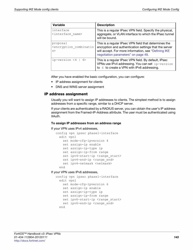
Supporting IKE Mode config clients Configuring IKE Mode Config
F
0
h
After you have enabled the basic configuration, you can configure:
• IP address assignment for clients
• DNS and WINS server assignment
IP address assignmentUsually you will want to assign IP addresses to clients. The simplest method is to assign
addresses from a specific range, similar to a DHCP server.
If your clients are authenticated by a RADIUS server, you can obtain the user’s IP address
assignment from the Framed-IP-Address attribute. The user must be authenticated using
XAuth.
To assign IP addresses from an address range
If your VPN uses IPv4 addresses,
config vpn ipsec phase1-interfaceedit vpn1set mode-cfg-ipversion 4set assign-ip enableset assign-ip-type ipset assign-ip-from rangeset ipv4-start-ip <range_start>set ipv4-end-ip <range_end>set ipv4-netmask <netmask>
end
If your VPN uses IPv6 addresses,
config vpn ipsec phase1-interfaceedit vpn1set mode-cfg-ipversion 6set assign-ip enableset assign-ip-type ipset assign-ip-from rangeset ipv6-start-ip <range_start>set ipv6-end-ip <range_end>
end
interface <interface_name>
This is a regular IPsec VPN field. Specify the physical,
aggregate, or VLAN interface to which the IPsec tunnel
will be bound.
proposal <encryption_combination>
This is a regular IPsec VPN field that determines the
encryption and authentication settings that the server
will accept. For more information, see “Defining IKE
negotiation parameters” on page 49.
ip-version <4 | 6> This is a regular IPsec VPN field. By default, IPsec
VPNs use IPv4 addressing. You can set ip-version to 6 to create a VPN with IPv6 addressing.
Variable Description
ortiOS™ Handbook v3: IPsec VPNs
1-434-112804-20120111 143ttp://docs.fortinet.com/
Example: FortiGate unit as IKE Mode Config server Supporting IKE Mode config clients
To assign IP addresses from a RADIUS server
The users must be authenticated by a RADIUS server and assigned to the FortiGate user
group <grpname>. Since the IP address will not be static, type is set to dynamic, and
mode-cfg is enabled. This is IKE Configuration Method so that compatible clients can
configure themselves with settings that the FortiGate unit provides.
config vpn ipsec phase1-interfaceedit vpn1set type dynamicset mode-cfg enableset assign-ip enableset assign-ip-from usrgrpset xauthtype autoset authusrgrp <grpname>
end
Example: FortiGate unit as IKE Mode Config server
In this example, the FortiGate unit assigns IKE Mode Config clients addresses in the
range of 10.11.101.160 through 10.11.101.180. DNS and WINS server addresses are also
provided. The public interface of the FortiGate unit is Port 1.
The ipv4-split-include variable specifies a firewall address that represents the
networks to which the clients will have access. This destination IP address information is
sent to the clients.
Only the CLI fields required for IKE Mode Config are shown here. For detailed information
about these variables, see the FortiGate CLI Reference.
config vpn ipsec phase1-interfaceedit vpn1set ip-version 4set type dynamicset interface port1set proposal 3des-sha1 aes128-sha1set mode-cfg enableset mode-cfg-ipversion 4set assign-ip enableset assign-ip-type ipset assign-ip-from rangeset ipv4-start-ip 10.11.101.160set ipv4-end-ip 10.11.101.180set ipv4-netmask 255.255.255.0set dns-server1 10.11.101.199set dns-server2 66.11.168.195set wins-server1 10.11.101.191set domain exampleset ipv4-split-include OfficeLAN
end
IPsec VPNs for FortiOS 4.0 MR3
144 01-434-112804-20120111
http://docs.fortinet.com/

Supporting IKE Mode config clients Example: FortiGate unit as IKE Mode Config client
F
0
h
Example: FortiGate unit as IKE Mode Config client
In this example, the FortiGate unit connects to a VPN gateway with a static IP address
that can be reached through Port 1. Only the port, gateway and proposal information
needs to be configured. All other configuration information will come from the IKE Mode
Config server.
config vpn ipsec phase1-interfaceedit vpn1set ip-version 4set type staticset remote-gw <gw_address>set interface port 1set proposal 3des-sha1 aes128-sha1set mode-cfg enableset mode-cfg-ipversion 4set assign-ip enable
end
ortiOS™ Handbook v3: IPsec VPNs
1-434-112804-20120111 145ttp://docs.fortinet.com/

Example: FortiGate unit as IKE Mode Config client Supporting IKE Mode config clients
IPsec VPNs for FortiOS 4.0 MR3
146 01-434-112804-20120111
http://docs.fortinet.com/
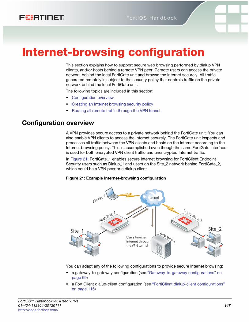
F o r t i O S H a n d b o o k
F
0
h
Internet-browsing configurationThis section explains how to support secure web browsing performed by dialup VPN
clients, and/or hosts behind a remote VPN peer. Remote users can access the private
network behind the local FortiGate unit and browse the Internet securely. All traffic
generated remotely is subject to the security policy that controls traffic on the private
network behind the local FortiGate unit.
The following topics are included in this section:
• Configuration overview
• Creating an Internet browsing security policy
• Routing all remote traffic through the VPN tunnel
Configuration overview
A VPN provides secure access to a private network behind the FortiGate unit. You can
also enable VPN clients to access the Internet securely. The FortiGate unit inspects and
processes all traffic between the VPN clients and hosts on the Internet according to the
Internet browsing policy. This is accomplished even though the same FortiGate interface
is used for both encrypted VPN client traffic and unencrypted Internet traffic.
In Figure 21, FortiGate_1 enables secure Internet browsing for FortiClient Endpoint
Security users such as Dialup_1 and users on the Site_2 network behind FortiGate_2,
which could be a VPN peer or a dialup client.
Figure 21: Example Internet-browsing configuration
You can adapt any of the following configurations to provide secure Internet browsing:
• a gateway-to-gateway configuration (see “Gateway-to-gateway configurations” on
page 69)
• a FortiClient dialup-client configuration (see “FortiClient dialup-client configurations”
on page 115)
FG_Dialup_2
Web server
FortiGate_1
Dialup_1
Site_1Users browseinternet throughthe VPN tunnel
Site_2
FortiGate_ _Dialup_2
ortiOS™ Handbook v3: IPsec VPNs
1-434-112804-20120111 147ttp://docs.fortinet.com/

Creating an Internet browsing security policy Internet-browsing configuration
• a FortiGate dialup-client configuration (see “FortiGate dialup-client configurations” on
page 133)
The procedures in this section assume that one of these configurations is in place, and
that it is operating properly.
To create an internet-browsing configuration based on an existing gateway-to-gateway
configuration, you must edit the gateway-to-gateway configuration as follows:
• On the FortiGate unit that will provide Internet access, create an Internet browsing
security policy. See “Creating an Internet browsing security policy”, below.
• Configure the remote peer or client to route all traffic through the VPN tunnel. You can
do this on a FortiGate unit or on a FortiClient Endpoint Security application. See
“Routing all remote traffic through the VPN tunnel” on page 149.
Creating an Internet browsing security policy
On the FortiGate unit that acts as a VPN server and will provide secure access to the
Internet, you must create an Internet browsing security policy. This policy differs
depending on whether your gateway-to-gateway configuration is policy-based or route-
based.
To create an Internet browsing policy - policy-based VPN
1 Go to Policy > Policy > Policy.
2 Select Create New, enter the following information and then select OK:
Source Interface The interface to which the VPN tunnel is bound.
Source Address Name All
Destination Interface The interface to which the VPN tunnel is bound.
Destination Address NameThe internal range of address of the remote spoke
site.
Schedule As required.
Service As required.
Action IPSEC
VPN TunnelSelect the tunnel that provides access to the private
network behind the FortiGate unit.
UTMSelect the UTM feature profiles that you want to apply
to Internet access.
Allow Inbound Enable
Allow Outbound Enable
Inbound NAT Enable
IPsec VPNs for FortiOS 4.0 MR3
148 01-434-112804-20120111
http://docs.fortinet.com/
Internet-browsing configuration Routing all remote traffic through the VPN tunnel
F
0
h
To create an Internet browsing policy - route-based VPN
1 Go to Policy > Policy > Policy.
2 Select Create New, enter the following information and then select OK:
The VPN clients must be configured to route all Internet traffic through the VPN tunnel.
Routing all remote traffic through the VPN tunnel
To make use of the Internet browsing configuration on the VPN server, the VPN peer or
client must route all traffic through the VPN tunnel. Usually, only the traffic destined for
the private network behind the FortiGate VPN server is sent through the tunnel.
The remote end of the VPN can be a FortiGate unit that acts as a peer in a gateway-to-
gateway configuration or a FortiClient Endpoint Security application that protects an
individual client such as a notebook PC.
• To configure a remote peer FortiGate unit for Internet browsing via VPN, see
“Configuring a FortiGate remote peer to support Internet browsing”.
• To configure a FortiClient Endpoint Security application for Internet browsing via VPN,
see “Configuring a FortiClient application to support Internet browsing” on page 150.
These procedures assume that your VPN connection to the protected private network is
working and that you have configured the FortiGate VPN server for Internet browsing as
described in “Creating an Internet browsing security policy” on page 148.
Configuring a FortiGate remote peer to support Internet browsing
The configuration changes to send all traffic through the VPN differ for policy-based and
route-based VPNs.
To route all traffic through a policy-based VPN
1 At the FortiGate dialup client, go to Policy > Policy > Policy.
2 Select the IPsec security policy and then select Edit.
3 From the Destination Address list, select all.
4 Select OK.
All packets are routed through the VPN tunnel, not just packets destined for the
protected private network.
Source Interface The IPsec VPN interface.
Source Address Name All
Destination Interface
The interface that connects to the Internet. The virtual
IPsec interface is configured on this physical
interface.
Destination Address Name All
Schedule As required.
Service As required.
Action ACCEPT
NAT Enable
UTMSelect the UTM features that you want to apply to
Internet access.
ortiOS™ Handbook v3: IPsec VPNs
1-434-112804-20120111 149ttp://docs.fortinet.com/
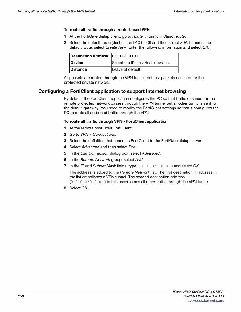
Routing all remote traffic through the VPN tunnel Internet-browsing configuration
To route all traffic through a route-based VPN
1 At the FortiGate dialup client, go to Router > Static > Static Route.
2 Select the default route (destination IP 0.0.0.0) and then select Edit. If there is no
default route, select Create New. Enter the following information and select OK:
All packets are routed through the VPN tunnel, not just packets destined for the
protected private network.
Configuring a FortiClient application to support Internet browsing
By default, the FortiClient application configures the PC so that traffic destined for the
remote protected network passes through the VPN tunnel but all other traffic is sent to
the default gateway. You need to modify the FortiClient settings so that it configures the
PC to route all outbound traffic through the VPN.
To route all traffic through VPN - FortiClient application
1 At the remote host, start FortiClient.
2 Go to VPN > Connections.
3 Select the definition that connects FortiClient to the FortiGate dialup server.
4 Select Advanced and then select Edit.
5 In the Edit Connection dialog box, select Advanced.
6 In the Remote Network group, select Add.
7 In the IP and Subnet Mask fields, type 0.0.0.0/0.0.0.0 and select OK.
The address is added to the Remote Network list. The first destination IP address in
the list establishes a VPN tunnel. The second destination address
(0.0.0.0/0.0.0.0 in this case) forces all other traffic through the VPN tunnel.
8 Select OK.
Destination IP/Mask 0.0.0.0/0.0.0.0
Device Select the IPsec virtual interface.
Distance Leave at default.
IPsec VPNs for FortiOS 4.0 MR3
150 01-434-112804-20120111
http://docs.fortinet.com/
F o r t i O S H a n d b o o k
F
0
h
Redundant VPN configurationsThis section discusses the options for supporting redundant and partially redundant
IPsec VPNs, using route-based approaches.
The following topics are included in this section:
• Configuration overview
• General configuration steps
• Configure the VPN peers - route-based VPN
• Redundant route-based VPN configuration example
• Partially-redundant route-based VPN example
• Creating a backup IPsec interface
Configuration overview
A FortiGate unit with two interfaces connected to the Internet can be configured to
support redundant VPNs to the same remote peer. If the primary connection fails, the
FortiGate unit can establish a VPN using the other connection.
A fully-redundant configuration requires redundant connections to the Internet on both
peers. Figure 22 on page 152 shows an example of this. This is useful to create a reliable
connection between two FortiGate units with static IP addresses.
When only one peer has redundant connections, the configuration is partially-redundant.
For an example of this, see “Partially-redundant route-based VPN example” on page 166.
This is useful to provide reliable service from a FortiGate unit with static IP addresses that
accepts connections from dialup IPsec VPN clients.
In a fully-redundant VPN configuration with two interfaces on each peer, four distinct
paths are possible for VPN traffic from end to end. Each interface on a peer can
communicate with both interfaces on the other peer. This ensures that a VPN will be
available as long as each peer has one working connection to the Internet.
You configure a VPN and an entry in the routing table for each of the four paths. All of
these VPNs are ready to carry data. You set different routing distances for each route and
only the shortest distance route is used. If this route fails, the route with the next shortest
distance is used.
The redundant configurations described in this chapter use route-based VPNs, otherwise
known as virtual IPsec interfaces. This means that the FortiGate unit must operate in NAT
mode. You must use auto-keying. A VPN that is created using manual keys (see “Manual-
key configurations” on page 183) cannot be included in a redundant-tunnel configuration.
Redundant tunnels do not support Tunnel Mode or Manual Keys. You must use Interface
Mode.
ortiOS™ Handbook v3: IPsec VPNs
1-434-112804-20120111 151ttp://docs.fortinet.com/

Configuration overview Redundant VPN configurations
The configuration described here assumes that your redundant VPNs are essentially
equal in cost and capability. When the original VPN returns to service, traffic continues to
use the replacement VPN until the replacement VPN fails. If your redundant VPN uses
more expensive facilities, you want to use it only as a backup while the main VPN is
down. For information on how to do this, see “Creating a backup IPsec interface” on
page 173.
Figure 22: Example redundant-tunnel configuration
General configuration steps
A redundant configuration at each VPN peer includes:
• one phase 1 configuration (virtual IPsec interface) for each path between the two
peers. In a fully-meshed redundant configuration, each network interface on one peer
can communicate with each network interface on the remote peer. If both peers have
two public interfaces, this means that each peer has four paths, for example.
• one phase 2 definition for each phase 1 configuration
• one static route for each IPsec interface, with different distance values to prioritize the
routes
• two Accept security policies per IPsec interface, one for each direction of traffic
• dead peer detection enabled in each phase 1 definition
The procedures in this section assume that two separate interfaces to the Internet are
available on each VPN peer.
FortiGate_2FortiG
ate_1
Site_1
Primary tunnelRedundant tunnel
Site_2FortiG
ate_ rtiGate_2
A VPN that is created using manual keys (see “Manual-key configurations” on page 183)
cannot be included in a redundant-tunnel configuration.
IPsec VPNs for FortiOS 4.0 MR3
152 01-434-112804-20120111
http://docs.fortinet.com/
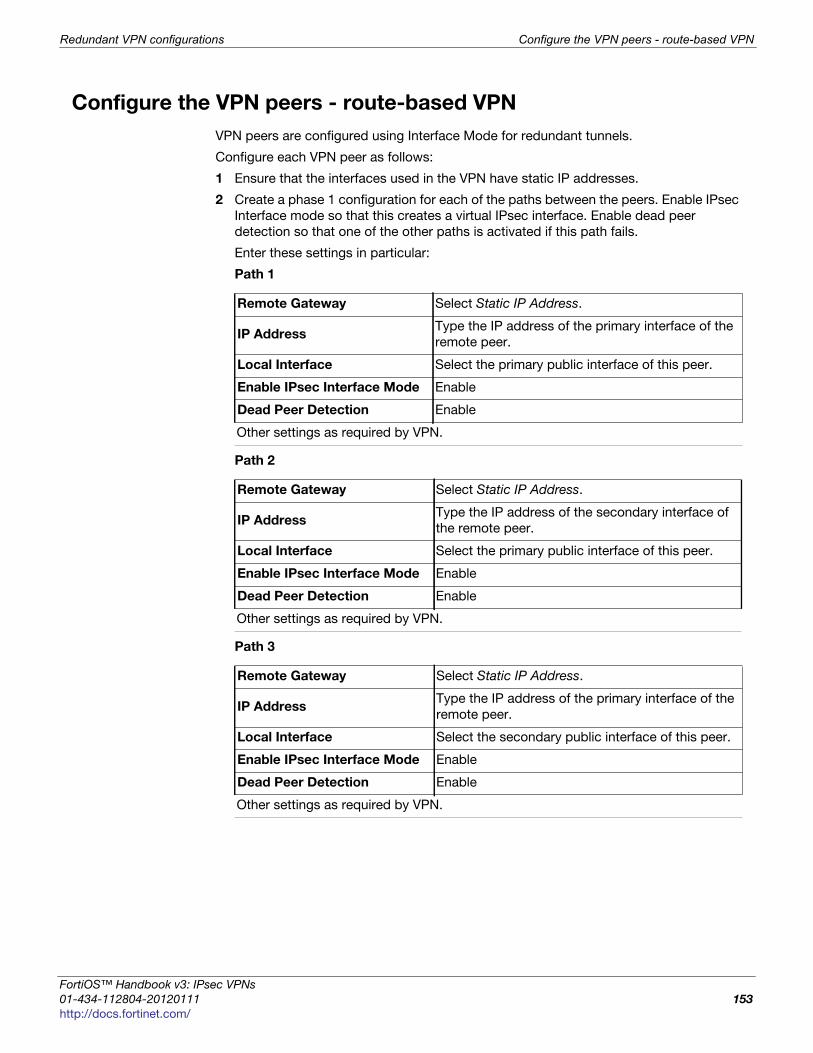
Redundant VPN configurations Configure the VPN peers - route-based VPN
F
0
h
Configure the VPN peers - route-based VPN
VPN peers are configured using Interface Mode for redundant tunnels.
Configure each VPN peer as follows:
1 Ensure that the interfaces used in the VPN have static IP addresses.
2 Create a phase 1 configuration for each of the paths between the peers. Enable IPsec
Interface mode so that this creates a virtual IPsec interface. Enable dead peer
detection so that one of the other paths is activated if this path fails.
Enter these settings in particular:
Path 1
Path 2
Path 3
Remote Gateway Select Static IP Address.
IP AddressType the IP address of the primary interface of the
remote peer.
Local Interface Select the primary public interface of this peer.
Enable IPsec Interface Mode Enable
Dead Peer Detection Enable
Other settings as required by VPN.
Remote Gateway Select Static IP Address.
IP AddressType the IP address of the secondary interface of
the remote peer.
Local Interface Select the primary public interface of this peer.
Enable IPsec Interface Mode Enable
Dead Peer Detection Enable
Other settings as required by VPN.
Remote Gateway Select Static IP Address.
IP AddressType the IP address of the primary interface of the
remote peer.
Local Interface Select the secondary public interface of this peer.
Enable IPsec Interface Mode Enable
Dead Peer Detection Enable
Other settings as required by VPN.
ortiOS™ Handbook v3: IPsec VPNs
1-434-112804-20120111 153ttp://docs.fortinet.com/
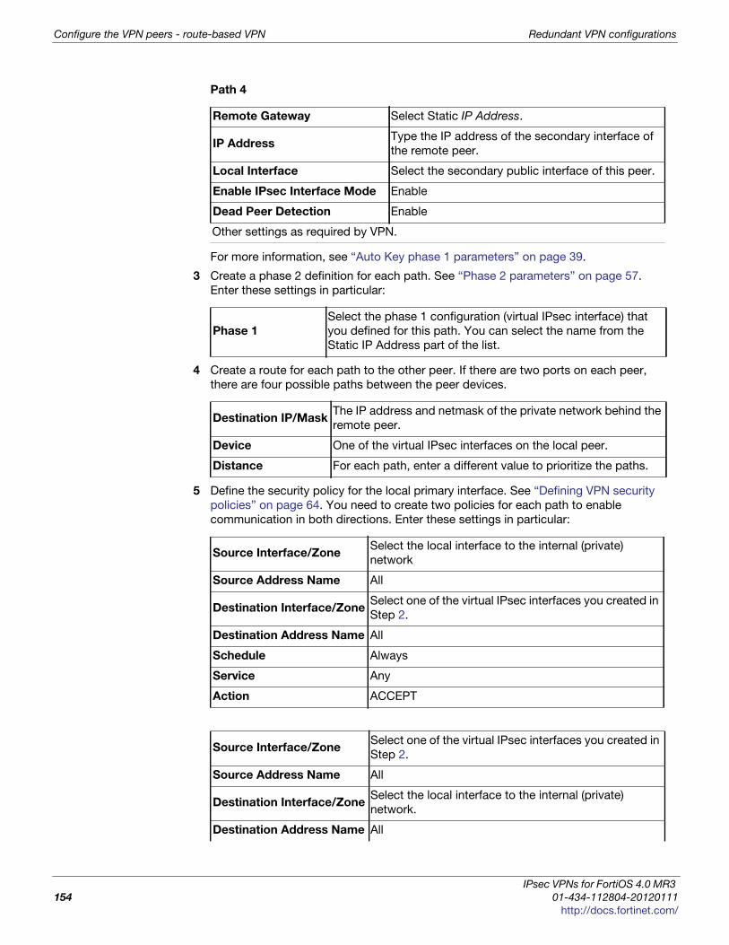
Configure the VPN peers - route-based VPN Redundant VPN configurations
Path 4
For more information, see “Auto Key phase 1 parameters” on page 39.
3 Create a phase 2 definition for each path. See “Phase 2 parameters” on page 57.
Enter these settings in particular:
4 Create a route for each path to the other peer. If there are two ports on each peer,
there are four possible paths between the peer devices.
5 Define the security policy for the local primary interface. See “Defining VPN security
policies” on page 64. You need to create two policies for each path to enable
communication in both directions. Enter these settings in particular:
Remote Gateway Select Static IP Address.
IP AddressType the IP address of the secondary interface of
the remote peer.
Local Interface Select the secondary public interface of this peer.
Enable IPsec Interface Mode Enable
Dead Peer Detection Enable
Other settings as required by VPN.
Phase 1
Select the phase 1 configuration (virtual IPsec interface) that
you defined for this path. You can select the name from the
Static IP Address part of the list.
Destination IP/MaskThe IP address and netmask of the private network behind the
remote peer.
Device One of the virtual IPsec interfaces on the local peer.
Distance For each path, enter a different value to prioritize the paths.
Source Interface/ZoneSelect the local interface to the internal (private)
network
Source Address Name All
Destination Interface/ZoneSelect one of the virtual IPsec interfaces you created in
Step 2.
Destination Address Name All
Schedule Always
Service Any
Action ACCEPT
Source Interface/ZoneSelect one of the virtual IPsec interfaces you created in
Step 2.
Source Address Name All
Destination Interface/ZoneSelect the local interface to the internal (private)
network.
Destination Address Name All
IPsec VPNs for FortiOS 4.0 MR3
154 01-434-112804-20120111
http://docs.fortinet.com/

Redundant VPN configurations Redundant route-based VPN configuration example
F
0
h
6 Place the policy in the policy list above any other policies having similar source and
destination addresses.
7 Repeat this procedure at the remote FortiGate unit.
Redundant route-based VPN configuration example
This example demonstrates a fully redundant site-to-site VPN configuration using route-
based VPNs. At each site, the FortiGate unit has two interfaces connected to the Internet
through different ISPs. This means that there are four possible paths for communication
between the two units. In this example, these paths, listed in descending priority, are:
• FortiGate_1 WAN 1 to FortiGate_2 WAN 1
• FortiGate_1 WAN 1 to FortiGate_2 WAN 2
• FortiGate_1 WAN 2 to FortiGate_2 WAN 1
• FortiGate_1 WAN 2 to FortiGate_2 WAN 2
Figure 23: Example redundant route-based VPN configuration
For each path, VPN configuration, security policies and routing are defined. By specifying
a different routing distance for each path, the paths are prioritized. A VPN tunnel is
established on each path, but only the highest priority one is used. If the highest priority
path goes down, the traffic is automatically routed over the next highest priority path. You
could use dynamic routing, but to keep this example simple, static routing is used.
Configuring FortiGate_1
You must
• configure the interfaces involved in the VPN
• define the phase 1 configuration for each of the four possible paths, creating a virtual
IPsec interface for each one
• define the phase 2 configuration for each of the four possible paths
• configure routes for the four IPsec interfaces, assigning the appropriate priorities
Schedule Always
Service Any
Action ACCEPT
WAN1 192.168.10.2
WAN2172.16.20.2
WAN1
192.168.20.2
WAN2
172.16.30.2
Finance network10.21.101.0/24
HR network10.31.101.0/24
Primary tunnel
FortiGate_1FortiGate_2
Redundant tunnel
WW11
e_1 2
F
ortiOS™ Handbook v3: IPsec VPNs
1-434-112804-20120111 155ttp://docs.fortinet.com/
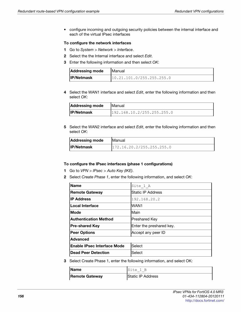
Redundant route-based VPN configuration example Redundant VPN configurations
• configure incoming and outgoing security policies between the internal interface and
each of the virtual IPsec interfaces
To configure the network interfaces
1 Go to System > Network > Interface.
2 Select the the Internal interface and select Edit.
3 Enter the following information and then select OK:
4 Select the WAN1 interface and select Edit, enter the following information and then
select OK:
5 Select the WAN2 interface and select Edit, enter the following information and then
select OK:
To configure the IPsec interfaces (phase 1 configurations)
1 Go to VPN > IPsec > Auto Key (IKE).
2 Select Create Phase 1, enter the following information, and select OK:
3 Select Create Phase 1, enter the following information, and select OK:
Addressing mode Manual
IP/Netmask 10.21.101.0/255.255.255.0
Addressing mode Manual
IP/Netmask 192.168.10.2/255.255.255.0
Addressing mode Manual
IP/Netmask 172.16.20.2/255.255.255.0
Name Site_1_A
Remote Gateway Static IP Address
IP Address 192.168.20.2
Local Interface WAN1
Mode Main
Authentication Method Preshared Key
Pre-shared Key Enter the preshared key.
Peer Options Accept any peer ID
Advanced
Enable IPsec Interface Mode Select
Dead Peer Detection Select
Name Site_1_B
Remote Gateway Static IP Address
IPsec VPNs for FortiOS 4.0 MR3
156 01-434-112804-20120111
http://docs.fortinet.com/
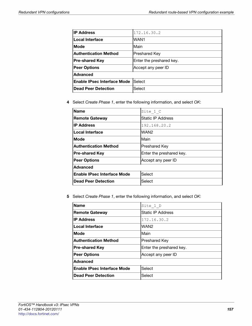
Redundant VPN configurations Redundant route-based VPN configuration example
F
0
h
4 Select Create Phase 1, enter the following information, and select OK:
5 Select Create Phase 1, enter the following information, and select OK:
IP Address 172.16.30.2
Local Interface WAN1
Mode Main
Authentication Method Preshared Key
Pre-shared Key Enter the preshared key.
Peer Options Accept any peer ID
Advanced
Enable IPsec Interface Mode Select
Dead Peer Detection Select
Name Site_1_C
Remote Gateway Static IP Address
IP Address 192.168.20.2
Local Interface WAN2
Mode Main
Authentication Method Preshared Key
Pre-shared Key Enter the preshared key.
Peer Options Accept any peer ID
Advanced
Enable IPsec Interface Mode Select
Dead Peer Detection Select
Name Site_1_D
Remote Gateway Static IP Address
IP Address 172.16.30.2
Local Interface WAN2
Mode Main
Authentication Method Preshared Key
Pre-shared Key Enter the preshared key.
Peer Options Accept any peer ID
Advanced
Enable IPsec Interface Mode Select
Dead Peer Detection Select
ortiOS™ Handbook v3: IPsec VPNs
1-434-112804-20120111 157ttp://docs.fortinet.com/
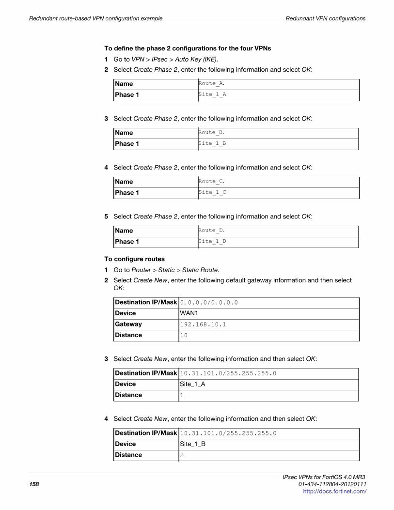
Redundant route-based VPN configuration example Redundant VPN configurations
To define the phase 2 configurations for the four VPNs
1 Go to VPN > IPsec > Auto Key (IKE).
2 Select Create Phase 2, enter the following information and select OK:
3 Select Create Phase 2, enter the following information and select OK:
4 Select Create Phase 2, enter the following information and select OK:
5 Select Create Phase 2, enter the following information and select OK:
To configure routes
1 Go to Router > Static > Static Route.
2 Select Create New, enter the following default gateway information and then select
OK:
3 Select Create New, enter the following information and then select OK:
4 Select Create New, enter the following information and then select OK:
Name Route_A.
Phase 1 Site_1_A
Name Route_B.
Phase 1 Site_1_B
Name Route_C.
Phase 1 Site_1_C
Name Route_D.
Phase 1 Site_1_D
Destination IP/Mask 0.0.0.0/0.0.0.0
Device WAN1
Gateway 192.168.10.1
Distance 10
Destination IP/Mask 10.31.101.0/255.255.255.0
Device Site_1_A
Distance 1
Destination IP/Mask 10.31.101.0/255.255.255.0
Device Site_1_B
Distance 2
IPsec VPNs for FortiOS 4.0 MR3
158 01-434-112804-20120111
http://docs.fortinet.com/
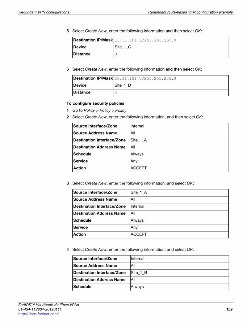
Redundant VPN configurations Redundant route-based VPN configuration example
F
0
h
5 Select Create New, enter the following information and then select OK:
6 Select Create New, enter the following information and then select OK:
To configure security policies
1 Go to Policy > Policy > Policy.
2 Select Create New, enter the following information, and then select OK:
3 Select Create New, enter the following information, and select OK:
4 Select Create New, enter the following information, and select OK:
Destination IP/Mask 10.31.101.0/255.255.255.0
Device Site_1_C
Distance 3
Destination IP/Mask 10.31.101.0/255.255.255.0
Device Site_1_D
Distance 4
Source Interface/Zone Internal
Source Address Name All
Destination Interface/Zone Site_1_A
Destination Address Name All
Schedule Always
Service Any
Action ACCEPT
Source Interface/Zone Site_1_A
Source Address Name All
Destination Interface/Zone Internal
Destination Address Name All
Schedule Always
Service Any
Action ACCEPT
Source Interface/Zone Internal
Source Address Name All
Destination Interface/Zone Site_1_B
Destination Address Name All
Schedule Always
ortiOS™ Handbook v3: IPsec VPNs
1-434-112804-20120111 159ttp://docs.fortinet.com/

Redundant route-based VPN configuration example Redundant VPN configurations
5 Select Create New, enter the following information, and select OK:
6 Select Create New, enter the following information, and select OK:
7 Select Create New, enter the following information, and select OK:
8 Select Create New, enter the following information, and select OK:
Service Any
Action ACCEPT
Source Interface/Zone Site_1_B
Source Address Name All
Destination Interface/Zone Internal
Destination Address Name All
Schedule Always
Service Any
Action ACCEPT
Source Interface/Zone Internal
Source Address Name All
Destination Interface/Zone Site_1_C
Destination Address Name All
Schedule Always
Service Any
Action ACCEPT
Source Interface/Zone Site_1_C
Source Address Name All
Destination Interface/Zone Internal
Destination Address Name All
Schedule Always
Service Any
Action ACCEPT
Source Interface/Zone Internal
Source Address Name All
Destination Interface/Zone Site_1_D
Destination Address Name All
Schedule Always
IPsec VPNs for FortiOS 4.0 MR3
160 01-434-112804-20120111
http://docs.fortinet.com/

Redundant VPN configurations Redundant route-based VPN configuration example
F
0
h
9 Select Create New, enter the following information, and select OK:
Configuring FortiGate_2
The configuration for FortiGate_2 is very similar that of FortiGate_1. You must
• configure the interfaces involved in the VPN
• define the phase 1 configuration for each of the four possible paths, creating a virtual
IPsec interface for each one
• define the phase 2 configuration for each of the four possible paths
• configure routes for the four IPsec interfaces, assigning the appropriate priorities
• configure incoming and outgoing security policies between the internal interface and
each of the virtual IPsec interfaces
To configure the network interfaces
1 Go to System > Network > Interface.
2 Select the Internal interface and then select Edit. Enter the following information and
then select OK:
3 Select the WAN1 interface and then select Edit. Enter the following information and
then select OK:
4 Select the WAN2 interface and then select Edit. Enter the following information and
then select OK:
To configure the IPsec interfaces (phase 1 configurations)
1 Go to VPN > IPsec > Auto Key (IKE).
Service Any
Action ACCEPT
Source Interface/Zone Site_1_D
Source Address Name All
Destination Interface/Zone Internal
Destination Address Name All
Schedule Always
Service Any
Action ACCEPT
Addressing mode Manual
IP/Netmask 10.31.101.0/255.255.255.0
Addressing mode Manual
IP/Netmask 192.168.20.2/255.255.255.0
Addressing mode Manual
IP/Netmask 172.16.30.2/255.255.255.0
ortiOS™ Handbook v3: IPsec VPNs
1-434-112804-20120111 161ttp://docs.fortinet.com/

Redundant route-based VPN configuration example Redundant VPN configurations
2 Select Create Phase 1, enter the following information, and select OK:
3 Select Create Phase 1, enter the following information, and select OK:
4 Select Create Phase 1, enter the following information, and select OK:
Name Site_2_A
Remote Gateway Static IP Address
IP Address 192.168.10.2
Local Interface WAN1
Mode Main
Authentication Method Preshared Key
Pre-shared Key Enter the preshared key.
Peer Options Accept any peer ID
Advanced
Enable IPsec Interface Mode Select
Dead Peer Detection Select
Name Site_2_B
Remote Gateway Static IP Address
IP Address 172.16.20.2
Local Interface WAN1
Mode Main
Authentication Method Preshared Key
Pre-shared Key Enter the preshared key.
Peer Options Accept any peer ID
Advanced
Enable IPsec Interface Mode Select
Dead Peer Detection Select
Name Site_2_C
Remote Gateway Static IP Address
IP Address 192.168.10.2
Local Interface WAN2
Mode Main
Authentication Method Preshared Key
Pre-shared Key Enter the preshared key.
Peer Options Accept any peer ID
Advanced
IPsec VPNs for FortiOS 4.0 MR3
162 01-434-112804-20120111
http://docs.fortinet.com/
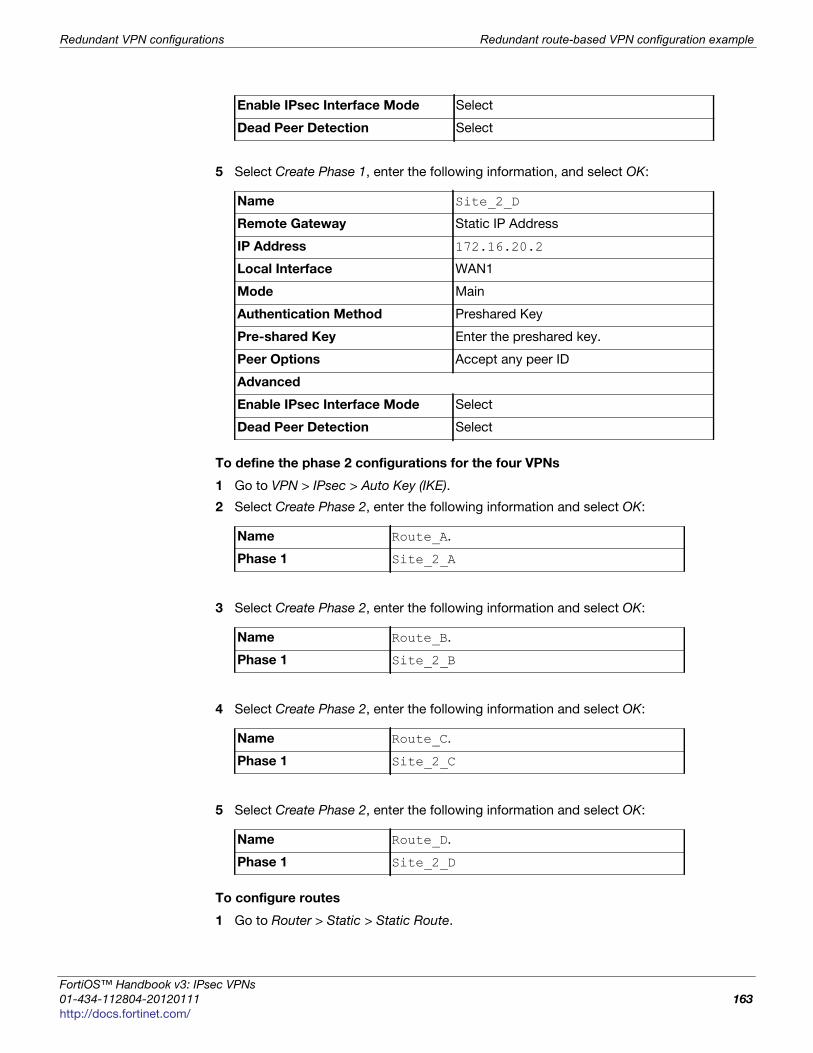
Redundant VPN configurations Redundant route-based VPN configuration example
F
0
h
5 Select Create Phase 1, enter the following information, and select OK:
To define the phase 2 configurations for the four VPNs
1 Go to VPN > IPsec > Auto Key (IKE).
2 Select Create Phase 2, enter the following information and select OK:
3 Select Create Phase 2, enter the following information and select OK:
4 Select Create Phase 2, enter the following information and select OK:
5 Select Create Phase 2, enter the following information and select OK:
To configure routes
1 Go to Router > Static > Static Route.
Enable IPsec Interface Mode Select
Dead Peer Detection Select
Name Site_2_D
Remote Gateway Static IP Address
IP Address 172.16.20.2
Local Interface WAN1
Mode Main
Authentication Method Preshared Key
Pre-shared Key Enter the preshared key.
Peer Options Accept any peer ID
Advanced
Enable IPsec Interface Mode Select
Dead Peer Detection Select
Name Route_A.
Phase 1 Site_2_A
Name Route_B.
Phase 1 Site_2_B
Name Route_C.
Phase 1 Site_2_C
Name Route_D.
Phase 1 Site_2_D
ortiOS™ Handbook v3: IPsec VPNs
1-434-112804-20120111 163ttp://docs.fortinet.com/
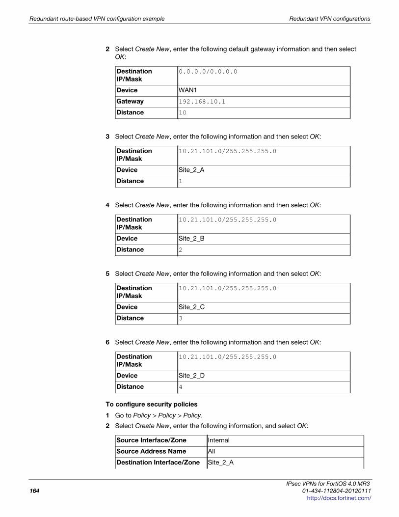
Redundant route-based VPN configuration example Redundant VPN configurations
2 Select Create New, enter the following default gateway information and then select
OK:
3 Select Create New, enter the following information and then select OK:
4 Select Create New, enter the following information and then select OK:
5 Select Create New, enter the following information and then select OK:
6 Select Create New, enter the following information and then select OK:
To configure security policies
1 Go to Policy > Policy > Policy.
2 Select Create New, enter the following information, and select OK:
Destination
IP/Mask
0.0.0.0/0.0.0.0
Device WAN1
Gateway 192.168.10.1
Distance 10
Destination
IP/Mask
10.21.101.0/255.255.255.0
Device Site_2_A
Distance 1
Destination
IP/Mask
10.21.101.0/255.255.255.0
Device Site_2_B
Distance 2
Destination
IP/Mask
10.21.101.0/255.255.255.0
Device Site_2_C
Distance 3
Destination
IP/Mask
10.21.101.0/255.255.255.0
Device Site_2_D
Distance 4
Source Interface/Zone Internal
Source Address Name All
Destination Interface/Zone Site_2_A
IPsec VPNs for FortiOS 4.0 MR3
164 01-434-112804-20120111
http://docs.fortinet.com/
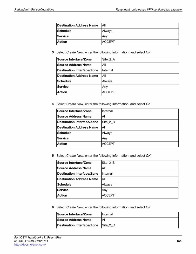
Redundant VPN configurations Redundant route-based VPN configuration example
F
0
h
3 Select Create New, enter the following information, and select OK:
4 Select Create New, enter the following information, and select OK:
5 Select Create New, enter the following information, and select OK:
6 Select Create New, enter the following information, and select OK:
Destination Address Name All
Schedule Always
Service Any
Action ACCEPT
Source Interface/Zone Site_2_A
Source Address Name All
Destination Interface/Zone Internal
Destination Address Name All
Schedule Always
Service Any
Action ACCEPT
Source Interface/Zone Internal
Source Address Name All
Destination Interface/Zone Site_2_B
Destination Address Name All
Schedule Always
Service Any
Action ACCEPT
Source Interface/Zone Site_2_B
Source Address Name All
Destination Interface/Zone Internal
Destination Address Name All
Schedule Always
Service Any
Action ACCEPT
Source Interface/Zone Internal
Source Address Name All
Destination Interface/Zone Site_2_C
ortiOS™ Handbook v3: IPsec VPNs
1-434-112804-20120111 165ttp://docs.fortinet.com/
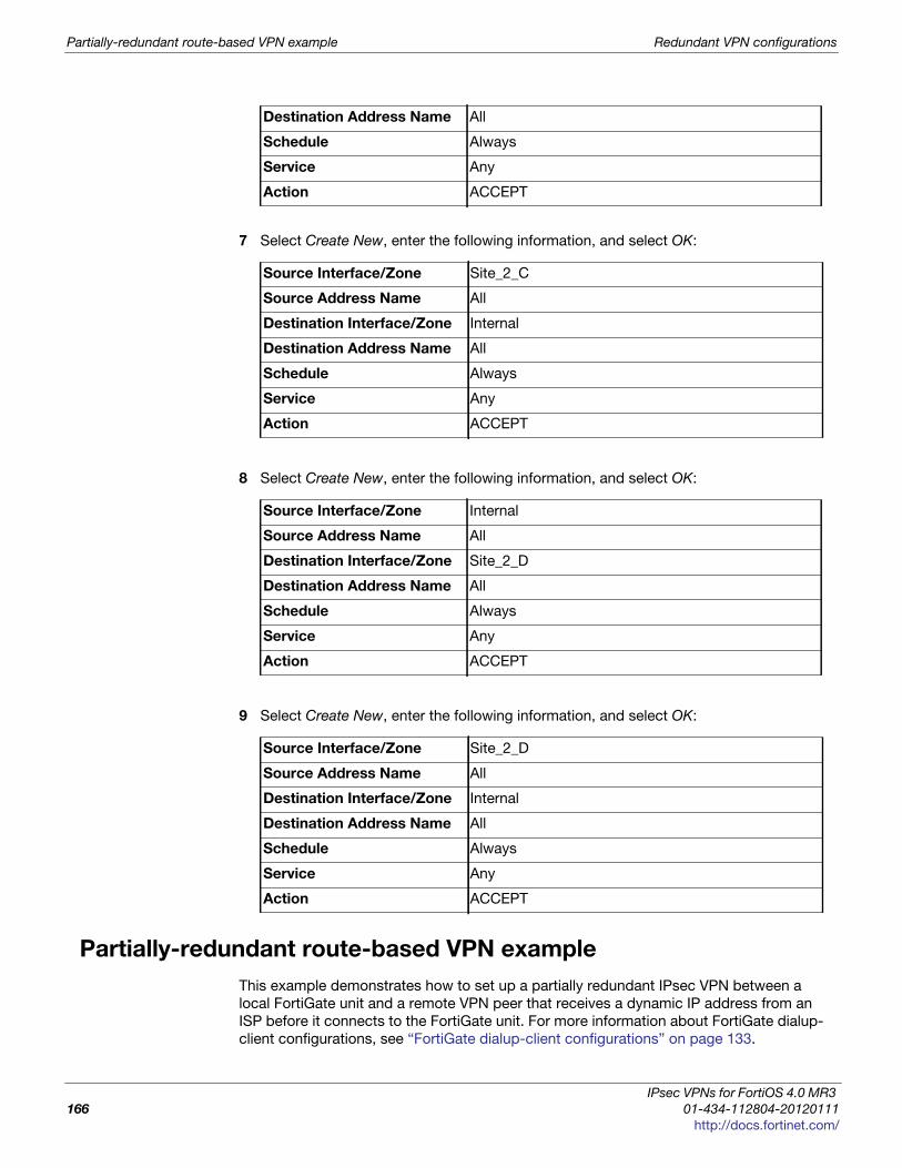
Partially-redundant route-based VPN example Redundant VPN configurations
7 Select Create New, enter the following information, and select OK:
8 Select Create New, enter the following information, and select OK:
9 Select Create New, enter the following information, and select OK:
Partially-redundant route-based VPN example
This example demonstrates how to set up a partially redundant IPsec VPN between a
local FortiGate unit and a remote VPN peer that receives a dynamic IP address from an
ISP before it connects to the FortiGate unit. For more information about FortiGate dialup-
client configurations, see “FortiGate dialup-client configurations” on page 133.
Destination Address Name All
Schedule Always
Service Any
Action ACCEPT
Source Interface/Zone Site_2_C
Source Address Name All
Destination Interface/Zone Internal
Destination Address Name All
Schedule Always
Service Any
Action ACCEPT
Source Interface/Zone Internal
Source Address Name All
Destination Interface/Zone Site_2_D
Destination Address Name All
Schedule Always
Service Any
Action ACCEPT
Source Interface/Zone Site_2_D
Source Address Name All
Destination Interface/Zone Internal
Destination Address Name All
Schedule Always
Service Any
Action ACCEPT
IPsec VPNs for FortiOS 4.0 MR3
166 01-434-112804-20120111
http://docs.fortinet.com/

Redundant VPN configurations Partially-redundant route-based VPN example
F
0
h
When a FortiGate unit has more than one interface to the Internet (see FortiGate_1 in
Figure 24), you can configure redundant routes—if the primary connection fails, the
FortiGate unit can establish a VPN using the redundant connection.
In this case, FortiGate_2 has only one connection to the Internet. If the link to the ISP
were to go down, the connection to FortiGate_1 would be lost, and the tunnel would be
taken down. The tunnel is said to be partially redundant because FortiGate_2 does not
support a redundant connection.
In the configuration example:
• Both FortiGate units operate in NAT mode.
• Two separate interfaces to the Internet (192.168.10.2 and 172.16.20.2) are available
on FortiGate_1. Each interface has a static public IP address.
• FortiGate_2 has a single connection to the Internet and obtains a dynamic public IP
address (for example, 172.16.30.1) when it connects to the Internet.
• FortiGate_2 forwards IP packets from the SOHO network (10.31.101.0/24) to the
corporate network (10.21.101.0/24) behind FortiGate_1 through a partially redundant
IPsec VPN. Encrypted packets from FortiGate_2 are addressed to the public interface
of FortiGate_1. Encrypted packets from FortiGate_1 are addressed to the public IP
address of FortiGate_2.
There are two possible paths for communication between the two units. In this example,
these paths, listed in descending priority, are:
• FortiGate_1 WAN 1 to FortiGate_2 WAN 1
• FortiGate_1 WAN 2 to FortiGate_2 WAN 1
For each path, VPN configuration, security policies and routing are defined. By specifying
a different routing distance for each path, the paths are prioritized. A VPN tunnel is
established on each path, but only the highest priority one is used. If the highest priority
path goes down, the traffic is automatically routed over the next highest priority path. You
could use dynamic routing, but to keep this example simple, static routing is used.
Figure 24: Example partially redundant route-based configuration
WAN1 192.168.10.1
WAN1 172.16.30.1
WAN2172.16.20.2
Corporate network10.21.101.0/24
SOHO network10.31.101.0/24
Primary tunnel
FortiGate_1
FortiGate_2
Redundant tunnel
WW119
_1
Fo
ortiOS™ Handbook v3: IPsec VPNs
1-434-112804-20120111 167ttp://docs.fortinet.com/
Partially-redundant route-based VPN example Redundant VPN configurations
Configuring FortiGate_1
You must
• configure the interfaces involved in the VPN
• define the phase 1 configuration for each of the two possible paths, creating a virtual
IPsec interface for each one
• define the phase 2 configuration for each of the two possible paths
• configure incoming and outgoing security policies between the internal interface and
each of the virtual IPsec interfaces
To configure the network interfaces
1 Go to System > Network > Interface.
2 Select the Internal interface and select Edit. Enter the following information and then
select OK:
3 Select the WAN1 interface and select Edit. Enter the following information and then
select OK:
4 Select the WAN2 interface and select Edit. Enter the following information and then
select OK:
To configure the IPsec interfaces (phase 1 configurations)
1 Go to VPN > IPsec > Auto Key (IKE).
2 Select Create Phase 1, enter the following information, and select OK:
Addressing mode Manual
IP/Netmask 10.21.101.2/255.255.255.0
Addressing mode Manual
IP/Netmask 192.168.10.2/255.255.255.0
Addressing mode Manual
IP/Netmask 172.16.20.2/255.255.255.0
Name Site_1_A
Remote Gateway Dialup User
Local Interface WAN1
Mode Main
Authentication Method Preshared Key
Pre-shared Key Enter the preshared key.
Peer Options Accept any peer ID
Advanced
IPsec VPNs for FortiOS 4.0 MR3
168 01-434-112804-20120111
http://docs.fortinet.com/

Redundant VPN configurations Partially-redundant route-based VPN example
F
0
h
3 Select Create Phase 1, enter the following information, and select OK:
To define the phase 2 configurations for the two VPNs
1 Go to VPN > IPsec > Auto Key (IKE).
2 Select Create Phase 2, enter the following information and select OK:
3 Select Create Phase 2, enter the following information and select OK:
To configure routes
1 Go to Router > Static > Static Route.
2 Select Create New, enter the following default gateway information and then select
OK:
Enable IPsec Interface Mode Select
Dead Peer Detection Select
Name Site_1_B
Remote Gateway Dialup User
Local Interface WAN2
Mode Main
Authentication Method Preshared Key
Pre-shared Key Enter the preshared key.
Peer Options Accept any peer ID
Advanced
Enable IPsec Interface Mode Select
Dead Peer Detection Select
Name Route_A.
Phase 1 Site_1_A
Name Route_B.
Phase 1 Site_1_B
Destination
IP/Mask
0.0.0.0/0.0.0.0
Device WAN1
Gateway 192.168.10.1
Distance 10
ortiOS™ Handbook v3: IPsec VPNs
1-434-112804-20120111 169ttp://docs.fortinet.com/

Partially-redundant route-based VPN example Redundant VPN configurations
To configure security policies
1 Go to Policy > Policy > Policy.
2 Select Create New, enter the following information, and select OK:
3 Select Create New, enter the following information, and select OK:
Configuring FortiGate_2
The configuration for FortiGate_2 is similar to that of FortiGate_1. You must
• configure the interface involved in the VPN
• define the phase 1 configuration for the primary and redundant paths, creating a
virtual IPsec interface for each one
• define the phase 2 configurations for the primary and redundant paths, defining the
internal network as the source address so that FortiGate_1 can automatically
configure routing
• configure the routes for the two IPsec interfaces, assigning the appropriate priorities
• configure security policies between the internal interface and each of the virtual IPsec
interfaces
To configure the network interfaces
1 Go to System > Network > Interface.
2 Select the Internal interface and select Edit. Enter the following information and then
select OK:
Source Interface/Zone Internal
Source Address Name All
Destination Interface/Zone Site_1_A
Destination Address Name All
Schedule Always
Service Any
Action ACCEPT
Source Interface/Zone Internal
Source Address Name All
Destination Interface/Zone Site_1_B
Destination Address Name All
Schedule Always
Service Any
Action ACCEPT
Addressing mode Manual
IP/Netmask 10.31.101.2/255.255.255.0
IPsec VPNs for FortiOS 4.0 MR3
170 01-434-112804-20120111
http://docs.fortinet.com/

Redundant VPN configurations Partially-redundant route-based VPN example
F
0
h
3 Select the WAN1 interface and select Edit. Enter the following information and then
select OK:
To configure the two IPsec interfaces (phase 1 configurations)
1 Go to VPN > IPsec > Auto Key (IKE).
2 Select Create Phase 1, enter the following information, and select OK:
3 Select Create Phase 1, enter the following information, and select OK:
To define the phase 2 configurations for the two VPNs
1 Go to VPN > IPsec > Auto Key (IKE).
2 Select Create Phase 2, enter the following information and select OK:
Addressing mode DHCP
Name Site_2_A
Remote Gateway Static IP Address
IP Address 192.168.10.2
Local Interface WAN1
Mode Main
Authentication Method Preshared Key
Pre-shared Key Enter the preshared key.
Peer Options Accept any peer ID
Advanced
Enable IPsec Interface Mode Select
Dead Peer Detection Select
Name Site_2_B
Remote Gateway Static IP Address
IP Address 172.16.20.2
Local Interface WAN1
Mode Main
Authentication Method Preshared Key
Pre-shared Key Enter the preshared key.
Peer Options Accept any peer ID
Advanced
Enable IPsec Interface Mode Select
Dead Peer Detection Select
ortiOS™ Handbook v3: IPsec VPNs
1-434-112804-20120111 171ttp://docs.fortinet.com/
Partially-redundant route-based VPN example Redundant VPN configurations
3 Select Create Phase 2, enter the following information and select OK:
To configure routes
1 Go to Router > Static > Static Route.
2 Select Create New, enter the following information and then select OK:
3 Select Create New, enter the following information and then select OK:
To configure security policies
1 Go to Policy > Policy > Policy.
2 Select Create New, enter the following information, and select OK:
3 Select Create New, enter the following information, and select OK:
Name Route_A.
Phase 1 Site_2_A
Advanced
Source Address 10.31.101.0/24
Name Route_B.
Phase 1 Site_2_B
Advanced
Source Address 10.31.101.0/24
Destination IP/Mask 10.21.101.0/255.255.255.0
Device Site_2_A
Distance 1
Destination IP/Mask 10.21.101.0/255.255.255.0
Device Site_2_B
Distance 2
Source Interface/Zone Internal
Source Address Name All
Destination Interface/Zone Site_2_A
Destination Address Name All
Schedule Always
Service Any
Action ACCEPT
IPsec VPNs for FortiOS 4.0 MR3
172 01-434-112804-20120111
http://docs.fortinet.com/

Redundant VPN configurations Creating a backup IPsec interface
F
0
h
Creating a backup IPsec interface
You can configure a route-based VPN that acts as a backup facility to another VPN. It is
used only while your main VPN is out of service. This is desirable when the redundant
VPN uses a more expensive facility.
You can configure a backup IPsec interface only in the CLI. The backup feature works
only on interfaces with static addresses that have dead peer detection enabled. The
monitor-phase1 option creates a backup VPN for the specified phase 1 configuration.
In the following example, backup_vpn is a backup for main_vpn.
config vpn ipsec phase1-interfaceedit main_vpnset dpd onset interface port1set nattraversal enableset psksecret "hard-to-guess"set remote-gw 192.168.10.8set type static
endedit backup_vpnset dpd onset interface port2set monitor-phase1 main_vpnset nattraversal enableset psksecret "hard-to-guess"set remote-gw 192.168.10.8set type static
end
Source Interface/Zone Internal
Source Address Name All
Destination Interface/Zone Site_2_B
Destination Address Name All
Schedule Always
Service Any
Action ACCEPT
ortiOS™ Handbook v3: IPsec VPNs
1-434-112804-20120111 173ttp://docs.fortinet.com/

Creating a backup IPsec interface Redundant VPN configurations
IPsec VPNs for FortiOS 4.0 MR3
174 01-434-112804-20120111
http://docs.fortinet.com/
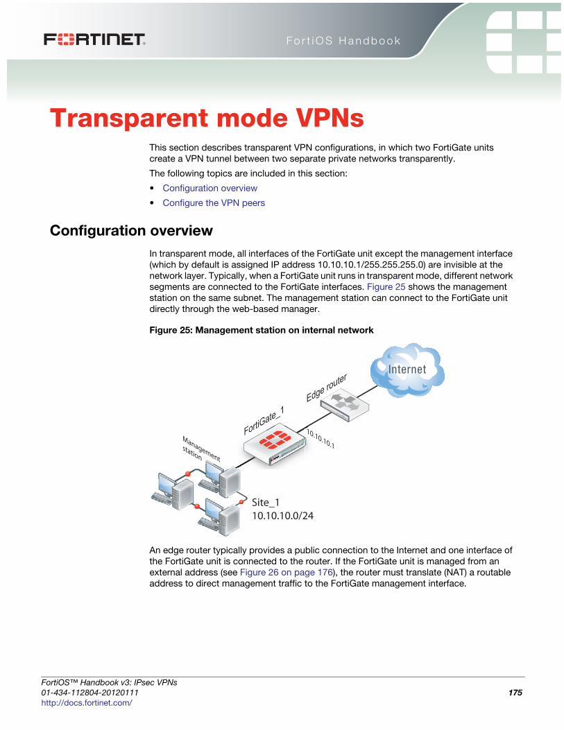
F o r t i O S H a n d b o o k
F
0
h
Transparent mode VPNsThis section describes transparent VPN configurations, in which two FortiGate units
create a VPN tunnel between two separate private networks transparently.
The following topics are included in this section:
• Configuration overview
• Configure the VPN peers
Configuration overview
In transparent mode, all interfaces of the FortiGate unit except the management interface
(which by default is assigned IP address 10.10.10.1/255.255.255.0) are invisible at the
network layer. Typically, when a FortiGate unit runs in transparent mode, different network
segments are connected to the FortiGate interfaces. Figure 25 shows the management
station on the same subnet. The management station can connect to the FortiGate unit
directly through the web-based manager.
Figure 25: Management station on internal network
An edge router typically provides a public connection to the Internet and one interface of
the FortiGate unit is connected to the router. If the FortiGate unit is managed from an
external address (see Figure 26 on page 176), the router must translate (NAT) a routable
address to direct management traffic to the FortiGate management interface.
FortiGate_1
Edge router
FortiG
Site_110.10.10.0/24
Managementstation
10.10.10.1
ortiOS™ Handbook v3: IPsec VPNs
1-434-112804-20120111 175ttp://docs.fortinet.com/
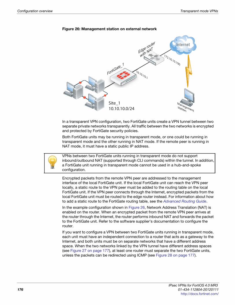
Configuration overview Transparent mode VPNs
Figure 26: Management station on external network
In a transparent VPN configuration, two FortiGate units create a VPN tunnel between two
separate private networks transparently. All traffic between the two networks is encrypted
and protected by FortiGate security policies.
Both FortiGate units may be running in transparent mode, or one could be running in
transparent mode and the other running in NAT mode. If the remote peer is running in
NAT mode, it must have a static public IP address.
Encrypted packets from the remote VPN peer are addressed to the management
interface of the local FortiGate unit. If the local FortiGate unit can reach the VPN peer
locally, a static route to the VPN peer must be added to the routing table on the local
FortiGate unit. If the VPN peer connects through the Internet, encrypted packets from the
local FortiGate unit must be routed to the edge router instead. For information about how
to add a static route to the FortiGate routing table, see the Advanced Routing Guide.
In the example configuration shown in Figure 26, Network Address Translation (NAT) is
enabled on the router. When an encrypted packet from the remote VPN peer arrives at
the router through the Internet, the router performs inbound NAT and forwards the packet
to the FortiGate unit. Refer to the software supplier’s documentation to configure the
router.
If you want to configure a VPN between two FortiGate units running in transparent mode,
each unit must have an independent connection to a router that acts as a gateway to the
Internet, and both units must be on separate networks that have a different address
space. When the two networks linked by the VPN tunnel have different address spaces
(see Figure 27 on page 177), at least one router must separate the two FortiGate units,
unless the packets can be redirected using ICMP (see Figure 28 on page 177).
FortiGate_1
Edge router
with NAT
FortiGa
Site_110.10.10.0/24
Managementstation
10.10.10.1
172.16.10.100
VPNs between two FortiGate units running in transparent mode do not support
inbound/outbound NAT (supported through CLI commands) within the tunnel. In addition,
a FortiGate unit running in transparent mode cannot be used in a hub-and-spoke
configuration.
IPsec VPNs for FortiOS 4.0 MR3
176 01-434-112804-20120111
http://docs.fortinet.com/
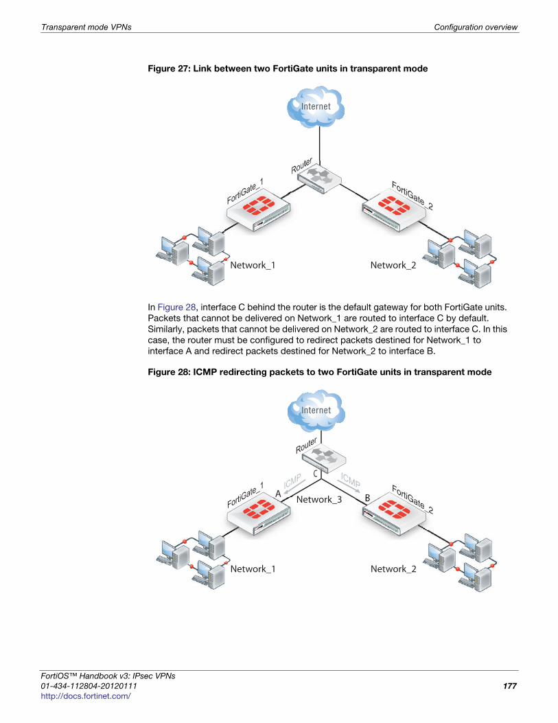
Transparent mode VPNs Configuration overview
F
0
h
Figure 27: Link between two FortiGate units in transparent mode
In Figure 28, interface C behind the router is the default gateway for both FortiGate units.
Packets that cannot be delivered on Network_1 are routed to interface C by default.
Similarly, packets that cannot be delivered on Network_2 are routed to interface C. In this
case, the router must be configured to redirect packets destined for Network_1 to
interface A and redirect packets destined for Network_2 to interface B.
Figure 28: ICMP redirecting packets to two FortiGate units in transparent mode
FortiGate_1
Router
FortiGa
Network_1 Network_2
FortiGate_2
FortiGate_1 ICMP
Router
FortiGa
Network_1
Network_3
Network_2
FortiGate_2
ICMPC
A B
ortiOS™ Handbook v3: IPsec VPNs
1-434-112804-20120111 177ttp://docs.fortinet.com/

Configuration overview Transparent mode VPNs
If there are additional routers behind the FortiGate unit (see Figure 29 on page 178) and
the destination IP address of an inbound packet is on a network behind one of those
routers, the FortiGate routing table must include routes to those networks. For example,
in Figure 29, the FortiGate unit must be configured with static routes to interfaces A and
B in order to forward packets to Network_1 and Network_2 respectively.
Figure 29: Destinations on remote networks behind internal routers
Transparent VPN infrastructure requirements
• The local FortiGate unit must be operating in transparent mode.
• The management IP address of the local FortiGate unit specifies the local VPN
gateway. The management IP address is considered a static IP address for the local
VPN peer.
• If the local FortiGate unit is managed through the Internet, or if the VPN peer connects
through the Internet, the edge router must be configured to perform inbound NAT and
forward management traffic and/or encrypted packets to the FortiGate unit.
• If the remote peer is operating in NAT mode, it must have a static public IP address.
A FortiGate unit operating in transparent mode requires the following basic configuration
to operate as a node on the IP network:
• The unit must have sufficient routing information to reach the management station.
• For any traffic to reach external destinations, a default static route to an edge router
that forwards packets to the Internet must be present in the FortiGate routing table.
• When all of the destinations are located on the external network, the FortiGate unit
may route packets using a single default static route. If the network topology is more
complex, one or more static routes in addition to the default static route may be
required in the FortiGate routing table.
Only policy-based VPN configurations are possible in transparent mode.
FortiGate_1
FortiGate_
Router_1
Network_1
Network_3
Network_2
AB Router_2
IPsec VPNs for FortiOS 4.0 MR3
178 01-434-112804-20120111
http://docs.fortinet.com/
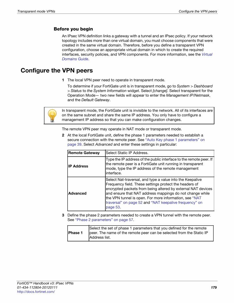
Transparent mode VPNs Configure the VPN peers
F
0
h
Before you begin An IPsec VPN definition links a gateway with a tunnel and an IPsec policy. If your network
topology includes more than one virtual domain, you must choose components that were
created in the same virtual domain. Therefore, before you define a transparent VPN
configuration, choose an appropriate virtual domain in which to create the required
interfaces, security policies, and VPN components. For more information, see the Virtual
Domains Guide.
Configure the VPN peers
1 The local VPN peer need to operate in transparent mode.
To determine if your FortiGate unit is in transparent mode, go to System > Dashboard
> Status to the System Information widget. Select [change]. Select transparent for the
Operation Mode— two new fields will appear to enter the Management IP/Netmask,
and the Default Gateway.
The remote VPN peer may operate in NAT mode or transparent mode.
2 At the local FortiGate unit, define the phase 1 parameters needed to establish a
secure connection with the remote peer. See “Auto Key phase 1 parameters” on
page 39. Select Advanced and enter these settings in particular:
3 Define the phase 2 parameters needed to create a VPN tunnel with the remote peer.
See “Phase 2 parameters” on page 57.
In transparent mode, the FortiGate unit is invisible to the network. All of its interfaces are
on the same subnet and share the same IP address. You only have to configure a
management IP address so that you can make configuration changes.
Remote Gateway Select Static IP Address.
IP Address
Type the IP address of the public interface to the remote peer. If
the remote peer is a FortiGate unit running in transparent
mode, type the IP address of the remote management
interface.
Advanced
Select Nat-traversal, and type a value into the Keepalive
Frequency field. These settings protect the headers of
encrypted packets from being altered by external NAT devices
and ensure that NAT address mappings do not change while
the VPN tunnel is open. For more information, see “NAT
traversal” on page 52 and “NAT keepalive frequency” on
page 53.
Phase 1
Select the set of phase 1 parameters that you defined for the remote
peer. The name of the remote peer can be selected from the Static IP
Address list.
ortiOS™ Handbook v3: IPsec VPNs
1-434-112804-20120111 179ttp://docs.fortinet.com/

Configure the VPN peers Transparent mode VPNs
4 Define the source and destination addresses of the IP packets that are to be
transported through the VPN tunnel. See “Defining policy addresses” on page 63.
Enter these settings in particular:
• For the originating address (source address), enter the IP address and netmask of
the private network behind the local peer network. for the management interface,
for example, 10.10.10.0/24. This address needs to be a range to allow traffic
from your network through the tunnel. Optionally select any for this address.
• For the remote address (destination address), enter the IP address and netmask of
the private network behind the remote peer (for example, 192.168.10.0/24). If
the remote peer is a FortiGate unit running in transparent mode, enter the IP
address of the remote management interface instead.
5 Define an IPsec security policy to permit communications between the source and
destination addresses. See “Defining VPN security policies” on page 64. Enter these
settings in particular:
6 Place the policy in the policy list above any other policies having similar source and
destination addresses.
7 Define another IPsec security policy to permit communications between the source
and destination addresses in the opposite direction. This security policy and the
previous one form a bi-directional policy pair. See “Defining VPN security policies” on
page 64. Enter these settings in particular:
Source Interface/ZoneSelect the local interface to the internal (private)
network.
Source Address Name Select the source address that you defined in Step 4.
Destination
Interface/Zone
Select the interface to the edge router. When you
configure the IPsec security policy on a remote peer that
operates in NAT mode, you select the public interface to
the external (public) network instead.
Destination Address
Name
Select the destination address that you defined in
Step 4.
Action IPSEC
VPN Tunnel
Select the name of the phase 2 tunnel configuration that
you created in Step 3.
Select Allow inbound to enable traffic from the remote
network to initiate the tunnel.
Select Allow outbound to enable traffic from the local
network to initiate the tunnel.
Source Interface/Zone
Select the interface to the edge router. When you
configure the IPsec security policy on a remote peer that
operates in NAT mode, you select the public interface to
the external (public) network instead.
Source Address NameSelect the destination address that you defined in
Step 4.
Destination
Interface/Zone
Select the local interface to the internal (private)
network.
IPsec VPNs for FortiOS 4.0 MR3
180 01-434-112804-20120111
http://docs.fortinet.com/
Transparent mode VPNs Configure the VPN peers
F
0
h
8 Repeat this procedure at the remote FortiGate unit to create bidirectional security
policies. Use the local interface and address information local to the remote FortiGate
unit.
For more information on transparent mode, see the System Administration Guide.
Destination Address
Name
Select the source address that you defined in Step 4.
Action IPSEC
VPN Tunnel
Select the name of the phase 2 tunnel configuration that
you created in Step 3.
Select Allow inbound to enable traffic from the remote
network to initiate the tunnel.
Select Allow outbound to enable traffic from the local
network to initiate the tunnel.
ortiOS™ Handbook v3: IPsec VPNs
1-434-112804-20120111 181ttp://docs.fortinet.com/

Configure the VPN peers Transparent mode VPNs
IPsec VPNs for FortiOS 4.0 MR3
182 01-434-112804-20120111
http://docs.fortinet.com/

F o r t i O S H a n d b o o k
F
0
h
Manual-key configurations This section explains how to manually define cryptographic keys to establish an IPsec
VPN, either policy-based or route-based.
For more information on web-based manual key configuration, see “Manual Key” on
page 35.
The following topics are included in this section:
• Configuration overview
• Specify the manual keys for creating a tunnel
Configuration overview
You manual define cryptographic keys where prior knowledge of the encryption and/or
authentication key is required (that is, one of the VPN peers requires a specific IPsec
encryption and/or authentication key). In this case, you do not specify IPsec phase 1 and
phase 2 parameters; you define manual keys by going to VPN > IPsec > Manual Key.
If one VPN peer uses specific authentication and encryption keys to establish a tunnel,
both VPN peers must be configured to use the same encryption and authentication
algorithms and keys.
It is essential that both VPN peers be configured with matching encryption and
authentication algorithms, matching authentication and encryption keys, and
complementary Security Parameter Index (SPI) settings.
You can define either the encryption or the authentication as NULL (disabled), but not
both.
Each SPI identifies a Security Association (SA). The value is placed in ESP datagrams to
link the datagrams to the SA. When an ESP datagram is received, the recipient refers to
the SPI to determine which SA applies to the datagram. An SPI must be specified
manually for each SA. Because an SA applies to communication in one direction only,
you must specify two SPIs per configuration (a local SPI and a remote SPI) to cover
bidirectional communications between two VPN peers.
It may not be safe or practical to define manual keys because network administrators
must be trusted to keep the keys confidential, and propagating changes to remote VPN
peers in a secure manner may be difficult.
If you are not familiar with the security policies, SAs, selectors, and SA databases for your
particular installation, do not attempt the following procedure without qualified
assistance.
ortiOS™ Handbook v3: IPsec VPNs
1-434-112804-20120111 183ttp://docs.fortinet.com/

Specify the manual keys for creating a tunnel Manual-key configurations
Specify the manual keys for creating a tunnel
Specify the manual keys for creating a tunnel as follows:
1 Go to VPN > IPsec > Manual Key and select Create New.
2 Include appropriate entries as follows:
Name Type a name for the VPN tunnel.
Local SPI
Type a hexadecimal number (up to 8 characters, 0-9, a-f) that
represents the SA that handles outbound traffic on the local
FortiGate unit. The valid range is from 0x100 to 0xffffffff.
This value must match the Remote SPI value in the manual key
configuration at the remote peer.
Remote SPI
Type a hexadecimal number (up to 8 characters, 0-9, a-f) that
represents the SA that handles inbound traffic on the local
FortiGate unit. The valid range is from 0x100 to 0xffffffff.
This value must match the Local SPI value in the manual key
configuration at the remote peer.
Remote
Gateway
Type the IP address of the public interface to the remote peer. The
address identifies the recipient of ESP datagrams.
Local Interface
Select the name of the physical, aggregate, or VLAN interface to
which the IPsec tunnel will be bound. The FortiGate unit obtains
the IP address of the interface from System > Network > Interface
settings. This is available in NAT mode only.
Encryption
Algorithm
Select one of the following symmetric-key encryption algorithms:
• DES — Digital Encryption Standard, a 64-bit block algorithm
that uses a 56-bit key.
• 3DES — Triple-DES, in which plain text is encrypted three
times by three keys.
• AES128 — A 128-bit block algorithm that uses a 128-bit key.
• AES192 — A 128-bit block algorithm that uses a 192-bit key.
• AES256 — A 128-bit block algorithm that uses a 256-bit key.
Encryption Key
If you selected:
• DES, type a 16-character hexadecimal number (0-9, a-f).
• 3DES, type a 48-character hexadecimal number (0-9, a-f)
separated into three segments of 16 characters.
• AES128, type a 32-character hexadecimal number (0-9, a-f)
separated into two segments of 16 characters.
• AES192, type a 48-character hexadecimal number (0-9, a-f)
separated into three segments of 16 characters.
• AES256, type a 64-character hexadecimal number (0-9, a-f)
separated into four segments of 16 characters.
Authentication
Algorithm
Select one of the following message digests:
• MD5 — Message Digest 5 algorithm, which produces a 128-bit
message digest.
• SHA1 — Secure Hash Algorithm 1, which produces a 160-bit
message digest.
IPsec VPNs for FortiOS 4.0 MR3
184 01-434-112804-20120111
http://docs.fortinet.com/
Manual-key configurations Specify the manual keys for creating a tunnel
F
0
h
3 Select OK.
Authentication
Key
If you selected:
• MD5, type a 32-character hexadecimal number (0-9, a-f)
separated into two segments of 16 characters.
• SHA1, type 40-character hexadecimal number (0-9, a-f)
separated into one segment of 16 characters and a second
segment of 24 characters.
IPsec Interface
Mode
Select to create a route-based VPN. A virtual IPsec interface is
created on the Local Interface that you selected. This option is
available only in NAT mode.
ortiOS™ Handbook v3: IPsec VPNs
1-434-112804-20120111 185ttp://docs.fortinet.com/

Specify the manual keys for creating a tunnel Manual-key configurations
IPsec VPNs for FortiOS 4.0 MR3
186 01-434-112804-20120111
http://docs.fortinet.com/

F o r t i O S H a n d b o o k
F
0
h
IPv6 IPsec VPNsThis chapter describes how to configure your FortiGate unit’s IPv6 IPsec VPN
functionality. To access IPv6 functionality through the web-based manager, go to System
Admin > Settings and enable IPv6 in the section, Display Options on GUI.
The following topics are included in this section:
• Overview of IPv6 IPsec support
• Configuring IPv6 IPsec VPNs
• Site-to-site IPv6 over IPv6 VPN example
• Site-to-site IPv4 over IPv6 VPN example
• Site-to-site IPv6 over IPv4 VPN example
Overview of IPv6 IPsec support
FortiOS supports route-based IPv6 IPsec, but not policy-based. This section describes
how IPv6 IPsec support differs from IPv4 IPsec support. FortiOS 4.0 MR3 is Pv6 Ready
Logo Program Phase 2 certified.
Where both the gateways and the protected networks use IPv6 addresses, sometimes
called IPv6 over IPv6, you can create either an auto-keyed or manually-keyed VPN. You
can combine IPv6 and IPv4 addressing in an auto-keyed VPN in the following ways:
Compared with IPv4 IPsec VPN functionality, there are some limitations:
• Except for IPv6 over IPv4, remote gateways with Dynamic DNS are not supported.
This is because FortiOS 3.0 does not support IPv6 DNS.
• You cannot use RSA certificates in which the common name (cn) is a domain name
that resolves to an IPv6 address. This is because FortiOS 3.0 does not support IPv6
DNS.
• DHCP over IPsec is not supported, because FortiOS 3.0 does not support IPv6 DHCP.
• Selectors cannot be firewall address names. Only IP address, address range and
subnet are supported.
• Redundant IPv6 tunnels are not supported.
Certificates
On a VPN with IPv6 phase 1 configuration, you can authenticate using VPN certificates in
which the common name (cn) is an IPv6 address. The cn-type keyword of the user peer command has an option, ipv6, to support this.
IPv4 over IPv6
The VPN gateways have IPv6 addresses.
The protected networks have IPv4 addresses. The phase 2
configurations at either end use IPv4 selectors.
IPv6 over IPv4
The VPN gateways have IPv4 addresses.
The protected networks use IPv6 addresses. The phase 2
configurations at either end use IPv6 selectors.
ortiOS™ Handbook v3: IPsec VPNs
1-434-112804-20120111 187ttp://docs.fortinet.com/
Configuring IPv6 IPsec VPNs IPv6 IPsec VPNs
Configuring IPv6 IPsec VPNs
Configuration of an IPv6 IPsec VPN follows the same sequence as for an IPv4 route-
based VPN: phase 1 settings, phase 2 settings, security policies and routing.
To access IPv6 functionality through the web-based manager, go to System Admin >
Settings and enable IPv6 in the section, Display Options on GUI.
Phase 1 configuration
In the web-based manager, you define the Phase 1 as IPv6 in the Advanced settings.
Enable the IPv6 Version check box. You can then enter an IPv6 address for the remote
gateway.
In the CLI, you define an IPsec phase 1 configuration as IPv6 by setting ip-version
to 6. Its default value is 4. Then, the local-gw and remote-gw keywords are hidden
and the corresponding local-gw6 and remote-gw6 keywords are available. The values
for local-gw6 and remote-gw6 must be IPv6 addresses. For example:
config vpn ipsec phase1-interfaceedit tunnel6set ip-version 6set remote-gw6 0:123:4567::1234set interface port3set proposal 3des-md5
end
Phase 2 configuration
To create an IPv6 IPsec phase 2 configuration in the web-based manager, you need to
define IPv6 selectors in the Advanced settings. Change the default “0.0.0.0/0” address
for Source address and Destination address to the IPv6 value “::/0”. If needed, enter
specific IPv6 addresses, address ranges or subnet addresses in these fields.
In the CLI, set src-addr-type and dst-addr-type to ip6, range6 or subnet6 to
specify IPv6 selectors. By default, zero selectors are entered, “::/0” for the subnet6
address type, for example. The simplest IPv6 phase 2 configuration looks like this:
config vpn ipsec phase2-interfaceedit tunnel6_p2set phase1name tunnel6set proposal 3des-md5set src-addr-type subnet6set dst-addr-type subnet6
end
Security policies
To complete the VPN configuration, you need a security policy in each direction to permit
traffic between the protected network’s port and the IPsec interface. You need IPv6
policies unless the VPN is IPv4 over IPv6.
Routing
Appropriate routing is needed for both the IPsec packets and the encapsulated traffic
within them. You need a route, which could be the default route, to the remote VPN
gateway via the appropriate interface. You also need a route to the remote protected
network via the IPsec interface.
IPsec VPNs for FortiOS 4.0 MR3
188 01-434-112804-20120111
http://docs.fortinet.com/

IPv6 IPsec VPNs Site-to-site IPv6 over IPv6 VPN example
F
0
h
To create a static route in the web-based manager, go to Router > Static > Static Route.
Select the drop-down arrow on the Create New button and select IPv6 Route. Enter the
information and select OK. In the CLI, use the router static6 command. For
example, where the remote network is fec0:0000:0000:0004::/64 and the IPsec interface
is toB:
config router static6edit 1set device port2set dst 0::/0
nextedit 2set device toBset dst fec0:0000:0000:0004::/64
nextend
If the VPN is IPV4 over IPv6, the route to the remote protected network is an IPv4 route. If
the VPN is IPv6 over IPv4, the route to the remote VPN gateway is an IPv4 route.
Site-to-site IPv6 over IPv6 VPN example
In this example, computers on IPv6-addressed private networks communicate securely
over public IPv6 infrastructure.
To access IPv6 functionality through the web-based manager, go to System Admin >
Settings and enable IPv6 in the section, Display Options on GUI.
Figure 30: Example IPv6-over-IPv6 VPN topology
Configure FortiGate A interfaces
Port 2 connects to the public network and port 3 connects to the local network.
config system interfaceedit port2config ipv6set ip6-address fec0::0001:209:0fff:fe83:25f2/64
endnext
FortiGate BPort 3
fec0:0000:0000:0000::/64 fec0:0000:0000:0004::/64
Port 2
fec0:0001:209:0fff:fe83:25f2
Port 3rt 333333FoFooFortttrtiGiGiGiGatatateee BBB
PPPPPoPo
Port 2
fec0:0001:209:0fff:fe83:25c7
FortiGate A
ortiOS™ Handbook v3: IPsec VPNs
1-434-112804-20120111 189ttp://docs.fortinet.com/
Site-to-site IPv6 over IPv6 VPN example IPv6 IPsec VPNs
edit port3config ipv6set ip6-address fec0::0000:209:0fff:fe83:25f3/64
endnext
end
Configure FortiGate A IPsec settings
The phase 1 configuration creates a virtual IPsec interface on port 2 and sets the remote
gateway to the public IP address FortiGate B. This configuration is the same as for an
IPv4 route-based VPN, except that ip-version is set to 6 and the remote-gw6
keyword is used to specify an IPv6 remote gateway address.
config vpn ipsec phase1-interfaceedit toBset ip-version 6set interface port2set remote-gw6 fec0:0000:0000:0003:209:0fff:fe83:25c7set dpd enableset psksecret maryhadalittlelambset proposal 3des-md5 3des-sha1
end
By default, phase 2 selectors are set to accept all subnet addresses for source and
destination. The default setting for src-addr-type and dst-addr-type is subnet.
The IPv6 equivalent is subnet6. The default subnet addresses are 0.0.0.0/0 for IPv4,
::/0 for IPv6.
config vpn ipsec phase2-interfaceedit toB2set phase1name toBset proposal 3des-md5 3des-sha1set pfs enableset replay enableset src-addr-type subnet6set dst-addr-type subnet6
end
Configure FortiGate A security policies
Security policies are required to allow traffic between port3 and the IPsec interface toB in
each direction. The address all6 must be defined using the firewall address6
command as ::/0.
config firewall policy6edit 1set srcintf port3set dstintf toBset srcaddr all6set dstaddr all6set action acceptset service ANYset schedule always
nextedit 2set srcintf toBset dstintf port3
IPsec VPNs for FortiOS 4.0 MR3
190 01-434-112804-20120111
http://docs.fortinet.com/

IPv6 IPsec VPNs Site-to-site IPv6 over IPv6 VPN example
F
0
h
set srcaddr all6set dstaddr all6set action acceptset service ANYset schedule always
end
Configure FortiGate A routing
This simple example requires just two static routes. Traffic to the protected network
behind FortiGate B is routed via the virtual IPsec interface toB. A default route sends all
IPv6 traffic out on port2.
config router static6edit 1set device port2set dst 0::/0
nextedit 2set device toBset dst fec0:0000:0000:0004::/64
end
Configure FortiGate B
The configuration of FortiGate B is very similar to that of FortiGate A. A virtual IPsec
interface toA is configured on port2 and its remote gateway is the public IP address of
FortiGate A. Security policies enable traffic to pass between the private network and the
IPsec interface. Routing ensures traffic for the private network behind FortiGate A goes
through the VPN and that all IPv6 packets are routed to the public network.
config system interfaceedit port2config ipv6set ip6-address fec0::0003:209:0fff:fe83:25c7/64
endnextedit port3config ipv6set ip6-address fec0::0004:209:0fff:fe83:2569/64
endend
config vpn ipsec phase1-interfaceedit toAset ip-version 6set interface port2set remote-gw6 fec0:0000:0000:0001:209:0fff:fe83:25f2set dpd enableset psksecret maryhadalittlelambset proposal 3des-md5 3des-sha1
endconfig vpn ipsec phase2-interfaceedit toA2set phase1name toAset proposal 3des-md5 3des-sha1set pfs enableset replay enable
ortiOS™ Handbook v3: IPsec VPNs
1-434-112804-20120111 191ttp://docs.fortinet.com/
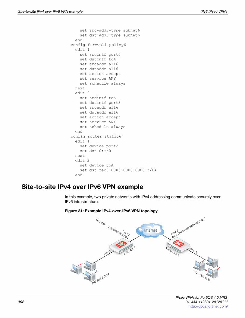
Site-to-site IPv4 over IPv6 VPN example IPv6 IPsec VPNs
set src-addr-type subnet6set dst-addr-type subnet6
endconfig firewall policy6edit 1set srcintf port3set dstintf toAset srcaddr all6set dstaddr all6set action acceptset service ANYset schedule always
nextedit 2set srcintf toAset dstintf port3set srcaddr all6set dstaddr all6set action acceptset service ANYset schedule always
endconfig router static6edit 1set device port2set dst 0::/0
nextedit 2set device toAset dst fec0:0000:0000:0000::/64
end
Site-to-site IPv4 over IPv6 VPN example
In this example, two private networks with IPv4 addressing communicate securely over
IPv6 infrastructure.
Figure 31: Example IPv4-over-IPv6 VPN topology
FortiGate BFortiGate A
192.168.2.0/24192.168.3.0/24
Port 2
fec0:0001:209:0fff:fe83:25f2
Port 3FoFoFoFoFoForttrtrtrtrtiGiGiGiGiGiG
atatatatatateeee e AA FoFooFortrttrtiGiGiGiGatatatateee BBB
PPPo
Port 2
fec0:0001:209:0fff:fe83:25c7
Port 3
IPsec VPNs for FortiOS 4.0 MR3
192 01-434-112804-20120111
http://docs.fortinet.com/
IPv6 IPsec VPNs Site-to-site IPv4 over IPv6 VPN example
F
0
h
Configure FortiGate A interfaces
Port 2 connects to the IPv6 public network and port 3 connects to the IPv4 LAN.
config system interfaceedit port2config ipv6set ip6-address fec0::0001:209:0fff:fe83:25f2/64
endnextedit port3set 192.168.2.1/24
end
Configure FortiGate A IPsec settings
The phase 1 configuration is the same as in the IPv6 over IPv6 example.
config vpn ipsec phase1-interfaceedit toBset ip-version 6set interface port2set remote-gw6 fec0:0000:0000:0003:209:0fff:fe83:25c7set dpd enableset psksecret maryhadalittlelambset proposal 3des-md5 3des-sha1
end
The phase 2 configuration is the same as you would use for an IPv4 VPN. By default,
phase 2 selectors are set to accept all subnet addresses for source and destination.
config vpn ipsec phase2-interfaceedit toB2set phase1name toBset proposal 3des-md5 3des-sha1set pfs enableset replay enable
end
Configure FortiGate A security policies
Security policies are required to allow traffic between port3 and the IPsec interface toB in
each direction. These are IPv4 security policies.
config firewall policyedit 1set srcintf port3set dstintf toBset srcaddr allset dstaddr allset action acceptset service ANYset schedule always
nextedit 2set srcintf toBset dstintf port3set srcaddr allset dstaddr all
ortiOS™ Handbook v3: IPsec VPNs
1-434-112804-20120111 193ttp://docs.fortinet.com/

Site-to-site IPv4 over IPv6 VPN example IPv6 IPsec VPNs
set action acceptset service ANYset schedule always
end
Configure FortiGate A routing
This simple example requires just two static routes. Traffic to the protected network
behind FortiGate B is routed via the virtual IPsec interface toB using an IPv4 static route.
A default route sends all IPv6 traffic, including the IPv6 IPsec packets, out on port2.
config router static6edit 1set device port2set dst 0::/0
nextedit 2set device toBset dst 192.168.3.0/24
end
Configure FortiGate B
The configuration of FortiGate B is very similar to that of FortiGate A. A virtual IPsec
interface toA is configured on port2 and its remote gateway is the public IP address of
FortiGate A. The IPsec phase 2 configuration has IPv4 selectors.
IPv4 security policies enable traffic to pass between the private network and the IPsec
interface. An IPv4 static route ensures traffic for the private network behind FortiGate A
goes through the VPN and an IPv6 static route ensures that all IPv6 packets are routed to
the public network.
config system interfaceedit port2config ipv6set ip6-address fec0::0003:fe83:25c7/64
endnextedit port3set 192.168.3.1/24
endconfig vpn ipsec phase1-interfaceedit toAset ip-version 6set interface port2set remote-gw6 fec0:0000:0000:0001:209:0fff:fe83:25f2set dpd enableset psksecret maryhadalittlelambset proposal 3des-md5 3des-sha1
endconfig vpn ipsec phase2-interfaceedit toA2set phase1name toAset proposal 3des-md5 3des-sha1set pfs enableset replay enable
end
IPsec VPNs for FortiOS 4.0 MR3
194 01-434-112804-20120111
http://docs.fortinet.com/

IPv6 IPsec VPNs Site-to-site IPv6 over IPv4 VPN example
F
0
h
config firewall policyedit 1set srcintf port3set dstintf toAset srcaddr allset dstaddr allset action acceptset service ANYset schedule always
nextedit 2set srcintf toAset dstintf port3set srcaddr allset dstaddr allset action acceptset service ANYset schedule always
endconfig router static6edit 1set device port2set dst 0::/0
nextedit 2set device toAset dst 192.168.2.0/24
end
Site-to-site IPv6 over IPv4 VPN example
In this example, IPv6-addressed private networks communicate securely over IPv4 public
infrastructure.
Figure 32: Example IPv6-over-IPv4 VPN topology
Configure FortiGate A interfaces
Port 2 connects to the IPv4 public network and port 3 connects to the IPv6 LAN.
FortiGate BFortiGate A
fec0:0000:0000:0000::/64 fec0:0000:0000:0004::/64
Port 2
10.0.0.1/24
Port 3FoFoFoFoFoFortrtrtrtrrt GiGGiGiGiGiGatatatatatateeee e AA
101
FoFooFortrtrrtiGiGiGiGatatatateee BBB
PPPPPPoPoP r
Port 210.0.1.1/24
Port 3
ortiOS™ Handbook v3: IPsec VPNs
1-434-112804-20120111 195ttp://docs.fortinet.com/
Site-to-site IPv6 over IPv4 VPN example IPv6 IPsec VPNs
config system interfaceedit port2set 10.0.0.1/24
nextedit port3config ipv6set ip6-address fec0::0001:209:0fff:fe83:25f3/64
end
Configure FortiGate A IPsec settings
The phase 1 configuration uses IPv4 addressing.
config vpn ipsec phase1-interfaceedit toBset interface port2set remote-gw 10.0.1.1set dpd enableset psksecret maryhadalittlelambset proposal 3des-md5 3des-sha1
end
The phase 2 configuration uses IPv6 selectors. By default, phase 2 selectors are set to
accept all subnet addresses for source and destination. The default setting for
src-addr-type and dst-addr-type is subnet. The IPv6 equivalent is subnet6. The
default subnet addresses are 0.0.0.0/0 for IPv4, ::/0 for IPv6.
config vpn ipsec phase2-interfaceedit toB2set phase1name toBset proposal 3des-md5 3des-sha1set pfs enableset replay enableset src-addr-type subnet6set dst-addr-type subnet6
end
Configure FortiGate A security policies
IPv6 security policies are required to allow traffic between port3 and the IPsec interface
toB in each direction. The address all6 must be defined using the
firewall address6 command as ::/0.
config firewall policy6edit 1set srcintf port3set dstintf toBset srcaddr all6set dstaddr all6set action acceptset service ANYset schedule always
nextedit 2set srcintf toBset dstintf port3set srcaddr all6set dstaddr all6
IPsec VPNs for FortiOS 4.0 MR3
196 01-434-112804-20120111
http://docs.fortinet.com/

IPv6 IPsec VPNs Site-to-site IPv6 over IPv4 VPN example
F
0
h
set action acceptset service ANYset schedule always
end
Configure FortiGate A routing
This simple example requires just two static routes. Traffic to the protected network
behind FortiGate B is routed via the virtual IPsec interface toB using an IPv6 static route.
A default route sends all IPv4 traffic, including the IPv4 IPsec packets, out on port2.
config router static6edit 1set device toBset dst fec0:0000:0000:0004::/64
endconfig router staticedit 1set device port2set dst 0.0.0.0/0set gateway 10.0.0.254
end
Configure FortiGate B
The configuration of FortiGate B is very similar to that of FortiGate A. A virtual IPsec
interface toA is configured on port2 and its remote gateway is the IPv4 public IP address
of FortiGate A. The IPsec phase 2 configuration has IPv6 selectors.
IPv6 security policies enable traffic to pass between the private network and the IPsec
interface. An IPv6 static route ensures traffic for the private network behind FortiGate A
goes through the VPN and an IPv4 static route ensures that all IPv4 packets are routed to
the public network.
config system interfaceedit port2set 10.0.1.1/24
nextedit port3config ipv6set ip6-address fec0::0004:209:0fff:fe83:2569/64
endconfig vpn ipsec phase1-interfaceedit toAset interface port2set remote-gw 10.0.0.1set dpd enableset psksecret maryhadalittlelambset proposal 3des-md5 3des-sha1
endconfig vpn ipsec phase2-interfaceedit toA2set phase1name toAset proposal 3des-md5 3des-sha1set pfs enableset replay enableset src-addr-type subnet6
ortiOS™ Handbook v3: IPsec VPNs
1-434-112804-20120111 197ttp://docs.fortinet.com/

Site-to-site IPv6 over IPv4 VPN example IPv6 IPsec VPNs
set dst-addr-type subnet6end
config firewall policy6edit 1set srcintf port3set dstintf toAset srcaddr all6set dstaddr all6set action acceptset service ANYset schedule always
nextedit 2set srcintf toAset dstintf port3set srcaddr all6set dstaddr all6set action acceptset service ANYset schedule always
endconfig router static6edit 1set device toAset dst fec0:0000:0000:0000::/64
endconfig router staticedit 1set device port2set gateway 10.0.1.254
end
IPsec VPNs for FortiOS 4.0 MR3
198 01-434-112804-20120111
http://docs.fortinet.com/
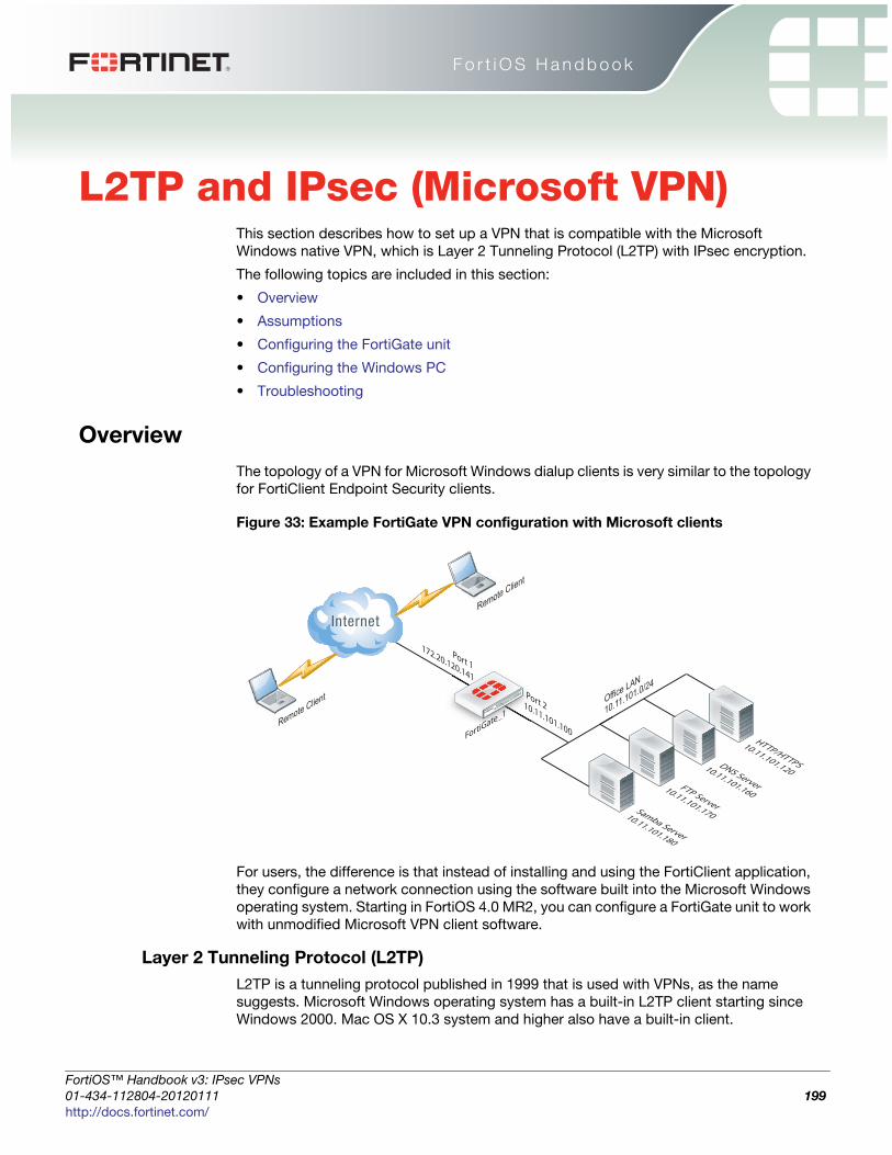
F o r t i O S H a n d b o o k
F
0
h
L2TP and IPsec (Microsoft VPN)This section describes how to set up a VPN that is compatible with the Microsoft
Windows native VPN, which is Layer 2 Tunneling Protocol (L2TP) with IPsec encryption.
The following topics are included in this section:
• Overview
• Assumptions
• Configuring the FortiGate unit
• Configuring the Windows PC
• Troubleshooting
Overview
The topology of a VPN for Microsoft Windows dialup clients is very similar to the topology
for FortiClient Endpoint Security clients.
Figure 33: Example FortiGate VPN configuration with Microsoft clients
For users, the difference is that instead of installing and using the FortiClient application,
they configure a network connection using the software built into the Microsoft Windows
operating system. Starting in FortiOS 4.0 MR2, you can configure a FortiGate unit to work
with unmodified Microsoft VPN client software.
Layer 2 Tunneling Protocol (L2TP)
L2TP is a tunneling protocol published in 1999 that is used with VPNs, as the name
suggests. Microsoft Windows operating system has a built-in L2TP client starting since
Windows 2000. Mac OS X 10.3 system and higher also have a built-in client.
FortiGate_1
GGGGGG tatatatatatatateeeeee_ee_11111111
Office LAN
10.11.101.0/24
Port 1
172.20.120.141
Port 2 10.11.101.100
Remote Client
Remote Client
HTTP/HTTPS
10.11.101.120DNS Server
10.11.101.160FTP Server
10.11.101.170Samba Server
10.11.101.180
ortiOS™ Handbook v3: IPsec VPNs
1-434-112804-20120111 199ttp://docs.fortinet.com/
Assumptions L2TP and IPsec (Microsoft VPN)
L2TP provides no encryption and used UDP port 1701. IPsec is used to secure L2TP
packets. The initiator of the L2TP tunnel is called the L2TP Access Concentrator (LAC).
Assumptions
The following assumptions have been made for this example:
• L2TP protocol traffic is allowed through network firewalls (TCP and UDP port 1701)
• User has Microsoft Windows 2000 or higher — a Windows version that supports L2TP
Configuring the FortiGate unit
To configure the FortiGate unit, you need to:
• configure LT2P users and firewall user group;
• configure the L2TP VPN, including the IP address range it assigns to clients;
• configure an IPsec VPN with encryption and authentication settings that match the
Microsoft VPN client;
• configure security policies.
Configuring LT2P users and firewall user group
Remote users must be authenticated before they can request services and/or access
network resources through the VPN. The authentication process can use a password
defined on the FortiGate unit or an established external authentication mechanism such
as RADIUS or LDAP.
Creating user accountsYou need to create user accounts and then add these users to a firewall user group to be
used for L2TP authentication. The Microsoft VPN client can automatically send the user’s
Window network logon credentials. You might want to use these for their L2TP user name
and password.
To create a user account - web-based manager
1 Go to User > User > User and select Create New.
2 Enter the User Name.
3 Do one of the following:
• Select Password and enter the user’s assigned password.
• Select LDAP, RADIUS, or TACACS+ and select the authentication server from the
list. The authentication server must be already configured on the FortiGate unit.
4 Select OK.
L2TP and IPSec is supported for native Windows XP, Windows Vista and Mac OSX native
VPN clients. However, in Mac OSX (OSX 10.6.3, including patch releases) the L2TP
feature does not work properly on the Mac OS side.
IPsec VPNs for FortiOS 4.0 MR3
200 01-434-112804-20120111
http://docs.fortinet.com/
L2TP and IPsec (Microsoft VPN) Configuring the FortiGate unit
F
0
h
To create a user account - CLI
To create a user account called user1 with the password 123_user, you would enter:
config user localedit user1set type passwordset passwd "123_user"set status enable
end
Creating a user groupWhen clients connect using the L2TP-over-IPsec VPN, the FortiGate unit checks their
credentials against the user group you specify for L2TP authentication. You need to
create a firewall user group to use for this purpose.
To create a user group - web-based manager
1 Go to User > User Group > User Group, select Create New, and enter the following
information:
2 Select OK.
To create a user group - CLI
To create the user group L2TP_group and add members User_1, User_2, and User_3,
you would enter:
config user groupedit L2TP_groupset group-type firewallset member User_1 User_2 User_3
end
Configuring L2TP
You can only configure L2TP settings in the CLI. As well as enabling L2TP, you set the
range of IP address values that are assigned to L2TP clients and specify the user group
that can access the VPN. For example, to allow access to users in the L2TP_group and
assign them addresses in the range 192.168.0.50 to 192.168.0.59, you would enter
config vpn l2tpset sip 192.168.0.50set eip 192.168.0.59set status enableset usrgrp "L2TP_group"
end
Name Type or edit the user group name (for example, L2TP_group).
Type Select Firewall.
Available
Users/Groups
The list of Local users, RADIUS servers, LDAP servers, TACACS+
servers, or PKI users that can be added to the user group. To add a
member to this list, select the name and then select the right arrow
button.
Members
The list of Local users, RADIUS servers, LDAP servers, TACACS+
servers, or PKI users that belong to the user group. To remove a
member, select the name and then select the left arrow button.
ortiOS™ Handbook v3: IPsec VPNs
1-434-112804-20120111 201ttp://docs.fortinet.com/

Configuring the FortiGate unit L2TP and IPsec (Microsoft VPN)
One of the security policies for the L2TP over IPsec VPN uses the client address range,
so you need also need to create a firewall address for that range. For example,
config firewall addressedit L2TPclientsset type iprangeset end-ip 192.168.6.88set start-ip 192.168.6.85
end
Alternatively, you could define this range in the web-based manager.
Configuring IPsec
The Microsoft VPN client uses IPsec for encryption. The configuration needed on the
FortiGate unit is the same as for any other IPsec VPN with the following exceptions.
• Transport mode is used instead of tunnel mode.
• The encryption and authentication proposals must be compatible with the Microsoft
client.
L2TP over IPsec is supported on the FortiGate unit using policy-based, not route-based
configurations.
Configuring phase 1 - web-based manager
1 Go to VPN > IPsec > Auto Key (IKE) and select Create Phase 1.
2 Enter the following information and then select OK.
Name Enter a name for this VPN, dialup_p1 for example.
Remote Gateway Dialup User
Local InterfaceSelect the network interface that connects to the Internet.
For example, port1.
Mode Main (ID protection)
Authentication
Method
Preshared Key
Pre-shared KeyEnter the preshared key. This key must also be entered in
the Microsoft VPN client.
Advanced Select Advanced to enter the following information.
Enable IPsec Interface
Mode
This must not be selected.
P1 ProposalEnter the following Encryption/Authentication pairs:
AES256-MD5, 3DES-SHA1, AES192-SHA1
DH Group 2
NAT Traversal Enable
Dead Peer Detection Enable
IPsec VPNs for FortiOS 4.0 MR3
202 01-434-112804-20120111
http://docs.fortinet.com/
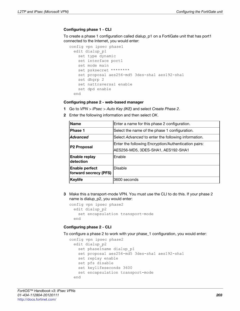
L2TP and IPsec (Microsoft VPN) Configuring the FortiGate unit
F
0
h
Configuring phase 1 - CLI
To create a phase 1 configuration called dialup_p1 on a FortiGate unit that has port1
connected to the Internet, you would enter:
config vpn ipsec phase1edit dialup_p1set type dynamicset interface port1set mode mainset psksecret ********set proposal aes256-md5 3des-sha1 aes192-sha1set dhgrp 2set nattraversal enableset dpd enable
end
Configuring phase 2 - web-based manager
1 Go to VPN > IPsec > Auto Key (IKE) and select Create Phase 2.
2 Enter the following information and then select OK.
3 Make this a transport-mode VPN. You must use the CLI to do this. If your phase 2
name is dialup_p2, you would enter:
config vpn ipsec phase2edit dialup_p2set encapsulation transport-mode
end
Configuring phase 2 - CLI
To configure a phase 2 to work with your phase_1 configuration, you would enter:
config vpn ipsec phase2edit dialup_p2set phase1name dialup_p1set proposal aes256-md5 3des-sha1 aes192-sha1set replay enableset pfs disableset keylifeseconds 3600set encapsulation transport-mode
end
Name Enter a name for this phase 2 configuration.
Phase 1 Select the name of the phase 1 configuration.
Advanced Select Advanced to enter the following information.
P2 ProposalEnter the following Encryption/Authentication pairs:
AES256-MD5, 3DES-SHA1, AES192-SHA1
Enable replay
detection
Enable
Enable perfect
forward secrecy (PFS)
Disable
Keylife 3600 seconds
ortiOS™ Handbook v3: IPsec VPNs
1-434-112804-20120111 203ttp://docs.fortinet.com/
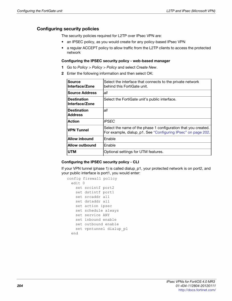
Configuring the FortiGate unit L2TP and IPsec (Microsoft VPN)
Configuring security policies
The security policies required for L2TP over IPsec VPN are:
• an IPSEC policy, as you would create for any policy-based IPsec VPN
• a regular ACCEPT policy to allow traffic from the L2TP clients to access the protected
network
Configuring the IPSEC security policy - web-based manager
1 Go to Policy > Policy > Policy and select Create New.
2 Enter the following information and then select OK:
Configuring the IPSEC security policy - CLI
If your VPN tunnel (phase 1) is called dialup_p1, your protected network is on port2, and
your public interface is port1, you would enter:
config firewall policyedit 0set srcintf port2set dstintf port1set srcaddr allset dstaddr allset action ipsecset schedule alwaysset service ANYset inbound enableset outbound enableset vpntunnel dialup_p1
end
Source
Interface/Zone
Select the interface that connects to the private network
behind this FortiGate unit.
Source Address all
Destination
Interface/Zone
Select the FortiGate unit’s public interface.
Destination
Address
all
Action IPSEC
VPN TunnelSelect the name of the phase 1 configuration that you created.
For example, dialup_p1. See “Configuring IPsec” on page 202.
Allow inbound Enable
Allow outbound Enable
UTM Optional settings for UTM features.
IPsec VPNs for FortiOS 4.0 MR3
204 01-434-112804-20120111
http://docs.fortinet.com/

L2TP and IPsec (Microsoft VPN) Configuring the Windows PC
F
0
h
Configuring the ACCEPT security policy - web-based manager
1 Go to Policy > Policy > Policy and select Create New.
2 Enter the following information and then select OK:
Configuring the ACCEPT security policy - CLI
If your public interface is port1, your protected network is on port2, and L2TPclients is
the address range that L2TP clients use, you would enter:
config firewall policyedit 0
set srcintf port1set dstintf port2set srcaddr L2TPclientsset dstaddr allset action acceptset schedule alwaysset service ANY
end
Configuring the Windows PC
Configuration of the Windows PC for a VPN connection to the FortiGate unit consists of
the following:
• In Network Connections, configure a Virtual Private Network connection to the
FortiGate unit.
• Ensure that the IPSEC service is running.
• Ensure that IPsec has not been disabled for the VPN client. It may have been disabled
to make the Microsoft VPN compatible with an earlier version of FortiOS.
The instructions in this section are based on Windows XP SP3. Other versions of
Windows may vary slightly.
To configure the network connection
1 Open Network Connections.
This is available through the Control Panel.
2 Double-click New Connection Wizard and Select Next.
3 Select Connect to the network at my workplace.
4 Select Next.
Source
Interface/Zone
Select the FortiGate unit’s public interface.
Source AddressSelect the firewall address that you defined for the L2TP
clients.
Destination
Interface/Zone
Select the interface that connects to the private network
behind this FortiGate unit.
Destination
Address
all
Action ACCEPT
UTM Optionally, select UTM feature profiles.
ortiOS™ Handbook v3: IPsec VPNs
1-434-112804-20120111 205ttp://docs.fortinet.com/

Troubleshooting L2TP and IPsec (Microsoft VPN)
5 Select Virtual Private Network connection and then select Next.
6 In the Company Name field, enter a name for the connection and then select Next.
7 Select Do not dial the initial connection and then select Next.
8 Enter the public IP address or FQDN of the FortiGate unit and then select Next.
9 Optionally, select Add a shortcut to this connection to my desktop.
10 Select Finish.
The Connect dialog opens on the desktop.
11 Select Properties and then select the Security tab.
12 Select IPSec Settings.
13 Select Use pre-shared key for authentication, enter the preshared key that you
configured for your VPN, and select OK.
14 Select OK.
To check that the IPSEC service is running
1 Open Administrative Tools.
This is available through the Control Panel.
2 Double-click Services.
3 Look for IPSEC Services. Confirm that the Startup Type is Automatic and Status is set
to Started. If needed, double-click IPSEC Services to change these settings.
To check that IPsec has not been disabled
1 Select Start > Run.
2 Enter regedit and select OK.
3 Find the Registry key
HKEY_LOCAL_MACHINE\SYSTEM\CurrentControlSet\Services\RasMan\Parameters
4 If there is a ProhibitIPSec value, it must be set to 0.
Troubleshooting
This section describes some checks and tools you can use to resolve issues with L2TP-
over-IPsec VPNs.
This section includes:
• Quick checks
• Mac OS X and L2TP
• Setting up logging
• Understanding the log messages
• Using the FortiGate unit debug commands
IPsec VPNs for FortiOS 4.0 MR3
206 01-434-112804-20120111
http://docs.fortinet.com/
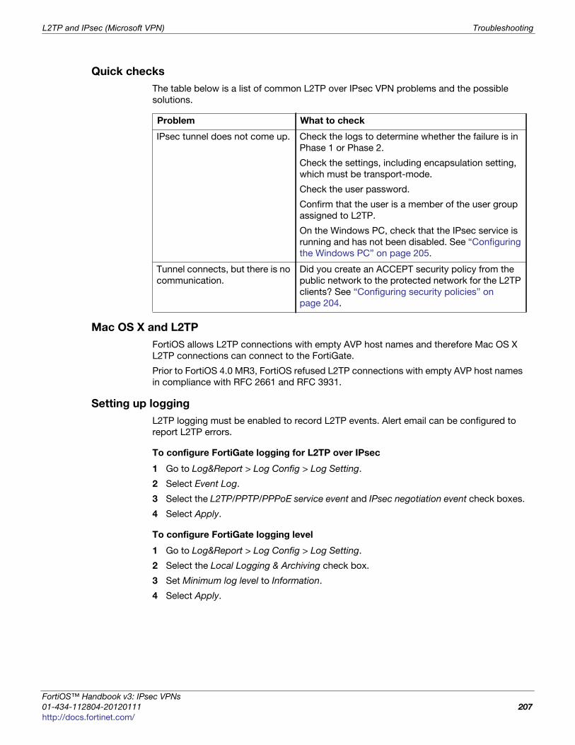
L2TP and IPsec (Microsoft VPN) Troubleshooting
F
0
h
Quick checks
The table below is a list of common L2TP over IPsec VPN problems and the possible
solutions.
Mac OS X and L2TP
FortiOS allows L2TP connections with empty AVP host names and therefore Mac OS X
L2TP connections can connect to the FortiGate.
Prior to FortiOS 4.0 MR3, FortiOS refused L2TP connections with empty AVP host names
in compliance with RFC 2661 and RFC 3931.
Setting up logging
L2TP logging must be enabled to record L2TP events. Alert email can be configured to
report L2TP errors.
To configure FortiGate logging for L2TP over IPsec
1 Go to Log&Report > Log Config > Log Setting.
2 Select Event Log.
3 Select the L2TP/PPTP/PPPoE service event and IPsec negotiation event check boxes.
4 Select Apply.
To configure FortiGate logging level
1 Go to Log&Report > Log Config > Log Setting.
2 Select the Local Logging & Archiving check box.
3 Set Minimum log level to Information.
4 Select Apply.
Problem What to check
IPsec tunnel does not come up. Check the logs to determine whether the failure is in
Phase 1 or Phase 2.
Check the settings, including encapsulation setting,
which must be transport-mode.
Check the user password.
Confirm that the user is a member of the user group
assigned to L2TP.
On the Windows PC, check that the IPsec service is
running and has not been disabled. See “Configuring
the Windows PC” on page 205.
Tunnel connects, but there is no
communication.
Did you create an ACCEPT security policy from the
public network to the protected network for the L2TP
clients? See “Configuring security policies” on
page 204.
ortiOS™ Handbook v3: IPsec VPNs
1-434-112804-20120111 207ttp://docs.fortinet.com/
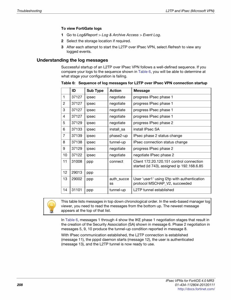
Troubleshooting L2TP and IPsec (Microsoft VPN)
To view FortiGate logs
1 Go to Log&Report > Log & Archive Access > Event Log.
2 Select the storage location if required.
3 After each attempt to start the L2TP over IPsec VPN, select Refresh to view any
logged events.
Understanding the log messages
Successful startup of an L2TP over IPsec VPN follows a well-defined sequence. If you
compare your logs to the sequence shown in Table 6, you will be able to determine at
what stage your configuration is failing.
In Table 6, messages 1 through 4 show the IKE phase 1 negotiation stages that result in
the creation of the Security Association (SA) shown in message 6. Phase 2 negotiation in
messages 5, 9, 10 produce the tunnel-up condition reported in message 8.
With IPsec communication established, the L2TP connection is established
(message 11), the pppd daemon starts (message 12), the user is authenticated
(message 13), and the L2TP tunnel is now ready to use.
Table 6: Sequence of log messages for L2TP over IPsec VPN connection startup
ID Sub Type Action Message
1 37127 ipsec negotiate progress IPsec phase 1
2 37127 ipsec negotiate progress IPsec phase 1
3 37127 ipsec negotiate progress IPsec phase 1
4 37127 ipsec negotiate progress IPsec phase 1
5 37129 ipsec negotiate progress IPsec phase 2
6 37133 ipsec install_sa install IPsec SA
7 37139 ipsec phase2-up IPsec phase 2 status change
8 37138 ipsec tunnel-up IPsec connection status change
9 37129 ipsec negotiate progress IPsec phase 2
10 37122 ipsec negotiate negotiate IPsec phase 2
11 31008 ppp connect Client 172.20.120.151 control connection
started (id 743), assigned ip 192.168.6.85
12 29013 ppp
13 29002 ppp auth_succe
ss
User 'user1' using l2tp with authentication
protocol MSCHAP_V2, succeeded
14 31101 ppp tunnel-up L2TP tunnel established
This table lists messages in top down chronological order. In the web-based manager log
viewer, you need to read the messages from the bottom up. The newest message
appears at the top of that list.
IPsec VPNs for FortiOS 4.0 MR3
208 01-434-112804-20120111
http://docs.fortinet.com/

L2TP and IPsec (Microsoft VPN) Troubleshooting
F
0
h
Using the FortiGate unit debug commands
To view debug output for IKE and L2TP
1 Start an SSH or Telnet session to your FortiGate unit.
2 Enter the following CLI commands
diagnose debug application ike -1diagnose debug application l2tp -1diagnose debug enable
3 Attempt to use the VPN and note the debug output in the SSH or Telnet session.
4 Enter the following command to reset debug settings to default:
diagnose debug reset
To use the packet sniffer
1 Start an SSH or Telnet session to your FortiGate unit.
2 Enter the following CLI command
diagnose sniffer packet any icmp 4
3 Attempt to use the VPN and note the debug output.
4 Enter Ctrl-C to end sniffer operation.
Typical L2TP over IPsec session startup log entries - raw format2010-01-11 16:39:58 log_id=0101037127 type=event subtype=ipsec pri=notice
vd="root" msg="progress IPsec phase 1" action="negotiate" rem_ip=172.20.120.151
loc_ip=172.20.120.141 rem_port=500 loc_port=500 out_intf="port1"
cookies="5f6da1c0e4bbf680/d6a1009eb1dde780" user="N/A" group="N/A"
xauth_user="N/A" xauth_group="N/A" vpn_tunnel="dialup_p1" status=success
init=remote mode=main dir=outbound stage=1 role=responder result=OK
2010-01-11 16:39:58 log_id=0101037127 type=event subtype=ipsec pri=notice
vd="root" msg="progress IPsec phase 1" action="negotiate" rem_ip=172.20.120.151
loc_ip=172.20.120.141 rem_port=500 loc_port=500 out_intf="port1"
cookies="5f6da1c0e4bbf680/d6a1009eb1dde780" user="N/A" group="N/A"
xauth_user="N/A" xauth_group="N/A" vpn_tunnel="dialup_p1" status=success
init=remote mode=main dir=outbound stage=2 role=responder result=OK
2010-01-11 16:39:58 log_id=0101037127 type=event subtype=ipsec pri=notice
vd="root" msg="progress IPsec phase 1" action="negotiate" rem_ip=172.20.120.151
loc_ip=172.20.120.141 rem_port=500 loc_port=500 out_intf="port1"
cookies="5f6da1c0e4bbf680/d6a1009eb1dde780" user="N/A" group="N/A"
xauth_user="N/A" xauth_group="N/A" vpn_tunnel="dialup_p1" status=success
init=remote mode=main dir=inbound stage=3 role=responder result=DONE
2010-01-11 16:39:58 log_id=0101037127 type=event subtype=ipsec pri=notice
vd="root" msg="progress IPsec phase 1" action="negotiate" rem_ip=172.20.120.151
loc_ip=172.20.120.141 rem_port=500 loc_port=500 out_intf="port1"
cookies="5f6da1c0e4bbf680/d6a1009eb1dde780" user="N/A" group="N/A"
xauth_user="N/A" xauth_group="N/A" vpn_tunnel="dialup_p1_0" status=success
init=remote mode=main dir=outbound stage=3 role=responder result=DONE
ortiOS™ Handbook v3: IPsec VPNs
1-434-112804-20120111 209ttp://docs.fortinet.com/

Troubleshooting L2TP and IPsec (Microsoft VPN)
2010-01-11 16:39:58 log_id=0101037129 type=event subtype=ipsec pri=notice
vd="root" msg="progress IPsec phase 2" action="negotiate" rem_ip=172.20.120.151
loc_ip=172.20.120.141 rem_port=500 loc_port=500 out_intf="port1"
cookies="5f6da1c0e4bbf680/d6a1009eb1dde780" user="N/A" group="N/A"
xauth_user="N/A" xauth_group="N/A" vpn_tunnel="dialup_p1_0" status=success
init=remote mode=quick dir=outbound stage=1 role=responder result=OK
2010-01-11 16:39:58 log_id=0101037133 type=event subtype=ipsec pri=notice
vd="root" msg="install IPsec SA" action="install_sa" rem_ip=172.20.120.151
loc_ip=172.20.120.141 rem_port=500 loc_port=500 out_intf="port1"
cookies="5f6da1c0e4bbf680/d6a1009eb1dde780" user="N/A" group="N/A"
xauth_user="N/A" xauth_group="N/A" vpn_tunnel="dialup_p1_0" role=responder
in_spi=61100fe2 out_spi=bd70fca1
2010-01-11 16:39:58 log_id=0101037139 type=event subtype=ipsec pri=notice
vd="root" msg="IPsec phase 2 status change" action="phase2-up"
rem_ip=172.20.120.151 loc_ip=172.20.120.141 rem_port=500 loc_port=500
out_intf="port1" cookies="5f6da1c0e4bbf680/d6a1009eb1dde780" user="N/A"
group="N/A" xauth_user="N/A" xauth_group="N/A" vpn_tunnel="dialup_p1_0"
phase2_name=dialup_p2
2010-01-11 16:39:58 log_id=0101037138 type=event subtype=ipsec pri=notice
vd="root" msg="IPsec connection status change" action="tunnel-up"
rem_ip=172.20.120.151 loc_ip=172.20.120.141 rem_port=500 loc_port=500
out_intf="port1" cookies="5f6da1c0e4bbf680/d6a1009eb1dde780" user="N/A"
group="N/A" xauth_user="N/A" xauth_group="N/A" vpn_tunnel="dialup_p1_0"
tunnel_ip=172.20.120.151 tunnel_id=1552003005 tunnel_type=ipsec duration=0 sent=0
rcvd=0 next_stat=0 tunnel=dialup_p1_0
2010-01-11 16:39:58 log_id=0101037129 type=event subtype=ipsec pri=notice
vd="root" msg="progress IPsec phase 2" action="negotiate" rem_ip=172.20.120.151
loc_ip=172.20.120.141 rem_port=500 loc_port=500 out_intf="port1"
cookies="5f6da1c0e4bbf680/d6a1009eb1dde780" user="N/A" group="N/A"
xauth_user="N/A" xauth_group="N/A" vpn_tunnel="dialup_p1_0" status=success
init=remote mode=quick dir=inbound stage=2 role=responder result=DONE
2010-01-11 16:39:58 log_id=0101037122 type=event subtype=ipsec pri=notice
vd="root" msg="negotiate IPsec phase 2" action="negotiate" rem_ip=172.20.120.151
loc_ip=172.20.120.141 rem_port=500 loc_port=500 out_intf="port1"
cookies="5f6da1c0e4bbf680/d6a1009eb1dde780" user="N/A" group="N/A"
xauth_user="N/A" xauth_group="N/A" vpn_tunnel="dialup_p1_0" status=success
role=responder esp_transform=ESP_3DES esp_auth=HMAC_SHA1
2010-01-11 16:39:58 log_id=0103031008 type=event subtype=ppp vd=root
pri=information action=connect status=success msg="Client 172.20.120.151 control
connection started (id 805), assigned ip 192.168.6.85"
2010-01-11 16:39:58 log_id=0103029013 type=event subtype=ppp vd=root pri=notice
pppd is started
2010-01-11 16:39:58 log_id=0103029002 type=event subtype=ppp vd=root pri=notice
user="user1" local=172.20.120.141 remote=172.20.120.151 assigned=192.168.6.85
action=auth_success msg="User 'user1' using l2tp with authentication protocol
MSCHAP_V2, succeeded"
2010-01-11 16:39:58 log_id=0103031101 type=event subtype=ppp vd=root
pri=information action=tunnel-up tunnel_id=1645784497 tunnel_type=l2tp
remote_ip=172.20.120.151 tunnel_ip=192.168.6.85 user="user1" group="L2TPusers"
msg="L2TP tunnel established"
IPsec VPNs for FortiOS 4.0 MR3
210 01-434-112804-20120111
http://docs.fortinet.com/
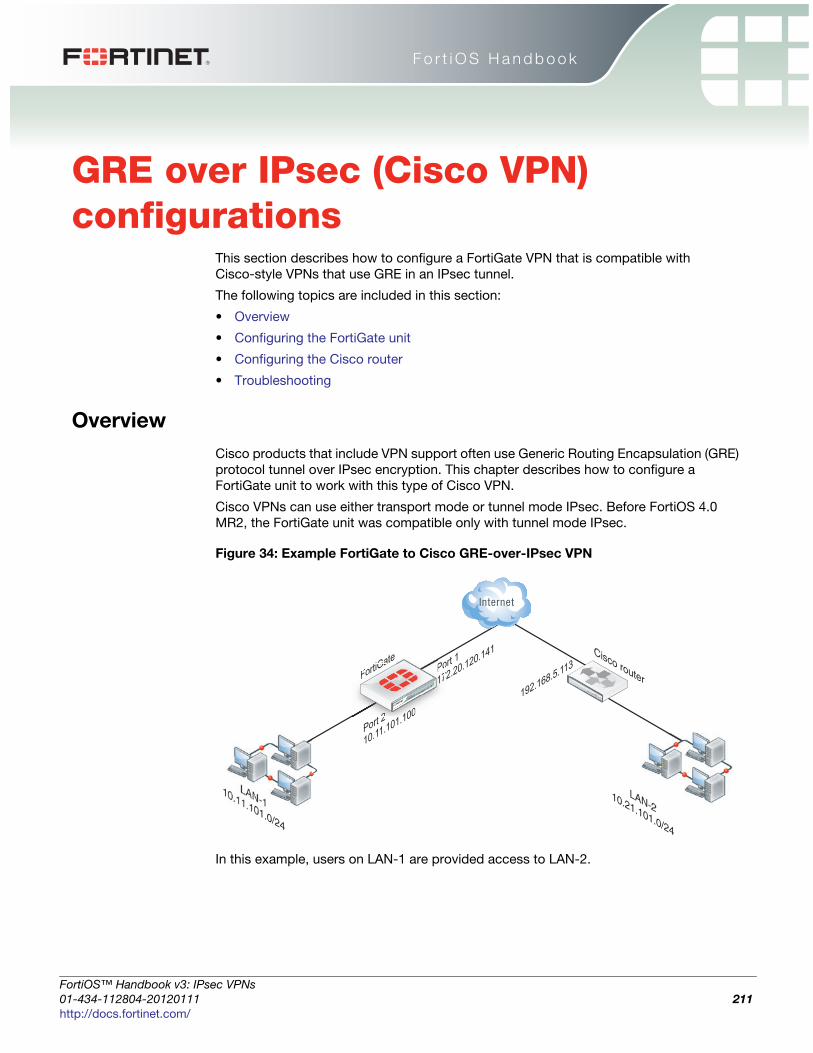
F o r t i O S H a n d b o o k
F
0
h
GRE over IPsec (Cisco VPN) configurations
This section describes how to configure a FortiGate VPN that is compatible with
Cisco-style VPNs that use GRE in an IPsec tunnel.
The following topics are included in this section:
• Overview
• Configuring the FortiGate unit
• Configuring the Cisco router
• Troubleshooting
Overview
Cisco products that include VPN support often use Generic Routing Encapsulation (GRE)
protocol tunnel over IPsec encryption. This chapter describes how to configure a
FortiGate unit to work with this type of Cisco VPN.
Cisco VPNs can use either transport mode or tunnel mode IPsec. Before FortiOS 4.0
MR2, the FortiGate unit was compatible only with tunnel mode IPsec.
Figure 34: Example FortiGate to Cisco GRE-over-IPsec VPN
In this example, users on LAN-1 are provided access to LAN-2.
Cisco routerFortiGate
LAN-110.11.101.0/24
LAN-210.21.101.0/24
Port 2
10.11.101.100
Port 1
172.20.120.141
192.168.5.113FortiG
a
t 222222 101000
Po17171
ortiOS™ Handbook v3: IPsec VPNs
1-434-112804-20120111 211ttp://docs.fortinet.com/
Configuring the FortiGate unit GRE over IPsec (Cisco VPN) configurations
Configuring the FortiGate unit
There are several steps to the GRE-over-IPsec configuration:
• Enable overlapping subnets. This is needed because the IPsec and GRE tunnels will
use the same addresses.
• Configure a route-based IPsec VPN on the external interface.
• Configure a GRE tunnel on the virtual IPsec interface. Set its local gateway and
remote gateway addresses to match the local and remote gateways of the IPsec
tunnel.
• Configure security policies to allow traffic to pass in both directions between the GRE
virtual interface and the IPsec virtual interface.
• Configure security policies to allow traffic to pass in both directions between the
protected network interface and the GRE virtual interface.
• Configure a static route to direct traffic destined for the network behind the Cisco
router into the GRE-over-IPsec tunnel.
Enabling overlapping subnets
By default, each FortiGate unit network interface must be on a separate network. The
configuration described in this chapter assigns an IPsec tunnel end point and the
external interface to the same network. Enable subnet overlap as follows:
config system settingsset allow-subnet-overlap enable
end
Configuring the IPsec VPN
A route-based VPN is required. It must use encryption and authentication algorithms
compatible with the Cisco equipment to which it connects. In this chapter, preshared key
authentication is shown.
To configure the IPsec VPN - web-based manager
1 Define the phase 1 configuration needed to establish a secure connection with the
remote Cisco device. Enter these settings in particular:
Name
Enter a name to identify the VPN tunnel, tocisco for
example. This is the name of the virtual IPsec interface. It
appears in phase 2 configurations, security policies and
the VPN monitor.
Remote Gateway Select Static IP Address.
IP AddressEnter the IP address of the Cisco device public interface.
For example, 192.168.5.113
Local InterfaceSelect the FortiGate unit’s public interface. For example,
172.20.120.141
Mode Select Main (ID Protection).
Authentication Method Preshared Key
Pre-shared KeyEnter the preshared key. It must match the preshared key
on the Cisco device.
Advanced Select the Advanced button to see the following settings.
IPsec VPNs for FortiOS 4.0 MR3
212 01-434-112804-20120111
http://docs.fortinet.com/

GRE over IPsec (Cisco VPN) configurations Configuring the FortiGate unit
F
0
h
For more information about these settings, see “Auto Key phase 1 parameters” on
page 39.
2 Define the phase 2 parameters needed to create a VPN tunnel with the remote peer.
For compatibility with the Cisco router, Quick Mode Selectors must be entered, which
includes specifying protocol 47, the GRE protocol. Enter these settings in particular:
For more information about these settings, see “Phase 2 parameters” on page 57.
3 If the Cisco device is configured to use transport mode IPsec, you need to use
transport mode on the FortiGate VPN. You can configure this only in the CLI. In your
phase 2 configuration, set encapsulation to transport-mode (default is
tunnel-mode) as follows:
config vpn phase2-interfaceedit to_cisco_p2set encapsulation transport-mode
end
To configure the IPsec VPN - CLI
config vpn ipsec phase1-interfaceedit tociscoset interface port1set proposal 3des-sha1 aes128-sha1set remote-gw 192.168.5.113set psksecret xxxxxxxxxxxxxxxx
endconfig vpn ipsec phase2-interfaceedit tocisco_p2set phase1name "tocisco"set proposal 3des-md5set encapsulation tunnel-mode // if tunnel mode
Enable IPsec Interface
Mode
Enable.
P1 Proposal
3DES-MD5
At least one proposal must match the settings on the
Cisco unit.
Name Enter a name to identify this phase 2 configuration.
Phase 1 Select the name of the phase 1 configuration that you defined in Step 1.
Advanced Select Advanced to view the following fields.
P2 Proposal3DES-MD5At least one proposal must match the settings on the Cisco unit.
Quick Mode Selector
Source AddressEnter the GRE local tunnel end IP address. For example 172.20.120.141
Source Port 0
Destination
Address
Enter the GRE remote tunnel end IP address. For example 192.168.5.113
Destination Port 0
Protocol 47
ortiOS™ Handbook v3: IPsec VPNs
1-434-112804-20120111 213ttp://docs.fortinet.com/
Configuring the FortiGate unit GRE over IPsec (Cisco VPN) configurations
set encapsulation transport-mode // if transport modeset protocol 47set src-addr-type ipset dst-start-ip 192.168.5.113set src-start-ip 172.20.120.141
end
Adding IPsec tunnel end addressesThe Cisco configuration requires an address for its end of the IPsec tunnel. The
addresses are set to match the GRE gateway addresses. Use the CLI to set the
addresses, like this:
config system interfaceedit tociscoset ip 172.20.120.141 255.255.255.255set remote-ip 192.168.5.113
end
Configuring the GRE tunnel
The GRE tunnel runs between the virtual IPsec public interface on the FortiGate unit and
the Cisco router. You must use the CLI to configure a GRE tunnel. In the example, you
would enter:
config system gre-tunneledit gre1set interface tociscoset local-gw 172.20.120.141set remote-gw 192.168.5.113
end
interface is the virtual IPsec interface, local-gw is the FortiGate unit public IP
address, and remote-gw is the remote Cisco device public IP address
Adding GRE tunnel end addressesYou will also need to add tunnel end addresses. The Cisco router configuration requires
an address for its end of the GRE tunnel. Using the CLI, enter tunnel end addresses that
are not used elsewhere on the FortiGate unit, like this:
config system interfaceedit gre1set ip 10.0.1.1 255.255.255.255set remote-ip 10.0.1.2
end
Configuring security policies
Two sets of security policies are required:
• policies to allow traffic to pass in both directions between the GRE virtual interface
and the IPsec virtual interface.
• policies to allow traffic to pass in both directions between the protected network
interface and the GRE virtual interface.
IPsec VPNs for FortiOS 4.0 MR3
214 01-434-112804-20120111
http://docs.fortinet.com/

GRE over IPsec (Cisco VPN) configurations Configuring the FortiGate unit
F
0
h
To configure security policies - web-based manager
1 Define an ACCEPT security policy to permit communications between the protected
network and the GRE tunnel:
2 To permit the remote client to initiate communication, you need to define a security
policy for communication in that direction:
3 Define a pair of ACCEPT security policies to permit traffic to flow between the GRE
virtual interface and the IPsec virtual interface:
Source Interface/ZoneSelect the interface that connects to the private network
behind this FortiGate unit.
Source Address Name All
Destination
Interface/Zone
Select the GRE tunnel virtual interface you configured.
Destination Address
Name
All
Action ACCEPT
NAT Disable
Source Interface/Zone Select the GRE tunnel virtual interface you configured.
Source Address Name All
Destination
Interface/Zone
Select the interface that connects to the private network
behind this FortiGate unit.
Destination Address
Name
All
Action ACCEPT.
NAT Disable
Source Interface/ZoneSelect the GRE virtual interface. See “Configuring the
GRE tunnel” on page 214.
Source Address Name All
Destination
Interface/Zone
Select the virtual IPsec interface you created. See
“Configuring the IPsec VPN” on page 212.
Destination Address
Name
All
Action ACCEPT.
NAT Disable
Source Interface/ZoneSelect the virtual IPsec interface you created. See
“Configuring the IPsec VPN” on page 212.
Source Address Name All
ortiOS™ Handbook v3: IPsec VPNs
1-434-112804-20120111 215ttp://docs.fortinet.com/

Configuring the FortiGate unit GRE over IPsec (Cisco VPN) configurations
To configure security policies - CLI
config firewall policyedit 1 // LAN to GRE tunnelset srcintf port2set dstintf gre1set srcaddr allset dstaddr allset action acceptset schedule alwaysset service ANY
nextedit 2 // GRE tunnel to LANset srcintf gre1set dstintf port2set srcaddr allset dstaddr allset action acceptset schedule alwaysset service ANY
nextedit 3 // GRE tunnel to IPsec interfaceset srcintf "gre1"set dstintf "tocisco"set srcaddr "all"set dstaddr "all"set action acceptset schedule "always"set service "ANY"
nextedit 4 // IPsec interface to GRE tunnelset srcintf "tocisco"set dstintf "gre1"set srcaddr "all"set dstaddr "all"set action acceptset schedule "always"set service "ANY"
end
Destination
Interface/Zone
Select the GRE virtual interface. See “Configuring the
GRE tunnel” on page 214.
Destination Address
Name
All
Action Select ACCEPT.
NAT Disable.
IPsec VPNs for FortiOS 4.0 MR3
216 01-434-112804-20120111
http://docs.fortinet.com/

GRE over IPsec (Cisco VPN) configurations Configuring the Cisco router
F
0
h
Configuring routing
Traffic destined for the network behind the Cisco router must be routed to the GRE
tunnel. To do this, create a static route as follows:
In the CLI, using the example values, you would enter
config router staticedit 0set device gre1set dst 10.21.101.0 255.255.255.0
end
Configuring the Cisco router
Using Cisco IOS, you would configure the Cisco router as follows, using the addresses
from the example:
config tercrypto ipsec transform-set myset esp-3des esp-md5-hmacno modeexitno ip access-list extended tunnelip access-list extended tunnelpermit gre host 192.168.5.113 host 172.20.120.141exitinterface Tunnel1ip address 10.0.1.2 255.255.255.0tunnel source 192.168.5.113tunnel destination 172.20.120.141!ip route 10.11.101.0 255.255.255.0 Tunnel1endclea crypto saclea crypto isakmp
For transport mode, change no mode to mode transport.
This is only the portion of the Cisco router configuration that applies to the GRE-over-
IPsec tunnel. For more information, refer to the Cisco documentation.
Troubleshooting
This section describes some checks and tools you can use to resolve issues with the
GRE-over-IPsec VPN.
Destination
IP/Mask
Enter the IP address and netmask for the network behind the
Cisco router. For example 10.21.101.0 255.255.255.0
Device Select the GRE virtual interface.
Distance Leave setting at default value.
ortiOS™ Handbook v3: IPsec VPNs
1-434-112804-20120111 217ttp://docs.fortinet.com/
Troubleshooting GRE over IPsec (Cisco VPN) configurations
Quick checks
Here is a list of common problems and what to verify.
Setting up logging
To configure FortiGate logging for IPsec
1 Go to Log&Report > Log Config > Log Setting.
2 Select the Event Logging.
3 Select IPsec negotiation event.
4 Select Apply.
To configure FortiGate logging level
1 Go to Log&Report > Log Config > Log Setting.
2 Select Local Logging & Archiving.
3 Set Minimum log level to Information.
4 Optionally, enable and configure disk logging.
5 Select Apply.
To view FortiGate logs
1 Go to Log & Report > Log & Archive Access > Event Log.
2 Select the log storage type.
3 Select Refresh to view any logged events.
Understanding the log messages
Successful startup of an IPsec VPN follows a well-defined sequence. If you compare your
logs to the sequence shown in Table 7, you will be able to determine at what stage your
configuration is failing.
Problem What to check
No communication with remote
network.
Use the execute ping command to ping the
Cisco device public interface.
Use the FortiGate VPN Monitor page to see
whether the IPsec tunnel is up or can be brought
up.
IPsec tunnel does not come up. Check the logs to determine whether the failure is in
Phase 1 or Phase 2.
Check that the encryption and authentication
settings match those on the Cisco device.
Check the encapsulation setting: tunnel-mode or
transport-mode. Both devices must use the same
mode.
Tunnel connects, but there is no
communication.
Check the security policies. See “Configuring
security policies” on page 214.
Check routing. See “Configuring routing” on
page 217.
IPsec VPNs for FortiOS 4.0 MR3
218 01-434-112804-20120111
http://docs.fortinet.com/

GRE over IPsec (Cisco VPN) configurations Troubleshooting
F
0
h
Using diagnostic commands
There are some diagnostic commands that can provide useful information.
To use the packet sniffer
1 Enter the following CLI command:
diag sniff packet any icmp 4
2 Ping an address on the network behind the FortiGate unit from the network behind the
Cisco router.
The output will show packets coming in from the GRE interface going out of the interface
that connects to the protected network (LAN) and vice versa. For example:
114.124303 gre1 in 10.0.1.2 -> 10.11.101.10: icmp: echo request114.124367 port2 out 10.0.1.2 -> 10.11.101.10: icmp: echo request114.124466 port2 in 10.11.101.10 -> 10.0.1.2: icmp: echo reply114.124476 gre1 out 10.11.101.10 -> 10.0.1.2: icmp: echo reply
3 Enter CTRL-C to stop the sniffer.
To view debug output for IKE
1 Enter the following CLI commands
diagnose debug application ike -1diagnose debug enable
2 Attempt to use the VPN or set up the VPN tunnel and note the debug output.
3 Enter CTRL-C to stop the debug output.
4 Enter the following command to reset debug settings to default:
diagnose debug reset
Table 7: Typical sequence of log messages for IPsec VPN connection startup
ID Sub Type Action Message
1 37127 ipsec negotiate progress IPsec phase 1
2 37127 ipsec negotiate progress IPsec phase 1
3 37127 ipsec negotiate progress IPsec phase 1
4 37127 ipsec negotiate progress IPsec phase 1
5 37129 ipsec negotiate progress IPsec phase 2
6 37133 ipsec install_sa install IPsec SA
7 37139 ipsec phase2-up IPsec phase 2 status change
8 37138 ipsec tunnel-up IPsec connection status change
This table lists messages in top down chronological order. In the web-based manager log
viewer, you need to read the messages from the bottom up. The newest message
appears at the top of that list.
When using diagnostic commands, it is best practice that you connect to the CLI using a
terminal program, such as puTTY, that allows you to save output to a file. This will allow
you to review the data later on at your own speed without worry about missed data as the
diag output scrolls by.
ortiOS™ Handbook v3: IPsec VPNs
1-434-112804-20120111 219ttp://docs.fortinet.com/

Troubleshooting GRE over IPsec (Cisco VPN) configurations
IPsec VPNs for FortiOS 4.0 MR3
220 01-434-112804-20120111
http://docs.fortinet.com/

F o r t i O S H a n d b o o k
F
0
h
Protecting OSPF with IPsecFor enhanced security, OSPF dynamic routing can be carried over IPsec VPN links.
The following topics are included in this section:
• Overview
• OSPF over IPsec configuration
• Creating a redundant configuration
Overview
This chapter shows an example of OSPF routing conducted over an IPsec tunnel
between two FortiGate units. The network shown in Figure 35 is a single OSPF area.
FortiGate_1 is an Area border router that advertises a static route to 10.22.10.0/24 in
OSPF. FortiGate_2 advertises its local LAN as an OSPF internal route.
Figure 35: OSPF over an IPsec VPN tunnel
The section “OSPF over IPsec configuration” describes the configuration with only one
IPsec VPN tunnel, tunnel_wan1. Then, the section “Creating a redundant configuration”
on page 227 describes how you can add a second tunnel to provide a redundant backup
path. This is shown in Figure 35 as VPN tunnel “tunnel_wan2”.
Only the parts of the configuration concerned with creating the IPsec tunnel and
integrating it into the OSPF network are described. It is assumed that security policies are
already in place to allow traffic to flow between the interfaces on each FortiGate unit.
FortiGate_2FortiGate_1
Local LAN10.21.101.0/24
Local LAN10.31.101.0/24
Port 1
Port 2
172.20.120.141
Port 2
192.168.0.131
Port 1
oortrtiGiGatate_e_2
t 2311
PPPPPPPPoPPort 1
10.22.10.0/24
VPN tunnel“tunnel_wan1”OSPF cost 10
10.1.1.1 10.1.1.2
10.1.2.1 10.1.2.2VPN tunnel“tunnel_wan2”OSPF cost 200
Port3 Port3
ortiOS™ Handbook v3: IPsec VPNs
1-434-112804-20120111 221ttp://docs.fortinet.com/
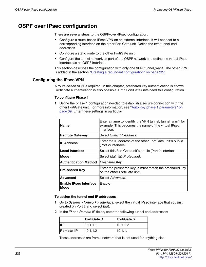
OSPF over IPsec configuration Protecting OSPF with IPsec
OSPF over IPsec configuration
There are several steps to the OSPF-over-IPsec configuration:
• Configure a route-based IPsec VPN on an external interface. It will connect to a
corresponding interface on the other FortiGate unit. Define the two tunnel-end
addresses.
• Configure a static route to the other FortiGate unit.
• Configure the tunnel network as part of the OSPF network and define the virtual IPsec
interface as an OSPF interface.
This section describes the configuration with only one VPN, tunnel_wan1. The other VPN
is added in the section “Creating a redundant configuration” on page 227.
Configuring the IPsec VPN
A route-based VPN is required. In this chapter, preshared key authentication is shown.
Certificate authentication is also possible. Both FortiGate units need this configuration.
To configure Phase 1
1 Define the phase 1 configuration needed to establish a secure connection with the
other FortiGate unit. For more information, see “Auto Key phase 1 parameters” on
page 39. Enter these settings in particular:
To assign the tunnel end IP addresses
1 Go to System > Network > Interface, select the virtual IPsec interface that you just
created on Port 2 and select Edit.
2 In the IP and Remote IP fields, enter the following tunnel end addresses:
These addresses are from a network that is not used for anything else.
Name
Enter a name to identify the VPN tunnel, tunnel_wan1 for
example. This becomes the name of the virtual IPsec
interface.
Remote Gateway Select Static IP Address.
IP AddressEnter the IP address of the other FortiGate unit’s public
(Port 2) interface.
Local Interface Select this FortiGate unit’s public (Port 2) interface.
Mode Select Main (ID Protection).
Authentication Method Preshared Key
Pre-shared KeyEnter the preshared key. It must match the preshared key
on the other FortiGate unit.
Advanced Select Advanced.
Enable IPsec Interface
Mode
Enable
FortiGate_1 FortiGate_2
IP 10.1.1.1 10.1.1.2
Remote_IP 10.1.1.2 10.1.1.1
IPsec VPNs for FortiOS 4.0 MR3
222 01-434-112804-20120111
http://docs.fortinet.com/

Protecting OSPF with IPsec OSPF over IPsec configuration
F
0
h
To configure Phase 2
1 Define the phase 2 parameters needed to create a VPN tunnel with the remote peer.
For more information, see “Phase 2 parameters” on page 57. Enter these settings in
particular:
Configuring static routing
You need to define the route for traffic leaving the external interface. Go to Router > Static
> Static Route, select Create New, and enter the following information.
Configuring OSPF
This section does not attempt to explain OSPF router configuration. It focusses on the
integration of the IPsec tunnel into the OSPF network. This is accomplished by assigning
the tunnel as an OSPF interface, creating an OSPF route to the other FortiGate unit.
This configuration uses loopback interfaces to ease OSPF troubleshooting. The OSPF
router ID is set to the loopback interface address.The loopback interface ensures the
router is always up. Even though technically the router ID doesn’t have to match a valid IP
address on the FortiGate unit, having an IP that matches the router ID makes
troubleshooting a lot easier.
The two FortiGate units have slightly different configurations. FortiGate_1 is an AS border
router that advertises its static default route. FortiGate_2 advertises its local LAN as an
OSPF internal route.
Setting the router ID for each FortiGate unit to the lowest possible value is useful if you
want the FortiGate units to be the designated router (DR) for their respective ASes. This is
the router that broadcasts the updates for the AS.
Leaving the IP address on the OSPF interface at 0.0.0.0 indicates that all potential routes
will be advertised, and it will not be limited to any specific subnet. For example if this IP
address was 10.1.0.0, then only routes that match that subnet will be advertised through
this interface in OSPF.
FortiGate_1 OSPF configurationWhen configuring FortiGate_1 for OSPF, the loopback interface is created, and then you
configure OSPF area networks and interfaces.
With the exception of creating the loopback interface, OSPF for this example can all be
configured in either the web-based manager or CLI.
NameEnter a name to identify this phase 2 configuration, twan1_p2, for
example.
Phase 1Select the name of the phase 1 configuration that you defined in Step 1,
tunnel_wan1 for example.
Destination IP/Mask Leave as 0.0.0.0 0.0.0.0.
Device Select the external interface.
Gateway Enter the IP address of the next hop router.
Distance Leave setting at default value.
ortiOS™ Handbook v3: IPsec VPNs
1-434-112804-20120111 223ttp://docs.fortinet.com/
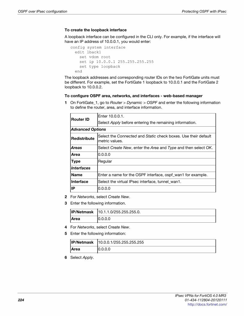
OSPF over IPsec configuration Protecting OSPF with IPsec
To create the loopback interface
A loopback interface can be configured in the CLI only. For example, if the interface will
have an IP address of 10.0.0.1, you would enter:
config system interfaceedit lback1set vdom rootset ip 10.0.0.1 255.255.255.255set type loopback
end
The loopback addresses and corresponding router IDs on the two FortiGate units must
be different. For example, set the FortiGate 1 loopback to 10.0.0.1 and the FortiGate 2
loopback to 10.0.0.2.
To configure OSPF area, networks, and interfaces - web-based manager
1 On FortiGate_1, go to Router > Dynamic > OSPF and enter the following information
to define the router, area, and interface information.
2 For Networks, select Create New.
3 Enter the following information.
4 For Networks, select Create New.
5 Enter the following information:
6 Select Apply.
Router IDEnter 10.0.0.1.
Select Apply before entering the remaining information.
Advanced Options
RedistributeSelect the Connected and Static check boxes. Use their default
metric values.
Areas Select Create New, enter the Area and Type and then select OK.
Area 0.0.0.0
Type Regular
Interfaces
Name Enter a name for the OSPF interface, ospf_wan1 for example.
Interface Select the virtual IPsec interface, tunnel_wan1.
IP 0.0.0.0
IP/Netmask 10.1.1.0/255.255.255.0.
Area 0.0.0.0
IP/Netmask 10.0.0.1/255.255.255.255
Area 0.0.0.0
IPsec VPNs for FortiOS 4.0 MR3
224 01-434-112804-20120111
http://docs.fortinet.com/
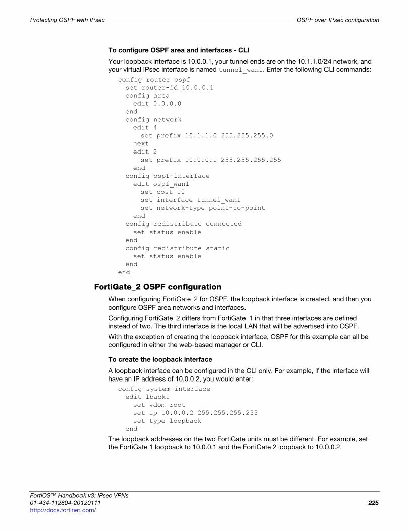
Protecting OSPF with IPsec OSPF over IPsec configuration
F
0
h
To configure OSPF area and interfaces - CLI
Your loopback interface is 10.0.0.1, your tunnel ends are on the 10.1.1.0/24 network, and
your virtual IPsec interface is named tunnel_wan1. Enter the following CLI commands:
config router ospfset router-id 10.0.0.1config areaedit 0.0.0.0
endconfig networkedit 4set prefix 10.1.1.0 255.255.255.0
nextedit 2set prefix 10.0.0.1 255.255.255.255
endconfig ospf-interfaceedit ospf_wan1set cost 10set interface tunnel_wan1set network-type point-to-point
endconfig redistribute connectedset status enable
endconfig redistribute staticset status enable
endend
FortiGate_2 OSPF configurationWhen configuring FortiGate_2 for OSPF, the loopback interface is created, and then you
configure OSPF area networks and interfaces.
Configuring FortiGate_2 differs from FortiGate_1 in that three interfaces are defined
instead of two. The third interface is the local LAN that will be advertised into OSPF.
With the exception of creating the loopback interface, OSPF for this example can all be
configured in either the web-based manager or CLI.
To create the loopback interface
A loopback interface can be configured in the CLI only. For example, if the interface will
have an IP address of 10.0.0.2, you would enter:
config system interfaceedit lback1set vdom rootset ip 10.0.0.2 255.255.255.255set type loopback
end
The loopback addresses on the two FortiGate units must be different. For example, set
the FortiGate 1 loopback to 10.0.0.1 and the FortiGate 2 loopback to 10.0.0.2.
ortiOS™ Handbook v3: IPsec VPNs
1-434-112804-20120111 225ttp://docs.fortinet.com/
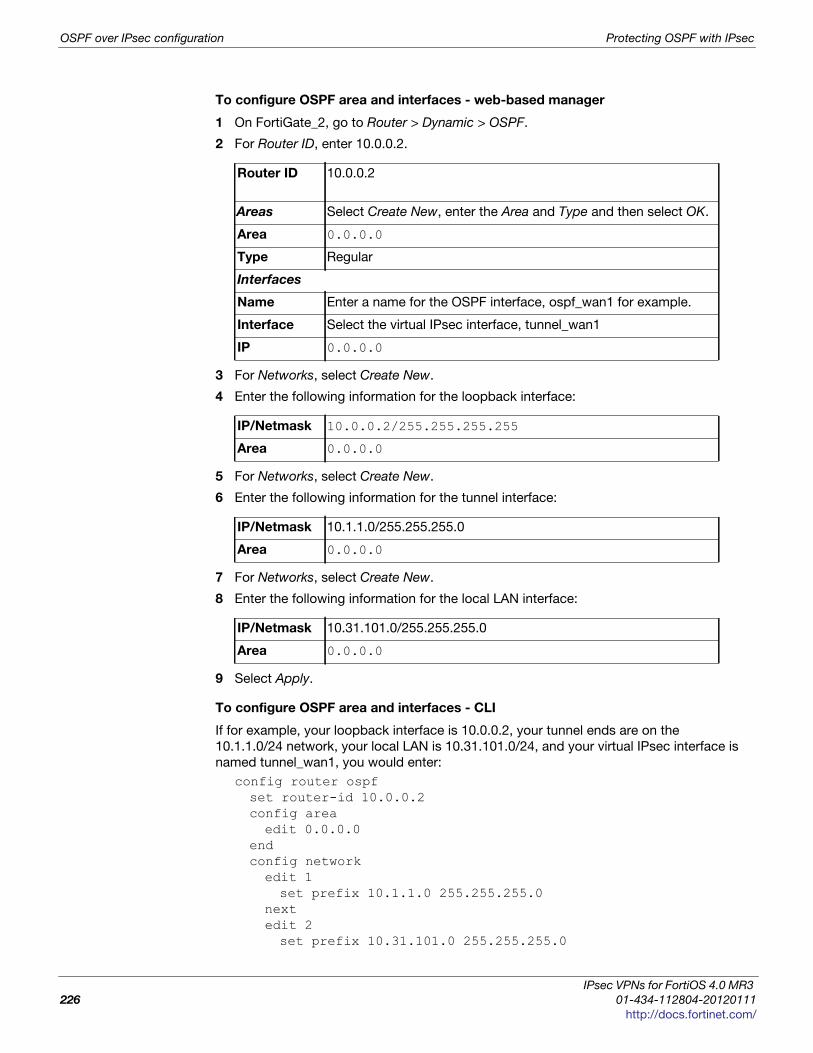
OSPF over IPsec configuration Protecting OSPF with IPsec
To configure OSPF area and interfaces - web-based manager
1 On FortiGate_2, go to Router > Dynamic > OSPF.
2 For Router ID, enter 10.0.0.2.
3 For Networks, select Create New.
4 Enter the following information for the loopback interface:
5 For Networks, select Create New.
6 Enter the following information for the tunnel interface:
7 For Networks, select Create New.
8 Enter the following information for the local LAN interface:
9 Select Apply.
To configure OSPF area and interfaces - CLI
If for example, your loopback interface is 10.0.0.2, your tunnel ends are on the
10.1.1.0/24 network, your local LAN is 10.31.101.0/24, and your virtual IPsec interface is
named tunnel_wan1, you would enter:
config router ospfset router-id 10.0.0.2config areaedit 0.0.0.0
endconfig networkedit 1set prefix 10.1.1.0 255.255.255.0
nextedit 2set prefix 10.31.101.0 255.255.255.0
Router ID 10.0.0.2
Areas Select Create New, enter the Area and Type and then select OK.
Area 0.0.0.0
Type Regular
Interfaces
Name Enter a name for the OSPF interface, ospf_wan1 for example.
Interface Select the virtual IPsec interface, tunnel_wan1
IP 0.0.0.0
IP/Netmask 10.0.0.2/255.255.255.255
Area 0.0.0.0
IP/Netmask 10.1.1.0/255.255.255.0
Area 0.0.0.0
IP/Netmask 10.31.101.0/255.255.255.0
Area 0.0.0.0
IPsec VPNs for FortiOS 4.0 MR3
226 01-434-112804-20120111
http://docs.fortinet.com/

Protecting OSPF with IPsec Creating a redundant configuration
F
0
h
nextedit 2set prefix 10.0.0.2 255.255.255.255
endconfig ospf-interfaceedit ospf_wan1set interface tunnel_wan1set network-type point-to-point
endend
Creating a redundant configuration
You can improve the reliability of the OSPF over IPsec configuration described in the
previous section by adding a second IPsec tunnel to use if the default one goes down.
Redundancy in this case is not controlled by the IPsec VPN configuration but by the
OSPF routing protocol.
To do this you:
• Create a second route-based IPsec tunnel on a different interface and define tunnel
end addresses for it.
• Add the tunnel network as part of the OSPF network and define the virtual IPsec
interface as an additional OSPF interface.
• Set the OSPF cost for the added OSPF interface to be significantly higher than the
cost of the default route.
Adding the second IPsec tunnel
The configuration is the same as in “Configuring the IPsec VPN” on page 222, but the
interface and addresses will be different. Ideally, the network interface you use is
connected to a different Internet service provider for added redundancy.
When adding the second tunnel to the OSPF network, choose another unused subnet for
the tunnel ends, 10.1.2.1 and 10.1.2.2 for example.
Adding the OSPF interface
OSPF uses the metric called cost when determining the best route, with lower costs
being preferred. Up to now in this example, only the default cost of 10 has been used.
Cost can be set only in the CLI.
The new IPsec tunnel will have its OSPF cost set higher than that of the default tunnel to
ensure that it is only used if the first tunnel goes down. The new tunnel could be set to a
cost of 200 compared to the default cost is 10. Such a large difference in cost will ensure
this new tunnel will only be used as a last resort.
If the new tunnel is called tunnel_wan2, you would enter the following on both FortiGate
units:
config router ospfconfig ospf-interfaceedit ospf_wan2set cost 200set interface tunnel_wan2set network-type point-to-point
endend
ortiOS™ Handbook v3: IPsec VPNs
1-434-112804-20120111 227ttp://docs.fortinet.com/

Creating a redundant configuration Protecting OSPF with IPsec
IPsec VPNs for FortiOS 4.0 MR3
228 01-434-112804-20120111
http://docs.fortinet.com/

F o r t i O S H a n d b o o k
F
0
h
Hardware offloading and acceleration
FortiGate units incorporate proprietary FortiASIC NP2 network processors that can
provide accelerated processing for IPsec VPN traffic. This section describes how to
configure offloading and acceleration.
The following topics are included in this section:
• Overview
• IPsec offloading configuration examples
Overview
Fortinet’s NP2 network processors contain features to improve IPsec tunnel
performance. For example, network processors can encrypt and decrypt packets,
offloading cryptographic work from the FortiGate unit’s main processing resources.
On FortiGate units with the appropriate hardware, you can configure offloading of both
IPsec sessions and HMAC checking.
IPsec session offloading requirements
Sessions must be fast path ready. Fast path ready session requirements are:
• Layer 2 type/length must be 0x0800 (IEEE 802.1q VLAN specification is supported);
link aggregation between any network interfaces sharing the same network
processor(s) may be used (IEEE 802.3ad specification is supported)
• Layer 3 protocol must be IPv4
• Layer 4 protocol must be UDP, TCP or ICMP
• Layer 3 / Layer 4 header or content modification must not require a session helper (for
example, SNAT, DNAT, andTTL reduction are supported, but application layer content
modification is not supported)
• FortiGate unit security policy must not require antivirus or IPS inspection, although
hardware accelerated anomaly checks are acceptable.
• The session must not use an aggregated link or require QoS, including rate limits and
bandwidth guarantees (NP1 processor only).
• Ingress and egress network interfaces are both attached to the same network
processor(s)
• In Phase I configuration, Local Gateway IP must be specified as an IP address of a
network interface attached to a network processor
ortiOS™ Handbook v3: IPsec VPNs
1-434-112804-20120111 229ttp://docs.fortinet.com/

Overview Hardware offloading and acceleration
• In Phase II configuration:
• encryption algorithm must be DES, 3DES, AES-128, AES-192, AES-256, or null
(for NP1 processor, only 3DES is supported)
• authentication must be MD5, SHA1, or null
(for NP1 processor, only MD5 is supported)
• if replay detection is enabled, encryption and decryption options must be enabled
in the CLI (see “IPsec encryption offloading”, below)
If the IPsec session meets the above requirements, the FortiGate unit sends the IPsec
security association (SA) and configured processing actions to the network
processors.
Packet offloading requirements
In addition to the session requirements, the packets themselves must meet fast-path
requirements:
• Incoming packets must not be fragmented.
• Outgoing packets must be 385 bytes or larger after any fragmentation. This means the
configured MTU (Maximum Transmission Unit) for the network processors’ interfaces
must have an MTU of 385 bytes or larger.
If packet offloading requirements are not met, an individual packet will use the FortiGate
unit main processing resources, regardless of whether other packets in the session are
offloaded to the specialized network processors.
IPsec encryption offloading
Network processing unit (NPU) settings configure offloading behavior for IPsec VPNs.
Configured behavior applies to all network processors contained by the FortiGate unit
itself or any installed AMC modules.
If replay detection is not enabled (IPsec Phase 2 settings), encryption is always offloaded.
To enable offloading of encryption even when replay detection is enabled
config system npuset enc-offload-antireplay enable
end
To enable offloading of decryption even when replay detection is enabled
config system npuset dec-offload-antireplay enable
end
HMAC check offloading
The Hash-based Message Authentication Code (HMAC) check can also be offloaded to
hardware. SHA-256, SHA-384, or SHA-512 cannot be off-loaded to hardware, and must
be processed using only software resources.
To enable HMAC check offloading
configure system globalset ipsec-hmac-offload (enable|disable)
end
IPsec VPNs for FortiOS 4.0 MR3
230 01-434-112804-20120111
http://docs.fortinet.com/

Hardware offloading and acceleration IPsec offloading configuration examples
F
0
h
IPsec offloading configuration examples
The following examples configure two FortiASIC NP2 accelerated VPNs, one
route-based, the other policy based. In both cases, the network topology is as shown in
Figure 36.
Figure 36: Hardware accelerated IPsec VPN topology
Accelerated route-based VPN configuration
This example uses the accelerated ports on FortiGate-ASM-FB4 modules in each
FortiGate unit. These accelerated ports on the modules are paired interfaces that have
their own network processor (NPU) to offload work from the FortiGate unit CPU. Beyond
this fact, the example is normal VPN example.
Configuring the FortiGate units require the same basic steps:
• Configure VPN Phase 1
• Configure VPN Phase 2
• Create security policies to allow traffic to flow
• Create a static route to allow traffic to flow
When both FortiGates are have the VPN tunnel configured, test to ensure it is working
properly.
To configure FortiGate_1
1 Go to VPN > IPsec > Auto Key (IKE) and select Create Phase 1.
2 Configure Phase 1 settings (name FGT_1_IPsec), plus
• Select Advanced.
• Select Enable IPsec Interface Mode.
• In Local Gateway IP, select Specify and enter the VPN IP address 3.3.3.1, which is
the IP address of FortiGate_1’s FortiGate-ASM-FB4 module on port 2.
3 Select OK.
4 Select Create Phase 2 and configure Phase 2 settings, including
• Select Enable replay detection.
• set enc-offload-antireplay to enable using the config system npu CLI
command.
FortiGate_2FortiG
ate_1
Protected network
ASM-FB4
Port 1
1.1.1.0/24
ASM-FB4
Port 2 (IPsec)
3.3.3.1/24
ASM-FB4Port 2 (IPsec)
3.3.3.2/24ASM-FB4Port 12.2.2.0/24
FoFoFoFoFoFoFoFo trtrtrtrtrtrtiiiGiGiGaa
1111
4
44FoFooortrtrtrttrtiGiGiGiGiGiG tee_22222
A
22
Protected network
ortiOS™ Handbook v3: IPsec VPNs
1-434-112804-20120111 231ttp://docs.fortinet.com/

IPsec offloading configuration examples Hardware offloading and acceleration
5 Go to Policy > Policy > Policy.
6 Configure two policies (one for each direction) to apply the Phase 1 IPsec
configuration you configured in step 2 to traffic leaving from or arriving on FortiGate-
ASM-FB4 module port 1.
7 Go to Router > Static > Static Route.
8 Configure a static route to route traffic destined for FortiGate_2’s protected network to
the virtual IPsec interface, FGT_1_IPsec.
To add the static route from the CLI:
config router staticedit 2set device "FGT_1_IPsec"set dst 2.2.2.0 255.255.255.0
end
To configure FortiGate_2
1 Go to VPN > IPsec > Auto Key (IKE) and select Create Phase 1.
2 Configure Phase 1 settings (name FGT_2_IPsec), plus
• Select Advanced.
• Select Enable IPsec Interface Mode.
• In Local Gateway IP, select Specify and enter the VPN IP address 3.3.3.2, which is
the IP address of FortiGate_2’s FortiGate-ASM-FB4 module on port 2.
3 Select OK.
4 Select Create Phase 2 and configure Phase 2 settings, including
• Select Enable replay detection.
• set enc-offload-antireplay to enable using the config system npu CLI
command.
5 Go to Policy > Policy > Policy.
6 Configure two policies (one for each direction) to apply the Phase 1 IPsec
configuration you configured in step 2 to traffic leaving from or arriving on FortiGate-
ASM-FB4 module port 1.
7 Go to Router > Static > Static Route.
8 Configure a static route to route traffic destined for FortiGate_1’s protected network to
the virtual IPsec interface, FGT_2_IPsec.
To add the static route from the CLI:
config router staticedit 2set device "FGT_2_IPsec"set dst 1.1.1.0 255.255.255.0
end
To test the VPN
1 Activate the IPsec tunnel by sending traffic between the two protected networks.
2 To verify tunnel activation, go to VPN > Monitor > IPsec Monitor.
IPsec VPNs for FortiOS 4.0 MR3
232 01-434-112804-20120111
http://docs.fortinet.com/
Hardware offloading and acceleration IPsec offloading configuration examples
F
0
h
Accelerated policy-based VPN configuration
To configure FortiGate_1
1 Go to VPN > IPsec > Auto Key (IKE) and select Create Phase 1.
2 ConfigurePhase 1 settings (name FGT_1_IPsec), plus
• Select Advanced.
• Ensure that the Enable IPsec Interface Mode check box is not selected.
• In Local Gateway IP, select Specify and enter the VPN IP address 3.3.3.1, which is
the IP address of FortiGate_1’s FortiGate-ASM-FB4 module on port 2.
3 Select OK.
4 SelectCreate Phase 2 and configure Phase 2 settings, including
• Select Enable replay detection.
• set enc-offload-antireplay to enable using the config system npu CLI
command.
5 Go to Policy > Policy > Policy.
6 Configure an IPSEC policy to apply the Phase 1 IPsec tunnel you configured in step 2
to traffic between FortiGate-ASM-FB4 module ports 1 and 2.
7 Go to Router > Static > Static Route.
8 Configure a static route to route traffic destined for FortiGate_2’s protected network to
FortiGate_2’s VPN gateway, 3.3.3.2, through the FortiGate-ASM-FB4 module’s port 2
(device).
To add the static route from the CLI:
config router staticedit 0set device "AMC-SW1/2"set dst 2.2.2.0 255.255.255.0set gateway 3.3.3.1
end
To configure FortiGate_2
1 Go to VPN > IPsec > Auto Key (IKE) and select Create Phase 1.
2 Configure Phase 1 settings (name FGT_2_IPsec), plus
• Select Advanced.
• Select Enable IPsec Interface Mode.
• In Local Gateway IP, select Specify and enter the VPN IP address 3.3.3.2, which is
the IP address of FortiGate_2’s FortiGate-ASM-FB4 module on port 2.
3 Select OK.
4 Select Create Phase 2 and configure Phase 2 settings, including
• Select Enable replay detection.
• set enc-offload-antireplay to enable using the config system npu CLI
command.
5 Go to Policy > Policy > Policy.
6 Configure an IPSEC policy to apply the Phase 1 IPsec tunnel you configured in step 2
to traffic between FortiGate-ASM-FB4 module ports 1 and 2.
7 Go to Router > Static > Static Route.
ortiOS™ Handbook v3: IPsec VPNs
1-434-112804-20120111 233ttp://docs.fortinet.com/

IPsec offloading configuration examples Hardware offloading and acceleration
8 Configure a static route to route traffic destined for FortiGate_1’s protected network to
FortiGate_2’s VPN gateway, 3.3.3.2, through the FortiGate-ASM-FB4 module’s port 2
(device).
To add the static route from the CLI:
config router staticedit 0set device "AMC-SW1/2"set dst 1.1.1.0 255.255.255.0set gateway 3.3.3.2
end
To test the VPN
1 Activate the IPsec tunnel by sending traffic between the two protected networks.
2 To verify tunnel activation, go to VPN > Monitor > IPsec Monitor.
IPsec VPNs for FortiOS 4.0 MR3
234 01-434-112804-20120111
http://docs.fortinet.com/
F o r t i O S H a n d b o o k
F
0
h
Monitoring and troubleshootingThis section provides some general maintenance and monitoring procedures for VPNs.
The following topics are included in this section:
• Monitoring VPN connections
• Testing VPN connections
• Testing VPN connections
• Logging VPN events
• VPN troubleshooting tips
Monitoring VPN connections
You can use the monitor to view activity on IPsec VPN tunnels and to start or stop those
tunnels. The display provides a list of addresses, proxy IDs, and timeout information for
all active tunnels. See “IPsec Monitor” on page 37.
Monitoring connections to remote peers
The list of tunnels provides information about VPN connections to remote peers that have
static IP addresses or domain names. You can use this list to view status and IP
addressing information for each tunnel configuration. You can also start and stop
individual tunnels from the list.
To view the list of static-IP and dynamic-DNS tunnels go toVPN > Monitor > IPsec
Monitor.
Monitoring dialup IPsec connections
The list of dialup tunnels provides information about the status of tunnels that have been
established for dialup clients. The list displays the IP addresses of dialup clients and the
names of all active tunnels. The number of tunnels shown in the list can change as dialup
clients connect and disconnect.
To view the list of dialup tunnels go to VPN > Monitor > IPsec Monitor.
The list of dialup tunnels displays the following statistics:
• The Name column displays the name of the tunnel.
• The meaning of the value in the Remote gateway column changes, depending on the
configuration of the network at the far end:
If you take down an active tunnel while a dialup client such as FortiClient is still
connected, FortiClient will continue to show the tunnel connected and idle. The dialup
client must disconnect before another tunnel can be initiated.
ortiOS™ Handbook v3: IPsec VPNs
1-434-112804-20120111 235ttp://docs.fortinet.com/
Testing VPN connections Monitoring and troubleshooting
• When a FortiClient dialup client establishes a tunnel, the Remote gateway column
displays either the public IP address and UDP port of the remote host device (on
which the FortiClient Endpoint Security application is installed), or if a NAT device
exists in front of the remote host, the Remote gateway column displays the public
IP address and UDP port of the remote host.
• When a FortiGate dialup client establishes a tunnel, the Remote gateway column
displays the public IP address and UDP port of the FortiGate dialup client.
• The Username column displays the peer ID, certificate name, or XAuth user name of
the dialup client (if a peer ID, certificate name, or XAuth user name was assigned to
the dialup client for authentication purposes).
• The Timeout column displays the time before the next key exchange. The time is
calculated by subtracting the time elapsed since the last key exchange from the
keylife.
• The Proxy ID Source column displays the IP addresses of the hosts, servers, or
private networks behind the FortiGate unit. A network range may be displayed if the
source address in the security encryption policy was expressed as a range of IP
addresses.
• The meaning of the value in the Proxy ID Destination column changes, depending on
the configuration of the network at the far end:
• When a FortiClient dialup client establishes a tunnel:
• If VIP addresses are not used and the remote host connects to the Internet
directly, the Proxy ID Destination field displays the public IP address of the
Network Interface Card (NIC) in the remote host.
• If VIP addresses are not used and the remote host is behind a NAT device, the
Proxy ID Destination field displays the private IP address of the NIC in the
remote host.
• If VIP addresses were configured (manually or through FortiGate DHCP relay),
the Proxy ID Destination field displays either the VIP address belonging to a
FortiClient dialup client, or a subnet address from which VIP addresses were
assigned.
• When a FortiGate dialup client establishes a tunnel, the Proxy ID Destination field
displays the IP address of the remote private network.
Testing VPN connections
A VPN connection has multiple stages that can be confirmed to ensure the connection is
working properly. It is easiest to see if the final stage is successful first since if it is
successful the other stages will be working properly. Otherwise, you will need to work
back through the stages to see where the problem is located.
• Testing VPN connection
• Troubleshooting VPN connections
Testing VPN connection
When a VPN connection is properly established, traffic will flow from one end to the other
as if both ends were physically in the same place. If you can determine the connection is
working properly then any problems are likely problems with your applications.
If the connection is not working properly, you can move on to “Troubleshooting VPN
connections” on page 237 to determine the exact problem.
IPsec VPNs for FortiOS 4.0 MR3
236 01-434-112804-20120111
http://docs.fortinet.com/
Monitoring and troubleshooting Testing VPN connections
F
0
h
LAN interface connectionTo confirm whether a VPN connection over LAN interfaces has been configured correctly,
issue a ping or traceroute command on the network behind the FortiGate unit to test the
connection to a computer on the remote network. If the connection is properly
configured, a VPN tunnel will be established automatically when the first data packet
destined for the remote network is intercepted by the FortiGate unit.
If the ping or traceroute fail, it indicates a connection problem between the two ends of
the tunnel. This may or may not indicate problems with the VPN tunnel. You can confirm
this by going to VPN > Monitor > IPsec Monitor where you will be able to see your
connection. A green arrow means the tunnel is up and currently processing traffic. A red
arrow means the tunnel is not processing traffic, and this VPN connection has a problem.
If the connection has problems, see “Troubleshooting VPN connections” on page 237.
Dialup connectionA dialup VPN connection has additional steps. To confirm that a VPN between a local
network and a dialup client has been configured correctly, at the dialup client, issue a
ping command to test the connection to the local network. The VPN tunnel initializes
when the dialup client attempts to connect.
If the ping or traceroute fail, it indicates a connection problem between the two ends of
the tunnel. This may or may not indicate problems with the VPN tunnel, or dialup client.
As with the LAN connection, confirm the VPN tunnel is established by checking VPN >
Monitor > IPsec Monitor.
If the connection has problems, see Troubleshooting.
Troubleshooting VPN connections
If you have determined that your VPN connection is not working properly through
“Testing VPN connection” on page 236, the next step is to verify that you have a phase2
connection.
Testing phase 1 and 2 connections is a bit more difficult than testing the working VPN.
This is because they require diagnose CLI commands. These commands are typically
used by Fortinet customer support to discover more information about your FortiGate
unit and its current configuration.
Before you start troubleshooting you need to:
• configure FortiGate units on both ends for interface VPN
• record the information in your VPN phase 1 and phase 2 configurations - for our
example here the remote IP address is 10.101.101.101.101 and the names of the
phases are Phase1 and Phase2
• install a telnet or SSH client such as putty that allows logging of output
• ensure that the admin interface supports your chosen connection protocol so you can
connect to your FortiGate unit admin interface.
• For this example, default values were used unless stated otherwise.
If traffic is not passing through the FortiGate unit as you expect, ensure the traffic does
not contain IPcomp packets (IP protocol 108, RFC 3173). FortiGate units do not allow
IPcomp packets, they compress packet payload, preventing it from being scanned.
ortiOS™ Handbook v3: IPsec VPNs
1-434-112804-20120111 237ttp://docs.fortinet.com/

Testing VPN connections Monitoring and troubleshooting
To get diagnose information for the VPN connection - CLI
1 Log into the CLI as admin with the output being logged to a file.
2 Stop any diag debug sessions that are currently running with the CLI command
diag debug disable
3 Clear any existing log-filters by running
diag debug log-filter clear
4 Set the log-filter to the IP address of the remote computer (10.11.101.10). This filters
out all VPN connections except ones to the IP address we are concerned with. The
command is
diag debug log-filter dst-addr4 10.11.101.10.
5 Set up the commands to output the VPN handshaking. The commands are:
diag debug app ike 255diag debug enable
6 Have the remote FortiGate initiate the VPN connection in the web-based manager by
going to VPN > Monitor and selecting Bring up.
This makes the remote FortiGate the initiator and the local FortiGate becomes the
responder. Establishing the connection in this manner means the local FortiGate will
have its configuration information as well as the information the remote computer
sends. Having both sets of information locally makes it easier to troubleshoot your
VPN connection.
7 Watch the screen for output, and after roughly 15 seconds enter the following CLI
command to stop the output.
diag debug disable
8 If needed, save the log file of this output to a file on your local computer.
Saving the output to a file can make it easier to search for a particular phrase, or save
the output for future comparison with different output.
To troubleshoot a phase1 VPN connection
Using the output from “To get diagnose information for the VPN connection - CLI” on
page 238, search for the word proposal in the output. It may occur once indicating a
successful connection, or it will occur two or more times for an unsuccessful connection
— there will be one proposal listed for each end of the tunnel and each possible
combination in their settings. For example if 10.11.101.10 selected both DH Group 1 and
5, that would be at least 2 proposals set.
A successful negotiation proposal will look similar to
• XXX insert output sample here XXX
Note the phrases “initiator: main mode is sending 1st message...” and “”
which show you the handshake between the ends of the tunnel is in progress. Initiator
shows the remote unit is sending the first message.
In the proposal you will see the Diffie-Hellman Group (DH Group) listed as OAKLEY and
vn=<a number>. This is normal.
IPsec VPNs for FortiOS 4.0 MR3
238 01-434-112804-20120111
http://docs.fortinet.com/

Monitoring and troubleshooting Logging VPN events
F
0
h
Logging VPN events
You can configure the FortiGate unit to log VPN events. For IPsec VPNs, phase 1 and
phase 2 authentication and encryption events are logged. For information about how to
interpret log messages, see the FortiGate Log Message Reference.
To log VPN events
1 Go to Log&Report > Log Config > Log Setting.
2 Enable the storage of log messages to one or more of the following locations:
• a FortiLog unit
• the FortiGate system memory
• a remote computer running a syslog server
3 If the options are concealed, select the blue arrow beside each option to reveal and
configure associated settings.
4 If logs will be written to system memory, from the Log Level list, select Information.
For more information, see the Logging and Reporting Guide.
5 Select Apply.
To filter VPN events
1 Go to Log&Report > Log Config > Log Setting.
2 Verify that the IPsec negotiation event option is selected.
3 Select Apply.
To view event logs
1 Go to Log&Report > Log & Archive Access > Event Log.
2 If the option is available from the Type list, select the log file from disk or memory.
Entries similar to the following indicate that a tunnel has been established. The following
log messages concern a VPN tunnel called vpn_test on port2 interface in the root
VDOM. Pay attention to the status and msg values.
2005-03-31 15:38:29 log_id=0101023004 type=event subtype=ipsec pri=notice vd=root loc_ip=172.16.62.10 loc_port=500 rem_ip=172.16.62.11 rem_port=500 out_if=port2 vpn_tunnel=vpn_test cookies=151c3a5c6dd93c54/0000000000000000 action=negotiate init=local mode=main stage=1 dir=outbound status=success msg="Initiator: sent 172.16.62.11 main mode message #1 (OK)"
2005-03-31 15:38:29 log_id=0101023004 type=event subtype=ipsec pri=notice vd=root loc_ip=172.16.62.10 loc_port=500 rem_ip=172.16.62.11 rem_port=500 out_if=port2 vpn_tunnel=vpn_test cookies=151c3a5c6dd93c54/5ed26a81fb7a2d0c action=negotiate init=local mode=main stage=2 dir=outbound status=success msg="Initiator: sent 172.16.62.11 main mode message #2 (OK)"
If available on your FortiGate unit, you can enable the storage of log messages to a
system hard disk. In addition, as an alternative to the options listed above, you may
choose to forward log messages to a remote computer running a WebTrends firewall
reporting server. For more information about enabling either of these options through CLI
commands, see the “log” chapter of the FortiGate CLI Reference.
ortiOS™ Handbook v3: IPsec VPNs
1-434-112804-20120111 239ttp://docs.fortinet.com/

Logging VPN events Monitoring and troubleshooting
2005-03-31 15:38:29 log_id=0101023004 type=event subtype=ipsec pri=notice vd=root loc_ip=172.16.62.10 loc_port=500 rem_ip=172.16.62.11 rem_port=500 out_if=port2 vpn_tunnel=vpn_test cookies=151c3a5c6dd93c54/5ed26a81fb7a2d0c action=negotiate init=local mode=main stage=3 dir=outbound status=success msg="Initiator: sent 172.16.62.11 main mode message #3 (OK)"
2005-03-31 15:38:29 log_id=0101023004 type=event subtype=ipsec pri=notice vd=root loc_ip=172.16.62.10 loc_port=500 rem_ip=172.16.62.11 rem_port=500 out_if=port2 vpn_tunnel=vpn_test cookies=151c3a5c6dd93c54/5ed26a81fb7a2d0c action=negotiate init=local mode=main stage=3 dir=inbound status=success msg="Initiator: parsed 172.16.62.11 main mode message #3 (DONE)"
2005-03-31 15:38:29 log_id=0101023004 type=event subtype=ipsec pri=notice vd=root loc_ip=172.16.62.10 loc_port=500 rem_ip=172.16.62.11 rem_port=500 out_if=port2 vpn_tunnel=vpn_test cookies=151c3a5c6dd93c54/5ed26a81fb7a2d0c action=negotiate init=local mode=quick stage=1 dir=outbound status=success msg="Initiator: sent 172.16.62.11 quick mode message #1 (OK)"
2005-03-31 15:38:29 log_id=0101023006 type=event subtype=ipsec pri=notice vd=root loc_ip=172.16.62.10 loc_port=500 rem_ip=172.16.62.11 rem_port=500 out_if=port2 vpn_tunnel=vpn_test cookies=151c3a5c6dd93c54/5ed26a81fb7a2d0c action=install_sa in_spi=66867f2b out_spi=e22de275 msg="Initiator: tunnel 172.16.62.10/172.16.62.11 install ipsec sa"
2005-03-31 15:38:29 log_id=0101023004 type=event subtype=ipsec pri=notice vd=root loc_ip=172.16.62.10 loc_port=500 rem_ip=172.16.62.11 rem_port=500 out_if=port2 vpn_tunnel=vpn_test cookies=151c3a5c6dd93c54/5ed26a81fb7a2d0c action=negotiate init=local mode=quick stage=2 dir=outbound status=success msg="Initiator: sent 172.16.62.11 quick mode message #2 (DONE)"
2005-03-31 15:38:29 log_id=0101023002 type=event subtype=ipsec pri=notice vd=root loc_ip=172.16.62.10 loc_port=500 rem_ip=172.16.62.11 rem_port=500 out_if=port2 vpn_tunnel=vpn_test cookies=151c3a5c6dd93c54/5ed26a81fb7a2d0c action=negotiate status=success msg="Initiator: tunnel 172.16.62.11, transform=ESP_3DES, HMAC_SHA1"
Entries similar to the following indicate that phase 1 negotiations broke down because
the preshared keys belonging to the VPN peers were not identical. A tunnel was not
established. Pay attention to the status and msg values.
2005-03-31 16:06:39 log_id=0101023003 type=event subtype=ipsec pri=error vd=root loc_ip=192.168.70.2 loc_port=500 rem_ip=192.168.80.2 rem_port=500 out_if=port2 vpn_tunnel=vpn_test2 cookies=3896343ae575f210/0a7ba199149e31e9 action=negotiate status=negotiate_error msg="Negotiate SA Error: probable pre-shared secret mismatch"
For more information about how to interpret error log messages, see the FortiGate Log
Message Reference.
IPsec VPNs for FortiOS 4.0 MR3
240 01-434-112804-20120111
http://docs.fortinet.com/
Monitoring and troubleshooting VPN troubleshooting tips
F
0
h
VPN troubleshooting tips
More in-depth VPN troubleshooting can be found in the Troubleshooting guide.
The VPN proposal is not connectingOne side may attempt to initiate the VPN tunnel unsuccessful. There are a number of
potential reasons for this problem.
Attempting hardware offloading beyond SHA1If you are trying to off-load VPN processing to a network processing unit (NPU),
remember that only SHA1 authentication is supported. For high levels of authentication
such as SHA256, SHA384, and SHA512 hardware offloading is not an option — all VPN
processing must be done in software.
Check Phase 1 proposal settingsEnsure that both sides have at least one Phase 1 proposal in common. Otherwise they
will not connect. If there are many proposals in the list, this will slow down the negotiating
of Phase 1. If its too slow, the connection may timeout before completing. If this happens,
try removing some of the unused proposals.
Ensure you are not using a loopback for the local VPN interfaceThe Local Interface field in Phase 1 VPN configuration cannot not be configured to point
to a loopback interface, or the IPSec tunnel will not be established.
Check your routingIf routing is not properly configured with an entry for the remote end of the VPN tunnel,
traffic will not flow properly. You may need static routes on both ends of the tunnel. If
routing is the problem, the proposal will likely setup properly but no traffic will flow.
Try enabling XAuthIf one end of an attempted VPN tunnel is using XAuth and the other end is not, the
connection attempt will fail. The log messages for the attempted connection will not
mention XAuth is the reason, but when connections are failing it is a good idea to ensure
both ends have the same XAuth settings. If you do not know the other end’s settings
enable or disable XAuth on your end to see if that is the problem.
General troubleshooting tips
Most connection failures are due to a configuration mismatch between the FortiGate unit
and the remote peer. In general, begin troubleshooting an IPsec VPN connection failure
as follows:
1 Ping the remote network or client to verify whether the connection is up. See “Testing
VPN connections” on page 236.
2 Traceroute the remote network or client. If DNS is working, you can use domain
names. Otherwise use IP addresses.
3 Check the routing behind the dialup client. Routing problems may be affecting DHCP.
If this appears to be the case, configure a DHCP relay service to enable DHCP
requests to be relayed to a DHCP server on or behind the FortiGate server.
4 Verify the configuration of the FortiGate unit and the remote peer. Check the following
IPsec parameters:
ortiOS™ Handbook v3: IPsec VPNs
1-434-112804-20120111 241ttp://docs.fortinet.com/
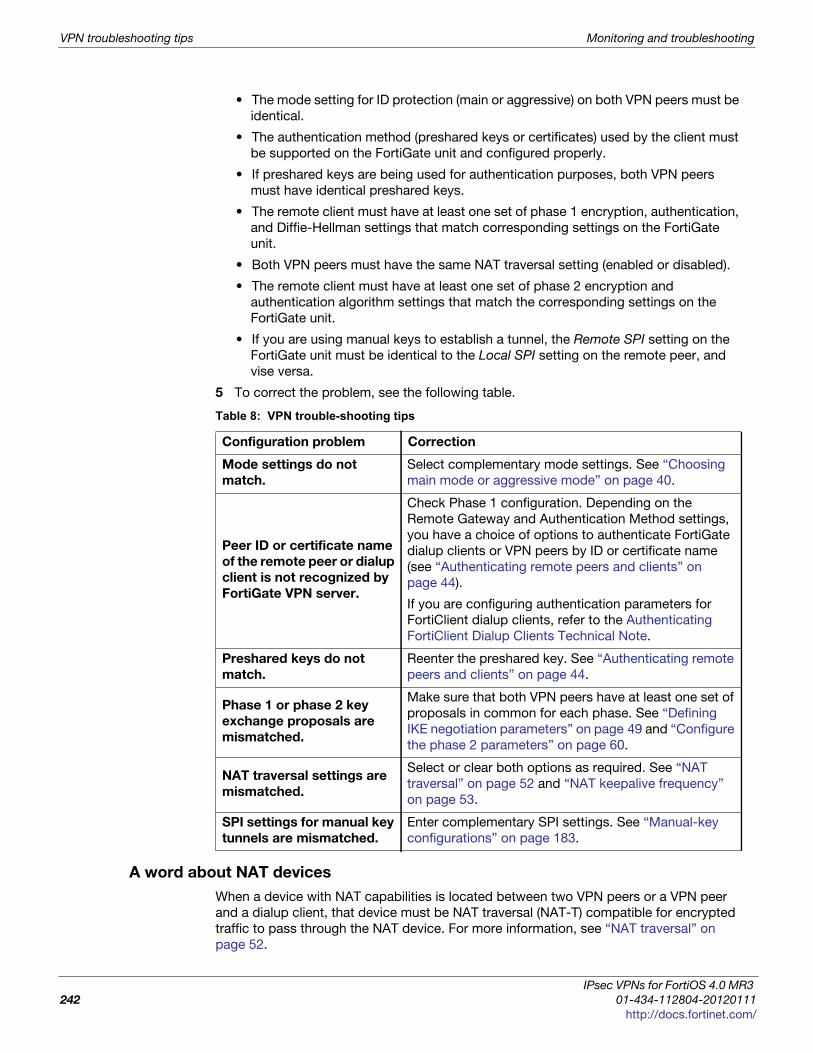
VPN troubleshooting tips Monitoring and troubleshooting
• The mode setting for ID protection (main or aggressive) on both VPN peers must be
identical.
• The authentication method (preshared keys or certificates) used by the client must
be supported on the FortiGate unit and configured properly.
• If preshared keys are being used for authentication purposes, both VPN peers
must have identical preshared keys.
• The remote client must have at least one set of phase 1 encryption, authentication,
and Diffie-Hellman settings that match corresponding settings on the FortiGate
unit.
• Both VPN peers must have the same NAT traversal setting (enabled or disabled).
• The remote client must have at least one set of phase 2 encryption and
authentication algorithm settings that match the corresponding settings on the
FortiGate unit.
• If you are using manual keys to establish a tunnel, the Remote SPI setting on the
FortiGate unit must be identical to the Local SPI setting on the remote peer, and
vise versa.
5 To correct the problem, see the following table.
A word about NAT devices
When a device with NAT capabilities is located between two VPN peers or a VPN peer
and a dialup client, that device must be NAT traversal (NAT-T) compatible for encrypted
traffic to pass through the NAT device. For more information, see “NAT traversal” on
page 52.
Table 8: VPN trouble-shooting tips
Configuration problem Correction
Mode settings do not
match.
Select complementary mode settings. See “Choosing
main mode or aggressive mode” on page 40.
Peer ID or certificate name
of the remote peer or dialup
client is not recognized by
FortiGate VPN server.
Check Phase 1 configuration. Depending on the
Remote Gateway and Authentication Method settings,
you have a choice of options to authenticate FortiGate
dialup clients or VPN peers by ID or certificate name
(see “Authenticating remote peers and clients” on
page 44).
If you are configuring authentication parameters for
FortiClient dialup clients, refer to the Authenticating
FortiClient Dialup Clients Technical Note.
Preshared keys do not
match.
Reenter the preshared key. See “Authenticating remote
peers and clients” on page 44.
Phase 1 or phase 2 key
exchange proposals are
mismatched.
Make sure that both VPN peers have at least one set of
proposals in common for each phase. See “Defining
IKE negotiation parameters” on page 49 and “Configure
the phase 2 parameters” on page 60.
NAT traversal settings are
mismatched.
Select or clear both options as required. See “NAT
traversal” on page 52 and “NAT keepalive frequency”
on page 53.
SPI settings for manual key
tunnels are mismatched.
Enter complementary SPI settings. See “Manual-key
configurations” on page 183.
IPsec VPNs for FortiOS 4.0 MR3
242 01-434-112804-20120111
http://docs.fortinet.com/
F o r t i O S H a n d b o o k
F
0
h
Index
Numerics
3DES-Triple-DES, 51
A
Accept peer certificate, 46Accept this peer certificate
group only, 46adding, configuring defining
IPSec VPN phase 1, 26IPSec VPN phase 1 advanced options, 28IPSec VPN phase 2, 31IPSec VPN phase 2 advanced options, 31
AES128,192 ,256, 51aggregated subnets
for hub-and-spoke VPN, 86aggressive mode, 39Allow inbound, encryption policy, 65Allow outbound, encryption policy, 65ambiguous routing
resolving in FortiGate dialup-client configuration, 134VPN routing, 76
antireplay, 230authenticating
based on peer IDs, 46FortiGate unit pre-shared key, 43IPsec VPN peers and clients, 44through IPsec certificate, 41through XAuth settings, 54
authenticationSHA-1, 256, 384, 512, 51
Authentication AlgorithmManual Key, 184
Authentication Key, Manual Key, 185authentication server, XAuth, 54Autokey
IPSec VPN, 25keep alive, 59Keep Alive, IPsec interface mode, 61
B
backup VPN, 173
C
Certificate Name, Phase 1, 42certificate, IPsec
group, 45Local ID setting, 46using DN to establish access, 44viewing local DN, 45
Challenge-Handshake Authentication Protocol (CHAP), 55Cisco VPN, 211client IP
assigning with RADIUS, 119concentrator, 90
IPSec tunnel mode, 36IPSec VPN, policy-based, 36
configuringdynamic DNS VPN, 104FortiClient dialup-client VPN, 120FortiClient in dialup-client VPN, 125FortiGate dialup-client VPN, 136FortiGate in dialup-client IPsec VPN, 138gateway-to-gateway IPsec VPN, 71hub-and-spoke IPsec VPN, 85manual keys, 184transparent mode IPsec VPN, 179
cryptographic load, 229
D
dead gateway detection, 83Dead Peer Detection (DPD), 53, 83
Phase 1, 52, 53designated router (DR), OSPF, 223DH Group
IPsec interface mode, 61Phase 1, 49, 52Phase 2, 58
DH key size, FIPS-CC, 49DHCP relay
in FortiClient dialup-client configuration, 123in FortiGate dialup client configuration, 135
DHCP server, 59in FortiClient dialup-client configuration, 123
DHCP-IPsecIPsec interface mode, 61IPSec VPN, phase 2, 33phase 2, 59
dialup-client IPsec configurationDHCP server and relay, FortiClient VIP, 123dialup server for FortiClient dialup clients, 120dialup server for FortiGate dialup clients, 136FortiGate client configuration, 138FortiGate dialup client configuration, 136requirements for FortiClient access, 119requirements for FortiGate client access, 135
Diffie-Hellman algorithm, 49, 58Digital Encryption Standard, 17DNS server, dynamic DNS configuration, 104domain name, dynamic DNS configuration, 103, 105
ortiOS™ Handbook v3: IPsec VPNs
1-434-112804-20120111 243ttp://docs.fortinet.com/
Index
Dynamic DNS (DDNS), 101configuration steps, 104domain name configuration, 105overview, 101remote VPN peer configuration, 110
dynamic IP addressfor remote host, 115FortiGate DDNS peer, 103FortiGate dialup client, 133
dynamic VPN addressmode-cfg, 144
dynamic-gateway, 101
E
Enable perfect forward secrecy (PFS)IPsec interface mode, 61Phase 2, 58
Enable replay detectionIPsec interface mode, 61
Enable replay detection, Phase 2, 58Encapsulation, 13Encryption Algorithm
IPSec VPN, manual key, 36Encryption Algorithm, Manual Key, 184Encryption Key, Manual Key, 184encryption policy
allow outbound and inbound, 65defining IP addresses, 63defining IPsec, 66defining multiple for same IPsec tunnel, 67evaluating multiple, 67outbound and inbound NAT, 65traffic direction, 65
exampleshub-and-spoke VPN, 95
Extended Authentication (XAuth), 41, 54, 126extended authentication (XAuth), 42
F
fast pathrequired session characteristics, 229
firewall IP addressesdefining, 63
firewall policydefining for policy-based VPN, 65defining for route-based VPN, 68hub to spoke, 92policy-based, for FortiGate dialup client, 139policy-based, for gateway-to-gateway, 76policy-based, for hub-and-spoke, 89route-based, for FortiGate dialup client, 139route-based, for gateway-to-gateway, 74route-based, for hub-and-spoke, 89spoke to spoke, 93using as route-based "concentrator", 91
FortiASIC, 50, 51NP2, 229
FortiClient dialup client configurationexample, 127
FortiClient dialup-client configurationconfiguration steps, 120FortiClient configuration, 125overview, 115VIP address assignment, 118
Forticlient VPN, 34FortiGate dialup client IPsec configuration
FortiGate acting as client, 133policy-based firewall policy, 139route-based firewall policy, 139using DHCP relay in, 135
fragmented packets, 230
G
gateway-to-gateway IPsec configurationconfiguration steps, 71overview, 69policy-based firewall policy, 76route-based firewall policy, 74
generatingIPsec phase 1 keys, 49IPsec phase 2 keys, 58
GRE-over-IPsec VPN, 211
H
Hash-based Message Authentication Code (HMAC), 49HMAC-MD5, 49HMAC-SHA-1, 49hub-and-spoke
spoke subnet addressing, 86hub-and-spoke IPsec configuration
concentrator, defining, 90configuration example, 95hub configuration, 87infrastructure requirements, 86overview, 85policy-based concentrator, 90policy-based firewall policy, 89route-based firewall policy, 89route-based inter-spoke communication, 90spoke configuration, 92
I
IKE Configuration Method, 144IKE encryption key, 52IKE negotiation
parameters, 49IKEv2, 41Inbound NAT, encryption policy, 65initiator, 82Internet-browsing
configuring FortiClient, 150Internet-browsing firewall policy
VPN server, 148Internet-browsing IPsec configuration
FortiClient dialup-client configuration, 149gateway-to-gateway configuration, 148infrastructure requirements, 147overview, 147
IP protocol 108, 237
IPsec VPNs for FortiOS 4.0 MR3
244 01-434-112804-20120111
http://docs.fortinet.com/

Index
IPcomp, 237IPsec, 230
tunnel, 229IPsec monitor, 37IPSec VPN
adding manual key, 35Autokey list, 25concentrator list, 36configuring phase 1, 26configuring phase 1 advanced options, 28configuring phase 2, 31configuring phase 2 advanced options, 31Manual Key list, 35
IPsec VPNauthentication methods, 44authentication options, 44backup, 173certificates, 44DDNS routing, 101extended authentication (XAuth), 54firewall IP addresses, defining, 63firewall IPsec policy, 65keeping tunnel open, 59logging events, 239manual key, 24monitoring, dialup connection, 235monitoring, static or DDNS connection, 235peer identification, 47phase 1 parameters, 39phase 2 parameters, 57role of encryption policy, 66route-based firewall policy, 68testing, 236troubleshooting, 241
IPv6 IPsec configurationscertificates, 187configuration, 188firewall policies, 188IPv4-over-IPv6 example, 192IPv6-over-IPv4 example, 195IPv6-over-IPv6 example, 189overview, 187phase 1, 188phase 2, 188routing, 188
ISAKMP, 53
K
keepalive, 53Keepalive Frequency, Phase 1, 52, 53Keylife
IPsec interface mode, 61keylife, 58Keylife, Phase 1, 49, 52Keylife, Phase 2, 58
L
L2TPport 1701, 200
L2TP Access Concentrator (LAC), 200
L2TP-over-IPsec, 199Layer 2 Tunneling Protocol (L2TP), 199LDAP server, external
for XAuth, 54life of a packet, 22Local Gateway IP, 229Local ID
for certificates, 46to identify FortiGate dialup clients, 134
Local InterfaceIPSec VPN, manual key, 36
Local SPIIPSec VPN, manual key, 35
Local SPI, Manual Key, 184logging VPN events, 239
M
main mode, 39Manual Key
IPSec VPN, 35manual key IPsec configuration
configuration steps, 184overview, 183
MD5, 230meshed VPN, 69Microsoft Windows, 23Microsoft Windows VPN, 199Mode, Phase 1, 42, 43monitoring
IPsec sessions, 37MTU (Maximum Transmission Unit), 230
N
NameIPSec VPN, manual key, 35
NATkeepalive frequency, 53traversal, 52, 242
Nat-traversal, Phase 1, 52negotiating
IPsec phase 1 parameters, 49IPsec phase 2 parameters, 58
Network Address Translation (NAT), 52network topology
dynamic DNS, 101FortiClient dialup-client, 115FortiGate dialup client, 133fully meshed network, 69gateway-to-gateway, 69hub-and-spoke, 85Internet-browsing, 147manual key, 183partially meshed network, 69redundant-tunnel, 151supported IPsec VPNs, 23transparent mode VPN, 175
NP2 network processor, 229NP2 network processors, 229
IPsec VPNs for FortiOS 4.0 MR3
245 01-434-112804-20120111
http://docs.fortinet.com/
Index
O
OSPFprotecting with IPsec, 221with redundant IPsec tunnels, 227
Outbound NAT, encryption policy, 65overlap
resolving IP address, 134resolving through FortiGate DHCP relay, 134
overlapping VPN subnets, 76
P
P1 Proposal, Phase 1, 49, 51P2 Proposal
IPSec VPN, phase 2, 32P2 Proposal, Phase 2, 58partially meshed VPN, 69Password Authentication Protocol (PAP), 55peer ID
assigning to FortiGate unit, 46enabling, 47
Peer optionIPSec VPN, phase 1, 27
Peer Options, 41perfect forward secrecy (PFS), 80perfect forward secrecy, enabling, 58Phase, 31phase 1
IPSec VPN, 26, 31phase 1 advanced options
IPSec VPN, 28phase 1 parameters
authenticating with certificates, 41authenticating with preshared keys, 42authentication method, 44authentication options, 44defining, 39defining the tunnel ends, 40IKE proposals, 50main or aggressive mode, 40negotiating, 49overview, 39peer identifiers, 46user accounts, 47
phase 2Autokey keep alive, 59IPSec VPN, 31key expires, 58PFS, 80
phase 2 advanced optionsIPSec VPN, 31
phase 2 parametersautokey keep alive, 59auto-negotiate, 58configuring, 60defining, 57DHCP-IPsec, 59keylife, 58negotiating, 58perfect forward secrecy (PFS), 58quick mode selectors, 59replay detection, 58
Phase I, 229Phase II, 230planning VPN configuration, 22policy server, VPN
configuring FortiGate unit as, 123policy-based VPN
vs. route-based, 22port 1701, 200port 4500, 52port 500, 52pre-shared key
authenticating FortiGate unit with, 43preshared key, 17Pre-shared Key, Phase 1, 43proposal
IPSec VPN, phase 2, 32
Q
Quick mode selectors, Phase 2, 59
R
RADIUS, 144assigning client IPs with, 119
RADIUS server, externalfor XAuth, 54
redundant VPNsconfiguration, 152example, fully redundant configuration, 155example, partially-redundant configuration, 166overview, 151
remote clientauthenticating with certificates, 41FortiGate dialup-client, 133in Internet-browsing IPsec configuration, 147
Remote GatewayIPSec manual key setting, 35
remote gatewaydialup user, 59
Remote Gateway, Phase 1, 41, 43remote peer
authenticating with certificates, 41dynamic DNS configuration, 110gateway-to-gateway IPsec configuration, 71manual key configuration, 35manual key IPsec configuration, 183transparent IPsec VPN configuration, 176
Remote SPIIPSec VPN, manual key, 35
Remote SPI, Manual Key, 184replay detection, 230replay detection, enabling, 58RFC 317, 237route-based VPN
firewall policy, 68vs. policy-based, 22
routing, transparent VPN IPsec configuration, 178
S
Security Association (SA), 58, 183
IPsec VPNs for FortiOS 4.0 MR3
246 01-434-112804-20120111
http://docs.fortinet.com/
Index
security association (SA), 230security layer
stateful inspection, 22Security Parameter Index (SPI), 183SHA1, 230SHA-256, 49SHA-256, 384, 512, 51stateful inspection, 22
T
testing VPN connections, 236transparent mode VPN configuration
configuration steps, 179infrastructure requirements, 178overview, 175prerequisites to configuration, 179
transport modesetting, 213
troubleshootVPN, 238
troubleshooting VPNs, 241tunnel
bi-directional initiation, 65
V
viewingIPSec VPN auto key list, 25IPSec VPN concentrator list, 36IPSec VPN manual key list, 35
VIP address, FortiClient dialup clients, 118VIP addresses, 59virtual domain, transparent VPN IPsec configuration, 179virtual IP
assigning with RADIUS, 119
virtual IP address (VIP), 76Virtual Private Network (VPN), 13VPN
backup, 173FortiClient automatic settings, 125FortiClient manual settings, 125logging events, 239monitoring, dialup connection, 235monitoring, static or DDNS connection, 235planning configurations, 22policy-based vs. route-based, 22preparation steps, 24testing, 236troubleshooting, 241
vpninitiator, 82
VPN policy serverconfiguring FortiClient to use, 125configuring FortiGate unit as, 123
VPNsForticlient, 34
W
Windows VPN, 199
X
XAuth (extended authentication)authenticating users with, 54FortiClient application as client, 126FortiGate unit as server, 54
Z
zoneusing as route-based "concentrator", 90
IPsec VPNs for FortiOS 4.0 MR3
247 01-434-112804-20120111
http://docs.fortinet.com/

Index
IPsec VPNs for FortiOS 4.0 MR3
248 01-434-112804-20120111
http://docs.fortinet.com/


