
Market Information MAI 54
double row!New!
Lateral gear t
eeth
Four-row linear recirculating ball bearing and guideway assembliesGuideway with teeth on underside or toothed rack with lateral teeth
For driven guideways, the four-row linear recirculating ball bearing and guideway assemblies KUVE..B ZHP have been available for some time. In these series, the guideways have right hand helical teeth with a mesh angle of 20°. The teeth are aligned downwards, hardened and ground. In comparison with units without teeth, these designs are more precise, allow significantly simpler adjacent constructions and give considerable reductions in fitting and logistical requirements.In order to increase further the potential applications of toothed guideways, the proven range has been expanded to include the series KUVE..B ZHST SVS. These units have a combination of a standard guideway TKVD with a toothed rack ZHST..SVS. Furthermore, the hardened and ground helical teeth are arranged laterally. This gives even more flexible fitting possibilities and increased free space in the design of the adjacent construction.Due to their modular design, the toothed series are suitable for all carriage types (except the wide W designs) and thus can be simply converted.The rolling element system of the guidance systems is lubricated by grease or oil. The teeth can be easily lubricated by means of felt gears and electronically controlled lubricators.The guidance systems can be used across a wide range of temperatures and are most suitable for applications in the handling equipment and automation technology sectors.
205
036

2
Four-row linear recirculating ball bearing and guideway assembliesGuideway with teeth on underside
Page
Ordering example and ordering designation ....... 3
Design and safety guidelines............................... 10
Accessories ......................................................... 10
Features
Four-row linear recirculating ball bearing and guideway assemblies■ of these series are complete units comprising:
– a carriage KWVE..B or KWVE..B KT– a guideway TKVD..ZHP with helical gear teeth on the
underside■ expand on the advantages of units without teeth through:
– considerably reduced fitting work– increased accuracy– simplified design and machining of the adjacent
construction– reduced logistical work
■ are available in sizes 25 and 35■ are of a modular concept, i.e.:
– within one size, toothed guidance units can be combined with all carriage types (exception: wide W designs)
■ can support forces from all directions and moments about all axes
■ are preloaded■ have high load carrying capacity and rigidity■ can also be supplied as a preassembled unit for higher
accuracies■ have integral elastic wipers on the end faces of the
carriage and sealing strips for sealing the carriage■ can be lubricated with oil or grease
– the rolling contact is relubricated by means of a lubrication connector in the end piece of the carriage
– the teeth must be lubricated separately. For example, a felt gear and electronically controlled lubricator can be used
■ are suitable for temperatures from –10 °C to +100 °C■ are highly suitable for applications
– in the handling equipment and automation technology sectors.
Further information on the linear recirculating ball bearing and guideway assemblies: INA Catalogue “Monorail guidance systems” 605 and “MAI 91”, INA-CD-ROM “medias® professional”
Toothed guideway with SB carriage
k0M
˚C
■ carriage KWVE..B SB with lateral fixing holes■ guideway TKVD..ZHP with helical gear teeth on the
underside– tooth grade 6, right hand helical teeth 19º 31� 42�,
hardened and ground, mesh angle 20°
Toothed guideway with H carriage
k0M
˚C
■ carriage KWVE..B H with fixing holes for screw mounting from above
■ guideway TKVD..ZHP with helical gear teeth on the underside– tooth grade 6, right hand helical teeth 19º 31� 42�,
hardened and ground, mesh angle 20°
KUVE..B SB ZHP
172
858
KUVE..B H ZHP17
3 14
5
4
3
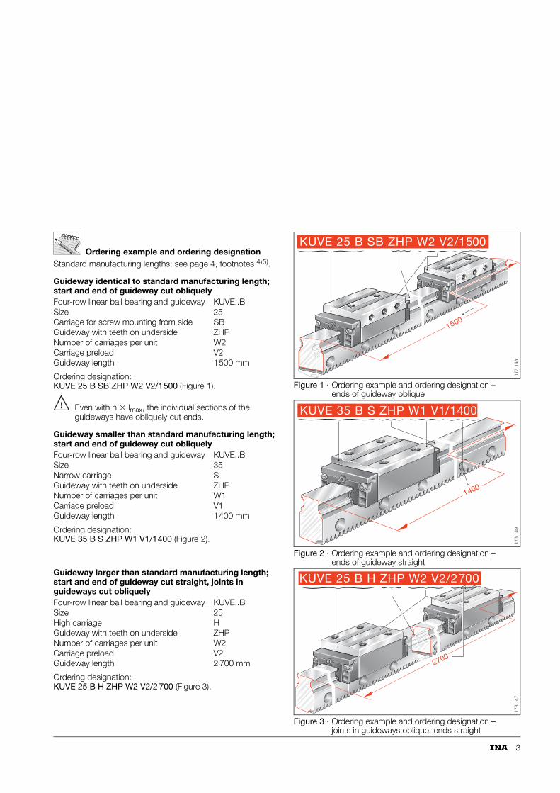
Ordering example and ordering designationStandard manufacturing lengths: see page 4, footnotes 4)5).
Guideway identical to standard manufacturing length; start and end of guideway cut obliquely
Ordering designation: KUVE 25 B SB ZHP W2 V2/1500 (Figure 1).
Even with n � lmax, the individual sections of the guideways have obliquely cut ends.
Guideway smaller than standard manufacturing length; start and end of guideway cut obliquely
Ordering designation:KUVE 35 B S ZHP W1 V1/1400 (Figure 2).
Guideway larger than standard manufacturing length; start and end of guideway cut straight, joints in guideways cut obliquely
Ordering designation: KUVE 25 B H ZHP W2 V2/2 700 (Figure 3).
Figure 1 · Ordering example and ordering designation – ends of guideway oblique
Figure 2 · Ordering example and ordering designation – ends of guideway straight
Figure 3 · Ordering example and ordering designation – joints in guideways oblique, ends straight
Four-row linear ball bearing and guideway KUVE..BSize 25Carriage for screw mounting from side SBGuideway with teeth on underside ZHPNumber of carriages per unit W2Carriage preload V2Guideway length 1500 mm
Four-row linear ball bearing and guideway KUVE..BSize 35Narrow carriage SGuideway with teeth on underside ZHPNumber of carriages per unit W1Carriage preload V1Guideway length 1400 mm
Four-row linear ball bearing and guideway KUVE..BSize 25High carriage HGuideway with teeth on underside ZHPNumber of carriages per unit W2Carriage preload V2Guideway length 2 700 mm
1500
KUVE 25 B SB ZHP W2 V2/1500
173
148
1400
KUVE 35 B S ZHP W1 V1/1400
173
149
2700
KUVE 25 B H ZHP W2 V2/2700
173
147
4
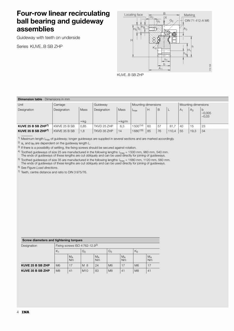
Four-row linear recirculating ball bearing and guideway assembliesGuideway with teeth on underside
Series KUVE..B SB ZHP
KUVE..B SB ZHP
7
3 2
3
14
1
6
1
965
H
H T H
K
h
bA
hH
h
A
GX
BH
G
Locating face Marking
DIN 71 412-A M6
172
726
1) Maximum length lmax of guideway; longer guideways are supplied in several sections and are marked accordingly.2) aL and aR are dependent on the guideway length L.3) If there is a possibility of settling, the fixing screws should be secured against rotation.4) Toothed guideways of size 25 are manufactured in the following lengths: lmax = 1500 mm, 960 mm, 540 mm.
The ends of guideways of these lengths are cut obliquely and can be used directly for joining of guideways.5) Toothed guideways of size 35 are manufactured in the following lengths: lmax = 1680 mm, 1120 mm, 560 mm.
The ends of guideways of these lengths are cut obliquely and can be used directly for joining of guideways.6) See Figure Load directions.7) Teeth, centre distance and ratio to DIN 3 975/76.
Dimension table · Dimensions in mm
Unit Carriage Guideway Mounting dimensions Mounting dimensions
Designation Designation Mass Designation Mass lmax H B L A1 A3 b–0,005–0,03
�kg �kg/m
KUVE 25 B SB ZHP7) KWVE 25 B SB 0,85 TKVD 25 ZHP 6,3 15001)4) 60 57 81,7 40 15 23
KUVE 35 B SB ZHP7) KWVE 35 B SB 1,8 TKVD 35 ZHP 14 16801)5) 85 76 110,4 55 19,3 34
Screw diameters and tightening torques
Designation Fixing screws ISO 4 762-12.93)
K1 G2 G3 K6
MANm
MANm
MANm
MANm
KUVE 25 B SB ZHP M6 17 M 8 24 M6 17 M6 17
KUVE 35 B SB ZHP M8 41 M10 83 M8 41 M8 41
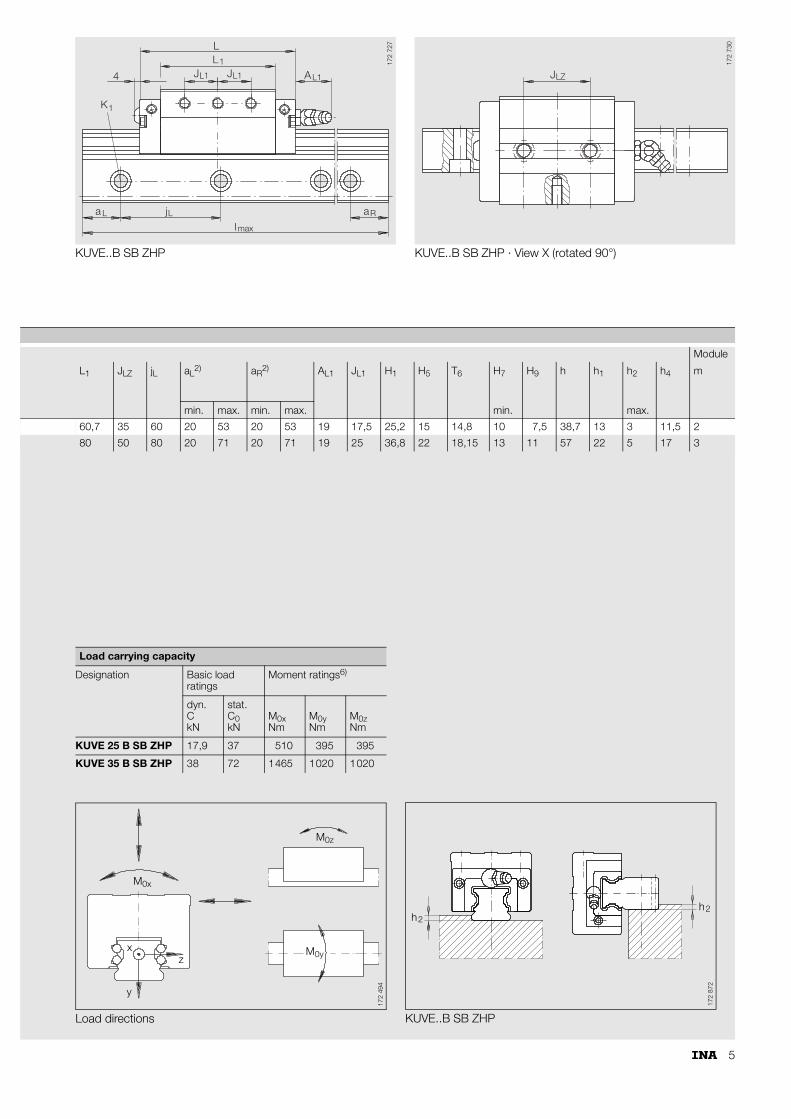
5
KUVE..B SB ZHP KUVE..B SB ZHP · View X (rotated 90°)
L1
1
L L Ra aj
l
A
LL
J L1J1
L14
K
max
172
727
JLZ
172
730
Module
L1 JLZ jL aL2) aR
2) AL1 JL1 H1 H5 T6 H7 H9 h h1 h2 h4 m
min. max. min. max. min. max.
60,7 35 60 20 53 20 53 19 17,5 25,2 15 14,8 10 7,5 38,7 13 3 11,5 2
80 50 80 20 71 20 71 19 25 36,8 22 18,15 13 11 57 22 5 17 3
Load directions KUVE..B SB ZHP
Load carrying capacity
Designation Basic load ratings
Moment ratings6)
dyn.CkN
stat.C0kN
M0xNm
M0yNm
M0zNm
KUVE 25 B SB ZHP 17,9 37 510 395 395
KUVE 35 B SB ZHP 38 72 1465 1020 1020
M
xz
y
0x
M0z
M0y
172
494
h2h2
172
872
6
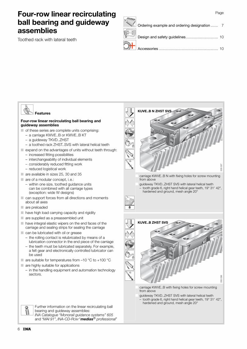
Four-row linear recirculating ball bearing and guideway assembliesToothed rack with lateral teeth
Page
Ordering example and ordering designation ....... 7
Design and safety guidelines............................... 10
Accessories ......................................................... 10
Features
Four-row linear recirculating ball bearing and guideway assemblies■ of these series are complete units comprising:
– a carriage KWVE..B or KWVE..B KT– a guideway TKVD..ZHST– a toothed rack ZHST..SVS with lateral helical teeth
■ expand on the advantages of units without teeth through:– increased fitting possibilities– interchangeability of individual elements– considerably reduced fitting work– reduced logistical work
■ are available in sizes 25, 30 and 35■ are of a modular concept, i.e.:
– within one size, toothed guidance units can be combined with all carriage types (exception: wide W designs)
■ can support forces from all directions and moments about all axes
■ are preloaded■ have high load carrying capacity and rigidity■ are supplied as a preassembled unit■ have integral elastic wipers on the end faces of the
carriage and sealing strips for sealing the carriage■ can be lubricated with oil or grease
– the rolling contact is relubricated by means of a lubrication connector in the end piece of the carriage
– the teeth must be lubricated separately. For example, a felt gear and electronically controlled lubricator can be used
■ are suitable for temperatures from –10 °C to +100 °C■ are highly suitable for applications
– in the handling equipment and automation technology sectors.
Further information on the linear recirculating ball bearing and guideway assemblies: INA Catalogue “Monorail guidance systems” 605 and “MAI 91”, INA-CD-ROM “medias® professional”
k0M
˚C
■ carriage KWVE..B N with fixing holes for screw mounting from above
■ guideway TKVD..ZHST SVS with lateral helical teeth– tooth grade 6, right hand helical gear teeth, 19° 31� 42�,
hardened and ground, mesh angle 20°
k0M
˚C
■ carriage KWVE..B with fixing holes for screw mounting from above
■ guideway TKVD..ZHST SVS with lateral helical teeth– tooth grade 6, right hand helical gear teeth, 19° 31� 42�,
hardened and ground, mesh angle 20°
KUVE..B N ZHST SVS
205
037
KUVE..B ZHST SVS20
5 03
8
8
7
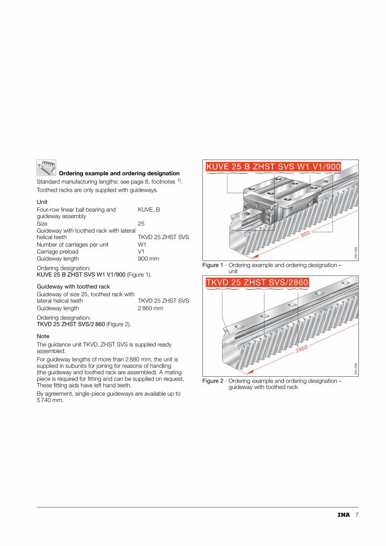
Ordering example and ordering designationStandard manufacturing lengths: see page 8, footnotes 1).Toothed racks are only supplied with guideways.
Unit
Ordering designation: KUVE 25 B ZHST SVS W1 V1/900 (Figure 1).
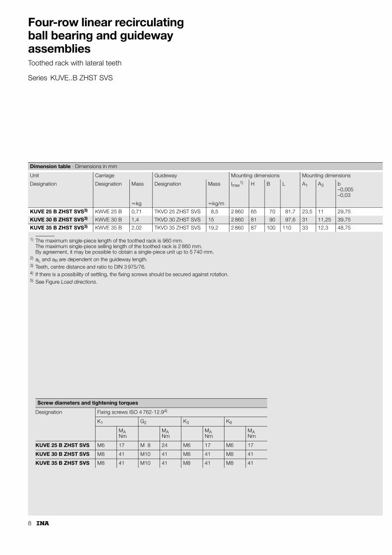
Guideway with toothed rack
Ordering designation: TKVD 25 ZHST SVS/2 860 (Figure 2).
NoteThe guidance unit TKVD..ZHST SVS is supplied ready assembled.For guideway lengths of more than 2 880 mm, the unit is supplied in subunits for joining for reasons of handling (the guideway and toothed rack are assembled). A mating piece is required for fitting and can be supplied on request. These fitting aids have left hand teeth.By agreement, single-piece guideways are available up to 5 740 mm.
Figure 1 · Ordering example and ordering designation – unit
Figure 2 · Ordering example and ordering designation – guideway with toothed rack
Four-row linear ball bearing and guideway assembly
KUVE..B
Size 25Guideway with toothed rack with lateral helical teeth TKVD 25 ZHST SVSNumber of carriages per unit W1Carriage preload V1Guideway length 900 mm
Guideway of size 25, toothed rack with lateral helical teeth TKVD 25 ZHST SVSGuideway length 2 860 mm
KUVE 25 B ZHST SVS W1 V1/900
900
205
039
TKVD 25 ZHST SVS/2860
286020
5 05
8
8
Four-row linear recirculating ball bearing and guideway assembliesToothed rack with lateral teeth
Series KUVE..B ZHST SVS
1) The maximum single-piece length of the toothed rack is 960 mm.The maximum single-piece selling length of the toothed rack is 2 860 mm.By agreement, it may be possible to obtain a single-piece unit up to 5 740 mm.
2) aL and aR are dependent on the guideway length.3) Teeth, centre distance and ratio to DIN 3 975/76.4) If there is a possibility of settling, the fixing screws should be secured against rotation.5) See Figure Load directions.
Dimension table · Dimensions in mm
Unit Carriage Guideway Mounting dimensions Mounting dimensions
Designation Designation Mass Designation Mass lmax1) H B L A1 A3 b
–0,005–0,03
�kg �kg/m
KUVE 25 B ZHST SVS3) KWVE 25 B 0,71 TKVD 25 ZHST SVS 8,5 2 860 65 70 81,7 23,5 11 29,75
KUVE 30 B ZHST SVS3) KWVE 30 B 1,4 TKVD 30 ZHST SVS 15 2 860 81 90 97,6 31 11,25 39,75
KUVE 35 B ZHST SVS3) KWVE 35 B 2,02 TKVD 35 ZHST SVS 19,2 2 860 87 100 110 33 12,3 48,75
Screw diameters and tightening torques
Designation Fixing screws ISO 4 762-12.94)
K1 G2 K3 K6
MANm
MANm
MANm
MANm
KUVE 25 B ZHST SVS M6 17 M 8 24 M6 17 M6 17
KUVE 30 B ZHST SVS M8 41 M10 41 M8 41 M8 41
KUVE 35 B ZHST SVS M8 41 M10 41 M8 41 M8 41
9
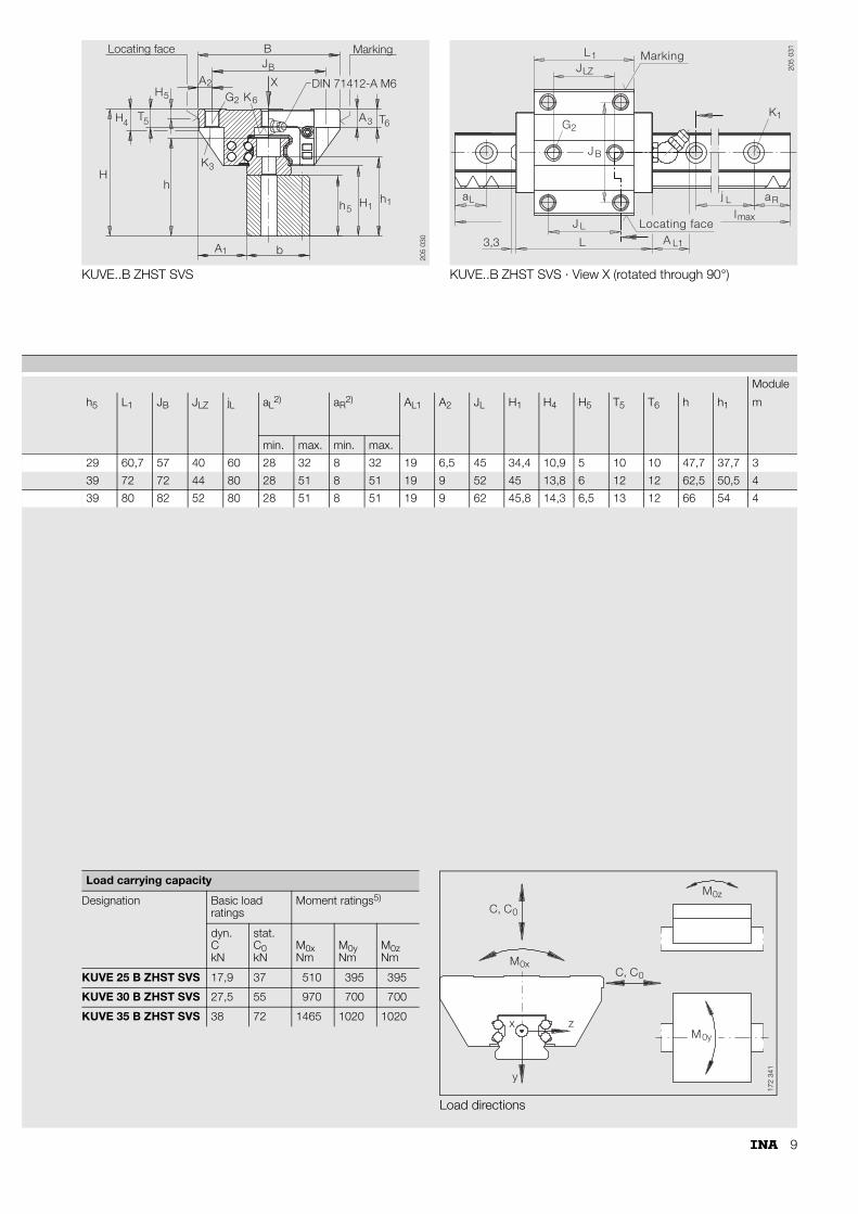
KUVE..B ZHST SVS KUVE..B ZHST SVS · View X (rotated through 90°)
A b1
JB
XG
A
H
H
T
H
h
K
DIN 71412-A M6
T6A3
3
4 5
2
2 K6
B
Locating face Marking
5
h5 H h11
205
030
L1JLZ
Marking
K1
j L aR
lLocating faceJ L
L3,3
aL
A L1
max
G2
J B
205
031
Module
h5 L1 JB JLZ jL aL2) aR
2) AL1 A2 JL H1 H4 H5 T5 T6 h h1 m
min. max. min. max.
29 60,7 57 40 60 28 32 8 32 19 6,5 45 34,4 10,9 5 10 10 47,7 37,7 3
39 72 72 44 80 28 51 8 51 19 9 52 45 13,8 6 12 12 62,5 50,5 4
39 80 82 52 80 28 51 8 51 19 9 62 45,8 14,3 6,5 13 12 66 54 4
Load directions
Load carrying capacity
Designation Basic load ratings
Moment ratings5)
dyn.CkN
stat.C0kN
M0xNm
M0yNm
M0zNm
KUVE 25 B ZHST SVS 17,9 37 510 395 395
KUVE 30 B ZHST SVS 27,5 55 970 700 700
KUVE 35 B ZHST SVS 38 72 1465 1020 1020
M
M
x
y
z
0x
M0y
0z
C, C0
C, C0
172
341
10
Four-row linear recirculating ball bearing and guideway assembliesGuideway with teeth on underside or toothed rack with lateral teeth
Design and safety guidelines
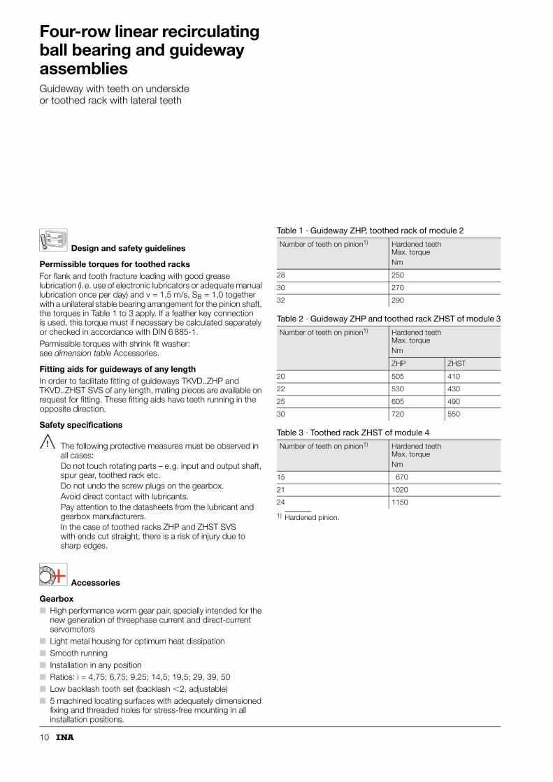
Permissible torques for toothed racksFor flank and tooth fracture loading with good grease lubrication (i.e. use of electronic lubricators or adequate manual lubrication once per day) and v = 1,5 m/s, SB = 1,0 together with a unilateral stable bearing arrangement for the pinion shaft, the torques in Table 1 to 3 apply. If a feather key connection is used, this torque must if necessary be calculated separately or checked in accordance with DIN 6 885-1.Permissible torques with shrink fit washer: see dimension table Accessories.
Fitting aids for guideways of any lengthIn order to facilitate fitting of guideways TKVD..ZHP and TKVD..ZHST SVS of any length, mating pieces are available on request for fitting. These fitting aids have teeth running in the opposite direction.
Safety specifications
The following protective measures must be observed in all cases:Do not touch rotating parts – e.g. input and output shaft, spur gear, toothed rack etc.Do not undo the screw plugs on the gearbox.Avoid direct contact with lubricants.Pay attention to the datasheets from the lubricant and gearbox manufacturers.In the case of toothed racks ZHP and ZHST SVS with ends cut straight, there is a risk of injury due to sharp edges.
Accessories
Gearbox■ High performance worm gear pair, specially intended for the
new generation of threephase current and direct-current servomotors
■ Light metal housing for optimum heat dissipation■ Smooth running■ Installation in any position■ Ratios: i = 4,75; 6,75; 9,25; 14,5; 19,5; 29, 39, 50■ Low backlash tooth set (backlash �2, adjustable)■ 5 machined locating surfaces with adequately dimensioned
fixing and threaded holes for stress-free mounting in all installation positions.
1) Hardened pinion.
Table 1 · Guideway ZHP, toothed rack of module 2
Number of teeth on pinion1) Hardened teeth Max. torqueNm
28 250
30 270
32 290
Table 2 · Guideway ZHP and toothed rack ZHST of module 3
Number of teeth on pinion1) Hardened teeth Max. torqueNm
ZHP ZHST
20 505 410
22 530 430
25 605 490
30 720 550
Table 3 · Toothed rack ZHST of module 4
Number of teeth on pinion1) Hardened teeth Max. torqueNm
15 670
21 1020
24 1150

11
Mounting positionIf the additional forces are to be fully utilised, the gearbox should be flange mounted on the largest locating surfaces.The most favourable mounting position for lubrication is achieved with a lateral or bottom-mounted worm shaft.
With a top-mounted worm shaft, the drive power is reduced by approx. 10%.
Flank backlashThe flank backlash ist set to the smallest possible value at the manufacturing plant. If the backlash changes after a long period of operation, it can be corrected to the specified value by means of the eccentrically supported input shaft.
LubricationThe gearboxes are filled with synthetic lubricant. The filling should be checked monthly and several times in the first weeks of operation.
Under moderate load, the lubricant should be changed between once and four times per year (for single, double or triple shift operation).
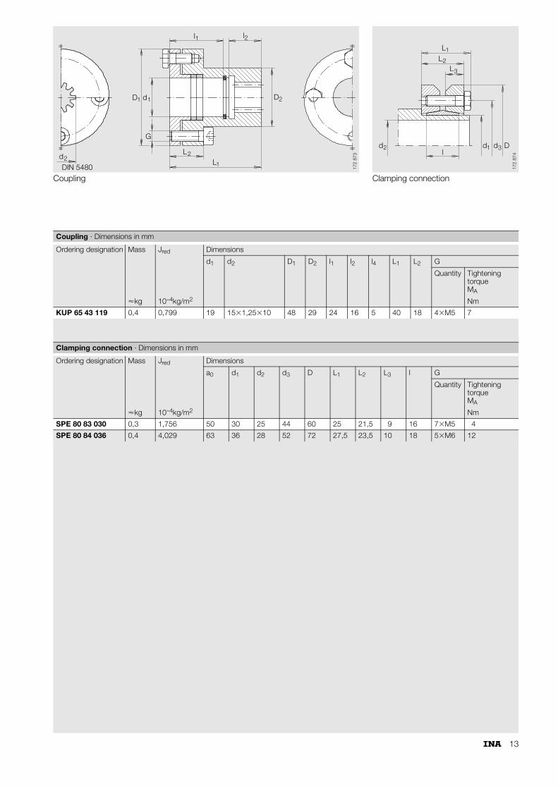
Coupling■ Bore on the gearbox side; backlash-free tooth hub profile
for push mounting – similar to DIN 5 480 (Figure 1, A)■ Bore on the motor side with annular spring elements as
clamping connection (Figure 1, B)■ Preassembled.
Before fixing on the motor shaft as contact surfaces, clean and protect using a light oil film – this prevents fretting corrosion.
Input shafts■ Helical teeth, 19° 31� 42�, mesh angle 20°■ Ground teeth, grade 6 e 25 – similar to DIN 3 962/63/67■ Case hardened.
Before assembly, clean input shafts and lightly grease or oil – this prevents fretting corrosion.
Figure 1 · Coupling
A B
173
008
12
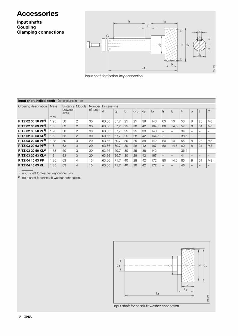
AccessoriesInput shaftsCouplingClamping connections
Input shaft for feather key connection
d
G
2 dd t
b
u
d1
k
l1
L1
l3l2
172
876
1) Input shaft for feather key connection.2) Input shaft for shrink fit washer connection.
Input shaft, helical teeth · Dimensions in mm
Ordering designation Mass Distance between axes
Module Number of teeth
Dimensions
d dk b d1 i6 d2 L1 l1 l2 l3 u t G
�kg
RITZ 02 30 50 PF1) 1,25 50 2 30 63,66 67,7 25 25 38 140 63 13 53 8 28 M8
RITZ 02 30 63 PF1) 1,5 63 2 30 63,66 67,7 25 28 42 164,5 80 14,5 57,5 8 31 M8
RITZ 02 30 50 PF2) 1,25 50 2 30 63,66 67,7 25 25 38 140 – – 34 – – –
RITZ 02 30 63 KL2) 1,6 63 2 30 63,66 67,7 25 28 42 164,5 – – 38,5 – – –
RITZ 03 20 50 PF1) 1,33 50 3 20 63,66 69,7 30 25 38 142 63 13 55 8 28 M8
RITZ 03 20 63 PF1) 1,6 63 3 20 63,66 69,7 30 28 42 167 80 14,5 60 8 31 M8
RITZ 03 20 50 KL2) 1,33 50 3 20 63,66 69,7 30 25 38 142 36,5 – – –
RITZ 03 20 63 KL2) 1,6 63 3 20 63,66 69,7 30 28 42 167 – – 41 – – –
RITZ 04 15 63 PF 1,85 63 4 15 63,66 71,7 40 28 42 172 80 14,5 65 8 31 M8
RITZ 04 16 63 KL 1,85 63 4 15 63,66 71,7 40 28 42 172 – – 46 – – –
Input shaft for shrink fit washer connection
L1
d1 dd
b
k
l 3
d2
172
877
13
Coupling
l1 l2
LDIN 5480 1
D2
L2
D
G
1 d1
d2
172
873
Clamping connection
L1
d2 d1 d Dl
3
L2L3
172
874
Coupling · Dimensions in mm
Ordering designation Mass Jred Dimensions
d1 d2 D1 D2 l1 l2 l4 L1 L2 G
Quantity Tightening torqueMA
�kg 10–4kg/m2 Nm
KUP 65 43 119 0,4 0,799 19 15�1,25�10 48 29 24 16 5 40 18 4�M5 7
Clamping connection · Dimensions in mm
Ordering designation Mass Jred Dimensions
a0 d1 d2 d3 D L1 L2 L3 l G
Quantity Tightening torqueMA
�kg 10–4kg/m2 Nm
SPE 80 83 030 0,3 1,756 50 30 25 44 60 25 21,5 9 16 7�M5 4
SPE 80 84 036 0,4 4,029 63 36 28 52 72 27,5 23,5 10 18 5�M6 12
14
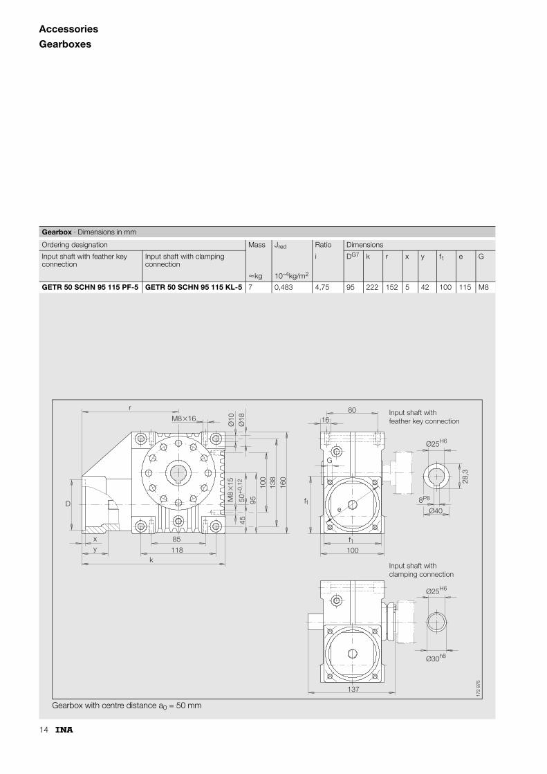
Accessories
Gearboxes
Gearbox · Dimensions in mm
Ordering designation Mass Jred Ratio Dimensions
Input shaft with feather key connection
Input shaft with clamping connection
i DG7 k r x y f1 e G
�kg 10–4kg/m2
GETR 50 SCHN 95 115 PF-5 GETR 50 SCHN 95 115 KL-5 7 0,483 4,75 95 222 152 5 42 100 115 M8
Gearbox with centre distance a0 = 50 mm
172
875
D
Input shaft withfeather key connection
Input shaft withclamping connection
xy
k
r
85
M8 16�
�M
8 1
5
4595
100
138
160 28
,3
Ø10
Ø40
Ø18
50+
0,12
Ø25H6
P8
H6Ø25
h8Ø30
8
118f1
fe
G
1
100
8016
137

15
Gearbox · Dimensions in mm
Ordering designation Mass Jred Ratio Dimensions
Input shaft with feather key connection
Input shaft with clamping connection
i DG7 k r x y f1 e G
�kg 10–4kg/m2
GETR 63 SCHN 130 165 PF-39 GETR 63 SCHN 130 165 KL-39 12 1,01 39 95 265 180 5 48 100 115 M8
Gearbox with centre distance a0 = 63 mm
173
146
D
Input shaft withfeather key connection
Input shaft withclamping connection
xy
k
r
110
M10 15�
�M
10
16
5211
512
517
519
5 31,3
Ø11
24,7
h8
Ø45
Ø18
63+
0,2
Ø72
H8
Ø25H6
P8
H6Ø28
h8Ø36
8
145f1
fe
G
1
130
10525
168
16
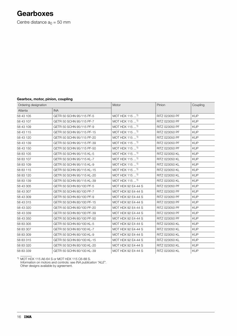
GearboxesCentre distance a0 = 50 mm
1) MOT HDX 115 A6-64 S or MOT HDX 115 C6-88 S.Information on motors and controls: see INA publication “ALE”.Other designs available by agreement.
Gearbox, motor, pinion, coupling
Ordering designation Motor Pinion Coupling
Atlanta INA
58 43 105 GETR 50 SCHN 95/115 PF-5 MOT HDX 115 ...1) RITZ 023050 PF KUP
58 43 107 GETR 50 SCHN 95/115 PF-7 MOT HDX 115 ...1) RITZ 023050 PF KUP
58 43 109 GETR 50 SCHN 95/115 PF-9 MOT HDX 115 ...1) RITZ 023050 PF KUP
58 43 115 GETR 50 SCHN 95/115 PF-15 MOT HDX 115 ...1) RITZ 023050 PF KUP
58 43 120 GETR 50 SCHN 95/115 PF-20 MOT HDX 115 ...1) RITZ 023050 PF KUP
58 43 139 GETR 50 SCHN 95/115 PF-39 MOT HDX 115 ...1) RITZ 023050 PF KUP
58 43 150 GETR 50 SCHN 95/115 PF-50 MOT HDX 115 ...1) RITZ 023050 PF KUP
58 83 105 GETR 50 SCHN 95/115 KL-5 MOT HDX 115 ...1) RITZ 023050 KL KUP
58 83 107 GETR 50 SCHN 95/115 KL-7 MOT HDX 115 ...1) RITZ 023050 KL KUP
58 83 109 GETR 50 SCHN 95/115 KL-9 MOT HDX 115 ...1) RITZ 023050 KL KUP
58 83 115 GETR 50 SCHN 95/115 KL-15 MOT HDX 115 ...1) RITZ 023050 KL KUP
58 83 120 GETR 50 SCHN 95/115 KL-20 MOT HDX 115 ...1) RITZ 023050 KL KUP
58 83 139 GETR 50 SCHN 95/115 KL-39 MOT HDX 115 ...1) RITZ 023050 KL KUP
58 43 305 GETR 50 SCHN 80/100 PF-5 MOT HDX 92 E4-44 S RITZ 023050 PF KUP
58 43 307 GETR 50 SCHN 80/100 PF-7 MOT HDX 92 E4-44 S RITZ 023050 PF KUP
58 43 309 GETR 50 SCHN 80/100 PF-9 MOT HDX 92 E4-44 S RITZ 023050 PF KUP
58 43 315 GETR 50 SCHN 80/100 PF-15 MOT HDX 92 E4-44 S RITZ 023050 PF KUP
58 43 320 GETR 50 SCHN 80/100 PF-20 MOT HDX 92 E4-44 S RITZ 023050 PF KUP
58 43 339 GETR 50 SCHN 80/100 PF-39 MOT HDX 92 E4-44 S RITZ 023050 PF KUP
58 43 350 GETR 50 SCHN 80/100 PF-50 MOT HDX 92 E4-44 S RITZ 023050 PF KUP
58 83 305 GETR 50 SCHN 80/100 KL-5 MOT HDX 92 E4-44 S RITZ 023050 KL KUP
58 83 307 GETR 50 SCHN 80/100 KL-7 MOT HDX 92 E4-44 S RITZ 023050 KL KUP
58 83 309 GETR 50 SCHN 80/100 KL-9 MOT HDX 92 E4-44 S RITZ 023050 KL KUP
58 83 315 GETR 50 SCHN 80/100 KL-15 MOT HDX 92 E4-44 S RITZ 023050 KL KUP
58 83 320 GETR 50 SCHN 80/100 KL-20 MOT HDX 92 E4-44 S RITZ 023050 KL KUP
58 83 339 GETR 50 SCHN 80/100 KL-39 MOT HDX 92 E4-44 S RITZ 023050 KL KUP
17
Gearboxes
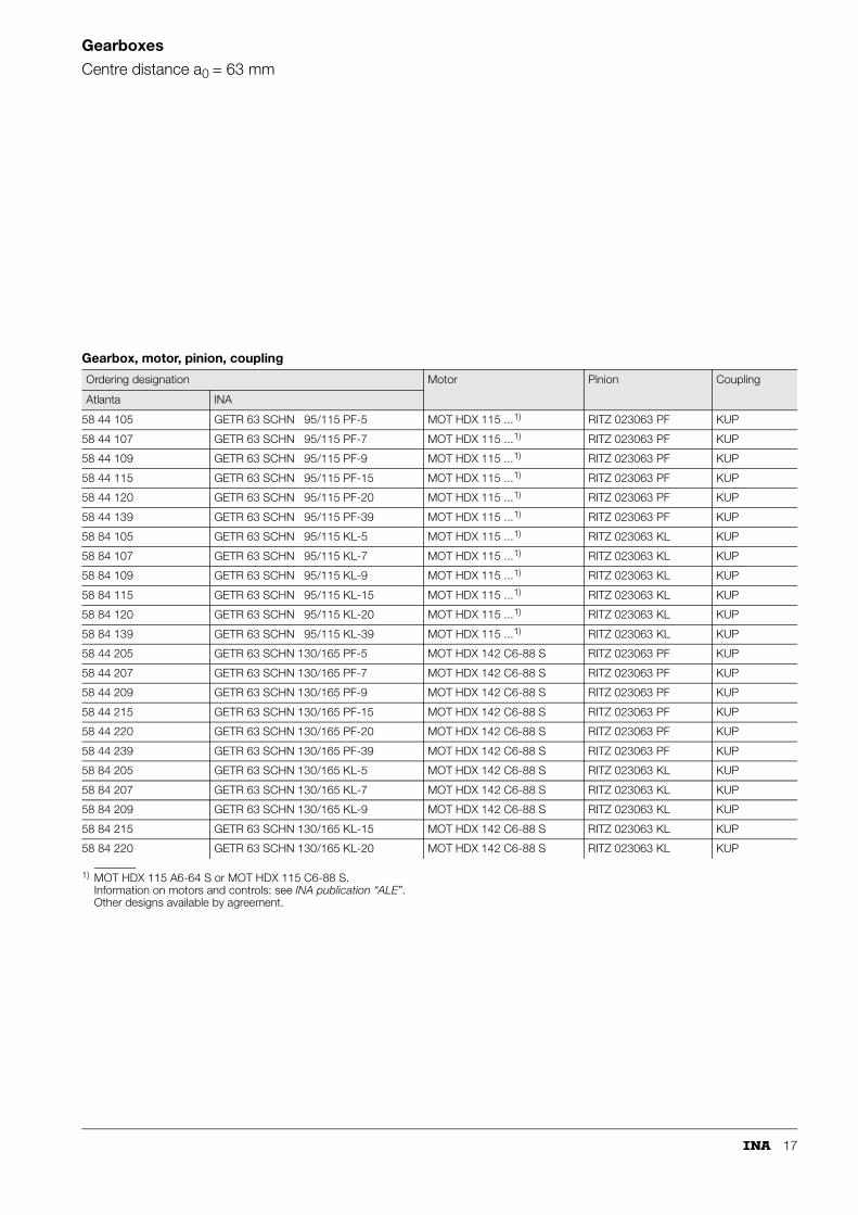
Centre distance a0 = 63 mm
1) MOT HDX 115 A6-64 S or MOT HDX 115 C6-88 S.Information on motors and controls: see INA publication “ALE”.Other designs available by agreement.
Gearbox, motor, pinion, coupling
Ordering designation Motor Pinion Coupling
Atlanta INA
58 44 105 GETR 63 SCHN 95/115 PF-5 MOT HDX 115 ...1) RITZ 023063 PF KUP
58 44 107 GETR 63 SCHN 95/115 PF-7 MOT HDX 115 ...1) RITZ 023063 PF KUP
58 44 109 GETR 63 SCHN 95/115 PF-9 MOT HDX 115 ...1) RITZ 023063 PF KUP
58 44 115 GETR 63 SCHN 95/115 PF-15 MOT HDX 115 ...1) RITZ 023063 PF KUP
58 44 120 GETR 63 SCHN 95/115 PF-20 MOT HDX 115 ...1) RITZ 023063 PF KUP
58 44 139 GETR 63 SCHN 95/115 PF-39 MOT HDX 115 ...1) RITZ 023063 PF KUP
58 84 105 GETR 63 SCHN 95/115 KL-5 MOT HDX 115 ...1) RITZ 023063 KL KUP
58 84 107 GETR 63 SCHN 95/115 KL-7 MOT HDX 115 ...1) RITZ 023063 KL KUP
58 84 109 GETR 63 SCHN 95/115 KL-9 MOT HDX 115 ...1) RITZ 023063 KL KUP
58 84 115 GETR 63 SCHN 95/115 KL-15 MOT HDX 115 ...1) RITZ 023063 KL KUP
58 84 120 GETR 63 SCHN 95/115 KL-20 MOT HDX 115 ...1) RITZ 023063 KL KUP
58 84 139 GETR 63 SCHN 95/115 KL-39 MOT HDX 115 ...1) RITZ 023063 KL KUP
58 44 205 GETR 63 SCHN 130/165 PF-5 MOT HDX 142 C6-88 S RITZ 023063 PF KUP
58 44 207 GETR 63 SCHN 130/165 PF-7 MOT HDX 142 C6-88 S RITZ 023063 PF KUP
58 44 209 GETR 63 SCHN 130/165 PF-9 MOT HDX 142 C6-88 S RITZ 023063 PF KUP
58 44 215 GETR 63 SCHN 130/165 PF-15 MOT HDX 142 C6-88 S RITZ 023063 PF KUP
58 44 220 GETR 63 SCHN 130/165 PF-20 MOT HDX 142 C6-88 S RITZ 023063 PF KUP
58 44 239 GETR 63 SCHN 130/165 PF-39 MOT HDX 142 C6-88 S RITZ 023063 PF KUP
58 84 205 GETR 63 SCHN 130/165 KL-5 MOT HDX 142 C6-88 S RITZ 023063 KL KUP
58 84 207 GETR 63 SCHN 130/165 KL-7 MOT HDX 142 C6-88 S RITZ 023063 KL KUP
58 84 209 GETR 63 SCHN 130/165 KL-9 MOT HDX 142 C6-88 S RITZ 023063 KL KUP
58 84 215 GETR 63 SCHN 130/165 KL-15 MOT HDX 142 C6-88 S RITZ 023063 KL KUP
58 84 220 GETR 63 SCHN 130/165 KL-20 MOT HDX 142 C6-88 S RITZ 023063 KL KUP
18
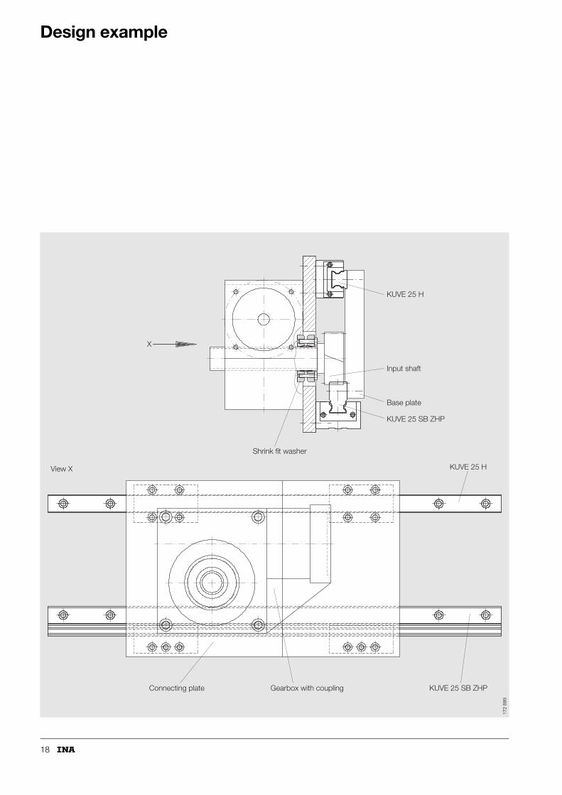
Design example
X
Input shaft
Shrink fit washer
Connecting plate Gearbox with coupling
View X
Base plate
KUVE 25 H
KUVE 25 H
KUVE 25 SB ZHP
KUVE 25 SB ZHP
172
889

19

INA-Schaeffler KGLinear Technology Division66406 Homburg (Saar) · GermanyInternet www.ina.comE-Mail [email protected] Germany:Telephone 0180 / 5 00 38 72Fax 0180 / 5 00 38 73From other countries:Telephone +49 / 68 41/ 7 01-0Fax +49 / 68 41/ 7 01-6 25 S
ach-
Nr.
004-
238-
036/
MA
I 54
GB
-D 0
2043
· P
rinte
d in
Ger
man
y


