Continuous Band Sealer Instruction Manual
Distributed By:
ABC Office
1142 West Flint Meadow DriveKaysville, UT 84037
www.abcoffice.comTel. (800) 658-8788Fax (801) [email protected]

1
Version 1.0_2014

ii
General Information
Thank you for purchasing our FR-770 band sealer.
This owner’s manual contains information relating to your band sealer machine. The manual will provideyou with basic information concerning both operation and maintenance of your new machine. Please read itcarefully as failure to do so may result in bodily injury and/or damage to the equipment.
Please fill in the information below. You will find the information on the machine identification plate. Youwill need this information when ordering replacement parts or making technical inquiries.
No part of this manual may be duplicated, reproduced, stored in a retrieval system, translated, transcribed, ortransmitted in any form without the express prior written permission of Sealer Sales.
F R - 7 7 0 E Q U I P M E N T I N F O R M A T I O N
Model #
Serial #
Purchase Date:
Reference # (found on packing slip)
Owner:

iii

Table of Contents
Safety Instructions ...........................................................................................1Introduction......................................................................................................3Operating your Band Sealer............................................................................7Maintenance....................................................................................................14Parts Diagram.................................................................................................16Troubleshooting.............................................................................................29Spare Parts List...............................................................................................31
F R - 7 7 0 I N S T R U C T I O N M A N U
Safety Instructions
WARNING! Below are general safety precautions and warnings that shouldprior to setting up or operating your equipment.using this unit. Your safety is most important! Failure to comply with procedures may result in serious injury orproperty damage. Remember: Your personal safety is your responsibility.
Unsafe practices or unauthorized modifications could result in accidents or property damage. Failure to fand take necessary precautions can result in serious injury as
Never operate or service your band sealer until you have read this manual completely and understand it fully.
Plug the band sealer into a standard 120 Volt, 60Hz wall outlet or surge protector.
Do not use the band sealer if the power cord, plug or any othercord to drape into your work area. Check thatCheck for all other conditions that may affect the oper
Reduce risk of unintentional starting. Make sure the power switch is in the "OFF" position before attaching to thepower source.
Always disconnect sealer from power source before servicing, changing accessories or cleaning the unit.
To provide protection against the risk of electrical shock
Do not leave the sealer unattended when in use. Disconnect the sealer from the power source before leaving the workarea.
Band sealer is used solely for sealing thermoplastic materials. Using the machine for any other purpose can causedamage to the machine and operator.thermoplastic materials.
Always operate machine on a flat stable
While operating machinery, wear closecaught in the machine. Do not wear jewelry
7 7 0 I N S T R U C T I O N M A N U A L
1
Safety Instructions
Below are general safety precautions and warnings that shouldprior to setting up or operating your equipment. Read and fully understand all instructions and warnings prior tousing this unit. Your safety is most important! Failure to comply with procedures may result in serious injury or
Your personal safety is your responsibility.
Unsafe practices or unauthorized modifications could result in accidents or property damage. Failure to fand take necessary precautions can result in serious injury as well as damage to equipment.
Never operate or service your band sealer until you have read this manual completely and understand it fully.
Plug the band sealer into a standard 120 Volt, 60Hz wall outlet or surge protector.
he power cord, plug or any other parts are damaged. Be surecord to drape into your work area. Check that all parts are operating properly and perform the intended functions.Check for all other conditions that may affect the operation.
Reduce risk of unintentional starting. Make sure the power switch is in the "OFF" position before attaching to the
Always disconnect sealer from power source before servicing, changing accessories or cleaning the unit.
tection against the risk of electrical shock, the power connection must be properly grounded at all times.
Do not leave the sealer unattended when in use. Disconnect the sealer from the power source before leaving the work
for sealing thermoplastic materials. Using the machine for any other purpose can causeoperator. Do NOT use the machine for any other purpose other than to seal
Always operate machine on a flat stable surface.
While operating machinery, wear close-fitting clothing and tie back long hair to prevent any external items from gettingcaught in the machine. Do not wear jewelry when operating the band sealer.
Below are general safety precautions and warnings that should be understoodRead and fully understand all instructions and warnings prior to
using this unit. Your safety is most important! Failure to comply with procedures may result in serious injury or
Unsafe practices or unauthorized modifications could result in accidents or property damage. Failure to follow these safety rules
Never operate or service your band sealer until you have read this manual completely and understand it fully.
parts are damaged. Be sure not to allow the powery and perform the intended functions.
Reduce risk of unintentional starting. Make sure the power switch is in the "OFF" position before attaching to the
Always disconnect sealer from power source before servicing, changing accessories or cleaning the unit.
the power connection must be properly grounded at all times.
Do not leave the sealer unattended when in use. Disconnect the sealer from the power source before leaving the work
for sealing thermoplastic materials. Using the machine for any other purpose can causeDo NOT use the machine for any other purpose other than to seal
to prevent any external items from getting

F R - 7 7 0 I N S T R U C T I O N M A N U A L
2
While machine is operating do not touch the heating and/or cooling blocks. Blocks will be extremely hot and mayburn your hands.
While machine is operating, do not place fingers, tools, or other foreign objects on or into the machine.Do not touch any moving parts while machine is operating. Fingers may get caught in between the gears and causesignificant injury.
Thermoplastic bags and material are hand fed into the machine. Place bag on the guide and carefully feed the bagthrough the band sealer. Fingers may be placed on the guide but do not allow fingers to touch any of the moving partson the band sealer.
Use emergency stop to turn off machine should material/bags get jammed into the machine. Carefully pull materialout of the band sealer. Do NOT use fingers to touch any part of the machine.
The band sealer is not water resistant or water proof. Spraying down the machine will damage machine or causeelectrical shock. Do not submerge the band sealer into water or liquid.
Do not operate band sealer in a corrosive or humid environment.
Always keep the machine clean, lubricated and in good working condition. Follow any maintenance and lubricationprocedures outlined in this manual. Make sure unit is disconnected from power source before cleaning
NEVER use any accessories or parts from other manufacturers. Machine should not be altered or modified usingparts that are not genuine authorized parts. Doing so will VOID YOUR WARRANTY.
Never leave the band sealer unattended. Be safe, disconnect the band sealer from power source before leaving workarea.
Close supervision is necessary when any appliance is near children or persons with reduced physical, sensory or mentalcapabilities or lack of experience and knowledge . This sealer is NOT to be used by children or by persons withreduced physical, sensory or mental capabilities or lack of experience and knowledge.
Do NOT use the band sealer outdoors.
Do NOT use the band sealer while under the influence of drugs, medications or alcohol.
SAVE THESE INSTRUCTIONS - REFER TO THEM OFTEN AND USE THEM TO INSTRUCT OTHERS.

F R - 7 7 0 I N S T R U C T I O N M A N U A L
3

F R - 7 7 0 I N S T R U C T I O N M A N U A L
4
Introduction
FR-770 is equipped with an electronic temperature controller and variable speed conveyor to seal all types ofthermoplastic materials (PP, PE, stand up pouches, gusseted bags, moisture barrier bags, etc.). Seals are created usingPTFE bands which maintain high seal quality and produce consistently strong, clean seals on all heat sealable bags.Because bags are placed on a conveyor system, the width of the bag does not matter. These versatile machines offerseveral adjustments which allow them to be used for a wide range of applications. These machines are usedextensively in the food/produce, medical, chemical, cosmetic, and electronic industries. The FR-770 band sealer willsignificantly increase efficiency of packaging your products.
There are two configurations for the FR-770 band sealer. The horizontal configuration (FR-770I) is primarily usedfor sealing dry materials and when you can lay flat your pouch. The vertical configuration (FR-770II) typically sealssmall solid products (ex: powders, grains, coffee) and liquids. In addition, sealing using the vertical configuration alsoworks best with stand up pouches.
Features of the FR-770 Band Sealer
Your band sealer is equipped with a wide range of standard features and capabilities.
Simple to use – minimal operator training
Rust inhibiting stainless steel construction
Equipped with bag entry guide for easy bag feeding and straight seals
Unit feeds left to right (see CBS-880 for right to left feeding)
Control panel includes industrial grade safety emergency stop switch
10amp protection power surge breaker
Includes pressure embossing coder
Wide seal (8mm) to assure airtight seal / Optional 15mm width sealer model available
PTFE sealing belts
Extended forced-air cooling system with extra wide cooling bars and 6 heat transfer orifices
One pair of brass sealing bars
Sealing method – constant heat
Adjustable 2-way pulley system for optimal stability and embossing clarity
Knurled pressure rolls with variable pressure adjustment
Fast warm up time
PID digital temperature controller 0-300˚C (572˚F) with dual alphanumeric displays (target & current temp)
Motorized rubber conveyor with speed control
Capable of speeds up to 472 inches/minute

F R - 7 7 0 I N S T R U C T I O N M A N U A L
How Does the FR-770 Work?
FR-770 is comprised oftemperature control systemwill cause a rapid
speed can be adjusted via the temperature controller and speed adjusting device. Plastic material to be sealed isplaced on the guide and conveyor. Conveyor willmaterial together. Material will then pass through the cooling blocks to allow the material to congeal.material will then pass through the embossing wheel for a meshed seal line.
The motor drives the sealing belts, drive belts and conveyor simultaneously.
Specifications
PowerMotor PowerSealing SpeedSealing WidthTemperature RangeConveyor SizeMax Conveyor LoadMin/Max Height of Bag (Vertical Only)
Character SizeEmbossing
DimensionsWeight
FR-770 Diagram
Figure 1. Horizontal Band Sealer (1) Guide, (2) Driven Wheel Seat (Adjusting Block)(8) Cooling Block, (9) Driving Wheel, (10) Embossing Roller, (11) Silicone Wheel, (12) Guiding Wheel, (13) Conveyor Belt, (14) Conveyor Table, (15) Fastening Knob for ElevatingTable, (16) Transverse Tightening Knob for Conveyor Table, (17)
Basic PrinciplesFR-770 is easy to use. Toseal, adjust temperature andplace bag on conveyor
A L
5
Work?
is comprised of a stainless steel frame, speed adjusting mechanism, sealingtemperature control system and transmission system. Turning on the heat for th
rise in the temperature of the heating blocks. Required temperaturtemperature controller and speed adjusting device. Plastic material to be sealed is
. Conveyor will then take the material between the two heating blocks to fuse theMaterial will then pass through the cooling blocks to allow the material to congeal.
material will then pass through the embossing wheel for a meshed seal line.
otor drives the sealing belts, drive belts and conveyor simultaneously.
FR-770I (Horizontal) FR110V/60Hz
50W0-472 inches/minutes
8mm (Optional 15mm width available)0-300˚C (572˚F)
38” x 7”6.6lbs
N/A3x4x9mm / 18PT
1 line embossing (2 lines available)3 sections w/ 15 characters/line
33” x 17” x 13”66lbs
(1) Guide, (2) Driven Wheel Seat (Adjusting Block), (3) Driven Wheel, (4) Control Panel, (5) Heating Block, (6) Holding Plate, (7) Pinch Roller,g Roller, (11) Silicone Wheel, (12) Guiding Wheel, (13) Conveyor Belt, (14) Conveyor Table, (15) Fastening Knob for Elevating
Table, (16) Transverse Tightening Knob for Conveyor Table, (17) Conveyor Support
stainless steel frame, speed adjusting mechanism, sealingand transmission system. Turning on the heat for the band sealer
rise in the temperature of the heating blocks. Required temperature andtemperature controller and speed adjusting device. Plastic material to be sealed is
material between the two heating blocks to fuse theMaterial will then pass through the cooling blocks to allow the material to congeal. Finally,
FR-770II (Vertical)
472 inches/minutes(Optional 15mm width available)
˚C (572˚F)
6” / 12”3x4x9mm / 18PT
mbossing (2 lines available)3 sections w/ 15 characters/line
33” x 17” x 22”87lbs
, (4) Control Panel, (5) Heating Block, (6) Holding Plate, (7) Pinch Roller,g Roller, (11) Silicone Wheel, (12) Guiding Wheel, (13) Conveyor Belt, (14) Conveyor Table, (15) Fastening Knob for Elevating
F R - 7 7 0 I N S T R U C T I O N M A N U A L
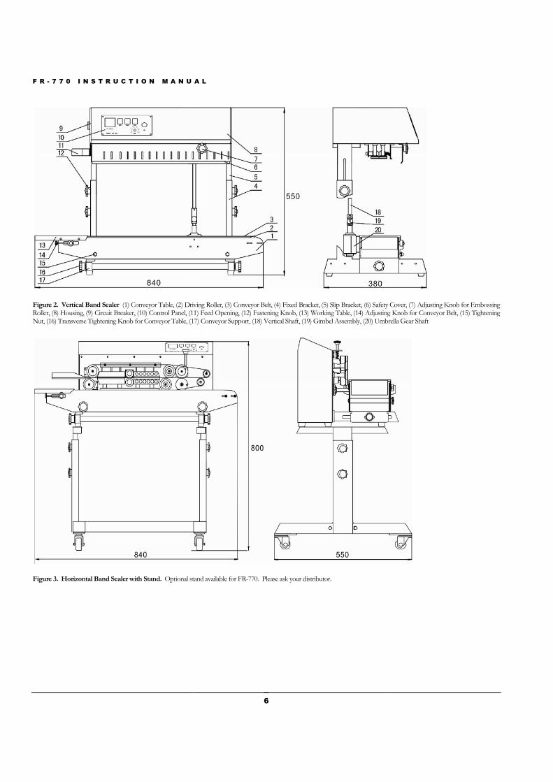
Figure 2. Vertical Band Sealer (1) Conveyor Table, (2) Driving Roller, (3) Conveyor Belt, (4) Fixed Bracket, (5) Slip Bracket, (6) Safety Cover, (7) AdjustiRoller, (8) Housing, (9) Circuit Breaker, (10) Control Panel, (11) Feed Opening, (12) FNut, (16) Transverse Tightening Knob for Conveyor Table, (17) Conveyor Support
Figure 3. Horizontal Band Sealer with Stand. Optional stand available for
A L
6
(1) Conveyor Table, (2) Driving Roller, (3) Conveyor Belt, (4) Fixed Bracket, (5) Slip Bracket, (6) Safety Cover, (7) AdjustiRoller, (8) Housing, (9) Circuit Breaker, (10) Control Panel, (11) Feed Opening, (12) Fastening Knob, (13) Working Table, (14) Adjusting Knob for Conveyor Belt, (15) Tightening
ob for Conveyor Table, (17) Conveyor Support, (18) Vertical Shaft, (19) Gimbel Assembly, (20) Umbrella Gear Shaft
Optional stand available for FR-770. Please ask your distributor.
(1) Conveyor Table, (2) Driving Roller, (3) Conveyor Belt, (4) Fixed Bracket, (5) Slip Bracket, (6) Safety Cover, (7) Adjusting Knob for Embossingable, (14) Adjusting Knob for Conveyor Belt, (15) Tightening
, (18) Vertical Shaft, (19) Gimbel Assembly, (20) Umbrella Gear Shaft
F R - 7 7 0 I N S T R U C T I O N M A N U A L
7
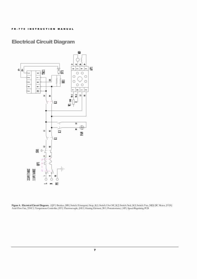
Electrical Circuit Diagram
Figure 4. Electrical Circuit Diagram. (QF1) Breaker, (SB1) Switch/Emergency Stop, (K1) Switch/On-Off, (K2) Switch/Seal, (K3) Switch/Fan, (MD) DC Motor, (FAN)Axial-Flow Fan, (THC1) Temperature Controller, (ST1) Thermocouple, (HE1) Heating Element, (W1) Potentiometer, (AP1) Speed-Regulating PCB
F R - 7 7 0 I N S T R U C T I O N M A N U A L
8
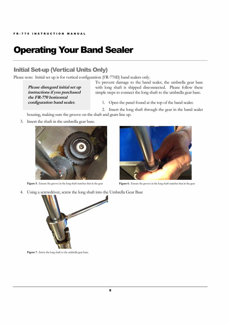
Operating Your Band Sealer
Initial Set-up (Vertical Units Only)Please note: Initial set up is for vertical configuration (FR-770II) band sealers only.
To prevent damage to the band sealer, the umbrella gear basewith long shaft is shipped disconnected. Please follow thesesimple steps to connect the long shaft to the umbrella gear base.
1. Open the panel found at the top of the band sealer.
2. Insert the long shaft through the gear in the band sealerhousing, making sure the groove on the shaft and gears line up.
3. Insert the shaft in the umbrella gear base.
Figure 5. Ensure the groove in the long shaft matches that in the gear Figure 6. Ensure the groove in the long shaft matches that in the gear
4. Using a screwdriver, screw the long shaft into the Umbrella Gear Base
Figure 7. Screw the long shaft to the umbrella gear base.
Please disregard initial set upinstructions if you purchasedthe FR-770 horizontalconfiguration band sealer.
F R - 7 7 0 I N S T R U C T I O N M A N U A L
Operation Set-up
1. Our machines are equipped with a threesocket to ensure safe operation.
2. Make sure the circuit breaker is in the “ON” posi
3. First time operation. Allow the machine to preThis would apply if the machine has not been in operation for a long time. The machine can sometimes bedamp from storage or shipment and running at a low temperature will d
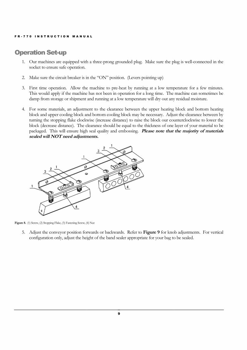
4. For some materials, an adjustment to the clearance between the upper heating block and bottom heatingblock and upper cooling block and bottom cooling block may be necessary. Adjust the clearance between byturning the stopping flake clockwise (increase distance) to raise the block our counterclockwise to lower theblock (decrease distance). The clearance should be equal to the thickness of one layer of your material to bepackaged. This will ensure high seal quality and embsealed will NOT need adjustments.
Figure 8. (1) Screw, (2) Stopping Flake, (3) Fastening Screw, (4) Nut
5. Adjust the conveyor position forwards or backwardsconfiguration only, adjust the height of the band sealer
A L
9
Our machines are equipped with a three-prong grounded plug. Make sure the plug is well
Make sure the circuit breaker is in the “ON” position. (Levers pointing up)
Allow the machine to pre-heat by running at a low temperature for a few minutes.This would apply if the machine has not been in operation for a long time. The machine can sometimes be
storage or shipment and running at a low temperature will dry out any residual moisture.
For some materials, an adjustment to the clearance between the upper heating block and bottom heatingblock and upper cooling block and bottom cooling block may be necessary. Adjust the clearance between by
ng flake clockwise (increase distance) to raise the block our counterclockwise to lower theblock (decrease distance). The clearance should be equal to the thickness of one layer of your material to bepackaged. This will ensure high seal quality and embossing. Please note that the majority of materialssealed will NOT need adjustments.
(1) Screw, (2) Stopping Flake, (3) Fastening Screw, (4) Nut
Adjust the conveyor position forwards or backwards. Refer to Figure 9 for knob adjustments. For verticalconfiguration only, adjust the height of the band sealer appropriate for your bag to be sealed.
prong grounded plug. Make sure the plug is well-connected in the
heat by running at a low temperature for a few minutes.This would apply if the machine has not been in operation for a long time. The machine can sometimes be
ry out any residual moisture.
For some materials, an adjustment to the clearance between the upper heating block and bottom heatingblock and upper cooling block and bottom cooling block may be necessary. Adjust the clearance between by
ng flake clockwise (increase distance) to raise the block our counterclockwise to lower theblock (decrease distance). The clearance should be equal to the thickness of one layer of your material to be
Please note that the majority of materials
for knob adjustments. For verticalappropriate for your bag to be sealed.

F R - 7 7 0 I N S T R U C T I O N M A N U A L
10
Figure 9. (1) Adjusting Knob, (2) Foot Rest
6. Adjust the guide to adjust seal width and position of seal line on your material.
F R - 7 7 0 I N S T R U C T I O N M A N U A L
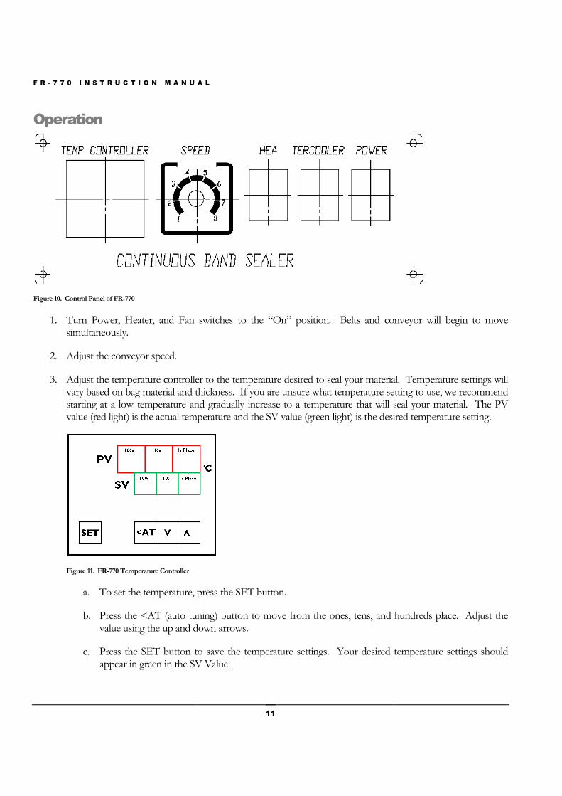
Operation
Figure 10. Control Panel of FR-770
1. Turn Power, Heater, and Fan switchessimultaneously.
2. Adjust the conveyor speed.
3. Adjust the temperature controller to the temperature desired to seal your material.vary based on bag material and thickness.starting at a low temperature and gradually increase to a temperature that will seal your material.value (red light) is the actual temperature and the SV value (green
Figure 11. FR-770 Temperature Controller
a. To set the temperature, p
b. Press the <AT (auto tuning) button tovalue using the up and down arrows.
c. Press the SET button to save the temperature settings.appear in green in the SV Value.
A L
11
Turn Power, Heater, and Fan switches to the “On” position. Belts and conveyor
Adjust the temperature controller to the temperature desired to seal your material.vary based on bag material and thickness. If you are unsure what temperature setting to usestarting at a low temperature and gradually increase to a temperature that will seal your material.
emperature and the SV value (green light) is the desired tem
temperature, press the SET button.
<AT (auto tuning) button to move from the ones, tens, and hundreds place. Adjust thedown arrows.
Press the SET button to save the temperature settings. Your desired temperature settings shouldappear in green in the SV Value.
conveyor will begin to move
Adjust the temperature controller to the temperature desired to seal your material. Temperature settings willwhat temperature setting to use, we recommend
starting at a low temperature and gradually increase to a temperature that will seal your material. The PVlight) is the desired temperature setting.
move from the ones, tens, and hundreds place. Adjust the
Your desired temperature settings should

F R - 7 7 0 I N S T R U C T I O N M A N U A L
d. Wait until the PV temperaminutes.
4. Adjust the pressure knob (Figurematerial.
5. Place material on the guide (FigureMake sure your material is flat on the guide. While the material is moving through thepush or pull the material as this will cause irregular sealing.
6. If the sealing belt is running off the guide wheelsdriven wheel seat (Figure 12, Item
Figure 12. (1) Driven Wheel Seat (Adjusting Block), (2) Driven Wheel Seat (Adjusting Block), (3)/(4) Adjusting Screws, (5) Springs
7. Emergency Stop – Press the emergency stop to turn off the machine. In order to restart the machine, youmust release the emergency stop by turning
8. To shut down, turn off the heater switch and allow the temperature of the machine to drop before toff the power and fan switches.of machine and sealing belts.
A L
12
Wait until the PV temperature matches the SV temperature which should
Figure 18 , Item #7) on your band sealer depending on
Figure 18 , Item #1) and allow the band sealer to pull your material through.Make sure your material is flat on the guide. While the material is moving through thepush or pull the material as this will cause irregular sealing.
running off the guide wheels, make adjustments to the screws that are found on thetem #1 & 2)
(1) Driven Wheel Seat (Adjusting Block), (2) Driven Wheel Seat (Adjusting Block), (3)/(4) Adjusting Screws, (5) Springs
the emergency stop to turn off the machine. In order to restart the machine, youmust release the emergency stop by turning the knob 120˚ clockwise.
turn off the heater switch and allow the temperature of the machine to drop before tFollowing the shut down procedure will significantly prolong the life
SV temperature which should take approximately 5-10
on your band sealer depending on the thickness of your bag
and allow the band sealer to pull your material through.Make sure your material is flat on the guide. While the material is moving through the band sealer, do not
, make adjustments to the screws that are found on the
the emergency stop to turn off the machine. In order to restart the machine, you
turn off the heater switch and allow the temperature of the machine to drop before turningFollowing the shut down procedure will significantly prolong the life
F R - 7 7 0 I N S T R U C T I O N M A N U A L
13
Installing the Embossing Wheel
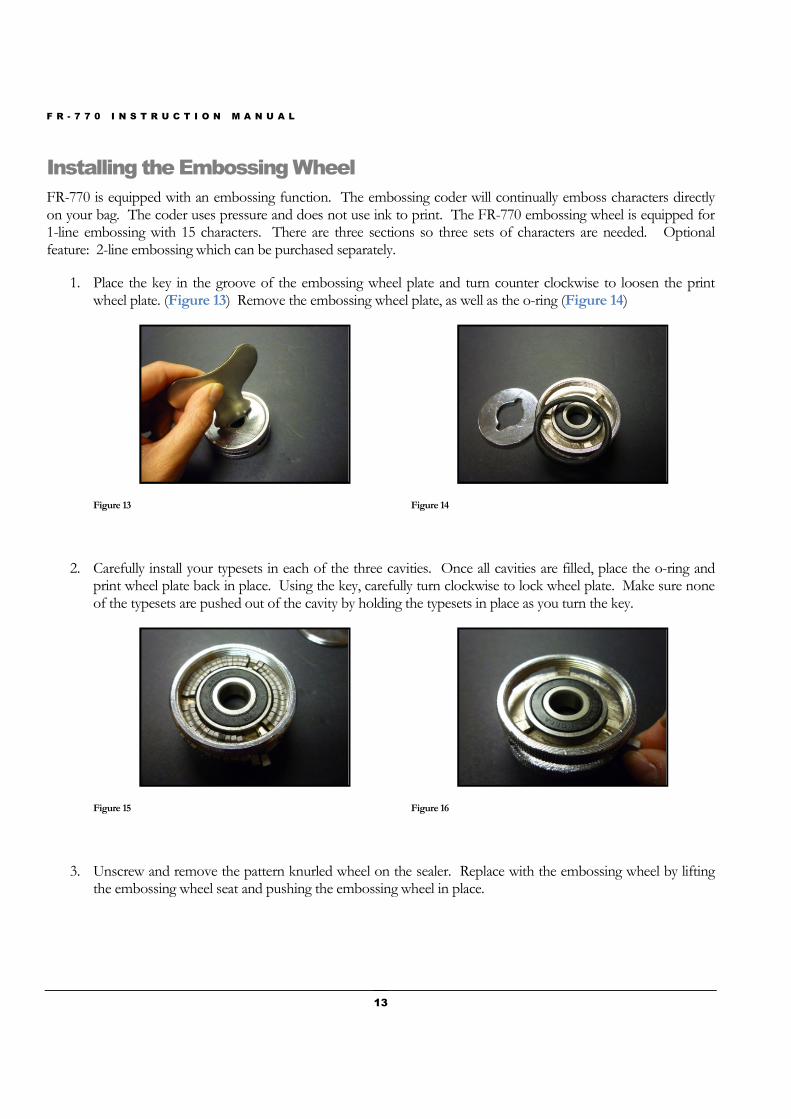
FR-770 is equipped with an embossing function. The embossing coder will continually emboss characters directlyon your bag. The coder uses pressure and does not use ink to print. The FR-770 embossing wheel is equipped for1-line embossing with 15 characters. There are three sections so three sets of characters are needed. Optionalfeature: 2-line embossing which can be purchased separately.
1. Place the key in the groove of the embossing wheel plate and turn counter clockwise to loosen the printwheel plate. (Figure 13) Remove the embossing wheel plate, as well as the o-ring (Figure 14)
Figure 13 Figure 14
2. Carefully install your typesets in each of the three cavities. Once all cavities are filled, place the o-ring andprint wheel plate back in place. Using the key, carefully turn clockwise to lock wheel plate. Make sure noneof the typesets are pushed out of the cavity by holding the typesets in place as you turn the key.
Figure 15 Figure 16
3. Unscrew and remove the pattern knurled wheel on the sealer. Replace with the embossing wheel by liftingthe embossing wheel seat and pushing the embossing wheel in place.

F R - 7 7 0 I N S T R U C T I O N M A N U A L
14
Sealing & Printing Optimization
1. Sealing performance can be adjusted with the sealing temperature and sealing speed. The higher the speedthe less exposure the material and therefore a higher temperature will be required to seal the material.
2. Try a variety of different sealing temperatures and conveyor speeds to get the optimal seal for your material.
3. Make adjustments to the pressing wheel with the pressure knob (Figure 18 , Item #7) to ensure a goodquality seal as well as a clear and visible embossed image.
F R - 7 7 0 I N S T R U C T I O N M A N U A L
15
Maintenance
The following maintenance procedures should be followed to ensure the longevity of your FR-770 band sealer.
Inspection and Cleaning
1. Inspect your machine daily.
2. Check if there is any foreign matter or dirt adhering to the band sealer.
3. To clean your band sealer, wipe down your sealer with silicone spray and a shop cloth. Do not apply siliconedirectly to your sealer. Definitely DO NOT wash down your machine with water.
Sealing and Drive Belts
1. Check and replace the belts as necessary. Both the sealing and drive belts are consumable items. Replacesealing belts when there are burn marks or if the belts become hard and brittle. Replace drive belts when thebelts break or become badly cracked.
2. To change out the belts, make sure the machine is turned off.
3. Remove the safety cover (Figure 18, Item #6).
4. Remove the two drive belts.
5. To remove the sealing belts, push on the adjustment blocks (Figure 18, Item #3) and the sealing beltsshould easily slip off.
6. Put new sealing and/or drive belts back on the machine. Test the machine, making adjustments asnecessary.
7. Replace the safety cover.
F R - 7 7 0 I N S T R U C T I O N M A N U A L
16
Turbocase Maintenance
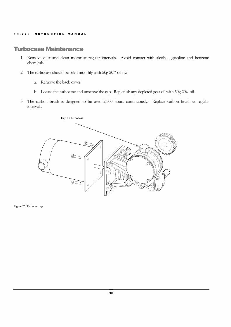
1. Remove dust and clean motor at regular intervals. Avoid contact with alcohol, gasoline and benzenechemicals.
2. The turbocase should be oiled monthly with 50g 20# oil by:
a. Remove the back cover.
b. Locate the turbocase and unscrew the cap. Replenish any depleted gear oil with 50g 20# oil.
3. The carbon brush is designed to be used 2,500 hours continuously. Replace carbon brush at regularintervals.
Figure 17. Turbocase cap.
Cap on turbocase

F R - 7 7 0 I N S T R U C T I O N M A N U A L
17
Parts Diagram
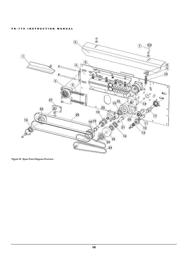
To order spare parts, please use diagram and part #s below:
Figure 18 – Spare Parts Diagram Overview
Figure 20 – Heating / Cooling Blocks
Figure 22 – Gears
Figure 24 – Conveyor Table
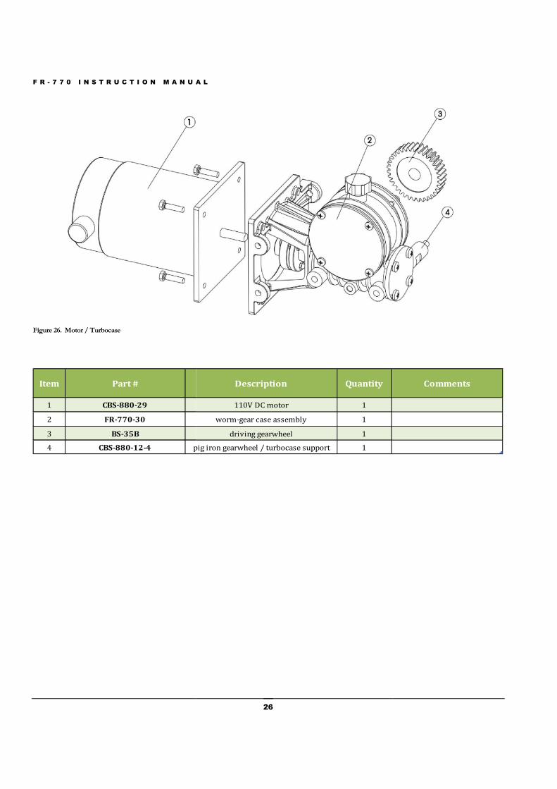
Figure 26 – Motor / Turbocase
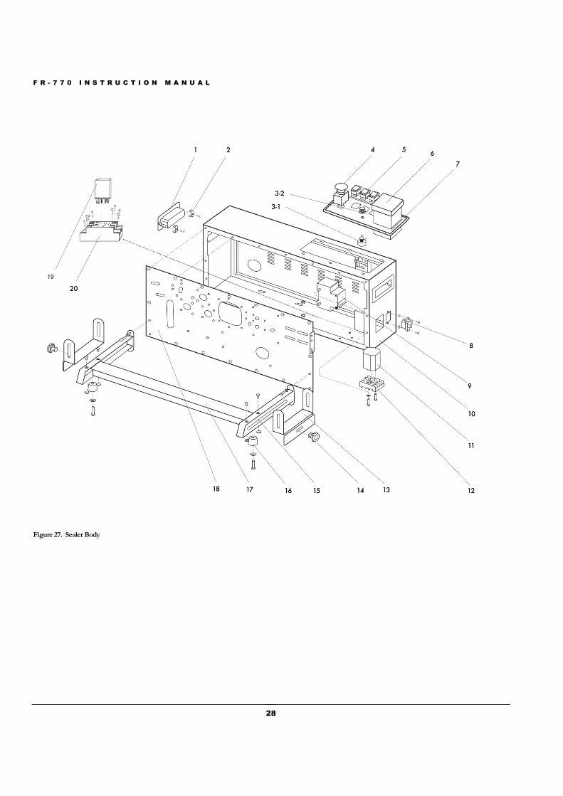
Figure 27 – Sealer Body
F R - 7 7 0 I N S T R U C T I O N M A N U A L
Figure 18. Spare Parts Diagram Overview
A L
18

F R - 7 7 0 I N S T R U C T I O N M A N U A L
19
Figure 19. Spare Parts Diagram Overview
Item Part # Quantity Description Comments
1 HL-M810-44 1 feed opening, guide
2 CBS-880-13A 2 spring for driven wheel seat
3 CBS-880-13 1 upper driven wheel seat, adjustment block assembly
4 FR-770-84 1 bottom board steel: 102102-3
5 CBS-880-8-5 1 support for safety cover
6 CBS-880-7 1 safety cover
7 BS-5 1 672 corrugated knob (M8X35)
8 BS-5B 1 supporting board for adjusting embossing roller
9 BS-5C 1 spring seat of embossing roller
10 BS-5A 1 spring of embossing roller
11 CBS-880-6B 2 small pulley shaft
12 CBS-880-6A 2 small pulley Includes #12, #13
13 CBS-880-6A 2 606-2Z bearing Includes #12, #13
14 CBS-880-4 1 embossing roller seat
15 CBS-880-3 1 embossing roller w/ cavities for types
15 CBS-880-3A 1 embossing roller, knurled wheel / meshed
16 CBS-880-6-26 9 6201-Z bearing
17 HL-M810-40A 1 drive shaft connector, gimbel assembly (outside)
HL-M810-40B 1 middle post connector to gimbel assembly (inside)
18 CBS-880-6 2 driving wheel
19 CBS-880-6-25 2 driving wheel shaft
20 CBS-880-27A 3 square bearing seat
21 CBS-880-2-31 1 silicone wheel shaft
22 CBS-880-2 1 silicone wheel
23 CBS-880-2-33 1 silicone wheel cover
24 CBS-880-26 2 guiding belt 428X6X4(40)
25 CBS-880-10 2 sealing belt 770X15X0.2
26 CBS-880-12 2 driven wheel
27 CBS-880-13 1 bottom driven wheel seat, adjustment block assembly

F R - 7 7 0 I N S T R U C T I O N M A N U A L
Figure 20. Heating / Cooling Blocks
A L
20

F R - 7 7 0 I N S T R U C T I O N M A N U A L
21
Figure 21. Heating / Cooling Blocks
Item Part # Quantity Description Comments
1 BS-9I 2 stopping flake
2 CBS-880-9-2 1 upper holding plate
3 BS-9J 2 hanger plate of copper block
4 CBS-880-21-19 1 lower pressing wheel shaft
5 BS-9F 4 self-made hexagon thin nut
6 BS-9D 4 spring for copper block
7 FR-770-9A 1 upper heating block (770) Includes #7, #9
8 BS-9B 2 300W/110V(Ф12X95) heating pipe for sealing sold as a pair
9 FR-770-9A 1 bottom heating block (770)
10 CBS-880-9-10 4 copper block cushion
11 CBS-880-9-11 1 bottom holding plate
12 CBS-880-21-23 1 slide seat for pressing wheel
13 CBS-880-21-24 1 upper pressing wheel shaft
14 FR-770-8 1 upper cooling block Includes #14, #17
15 CBS-880-21 2 61900-2Z bearing Includes #15, #16
16 CBS-880-21 2 pressing wheel / pinch roller Includes #15, #16
17 FR-770-8 1 bottom cooling block Includes #14, #17
CBS-880-21uppercomplete upper pressing wheel shaft assembly Includes #12-13, 15-16
CBS-880-21lowercomplete lower pressing wheel shaft assembly Includes #4, 15-16

F R - 7 7 0 I N S T R U C T I O N M A N U A L
Figure 22. Gears
A L
22

F R - 7 7 0 I N S T R U C T I O N M A N U A L
23
Figure 23. Gears
Item Part # Quantity Description Comments
1 HL-M810-40c bearing 6001 1 Includes #1, #2
2 HL-M810-40c connecting shaft bearing 1 Includes #1, #2
3 BS-35B driven gear 4
4 BS-35E medium gear 1
5 BS-35B driven gear 4
6 BS-35E-6 mediated gear shaft 1
7 BS-35B driven gear 4
8 HL-M810-32-horizontal fan - horizontal units 1
HL-M810-32-vertical fan - vertical units 1
9 BS-33B 10 pin wiring terminal(orange) 1

F R - 7 7 0 I N S T R U C T I O N M A N U A L
Figure 24. Conveyor Table
A L
24

F R - 7 7 0 I N S T R U C T I O N M A N U A L
25
Figure 25. Conveyor Table
Item Part # Description Quantity Comments
1 FR-770-1 conveyor belt 1
2 BS-16 adjusting block for conveyor belt 2 Includes #2, 3, 4
3 BS-16 double end bolt 2 Includes #2, 3, 4
4 BS-16 adjusting knob for conveyor table 2 Includes #2, 3, 4
5 HL-M810-36 6201-Z bearing 3 Includes #5, 6, 7, 8
6 HL-M810-36 bearing seat of left roller 2 Includes #5, 6, 7, 8
7 HL-M810-36 rear shaft of conveyor table 1 Includes #5, 6, 7, 8
8 HL-M810-36 rear roller of conveyor table 1 Includes #5, 6, 7, 8
9 HL-M810-18 half-round square neck bolt 2 Includes #9, 11, 12
10 HL-M810-15 worktable 1 specify flat or curved edges
11 HL-M810-18 plastic spacer 2 Includes #9, 11, 12
12 FR-770-18 / BS-17 knob 2 Includes #9, 11, 12
13 FR-770-20 conveyor table 1
14 HL-M810-41 bearing seat 1 Includes #5, 14-18
15 HL-M810-41 middle shaft of conveyor table 1 Includes #5, 14-18
16 HL-M810-41 sprocket of conveyor table 2 Includes #5, 14-18
17 HL-M810-41 connecting shaft bearing 1 Includes #5, 14-18
18 HL-M810-41 bearing 6001 1 Includes #5, 14-18
19 HL-M810-37 two-eye bearing seat 2 Includes #19, 20, 21, 22
20 HL-M810-37 front roller of conveyor table 2 Includes #19, 20, 21, 22
21 HL-M810-37 front shaft of conveyor table 1 Includes #19, 20, 21, 22
22 HL-M810-37 6201-2Z bearing 2 Includes #19, 20, 21, 22
23 FR-770-38 chain (48 segments) 1
F R - 7 7 0 I N S T R U C T I O N M A N U A L
Figure 26. Motor / Turbocase
Item Part #
1 CBS-880-29
2 FR-770-30
3 BS-35B
4 CBS-880-12-4 pig iron gearwheel / turbocase support
A L
26
Description Quantity
110V DC motor 1
worm-gear case assembly 1
driving gearwheel 1
pig iron gearwheel / turbocase support 1
Comments

F R - 7 7 0 I N S T R U C T I O N M A N U A L
27
F R - 7 7 0 I N S T R U C T I O N M A N U A L
28
Figure 27. Sealer Body
F R - 7 7 0 I N S T R U C T I O N M A N U A L
29
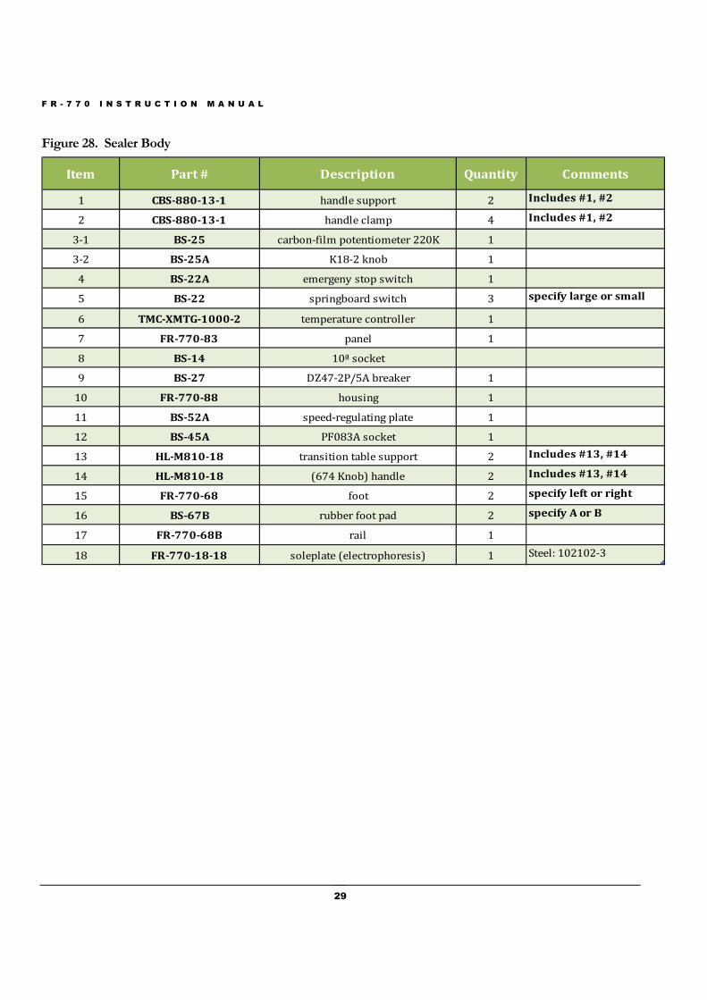
Figure 28. Sealer Body
Item Part # Description Quantity Comments
1 CBS-880-13-1 handle support 2 Includes #1, #2
2 CBS-880-13-1 handle clamp 4 Includes #1, #2
3-1 BS-25 carbon-film potentiometer 220K 1
3-2 BS-25A K18-2 knob 1
4 BS-22A emergeny stop switch 1
5 BS-22 springboard switch 3 specify large or small
6 TMC-XMTG-1000-2 temperature controller 1
7 FR-770-83 panel 1
8 BS-14 10ª socket
9 BS-27 DZ47-2P/5A breaker 1
10 FR-770-88 housing 1
11 BS-52A speed-regulating plate 1
12 BS-45A PF083A socket 1
13 HL-M810-18 transition table support 2 Includes #13, #14
14 HL-M810-18 (674 Knob) handle 2 Includes #13, #14
15 FR-770-68 foot 2 specify left or right
16 BS-67B rubber foot pad 2 specify A or B
17 FR-770-68B rail 1
18 FR-770-18-18 soleplate (electrophoresis) 1 Steel: 102102-3
F R - 7 7 0 I N S T R U C T I O N M A N U A L
30
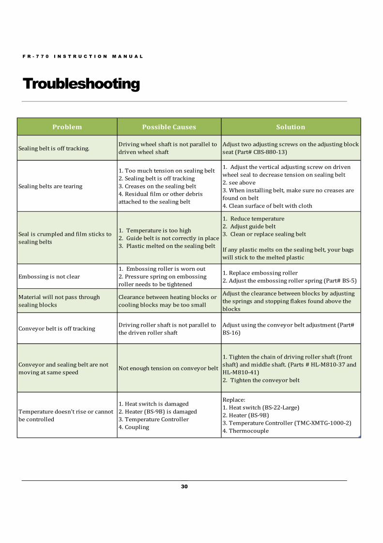
Troubleshooting
Problem Possible Causes Solution
Sealing belt is off tracking.Driving wheel shaft is not parallel to
driven wheel shaft
Adjust two adjusting screws on the adjusting block
seat (Part# CBS-880-13)
Sealing belts are tearing
1. Too much tension on sealing belt
2. Sealing belt is off tracking
3. Creases on the sealing belt
4. Residual film or other debris
attached to the sealing belt
1. Adjust the vertical adjusting screw on driven
wheel seal to decrease tension on sealing belt
2. see above
3. When installing belt, make sure no creases are
found on belt
4. Clean surface of belt with cloth
Seal is crumpled and film sticks to
sealing belts
1. Temperature is too high
2. Guide belt is not correctly in place
3. Plastic melted on the sealing belt
1. Reduce temperature
2. Adjust guide belt
3. Clean or replace sealing belt
If any plastic melts on the sealing belt, your bags
will stick to the melted plastic
Embossing is not clear
1. Embossing roller is worn out
2. Pressure spring on embossing
roller needs to be tightened
1. Replace embossing roller
2. Adjust the embossing roller spring (Part# BS-5)
Material will not pass through
sealing blocks
Clearance between heating blocks or
cooling blocks may be too small
Adjust the clearance between blocks by adjusting
the springs and stopping flakes found above the
blocks
Conveyor belt is off trackingDriving roller shaft is not parallel to
the driven roller shaft
Adjust using the conveyor belt adjustment (Part#
BS-16)
Conveyor and sealing belt are not
moving at same speedNot enough tension on conveyor belt
1. Tighten the chain of driving roller shaft (front
shaft) and middle shaft. (Parts # HL-M810-37 and
HL-M810-41)
2. Tighten the conveyor belt
Temperature doesn't rise or cannot
be controlled
1. Heat switch is damaged
2. Heater (BS-9B) is damaged
3. Temperature Controller
4. Coupling
Replace:
1. Heat switch (BS-22-Large)
2. Heater (BS-9B)
3. Temperature Controller (TMC-XMTG-1000-2)
4. Thermocouple
F R - 7 7 0 I N S T R U C T I O N M A N U A L
31
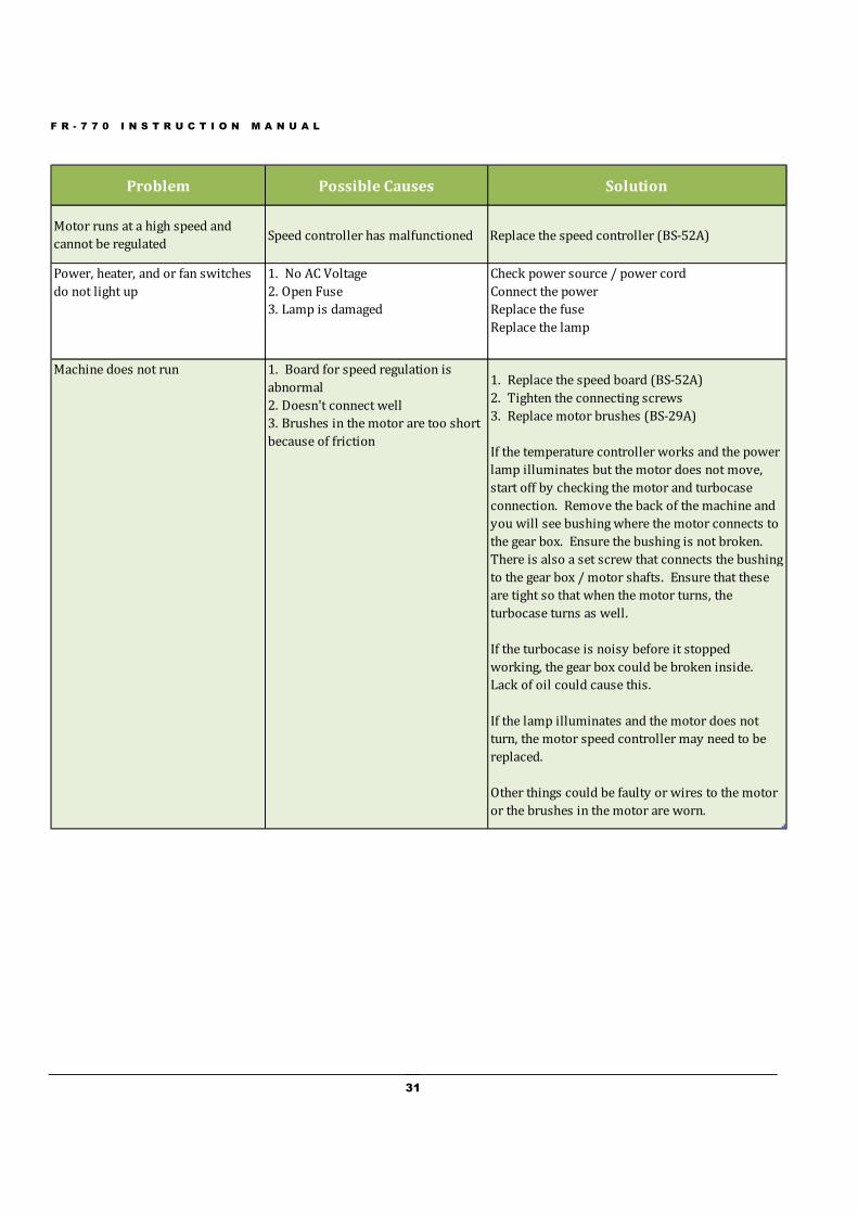
Problem Possible Causes Solution
Motor runs at a high speed and
cannot be regulatedSpeed controller has malfunctioned Replace the speed controller (BS-52A)
Power, heater, and or fan switches
do not light up
1. No AC Voltage
2. Open Fuse
3. Lamp is damaged
Check power source / power cord
Connect the power
Replace the fuse
Replace the lamp
Machine does not run 1. Board for speed regulation is
abnormal
2. Doesn't connect well
3. Brushes in the motor are too short
because of friction
1. Replace the speed board (BS-52A)
2. Tighten the connecting screws
3. Replace motor brushes (BS-29A)
If the temperature controller works and the power
lamp illuminates but the motor does not move,
start off by checking the motor and turbocase
connection. Remove the back of the machine and
you will see bushing where the motor connects to
the gear box. Ensure the bushing is not broken.
There is also a set screw that connects the bushing
to the gear box / motor shafts. Ensure that these
are tight so that when the motor turns, the
turbocase turns as well.
If the turbocase is noisy before it stopped
working, the gear box could be broken inside.
Lack of oil could cause this.
If the lamp illuminates and the motor does not
turn, the motor speed controller may need to be
replaced.
Other things could be faulty or wires to the motor
or the brushes in the motor are worn.
F R - 7 7 0 I N S T R U C T I O N M A N U A L
32
Spare Parts List
Included with your band sealer are the following parts. Please note that spare parts included with your band sealerare subject to change without notice.
Typeset Box which includes numbers (0-9), Letters - EXD, embossing wheel, and key wrench
Power Cord (Part# PWC-CBS)
PTFE Sealing Belts (Part# CBS-880-10)
Drive Belts (Part# CBS-880-26)
Speed Adjusting PC Board (Part# BS-52A)


